Green HVAC/R Technician Certification About Mainstream...
57
Green HVAC/R Technician Certification A Desktop Reference and Training Guide for Implementing Green Practices in Building Thermal Control and Commercial/Industrial Refrigeration Written by: Robert P. Scaringe, PhD, P.E Edited by: Charlotte Sykes First Edition April 2009 © Copyright 2009 ALL RIGHTS RESERVED Mainstream Engineering Corporation, Rockledge, Florida. Except as permitted by Sections 107 and 108 of the 1976 United States Copyright Act, no part of this publication may be reproduced or distributed in any form, or by any means, or stored in any database or retrieval system, without the prior written permission of the copyright owner. Information contained in this work has been obtained by Mainstream Engineering Corporation from sources believed to be reliable. However, neither Mainstream Engineering Corporation nor its author guarantees the accuracy or completeness of any information published herein, and neither Mainstream Engineering Corporation nor its author shall be responsible for any errors, omissions, or damages arising from the use of this information. This work is published with the understanding that Mainstream Engineering Corporation and its author are supplying information but are not attempting to render engineering or other professional or technical services. If such services are required, the assistance of an appropriate professional should be sought. About Mainstream Engineering Mainstream Engineering Corporation is a solutions-oriented research, development, and manufacturing small business founded in 1986. Mainstream‟s engineering mission is to research and develop emerging technologies and to engineer these technologies into superior-quality military and private-sector products that provide a technological advantage. Areas of expertise include thermal control, energy conversion, turbomachinery, chemical-based technologies, and nanotechnology. Over the years, Mainstream has published a widely read series of pragmatic certifications and manuals that focus on real-world knowledge and common- sense service techniques. You are among the thousands of technicians who have decided to take their professional development into their own hands by reading one of our manuals. After you have finished reading, we encourage you to continue your learning and development through applied experience, additional online education, and technician organizations such as the Refrigeration Service Engineers Society (RSES) (http://www.rses.org/main/index.cfm). We appreciate your comments and thank you for choosing Mainstream's online certification services. Send comments to info@mainstream- engr.com. Preface The information in this course is intended for educational purposes only. Procedures described are for use only by qualified air conditioning and refrigeration service technicians who are already well versed in HVAC/R service techniques and who hold valid EPA Section 608 Certification, Mainstream Indoor Air Quality (IAQ) Certification and Mainstream Preventative Maintenance Technician (PM Tech) certifications. This training course is not a substitute for the required EPA Section 608 certification or for any equipment Manufacturer’s Operator Manual. Take safety precautions when using all equipment. Improper use of any tool or piece of equipment can cause serious personal injury. Always use extreme caution when working with refrigerants. Always wear safety glasses. Never turn on any equipment if you do not understand its operation. Where procedures described in this manual differ from
Transcript of Green HVAC/R Technician Certification About Mainstream...

Green HVAC/R Technician Certification
A Desktop Reference and Training Guide for
Implementing Green Practices in Building Thermal Control and Commercial/Industrial Refrigeration
Written by: Robert P. Scaringe, PhD, P.E Edited by: Charlotte Sykes
First Edition
April 2009
© Copyright 2009
ALL RIGHTS RESERVED
Mainstream Engineering Corporation, Rockledge, Florida.
Except as permitted by Sections 107 and 108 of the 1976 United States Copyright Act, no part of this publication may be reproduced or distributed in any form, or by any means, or stored in any database or retrieval system, without the prior written permission of the copyright owner.
Information contained in this work has been obtained by Mainstream Engineering Corporation from sources believed to be reliable. However, neither Mainstream Engineering Corporation nor its author guarantees the accuracy or completeness of any information published herein, and neither Mainstream Engineering Corporation nor its author shall be responsible for any errors, omissions, or damages arising from the use of this information. This work is published with the understanding that Mainstream Engineering Corporation and its author are supplying information but are not attempting to render engineering or other professional or technical services. If such services are required, the assistance of an appropriate professional should be sought.
About Mainstream Engineering
Mainstream Engineering Corporation is a solutions-oriented research, development, and manufacturing small business founded in 1986. Mainstream‟s engineering mission is to research and develop emerging technologies and to engineer these technologies into superior-quality military and private-sector products that provide a technological advantage. Areas of expertise include thermal control, energy conversion, turbomachinery, chemical-based technologies, and nanotechnology.
Over the years, Mainstream has published a widely read series of pragmatic certifications and manuals that focus on real-world knowledge and common-sense service techniques. You are among the thousands of technicians who have decided to take their professional development into their own hands by reading one of our manuals. After you have finished reading, we encourage you to continue your learning and development through applied experience, additional online education, and technician organizations such as the Refrigeration Service Engineers Society (RSES) (http://www.rses.org/main/index.cfm).
We appreciate your comments and thank you for choosing Mainstream's online certification services. Send comments to [email protected].
Preface
The information in this course is intended for educational purposes only. Procedures described are for use only by qualified air conditioning and refrigeration service technicians who are already well versed in HVAC/R service techniques and who hold valid EPA Section 608 Certification, Mainstream Indoor Air Quality (IAQ) Certification and Mainstream Preventative Maintenance Technician (PM Tech) certifications.
This training course is not a substitute for the required EPA Section 608 certification or for any equipment Manufacturer’s Operator Manual. Take safety precautions when using all equipment. Improper use
of any tool or piece of equipment can cause serious personal injury. Always use extreme caution when working with refrigerants. Always wear safety glasses. Never turn on any equipment if you do not understand its operation. Where procedures described in this manual differ from

those of a specific equipment manufacturer, the equipment manufacturer’s instructions should be followed.
Mainstream Engineering Corporation assumes no liability for the use of information presented in this publication. This information is presented for educational purposes only. Manufacturer‟s Operator Manuals must be consulted for the proper operation of any piece of equipment.
The content of this course is limited to information and service practices needed to effectively reduce green house gas emissions, reduce the escape of ozone depleting substances, and extend the operating life of vapor-compression equipment, typically utilized in the HVAC/R industry.
This manual is not intended to teach fundamental air conditioning or refrigeration system techniques or safety practices. Likewise, this manual is not intended to teach safe refrigerant recovery or refrigerant handling techniques. This manual assumes the technician is well versed with these issues and possesses an EPA-Approved Section 608 certification.
Examination Information
The Green HVAC/R Technician certification exams consist of 25
questions. Technicians can take the Green HVAC/R Technician certification exam as many times as necessary (passing grade is 21 correct out of the 25 questions, or 84%). The exams are open-book and technicians have a maximum of 3 hours to complete the exam. If you retake the exam, you will automatically be given a different set of questions from the test bank.
Only EPA 608 CERTIFIED TECHNICIANS can obtain a Green HVAC/R certification. The Green Certification exam costs $24.95 which includes a
wallet-sized certification card. Opportunities to retake the test if you do not pass the first time cost $5.95. All are available online at www.epatest.com. The 25 questions that make up the exam cover Green HVAC/R Technician practices for installing, servicing, repairing, and maintaining air conditioning, refrigeration, and heat pump systems.
Mainstream reserves the right to revoke the Green HVAC/R Technician certification given to any individual, at any time, and without prior notice, for excessive customer complaints, unethical or illegal service practices, failure to meet Mainstream’s professional requirements, or
any other reason deemed justifiable by Mainstream employees. Mainstream is under no legal obligation to disclose the reason for the termination.
Table of Contents
About Mainstream Engineering Preface Examination Information Definitions Chapter 1 - Benefits of Green HVAC/R Technician Certification What is “Green HVAC/R”? Why Go “Green”? Green Certification and Green Buildings Green Building Certification Programs
Chapter 2 - Energy Audits and Energy-Saving Equipment and Systems Energy Audits Energy-Saving Equipment Set-Back Thermostats Air-to-Air Heat Exchangers Refrigerant–to-Water Heat Exchangers Economizers Solar Collectors Solar Domestic Potable Water Heaters Solar Pool Heaters Solar Films
Energy-Saving Systems Lighting Systems Motor Systems Cooling Systems Insulation Systems Steam Heating Systems Vapor Compression Systems
Chapter 3 - HVAC System Design Thermal Comfort Considerations Design Considerations Minimum Materials Specifications HVAC Design Methodology
Chapter 4 - HVAC System Installation General Guidelines Fabrication and Installation Guidelines
Chapter 5 - HVAC System Servicing Refrigerant Circuit Subsystem Air-Side Subsystem Electrical Subsystem Refrigerant Circuit Subsystem Maintenance Check Superheat and System Charge Check for Acid Check for Moisture Check for Corrosion
Chapter 6 - Indoor Air Quality Considerations Factors Affecting Indoor Air Quality Sources of Indoor Air Pollution Pollutant Pathways and Driving Forces HVAC System Natural Forces
Ventilation Considerations Duct Work Considerations Preventing Air Ducts from Getting Wet Treating Air Ducts Cleaning Air Ducts Unresolved Issues of Duct Cleaning

Mold Sampling and Control Symptoms and Complaints Typically Related to IAQ Problems Facility Operation and Maintenance Air Handler Air Filtration Mechanical Filtration Key Points about Air Cleaning
Chapter 7 - Refrigerant Handling Ozone Depletion Greenhouse Gases and Global Warming Refrigerant Conservation Methods to Minimize the Release of Refrigerants Keeping Systems Tight Evacuating Systems
Equipment Maintenance Brazing Techniques Brazing Safety
Chapter 8 - Hazardous Chemical Handling Chapter 9 - Financial and Environmental Incentives for Green Systems Economic Reasons Health Effects of Global Warming Health Effects of Ozone Depletion
Chapter 10 - Introduction to Green Marketing Examples of Green Marketing Advertising Green Services Additional Green Educational Websites and Sources
Definitions
Allergen Substance (such as dust mites, mold or
mold spores) that can cause an allergic reaction.
American Society of Heating Refrigeration and
Air Conditioning Engineers (ASHRAE)
An international organization, founded in 1894, to advance technology in heating,
ventilation, air conditioning and
refrigeration through research, standards writing, publishing, and continuing
education.
Annual Fuel Utilization Efficiency (AFUE) A rating of how efficiently a device
consumes fuel over an entire season of use. Minimum allowable AFUE rating
for various systems is:
Fossil fueled forced air
furnaces: 78%
Fossil fueled boilers: 80%
Fossil fueled steam boilers:
75%
APR A device designed to protect the wearer
(Air purifying respirator) from inhaling harmful dusts, fumes,
vapors, and/or gases. Forces contaminated air through a filtering
element.
ASTM (American Society for Testing and
Materials)
An international standards organization
for materials, products, systems, and services. Provides standards for various
aspects of the HVAC industry.
Biocide Substance or chemical that kills
organisms such as molds.
Building Information Modeling (BIM) A digital computer model of the physical
and functional characteristics of a facility. Includes Load Calculation and
Building Simulation Program. Model can
be created prior to construction to predict the effects of energy conservation
measures (ECM).
Building Occupants Describes people who spend extended
time periods in the building. Clients and
visitors are also occupants; they may have different tolerances and
expectations from those who spend their
entire workdays in the building, and they are likely to be more sensitive to odors.
Building Related Illness (BRI) Refers to illness brought on by exposure
to the building air, where symptoms of
diagnosable illnesses are identified (e.g., certain allergies or infections) and can be
directly attributed to environmental
agents in the air. Legionnaire’s disease and hypersensitivity pneumonitis are
examples of BRI that can have serious,
even life-threatening, consequences.
Building Simulation Program Part of BIM analysis. Uses information from Load Calculation Program, along
with Typical Meteorological Year (TMY)
weather data, and utility and equipment
data, to compute annual energy usage and
utility cost of operation.
Chimney Effect See Stack Effect
Coefficient of Performance (COP) A performance rating for any type of heat
pump or air conditioner. Defined as the
desired effect-namely, cooling or heating capacity-divided by the power consumed
to provide that effect, where the desired
effect and power consumed are in like

units. COPc, the Coefficient of
Performance in cooling, is the cooling capacity (in Btu/hr, for example) divided
by the electrical power consumed, in the
same units (Btu/hr in this example). Likewise, COPh, the
Coefficient of Performance in heating, is
the heating capacity divided by the electrical power consumed, expressed in
like units. Note that COP is similar to
Energy Efficiency Rating (EER), except that EER uses mixed units; that is, the
cooling or heating capacity is in Btu/hr
and the power consumed is in Watts. This is not a good idea, but it
represents a simplification of the COP
concept for non-technical individuals. See EER.
Note that COP typically decreases with temperature lift, and that an electric
(resistance) heater will have a (constant)
COPh of one, which means that one unit of electrical energy will produce one unit
of heat or work.
Also note that COPh is theoretically one
unit higher than COPc for the same lift; that is, COPh = COPc + 1 for the same
lift.
Cooling Load Calculation The amount of sensible heat and latent
heat gain added to the structure,
including the solar heat gain through the windows and infiltration through doors,
windows, and leaks. Used to determine
the size of the cooling system required.
Dew Point If the air is gradually cooled while maintaining the moisture content
constant, the relative humidity will rise
until it reaches 100%. This temperature, at which the moisture content in the air
will saturate the air, is called the dew
point. If the air is cooled further, some of the moisture will condense and form dew
or condensate liquid.
Dry-Bulb Temperature The temperature of the air measured with
a dry thermocouple or thermometer with
a dry bulb. The Dry-Bulb and Wet-Bulb
temperatures can be used together to determine relative humidity.
Energy Conservation An effort to reduce the amount of energy
needed to operate a device or process or
even eliminate it. Methods include building maintenance, equipment
replacement, addition of digital controls,
and energy recovery.
ECM
(Energy Conservation Measures)
Recommendations resulting from an
energy audit. Can include measures to
improve the efficiency of lighting,
HVAC equipment, utilities, and the
building itself.
Energy Efficiency Calculated by dividing the work produced by the energy used within a
process. The less energy consumed to
produce the work, the greater the energy efficiency.
Energy Efficiency Ratio (EER) Similar to COP, EER is a measure of the relative performance of a heating or
cooling appliance. Defined as the desired
effect-namely, cooling or heating capacity-in Btu/hr, divided by power
consumed, in Watts, to provide that
effect. Note that the desired effect and power consumed are in specific and
different units. EERc, the Energy Efficiency Ratio in cooling, is the cooling
capacity, in Btu/hr, divided by the
electrical power consumed, in Watts. Likewise, EERh, the Energy
Efficiency Ratio in heating, is the heating
capacity, in Btu/hr, divided by the electrical power consumed, in Watts.
While calculating a performance rating in mixed units is not proper engineering
methodology, this simplification of the
COP concept has been developed for non-technical individuals. The author
believes this is very bad idea; however, it
has become an industry standard, probably because it provides a larger
number. The EER will always be larger
than the COP for a system, because of the difference in units conversion, and can

give the appearance of better
performance. For example, an electric (resistance) heater will have a COPh of
1.0 and an EERh of 3.41.
To convert an EER to COP, simply
multiply the EER value by 0.293 to
obtain the equivalent COP value.
Energy Management A general term to cover the whole field of energy and its use. Can be divided into
energy consumption, demand, efficiency,
and conservation.
Enthalpy Total energy content
EPA (Environmental Protection Agency) Founded in 1970, the U.S. EPA leads the
nation's environmental science, research, education and assessment efforts. The
mission of the Environmental Protection
Agency is to protect human health and the environment. The HVAC/R industry
operates under EPA standards and
regulations.
Exfiltration A term used to describe uncontrolled air
moving out of a building.
First-hour rating Represents how much hot water a hot water heater can supply in a one-hour
period, when it starts with a full tank of
hot water. Found on energy guide label on the water heater.
Foot-Candle The quantity of light emitted by a candle
at a distance of one foot from the
candle. A light that produces 100 foot-candles of light means that, at one foot
from the light, you will receive the
equivalent of the light from 100 candles. The farther you move the light from what
you want to illuminate, the less light
intensity is available, because the light
has spread over a greater surface area.
The light intensity or brightness at the
source does not change, but the available or measured light decreases as the
distance increases.
Fungi Fungi are neither animals nor plants and
are classified in a kingdom of their own.
Fungi include molds, yeasts, mushrooms, and puffballs. In this document, the terms
fungi and mold are used interchangeably.
Molds reproduce by making spores. Mold spores waft through the indoor and
outdoor air continually. When mold
spores land on a damp spot indoors, they may begin growing and digesting
whatever they are growing on. Molds can
grow on virtually any organic substance, providing moisture and oxygen are
present. It is estimated that more than 1.5
million species of fungi exist.
Fungicide Substance or chemical that kills fungi
Ghost loads Also known as lazy loads, phantom
loads, or standby loads. Small drains of electricity that can add dollars to the
electric bill.
Halocarbon A halogenated hydrocarbon containing
one or more of the three halogens: fluorine, chlorine, and
bromine. Hydrogen may or may not be
present.
Heat exchanger A device that moves heat energy from
one fluid to another while maintaining a complete fluid separation.
Heating Season Performance Factor (HSPF) Like the EER, this is a mixed units
ratio. In this case, it is a ratio
of estimated seasonal heating output, divided by estimated seasonal power
consumption for an average U.S. climate.
Similar to SEER, which is for cooling, it estimates the heating season performance
by estimating the outdoor temperatures,
and it takes into account the efficiency of the equipment for an entire heating
season. The HSPF is more of a
marketing tool than a useful engineering metric. By using a seasonally averaged
outdoor temperature instead of the worst-
case temperature, a higher performance “number” is obtained, which looks good
on marketing literature.
Heat Load Calculation An evaluation of sensible heat loss from
a structure to the colder outside air as well as from infiltration through doors,
windows, and leaks. Used to determine
the size of the heating system required.

HEPA (High-Efficiency Particulate Air) A HEPA filter is one that can remove at
least 99.97% of airborne particles 0.3 micrometers (µm) in diameter.
Particles of this size are the most difficult
to filter and are thus considered the most penetrating particle size (MPPS).
Particles that are largeror smaller are
actually easier to filter out of the air.
Humidity The water vapor mixed with air in the atmosphere
Humidity Ratio Also known as Specific Humidity, it is
the ratio of the mass of water contained
in a mass of dry air. For example, the
pounds of water in a pound of dry air.
Hydrocarbon A compound containing only the elements hydrogen and carbon.
Hygroscopic Substances that readily absorb moisture. POE oils are hygroscopic.
Hypersensitivity Great or excessive sensitivity
IAQ (Indoor Air Quality)
Refers to the air quality within and around buildings and structures,
especially as it relates to the health and
comfort of building occupants. The
quality of breathable air within a
building.
Illuminating Engineering Society of North
America(IESNA)
A professional engineering society
related to lighting, which provides guidelines for amount and type of
lighting needed for particular task
areas. http://www.iesna.org/
Leak Rate The rate at which an appliance is losing refrigerant, measured between refrigerant
charges or over 12 months, whichever is
shorter. The leak rate is expressed in terms of the percentage of the appliance’s
full charge that would be lost over a 12-
month period if the current rate of loss were to continue over that period. The
rate is calculated by using the following
formula:
(Refrigerant added/Total Charge) x (365
days / year / D) x 100%
where D = the shorter of: # days since
refrigerant last added or 365 days
Life Cycle Cost Analysis A cost analysis that includes the total cost
of installing, operating, and maintaining a device for the total life of the device.
Low-Loss Fitting Any device that is intended to establish a connection between hoses, appliances, or
recovery/recycling machines, and that is
designed to close automatically or to be closed manually when disconnected to
minimize the release of refrigerant from
hoses, appliances, and recovery or
recycling machines.
Lumen One lumen is the quantity of light equal
to one foot-candle falling on one square
foot of area. A light that produces 10 lumens will have a light intensity of 10
foot-candles if it is illuminating one
square foot of area, or one foot-candle if it is illuminating 10 square feet. The
lumen is useful because it accounts for
the amount of light intensity on a surface.
Lumens per watt The ratio of the amount of lumens (light produced) divided by the energy
consumed (in Watts) to produce the light.
The larger this ratio, the more efficient the fixture.
Major Maintenance Maintenance, service, or repair that
involves removal of a vapor compression
system compressor, condenser, evaporator, or auxiliary heat exchanger
coil.
MERV (Minimum Efficiency Reporting Value)
Rating
A measurement designed by ASHRAE to
rate the effectiveness of air filters. Represents the worst-case performance of
a filter when dealing with particles in the
range of 0.3 to 10 microns. The MERV
rating is from 1 to 16. Higher MERV
ratings correspond to a greater percentage
of particles captured on each pass.
Mold Molds are a group of organisms that
belong to the kingdom Fungi. In this document, the terms fungi and mold are
used interchangeably. There are over
20,000 species of mold.
mVOC Microbial volatile organic compound, a

chemical made by a mold that may have
a moldy or musty odor
NFPA (National Fire Protection Association) International nonprofit established to reduce the worldwide burden of fire and
other hazards on the quality of life by
providing and advocating consensus codes and standards, research, training,
and education.
NIOSH (National Institute for Occupational Safety
and Health)
Federal agency responsible for
conducting research and making
recommendations for the prevention of
work-related injury and illness, disability,
and death by gathering information,
conducting scientific research, and translating the knowledge gained into
products and services.
OSHA (Occupational Safety and Health
Administration)
U.S. agency whose mission is to prevent
work-related injuries, illnesses, and deaths by issuing and enforcing rules
(called standards) for workplace safety
and health.
Package Terminal Air Conditioner (PTAC) An air conditioning system in which all
components are in a single cabinet (unitary).
PID Controller A proportional–integral–derivative
temperature controller (PID controller) is
a temperature controller that attempts to correct the error between the measured
temperature and the desired set point. It
corrects by using the integral, proportional, and derivative temperature
differences instead of simply the
temperature difference. This calculation more precisely predicts the thermal
response of the system and avoids
temperature undershoot or overshoot.
Reclamation To reprocess refrigerant to at least the
purity specified in the ARI Standard 700,
Specifications for Fluorocarbon
Refrigerants, and to verify this purity using the analytical test procedures
described in the Standard.
Recovery Efficiency The percentage of refrigerant in an
appliance that is recovered by a recycling
or recovery unit.
Recovery To remove refrigerant in any condition
from an appliance and to store it in an
external container without necessarily testing or processing it in any way.
Recycling To extract refrigerant from an appliance
and to clean refrigerant for reuse without
meeting all of the requirements for reclamation. In general, recycled
refrigerant is refrigerant that is cleaned
using oil separation and single or multiple passes through devices such as
replaceable-core filter driers, which
reduce moisture, acidity, and particulate
matter.
Refrigerant The fluid used for heat transfer in a refrigeration system which absorbs heat
during evaporation at low temperature
and pressure, and releases heat during condensation at a higher temperature and
pressure.
Relative Humidity The ratio of weight of water in the air
relative to the maximum weight of water that can be held in saturated air
Renewable Energy A repeatable source of energy, such as ethanol, a hydrocarbon fuel that can be
produced through distillation of plants.
Seasonal Energy Efficiency Ratio (SEER) Rating Like the EER, the SEER is a mixed units
ratio. In this case, it is a ratio of estimatedseasonal cooling output,
divided by estimated seasonal power
consumption for anaverage U.S. climate. Similar to HSPF, which is for heating, it
estimates the cooling season performance
by estimating the outdoor temperatures, and it takes into account the efficiency of
the equipment for an entire cooling
season. The SEER is more of a marketing tool than a useful engineering
metric. By using a seasonally averaged
outdoor temperature instead of the worst-case temperature, a higher performance
“number” is obtained, which looks good
on marketing literature. The minimum SEER rating for central air conditioning
systems is 13 as of Jan. 23, 2006.
Sensitization Repeated or single exposure to an
allergen that results in the exposed individual becoming hypersensitive to the

allergen.
SMACNA Sheet Metal and Air Conditioning
Contractors' National Association. Publishes standards and manuals that
address all facets of the sheet metal and
HVAC industry, from duct construction and installation to indoor air quality.
Solar insolation Solar radiation that has been received; the rate of delivery of direct solar radiation
per unit of horizontal surface.
Solar Rating and Certification Corporation
(SRCC)
An organization that provides
independent certification of solar water and swimming pool heating collectors
and systems. http://www.solar-rating.org/
Spore Molds reproduce by means of spores.
Spores are microscopic; they vary in
shape and size (2-100 micrometers). Spores may travel in several ways-they
may be passively moved (by a breeze or
water drop), mechanically disturbed (by a person or animal passing by), or actively
discharged by the mold (usually under
moist conditions or high humidity).
Stack Effect The pressure driven flow produced by
convection (the tendency of warm air to
rise) also called Chimney Effect.
Sustainable Energy Energy sources that will not be depleted
in a timeframe relevant to the human race. Examples are solar, wind,
geothermal, and hydro (including wave
and tidal power, as well as the more common hydro power plants that derive
power from water flowing over dams on
rivers).
Thermal mass A structure’s ability to store thermal
energy.
Thermosiphon system A plumbing arrangement that enables water in a heating apparatus to circulate
by means of convection. Hot water rising
and cold water descending in a plumbing loop to create water circulation.
UL (Underwriters Laboratories) A U.S. privately owned and operated independent, third-party product safety
testing and certification organization.
Develops standards and test procedures
for products, materials, components,
assemblies, tools and equipment, chiefly dealing with product safety. One of
several companies approved for such
testing by OSHA.
Vapor-Compression System The general term referring to all air conditioners, heat pumps, refrigerators
and chillers that all operate under the
principle of compressing a vapor to high pressure so that it will condense (at a
higher temperature), then dropping the
pressure to evaporate the refrigerant (to
provide cooling), followed by re-
compressing the refrigerant to condense
and complete the cycle.
Wet-Bulb Temperature The temperature of the air measured with
a wet thermocouple or thermometer with a wet bulb. The dry-bulb and wet-bulb
temperatures can be used together to
determine relative humidity.
Chapter 1 - Benefits of Green HVAC/R Technician Certification
As a certified Green HVAC/R Technician, you and your company can provide an extra level of service to your customers. By becoming green certified, you will be able to discuss incentives to “go green” with your customers and to provide these services.
The main incentive to installing green HVAC systems for most customers is cost savings. While green HVAC systems may have higher initial costs, they have lower life cycle costs because of greater efficiency and longer equipment life. Today‟s energy efficiency rating systems (EER) quantify these savings for your customers. In some cases, your customers may be able to take advantage of utility company and even tax rebates for installing green systems.
These systems also have unquantified benefits such as better human health from improved indoor air quality and better environmental health because of pollution control and lower fuel demands.
The Green HVAC/R Technician Certification program offered by Mainstream Engineering consists of training in techniques for maintaining or upgrading

existing HVAC systems to reduce pollution, improve efficiency, prolong equipment life, and improve indoor air quality. You will also learn how to design, install, and maintain a modern, high-efficiency HVAC system in accordance with the most current EPA standards.
After completing this course, you will be able to discuss with your customers incentives for improving the efficiency of existing systems or installing new, more efficient systems. You will be able to discuss with them information about reducing energy consumption and costs, improving indoor air quality (IAQ), and reducing emissions of harmful pollutants into the environment.
Certification consists of methods for:
Performing energy audits and selecting energy-saving equipment and systems. This is discussed in Chapter 2.
Designing, installing, and servicing HVAC to achieve maximum efficiency, thereby saving energy and reducing greenhouse gas emissions by power plants. Chapter 3 discusses methods for efficient design of HVAC systems. Chapter 4 discusses proper installation of HVAC systems, and Chapter 5 discusses servicing HVAC systems to maintain maximum efficiency and increase longevity.
Maintaining indoor air quality, to minimize energy consumption and avoid the use of harsh biocides to remedy problems that can otherwise be resolved with proper system design and maintenance. This is discussed in Chapter 6.
Minimizing the release of refrigerants during servicing and repair of HVAC/R systems. This is the subject of Chapter 7.
Avoiding the use of hazardous chemicals and preventing their escape into the environment; discussed in Chapter 8.
Educating the homeowner about the financial incentives for operating systems efficiently, including saving money while reducing greenhouse gas emissions. This is discussed in Chapter 9.
Marketing green services to your customers. This is discussed in Chapter 10.
What is “Green HVAC/R”?
In the context of the HVAC industry, “green” means systems that are healthful to building occupants, that are energy efficient, that reduce
environmental pollution and global warming, and that reduce long-term costs.
Home and business owners may feel that one person can make little difference by installing a green HVAC system. For example, someone might think it is okay to change the oil in their car and pour it down the storm drain, because it will not affect the vast amount of water in the world. The reality, however, is that over 30 times more motor oil is dumped by oil changes and road runoff annually than was spilled by the Exxon Valdez supertanker (source: Valerie Harms. The National Audubon Society Almanac of the Environment: The Ecology of Everyday Life, New York: G. P. Putnam‟s Sons, 1994, p. 93). Leading scientists, including about 2,500 scientists from the United Nations Intergovernmental Panel on Climate Change, agree that human activity causes pollution, vanquishes species, and is linked to global warming.
Why Go “Green”?
Green technologies must be money-saving technologies for them to become widespread. Green systems may cost more initially, but because they are more efficient and less expensive to operate, their life-cycle costs are lower. Cost recovery for these systems can be calculated by using energy rating systems such as the energy efficiency rating (EER). New, “green” products such as high-efficiency air conditioners, heat reclaiming hot water heat exchangers, light fixtures, and appliances must bear research and development costs and therefore do not currently have the economies of scale of their more predominant competitors. As a green certified technician, if you can demonstrate a financial and environmental justification, few consumers will not make the right, the green, choice. The goal of this program is to train the HVAC/R technician to support the building owner, with proven green money-saving techniques, thereby increasing Green Building implementations.
Green Certification and Green Buildings
The Green Technician certification program is not the same as a Green Building certification program, but the two go hand in hand. Green Building certification programs are typically designed to save energy, water, or both. Many building certification programs also address issues such as resource conservation, use of recycled products, durability, indoor air quality, and wildlife habitat. Mainstream‟s Green Certified HVAC/R Technician program is designed to educate the HVAC/R technician on methods to consider for reducing residential, commercial, and industrial energy use related to the

structure‟s heating and cooling, as well as commercial and industrial process cooling and refrigeration energy consumption.
The electrical power required for air conditioning and refrigeration often comes from the burning of fossil fuels at power plants, which contributes to smog, acid rain, and risks of global climate change. With green HVAC/R, less energy is used; therefore, less air pollution is generated and less money is spent on utility bills. It's a win-win situation.
Indoor environmental quality is also a significant issue to be addressed, because indoor air typically is more polluted than outdoor air. Excessive use of outdoor ventilation air to reduce indoor contaminants, without proper energy reclaim, can waste significant energy.
Building material selection, and even HVAC/R system selection, often is outside the control of the HVAC/R technician, as all of this may already be in place before a technician‟s first visit to the site. Mainstream‟s Green Certified HVAC/R technician training program focuses on existing structures and systems, and provides methods for reducing greenhouse gas emissions and global warming emissions by HVAC/R systems in residential, commercial, and industrial buildings.
Green Building Certification Programs
While Mainstream‟s Green HVAC/R technician certification program is a certification of the technician servicing the HVAC/R system and not the structure or contents, it is important to have a resource list of many of the common Green Building certifications. The Mainstream Green Certified technician may have the opportunity to point the building owner to such sites to aid in the overall improvement of the building. Many of these Building Certification Programs require hiring a trained (or approved or accredited) professional to rate or evaluate the building to determine whether it meets the standards of the certification agency or group. Many utility companies provide incentives to build green, and some counties and municipalities are requiring new construction to meet certain standards. Keep in mind that all of these programs change over time. Therefore, always check the associated Web sites for current program requirements.
LEED for Homes® is a nationwide program that certifies new
buildings that meet targets in an array of green building areas to make the building better for the occupant, environment, and community: http://www.usgbc.org
NAHB Green Building Program™ certifies builders who
incorporate various features of green construction in all of their projects: http://www.nahbgreen.org
ENERGY STAR® Qualified Homes are new homes built to meet
targeted energy reductions:http://www.energystar.gov
Chapter 2 - Energy Audits and Energy-Saving Equipment and Systems
This chapter gives a brief overview of energy audits and how they can be helpful in your efforts to implement green HVAC/R techniques. In addition, various types of energy-saving technologies that you can recommend to consumers are discussed. This chapter also covers energy savings that can be realized for lighting, electric motors, evaporative and passive cooling systems, heat pumps, insulation, steam heating systems, and vapor compression systems.
Energy Audits
An energy audit establishes where and how energy is being used in a structure. Energy audits should be done on residential, commercial, and industrial buildings. An energy audit identifies opportunities and provides recommendations for energy and cost savings. Recommendations can range from replacement or upgrading of heating, cooling, and refrigeration systems to improvements in maintenance of existing systems. Even teaching energy-saving behaviors to building occupants or installing setback thermostats can provide tremendous financial and energy savings. Any reduction in energy consumption translates into a reduction in green-house gas emissions and furthers the goal of minimizing global warming.
There are two types of audits:
A walk-through audit includes a visual inspection of a building‟s
energy systems and a review of energy usage data. This audit can identify simple operation and maintenance improvements and also helps determine if a more comprehensive audit is needed. This type of walkthrough should be part of every service call or pre-season tune-up.
A formal energy audit assesses all equipment and operational
systems and creates a more detailed calculation of energy use. This audit identifies potential technical improvements and makes

recommendations based on their projected energy and cost savings.
There are many common energy-saving features and systems that you can suggest to reduce energy consumption. Most local power companies provide free computer simulations to help you predict energy and cost savings. Contact your local power company or simply search the Internet for energy audit programs.
If you do perform a formal energy audit, be sure to obtain an accurate energy footprint for the building before any improvements are made. This baseline information is a necessary first step in identifying opportunities to reduce energy use and energy costs. Without this baseline data, you will not have the information necessary to make cost-effective decisions now and in the future about which energy-saving strategies to implement. Conducting an initial energy audit provides important data about a structure‟s carbon footprint and establishes a baseline upon which progress toward greenhouse gas reduction targets can be evaluated.
Benefits of energy audits include:
Reduced greenhouse gas emissions and air pollution.
Significantly lower electrical, natural gas, steam, water, and sewer costs.
Improved indoor air quality, lighting quality, and building occupant satisfaction.
While an in-depth discussion of energy audits is beyond the scope of this program, the basic information is provided so that the HVAC/R technician can create a custom audit for his or her applications. Every energy demand is unique, as is every energy-efficiency improvement opportunity. However, there are always energy recovery and energy saving systems that can decrease energy consumption, reduce operating costs, maximize return on investment, and reduce greenhouse gas emissions.
Energy-Saving Equipment
Common energy recovery and heat transfer products include:
Set-back thermostats
Air-to-air heat exchangers
Refrigerant-to-water heat exchangers
Economizers
Solar collectors
Solar films
Set-Back Thermostats
Set-back thermostats, also referred to as programmable thermostats, are one of the easiest ways you can save energy and money and help fight global warming, if they are actually programmed to perform the set-back function. Many individuals find them too difficult to program, and as a result they only function as an ordinary single-set-point thermostat. To avoid this problem, many new programmable thermostats make it easier to program by offering four pre-programmed settings to regulate a structure‟s temperature in both summer and winter. If you install or maintain a structure with a programmable thermostat, verify that it is programmed, and train the occupants in proper programming.
The government reports that the average household spends more than $2,000 a year on energy bills, nearly half of which goes to heating and cooling. The energy bill for cooling is of course much greater in the southern states. In any case, the average homeowner can save about $180 a year by properly setting their programmable thermostats and maintaining those settings. The pre-programmed settings that come with many programmable thermostats are intended to deliver savings without sacrificing comfort.
Always choose the right programmable thermostat for the occupants. Typically, there are three types of programmable thermostats designed to best fit the daily schedule of the occupants. To decide which model is best for your occupants, determine their schedule and how often they are away from home for regular periods of time-work, school, other activities-and then decide which of the three different models best fits their schedule: the 7-day, 5+2-day, or the 5-1-1-day. The 7-day models are best if the daily schedule tends to change every day of the week. They give you the most flexibility, and let you set different programs for different days, usually with four possible temperature periods per day. They are typically the most difficult to set, however, since the most options also mean the most features to set. Alternatively, 5+2-day models use the same schedule every weekday, and another for weekends. Finally, 5-1-1 models are best for those who tend to keep one schedule Monday through Friday and another schedule on Saturdays and Sundays. In general, most programmable thermostats are equipped with four pre-programmed settings and maintain those settings within two degrees.

The thermostat should be installed on an interior wall, away from heating or cooling vents and other sources of heat or drafts (doorways, windows, skylights, direct sunlight or bright lamps). Supply low-voltage power to programmable thermostats, rather than using the internal batteries. On many systems, when the batteries die, the thermostat stops operating, and if this should occur on a cold day, pipes can freeze and burst. If the thermostat batteries should fail at an unoccupied home during the humid summer months, the home could develop a serious mold problem before the problem is detected. This happens more times than you can imagine and causes thousands of dollars of damage. Always upgrade an old, manual thermostat to a programmable unit if you're replacing the heating or cooling system. If you're replacing a manual thermostat that has a mercury switch, be careful not to break the tube that holds this toxic mercury substance, and always follow proper recycling guidelines. Contact your local recycling/hazardous materials center or the manufacturer of your new thermostat for advice on proper disposal. A final thought on setting the thermostat: keep the temperature set at its energy savings set-points for long periods of time (at least 8 hours); for example, during the day, when no one is at home, and throughout the night, after bedtime.
Air-to-Air Heat Exchangers
The most common use for an air-to-air heat exchanger is to exchange heat between outdoor air being brought into a building and indoor, conditioned air being rejected from the building. This type of heat exchanger is commonly referred to as a heat recovery ventilator (HRV). In summer, the warm air from outside being brought into the structure is cooled by the conditioned air being rejected to the outside. In winter, the cold air from outside being brought into the structure is heated by the conditioned air being rejected to the outside.
HRVs can recapture 60% to 80% of the heating or cooling that would otherwise be lost. Units that exchange moisture between the two air streams are referred to as Energy Recovery Ventilators (ERVs). Such devices are more that simply a heat exchanger. They also have a desiccant wheel to absorb moisture from one stream and reject this moisture into the other stream. ERVs are used in climates where cooling loads place strong demands on HVAC systems; however, ERVs are not dehumidifiers. They transfer moisture from the humid air stream (incoming outdoor air in the summer) to the exhaust air stream. Unfortunately, many times these devices do not operate as well as advertised. The desiccant wheels quickly become saturated before they can reject the moisture to the exhaust stream, and the moisture transfer mechanism becomes less effective with successive use.
Although some window or wall mounted units are available, HRVs and ERVs are most often designed as ducted, whole-house systems. The heat exchanger is the heart of an HRV, usually consisting of a cube-shaped transfer unit made from special conductive materials. Incoming and outgoing airflows pass through different sides of the cube (but are not mixed), allowing conditioned exhaust air to raise or lower the temperature of incoming fresh air.
After passing through the heat exchanger, the warmed or cooled fresh air goes through the HVAC air handler, or may be sent directly to various rooms. Stale air from return ducts pre-conditions the incoming flow before exiting. Systems in various sizes and configurations are available to automatically maintain 0.35 air changes per hour, the rate usually recommended to maintain good air quality. Many systems include filters to further control contaminants that would otherwise recirculate through the home.
Conventional fan and vent assemblies for bathrooms and kitchens, often required by code, may allow significant energy losses. An HRV system can incorporate small, separately switched booster fans in these rooms to control moisture or heat generated by activities like showering or cooking. Odors and pollutants can quickly be removed, but energy used to condition the air is recycled in the heat exchanger. Some codes or applications may still require stoves to be separately vented for removal of grease or gas fumes.
Refrigerant–to-Water Heat Exchangers
Refrigerant-to-water heat exchangers are used to produce domestic hot water (or to heat pool water) from the waste heat normally rejected by the condensation of refrigerant in the system air conditioner. When the heat pump is operating in heat pump mode (heating mode – reverse cycle), the heat of condensation is not waste heat, but the domestic hot water is heated more efficiently than straight electric hot water heating. These hot water heating coils (heat exchangers) should be located upstream of the condenser; that is, between the compressor discharge and the condenser inlet. This heat exchanger not only provides free hot water when the air conditioner is operating, it also increases the air conditioner system performance. For a building with a three-ton air conditioner, one could expect from 15 to 25 gallons of hot water raised from 70 to 140 °F every hour the air conditioner is running. Similarly, for a five ton air conditioner, 25 to 40 gallons could be recovered.

This hot water would be available during the summer months when the air conditioner is running fairly consistently. As the outdoor temperatures decrease, the air conditioner will run less, thereby making less hot water available. With a heat pump, hot water from the heat recovery system is available during the winter as well as the summer months.
Even greater savings can be realized in some types of commercial establishments where the hot water requirements are heavy and there is a high internal heat gain from lights and people in the public area. This heat gain can cause the air conditioner to run even during the winter months. Some restaurants, motels, and laundromats have been able to obtain 100% of their hot water during the cooling season from the heat recovery system. Additional savings are realized from the reduced costs of operating the air conditioning system because of the supplemental condensing action of the refrigerant-to-water heat exchanger.
Economizers
The function of an economizer is, as its name implies, to “economize” or save on air conditioning costs. Obviously, it costs money to operate the compressor. If the compressor can be shut down and the system still provide adequate cooling, energy savings can be realized.
Heating and Cooling Economizers
Heat internal to a building, such as people, lights, computers, copy machines, motors and other machines, can at times cause the temperature inside a structure to increase above the outdoor temperature. Heat absorbed into the building structure may also continue to heat the building long after the temperature outside the building has dropped. There are times when the temperature outside a building is lower than the temperature inside, and outside air can be used to cool the interior instead of operating an air conditioning unit.
An economizer can save energy whenever the cooling system is calling for cooling and the temperature outside is cool enough that it is economical to shut off the compressor. In this situation, the economizer brings in cool outside air to satisfy the cooling needs of the building. This is the basic function of an air economizer system.
Since air economizers control and vary the amount of outside (fresh) air brought into a structure, they play an integral role in maintaining the quality
of indoor air. A properly operating economizer can greatly improve indoor air quality (IAQ) and reduce air-quality-related illnesses. Therefore, it is important for the service technician to have at least some knowledge of indoor air quality and its relationship to heating and cooling system operation.
Air economizers are available for residential and commercial systems and can be retrofitted to most systems as energy-conserving devices. Most packaged light commercial systems (rooftop systems) have an economizer add-on package as an option, which can be installed when the system is new or added to the system later.
Enthalpy-Controlled Economizers
There is a drawback, however, to relying on outside temperature to determine whether outside air instead of an active air conditioning system should be used to cool. While the outside air temperature may be below the indoor air temperature, the outside air may be too humid to provide adequate comfort for the building occupants. The occupants will feel cool but clammy.
The solution is an economizer control that checks to see whether the outside humidity is below the inside humidity. This type of control is called an “enthalpy” control. The term “enthalpy” means “total energy content”. For example, if the outside energy content (comprised of temperature and humidity) is lower-that is, cooler-then it is advantageous to use outside air to cool the structure. An enthalpy control measures both sensible (temperature) and latent (humidity) heat in the air and only allows outside air to be used for cooling if the air is both cool and dry enough to satisfy the space conditions. This combination provides for the greatest comfort at the lowest operating cost, thereby saving the most energy.
If the indoor thermostat calls for cooling, and the outside air enthalpy (total heat) is low enough, then the economizer brings in this cooler and less humid air and uses it for cooling instead of operating the compressor. Using the outside air for cooling is less expensive than operating the compressor to provide cooling.
Not all economizers use enthalpy controls. Some just check the outside air temperature and do not check the outside air humidity. Those controls do not provide the same levels of comfort as enthalpy-controlled economizers.

Economizer Maintenance
Economizers can save a great deal of energy. They can also waste energy if they are not operating properly or are improperly adjusted. The cost of a service call to repair such a problem is often less than the cost of one or two months of wasted energy. For example, if the outside air dampers are not closing properly when the outside air temperature is high, then hot air is unnecessarily entering the building. When this occurs, the air conditioning compressor operates longer and under higher loads and thus consumes a great deal more energy than necessary.
Many economizers are not functioning at all or are out of service because they are not well understood by some service technicians. Some service technicians simply disable them. It is essential that economizers are working properly and saving energy rather than increasing costs.
The following items should be checked at least annually to ensure the air economizer is operating properly:
Setting and operation of the outdoor thermostat or enthalpy control.
Condition of the outdoor thermostat or enthalpy control.
Proper setting and operation of the economizer mixed air thermostat.
Proper damper operation and lubrication.
Minimum damper position adjustment.
Correct operation of the system when a call for cooling comes from the thermostat.
Function and condition of the economizer damper motor.
Condition of the wiring and electrical terminations.
Because the enthalpy control is located in the outdoor air airstream and is a relatively sensitive control, it is not uncommon to have to replace it every few years, depending upon the location of the equipment and the weather extremes in the area. The cost of a replacement control is usually recovered quickly through the energy saved. Economizer service should be part of the scheduled maintenance performed at least on a yearly basis.
Solar Collectors
You have probably been hearing about the "solar revolution" for the last 20 years- the idea that one day we will all use free electricity from the sun. This
is a seductive promise. On a bright, sunny day, sunshine creates approximately 1,000 watts of energy per square meter of the planet's surface. If we could collect all of that energy, we could easily power our homes and offices for free. Of course, we cannot collect all of the energy that falls on the earth, and the collection efficiency is not 100%. However, there are devices that can collect and use some of the sun‟s energy in the form of electricity or heat. These devices are called solar collectors. There
are essentially two types of solar collectors: solar collectors that produce electricity, and solar collectors that produce heat in the form of a hot liquid or hot air. Solar collectors that produce electricity are called electric solar cells, and those that produce heat are called thermal solar collectors.
Electric Solar Cells
The solar cells that you see on calculators and satellites are a type of electric solar cell known as a photovoltaic (PV) cell.PV cells, as the word implies (photo=light, voltaic=electricity), convert sunlight directly into electricity. Once used almost exclusively in space, PV cells are now used in many more common ways. PV cells can be grouped into PV modules, which are PV cells electrically connected and packaged in one frame.
PV cells are made of special materials called semiconductors. Silicon is the most commonly used semiconductor material. When light strikes a PV cell, a certain portion of it is absorbed within the semiconductor material, and the energy of the absorbed light is transferred to the semiconductor. The energy knocks electrons loose, allowing them to flow freely.
PV cells also have one or more electric fields that force electrons freed by light absorption to flow in a certain direction. This flow of electrons is a current, and by placing metal contacts on the top and bottom of the PV cell, the current can be drawn off and used externally. For example, the current can be used to power a calculator. This current, together with the cell's voltage (which is a result of its built-in electric fields), defines the power (or wattage) that the solar cell can produce.
PV cells in modules mounted on, for example, a building‟s roof, convert sunlight into direct current (DC) power. Because electrical equipment in a building typically operates on 60 Hertz alternating current (AC), a device called an inverter is used to convert the DC power into AC power that can be used in the structure.
Electric solar collectors typically do not supply enough energy at some periods of the day and may actually supply excess power at other

periods. An electric utility can supply power in periods of shortage, and excess power can be returned to the power company. To interconnect a solar or wind energy system with a local power utility, a Grid-Tie type of inverter is used to synchronize the 60-cycle power produced by the solar collector with the power company‟s 60-cycle power. If the solar energy system produces excess electricity, the utility may allow net metering or may credit the utility account for the excess power that is returned to the grid. If the electricity demand exceeds that produced by the solar system, the utility would make up the difference and also provide power as usual at night.
Electric solar collector systems with a battery backup are also available, but such systems are far more costly. It is much more economical to use the power utility as your “battery” because it can accept excess power and supply additional power as needed.
Thermal Solar Collectors
Thermal solar collectors gather the sun's energy and convert the solar insolation (solar energy) into heat. This heat energy is transferred into air or into a liquid such as water or an antifreeze solution. The thermal solar energy can be used in solar water heating systems, solar pool heaters, or solar space heating. Types of thermal solar collectors include flat-plate collectors and evacuated-tube collectors. Residential and commercial building applications that require temperatures below 180°F typically use flat-plate collectors, while those that require temperatures greater than 180°F use evacuated-tube or concentrating (parabolic) collectors.
Flat-plate collectors
Flat-plate collectors are the most common solar collector for domestic potable (drinking) solar water heating and solar space heating. A typical flat-plate collector is an insulated metal box with a glass or plastic cover (called the glazing) and a dark-colored absorber plate. These collectors heat liquid or air at temperatures less than 180°F.
Flat-plate collectors for residential water heating and hydronic (hot water) space-heating installations
Liquid flat-plate collectors
Liquid flat-plate collectors heat liquid as it flows through tubes in or adjacent to the absorber plate. The simplest liquid systems use potable household water, which is heated as it passes directly through the collector and then flows to the house. Solar pool heating also uses liquid flat-plate collector technology, but the collectors are typically unglazed as shown in the following figure.

Unglazed solar collectors typically used for swimming pool heating
Air flat-plate collectors
Air flat-plate collectors are used primarily for solar space heating. The absorber plates in air collectors can be metal sheets, layers of screen, or non-metallic materials. The air flows past the absorber material by natural convection or by forced convection caused by a fan or blower. Air collectors are typically less efficient than liquid collectors, but they are also much simpler.
Air flat-plate collectors used for space heating
Evacuated-tube collectors
Evacuated-tube collectors can achieve extremely high temperatures (typically around 350°F), making them more appropriate for heat-driven cooling applications, such as absorption chillers, as well as commercial and industrial process heat applications. However, evacuated-tube collectors are more expensive than flat-plate collectors, with unit area costs about twice that of flat-plate collectors.

Evacuated-tube collectors are more efficient at high temperatures.
Evacuated-tube collectors are usually made of parallel rows of transparent glass tubes. Each tube contains a glass outer tube and metal absorber surface. The absorber surface is covered with a coating that absorbs solar energy well but that inhibits reflective heat loss. Air is removed, or evacuated, from the space between the absorber surface and the outer glass tube, which provides heating while eliminating conductive and convective heat losses.
Solar Domestic Potable Water Heaters
A typical residential solar water heater can reduce the need for conventional water heating by as much as two-thirds. A solar water heater minimizes the expense of electricity or fossil fuel to heat the water and reduces the associated environmental impacts.
Most solar water heaters for residential buildings have two main parts: a solar collector and a hot water storage tank. The most common collector used in a solar water heater is the flat-plate collector, because it is less expensive and is effective. A conventional glazed flat-plate solar collector can produce the desired domestic hot water temperature of around 180°F. In solar water heaters, the sun either heats the potable water directly or uses a secondary heating loop with an antifreeze heat-transfer fluid that
travels through the collector. Heated water is held in a storage tank, ready for use, with a conventional system providing additional heating as necessary. The tank can be a modified standard water heater, but it is usually larger and very well insulated. Solar water heaters can be either active or passive, but active systems are the most common.
Active Solar Water Heaters
Active solar water heaters rely on electric pumps and controllers to circulate water or other heat-transfer fluids through the collectors. The types of active solar water-heating systems are direct-circulation, indirect-circulation, antifreeze, and drain-back.
Direct-circulation systems use pumps to circulate pressurized
potable water directly through the collectors. These systems are appropriate in areas that do not freeze for long periods and that do not have hard or acidic water. These systems are not approved by the Solar Rating and Certification Corporation (SRCC, an independent rating organization) if they require electric power to prevent freezing. The reason is that, if the system circulates warm tank water to prevent the collectors or piping from freezing during freezing conditions, they may waste significant energy.
Indirect-circulation systems pump heat-transfer fluids such as
glycol through collectors. Heat exchangers transfer the heat from the fluid to the potable water. Some indirect systems have overheating protection, which protects the collector and the heat-transfer fluid from becoming too hot when the load is low and the solar radiation intensity is high. The glycol concentration depends on the expected minimum temperature. The glycol is usually food-grade propylene glycol, because it is non-toxic. If a toxic antifreeze fluid, such as ethylene glycol, is used, then a double-walled heat exchanger is required to assure that toxic chemicals cannot leak into the drinking water supply.
Drain-back systems use pumps to circulate water through the
collectors. The water in the collector loop drains into a reservoir tank when the pumps stop. This makes drain- back systems a good choice in colder climates. Drain-back systems must be installed so that the piping always slopes downward and allows water to drain completely. This configuration can be difficult to achieve in some circumstances.

Passive Solar Water Heaters
Passive solar water heaters rely on gravity and the tendency for hot water to rise (because it is less dense) and cooler water to fall (because it is denser). This action causes the water in a properly designed loop to naturally circulate or stratify as it is heated. In passive solar water heaters, the buoyancy effect causes the water to flow from a solar collector upward into a storage tank. Passive water heaters contain no electrical components and are generally more reliable, easier to maintain, and possibly have a longer operational life than active systems. The two most popular types of passive systems are integral-collector and thermosiphon.
Integral-collector storage systems consist of one or more
storage tanks placed in an insulated box with a glazed side facing the sun. These systems are suited for climates where temperatures rarely go below freezing. They work well in households with predominantly daytime and evening hot-water needs. They do not work well in households with predominantly early morning draws, because they lose most of their collected energy overnight.
Thermosiphon systems rely on the natural convection of warm
water rising to circulate water through solar collectors and to the storage tank. The tank must be located several feet above the collector. The collector‟s hot water outlet (at the top of the collector) must flow into the top of the tank, and the cool water inlet must flow from the bottom of the tank into the bottom of the collector. Alternatively, if space is an issue, a dip tube can be used to draw cool water from the bottom of the tank and return it from the top of the tank to the collector. As water in the solar collector heats, it becomes lighter and rises naturally into the tank above. Meanwhile, the cooler water flows from the bottom of the tank down into the bottom of the collector. Some manufacturers place the storage tank in the house's attic, concealing it from view. Indirect thermosiphon systems (that use a glycol fluid in the collector loop) can be installed in freeze-prone climates.
Solar Pool Heaters
Solar water heaters can be used to heat swimming pools and spas. Solar pool-heating systems use the existing pool filtration system to pump pool water through solar collectors. The collected heat is transferred directly to the pool water. Solar pool-heating collectors operate at temperatures just slightly warmer than the surrounding air temperature. These collectors typically are made from inexpensive, unglazed, low-temperature materials
such as a specially formulated plastic. Glazed (glass-covered) solar collectors are not typically used in pool-heating applications, except for indoor pools, hot tubs, or spas in colder climates. In some rare cases, unglazed copper or copper-aluminum solar collectors are used. The drawback to this material is that the chlorine in pool water can cause copper to leach into the pool and discolor the pool surfaces. Likewise, aluminum can corrode when exposed to chorine. To avoid these problems, plastic collectors are recommended.
In residential applications, the goal usually is to extend the swimming season into spring and fall. These applications require a solar collector sized at 50 to 100% of the surface area of the pool. In general, the greater the square footage of the collector, the longer the swimming season and the colder the outside air temperature. A pool cover or blanket can be used to significantly and cost-effectively reduce heat loss and help maintain warmer pool water temperatures.
The only moving part on a solar pool-heating system is the diverting valve. This valve controls water circulation through the collector loop. If the collector temperature is sufficiently higher than the pool water temperature, the valve diverts water from the filter system through the collector loop. The valve allows water to bypass the solar collectors during the night or during cloudy periods. Some smaller systems are operated manually or with timers. Larger systems are operated by electronic sensors and controls.
Solar Films
Solar films are also known as solar energy rejection window films. These films reduce energy costs by dramatically reducing the heat and light that comes into a structure through windows. Solar energy rejection window film can reduce power bills by 20% and provide a return on investment within one to two years. Window film also adds points toward a building‟s LEED certification (http://www.usgbc.org) and thus increases the structure‟s value. Using solar film saves energy, reduces carbon dioxide (CO2) emissions, and helps curb rising energy costs.
Typical solar films block up to 83% of the sun‟s heat. Many solar films also increase safety and security. Splintered, flying glass is one of the dangerous consequences of both natural and man-made disasters. Many solar films are specifically designed to hold broken glass in place, lessening the chance of injury and property damage. These films also make forced entry more difficult for would-be vandals and burglars.
Energy-Saving Systems
Energy-saving systems can be incorporated or retrofitted as part of the building infrastructure to provide energy cost savings and environmental benefits. Energy-saving features can be incorporated into lighting, electric motor, cooling, heating, insulation, and water heater systems.
Lighting Systems
To learn how to save energy with lighting systems, it is necessary to understand the common definitions of how much light is produced by a lighting system.
Foot-candle: One common measurement of light output is the foot-
candle. A foot-candle is the quantity of light emitted by a candle at a distance of one foot from the candle. A light that produces 100 foot-candles of light means that, at one foot from the light, you will receive the equivalent of the light from 100 candles. The farther you move the light from what you want to illuminate, the less light intensity is available, because the light has spread over a greater surface area. The light intensity or brightness at the source does not change, but the available or measured light decreases as the distance increases.
Light intensity is inversely proportional to the distance from the light source. Because the amount of light from a fixture does not change, you must move the light closer or add more light if you want to increase the amount of light on an object. Moving the light source closer does not increase energy consumption, but adding more light fixtures certainly does.
Lumen: Another measurement of light intensity is the lumen. The lumen is
useful because it accounts for the amount of light intensity on a surface. One lumen is the quantity of light equal to one foot-candle falling on one square foot of area. A light that produces 10 lumens will have a light intensity of 10 foot-candles if it is illuminating one square foot of area, or one foot-candle if it is illuminating 10 square feet.
Suppose a work bench that is 10 square feet requires a lighting intensity of 40 foot-candles. Then the lighting system must have a lighting capacity of 400 lumens; that is, 40 foot-candles times 10 square feet.
Candlepower: Unlike foot-candles and lumens, candlepower rates light
output at the light source rather than at a distance. Candlepower can be
converted to lumens; one candlepower equals 12.57 lumens. Typically, the amount of light available at a particular location is measured in foot-candles by a hand-held light meter.
Lighting Energy Usage Evaluation
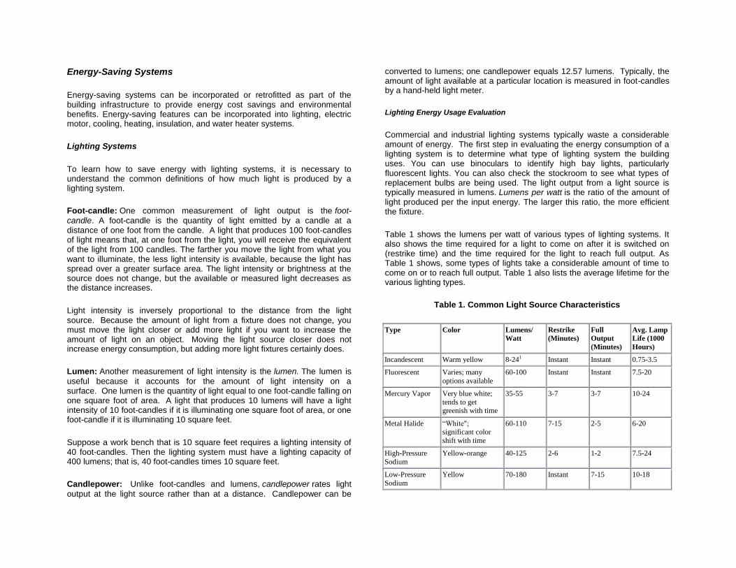
Commercial and industrial lighting systems typically waste a considerable amount of energy. The first step in evaluating the energy consumption of a lighting system is to determine what type of lighting system the building uses. You can use binoculars to identify high bay lights, particularly fluorescent lights. You can also check the stockroom to see what types of replacement bulbs are being used. The light output from a light source is typically measured in lumens. Lumens per watt is the ratio of the amount of light produced per the input energy. The larger this ratio, the more efficient the fixture.
Table 1 shows the lumens per watt of various types of lighting systems. It also shows the time required for a light to come on after it is switched on (restrike time) and the time required for the light to reach full output. As Table 1 shows, some types of lights take a considerable amount of time to come on or to reach full output. Table 1 also lists the average lifetime for the various lighting types.
Table 1. Common Light Source Characteristics
Type Color Lumens/
Watt Restrike
(Minutes) Full
Output
(Minutes)
Avg. Lamp
Life (1000
Hours)
Incandescent Warm yellow 8-241 Instant Instant 0.75-3.5
Fluorescent Varies; many
options available
60-100 Instant Instant 7.5-20
Mercury Vapor Very blue white;
tends to get greenish with time
35-55 3-7 3-7 10-24
Metal Halide “White"; significant color
shift with time
60-110 7-15 2-5 6-20
High-Pressure
Sodium
Yellow-orange 40-125 2-6 1-2 7.5-24
Low-Pressure
Sodium
Yellow 70-180 Instant 7-15 10-18

Light Emitting
Diode (LED)
Any color 75 Instant Instant 502
1The most common incandescent lamps yield approximately 17 lumens/watt.
2The useful life of an LED is defined as the time it takes for the initial light output to be reduced by 30%
One very common commercial lighting type is the fluorescent light. Table 2 shows that there is a considerable variation in the efficiency of fluorescent lights. For example, a T8 fluorescent lighting fixture uses only 56% of the energy consumed by a standard fluorescent light while producing the same light output.
Table 2. Variations in Fluorescent Lamp and Fixture Choices
Lamp Type Ballast Type Relative Energy Consumption
compared to standard lamp and
magnetic ballast
Standard Standard Magnetic 100%
Standard Efficient Magnetic 87%
Standard Electronic 75%
Efficient Standard Magnetic 90%
Efficient Efficient Magnetic 80%
Efficient Electronic 68%
T8 Matched Electronic 56%
Light-emitting diodes (LED) have been around since the 1960s. At first, they were only available in colors. In 1993, however, a white LED light was developed. Since then, technology has advanced significantly. Today LEDs are used in many applications such as tail lights, airport runway lights, flashlights, traffic lights, and other applications where an extremely long-life, high-efficiency light is needed. As shown in Table 1, LEDs are very efficient, providing 75 lumens per watt. They also have extremely long lives, since they degrade over time rather than to simply stop working. The useful life of an LED is defined as the time it takes for the initial light output to degrade by 30%, and that life is 50,000 hours. Therefore after 50,000 hours of operation, a typical LED still produces 70% of its light.
Selection of the proper light type and lighting level can save significant energy. For example, as Table 1 shows, low-pressure sodium lights provide up to 180 lumens per watt of energy consumed. Compare this to
incandescent lights, which produce at best only 24 lumens per watt of energy. Incandescent lights consume 7.5 times the energy of low-pressure sodium lights for the same lighting level. Less efficient lighting systems also give off more heat energy, which increases the air conditioning load.
As Table 2 shows, the choice of fluorescent lamp and ballast can have a significant effect on energy consumption. For example, suppose you change from standard fluorescent lamps with magnetic ballasts to energy-efficient T8 fluorescent lamps with electronic ballasts. By doing so, you can reduce energy consumption and waste heat rejected into the conditioned space by 44%, while still maintaining the same lighting level.
Lighting needs must also be considered when selecting the proper lamp type. For example, in low-use areas, suppose you replace high-pressure sodium lights with less efficient fluorescent lights. Although fluorescent lights are less energy efficient, they have an instant restrike time. Sodium lights, because they take so long to warm up, are frequently left on continuously, which can result in higher energy consumption. The longer restrike time for high-pressure sodium lights thus makes them a poor choice for low-use areas in terms of overall energy consumption.
To determine the required lighting level for a particular work area, use a hand-held light meter to measure the amount of available light. Hold the meter at work level. Refer to Table 3 for the recommended lighting level for the application. For additional information, see the Illuminating Engineering Society of North America (IESNA) guidelines athttp://www.iesna.org/.
Table 3. Common Lighting Requirements1
Type Foot-candles
Assembly and Inspection 20-50
Simple 50-100
Moderate 100-200
Complex 200-500
Very Complex 500-1000
Machine Shops 200-500
Control Room 20-100
Mechanical Room 20-50
Warehouse:

Inactive 5-10
Active:
Large Items 10-20
Small Items 20-50
Corridors and Lobbies 10-20
Office 40-100
1See IESNA guidelines for much more detail.
You will find that some areas typically have excessive lighting, particularly warehouse space, walk-in freezers, and hallways. Strategies you can use to reduce lighting include:
Removing lamps (for fluorescent fixtures, the ballast will still consume some energy).
Rewiring fixtures to allow partial to full lighting.
Installing new, efficient fixtures with a reduced design point for the lighting level.
Lighting level may be perceived as a "health and happiness" issue, which means that even if an area has higher lighting levels than recommended by IESNA, it may go against the local culture to reduce lighting.
The fluorescent fixtures of today are extremely rugged and versatile. These fixtures can operate in ambient temperatures down to 0°F, can be operated as Bl-level lighting, or can be dimmed without reducing the rated lamp life. Today‟s fluorescent fixtures provide flicker-free operation and can operate with total harmonic distortion of less than 5% and a power factor greater than 90%. Having T8 and standard fluorescent fixtures at the same facility may create problems, however. Although standard fluorescent lamps fit in T8 fixtures, the ballasts are not matched.
Replacing incandescent lamps with compact fluorescent lamps offers a quick and easy way to retrofit to more efficient lighting.
Replace high-bay incandescent fixtures with high-pressure sodium lamps in areas where the color of the light is not important. Some people might not like the yellow-orange light. This light color may also be unacceptable where good color recognition is required; for example, in a product inspection/grading area. Replace incandescent fixtures with higher-efficiency
metal halide fixtures in areas where color is important. Metal halide lamps offer a white light preferred by some; however, they are not as efficient as high-pressure sodium lights.
Mercury vapor lights are popular because of their long lamp life, but these lamps are not energy efficient as they age. Their lumen output decreases with age, while they continue to consume the same amount of energy. Replace mercury vapor fixtures with higher- efficiency lighting fixtures.
Motor Systems
Electric motors have a relatively constant power factor and efficiency down to approximately 50% of full load (within +1- 5%). Below this point, power factor and efficiency degrade rapidly. Larger motors typically are more efficient than smaller motors.
The installation of variable speed drives may induce harmonics into the electrical distribution system. A system with many capacitors installed can be particularly vulnerable unless tuned by a professional. Some installations are relatively insensitive to this problem, while others are very sensitive. Be particularly careful if a facility already has experienced power quality problems, such as equipment shutdown, computer glitches, unusual motor or light ballast failures, overheated transformers or capacitors, high 3-phase neutral currents, or significant neutral-to-ground voltage. Also be careful in facilities that have heavy rectifier loads, such as from charging equipment or induction furnaces, or significant computer and other electronic loads. Note that existing motors can be overheated by variable speed drives.
Common strategies for improving the energy efficiency of motor systems include:
Replacing standard motors with high-efficiency motors. For 5 to 30 hp motors, estimate a 5 to 3.5% increase in efficiency. For 40 to 125 hp motors, estimate a 3.5 to 3% increase, and for motors 150 hp and above, estimate a 2% increase.
Replacing eddy current drives with solid-state, variable-speed drives. Eddy current drives are an older, less efficient method of achieving variable speed control. Eddy current clutches can be high-maintenance items, and replacement parts are expensive and difficult to locate.
Downsizing motors to achieve higher efficiency. Motors often are progressively upsized in a facility as they are replaced. If a motor of

the same size is not available, the next size up is typically installed, usually just to be on the safe side. If a motor consistently operates at less than half of full load, however, it is not operating efficiently and is a candidate for a downsizing assessment. Motors consume the least amount of energy when they operate at their highest efficiency. For most motors, this is from 75 to 110% of their rated load. As motor loading drops below 50%, efficiency and power factor drop rapidly. Motor loading determined in kilowatts rather than amperage is preferred because kilowatt readings take into account the changes in power factor and amperage that occur as motor loading changes.
Cooling Systems
Cooling Towers
Energy can be saved on cooling tower installations by upgrading fans and improving the tower structure. Cooling tower fans typically run at a constant speed of 60 Hz, or else a two-speed motor may drive them. Significant energy savings can be achieved by installing variable speed drives on the cooling tower fan motors. The amount of savings depends on ambient weather conditions (wet bulb temperature) at the tower location and the cooling loads placed on the tower.
Cooling towers work by forcing or drawing air through the tower and using fans to cool the incoming water. To make the fans more energy efficient, consider installing variable speed drives that vary the fan speed while maintaining the set-point temperature of the cooling water leaving the tower. When cooling demands are low, such as during second or third shifts, tower fans can operate at reduced speed and thereby consume less energy. Cooling tower fans can even be turned off when ambient air conditions alone will sufficiently cool the water without the aid of fans. When fans are off, energy consumption is significantly reduced to just the cost of circulating the water through the tower.
The following energy savings opportunities should be evaluated for each cooling tower:
Replace the tower fill material with cellular film fill to improve the heat transfer efficiency.
Install non-clogging, non-corroding spray nozzles to improve water distribution through the tower.
Install energy-efficient airfoil fans.
Install energy-efficient motors on the cooling tower fans and pumps.
Cooling tower optimization reduces energy consumption and may also result in colder water for cooling. Reducing the temperature of the cooling water increases the efficiency of the chiller. The improvement in chiller performance is about 1% for each one-degree drop in chiller water temperature.
One of the most common and inefficient methods to control a fan or pump is to restrict its flow. As the pressure is increased, the flow is reduced. However, the work required to deliver the reduced flow is greater than would otherwise be required if a smaller pump or fan were used. Rather that restricting the flow to create additional pressure drop and thereby reduce the flow, a properly sized pump, fan, or blower will save money. If variable flow is needed, then replace the throttle control (variable restriction) on the pump or fan with a solid-state variable speed drive.
Although less common, bypass control can be an extremely inefficient method for controlling flow and should also be replaced with solid-state variable speed drive control. Variable speed drives can provide significant energy savings.
Savings estimates for installing variable speed drives obviously vary greatly with conditions. However, variable speed drives frequently pay off in a year or two if they replace a throttle control that operates at 60 to 70% of full flow or less most of the time. The impact on the fan or pumping system due to variations in speed should be evaluated when considering this measure. Be careful when applying variable speed drives to turbine pumps. Damaging harmonic vibration can develop at certain operating frequencies. In addition, turbine, centrifugal, and axial vane pumps and compressors are typically designed to be efficient over a very narrow operating range, so variable speed drives may have very limited applicability.
Evaporative Cooling Systems
When water evaporates from a liquid to a vapor, it provides about 1000 Btu of cooling per pound of water. In areas where humidity is low but ambient temperature is high, this type of evaporative cooling can be used to cool interior spaces. However, it does raise the humidity in the interior space.

Cooling devices that rely on this technology are commonly referred to as “swamp coolers”. In a typical swamp cooler, water is misted or sprayed into the air flow to cool the air. Another method is to place a porous, wetted surface into the air flow.
Because humidity is elevated by this process, the approach works only when the original humidity level is well below the maximum humidity level that still allows comfort. Humidity must be monitored to keep it at levels low enough to prevent mold growth, which typically is below 55% relative humidity. The same concept is used for outdoor misting systems, which cool outdoor areas.
Another emerging area of evaporative cooling is roof ponds. A large thermal load on a building is typically from the roof. A water pond on the roof results in cooler roof temperatures, because the water cools itself as it is evaporated by the solar load or the wind. Simply spraying water on the roof has a similar effect.
Passive Cooling Systems
Passive cooling systems should always be used when possible, since they use no energy and have no parts to fail. The simplest passive cooling system is to use shade trees around the structure. Opening a window at night or using an automatic economizer system (to let outside air in when it is cooler during cooling season) also saves energy. Solar chimneys are popular in some areas. They use the natural rising of warmer air in the structure to remove heat and draw cooler air into the structure at ground level. Decorative window awnings and screened porches also provide a shelter from direct solar insolation and thereby lower thermal loads.
Thermal storage is another method of lowering either the heating or cooling load. Phase-change storage systems are used in commercial structures to shave the peak heating or cooling load from the system, thus allowing a smaller unit to be used. Churches are a common location where this technology is used. For example, a smaller chiller unit can operate throughout the evening to make ice. The ice is then used to chill the water, in addition to the chiller, during the warmest part of the day or when the church is full of people. A common passive thermal storage method is to construct residential structures with energy storage materials. For example, cement block residences take longer to heat up in the sun‟s heat compared to a typical wood frame construction.
Water Source and Ground Loop Heat Pump Systems
Air conditioning systems pump heat from the indoors (evaporator) to outdoors (condenser) to provide cooling, thus the term heat pump cooling. Likewise, a vapor compression system can be reversed to pump heat from the outdoors (evaporator) to the indoors (condenser) to provide heating in the winter. From a performance standpoint, the cooler the condenser during cooling, the greater the performance; that is, the greater the amount of cooling for a set amount of electrical consumption. The goal is always to operate the condenser such that it is as cool as possible. A water-cooled condenser can be used instead of an air-cooled condenser. This method is used in chillers that employ cooling towers, because the water that evaporates in the cooling tower lowers the remaining water temperature. This action results in a cooler operating condenser and thus greater performance.
A cooling tower for a residential or small commercial application is not practical. However, another way to dramatically lower the condenser temperature is to use groundwater, lake water, or the ground itself to cool the condenser. Lake water, well water, and groundwater are always cooler than the air in summer and warmer that the air in winter. Therefore, cooling a condenser with water from one of these sources during air conditioner operation may save energy and money. Whether or not there are actual energy savings depends on the energy expended to pump the water through the condenser coil. Other costs could include those related to the maintenance and life-cycle of components. For such components as pumps, piping, and the water-cooled condenser, biofouling or corrosion may be a problem.
If a source of water is not available, then ground-loop piping can be buried in the ground to extract cooling from the soil itself. A ground loop is a large loop of piping, buried in the ground, that (in cooling mode) draws energy from the soil adjacent to the piping. The water circulated thought the ground-loop pipe is used to cool the condenser of an air conditioner. Because thermal contact with dry soil is not very good, a significant amount of ground-loop piping must be used. A thermal engineer must calculate the exact amount. The heating and cooling of the ground-loop pipe has been shown to compress the soil adjacent to the piping. In some cases, this compression results in a small air gap between the piping and the soil, which reduces the performance of these systems over time.

Insulation Systems
Insulation should be used to save energy in three critical systems:
The domestic hot water heater or domestic water heater storage tanks.
The air conditioning ductwork (in un-insulated areas).
The structure.
Domestic Water Heater Insulation
Heating water for domestic purposes is estimated to consume 10 to 25% of the total energy used in an average home. Restaurants, commercial laundries, and other high-volume water users consume even more energy. While tankless water heaters are becoming more popular, the most common type of domestic water heater still is the water storage water heater. In these systems, 40 to 120 gallons or more of hot water is stored until it is needed. This hot water is continually losing heat to the surroundings. The rate of heat loss depends on the water temperature, the surrounding air temperature, and the amount and quality of the insulation on the water tank (its overall R-value). Unless the water heater already has an overall R-value of 24, adding insulation to the tank can reduce standby heat loss by 25 to 45% and can save up to 11% in energy costs.
Air Conditioning Duct Work Insulation
If air conditioning duct work in unconditioned areas is not insulated, heat will be conducted into the air duct. Heat conduction will reduce the cooling capacity of the air flowing through the ducts and will thereby waste considerable energy. Condensation is another significant problem with uninsulated duct work in unconditioned areas. If the external surface of the uninsulated duct work is cooler that the dew point temperature, the moisture in the unconditioned space will condense on the ductwork. This condensation will result in further energy losses, possible water damage, and the formation of mold.
Structure Insulation
By far the best method for reducing energy consumed for heating or cooling a structure is to eliminate air leaks and assure the structure is properly insulated. Heating and cooling accounts for 50 to 70% of the energy used in the average American home. Inadequate insulation and air leakage are
leading causes of energy waste in most homes. Insulation is cost effective, and it is one of the best ways to save money on energy bills and save our nation's limited energy resources. Insulation also reduces thermal variation in a structure. A uniform temperature throughout a structure makes occupants more comfortable. It also makes walls, ceilings, and floors warmer in the winter and cooler in the summer. The amount of energy saved with insulation depends on several factors including climate; size, shape, and construction of the structure; and occupant living habits.
Heat flows naturally from a warmer to a cooler space. In winter, heat moves directly from all heated living spaces to the outdoors and to adjacent unheated attics, garages, and basements-wherever there is a difference in temperature. During the summer, heat moves from outdoors to the house interior. To maintain comfort, the heat lost in winter must be replaced by your heating system, and the heat gained in summer must be removed by your air conditioner. Adding insulation to ceilings, walls, and floors decreases the heating or cooling needed by providing an effective resistance to the flow of heat.
Types of Insulation. Batts, blankets, loose fill, and low-density foams all
work by limiting air movement. (These products may be more familiarly called fiberglass, cellulose, polyicynene, and expanded polystyrene.) The still air is an effective insulator because it eliminates convection and has low conduction. Some foams, such as polyisocyanurate, polyurethane, and extruded polystyrene, are filled with special gases that provide additional resistance to heat flow. Reflective insulation works by reducing the amount of energy that travels in the form of radiation.
R-Value Rating. Insulation is rated in terms of thermal resistance, called R-
value, which indicates the resistance to heat flow. The higher the R-value, the greater the insulating effectiveness. The R-value of thermal insulation depends on the type of material, its thickness, and its density. In calculating the R-value of a multi-layered installation, the R-values of the individual layers are averaged.
Note, however, that insulation that is compressed will not provide the full rated R-value. This can happen if heavier (denser) insulation is installed on top of lighter insulation in an attic. It also happens if you place batts rated for one thickness into a thinner cavity, such as placing R-19 insulation rated for 6.25 inches into a 5.5-inch wall cavity.
Insulation Placement. Insulation placed between joists, rafters, and studs
does not retard heat flow through those joists or studs. This heat flow is

called thermal bridging. The overall R-value of a wall or ceiling (where there is thermal bridging) will be lower than the R-value of the insulation itself. That is why it is important that attic insulation cover the tops of the joists and why insulated sheathing is sometimes used on walls. The short-circuiting through metal framing is much greater than that through wood-framed walls, because of the lower R-value of metal studs compared to wood studs. Sometimes, the overall R-value of an insulated metal stud wall can be half the R-value of the insulation.
The different forms of insulation can be used together. For example, you can add batt or roll insulation over loose-fill insulation, or vice-versa. Usually, material of higher density (weight per unit volume) should not be placed on top of lower density insulation that is easily compressed. Doing so will reduce the thickness of the material underneath and thereby lower its R-value. There is one exception to this general rule. When attic temperatures drop below 0°F, some low-density, fiberglass, loose-fill insulation installations may allow air to circulate between the top of your ceiling and the attic, decreasing the effectiveness of the insulation. You can eliminate this air circulation by covering the low-density, loose-fill insulation with a blanket insulation product or with a higher-density loose-fill insulation.
Reflective Insulation. Reflective insulation systems are fabricated from
aluminum foils with a variety of backings such as kraft paper, plastic film, polyethylene bubbles, or cardboard. The resistance to heat flow depends on the heat flow direction, and this type of insulation is most effective in reducing downward heat flow. Reflective systems are typically located between roof rafters, floor joists, or wall studs. If a single reflective surface is used alone and faces an open space, such as an attic, it is called a radiant barrier. Radiant barriers are installed in buildings to reduce summer heat gain and winter heat loss.
Steam Heating Systems
The following are energy conservation tips for steam heating systems.
Small leaks in a steam system can waste significant energy. These leaks can be due to faulty seam traps. A 1/8-inch hole in a steam system will lose 600,000 Btu per year of steam in a 100 psi system.
Verify that the system is operating with the correct stack temperature. There is a 1% decrease in boiler efficiency for every 40°F increase in stack temperature. Optimum stack temperature is typically 50°F to 100°F above saturated steam temperature at the boiler operating pressure. A record of the stack temperature after
boiler tuning offers a more accurate means to determine the optimum stack temperature. Excessively high stack temperatures suggest poor heat transfer (dirty heat exchanger surfaces) or too much combustion air. Stack temperatures lower than 275ºF can lead to corrosive condensation.
Clean the boiler to remove water-side and fireside fouling. Soot can usually be removed with a brush during regular maintenance. Scale on the water side may require extensive chemical treatment if deposits are severe.
As water is evaporated to steam, solids in the water remain in solution. To keep dissolved solids from building up to excessive levels, the boiler water is drained and replaced with fresh water. This is called "blow-down." The difference in temperature between the replacement water and the hot boiler water represents an energy loss. To minimize this loss, blow-down should be set to the minimum required to keep dissolved solids at an acceptable level. The rate of continuous blow-down depends on the quality of the feed water and the amount of condensate return. Reducing the blow-down will also reduce the amount of water treatment chemicals required.
Steam traps are usually designed on the basis of a maximum back-pressure rating. This rating is determined by dividing the outlet pressure by the inlet pressure to obtain absolute pressure (psia). If the back pressure of the present system is greater than the original design pressure, the trap is not able to fully close, and can fail in the open position. When these traps fail open, they blow steam into the return system. This steam increases the back pressure on other traps in the system, causing them to fail. When the steam is induced into the return piping, the vapor flows over the condensate, eventually causing enough turbulence to create a mass or "slug" of condensate that fills the pipe. The condensate slug can travel throughout the piping system at the same velocity as the steam until it encounters a sudden change in direction. This energy is transferred into a force referred to as "water hammer". It can be difficult to identify traps that are leaking, failed open, or failed closed. When properly designed and maintained, steam traps remove the condensate from the steam and purge air. If your customer has a steam heating system, encourage them to initiate a program to identify and repair traps that are malfunctioning and to consider installing continuously discharging thermostatic steam traps.

Vapor Compression Systems
The following are energy conservation tips for vapor compression air conditioning, refrigeration, and freezer systems.
The energy consumed by the compressor drops by 1 to 1.5% for every 1°F drop in compressor head pressure.
The energy consumed by the compressor drops by 2 to 3% for every 1°F increase in suction pressure.
A two-stage vapor-compression system has three separate pressures maintained by high- and low-stage compressors. Choose the intermediate pressure so that each compressor has approximately the same pressure ratio to minimize compressor energy use.
Eliminate the use of back pressure regulators (BPRs) to control suction pressures for accommodating a significant portion of the load. BPRs control various refrigeration loads on a single system. Loads requiring a lower suction pressure could be separated from loads requiring a higher suction pressure.
Consider load shifting during periods of high energy use, or thermal storage during periods of low energy use, to reduce total energy demand.
Consider installing additional condensing capacity to reduce discharge pressure.
Maintain cooling towers as described in the section, Cooling Towers. Water evaporates as it absorbs heat from the condensing refrigerant. The heat exchange surface must be clean and free of corrosion. Air must pass through freely for efficient heat transfer. Water should be treated to reduce scale and corrosion and to reduce biological growth.
Purge non-condensable gases. Non-condensable gases, such as air, reduce the effective surface area of the condenser used to condense refrigerant vapor, thereby decreasing heat exchanger efficiency. In general, non-condensables enter the system when the low-stage suction pressure is less than atmospheric pressure, or when a system is not properly evacuated prior to charging.
Evaporator coils must be free of ice for maximum heat transfer, but to be energy efficient, avoid excessive defrost times.
Chapter 3 - HVAC System Design
The HVAC system includes all heating, cooling, and ventilation equipment serving a building: furnaces or boilers, chillers, cooling towers, air handling units, exhaust fans, duct work, filters, and steam (or hot water heating water) piping. Most of the HVAC discussion in this course applies to central HVAC systems.
A properly designed and functioning HVAC system provides thermal comfort (cooling and dehumidification or heating and humidification) and filters the air. Commercial HVAC systems also distribute adequate amounts of outdoor air to meet the ventilation needs of all building occupants and to isolate and remove odors and contaminants (through pressure control and exhaust fans).
Thermal Comfort Considerations
A number of variables interact to determine whether people are comfortable with the temperature of indoor air. The activity level, age, and physiology of each person affect the thermal comfort requirements of that individual.
Uniformity of temperature is important to comfort. The heating and cooling needs of rooms within a single zone may change at different rates. As a result, rooms that are served by a single thermostat may be at different temperatures. In addition, temperature stratification caused by convection-the tendency of light, warm air to rise and heavier, cooler air to sink-can affect uniformity. If the air is not properly mixed by the ventilation system, the temperature near the ceiling can be several degrees warmer than at floor level. Even if the air is properly mixed, uninsulated floors over unconditioned spaces can create moisture problems and even discomfort in some climate zones.
Large fluctuations of indoor temperature can also occur when the temperature control has a wide dead band (a temperature range within
which neither heating nor cooling takes place). To alleviate this problem, adjust the thermostat to narrow the dead band, if possible. Otherwise, replace the thermostat with one that has a narrower dead band or an improved anticipating control algorithm, such as a PID controller.
Humidity is a factor in thermal comfort. Raising relative humidity reduces the ability to lose heat through perspiration and evaporation, so that the effect is similar to raising the temperature. Humidity extremes can also create other

indoor air quality problems. Excessively high or low relative humidity can produce discomfort, while high relative humidity can promote the growth of mold and mildew. To prevent mold and mildew, the relative humidity must be less than 55% in all areas of the building. To reduce humidity, you can install a device like the Mainstream Humidity Control Board. This device is added to an existing system and uses the air-conditioning unit and the backup electric heat simultaneously to lower the humidity without making the conditioned space too cold.
Radiant heat transfer may cause people located near very hot or very cold surfaces to be uncomfortable, even though the thermostat setting and the measured air temperature are within the comfort range. Buildings with large window areas sometimes have acute problems of discomfort related to radiant heat gains and losses. Areas of discomfort can shift during the day as the sun angle changes. Large vertical surfaces can also produce significant natural convection flows, which can result in complaints of drafts. Adding insulation to walls helps to moderate the temperature of interior wall surfaces. Closing curtains or blinds reduces heating from direct sunlight and isolates building occupants from exposure to window surfaces (which, lacking insulation, are likely to be much hotter or colder than the walls).
Design Considerations
The goal in HVAC system design is to provide proper airflow, heating, and cooling to each room. The HVAC installer must test every structure either at rough or final. At rough, without the air handler installed, maximum allowable leakage (calculated as percent of total fan flow, and cfm leakage measured with HVAC system pressurized to 25 Pa) is 4%. At rough or final, with the air handler installed, maximum allowable leakage is 6%.
When designing an HVAC system, consider the following recommendations.
Install system such that the static air pressure drop across the handler is within manufacturer design specifications.
Ensure sealed supply and return ductwork will provide proper airflow while preventing air from entering the HVAC system from polluted zones (e.g., fumes from autos and stored chemicals, and attic particulates).
Create balanced airflows between supply and return systems to maintain neutral pressure in the home.
Minimize duct air temperature gain or loss between the air handler and supply registers, and between return registers and the air handler.
For furnaces, ensure proper burner operation and proper draft.
Install equipment and ducts in accordance with manufacturers‟ specifications as well as installation requirements and procedures from the Uniform Mechanical Code, the Air Diffusion Council, and SMACNA.
Charge the system appropriately, and verify charge with the evaporator superheat method or subcooling method (or an equivalent method).
Test the system to ensure that it performs properly: o Does not leak substantially. o Has proper air handler fan flow. o Has proper supply and return air flows. o Has proper plenum static pressures.
Minimum Materials Specifications
The following are minimum materials specifications recommended to achieve a substantially tight installation that will last.
All Materials
Shall have minimum performance temperature ratings per UL-181 (ducts), UL-181A (closure systems for rigid fiberglass ducts), UL-181B (closure systems for flexible ducts), and/or UL-181BM (mastic). Butyl-backed tape may also be used to seal ducts, duct board, and metal.
Shall have a flame spread rating of no more than 25 and a maximum smoke developed rating of 50 (ASTM E 84).
Factory-Fabricated Duct Systems
Shall include UL-181 listed ducts with approved closure systems including collars, connections, and splices.
Shall use UL-181A listed pressure-sensitive and heat-activated tapes in the manufacture of rigid fiberglass ducts.
Shall use UL-181B (tape) or UL-181BM (mastic) listed pressure-sensitive tapes and mastics in the manufacture of flexible ducts.

Field-Fabricated Duct Systems
Shall include UL-181 listed factory-made ducts in any field-fabricated duct systems.
Shall have the following requirements for mastic sealants and mesh:
o Sealants shall be UL-181BM listed, non-toxic, and water resistant.
o Sealants for interior applications shall pass ASTM tests C-731 (extrudability after aging) and D-2202 (slump test on vertical surfaces).
o Sealants and meshes shall be rated for exterior use. o Sealants for exterior applications shall pass ASTM tests
C-731, C-732 (artificial weathering test), and D-2202.
Shall have the following requirements for pressure-sensitive tapes: o Cloth-backed, rubber-adhesive tapes (typical duct tape)
shall not be used even if UL-181B rated. o Tape used for flex duct shall be UL-181B listed or be
aluminum-backed butyl adhesive tape (15 mil. minimum). o Tape used for duct board shall be UL-181A listed and so
indicated with a UL-181A mark, or shall be aluminum-backed butyl adhesive tape (15 mil. minimum).
Shall have the following requirements for draw bands: o Shall be either stainless-steel, worm-drive hose clamps or
UV-resistant nylon duct ties. o Shall have a minimum performance temperature rating of
165 °F (continuous, per UL-181A-type test) and a minimum tensile strength rating of 50 pounds.
o Shall be tightened, as recommended by the manufacturer, with an adjustable tensioning tool.
HVAC Design Methodology
Use the following methods as a guide for efficient HVAC system design and installation.
Calculate Loads and CFM
Use ACCA Manual J Load Calculation or equivalent.
Calculate heat loss and heat gain for each room.
Use the total of all the room loads to determine overall system requirements.
Lay Out Air Distribution System
Lay out the duct system on the floor plan. Determine register positions and duct paths to optimize room air circulation and minimize actual duct length. Determine equivalent lengths of fittings, bends, etc.
In determining duct paths, account for locations and directions of joists, roof hips, fire walls, and other potential obstructions.
Plan duct paths to avoid sharp turns of flex duct that will kink the duct.
Plan duct paths to drop conditioned cool air at warmest place in the room, which is typically along exterior walls.
Plan duct path to accommodate air flow to the return duct without short circuiting.
If hallways are used as part of the return air flow path, allow sufficient space under doors for return air flow. Measure air flows with doors open and with doors closed. Assure the system is properly balanced for either case.
Size Air Distribution System
Use ACCA Manual D Duct Design or equivalent method.
Calculate correct air flow rate (in cubic feet per minute, cfm) for each room and total air flow rate for the building. Size both the supply and return duct work for this flow rate.
Size ducts according to Manual J loads, Manual D air flows, and final layout on plans.
Choose registers to optimize air distribution and duct static pressure.
Size and locate returns to optimize air flow per ACCA methods.
For return-filter grills, use ACCA methods to calculate minimum return filter area.
Select System
Determine proper system size. Consider both sensible cooling load and latent moisture removal.
Determine equipment capacity such that it is not more than 10% larger than the total design load.
Select high-efficiency equipment.

Chapter 4 - HVAC System Installation
The goal in HVAC system installation is to provide a duct system that is substantially airtight and that will provide proper airflow to each room of the house. Use the following fabrication and installation guidelines to achieve this goal.
General Guidelines
Construct ducts, plenums, and fittings of galvanized metal, duct board, or flexible duct. Do not use building cavities as a duct or plenum without a sealed duct board or metal liner.
Ensure that the air handler box is airtight.
Locate air filters so that they are easily accessible for replacement. When installing new equipment, position the evaporator coils so that they are easily accessible for cleaning.
Configure and support air ducts to prevent the use of excess material, to prevent dislocation or damage, and to prevent constriction of ducts below their rated diameter.
Avoid making flexible duct bends across sharp corners, and avoid incidental contact with metal fixtures, pipes, or conduits that can compress or damage the ductwork.
Avoid flexible duct bends that exceed 90 degrees unless specified in the design.
Ensure sheet metal collars and sleeves are beaded to hold draw bands.
Fabrication and Installation Guidelines
Use the following fabrication and installation guidelines to achieve an air-tight duct system.
All Duct Types
Seal all joints and seams of duct systems and their components with mastic or mastic and embedded mesh. This method is preferred over aluminum-backed butyl adhesive tape or pressure-sensitive tape, even though these tapes are approved for use by the duct manufacturer and meet UL-181 specifications. Never use cloth-backed rubber-adhesive tapes to attach or seal ducts.
Seal junctions of collars to distribution boxes and plenums with mastic.
Use all sealants in strict accordance with manufacturer's installation instructions and within sealant moisture and temperature limitations.
Apply all tapes used as part of duct system installation to clean, dry surfaces and seal with manufacturer's recommended amount of pressure or heat. If oil is present, prepare taped surfaces with a cleaner/degreaser prior to application.
Seal all register boxes to the drywall or floor with caulking or mastic (optional but recommended).
Flexible Ducts
Join flexible ducts by a metal sleeve, collar, coupling, or coupling system. At least 2 inches of the beaded sleeve, collar, or coupling must extend into the inner core while allowing a 1-inch attachment area on the sleeve, collar, or coupling for the application of tape.
Mechanically fasten the inner core of flexible ducts to all fittings, preferably using draw bands installed directly over the inner core and beaded fitting. If not using beaded sleeves and collars, then fasten the inner core to the fitting using #8 screws equally spaced around the diameter of the duct. Install so as to capture the wire coil of the inner liner (three screws for ducts up to 12 inches in diameter, and five screws for ducts over 12 inches in diameter).
Seal the inner core to the fitting with mastic. Avoid using tape.
If approved tape is to be used then, apply tape (for sealing the inner core) with at least one inch of tape on the duct lining and one inch of tape on the fitting of the flange, each wrapped at least three times.
Seal the outer sleeve (vapor barrier) at connections with a draw band. Avoid using tape instead of the draw band, but if tape is to be used, then secure it with three wraps of approved tape.
Assure the vapor barrier is complete. Seal all holes, rips, and seams with mastic.
Metal Ducts and Plenums
Clean and seal metal-to-metal connections in accordance with manufacturer's specifications.
Seal openings greater than 1/16 inch with mastic and mesh.
Seal openings less than 1/16 inch with mastic.

Pay special attention to collar connections to duct board and/or sheet metal; seal around these connection with mastic.
Seal connections between collars and distribution boxes with mastic.
Mechanically fasten round ducts with at least three equally spaced #8 screws (three screws for ducts up to 12 inches in diameter, and five screws for ducts over 12 inches).
Ensure crimp joints have a contact lap of at least 1½ inches.
Mechanically fasten square or rectangular ducts with at least one screw per side.
Duct Board
Seal duct board connections with mastic. Adhesive or UL-181A listed pressure-sensitive or heat-activated tape does not hold up as well over long periods and can result in duct leakage.
Duct Support
Install supports per manufacturer specifications or per UMC requirements.
Ensure supports for flexible ducts are spaced at no more than 4-foot intervals.
Support flexible ducts by strapping having a minimum width of 1½ inches at all contact points with the duct.
Ensure supports do not constrict the inner liner of the duct.
Allow a maximum of one-half inch of sag per foot between supports
of flexible ducts.
Allow flexible ducts to rest on ceiling joists or truss supports as long as they lie flat and are supported at no more than 4-foot intervals.
Boots
After mechanically attaching the register boot to floor, wall, or ceiling, seal all openings between the boot and floor, wall, or ceiling with mastic.
Air Handler
Seal openings greater than 1/16 inch with mastic and mesh.
Seal openings less than 1/16 inch with mastic.
Seal any unsealed access doors with UL-181A listed tape.
Refrigerants
Test the system refrigerant to ensure it is properly regulated. For systems with fixed metering devices (such as capillary tubes or orifice plates), use the evaporator superheat method. For systems with thermostatic expansion valves, use the subcooling method. Ensure the following.
Indoor coil airflow must be greater than 350 cfm/ton.
Refrigerant system evacuation must be complete (all non-condensables must be removed from the system).
In hot, dry climates, ensure the system is within range of the superheat charging chart, or use another approved method to prevent overheating.
Furnace Combustion
Check each chamber for correct flame.
Check for proper drafting.
System Performance
Test the following to make sure the HVAC system is installed properly. Test to make sure:
Room-by-room airflows are correct.
Total supply is as designed.
Total return = total supply.
Ducts, plenum, and air handler are tight.
Static pressure is correct.
Test the system to ensure that it performs properly by:
Verifying HVAC equipment sizes installed are those specified.

Measuring duct leakage.
Measuring either fan flow or supply and return flows and plenum static pressures.
System Sensibility
Check the following to ensure that the air conditioner sensible capacity is no more than 15% greater than the calculated sensible load:
Fan flow must be greater than 350 cfm/ton.
The correct size air handler must be installed.
Duct System Leakage
Ensure that the duct system does not leak substantially by checking the following items.
For a rough system, including both supply and return but without the air handler, ensure leakage is not more than 4% of specified fan flow (cfm leakage measured with HVAC system pressurized to 25 Pa).
For finished installations, including supply, return, air handler, and finished registers, ensure measured leakage is less than 6% of nominal fan flow or measured fan flow, or of measured return flow (cfm leakage measured with HVAC system pressurized to 25 Pa).
Measure air handler air flow and static pressure across fan, and ensure that total air handler output is within 5% of design and manufacturer specifications at a static pressure within 0.1 in water of design.
Measure room-by-room airflows to ensure that each register is within 15% of design airflow and that the entire supply is within 5% of design.
Measure return air flow to ensure it is within 5% of total supply airflow.
Test static pressure drop across blower to ensure it is within 0.1 in water of design and manufacturer specifications.
Duct leakage can be determined using a pressurization or depressurization technique. For details, see ASHRAE Standard 152P or other commercially available duct pressurization or depressurization devices.
Duct leakage to unconditioned space can be determined with the house pressurization or LBL simplified technique. For details, see CEC report P400-91-031CN, Section Six.
To measure fan flow, supply flow, and return flow measurements, see Minneapolis Duct Blaster™ manual (or equivalent). Alternatively, for supply and return flows, use a calibrated flow hood. Do not use a pitot tube or any type of anemometer to determine these air flows.
Measure static pressure drop across the fan by using static pressure probes in the return plenum and in the supply plenum.
Chapter 5 - HVAC System Servicing
Probably the most effective means of saving energy in an existing system is to use proper preventive maintenance servicing techniques. This chapter is an excerpt from Mainstream Engineering Corporation‟s Preventive Maintenance Technician (PM Tech) manual and provides information pertinent to a discussion of green practices in HVAC system servicing and energy conservation.
There are essentially three subsystems to an operating vapor compression system: the refrigerant circuit subsystem, the air-side subsystem, and the electrical subsystem. Each of these subsystems must be serviced regularly to maintain maximum efficiency.
Refrigerant Circuit Subsystem
The refrigerant circuit subsystem contains four basic components: the evaporator, condenser, expansion device, and compressor. The refrigerant circuit also contains other key components such as:
The filter-drier, which serves to remove acid, water, and other
impurities from the refrigerant. Even if you have not added a filter-drier, there is usually a small copper-spun drier that is installed by the manufacturer. This filter-drier captures any moisture that may have been added during system fabrication and charging in the factory. On any split system, a filter-drier should always be added, even if a factory-installed drier is present. Split systems are prone to more leaks because of the field-installed piping.

A liquid receiver, which holds a reservoir of excess refrigerant.
This excess compensates for the density changes of refrigerant during cold or warm weather. This excess also allows the system to operate with a small loss in charge. The liquid receiver is sometimes simply incorporated into the condenser by over-sizing the condenser. In this case, the last few rows of the condenser act as a liquid receiver.
Service access valves, or means for attaching the service
manifold.
The refrigerant circuit may also contain other components which are not necessary in all applications, such as:
A suction line accumulator, upstream of the compressor suction
(inlet), to trap liquid refrigerant that might be returning to the compressor.
A reversing valve, which changes the direction of flow in a heat
pump, to switch the operation from heating to cooling.
Vibration isolators, to isolate the compressor‟s vibration from the
remaining plumbing and lower the stress and strain on the tubing.
A muffler, to reduce the noise generated by the compressor.
A sight glass, upstream of the expansion device, to verify a
complete charge, and often to check for moisture (if equipped with a moisture indicating paper).
Typical Mainstream QwikProducts that might be used on the refrigerant circuit to improve performance or increase life are:
QwikCheck® on the low-side service valve, to identify potential acid problems.
QwikShot® Acid Flush, to remove acid in the system by accelerating the transport of acid to the filter-drier.
Qwik System Flush® to remove contaminants after a burnout or during a system change-out (for example, a change-out from an HCFC refrigerant, such as R-22, to an HFC refrigerant, such as R-410A).
Air-Side Subsystem
The air-side subsystem contains two critical components: the evaporator blower and the condenser fan. The evaporator blower is part of the indoor air
system, and the condenser fan is part of the outdoor air section. Other key air-side subsystem components are:
The indoor air filter, condensate drain pan, and condensate drain line. A clogged indoor air filter causes reduced indoor
airflow, resulting in a lower evaporator operating temperature. The lower temperature increases the strain on the compressor because of the higher operating pressure ratio. The greater strain results in excess energy consumption and possibly cooler compressor operation or even premature failure of the compressor. Cooler compressor operation can result in liquid slugging, decreased oil viscosity, and increased compressor wear.
The condenser pad and outside fan grill. The fan grill keeps
debris from clogging the condenser airflow path. The condenser pad serves as a mounting platform to level the unit and also lifts the outdoor section above the soil. This separation minimizes entrainment of soil into the condenser and keeps the condenser coil away from string-edgers.
Typical Mainstream QwikProducts that might be used on the air-side subsystem to improve performance or increase life are:
QwikClean® Foaming Coil Cleaner, to clean and degrease the evaporator coil, thereby improving heat transfer and airflow. It also cleans the condenser coil and aids in the removal of corrosion products, thereby improving heat transfer and outdoor airflow.
QwikTreat™, to keep the condensate pan free from scum and the condensate drain line flowing freely.
QwikTreat Dispenser to allow the homeowner to maintain a free-flowing condensate line between service calls.
PuraClean® Filter Spray, applied to the air filter, to improve filter performance, keep the indoor air clean, and prevent fouling of the evaporator coil.
Electrical Subsystem
The electrical subsystem typically consists of the low-voltage control circuit and the line-voltage power circuits. Key components of the electrical subsystem include:

A transformer to convert the supply-line voltage to the 24 VAC
power used in the low-voltage control circuit.
A compressor contactor which, when closed, provides line power
to the compressor (and the condenser fan in a split system).
An evaporator blower motor contactor, to provide line power to
the evaporator blower motor.
A thermostat or other control device.
High-pressure and low-pressure cut-off switches that open the
low-voltage control circuit when system pressure is too high or too low. Excessively high pressures can be caused by a clogged or failed condenser fan, a clogged refrigeration circuit, a dirty condenser, an overcharged system, or operation outside of the system‟s operating range. Low pressures can be caused by insufficient charge, a clogged or failed evaporator fan, a dirty evaporator, or operation outside of the system‟s operating range.
Run and start capacitors, and a starting relay, to increase the
starting torque of single-phase motors. Note that both the run and start capacitors are wired into the start windings of single-phase motors. A start capacitor only remains in the electrical system during starting, whereas a run capacitor is always wired into the start winding circuit. The starting or potential relay switches the start capacitor out of the circuit after starting.
Current/temperature cut-out switch, a safety switch not typically
wired into the low-voltage control circuit. Instead, it is usually located on the external surface of the compressor, and it breaks the line voltage circuit (opens on a combination of current draw and temperature).
Time delay to prevent compressor short cycling. A delay-on-break time delay keeps the circuit open for a prescribed time after the time delay is no longer energized (this is the best means for preventing short cycling). The delay-on-break keeps a compressor that was recently operating from short cycling. A delay-on-make also keeps the compressor from short cycling, because it keeps the circuit open for a prescribed time after the time delay is energized. The difference between the two approaches is that the delay-on-make will delay the starting every time, whereas the delay-on-break only delays restarting after the unit has already been running. If the time for the restart is sufficiently long afterward, no delay will be performed because the delay-on-break period has passed.
Mainstream QwikLug can be used in the electrical subsystem to replace
compressor lead wires when the compressor spade terminals are damaged
or corroded. This can help improve performance or increase life of the electrical subsystem.
Refrigerant Circuit Subsystem Maintenance
Four simple checks should be performed on the refrigerant circuit subsystem to avoid potential problems:
Check superheat and system charge.
Check for acid.
Check for moisture.
Check for corrosion.
Check Superheat and System Charge
Proper superheat is important, since it is an indication of the proper operating conditions for the system. A lack of superheat means that saturated, and therefore potentially partial liquid, refrigerant could be entering the compressor. That means the compressor could be trying to compress a liquid, which will lead to unnecessary strain on the compressor. In a suction-line-cooled hermetic compressor, this incoming liquid refrigerant could be causing the oil to foam and decreasing the lubrication qualities of the lubricant, both of which will limit the life of the compressor. Alternatively, excess superheat means the compressor inlet is warmer and may cause compressor overheating. It also means that the portion of the evaporator designed for two-phase cooling has been reduced, and therefore cooling capacity has been reduced. Proper superheat should be determined by comparing the actual temperature (which should be warmer) with the saturation temperature at the same point (which is determined from the saturation pressure and the saturation pressure-temperature relationship). The difference in temperature is the superheat.
For systems using TXV and EXV expansion devices, superheat is actively controlled by these feedback control devices. If the superheat is incorrect then one or more of the following may be true:
The expansion valve is not properly adjusted.
The sensing bulb or indicator is not firmly attached.
The expansion device is faulty.

For systems using fixed orifice expansions devices or capillary tubes (that are correctly sized), the refrigerant charge affects the superheat. If the system is low on charge, the refrigerant completes evaporation too early in the evaporator passages, causing reduced cooling capacity and increased superheat. If the system has been overcharged, the refrigerant completes evaporation too late-that is, too far down the evaporator passages-leaving little heat exchanger area for superheating the refrigerant, resulting in reduced superheat.
Check for Acid
The development of acids in the compressor lubricating oils or refrigerant can severely shorten the life of the compressor and the refrigerant. Checking the refrigeration system for acid is a must, because acid can cause compressor motor burnout, which is a very expensive repair. The good news is that acidic conditions can easily be cleaned up before a compressor motor burns out.
Acids can form from chemical reactions with components or construction materials, lubricating oils, and impurities. Elevated equipment temperatures can accelerate refrigeration instability and thus acid formation. Improper operation, such as a failed condenser fan or clogged airflow path, can cause elevated temperatures. Moisture also accelerates the formation of acids.
Testing for Acid
You can use Mainstream QwikCheck to check the lubricating oils and refrigerant for acid. Mainstream QwikCheck is fast (2 seconds), accurate, and inexpensive. QwikCheck detects acid levels well before they get to harmful concentrations. Prevention of acid buildup is the best way to prevent damage from acids.
QwikCheck works well with all refrigerants and lubricating oils and will not give a false reading when used with ester-based (POE) oils. A product like QwikCheck that gives an accurate reading with any oil is critical because you may not know the type of oil in a system. Many oil acid test kits give a false acid reading with ester-based POE oils, because the oil appears like an acid to the test kit (that is, the ester oil displays amphoteric properties). This is the reason some oil acid test kit manufacturers have one kit for mineral oils and a different test kit for POE oils.
Note: When you use QwikCheck, if you detect even a small concentration of acid, the acid should be removed, not neutralized, before the system is damaged. A new filter-drier must be installed, because the existence of acid can indicate a depleted filter-drier. Acid in a refrigeration system should never be neutralized, because it will continue to cause problems for the system. Neutralization of acid forms salt and water byproducts, which are harmful to the system and which can invalidate a warranty. Also, it is impossible to get the correct amount of neutralization solution to counter the acid. Too little neutralization chemical and the system remains acidic. Too much neutralization solution and the system becomes basic, which is also corrosive.
If a compressor does burn out, the lubricating oil becomes extremely acidic. If you do not remove all this acid when you replace the compressor, the acid attacks the new compressor and causes another compressor motor burnout.
Acid cleanup normally involves changing the compressor oil and the refrigerant to reduce the acid level (and changing the hermetic or semi-hermetic compressor if it did burn out). Changing the compressor oil, however, does not remove all the acid in the system. The flowing refrigerant and entrained oil carry acid throughout the vapor-compression loop, and this acid remains even after you change the compressor oil. Acidic oil or its residue remain throughout the system and shorten its life by accelerating further acid formation. Experimental evidence shows that, after a burnout, the frequency of subsequent burnouts increases. The reason is either that not all of the acid was removed, or the underlying problem that caused the original burnout was not fixed.
The Chemistry of Acids
To understand how to completely remove acid, you must understand the types of acids that can be present in the refrigeration system. Depending on the refrigerant and oil used in the refrigeration system, two types of acids can be present:
Organic acids (such as oleic acid), which are soluble in oil and do
not vaporize, and thus largely remain in the liquid oil.
Inorganic (mineral) acids (such as hydrochloric acid), which are only slightly soluble in oil.

Both inorganic and organic acids are corrosive. However, inorganic acids (mineral acids), especially hydrochloric acid, have a higher dissociation constant (that is, the strength of an acid in solution), making them strong and
very reactive acids. Organic acids react much more slowly and will not cause motor burn out. They will, however, lead to oil thickening and motor failure due to loss of lubrication.
Elevated equipment temperatures cause inorganic mineral oils to break down. Hydrogen gas and carbon are the ultimate products of breakdown. Organic acids can form only in the presence of an oxidizer, such as oxygen or air. Synthetic oils such as POE may already contain a residual of up to 8 ppm of organic acid from the esterification process used to make ester oils.
Effects of Acid
When a compressor motor burns out, elevated equipment temperatures cause refrigerant decomposition, which causes inorganic acids to form. These acids are only slightly soluble in the lubricating oil. Much of the inorganic acid generated during a motor burnout remains in the vapor (gas) phase and quickly reacts with the equipment construction materials or is adsorbed in the filter-drier.
Experiments show that the amount of destructive inorganic acid vapor decreases by 85% in a matter of hours. However, experiments also show that a significant quantity of inorganic acid remains in the oil-more than enough to destroy another compressor. The concentration of acid trapped in the oil is higher than the quantity that would simply be dissolved in the oil (remember, inorganic acids are only slightly soluble in oil).
The higher concentration comprises acid dissolved in the oil, acid trapped in the oil by foaming and agitation, acid dissolved in trapped moisture, and acid adsorbed onto hard particles. This inorganic acid remains in the oil for an extremely long time and is in contact with the compressor components, including the motor windings. Inorganic acid in the oil will etch the lacquer insulation from the wire, cause the motor windings to short out electrically, and result in another motor burnout.
Note: An acid concentration of only 50 ppm has been demonstrated to cause a hermetic compressor motor to burn out in a matter of days.
Flushing Refrigerant from Failed Systems or During Refrigerant Conversions
When a compressor burns out, highly acidic oil is formed. Although most of this oil remains in the compressor, some oil is always present in the plumbing and remaining components of the system. If you are changing the entire system, including any piping between components in a split system, then there are no issues. However, if you are not replacing the piping, the following procedure should be performed.
You must remove acid residue by flushing the vapor-compression system. Before using any flushing agents, blow out the lines with nitrogen to create a cleaner beginning for the flushing agent. Also use nitrogen later, during brazing, to eliminate the introduction of new contaminants during the brazing process. If you can carry nitrogen regularly on your service vehicle, you will be in step with the latest in service work methods.
To remove acid from the vapor-compression system by flushing, you can use Qwik System Flush
® (Qwik-SF
®), a non-toxic, biodegradable, and non-
flammable product sold commercially in a bright orange cans. Through its work with the U.S. Air Force, Mainstream developed Qwik System Flush to flush oxygen breathing systems on fighter jets. The U.S. Air Force has banned the previously used R-11 and R-113 flushes because of their potentially harmful effects on the environment.
Before flushing the system, crimp the outlet ends of lines to create some resistance, and then connect the pressurized flushing agent container to the line set. Although the flushing agent is non-toxic and biodegradable, the oil, sludge, and other waste material that is flushed out of the system should be captured and disposed with waste refrigerant oil. A used milk jug at the outdoor end of the line set makes a good receptacle.
Never use any water-based flushing agents, because POE oil has an affinity for water, and the last thing you want to do is introduce water into the system. Moisture was not a problem in CFC and CHFC systems because mineral oil can hold only 25 parts per million (ppm) of water. Conversely, POE, PVE, and PAG oils hold more than 100 times or more water, at 2,500, 6,500 and 10,000 ppm, respectively.
Also, in an effort to remain environmentally conscientious, it is wise to use a flush that is biodegradable and that does not have hazardous waste considerations.

Acid Treatment of an Operating System
The Wrong Way. An unacceptable approach to removing acid from an
operating system is to use a basic solution (a solid base dissolved in a liquid carrier) to neutralize the acid. This approach is unacceptable because neutralization causes undesirable salts and water to form as byproducts. Acid typically is neutralized with a base such as potassium hydroxide (KOH). These bases are solid and are dissolved in a non-water solvent. In the neutralization reaction, the acid and base combine to form a caustic metallic salt and water. While the water can be removed by the filter-drier, the salt remains trapped in the system and could cause problems. The salt is a solid and will not vaporize. Instead, it remains in the system and can cause corrosion.
If no other option is available, acid neutralization can be applied effectively only to non-ester mineral oils or alkylbenzene oils. Ester-based POE oils have amphoteric properties that make the oil behave as a base in the presence of an acid and vice versa. Consequently, any base added for neutralization will react with the ester oil instead of the acid.
The Correct Way. An acceptable way of removing acid is to free it from the
liquid and hard surfaces and let the filter-drier remove it. (The next section will show how QwikShot Acid Flush accelerates this process.) The filter-drier efficiently removes acid by adsorption, as opposed to neutralization. Filter-driers can be molecular sieves, which have a much greater acid and water adsorption capacity than activated alumina. Activated alumina, however, is much less expensive and is widely used by some manufacturers to save money. Either type is effective, but the problem with relying on the filter-drier to remove acid is that a significant portion of acid trapped on hard surfaces and in oil never gets to the filter-drier.
Acid Removal Rates. Oil in new compressors installed after burnout has
shown very high concentrations of inorganic acids (significantly greater than 200 ppm). Although inorganic acid theoretically is not very soluble in oil, it can still get trapped in oil or adsorbed onto the surface of solid particles present in the system because of motor burnout. In some cases, acid is also dissolved in water that is trapped in the oil. POE oil typically has much higher levels of water than do other refrigeration oils.
Agitating the oil has not been found to release trapped acid. To demonstrate this, an oil sample with an initial acidity value of 133 ppm (inorganic acid) was vigorously stirred for 32 hours with a magnetic stirrer. The acidity dropped 45% to 73 ppm. Although significant, this acid level still would have
caused any new compressor to burn out in less than 32 hours of operation. Even if the new compressor agitated the oil as much as in this experiment, the compressor would fail (burn out) before it could remove sufficient acid from the system oil by agitation.
If the trapped inorganic acid could be freed, flushed from the oil and acidic surfaces, and vaporized in a reasonable time, the filter-drier could remove it in time to prevent damage or burnout. You can use a product like QwikShot Acid Flush to release and flush trapped acid from the oil and acid-contaminated surfaces. QwikShot vaporizes so that it travels throughout the system to remove all acid.
To demonstrate the effectiveness of QwikShot AcidFlush, the acidic-oil agitation experiment described above was repeated but with QwikShot added to the oil prior to stirring. After 20 minutes, the acid was completely (100 %) stripped from the oil. The ordinary filter-drier in the vapor-compression system, which is an adsorption bed, completely adsorbed the flushed acid and the QwikShot.
Another experiment verified that QwikShot Acid Flush can flush acid from an actual refrigeration/air conditioning system. In this experiment, QwikShot was introduced into a system in which compressor oil acidity was 120 ppm and the amount of oil in the crankcase was 450 grams. A quantity of 4.5 grams (1% of the oil weight) of QwikShot was introduced on the low side of the compressor. QwikShot AcidFlush was able to liberate the acid from the oil within 2 hours of operation. A similar experiment was performed without the addition of QwikShot. In this experiment, the compressor burned out after less than 12 hours without any measurable decrease in acid level.
Ideally, you should introduce QwikShot into the compressor‟s oil sump using a QwikInjector
® so that it can thoroughly mix with the oil during lubrication of
the compressor. Concentrations of QwikShot in the oil are less than 1% and do not affect the lubrication properties of the oil. As QwikShot mixes with the oil, it frees the acid from the oil and acidic surfaces. The acid and the QwikShot vaporize, leaving behind the cleaned oil, and travel through the system where the filter-drier adsorbs them. Molecular sieve, carbon, and activated alumina filter-driers all work for this purpose. The net result is that acid is removed, and no harmful residue is left in the system, since the filter-drier adsorbs both the acid and the QwikShot. QwikShot dosage charts are formulated so that QwikShot will not use up the total capacity of the filter-drier, but will leave more than half the filter-drier‟s capacity for future cleanup of water or acid.

By using QwikShot, you can thoroughly clean acid from a system without leaving any residue. This capability has been demonstrated by experiments and verified by gas chromatography analysis of the refrigerant and oil in the system.
Using QwikCheck to Check for Acid
The QwikCheck® acid testing kit gives you the ability to quickly perform
refrigerant acidity tests on operating compressors that do not have an oil drain, such as hermetic compressors. QwikCheck works with all refrigerants and all oils. By using a product like QwikCheck, you can provide higher quality and more thorough service to your customers. On an operating system, you can detect harmful acid levels, which will damage hermetic compressors, cause the formation of sludge in the system, and indicate the presence of non-condensable gases resulting from acid formation.
QwikCheck is truly the easiest of all in-field acid testing tools available today. To test the refrigerant acid content in an operating unit, simply remove the QwikCheck from its package and insert the valve core depressor tip of the QwikCheck into the center of the low-side refrigerant (vapor) service valve.
The valve core depressor tip of the QwikCheck should depress the low-pressure (vapor) service valve, allowing vapor refrigerant to pass through the QwikCheck. Allow the vapor refrigerant to discharge while you slowly count to two. Stop counting if the indicator turns red. You are not violating any EPA venting requirements, since the EPA has ruled that removing the oil to test for acid actually vents more refrigerant (which was dissolved in the oil).
If the yellow indicator paper does not change color, you may want to hold it on the system for a second count of two seconds, to double the exposure. If it remains yellow, you have no acid problem.
If the yellow indicator paper turns orange (even slightly), the refrigerant contains some acid. You must, as a minimum, add QwikShot and change the filter-drier in the system. See the QwikShot instructions for more details.
If the yellow indicator paper turns red, you have a severe acid problem. Change the refrigerant and change the oil, if that is practical. Also, change the filter-drier (adding a suction-line filter-drier if one is not already installed). See the QwikShot instructions for more details.
QwikCheck takes seconds to perform and will save your customers aggravation, money, and downtime. Every service call should include QwikCheck as part of a conscientious preventive maintenance program.
Warning: Small concentrations of acid left in a system from a prior problem
can very quickly accelerate the formation of additional acids. This acid formation is further accelerated if moisture is present in the system.
Filter-Drier Types and Locations
Changing the filter-drier allows the filter to remove any acid that reaches the filter-drier. Molecular sieves have a much greater acid and water adsorption capacity than activated alumna, but activated alumna is much less expensive and widely used by some manufacturers to save money. Always choose a drier with at least 80% molecular sieve. Carbon in the mixture will also aid in the removal of a wide variety of contaminants, and therefore, a small concentration of carbon is also recommended. We recommend a filter-drier that uses approximately 70 to 80% molecular sieve materials along with a 30 to 20% mixture of activated carbon and activated alumna.
The purpose of the liquid-line filter drier is to remove any moisture or contaminants just before the expansion device (TXV, capillary tube, or orifice plate). These expansion or throttling devices have a small restriction or opening that causes the pressure to drop as the refrigerant is forced to flow through this narrow restriction. The sudden drop of pressure quickly cools the refrigerant to the saturation temperature of the refrigerant (at the low-side pressure). That is, the refrigerant quickly cools to the evaporation temperature. Any moisture in the refrigerant could freeze at this point, and the resultant ice could clog the expansion device and stop the unit from cooling.
Experienced technicians are all very familiar with the refrigeration unit that initially works, and then stops working. They know the cause of the problem is moisture in the system, which freezes, clogging the expansion device and stopping the operation of the system. The ice then melts when the system is off, allowing the unit to warm and initially work again. However, moisture levels much lower than the amount necessary to cause ice formation can cause very rapid acceleration of acid formation in the system. This problem is exaggerated by the new POE oils, which have a much greater tendency to absorb moisture (hygroscopic).
After a burnout, a suction-line filter is added to the system for a different purpose than the liquid-line drier. When a compressor burns out, highly

acidic oil is formed, and while the majority of this oil remains in the compressor, some oil is always present in the plumbing and remaining components of the system. Prior to EPA regulations, technicians would flush the system with refrigerant to wash these contaminants out of the system. This is no longer a legal or an economical practice due to the high cost of the newer refrigerants. One very effective alternative, and the method endorsed by all major manufacturers, is to install a suction-line filter-drier in the system. That way, the residual acidic oil remaining in the system after a new compressor is installed will be trapped by the suction-line filter-drier, instead of working its way back into the new compressor‟s oil reservoir. Without the suction-line filter-drier, this acidic oil will work its way back to the compressor and accelerate further acid formation.
Check for Moisture
Early detection of moisture in a system is critical to avoiding corrosion, acid, and related problems. If a sight-glass with moisture indicator is present in the system, check it at every service call. If the moisture-indicating element is washed out, replace it.
Check for Corrosion
During your service call or tune-up, check the exterior condition of the compressor, filter-drier, accumulator, receiver, or any other steel components. These housings are typically made of painted steel and can easily rust in humid environments. Applying paint or rust-proofing can slow the corrosion process and extend the life of the unit. Be sure to inform the equipment owner about any rust-proofing service you perform.
One other potential problem is a corroded condenser fan. The fan‟s steel motor shaft can rust in an outdoor, possibly humid environment. When the rusted shaft surface contacts the permanently lubricated sintered-metal bearings in the fan motor, it significantly shortens the life of the bearings. A light coat of spray-on lubricant on the fan motor shaft will extend the life of the fan motor. In higher-end refrigeration units or rooftop air-conditioning units, ball or roller bearings may be used. Check for grease fittings on these bearings.
Chapter 6 - Indoor Air Quality Considerations
Mainstream Engineering Corporation‟s complete Indoor Air Quality Manual is available at www.epatest.com. This chapter of the Green Certification
Manual is an excerpt of this Indoor Air Quality Manual and highlights the balance that must be achieved between energy-efficient design and indoor air quality and occupant comfort. Your job is to create this balance, between an airtight, energy-efficient building and a building that has no IAQ problems or health hazards. You must have background knowledge in both disciplines to achieve this balance.
In the last several years, a growing body of scientific evidence has indicated that the air within buildings can be more seriously polluted than the outdoor air in even the largest and most industrialized cities. Research indicates that people spend approximately 90% of their time indoors. Thus, for many people, health risk due to indoor air pollution may be greater than that from outdoor pollution. In addition, people who may have the most exposure to indoor air pollutants are often those most susceptible to the effects of pollution. Such groups include the young, the elderly, and the chronically ill, especially those suffering from respiratory or cardiovascular disease.
Asthma afflicts about 20 million Americans, including 6.3 million children. Since 1980, the largest growth in asthma cases has been in children under the age of five. In 2000, there were nearly two million emergency room visits and nearly half a million hospitalizations due to asthma. These were at a cost of almost $2 billion and 14 million missed school days each year.
Indoor pollution sources that release gases or particles into the air are the primary cause of indoor air quality problems in buildings. Inadequate ventilation can increase indoor pollutant levels by not bringing in enough outdoor air to dilute emissions from indoor sources, and by not carrying indoor air pollutants out of the building. High temperatures and humidity levels can also increase concentrations of some pollutants.
Factors Affecting Indoor Air Quality
Recent EPA studies have identified indoor air pollution as one of the most important environmental risks to the nation‟s health. With the advancement of modern technology, the number and types of contaminants released into indoor air have increased dramatically.
The indoor environment in any building is a result of the interaction between the site, climate, building system (original design and later modifications in the structure and mechanical systems), construction techniques, contaminant sources (building materials and furnishings, moisture,

processes and activities within the building, and outdoor sources), and building occupants.
Four elements are involved in the development of indoor air quality problems:
1. Source. There is a source of contamination or discomfort indoors,
outdoors, or within the mechanical systems of the building. 2. Distribution. One or more pollutant pathways connect the pollutant
source to the occupants, and a driving force exists to move pollutants along the pathways.
3. HVAC. The HVAC system is not able to control existing air
contaminants and ensure thermal comfort (temperature and humidity conditions that are comfortable for most occupants).
4. Occupants. Building occupants are present.
Indoor air quality issues can be prevented, or investigated and resolved, only by understanding the role that each of these factors may play.
Sources of Indoor Air Pollution
Any building can have many sources of indoor air pollution. Combustion sources can include oil, gas, kerosene, coal, wood, and tobacco products. Sources from building materials and furnishings can be as diverse as deteriorated, asbestos-containing insulation, wet or damp carpet, and cabinetry or furniture made of certain pressed wood products. Cleaning and maintenance products, personal care products, and hobbies can be pollutant sources. Indoor pollution can also come from central heating and cooling systems and humidification devices, as well as from outdoor sources such as radon, pesticides, and outdoor air pollution.
The relative importance of any single source depends on how much of a particular pollutant is given off and how hazardous those emissions are. In some cases, factors such as how old the source is and whether it is properly maintained are significant. For example, an improperly adjusted gas stove can emit significantly more carbon monoxide than one that is properly adjusted.
Some sources, such as building materials and furnishings, and some products like air fresheners, candles, and scented oils release pollutants more or less continuously. Other sources, related to activities carried out in the building, release pollutants intermittently. Intermittent sources include
smoking, unvented or malfunctioning stoves, furnaces, and space heaters. Solvents used in cleaning and hobby activities, paint strippers used in redecorating activities, and cleaning products and pesticides used in housekeeping are also intermittent sources. High pollutant concentrations can remain in the air for long periods after some of these activities.
The most effective way to improve indoor air quality is to eliminate individual sources of pollution or reduce their emissions. Some sources, like those that contain asbestos, can be sealed or enclosed; others, like gas stoves, can be adjusted to decrease the amount of emissions. Source control can also be a more cost-efficient way to protect indoor air quality, because other approaches, such as increasing the amount of ventilation, may increase energy costs. For most indoor air quality problems in the building, source control is the most effective solution.
Pollutant Pathways and Driving Forces
Airflow patterns in buildings result from the combined action of mechanical ventilation systems, human activity, and natural forces. Pressure differentials created by these forces move airborne contaminants from areas of relatively higher pressure to areas of relatively lower pressure through any available opening.
HVAC System
The HVAC system is generally the predominant pathway and driving force for air movement in buildings. However, all of a building‟s components (walls, ceilings, floors, penetrations, HVAC equipment, and occupants) interact to affect the distribution of contaminants. For example, as air moves from supply registers or diffusers to return air grilles, it is diverted or obstructed by partitions, walls, and furnishings, and is redirected by openings that provide pathways for air movement. The movement of people throughout the building also has a major impact on the movement of pollutants. Some of the pathways change as doors and windows open and close. It is useful to think of the entire building as part of the air-distribution system-the rooms and the connections between them (chases, corridors, stairways, elevator shafts).
Natural Forces
Natural forces exert an important influence on air movement between zones and between a building‟s interior and exterior.Both the stack effect and the

wind can overpower a building‟s mechanical system and disrupt air circulation and ventilation, especially if the building envelope is leaky.
Stack effect is the pressure-driven flow produced by natural convection (the tendency of warm air to rise). The stack effect exists whenever there is an indoor-outdoor temperature difference, and it becomes stronger as the temperature difference increases. As heated air escapes from upper levels of the building, indoor air moves from lower to upper floors, and replacement outdoor air is drawn into openings at the lower levels of the building. The resulting airflow can transport contaminants between floors by way of stairwells, elevator shafts, utility chases, or other openings. The stack effect can be so strong as to prevent ground floor doors from closing. Instead, doors are blown inward by the replacement air rushing into the building.
Wind effects are transient and create local areas of high pressure (on the windward side) and low pressure (on the leeward side) around buildings. Depending on the leakage openings in the building exterior, wind can affect the pressure relationships within and between rooms.
The basic principle of air movement from areas of higher pressure to areas of relatively lower pressure can produce many patterns of contaminant distribution. Air moves from areas of higher pressure to areas of lower pressure through any available opening. A small crack or hole can admit significant amounts of air if the pressure differentials are high enough. These differentials may be very difficult to assess.
Even when the whole building is maintained under positive pressure, there is always some location (for example, the outdoor air intake) that is under negative pressure relative to the outdoors. Entry of contaminants may be intermittent, occurring only when the wind blows from a particular direction. The interaction between pollutant pathways and intermittent or variable driving forces can lead to a single source causing IAQ complaints in areas of the building that are distant from each other and from the source.
Ventilation Considerations
If too little outdoor air enters a structure, pollutants can accumulate to levels that can pose health and comfort problems. Unless buildings are designed with special mechanical means of ventilation, they generally are constructed to minimize the amount of outdoor air that can leak into and out of the building. The tighter the building, the higher the pollutant levels, when compared to buildings with more outdoor air leakage.
Outdoor air enters and leaves a building through infiltration, natural ventilation, and mechanical ventilation. In the process known as infiltration, outdoor air flows into the building through openings, joints, and cracks in walls, floors, and ceilings, and around windows and doors. In natural ventilation, air moves through opened windows and doors. Air movement associated with infiltration and natural ventilation is caused by indoor and outdoor air temperature differences and by wind. Mechanical ventilation involves devices that continuously remove indoor air and distribute filtered and conditioned outdoor air to strategic points throughout the building. These devices include outdoor-vented fans that intermittently remove air from a single room, such as a bathroom or kitchen, to air-handling systems that use fans and duct work to remove indoor air and bring in conditioned outdoor air. The rate at which outdoor air replaces indoor air is described as the air exchange rate. When there is little infiltration, natural ventilation, or mechanical ventilation, the air exchange rate is low and pollutant levels can increase.
Most commercial air-handling units distribute a blend of outdoor air and recirculated indoor air. HVAC designs may also include units that introduce 100% outdoor air or that simply transfer air within the building. In addition, uncontrolled quantities of outdoor air enter buildings through windows, doors, and gaps in the exterior construction.
Thermal comfort and ventilation needs are met by supplying conditioned air, which can be a blend of outdoor and recirculated air that has been filtered, heated, or cooled, and sometimes humidified or dehumidified. Large buildings often have interior, core spaces in which constant cooling is required to compensate for heat generated by occupants, equipment, and lighting, while perimeter rooms may require heating or cooling depending on outdoor conditions.
One technique for controlling odors and contaminants is to dilute them with outdoor air. Dilution can work only if there is a consistent and appropriate flow of supply air that mixes effectively with room air. The term ventilation efficiency describes the ability of the ventilation system to distribute supply air and remove internally generated pollutants. Researchers are currently exploring ways to measure ventilation efficiency and interpret the results of those measurements.
Another technique for isolating odors and contaminants is to design and operate the HVAC system so that pressure relationships between rooms are controlled. This control is accomplished by adjusting the air quantities supplied to and removed from each room. If more air is supplied to a room

than is exhausted, the excess air leaks out of the space, and the room is said to be under positive pressure. If less air is supplied than is exhausted, air is pulled into the space, and the room is said to be under negative pressure.
A third technique is to use local exhaust systems, sometimes known as dedicated exhaust ventilation systems, to isolate and remove contaminants. These systems work by maintaining negative pressure in the area around the contaminant source. Local exhaust can be linked to the operation of a particular piece of equipment, such as a kitchen range, or used to treat an entire room, such as a smoking lounge or custodial closet. Air from locations that produce significant odors and high concentrations of contaminants should be exhausted to the outdoors and not recirculated. Such locations within a building could include copy rooms, bathrooms, or kitchens, or a whole building such as a beauty salon.
Spaces where local exhaust is used must be provided with makeup air, and the local exhaust must function in coordination with the rest of the ventilation system. Under some circumstances, it may be acceptable to transfer conditioned air from relatively clean parts of a building to comparatively dirty areas and use it as makeup air for a local exhaust system. Such transfers can result in significant energy savings.
Air cleaning and filtration devices designed to control contaminants are found as components of HVAC systems (for example, filter boxes in ductwork) and can also be installed as independent units. The effectiveness of air cleaning depends upon equipment selection, installation, operation and maintenance. Caution should be used in evaluating the many new technological developments in the field of air cleaning and filtration.
Most residential building heating and cooling systems, including forced air heating or cooling systems, do not mechanically bring fresh air into the home. In contrast, commercial buildings typically have a means for mechanically drawing fresh air into the structure. ASHRAE Standard 62.2 represents the minimum requirements for residential ventilation and acceptable indoor air quality. Best or good practice may require going beyond this minimum. Traditionally, residential ventilation has been provided by natural ventilation and infiltration. Sherman and Matson (1997) showed that most older residential buildings are leaky enough that infiltration alone can meet the minimum requirements of ASHRAE Standard 62.2. Houses built to newer standards, however, have substantially tighter envelopes for which there is insufficient infiltration to meet even the
minimum ventilation standards. Simply meeting the minimum standard also may not always be sufficient to adequately dilute all contaminants.
For today's modern, single-family dwellings, a whole-house mechanical ventilation system may be necessary when individuals with allergies or chemical sensitivities occupy the building or when there are unusual sources of impurities. Advanced designs of new buildings are featuring mechanical systems that bring outdoor air into the building. Some of these designs include energy-efficient heat recovery ventilators (also known as air-to-air heat exchangers). Typical total ventilation requirements are at least the larger of 7.5 cfm per person (based on normal occupancy) and one cfm per 100 square feet of floor space. The intermittent exhaust flow rates for kitchens are 100 cfm, and 50 cfm for special-use rooms such as utility rooms and bathrooms. The continuous exhaust flow rate for kitchens is five air changes per hour, and 20 cfm for utility rooms and bathrooms.
Duct Work Considerations
Insulated duct systems can operate for years without supporting significant mold growth. Keeping them reasonably clean and dry is generally adequate to prevent mold. There is substantial debate about whether porous insulation materials, such as fiberglass, are more prone to microbial contamination than are bare sheet metal ducts. If enough dirt and moisture are permitted to enter the duct system, there may be no significant difference in the rate or extent of microbial growth in internally lined or bare sheet metal ducts. Mold contamination on bare sheet metal is much easier to treat, however. Once fiberglass duct liner is contaminated with mold, cleaning is not sufficient to prevent regrowth, and there are no EPA-registered biocides for the cleaning of porous duct materials. Mainstream agrees with EPA that wet or moldy
fiberglass duct material cannot be adequately cleaned or treated and must be replaced. Mainstream recommends treating replacement duct board as well as adjacent areas with QwikTreat MoldStop Duct Sealant.
Preventing Air Ducts from Getting Wet
Moisture should not be present in air ducts. If moisture is present, the potential exists for biological contaminants to grow and disperse throughout the building. Controlling moisture is the only effective way to prevent biological growth on any type of air duct.
Moisture can enter the duct system through leaks or if the system has been improperly installed or serviced. Research suggests that condensation on or

near cooling coils of air conditioning units is a major factor in moisture contamination of the system. Condensation occurs when surface temperature is lower than the dew point temperature of the surrounding air. Both condensation and high relative humidity are important indicators of the potential for mold growth on any type of duct. Controlling moisture can be difficult, but here are some steps to take.
Promptly and completely repair any leaks or water damage. Discard any wet insulation or fiber duct board; it cannot be effectively dried. Treat replacement material and all adjacent duct board or insulation with QwikTreat MoldStop Duct Sealant.
Inspect cooling coils for condensation and mold. Cooling coils are designed to remove water from the conditioned air. Coils can be a major source of moisture contamination of the system, which can lead to mold growth. If mold is present in the ducts, clean the evaporator coils and the hard surfaces of the air handler with QwikTreat MoldStop Hard Surface Cleaner.
Make sure the condensate pan drains properly. The presence of substantial standing water or debris indicates a problem requiring immediate attention. Check any insulation near cooling coils for wet spots. Treat all drain pans with QwikTreat Pan Tablets and consider installing a QwikTreat Tablet Dispenser.
Ensure ducts are properly sealed and insulated in non-air-conditioned spaces, such as attics and crawl spaces. Sealed ducts will help prevent moisture due to condensation from accumulating on the duct work or entering the system. To prevent condensation, the cooling system and associated duct work must be properly insulated.
Verify that the air-conditioning unit is operating properly. Humidity must be maintained below 55% (ideally 30 to 50%). If humidity is a problem, consider installing a dehumidifier, or install a Mainstream Humidity Control Board into the existing system. The Mainstream Humidity Control Board allows the existing central air-conditioning unit to dehumidify the building while preventing the conditioned space from becoming too cold.
Treating Air Ducts
For the purposes of this discussion, duct cleaning refers to the cleaning of the actual porous or nonporous duct itself and not any other part of the HVAC system.
If not properly installed, maintained, and operated, portions of the HVAC system can become contaminated with dust, pollen, or other debris. If moisture is present, the potential for microbial growth increases, and spores from such growth may be released into the building's living space. These contaminants can cause allergic reactions or other symptoms in some people who are exposed to them.
Chemical biocides designed to kill microbiological contaminants should not be applied to the inside of porous ductwork, because the EPA has not yet determined the safety of such an approach. No product is EPA-certified for this use, in part because the EPA has not resolved these issues. Because biocides kill living organisms, they could cause serious health problems if they are off-gassed from the porous surfaces over time and inhaled. These health concerns are especially serious if pregnant women or small children are exposed. Biocide products should never be used such that there is any possibility that they could be inhaled by service technicians or building occupants.
Cleaning Air Ducts
Never make general claims about the health benefits of duct cleaning-such claims are unsubstantiated. Do not recommend duct cleaning as a routine part of heating and cooling system maintenance. Never claim to be certified by EPA in duct cleaning. EPA neither establishes duct-cleaning standards nor certifies, endorses, or approves duct cleaning companies. Check with your state‟s department of professional regulation. Many states, including Arizona, Arkansas, California, Florida, Georgia, Michigan, and Texas, require air duct cleaners to hold special licenses. Other states may require them as well.
It is normal for air return registers to become dusty as dust-laden air is pulled through the grate. This does not indicate that the air ducts are contaminated with heavy deposits of dust or debris. The registers and the duct region surrounding the registers can easily be removed and cleaned. This is always a recommended practice.
Some homeowners may want their air ducts cleaned simply because it seems logical that air ducts will become dirty over time and should occasionally be cleaned. While the debate about the value of periodic duct cleaning continues, no evidence suggests that such cleaning would be detrimental, provided that it is done properly. However, if a service technician fails to follow proper duct cleaning procedures, duct cleaning can cause indoor air problems. For example, an inadequate vacuum collection

system can release more dust, dirt, and other contaminants. A careless or inadequately trained service provider could damage the air ducts or heating and cooling system.
Unresolved Issues of Duct Cleaning
Question: Should chemical biocides or ozone be sprayed into air ducts?
Some chemical companies sell products for air duct cleaning that claim a chemical biocide should be applied to the entire inside surface of the air ducts to kill bacteria (germs), and fungi (mold) and prevent future biological growth. Typically, anything that kills living organisms like bacteria and fungi is also not healthy for humans. The widespread spraying of such compounds into the air is not a good idea, unless the building is unoccupied for a substantial period of time after spraying. Even then, these killing compounds could be distributed on eating surfaces and food supplies and thus affect inhabitants.
Exposure to biocides is even more of a problem for pregnant or nursing women and small children. Technicians performing the spraying must wear protective breathing apparatus. Because the long-term effects of biocides are unknown, EPA has not approved any substance for this type of application.
Mold spores and bacteria are naturally occurring and are always present in the air. A one-time killing of bacteria and mold will not prevent a recurring problem, because new bacteria and mold spores will simply start re-growing in the water and dirt remaining in the duct work. Removal of the source of water and dirt (the food supply) is the only real solution to preventing recurring problems.
Both EPA and Mainstream recommend complete removal of any wet or moldy duct board or fiberglass insulation. Mainstream also recommends treating replacement duct board or insulation and the surrounding fiber board and insulation with QwikTreat MoldStop Duct Sealant. You do not need to use this duct sealant to treat the entire duct system but just to spot treat and seal problem areas.
Some manufacturers propose to introduce ozone to kill biological contaminants. Ozone is a highly reactive gas, meaning it is a highly corrosive gas that is regulated in the outside air as a lung irritant. It is not recommended to purposely introduce ozone into the air due to the corrosive
and toxic properties of this gas. Many components of the air handling system would be adversely affected by a corrosive gas. There is no logical reason for the widespread introduction of either chemical biocides or ozone into the duct work. Possible problems with biocide and ozone application in air ducts include:
Little research has been conducted to demonstrate the effectiveness of using most biocides and ozone inside ducts.
Spraying or otherwise introducing these materials into the operating duct system may cause much of the material to be transported through the system and released into the living areas of the structure.
Some people may have adverse health reactions to biocides or ozone.
EPA regulates chemical biocides under federal pesticide laws. EPA must register a product for a specific use before it can legally be used for that purpose. The specific uses must appear on the pesticide or biocide label, along with other importantinformation. It is a violation of federal law to use a pesticide product in any manner inconsistent with the label directions.
Question: Do sealants prevent the release of dust and dirt particles into the air?
Manufacturers of products marketed to coat and encapsulate duct surfaces claim that they prevent dust and dirt particles inside air ducts from being released into the air. Actually, you should clean duct surfaces thoroughly before applying sealant. Using sealants to coat duct surfaces is appropriate for the repair of damaged fiberglass insulation or when combating fire damage within ducts. Never use sealants on wet or dirty ducts, either to cover actively growing mold or to cover debris in the ducts. Apply sealants only after replacing wet or moldy sections of duct and cleaning the system. You can use QwikTreat MoldStop Duct Sealant, which contains a biocide, to help prevent recurrence of mold. You can also use MoldStop Duct Sealant to spot treat and seal problem areas, but you should not spray it indiscriminately into the entire duct system, because the vapors are harmful to breathe. Follow all label directions.
Mold Sampling and Control
The key to mold control is moisture control. It is important to dry water-damaged areas and items within 24 to 48 hours to prevent mold growth. If

mold is a problem in a building, remove the mold, wet materials, and excess water. Fix leaky plumbing or other sources of water. Clean and kill mold on hard surfaces with QwikTreat MoldStop Hard Surface Cleaner, being sure to follow label instructions. Replace porous, absorbent materials, such as fiberglass insulation, fiber duct board, ceiling tiles, and carpet, that have become wet or moldy. Treat replacement duct work and the surrounding area with QwikTreat MoldStop Duct Sealant.
Mainstream manufactures a surface-sample mold test kit known as the QwikTreat MoldTest Kit. This kit is for use by trained HVAC/R technicians when identification of a mold is desired. For situations where litigation is involved and where the source of mold contamination is unclear or health concerns are a problem, consider sampling as a part of site evaluation. Surface sampling may also be useful in determining whether an area has been cleaned adequately. Sampling should be done only after developing a sampling plan that includes a confirmable theory regarding suspected mold sources and routes of exposure. Attempt to determine what is occurring and how to prove or disprove it before conducting any sampling.
The results of sampling may have limited use or application. Sampling may help locate the source of mold contamination, identify some of the mold species present, and differentiate between mold and soot or dirt. Pre- and post-remediation sampling may also be useful in determining whether remediation efforts have been effective. Because no EPA or other federal threshold limits have been set for mold or mold spores, air sampling cannot be used to check a building's compliance with federal mold standards.
Symptoms and Complaints Typically Related to IAQ Problems
Groups that may be particularly susceptible to the effects of indoor air contaminants include but are not limited to:
Allergic or asthmatic individuals
People with respiratory disease
People whose immune systems are suppressed by chemotherapy, radiation therapy, or other diseases
Contact lens wearers
The effects of IAQ problems are often non-specific symptoms rather than clearly defined illnesses. Symptoms commonly attributed to IAQ problems include headache, fatigue, sinus congestion, cough, sneezing, dizziness,
and nausea. All of these symptoms, however, may also be caused by other factors and not necessarily by air-quality deficiencies.
Health and comfort are used to describe a spectrum of physical sensations. For example, when the air in a room is slightly too warm for a person‟s activity level, that person may experience mild discomfort. If the temperature continues to rise, discomfort increases, and symptoms such as fatigue, stuffiness, and headaches may appear.
The term sick building syndrome (SBS) describes cases in which building occupants experience acute health and comfort effects that are apparently linked to the time they spend in the building, but for which no specific illness or cause can be identified. The complaints may be localized to a particular room or zone, or may be widespread throughout the building. Many different symptoms have been associated with SBS, including respiratory complaints, irritation, and fatigue. Analysis of air samples often fails to detect high concentrations of specific contaminants. The problem may be caused by any or all of the following:
The combined effects of multiple pollutants at low concentrations
Other environmental stressors (e.g., overheating, poor lighting, noise)
Ergonomic stressors
Job-related psychosocial stressors (e.g., overcrowding, labor-management problems)
Unknown factors
Building related illness (BRI) refers to illness caused by exposure to the
building air, where symptoms of diagnosable illnesses (e.g., certain allergies or infections) are identified that can be directly attributed to environmental agents in the air. Legionnaire‟s Disease and hypersensitivity pneumonitis are examples of BRI that can have serious, even life-threatening, consequences.
A small percentage of the population may be sensitive to a number of chemicals in indoor air, each of which may occur at very low concentrations. The existence of this condition, which is known as multiple chemical sensitivity (MCS), is a matter of controversy. MCS is not currently
recognized by the major medical organizations, but medical opinion is divided, and further research is needed.

Facility Operation and Maintenance
Indoor air quality can be affected both by the quality of maintenance and by the materials and procedures used in operating and maintaining the building components, including the HVAC system.
Facility staff familiar with building systems in general and with the features of their building in particular are an important resource in preventing and resolving indoor air quality problems. Facility personnel can best respond to indoor air quality concerns if they understand how their activities affect indoor air quality. It may be necessary to change existing practices or introduce new procedures in relation to the following.
Equipment operating schedules. Confirm that the timing of
occupied and unoccupied cycles is compatible with actual occupied periods, and that the building is flushed by the ventilation systems before occupants arrive. ASHRAE 62-1989 provides guidance on lead and lag times for HVAC equipment. In hot, humid climates, ventilation may be needed during long unoccupied periods to prevent mold growth.
Control of odors and contaminants. Maintain appropriate
pressure relationships between building usage areas. Avoid recirculation of air from areas that are strong sources of contaminants (e.g., smoking lounges, chemical storage areas, beauty salons). Provide adequate local exhaust for activities that produce odors, dust, or contaminants, or confine those activities to locations maintained under negative pressure (relative to adjacent areas). Make sure that paints, solvents, and other chemicals are stored and handled properly, with adequate (direct exhaust) ventilation provided. If local filter traps and adsorbents are used, they require regular maintenance.
Ventilation quantities. Compare outdoor air quantities to the
building design goal and to local and state building codes, and make adjustments as necessary. See how the ventilation rate compares to ASHRAE 62-1989, because that guideline was developed with the goal of preventing IAQ problems. Because of recent IAQ litigation, many HVAC system designers view ASHRAE Standard 62-89, Ventilation Standard for Acceptable Indoor Air Quality, as a minimum ventilation standard that must be met, in addition to local codes. Building regulations in many states also reference ASHRAE 62-89 for ventilation requirements. If a building designer fails to conform to appropriate ASHRAE standards, claims of negligence and strict product liability may result.
HVAC equipment maintenance schedules. Inspect all equipment
regularly (per recommended maintenance schedule) to ensure that it is in good condition and is operating as designed. Most equipment manufacturers provide recommended maintenance schedules for their products. Components exposed to water require scrupulous maintenance to prevent microbiological growth.
Air Handler
As air is circulated through a structure by the HVAC system, particulate matter accumulates inside the system. Especially in cooling systems, particulate matter serves as a medium for bacterial and fungal growth. Dispersion of microbes such as bacteria, viruses, mold, and fungus can be a source of illness to building occupants. For example, the bacterium, Legionella pneumophilia, has been found to exist in such an
environment and has been linked to Legionnaire‟s disease. Other microbes may contribute to “sick building syndrome”. Many people are allergic to molds and fungus entrained in a structure‟s ventilation system as air passes over contaminated condensate drain water and wet evaporator cooling coils. For this reason, it is important that evaporator coils be cleaned and disinfected at least once per cooling season. The condensate pan should be treated with a biocide to stop the breeding of bacteria, virus, mold and fungus. These organisms can be entrained into the conditioned air and carried throughout the building.
Air Filtration
There are many types and sizes of air cleaners on the market, ranging from relatively inexpensive tabletop models to sophisticated and expensive whole-building systems. Some air cleaners are highly effective at particle removal, while others, including most tabletop models, are much less so. Air cleaners generally are not designed to remove gaseous pollutants.
The effectiveness of an air cleaner depends on how well it collects pollutants from indoor air (expressed as a percentage efficiency rate) and how much air it draws through the cleaning or filtering element (expressed in cubic feet per minute). A very efficient collector with a low air-circulation rate will not be effective, nor will a cleaner with a high air-circulation rate and a less efficient collector. The long-term performance of any air cleaner depends on maintaining it according to the manufacturer's directions.

EPA does not recommend using air cleaners to reduce levels of radon and its decay products. The effectiveness of these devices for removing radon is uncertain because they only partially remove the radon decay products and do not diminish the amount of radon entering the building. EPA plans to conduct research to determine whether air cleaners are, or could become, a reliable means of reducing the health risk from radon.
Types of air cleaners or air filtration include:
Mechanical filters, including the typical furnace or air conditioner filter.
Electronic air cleaners (for example, electrostatic precipitators), which trap charged particles using an electrical field.
Ion generators that act by charging the particles in a room. The charged particles are then attracted to walls, floors, and draperies or a charged collector.
Hybrid devices, which contain two or more of the particle removal devices discussed above.
Mechanical Filtration
There are essentially two methods to purify or filter the air: mechanical filtration and electrostatic filtration. With mechanical filtration, a filter permits air to pass through a porous, fiber-like material that blocks and captures the particles in the air. Because the pores between fibers usually are larger than the airborne particles, the filter‟s effectiveness depends on the random chance that particles will get caught on the fibers. The thickness of the filter can be increased or the pores made smaller by using a tighter weave. These measures increase the filter‟s effectiveness but also increase resistance to the passage of air. Increased resistance, however, increases pressure loss, reduces airflow, and ultimately decreases the system‟s cooling capacity and efficiency.
Electrostatic attraction is another method of air purification. This method increases particulate removal efficiency without decreasing pore size or increasing fiber density. Active electrostatic filters, commonly referred to as electronic air filters, impart a high-voltage charge between plates. Any charged particles passing through are electrostatically withdrawn from the passing air and captured on the charged collection plate. The performance of this type of electrostatic system decreases rapidly as the collection plate becomes dirty and thereby insulated.
Passive electrostatic systems avoid the need for applied voltage while still providing the advantages of electrostatic dust removal. Passive systems contain dielectric (non-conducting) fibers that harbor electrostatic charges
produced by friction as air is drawn through the filter. Friction induces a static charge that builds up to become substantial enough to draw out any passing charged particles, namely dust. The electrostatic filters used in HVAC systems are passive filters, and they require no external electrical power. Because passive electrostatic filters are more expensive, they are cleaned and reused rather than discarded when dirty. It is difficult to get these filters completely clean, however, and their performance degrades after the first use. Disposable electrostatic filters are available, but they usually are not fabricated from 100 percent electrostatic fibers. Instead, they contain only some electrostatic fibers, making their effectiveness questionable.
PuraClean Filter Spray has been demonstrated to be an effective alternative to electrostatic filters and can be applied to ordinary, inexpensive disposable filters. PuraClean Filter Spray creates a passive low-cost electrostatic filter from an ordinary low-cost disposable filter. PuraClean is a liquid formulation. It is applied to an ordinary non-electrostatic filter, such as a metallic filter, disposable spun-glass filter, or foam filter. Treatment with PuraClean produces a dielectric filter surface (insulating surface) that transforms an ordinary filter into a passive electrostatic filter.
The only true measure of a filter‟s effectiveness is its minimum efficiency reporting value (MERV). Most filters are labeled with a MERV rating number, which measures a filter's ability to trap particles ranging in size from 3 to 10 microns. Residential filters commonly have MERV ratings of 1 to 12. The higher the MERV rating, the more efficient the filter is, and the more particles it can filter.
A MERV rating of 6 means the filter is 35 to 50 percent minimum efficient at capturing the measured particles.
A MERV rating of 8 means the filter is 70 to 85 percent minimum efficient at capturing the measured particles.
A MERV rating of 11 means the filter is 85 to 95 percent minimum efficient at capturing the measured particles.
MERV is an industry standard rating, so it can be used to compare filters made by different companies.
When sprayed on typical disposable filters, PuraClean Filter Spray demonstrates an increase in particle capture of up to 300 percent, with no significant increase in pressure drop. In ASHRAE 52.2 testing, PuraClean

improved the MERV rating of non-electrostatic filters by as much as 65 percent (Figure 1). PuraClean technology garners these dramatic results by converting non-electrostatic surfaces into electrostatic surfaces. A more efficient filter also means the evaporator coil will stay cleaner, which translates into improved energy efficiency and improved cooling capacity.
Figure 1. PuraClean Improvements to Filter Efficiency (Based on independent laboratory test data
using the ASHRAE 52.2 test procedure)
Key Points about Air Cleaning
Ion generators and electronic air cleaners may produce ozone, particularly if they are not properly installed and maintained. Ozone can be a lung irritant.
Gases and odors from particles collected by the filtration device and remaining on the filter in the airflow may be re-dispersed into the air.
The odor of tobacco smoke is largely due to gases in the smoke, rather than particles. Thus, one may smell a tobacco odor even when the smoke particles have been removed.
Some devices scent the air to mask odors, which may lead you to believe that the odor-causing pollutants have been removed.
Ion generators, especially those that do not contain a collector, or that have a dirty collector, can cause soiling of walls and other surfaces.
Maintenance costs, such as costs for the replacement of filters, may be significant in certain systems.
Several brands of ozone generators have an establishment number on the packaging. This number helps EPA identify the specific facility that produces the product. To quote EPA from their website: “The display of this number does not imply an EPA endorsement or suggest in any way that the EPA has found the product to be either safe or effective.”
Chapter 7 - Refrigerant Handling
There are three reasons to conserve refrigerants:
1. Some refrigerants are ozone-depleting substances and could be destroying the ozone layer.
2. All refrigerants used in the United States today are greenhouse gases and could be a factor in global warming.
3. Refrigerant is expensive, and conserving refrigerant saves money.
Ozone Depletion
In June 1974, Professor Sherwood Rowland and Dr. Mario Molina of the Department of Chemistry at the University of California at Irvine first proposed the theory that certain chlorine-containing compounds could pose a threat to the ozone layer above the Earth. The Rowland-Molina theory states that chlorofluorocarbons (CFCs) would ultimately cause damage to the ozone layer that protects the Earth from harmful levels of ultraviolet radiation from the sun. What follows is a summary of the current theory held by EPA.
Refrigerants that contain chlorine but not hydrogen are so stable that they do not break down in the lower atmosphere, not even one hundred years or more after being released. These chemicals gradually float up to the stratosphere, where the chlorine or bromine reacts with ozone, causing it to change back to oxygen.

The “ozone hole” is a thinning in the ozone layer over Antarctica. The thinning occurs during the Antarctic spring season (autumn in the northern hemisphere). It occurs over the Antarctic continent due to its unique climate. This area is being carefully monitored for the degree to which the ozone thins because some scientists believe it will lead to ozone depletion in other parts of the world as well. When ozone depletion occurs, more UV radiation penetrates to the Earth‟s surface. Some scientists have claimed that each 1% depletion of ozone increases exposure to damaging ultraviolet radiation by 1.5 to 2%. EPA‟s assessment of the risks from ozone depletion focuses on the following areas:
Increase in skin cancers
Suppression of the human immune response system
Increase in cataracts
Damage to crops
Damage to aquatic organisms
Increases in ground-level ozone
Increased global warming
Greenhouse Gases and Global Warming
For many people, the “greenhouse effect” has a negative image because of its association with global warming. The truth, however, is that we could not live without the greenhouse effect. Life on Earth depends on energy from the sun. About 30% of the sunlight that beams toward Earth is deflected by the outer atmosphere and scattered back into space. The rest reaches the planet‟s surface and is reflected upward again as infrared radiation. The infrared radiation is absorbed by “greenhouse gases” such as water vapor, carbon dioxide, ozone, and methane in the atmosphere. Greenhouse gases prevent the escape of some of the reflected infrared radiation.
Although greenhouse gases make up only about 1% of the Earth‟s atmosphere, they regulate our climate by trapping heat and holding it in a kind of warm-air blanket that surrounds the planet. This phenomenon is what scientists call the greenhouse effect. Without it, scientists estimate that the average temperature on Earth would be colder by more than 50°F, making the planet too cold to sustain our current ecosystem.
While the greenhouse effect is an essential environmental prerequisite for life on Earth, too much or too little greenhouse gases will alter the Earth‟s climate. The concern of some scientists is that human activities are creating
more greenhouse gases in the atmosphere than are necessary to warm the planet to an ideal temperature.
Burning natural gas, coal, and oil, for example-including gasoline for automobile engines-raises the level of carbon dioxide in the atmosphere. Land-use changes and cattle, chicken, and hog commercial farming practices increase atmospheric levels of methane and nitrous oxide, both of which are greenhouse gases. Refrigerants, while not ozone-depleting substances, do have global warming potential.
Deforestation also contributes to global warming. Trees use carbon dioxide and give off oxygen in its place, which helps to create the optimal balance of gases in the atmosphere. As more forests are logged for timber or cut down to make way for farming, however, there are fewer trees to perform this critical function.
The majority of scientists agree that global warming is a serious problem that is growing steadily worse, but there are some who disagree. John Christy, a professor and director of the Earth System Science Center at the University of Alabama in Huntsville is a respected climatologist who argues that global warming is not worth worrying about. Christy reached that opinion after analyzing millions of measurements from weather satellites in an effort to find a global temperature trend. He found no sign of global warming in the satellite data, and now believes that predictions of global warming by as much as 10°F by the end of the 21st century are incorrect.
Since November 15, 1995, hydrofluorocarbons (HFCs) and other refrigerants with a zero ozone depletion factor (ODP) have been subject to a restriction on venting because they are “greenhouse gases,” meaning that they contribute to global warming and must be recovered. (CFCs and HCFCs must also be recovered, both because they have a non-zero ODP and because they are greenhouse gases.)
Refrigerant Conservation
Replacing major HVAC/R components and refrigerant can be very expensive. Thus, preventive maintenance is a key element in the modern refrigeration technician job description. Allowing a compressor motor to burn out and contaminate refrigerant, or failing to repair refrigerant leaks, causes significant environmental problems and severe cost impact to an owner. Conservation includes preserving the purity of existing refrigerants. Reuse of refrigerant results in significant financial benefits as well.

Methods to Minimize the Release of Refrigerants
The ability to maintain and service equipment depends on the service personnel‟s knowledge, and the technique of recovering and recycling or reclaiming refrigerant from the equipment. As explained in Mainstream‟s EPA Section 608 training, the Clean Air Act Amendments of 1990 charge the EPA to issue regulations to reduce the use and emissions of refrigerants to the lowest achievable level.
Conservation and containment begin with many already established common-sense methods of saving refrigerant through proper service techniques. These techniques include familiar procedures, such as good brazing and flaring practices, and the use of appropriate evacuation and leak-detection equipment. Traditional service practices must be applied carefully, and some new practices must be learned, but responsible technicians are already minimizing waste. The old R-11 flush method of cleaning a hermetic system after a motor burnout is already a thing of the past.
Keeping the refrigerant in the refrigeration or air conditioning system is a major part of minimizing the escape of refrigerants, but eventually a system must be opened for service. When a system is opened for service, the processes of recovery, recycling, and reclamation become important.
The following are some tips for conserving refrigerant:
Discontinue past wasteful uses of refrigerant.
Do not use refrigerant in place of compressed air for cleaning operations.
Use charging and servicing hoses that do not leak refrigerant.
Minimize loss of refrigerant when purging air from charging hoses. (Low-loss hose fittings and self-sealing or hand valves have been required since November 15, 1993.)
Properly maintain centrifugal compressors and purge systems.
Periodically test the refrigerant for purity. In large systems, the cost of replacing major components and the cost of replacing the refrigerant itself can be very expensive. Conservation includes preserving the quality of existing refrigerants and results in significant financial benefits.
Include adequate shutoff valves to provide for service with a minimum chance of refrigerant loss. Sections of the system
between shutoff valves must be adequately protected against over-pressure.
Keeping Systems Tight
To ensure against leaks, take extra care to vacuum-check new systems and pull a deep vacuum before charging.
Take the time to make quality brazed joints, and where flared fittings are required, make them properly.
Use quality valves to minimize leakage.
Properly mount compressors and piping to prevent vibration, which can cause refrigerant to leak at piping joints.
On large open-type compressors, pay close attention to shaft seals, seal lubrication, and shaft alignment.
Watch shell-and-tube condensers and evaporators for signs of corrosion.
Closely follow manufacturers‟ recommendations for compressor maintenance.
Find and repair leaks (legally required on large systems).
Keep accurate logs of refrigerant use in large systems, and follow up to find leaks.
Periodically inspect systems. Even a simple visual inspection can be productive. In hermetic systems, look carefully for traces of oil that could indicate a refrigerant leak.
Purchase good-quality leak-detecting equipment and know how to use it. Several methods of detecting leaks are available, each with a specific application.
Evacuating Systems
A vacuum pump is used to remove both air and moisture from a system. Moisture in the unit can be in either a vapor or a liquid state. When the moisture is in a vapor state, it is easier to remove. When the moisture is in a liquid state, it is much harder to remove, because it must be vaporized. Evaporation of the water reduces the remaining water temperature, which makes further evaporation more difficult.
For example, if liquid water in the system is initially at 80°F, the saturation pressure of the water-that is, the vacuum level that must be reached to vaporize the water-is 28.87 inches of mercury. Therefore, the vacuum pump must achieve a pressure below 28.87 inches of mercury for this liquid water

to boil off. At this temperature, one pound of water vapor will occupy 1,022 cubic feet of space.
Evaporation of some of this water will further cool the remaining water. If the water is cooled to 70°F, then the saturation pressure of the water becomes 29.16 inches of mercury. The vacuum pump must achieve a pressure below 29.16 inches of mercury in order to boil off the remaining water.
Again, continued evaporation of water will further cool the remaining water. If the water is cooled to 50°F, then the vacuum pump must achieve a pressure below 29.54 inches of mercury for the remaining water to boil off.
As you can see, it becomes very difficult to remove liquid water from the system. In addition, if the water evaporates too fast, it will cool below the freezing point and freeze, essentially halting vaporization.
When large amounts of moisture must be removed, the following guidelines may be helpful.
Use a large vacuum pump. For flooded systems up to 10 tons (for example, if a water-cooled condenser pipe ruptures from freezing), a 5-cfm vacuum pump is recommended. If the system is larger, a larger pump or a second pump should be used.
Drain the system in as many low places as possible. Remove the compressor, and pour the water and oil from the system. Do not put new oil back into the system until the system is ready to be started after evacuation. If you add it earlier, the oil may become saturated with water.
Use a heat lamp for applying heat to the system. If the system is in a heated room, the room may be heated to 90°F without fear of damaging the room, its furnishings, or the system. The entire system, including the interconnecting piping, must be heated to a warm temperature, or the water will boil to a vapor where the heat is applied and condense where the system is cooler. For example, if you know water is in the evaporator (inside the building) and you apply heat to the evaporator, the water will boil to a vapor. If the temperature is cool outside, the water vapor may condense outside in the condenser piping. Thus, water is only being moved around.
Start the vacuum pump and observe the oil level. As moisture is removed, some of the water will condense in the vacuum pump‟s crankcase. Some vacuum pumps have a feature called gas ballast that introduces atmosphere
between the first and second stages of the two-stage pump. This helps to prevent moisture from condensing in the crankcase. Regardless of the vacuum pump, watch the oil level. The water will displace the oil and raise the oil out of the pump. Soon, water may be the only lubricant in the vacuum pump crankcase, and damage may occur to the vacuum pump. If you evacuate water-laden systems often, you may save time and increase vacuum pump life by investing in an inexpensive cold trap to remove moisture before it reaches the vacuum pump.
The deep vacuum method involves reducing pressure in the system to about 50 to 200 microns. When the vacuum reaches the desired level, the vacuum pump is valved off, and the system is allowed to stand for a time period to see if the pressure rises. If the pressure rises and stops at some point, a material such as water is boiling in the system. If this occurs, continue evacuating. If the pressure continues to rise up to ambient pressure, a leak exists, and the atmosphere is leaking into the system. In this case, the system should be pressurized and leak-checked again.
Evacuation is a very slow process. The technician should have other work planned and let the vacuum pump run. Most technicians plan to start the vacuum pump as early as possible and finish other work while the vacuum pump does its work. Some technicians leave the vacuum pump running all night, and the vacuum should be at the desired level the next morning. This is a good practice if precautions are taken.
When the vacuum pump pulls a vacuum, the system becomes a large volume of low pressure with the vacuum pump between this volume and the atmosphere. If the vacuum pump shuts off during the night because of a power failure, the vacuum pump oil will be drawn into the system. Vacuum pump oil is typically mineral based and is incompatible with POE or PAG oils and HFC refrigerants.
When power is restored and the vacuum pump starts back up, it could be operating without adequate lubrication and be damaged. The oil is pulled out of the vacuum pump by the large vacuum volume of the system. This can be prevented by installing a normally closed solenoid valve (with a large orifice) in the vacuum line entering the vacuum pump and wiring the solenoid valve coil in parallel with the vacuum pump motor. The solenoid valve should have a large port to keep from restricting the flow. Now if the power fails, or someone disconnects the vacuum pump, the solenoid valve will close, the vacuum will not be lost, and the vacuum pump will not lose its oil into the system.

Equipment Maintenance
In large systems, the cost of replacing major components and the cost of replacing the refrigerant itself can be extremely expensive. Preventive maintenance is a key element in the modern refrigeration technician job description. Allowing a compressor motor to burn out and contaminate refrigerant, or failing to repair system leaks will cause significant cost impact to the owner because of the high cost of refrigerant. Furthermore, the cost of reclaimed CFC and HCFC refrigerants will continue to escalate. Refrigeration technicians who help their customers by early identification of potential problems are the technicians who will be profitable and well respected in the industry.
A good maintenance program means checking the system for leaks each time a service call on the equipment is made, keeping detailed and accurate refrigerant records (as required by EPA regulations), educating the equipment owners as to their legal requirements under the Clean Air Act, and checking for acid and water in the refrigerant to identify potential problems before the refrigerant and equipment are ruined.
All technicians should be familiar with the use of a refrigerant acid test kit, such as Mainstream QwikCheck, to determine the acid level of refrigerant. If an acid test indicates high acid content in the refrigerant, both the refrigerant and the oil must be replaced. A good multi-pass recycling machine, while probably able to clean up the refrigerant, is not able to verify that the refrigerant has been cleaned to new refrigerant purity standards; that is, ARI-700 purity standards. An acid test provides no information about non-condensable gas concentrations, however. Higher-than-normal levels of non-condensables lead to reduced condenser area, increased compressor inlet enthalpy (increased compressor temperatures and pressures), and reduced cooling capacity. Increased non-condensables also lead to increased compressor pressure ratios, compressor overheating, and compressor motor burnout. Refrigerant moisture content can also be a problem. Visual moisture indicators should be replaced if they are washed out, because moisture can result in expansion valve freezing, increased acid formation, and reduced hermetic compressor life.
Brazing Techniques
Properly brazing the tubing joints is perhaps the most important detail in assuring a tight, leak-free refrigeration or air conditioning system. These skills can only be learned by proper first-hand training and experience. The following is intended as a checklist of important points for the technician to
remember in properly preparing and brazing system fittings during installation and service.
Measure tubing lengths accurately.
Do not deform tubing when cutting.
Make cuts square across the end of the tubing, and properly ream and deburr the ends.
Properly clean tubing ends and fitting sockets, and keep them clean and free of oils from the skin, dirt, and grit that can ruin the joint.
Select the proper flux and apply properly.
After assembling the joint, preheat the tube, and then the tube and fitting.
As the filler metal begins to melt, apply heat at the base of the fitting socket to help draw the filler metal in by capillary action.
Melt the filler metal with the heat of the joint, not the flame.
Keep the flame moving.
Bleed nitrogen through the tubing and fitting to help prevent internal oxidation.
Do not allow pressure to build up in the tubing during brazing.
Brazing Safety
Always use a pressure regulator on the nitrogen cylinder.
Wear proper eye and skin protection.
Avoid breathing vapors from fluxes and filler metals.
Avoid prolonged skin contact with fluxes.
Chapter 8 - Hazardous Chemical Handling
Concern for toxicity encompasses indoor and outdoor contaminants and their impact on our health and the health of the planet. Toxicity issues include contamination of the planet and the corresponding degradation of ecosystems. However, because our culture is still focused on a human-centered perspective instead of an Earth-centered perspective, the primary measurement of toxicity in the building industry is indoor air quality (IAQ).
IAQ may be quantified by building owners in terms of worker productivity and customer satisfaction. IAQ is determined more technically by industrial hygienists, researchers, and governing agencies in terms of parts per million (ppm) of a substance relative to current medical opinion of the threshold

levels. Threshold levels are the points at which risk to human health is considered to transform from negligible to unacceptable. But what about long-term effects that take years to discover. By the time it becomes known that a substance is carcinogenic, one may have been exposed to it for a decade or more.
One simple rule of thumb is to avoid synthetic chemicals in all forms whenever possible. If nature did not create a compound, chances are it cannot break it down. The classic example is polystyrene, which is completely non-biodegradable. It floats across the surf at beaches and rolls around on the side of highways. It appears isolated from nature-an enigma.
We also are learning that some of the thousands of synthetic chemicals are not quite as isolated from nature as we thought. Rather, they are absorbed up the food chain. They are not digested and converted but are bioaccumulated. For example, when water is contaminated with DDT, zooplankton living in the contaminated water may themselves become contaminated. They do not process the DDT. They cannot. Minnows eat the zooplankton and, similarly, store the contaminants in their bodies. Larger fish repeat the process. Humans, at the top of the food chain, eat the larger fish. Humans digest the nutrients and bioaccumulate the contaminants. Our bodies, like those of the creatures below us on the food chain, have no way to process the chemicals, because the chemicals are not natural. They remain in our bodies until enough of them are accumulated that they have the potential to shut down our reproductive capabilities, our mental capabilities, or all of our life-sustaining functions. Why take the risk?
Bioaccumulation is not restricted to ingesting toxins. What we breathe can affect us as well. What we touch can be absorbed through our skin into our bloodstream. For many, IAQ and bioaccumulation are not typical health or safety concerns. By selecting environmentally healthy products, we can help protect the welfare of the community and our own health when using these products.
A lot of time and money is spent on defining, in legal terms, „„toxic‟‟ and „„hazardous‟‟, and on demonstrating scientifically that each of the new, non-natural materials is harmless to humans and to nature. The Toxic Substances Control Act (TSCA), 15 U.S.C. s/s 2601 et seq. (1976), was enacted by Congress to test, regulate, and screen all chemicals produced or imported into the United States. Material Safety Data Sheets (MSDS) are available for all substances and you should read the MSDS on any chemical you are using.
Key points to remember:
Each year, human beings and the environment are being exposed to a large number of chemical substances and mixtures.
Among the many chemical substances and mixtures that are constantly being developed and produced, there are some whose manufacture, processing, distribution in commerce, use, or disposal may present an unreasonable risk of injury to health or the environment.
The Toxic Substances Control Act does not define the term „„toxic.‟‟ OSHA offers the following definitions.
Hazardous chemical means any chemical that is a physical hazard
or a health hazard.
Physical hazard means a chemical for which there is scientifically
valid evidence that it is a combustible liquid, a compressed gas, explosive, flammable, an organic peroxide, an oxidizer, pyrophoric, unstable (reactive), or water reactive.
Health hazard means a chemical for which there is statistically significant evidence, based on at least one study conducted in accordance with established scientific principles, that acute or chronic health effects may occur in exposed persons. The term "health hazard" includes chemicals that are carcinogens, toxic or highly toxic agents, reproductive toxins, irritants, corrosives, sensitizers, hepatotoxins, nephrotoxins, neurotoxins, agents that act on the hematopoietic system, and agents that damage the lungs, skin, eyes, or mucous membranes.
Under OSHA, the chemicals considered to be hazardous or carcinogenic are those listed in the National Toxicology Program (NTP), „„Annual Report on Carcinogens‟‟; the International Agency for Research on Cancer (IARC) „„Monographs‟‟; or 29 CFR part 1910, subpart Z, Toxic and Hazardous Substances, OSHA.
OSHA also affirms that determining the specific hazards is difficult and complex, stating:
„„The goal of defining precisely, in measurable terms, every possible health effect that may occur in the workplace as a result of chemical exposures cannot realistically be accomplished.‟‟

The truth is that we do not know enough about the complex working of our planet to be able to predict how our actions may affect life‟s intricately balanced systems. We do not know how the products we use will directly and indirectly impact our own health. Already our ignorance has resulted in some nasty surprises. A more responsible approach would be to use known nontoxic, organic, and natural products to the greatest extent possible. Potentially toxic materials, materials for which the reaction in the Earth‟s ecosystems is not known, should not be used.
The Toxic Substances Control Act (TSCA) of 1976 was enacted by Congress to give EPA the ability to track the 75,000 industrial chemicals currently produced or imported into the United States. EPA repeatedly screens these chemicals and can require reporting or testing of those that may pose an environmental or human health hazard. EPA can ban the manufacture and import of those chemicals that pose an unreasonable risk. Often, however, the question is not so much whether a greener, more efficient solution exists, but how to identify it and how to implement it. With the continuing depletion of the ozone layer, the rise in urban pollution, and the mass numbers of lawsuits related to building-related poisons, there is no question that green building practices, including of course green HVAC/R practices, will continue to grow. The growing customer demand for green technologies makes it necessary for ambitious HVAC/R technicians to educate themselves on all aspects of green thermal control.
Chapter 9 - Financial and Environmental Incentives for Green Systems
Economic Reasons
Energy savings make economic sense. If every home in the United States were to switch a single bulb to an energy-saving compact fluorescent bulb, it would save enough energy to light three million homes for a year and save $600 million in energy costs. (Source: Ben Griggs, The Undercurrent, www.ucbvu.com).
Energy is going to get more expensive, and crude oil is projected to reach $200 per barrel by 2030. Carbon-intensive energy, which comprises well over half of the energy in the United States, is going to get much more expensive, partially due to a cap on carbon. The conclusion is clear: individuals and companies have to think about investing in renewable energy, especially those with high energy-to-raw-material cost ratios, such
as firms in agriculture, food processing, metal refining, paper manufacturing, and chemicals.
Oil production is expanding to regions with increasingly unstable governments and crippling poverty, such as Iran, Russia, and Qatar, which together hold 56% of known new oil reserves.
On the demand side, the world is hungrier for oil than ever. Even with the extremely high per-capita oil needs of established old world countries, fully 80% of projected new demand is coming from China, India, and the Middle East, while 1.6 billion people around the world still go without any electricity. As for logistics, the bulk of oil moves through international waters where there are growing problems with pirates. Clearly, the fossil fuel supply chain imposes tremendous uncertainty on both price and physical delivery.
Health Effects of Global Warming
This training document has attempted to take a fair and honest look at reasons for going green. It appears from the data available to date that there are no adverse health effects from global warming. Of course, there are excellent reasons for energy conservation and green practices; however, the warming of the planet does not appear at this time to have serious medical consequences in spite of what has been reported. For example, many researchers, environmentalists, and politicians forecast that rising world temperatures in the next century will have devastating effects on human health (NRC 1991; Mitchell 1991; Cline 1992; Gore1992; IPCC 1992). In fact, referring to the world as a whole, the Working Group II of the Intergovernmental Panel on Climate Change (1995b, SPM-10) asserted: „„Climate change is likely to have wide-ranging and mostly adverse impacts on human health, with significant loss of life.‟‟ However, both the scientific community and the medical establishment assert that the frightful forecasts of an upsurge in disease and early mortality stemming from climate change are unfounded and exaggerated, or misleading. Science magazine reported that „„…predictions that global warming will spark epidemics have little basis,” say infectious disease specialists, who argue that public health measures will inevitably outweigh effects of climate (Taubes 1997). It added: „„Many of the researchers behind the dire predictions concede that the scenarios are speculative.‟‟ Therefore while there are many reasons for green conservation practices and there is growing concern over potential global warming, the claims related to health effects do appear to be unfounded. As the next section will discuss, there are health effects with the depletion of the ozone layer.

Health Effects of Ozone Depletion
The ozone layer shields the Earth from much of the damaging part of the Sun‟s radiation. The ozone layer is a critical resource safeguarding life on this planet. Should the ozone layer be depleted, more of the Sun‟s damaging rays would penetrate to the Earth‟s surface.
Skin cancer is already a serious problem in the United States and will become worse with further depletion of the ozone layer. Under current atmospheric conditions, the greater the distance from the equator, the greater the effectiveness of the ozone layer as a shield. As a result, a natural experiment is taking place. People who live farther north are exposed to less damaging UV radiation than those residing closer to the equator. Not surprisingly, the chances of getting skin cancer follow the same gradient-the closer to the equator, the greater the risk from ultraviolet radiation and skin cancer. Three distinct types of skin cancer would increase if the ozone layer were depleted. Basal and squamous cell skin cancers are the two most common types. About 500,000 cases now occur annually. Of these, 5,000 result in deaths. Although the relationship between exposure to UV radiation and melanoma is complex, existing studies provide a basis for estimating future risks associated with ozone depletion.
Cataracts cloud the lens of the eye, thus limiting vision. Although cataracts develop for a variety of reasons, scientific evidence supports the conclusion that increased exposure to UV radiation from ozone depletion will increase the number of people experiencing this eye disorder. If current trends in the use of ozone-depleting gases continue, the number of cataract cases would increase by 18 million (based on the population alive today or born before 2075).
Suppression of the immune system is another possible threat to human health, which results from ozone depletion. Research to date suggests that exposure to UV radiation weakens the ability of the immune system to fend off certain diseases. However, more needs to be known about the exact way the immune system is affected and the implications that UV radiation exposure have for a wide variety of other diseases.
Crops and other terrestrial ecosystems could also be adversely affected by increased exposure to UV radiation. In greenhouse studies, approximately two-thirds of the crops exposed to elevated levels of UV radiation proved sensitive. Field studies of soybeans have shown that ozone depletion of up to 25% could decrease yield by over 20%, with substantially greater reductions in years when climatic stresses were also a factor.
Certain marine organisms, particularly phytoplankton and the larvae of many species may be sensitive to increased exposure to UV radiation because they spend much of their existence near the surface of the water. Although it is difficult to design experiments duplicating aquatic environments, research to date suggests that adverse effects on productivity and species diversity are related to increased exposure to UV radiation.
Chapter 10 - Introduction to Green Marketing
The trend toward greener living and the emphasis on energy and sustainability is not going away. Businesses and residential consumers are increasingly interested in “going green.” They are seeking ways to reduce their carbon footprint and save money. Over the past few years, the trend has turned toward the HVAC/R industry and its part in greener building design and energy efficiency. Numerous studies also show that improving indoor air quality (IAQ) will lead to higher worker productivity and better overall health, and employing green HVAC/R techniques can improve IAQ.
Consumers may want “green”, but many do not know what “green” means or what it involves. Becoming a green contractor, in many ways, is a change in business strategy that will allow you to take advantage of the green trend. You must transform yourself into a green consultant and take the lead in educating your customers about energy-efficient systems and their value.
One of the biggest obstacles to green contracting practices is knowledge. To teach green, you must expend the time and effort necessary to research new products and methods so that you can educate your customers on what is available and how you can help them reach their goals (see list of educators at the end of this chapter). But there are also smaller steps you can take now toward how you deliver your current message to your customer base. One competitive edge an HVAC/R company can easily employ today is “green marketing”.
Few contractors realize that they are already reasonably green, simply because they are following federal mandates, such as recycling instead of venting refrigerants, and requiring service technicians to become EPA-certified. With the addition of voluntary services, such as offering customers more efficient products and retrofitting CFC and HCFC AC/R systems to more efficient and environmentally friendly HFC systems, the average HVAC/R contractor already looks pretty green.

These green efforts, however, are rarely promoted. If you do choose to promote these efforts, this attribution to the green movement might be all that is needed for a consumer to choose your company over another.
Examples of Green Marketing
Clean coils, for example, can improve efficiency by 10 percent or more over the increased amperage draw caused by poorly conductive dirty coils. So, instead of telling the public, “We clean coils!”, why not spin it a different way, such as, “Our green service package will increase efficiency and cut your energy costs!”.
Contractors can also incorporate additional voluntary green practices and then promote them. For example, in R-22 to R-410A retrofitting, service technicians have a choice between standard toxic flushes or green, biodegradable flushes. If you can provide an alternative green solution, let your customers know, and explain it to them.
Keeping a logbook of each customer‟s refrigerant usage is a good practice, regardless of whether you choose to employ other green marketing strategies. An excessive refrigerant charging history is better displayed in a logbook and can help a customer see the need for retrofitting to newer, more efficient units that use today‟s non-ozone-depleting refrigerants. Once again, this can be portrayed as part of a contractor‟s “green service package.”
Another way of promoting green is to tell customers on a 3 x 5-inch note on medium-heavy, green-colored, recycled paper card stock. Such a card is perfect for stuffing into an envelope to accompany service call billings, for attaching to contracts for bids, and generally just for handing out. Here‟s what the title and bullet points might look like:
“We’re Green…and Here’s Why”
We recycle and manage refrigerants.
We use environmentally safe refrigerants.
Our Service Techs are EPA-certified and Green-certified.
We install high SEER equipment.
We maintain all equipment to highest efficiency.
We provide energy management consultation.
You could also list these bullet points on the opposite side of a business card, which is typically left blank.
Besides a promotion card, other items that can exhibit a company‟s green capabilities include invoices, letterhead, and the business entry door.
Perhaps one of the easiest ways to market a company as green is to tell the local radio, TV, and print media. Newspapers, for example, accept press releases announcing anything newsworthy from any legitimate company, and they publish them for free. Announcing that employees have become EPA-certified or that an HVAC/R company has recently added a new energy management division will get an editor‟s attention.
A newspaper editor might also be interested in having a contractor write a single column or recurring column, with by-line, in the home section. Such a column could educate homeowners on how they can increase efficiency and IAQ with their current HVAC/R units by adding 7-day thermostats, electronic filters, new components, coil cleaning, and the like.
Environmentally friendly service techniques do not just save the environment-they also save your customers money. Make sure you stress the added monetary value of your add-on green services somewhere in your advertising and branding. Even those customers who do not appreciate “green” should be able to understand and appreciate the cost savings associated with green practices. They may understand that many green efforts actually help preserve the life of their equipment and cut energy consumption, which saves them money in the long run.
Keep in mind that service quality and image are paramount in a technical industry serving customers who often have no idea what you are doing. If a customer must choose between two service contractors who offer fairly equal quality and workmanship, the company sporting a green image is probably going to have an advantage over its competitor. The HVAC service field is more competitive than ever today. By offering “Certified Green Services”, you can separate your business from the competition and add more perceived value to your services.
As competition increases, profit margins shrink on standard services. Becoming a local leader or expert within a particular service niche is a tried and true branding strategy that can help just about any service company. Whether you become a “green” specialist, an “IAQ” service expert, or maybe the “installation/retrofit king”, you can develop and focus your company‟s brand, which will help you stand out in a service industry in which you might

otherwise become a commodity as the number of your competitors increases.
Advertising Green Services
Regardless of city size, HVAC/R contractors can write their own press releases, send them to the local press, and tell the public how their companies are becoming green and helping to preserve the local environment.
A press release subject can be anything from using a new environmentally friendly refrigerant to testing service technicians for EPA certification. Newspapers, especially in smaller towns, are severely understaffed and therefore readily accept local-angle news stories and print them for free. The press release might also inspire a larger story such as how local business owners are going green.
Below is a sample press release that might be a helpful template:
ABC Heating & Cooling (letterhead)
For Immediate Release
Contact: John Doe-President ABC Heating & Cooling [email protected] (800) 888-8888
ABC Service Techs Now Certified For Environmental Protection
ANYWHERE, Pa.-Two ABC Heating & Cooling service technicians have recently become Environmental Protection Agency (EPA) certified for using residential heating/cooling service techniques that help preserve the environment.
Joe Smith, senior service technician, and Jerry Jones, service supervisor, both passed the EPA certification test developed by Mainstream Engineering Corporation of Rockledge, Florida. The Qwik-608 certification test, as it is known, was administered by XYZ HVAC Distributors of Anywhere, Pa. The EPA test covers proper refrigerant handling and management, and environmental safety rules.
The certification is an example of ABC’s longtime mission to become a green contractor by using non-ozone-depleting refrigerants and by retrofitting older air-conditioning and refrigeration systems with harmful refrigerants to more energy efficient and environmentally friendly refrigerants.
“Certifying our service techs assures our customers that we are recycling and reusing resources, and providing services that protect the local air, land, and water,” said John Doe, president, ABC Heating & Cooling.
About ABC Heating & Cooling: ABC is a 35-year-old heating, ventilating, and air conditioning contractor specializing in residential service. For more information on environmental products and services, please call 800-888-8888 , send e-mail to [email protected], or visit www.abc.com
Additional Green Educational Websites and Sources
Additional resources that you can use to educate yourself on green practices are listed in this section.
ASHRAE Engineering for Sustainability: www.engineeringforsustainability.org/
At this web address, ASHRAE offers tips and resources on sustainability resources.
Green Contractors: www.greencontractors.us
This web site is a subsection of the Mechanical Contractors Association of America (MCAA) web site and is a collaborative effort with Mechanical Service Contractors of America (MSCA) and the Plumbing Contractors of America (PCA).
The site offers resources, education, and news in an effort to help educate member contractors and their employees on the green concept; green building and alternative energy project opportunities; resources for building your capabilities; and federal, state, and local mandates.
GrEEnCollarEdu.net and School of
Green: www.GreenCollarEdu.net and www.schoolofgreen.net/

These two web sites are online education resources for anyone in industries involved in green building. Together, these online resources provide assessments, reviews, education courses, and various programs for those in the green building industries.
Green Mechanical Council: www.greenmech.org/GreenSpeak/GreenSpeak.htm
The Green Mechanical Council (GreenMech) works to educate contractors, field technicians, and industry leaders about creating and maintaining environmentally sound residential and commercial mechanical systems. In addition, the council offers a presentation called GreenSpeak: The Language and Culture of Green. It is an orientation to the green culture and vocabulary.
Partnership for Environmental Leadership/HVAC Mobile Green Classroom: www.hvacgreen.net/
This web site is a collaborative educational effort between The United Association of Journeymen and Apprentices of the Plumbing and Pipe Fitting Industry of the United States and Canada (UA); Mechanical Contractors Association of America (MCAA); Mechanical Service Contractors of America (MSCA); Plumbing Contractors of America (PCA); United States Green Building Council (USGBC); and the Green Mechanical Council.
The group shares resources for promoting educational training in sustainable mechanical service and construction. The Mobile Green Classroom provides information about the latest green technologies being used in mechanical service and construction.
U.S. Green Building Council: www.usgbc.org/
The U.S. Green Building Council is a nonprofit group committed to expanding sustainable building practices. The group offers Leadership Energy and Environmental Design (LEED) professional accreditation, workshops, and reference guides, as well as opportunities for continuing education.