St. George and St. Michael - Vol. 3 (George MacDonald, 1876).pdf
Upload
bish-loves-mishCategory
view
241download
2description

ARCT-1066-M01-2014-15Green Engineering Micro Submission
George Michael George
Blog Link :http://mg-305.tumblr.com/
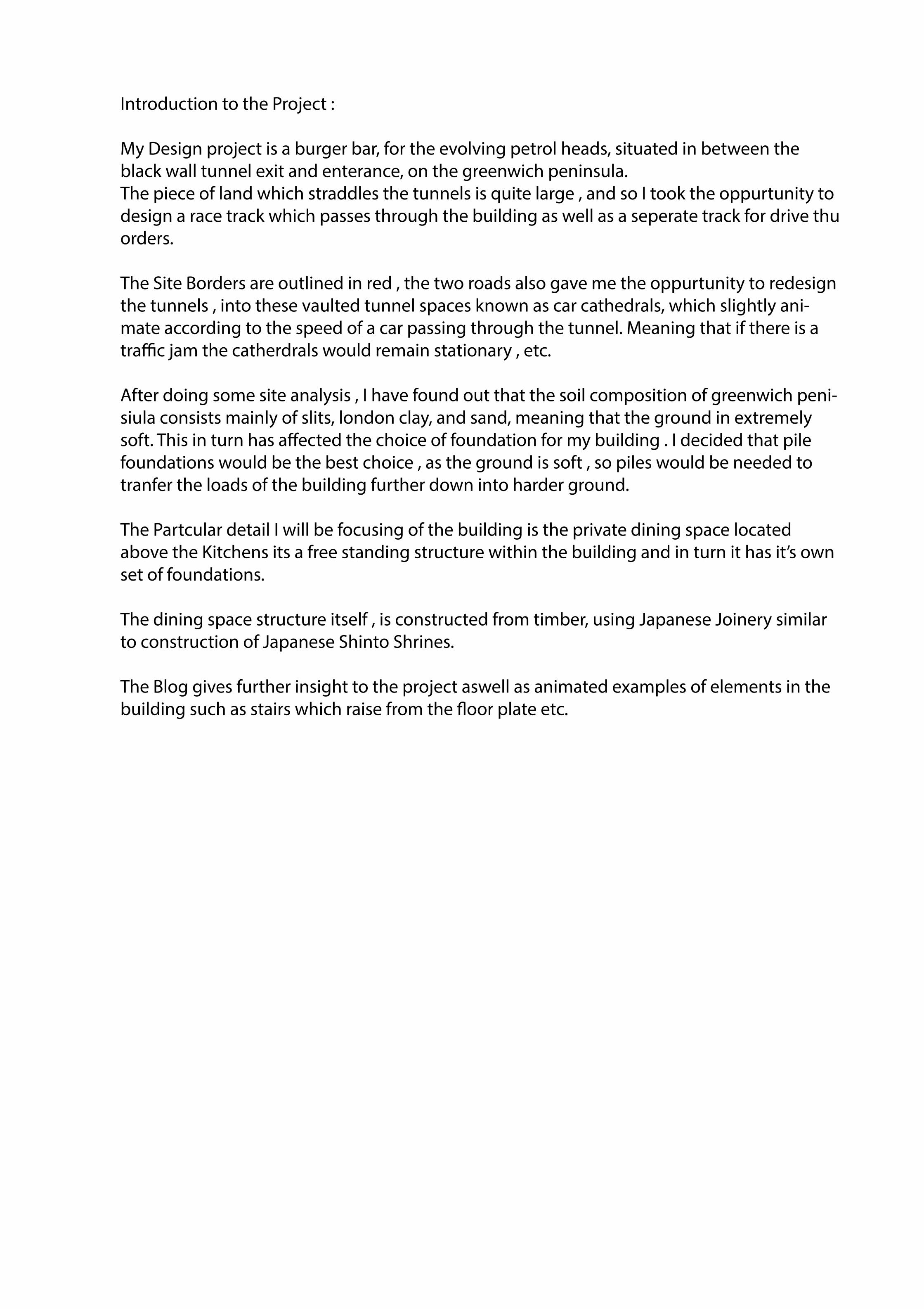
Introduction to the Project :
My Design project is a burger bar, for the evolving petrol heads, situated in between the black wall tunnel exit and enterance, on the greenwich peninsula.The piece of land which straddles the tunnels is quite large , and so I took the oppurtunity to design a race track which passes through the building as well as a seperate track for drive thu orders.
The Site Borders are outlined in red , the two roads also gave me the oppurtunity to redesign the tunnels , into these vaulted tunnel spaces known as car cathedrals, which slightly ani-mate according to the speed of a car passing through the tunnel. Meaning that if there is a tra�c jam the catherdrals would remain stationary , etc.
After doing some site analysis , I have found out that the soil composition of greenwich peni-siula consists mainly of slits, london clay, and sand, meaning that the ground in extremely soft. This in turn has a�ected the choice of foundation for my building . I decided that pile foundations would be the best choice , as the ground is soft , so piles would be needed to tranfer the loads of the building further down into harder ground.
The Partcular detail I will be focusing of the building is the private dining space located above the Kitchens its a free standing structure within the building and in turn it has it’s own set of foundations.
The dining space structure itself , is constructed from timber, using Japanese Joinery similar to construction of Japanese Shinto Shrines.
The Blog gives further insight to the project aswell as animated examples of elements in the building such as stairs which raise from the �oor plate etc.

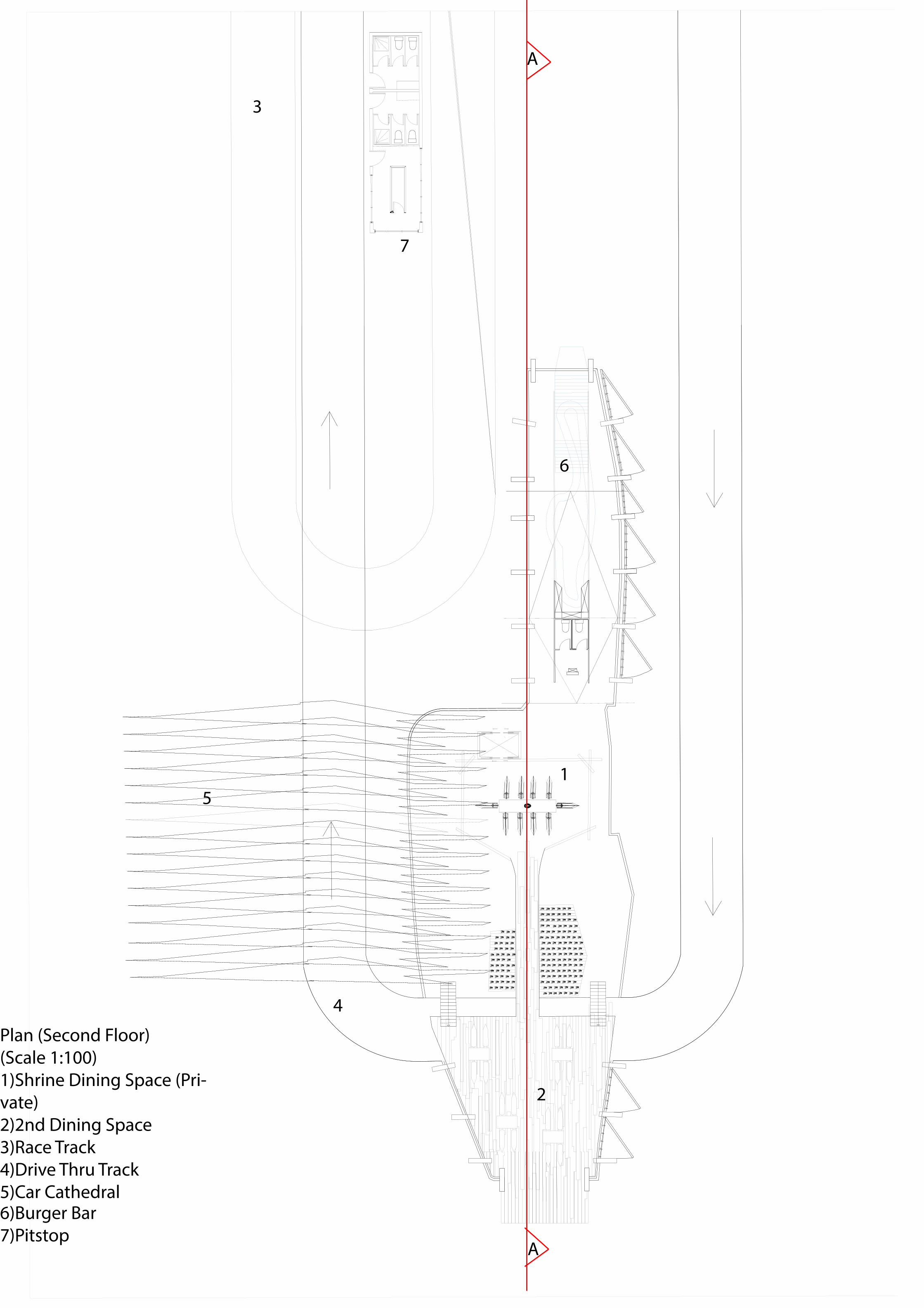
Plan (Second Floor) (Scale 1:100)1)Shrine Dining Space (Pri-vate)2)2nd Dining Space3)Race Track4)Drive Thru Track5)Car Cathedral6)Burger Bar7)Pitstop
1
2
3
4
5
6
7
A
A
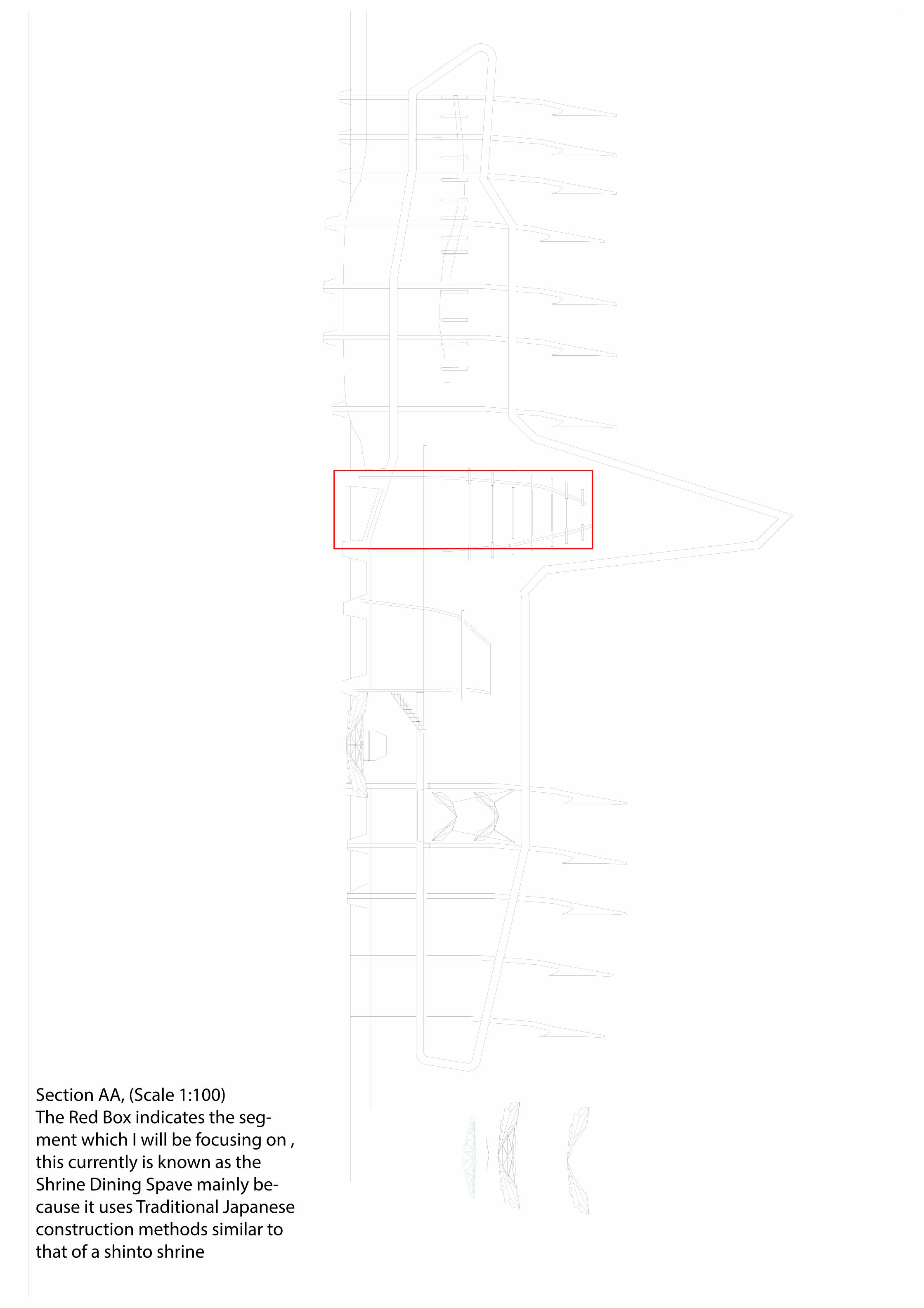
Section AA, (Scale 1:100)The Red Box indicates the seg-ment which I will be focusing on , this currently is known as the Shrine Dining Spave mainly be-cause it uses Traditional Japanese construction methods similar to that of a shinto shrine

Section through the shrine, showcasing the pile foundation as well as the hanging table and timbers.
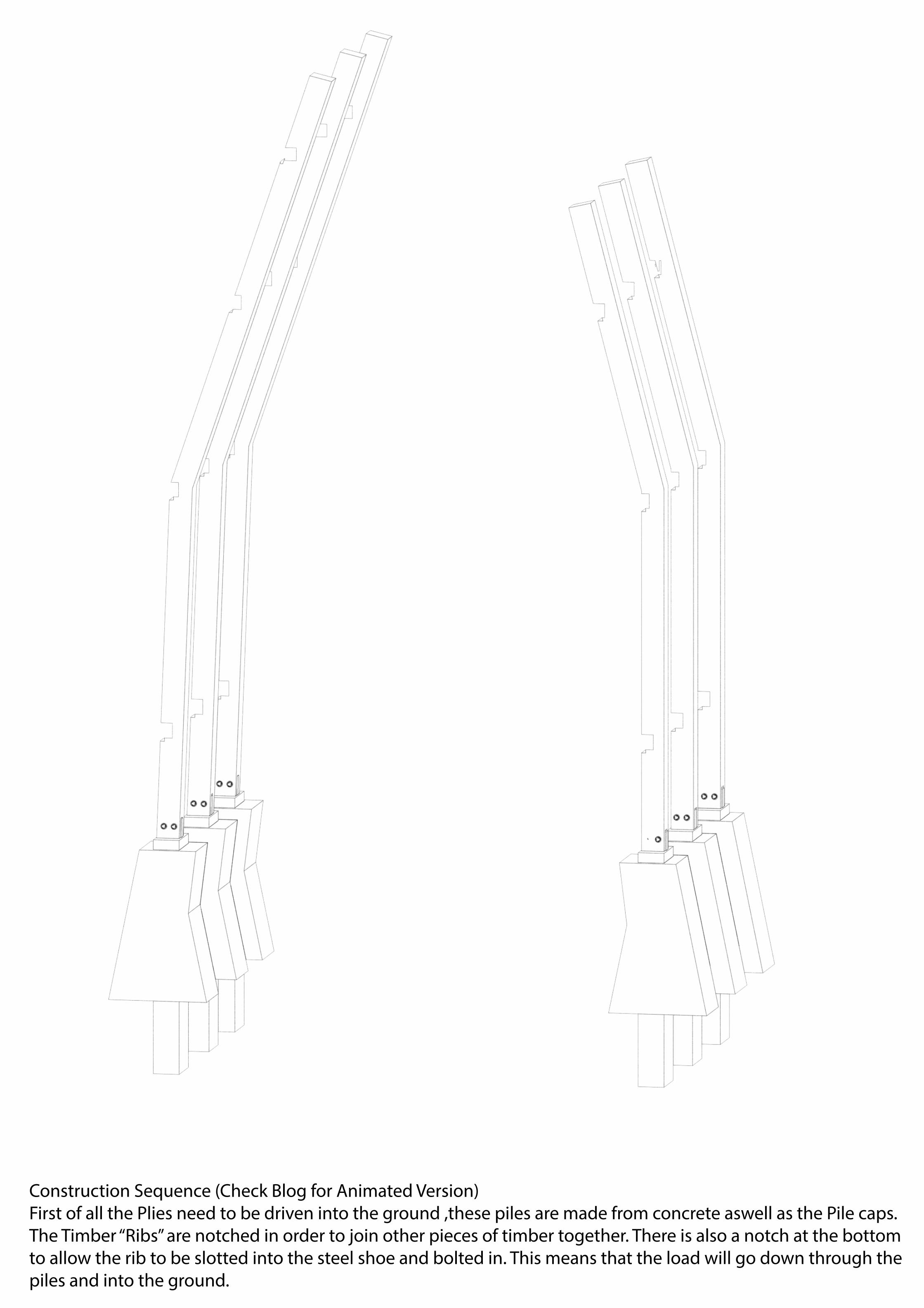
Construction Sequence (Check Blog for Animated Version)First of all the Plies need to be driven into the ground ,these piles are made from concrete aswell as the Pile caps.The Timber “Ribs” are notched in order to join other pieces of timber together. There is also a notch at the bottom to allow the rib to be slotted into the steel shoe and bolted in. This means that the load will go down through the piles and into the ground.
Plan (Second Floor) (Scale 1:100)1)Shrine Dining Space (Pri-vate)2)2nd Dining Space3)Race Track4)Drive Thru Track5)Car Cathedral6)Burger Bar7)Pitstop
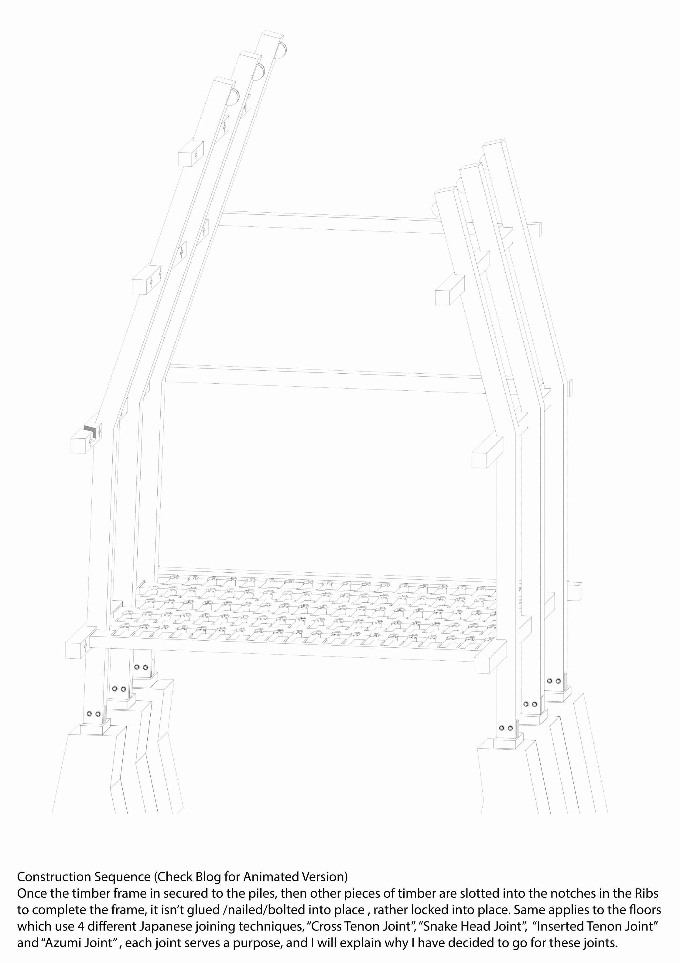
Construction Sequence (Check Blog for Animated Version)Once the timber frame in secured to the piles, then other pieces of timber are slotted into the notches in the Ribs to complete the frame, it isn’t glued /nailed/bolted into place , rather locked into place. Same applies to the �oors which use 4 di�erent Japanese joining techniques, “Cross Tenon Joint”, “Snake Head Joint”, “Inserted Tenon Joint” and “Azumi Joint” , each joint serves a purpose, and I will explain why I have decided to go for these joints.

Construction Sequence (Check Blog for Animated Version)This structure has no forms of insulation or under�oor heating considering that it is suspended above the kitch-ens which would circulate heated air above. Finally the cladding is attached to the frame, this is also supposed to be timber, which would be stapled/nailed to the frame. In addition to that a pully system is attached to the top of the frame, from which a cable net is suspended from, this in turn suspends the table in tension.

Exploded Axo of Shrine 1) Timber Structural Rib2) Pile (Concrete)3) Structural Concrete Pile Cap4) Steel Shoe5) Steel Bolts6) Cross Tenon Joint Male7) Cross Tenon Joint Female8) Snake Head Joint (within the horizon-tal �oor segments)9) Snake Head Joint Female (Within the vertical �oor segments)10) Inserted Tenon Joint (Beam)11) Azumi Jointed Timber12) Timber Cladding13) Pully System14) Tension Cable15) Cable Net16) C-Clamps17) Table
1)
2)
3)4)
5)
6)
7)
8)
9)
10)
11)
12)
13)
14)
14)
15)
16)17)
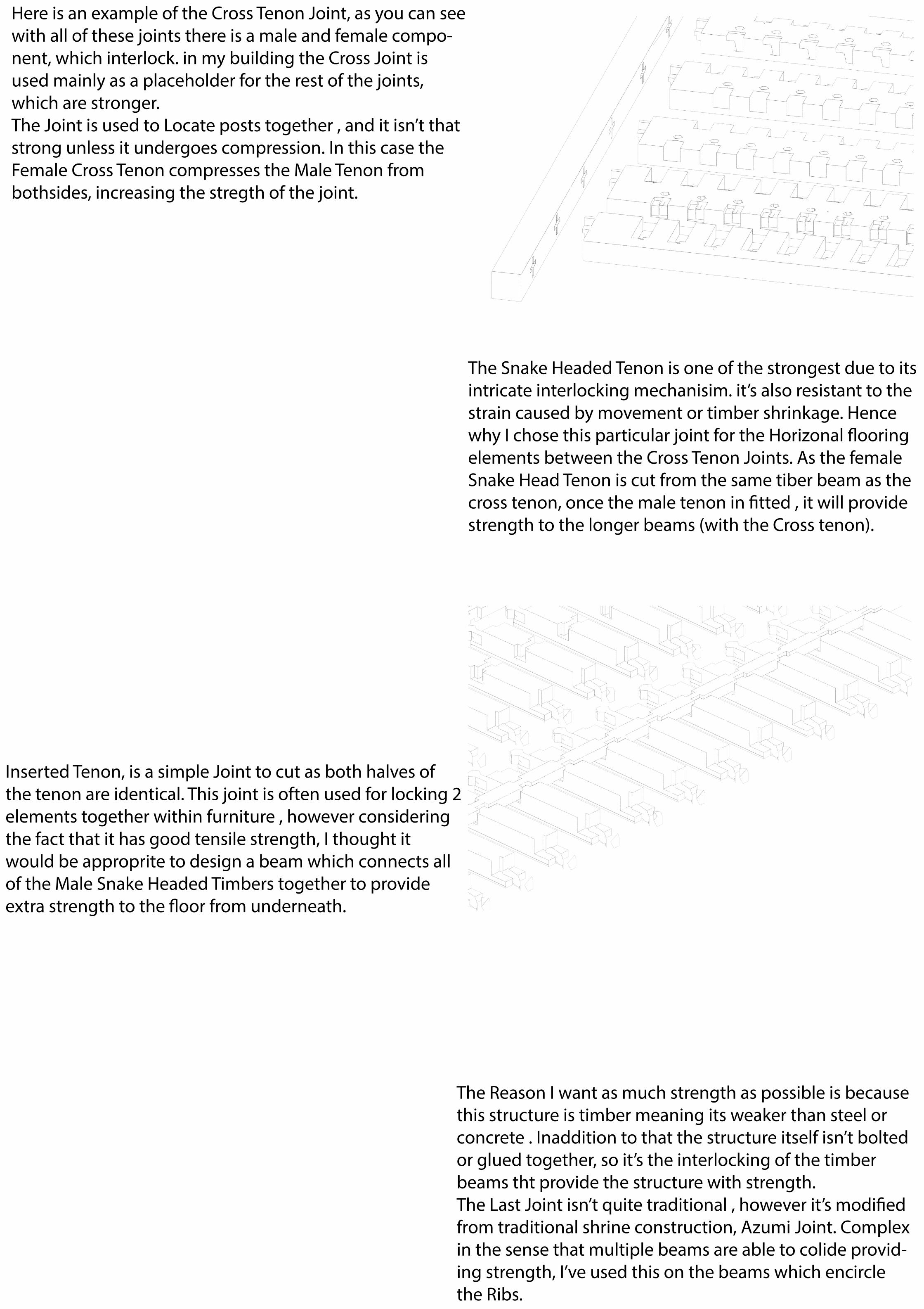
Here is an example of the Cross Tenon Joint, as you can see with all of these joints there is a male and female compo-nent, which interlock. in my building the Cross Joint is used mainly as a placeholder for the rest of the joints, which are stronger.The Joint is used to Locate posts together , and it isn’t that strong unless it undergoes compression. In this case the Female Cross Tenon compresses the Male Tenon from bothsides, increasing the stregth of the joint.
The Snake Headed Tenon is one of the strongest due to its intricate interlocking mechanisim. it’s also resistant to the strain caused by movement or timber shrinkage. Hence why I chose this particular joint for the Horizonal �ooring elements between the Cross Tenon Joints. As the female Snake Head Tenon is cut from the same tiber beam as the cross tenon, once the male tenon in �tted , it will provide strength to the longer beams (with the Cross tenon).
Inserted Tenon, is a simple Joint to cut as both halves of the tenon are identical. This joint is often used for locking 2 elements together within furniture , however considering the fact that it has good tensile strength, I thought it would be approprite to design a beam which connects all of the Male Snake Headed Timbers together to provide extra strength to the �oor from underneath.
The Reason I want as much strength as possible is because this structure is timber meaning its weaker than steel or concrete . Inaddition to that the structure itself isn’t bolted or glued together, so it’s the interlocking of the timber beams tht provide the structure with strength.The Last Joint isn’t quite traditional , however it’s modi�ed from traditional shrine construction, Azumi Joint. Complex in the sense that multiple beams are able to colide provid-ing strength, I’ve used this on the beams which encircle the Ribs.

Reference List :
Constructing Architecture (Pages 108-112, Fig 64, 65, 68)
Wood Joints in Classical Japanese Architecture (Torashichi Sumiyoshi & Gengo Matsui, 1989) (Pages 5, 17,66,67)
Tezuka Architects , Project : Woods of Net (http://www.tezuka-arch.com/japanese/works/for-est_of_net/01.html)
Note :Animations can be found on Tumblr Blog (Link is on the cover page) Along with these Drawings in higer resolution