Grease layer thickness measuring device SonicControl
36
INSTALLATION, OPERATION AND MAINTENANCE INSTRUCTIONS Grease layer thickness measuring device SonicControl Measurement, display and control of the depth of the grease layer Ultrasonic sensor for precision measurement accurate to centimetres Monitoring of wastewater temperature in the separator Protective rating ultrasonic probe IP 68 Battery back-up in the event of power failure Can be combined with all KESSEL grease separators Easy installation (inc. installation set) Product Advantages Company / Telephone No. Installation of this unit should be carried out by a licensed profes- sional servicer: Service Edition:: 08/2010 Number: 395-016EN Subject to technical amendments Picture shows No. 917821
Transcript of Grease layer thickness measuring device SonicControl

INSTALLATION, OPERATION AND MAINTENANCE INSTRUCTIONS
Grease layer thickness measuring device SonicControl
Measurement, display and control of the depth of the grease layer
Ultrasonic sensor for precision measurement accurate to centimetres
Monitoring of wastewater temperature in the separator
Protective rating ultrasonic probe IP 68
Battery back-up in the event of power failure
Can be combined with all KESSEL grease separators
Easy installation (inc. installation set)
Product Advantages
Company / Telephone No.
Installationof this unit should be carried out by a licensed profes-sional servicer:
Service
Edition:: 08/2010Number: 395-016ENSubject to technical amendments
Picture shows No. 917821

2
1. Safety Instructions .......................................................................................................... Page 42. General .......................................................................................................... Page 53. Installation and Assembly 3.1 Installation of the switch unit ................................................ Page 6
3.2 Installation of sensor and sensor bracket............................. Page 73.3 Installation dimensions of sensor ......................................... Page 83.4 Installation suggestion ......................................................... Page 10
4. Electrical connection 4.1 External signal generator ..................................................... Page 144.2 Shortening the control cable ................................................ Page 144.3 Potential-free switch contact ................................................ Page 144.4 Installation / cable connection.............................................. Page 154.5 Connection diagram............................................................. Page 18
5. Operation 5.1 .......Making the plant ready for operation.................................... Page 195.2 Duties of the user ................................................................. Page 195.3 Instruction / Handover.......................................................... Page 19
6. Treatment/Maintenance .......................................................................................................... Page 207. Errors and Malfunction 7.1 ......Incident display .................................................................... Page 21
7.2 ......Fault display......................................................................... Page 227.3 ......General faults....................................................................... Page 247.4 ......System faults ....................................................................... Page 25
8. Switch unit 8.1 ......Menu navigation................................................................... Page 268.2 ......System menu ....................................................................... Page 268.3 ......Information menu ................................................................. Page 278.3.1 ...Operating hours ................................................................... Page 278.3.2 ...Log book .............................................................................. Page 27
Contents

3
8.3.3 ...Control unit type................................................................... Page 278.3.4 ....Servicing date ...................................................................... Page 278.3.5 ...Current measured values..................................................... Page 278.3.6 ...Parametersr ......................................................................... Page 278.3.7 ....Measured data memory ....................................................... Page 278.3.8 ...Disposal ............................................................................... Page 278.4 ......Servicing menu .................................................................... Page 288.4.1 ....Manual mode ....................................................................... Page 288.4.2 ...Test mode ............................................................................ Page 288.4.3 ...Servicing dates .................................................................... Page 288.4.4 ....Disposal date ....................................................................... Page 288.5 ......Settings menu ...................................................................... Page 298.5.1 ...Parameters .......................................................................... Page 298.5.2 ....Profile memory..................................................................... Page 298.5.3 ...Date/time.............................................................................. Page 298.5.4 ....Type of system..................................................................... Page 298.5.5 ....Type of grease separator ..................................................... Page 298.5.6 ...Language............................................................................. Page 298.5.7 ...Communication .................................................................... Page 298.5.8 ....Sensors................................................................................ Page 298.5.9 ...Reset.................................................................................... Page 29
9. Technical data .......................................................................................................... Page 3010. Assessories .......................................................................................................... Page 3111. Declaration of Conformity .......................................................................................................... Page 3212. Guarantee .......................................................................................................... Page 3313. Handover Ceritficate .......................................................................................................... Page 34
Contents
4
1. Security Instructions
Dear customer,
Before you put your KESSEL SonicCon-trol into operation, please read throughthe installation instructions carefully andfollow them.
Check first whether the system has arrivedundamaged. In case of any transport dama-ge, please refer to the instructions in chap-ter 12 "Warranty".
1. Safety instructions:During installation, operation, maintenanceor repair of the system, the regulations forthe prevention of accidents, the pertinentDIN and VDE standards and directives, aswell as the directives of the local power sup-ply industry must be heeded.Before putting the device into operation,make sure through professional examinati-
on that the necessary protective features areavailable. Grounding, neutral, residual cur-rent-operated protective circuit etc. mustcorrespond to the requirements of the localpower supply industry.The system must not be operated in poten-tially explosive areas.The system contains electric charges. Non-compliance with the operating instructionsmay result in considerable damage to pro-perty, personal injuries or even fatal acci-dents.The system must be disconnected from themains before any work is carried out on it.It must be ensured that the electric cables aswell as all other electrical system equipmentare in a faultless condition. In case of da-mage, the system may on no account be putinto operation or must be stopped immedia-tely.
The regulations set out by the directive VDE0100 must beheeded. The switch unit must not be instal-led in rooms where there is an explosion ha-zard.The system must be inspected and servicedregularly to maintain its operational ability.We recommend that you conclude a servi-cing contract with your installation company.

5
Dear customer,
we are pleased that you have decided to buy a KESSEL product.The entire system was subjected to a stringent quality control before it left our factory. Nevertheless, please check immediately whetherthe system has been delivered to you complete and undamaged. In case of any transport damage, please refer to the instructions in thechapter “Warranty” in this manual.These installation, operating and maintenance instructions contain important information that has to be observed during assembly, ope-ration, maintenance and repair. Prior to carrying out any work on the system, the operator and the responsible technical personnel mustcarefully read and heed these installation and operating instructions.
2. General
Areas of application for the switch unit:The switch unit monitors the depth of the grease layer in KESSEL grease separators accurate to centimetres.

6
3. Installation and Assembly
3.1 Installation of the switch unit
The safety instructions in chapter 1 mustbe heeded!
The switch unit is installed in a suitable spot,e.g. at eye level on the wall. Screw in place(self-cutting screws) later using max. 1 Nm.Attach the switch box to the wall as shownusing the 4 wood screws M3.5x30. The woodscrews, plastic dowels and a drilling templa-te are included..
� Hinge (2x)� Plastic dowel (5x25 mm) (4x)� Slotted head wood screw M3.5x30 (4x) Cover screws max. 1 Nm (4x)
Note:See chapter 4.4 for cable lengths
Schematic diagram of the switch unit without electronic components

7
3. Installation and Assembly3.2 Installation of sensor and sensor bracket
� ��
� Place the drilling template on the outside of the outlet structure and drill 2 x Ø 4 mm holes(top two holes!).
� Place the drilling template on the inside of the outlet structure and fix in place from the outside (see ).� Put the upper and lower sections of the sensor bracket together and screw the pipe clamps
to the sensor bracket.� Screw the sensor bracket to the outlet structure using a torque of 1 Nm
and clip the sensor in place (see page 10).
� Upper section of sensorbracket
� Lower section of sensorbracket
� PT screw KB 60x30 PT screw Torx 40x12 PT screw Torx K 50x20� Pipe clamp PE d25� Sensor bracket Drilling
template/ screw cover Outlet structure partition� SonicControl sensor
�

3. Installation and Assembly3.3 Installation dimensions of sensor
Freie Aufstellung Artikel NS
Abstand Oberkannte unterer "Finger" zu Unterkannte Auslauf(Wasserlinie)
Bohrlöcher in Bohrschablone
Alarmniveau =max.Fettschicht-dicke in cm
empfohlenes Vor-alarmniveau in cm (= 2/3 des max. Speichervolumens)
EURO "G" obere beiden Bohrlöcher93002 2 50 cm obere beiden Bohrlöcher 23 1593004 4 50 cm obere beiden Bohrlöcher 24 1693007 7 50 cm obere beiden Bohrlöcher 27 1893010 10 50 cm obere beiden Bohrlöcher 24 16EURO "D"93002.00 / D1 2 50 cm obere beiden Bohrlöcher 23 1593004.00 / D1 4 50 cm obere beiden Bohrlöcher 24 1693007.00 / D1 7 50 cm obere beiden Bohrlöcher 27 1893010.00 / D1 10 50 cm obere beiden Bohrlöcher 24 16EURO "DS"93002.50 und .00 / DS1 2 50 cm obere beiden Bohrlöcher 23 1593004.50 und .00 / DS1 4 50 cm obere beiden Bohrlöcher 24 1693007.50 und .00/ DS1 7 50 cm obere beiden Bohrlöcher 27 1893010.50 und .00 / DS1 10 50 cm obere beiden Bohrlöcher 24 16EURO E+S "M"93002.50 und .00 / M1 2 50 cm obere beiden Bohrlöcher 23 1593004.50 und .00 / M1 4 50 cm obere beiden Bohrlöcher 24 1693007.50 und .00 / M1 7 50 cm obere beiden Bohrlöcher 27 1893010.50 und .00 / M1 10 50 cm obere beiden Bohrlöcher 24 16EURO E+S "PV"93002.50 und .00 / P1 2 50 cm obere beiden Bohrlöcher 23 1593004.50 und .00 / P1 4 50 cm obere beiden Bohrlöcher 24 1693007.50 und .00 / P1 7 50 cm obere beiden Bohrlöcher 27 1893010.50 und .00 / P1 10 50 cm obere beiden Bohrlöcher 24 16DIN 4040 "G" rund98201 1 58 cm obere beiden Bohrlöcher 16 1198202 2 58 cm obere beiden Bohrlöcher 16 11DIN 4040 "D" rund98201.00/D1 1 58 cm obere beiden Bohrlöcher 16 1198202.00/D1 2 58 cm obere beiden Bohrlöcher 16 11
E
8
free standing Article No. NS
Distance between theupper edge of thelower “finger” and thelower edge of the outlet(water line)
Drill holes indrilling template
Alarm level= max. greaselayer thicknessin cm
Recommended prelimi-nary alarm level in cm(= 2/3 of the max. stora-ge volume)
Top two drill holesTop two drill holesTop two drill holesTop two drill holes
Top two drill holesTop two drill holesTop two drill holesTop two drill holesTop two drill holesTop two drill holesTop two drill holesTop two drill holes
Top two drill holesTop two drill holesTop two drill holesTop two drill holes
Top two drill holesTop two drill holesTop two drill holesTop two drill holesTop two drill holesTop two drill holes
Top two drill holesTop two drill holes
max. sludge layerin cm ( = 50% ofsludgetrap volume)
20253027
20253027
20253027
20253027
20253027
4654
1423

9
3. Installation and Assembly
Installation dimensions of sensor
Note: After installation, fill the grease separator completely with water, check the installation height and correct if necessary!If mechanical correction is not possible, carry out change in “Parameters” (chapter 8.5.1).The parameters are password-protected – please contact KESSEL Customer Services. (Phone +49 (0) 8456/27462).
93001 / 80 / 120 B und D 1 50 cm obere beiden Bohrlöcher 17 1193002 / 80 / 120 B und D 2 50 cm obere beiden Bohrlöcher 17 1193004 / 80 / 120 B und D 4 50 cm obere beiden Bohrlöcher 17 1193007 / 120 B und D 7 48 cm untere beiden Bohrlöcher 17 1193010 / 120 B und D 10 48 cm untere beiden Bohrlöcher 17 1193015 / 120 B und D 15 56 cm untere beiden Bohrlöcher 17 1193020 / 120 B und D 20 56 cm untere beiden Bohrlöcher 17 11DIN 4040 "G"98201 / 00 / 80 / 120 B und D 1 58 cm untere beiden Bohrlöcher 16 1198202 / 00 / 80 / 120 B und D 2 58 cm untere beiden Bohrlöcher 16 1198204 / 00 / 80 / 120 B und D 4 58 cm untere beiden Bohrlöcher 16 11
Für weitere Artikel kontaktieren Sie bitte den KESSEL-Werkskundendienst (Telefon +49 (0) 8456 / 27462)
Top two drill holesTop two drill holesTop two drill holesBottom two drill holesBottom two drill holesBottom two drill holesBottom two drill holes
Bottom two drill holesBottom two drill holesBottom two drill holes
Article No. NS
Distance between theupper edge of thelower “finger” and thelower edge of the outlet(water line)
Drill holes indrilling template
Alarm level= max. greaselayer thicknessin cm
Recommendedpreliminaryalarm level in cm(= 2/3 of the max.storage volume)
UndergroundInstalltaion
For further articles, please contact KESSEL Customer Services (Phone +49 (0) 8456 / 27462)
max. sludge layerin cm ( = 50% ofsludgetrap volume)
11152723233231
465454

10
3. Installation and Assembly
Grease separator < NS 15
Tank wall < = 10 mm
3.4 Installation suggestion
Sensor cable
Cable screw connection*
Grease separator > NS 15
Tank wall > = 10 mm
Thread PG 11
Cable screw connection*
Drill hole ø 19 mm
* To avoid odour pollution, fasten the cablescrew connection tightly.Illustration shows free-standing grease separator Euro NS 2

11
The sensor must be attached (approx. 60° angle)in such a way that there is no strutting between thetwo “fingers”
3. Installation and Assembly
Do not lay thecable undertension.
12
3. Installation and Assembly
Illustration shows grease separator forunderground installation NS 7-20
Illustration shows grease separator for underground installationNS 1-4
During ground-moving work, a PE-HD cable conduit DN 40 (outer dia. 50 mm) must belaid. For this purpose, the tank must be scored using a 60 mm saw cap. The connectiondistance between separator and switch unit must be kept as short as possible. Unneces-sary changes of direction, particularly ones at angles greater than 45° must be avoided.The cable conduit must have a continuous gradient to the separator. Condensation insi-de the cable conduit can be minimised through an airtight seal on the conduit on the switchunit side. A cable pull wire can be included for any later cable installation. The cable canbe extended to a max. 30 m. When the cable is drawn into the conduit to the switch unit,the cable screw connection at the conduit cover must be tightened firmly.Then the union nut must be fixed on the end of the pipe.
Inside Outside
Art. -Nr. 917822

13
3. Installation and Assembly
The enclosed sticker serves as a reminder for the disposer, in order to avoid da-mage to the sensor during disposal.
The sticker must be attached as follows:
Free-standing grease separatorAt eye level on the outside of the tank
Grease separator for underground installationOn the inside of the attachment piece
Note: Draw the respective disposersʼ attention to the sensor!
14
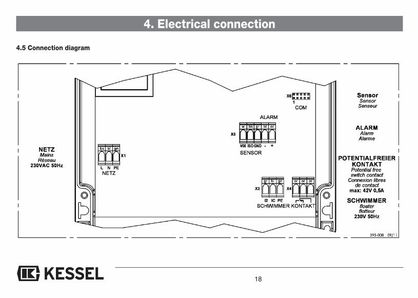
4. Electrical connection
4.1 1 External signal generatorThe external signal generator (order no. 20162) for transmitting theacoustic warning to other rooms can be connected if required.
4.2 Shortening the sensor cablesThe sensor cables can be shortened if required. We only recom-mend subsequently tin-plating the wire ends. When cable end slee-ves are used, care must be taken that the connection terminals aredesigned for a max. cross-section of 2.5 mm2. This cross-sectionmust not be exceeded.
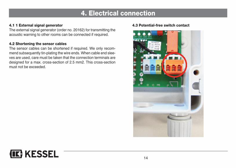
4.3 Potential-free switch contact

15
4. Electrical connection4.4 Installation / cable connectionThe connection cables must be connectedexactly according to the connection dia-gram. To do this, first pierce the cable screwconnections using a screwdriver (fig. a), in-sert the cable (fig. b) and connect up (fig. c).Then the nut on the cable screw connectioncan be tightened by hand (fig. d).The technical data must be heeded duringconnection of the potential-free switchcontact.The seals on the cable screw connec-tions that are not used, i.e. that no cablesare routed through, must not be pierced.They are used to seal the housing.
Important: All the cables connected to the electrical switch unit must be fixed in placeusing suitable measures (e.g. cable ties) so that they do not cause a hazard in the 1-errorcase, i.e. if a connection becomes loose.The sensor cable must be routed separately from the mains cable to avoid perturbation.

16
4. Electrical connection
Possibilities of professional cableextension on site (IP 68)The SonicControl cable is ten metres long.On site, this cable can be extended by aqualified electrician up to max. 30 metreswithout any change in cross-section beingnecessary. If the cable is extended to morethan 30 metres, proper function can no lon-ger be guaranteed since the induction forceswhich occur can lead to interference.
SonicControl probe extension to max. 30metres 0,75 mm2
Note:The regulations set out by the directiveVDE 0100 must be heeded. The switchunit must not be installed in potentiallyexplosive areas. The 510 m cable canbe extended on site to up to 30 m. If thecable is routed in a cable channel withcables from other frequency-controlledunits, a shielded cable has to be used!
Fig. 1: Crimp cable extension with butt jointFig. 2: Shell is placed around the cable, both shell ends are sealedFig. 3: Cast the shell with prepared casting resinFig. 4: Final state with sealing plug
Individual parts on request
Fig.1
Fig.2
Fig.3
Fig.4
17
4. Electrical connection
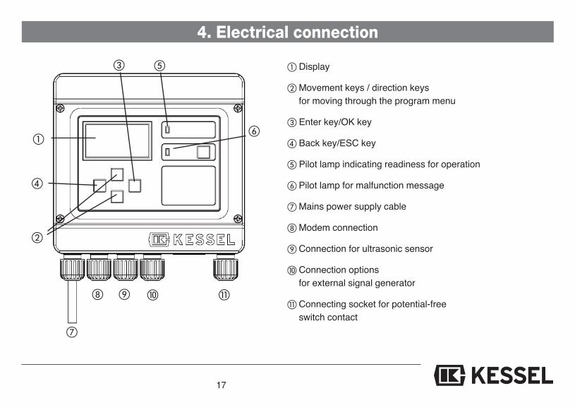
� Display
� Movement keys / direction keysfor moving through the program menu
� Enter key/OK key
Back key/ESC key
Pilot lamp indicating readiness for operation
� Pilot lamp for malfunction message
� Mains power supply cable
Modem connection
� Connection for ultrasonic sensor
� Connection optionsfor external signal generator
� Connecting socket for potential-freeswitch contact
�
�
�
�
�
� ��
18
4. Electrical connection
4.5 Connection diagram

19
5. Operation
5.1 Getting the system ready for opera-tion
Plug the mains plug of the control unit intothe socket. The system will initialise auto-matically. During initial initialisation of thesystem, the control unit requests four basicsettings.1. Language2. Date/time3. Type of system*4. Type of grease separator*
➤ Selection using ��
➤ Stored in system memory by pressing“OK”
➤ After setting 1 to 4.➤ Switch unit loads program memory➤ Start operating mode➤ System is ready for operation
* see page 29
5.2 Operator's dutiesChecking- for transport or installation damage- for structural defects of all electricaland mechanical components for seat andfunction
- the cable connections
Customer instruction based on the in-stallation and operating instructions- Go through installation and operating in-structions with the customer
- System operation (explaining anddescribing)
- Explanation to the customer about theoperator’s duties
- Remind about regular servicing (seechapter 6)
5.3 Instruction / handover
The chapter "Safety instructions" mustbe heeded (page 4)!Commissioning is carried out by a speciali-sed firm or by an authorised KESSEL agent(at an additional charge). The following per-sons should be present for the handover:- Person authorised to perform the accep-tance on behalf of the building owner
- Specialised firm
In addition, we recommend the participationof operating personnel/operator and thewaste disposal contractor.Summary of instruction:- Get the system ready for operation- Check the system- Instruction based on the installation andoperating instructions
- Preparation of the handover certificate(see chapter 13)
➤ Once instruction is completed, the sy-stem must be made ready for operation.
�Correct enternecessary formeasuring
20
6. Inspection and Maintenance
Please heed the safety instructions in chapter 1.The switch unit must be completely disconnected from the mainsfor cleaning. When replacing the batteries, use Mignon AA 1200mAh. Repairs may only be carried out by the manufacturer.The switch unit does not require any maintenance.The connection cables must be checked for damage. If any dama-ge can be detected, the system must be put out of operation im-mediately.The sensor has to be cleaned at regular intervals.
Every time disposal takes place the sensor must be cleaned withwarm/hot water*. When a high-pressure jet cleaner is used, main-tain a safe distance of 30 cm.The sensor does not have to be removed for cleaning.
* In the case of KESSEL M and PV grease separator systems, clea-ning can wait until the next servicing date since the separator isautomatically cleaned with warm water. If necessary (heavy sen-sor soiling) carry out cleaning every time disposal is carried out.

21
7. Errors and MalfunctionPlease heed the safety instructions in chapter 1.7.1 Incident display (only in the log book):
Incident display Cause RemedyFirst initialisation First initialisation - -Parameters changed Parameters have been changed - -Type of system changed Type of system has been changed - -Servicing Servicing date has been entered - -Manual mode Manual mode has been entered - -Readout log book Log book has been read out - -Close down switch unit Switch unit has been closed down - -Acknowledge acoustic alarm Acoustic alarm has been acknowledged - -Acknowledge fault Fault has been acknowledged - -Default settings Reset to default settings - -Sensor entry 01 Problem with the sensor system Contact Customer ServicesSensor entry 02 Problem with the sensor system Contact Customer ServicesSensor entry 03 Problem with the sensor system Contact Customer ServicesSensor entry 04 Problem with the sensor system Contact Customer ServicesSensor entry 05 Problem with the sensor system Contact Customer ServicesSensoreintrag 06 Problem with the sensor system Contact Customer Services
KESSEL Customer Services Tel. +49 (0)8456/27462

22
7. Errors and Malfunction
Incident display Fault Cause RemedyPRE-ALARM layer thickness Flashing (alarm) Depth of grease layer for Heed depth of grease height
Pre-alarm level and inform the disposerhas been reached (see 3.3) if appropriate
No rest phase detected Flashing (alarm) Measurement takes place Check measuring range in theduring operating phases Parameters menu item and set(inaccuracies possible) again if necessary
ALARM layer thickness Acoustic signal and flashing Maximum grease layer Inform the disposerthickness has been reached
ALARM temperature Acoustic signal and flashing Inlet temperature too high Reduce temperature of(heed standard requirements inlet waterwhen setting the level)
Battery voltage too high Acoustic signal and flashing Battery contact error Check battery polarity and seat
Battery voltage too low Acoustic signal and flashing Battery defective or service Replace the batterylife exceeded
Mains failure Acoustic signal and flashing ; - The system is currentless - Check pre-fuse and / or RCDPower LED is flashing - The display is defective
- Call Customer Services
7.2 Fehleranzeige:

23
7. Errors and Malfunction
Incident display Fault Cause RemedyCommunication error Acoustic signal and flashing Faulty modem reception Step 1: Check basic reception
possibility;
Step 2: If no reception is possiblethen a modem cannot be used;if reception is basically possible,replace the modem
Sensor fault 01 Acoustic signal and flashing Problem with the sensor system Contact Customer ServicesSensor fault 02 Acoustic signal and flashing Problem with the sensor system Contact Customer ServicesSensor fault 03 Acoustic signal and flashing Problem with the sensor system Contact Customer ServicesSensor fault 04 Acoustic signal and flashing Problem with the sensor system Contact Customer ServicesSensor fault 05 Acoustic signal and flashing Problem with the sensor system Contact Customer ServicesSensor fault 06 Acoustic signal and flashing Problem with the sensor system Contact Customer ServicesSensor faul t07 Acoustic signal and flashing Problem with the sensor system Contact Customer ServicesSensor fault 08 Acoustic signal and flashing Problem with the sensor system Contact Customer Services
KESSEL Customer Services Tel. +49 (0)8456/27462

24
7. Errors and Malfunction
7.3 General faults::Recognised fault Fault Cause RemedyDeviation between the Faulty function caused by - Faulty sensor installation - Tighten the cable a little andgrease layer depth in the faulty measurement then tighten the screwinspection window and the connection by handmeasured depth of grease - Positioning during - Take the type of separatorlayer installation into account
- Faulty initial initialisation - Re-calibration of the sensor- Dirt deposited on the sensor - Check the position of the
sensor- Set the type of grease- Set the type of greaseClean the sensor
- Sensor is in the blind spot - Reposition the sensor(see Page 11)
- Grease separator type / - Correct settingsand/or system type not setcorrectly
Text message cannot be Faulty function of remote Faulty modem reception Step 1: Check basic receptionsent and/or remote servicing servicing possibility;is not possible Step 2: If no reception is
possible, then a modemcannot be used; if reception isbasically possible, replace themodem
25
7. Errors and Malfunction7.4 System faultsRecognised fault Cause RemedyOdour pollution Leak in the cable duct through Tighten the cable screw connection in
faulty installation the tank wall so that it is odour-proof(see the operating instructions of yourgrease separator as well)
Water in the service room Leak in the cable duct through Tighten the cable screw connection infaulty installation the tank wall so that it is “odour”-proof

26
8. Switch unit
8.1 Menu guidanceThe control unit's menu navigation is sub-divided into the system information as wellas three different main menu items. Thebackground lighting is activated if one ofthe control keys is pressed once.
OK key Skip to the next higher levelESC key : Skip to the next lower level� Navigation within a level�
The acoustic signal can beacknowledged by pressingthis key once..If the fault has been elimi-nated, the visual fault canalso be acknowledged bypressing the alarm keyonce more.
If the fault has not been eliminated, theacoustic alarm is triggered again whenthe alarm key is pressed again.
In case of a mains power failure, the sy-stem is not ready for operation. The con-trol unit switches to stand-by mode (bat-tery operation). This becomes noticeableby means of an acoustic and visual alarm.The acoustic alarm can be acknowledgedby pressing the alarm key. Stand-by modeis maintained for at least 72 hours. After-wards, the control unit switches off auto-matically. If the mains connection is re-established within one hour, the programwill automatically continue with the lastprogram phase. If this is not the case, thedevice re-initialises itself when the mainsconnection returns (programming alreadycarried out remains). This can also be car-ried out manually by prolonged pressingof the alarm key.
Note:Certain menus are password-protected.This serves to protect the system againstinappropriate use.If you have any questions, please contactKESSEL Customer Services (Phone +49(0) 8456 / 27462)
Alarm key 8.2 System menu
Systeminfo Information
Servicing
Settings

27
8. Switch unit
8.3.1 Operating hoursDisplay of all system operating times.8.3.2 Log bookChronological display of incidents and faults (see also chapter 7 “Incidents andfaults / remedial measures”)All changes made to the settings are saved at this point.8.3.3 Control unit typeDisplay of system time, grease separator type, language and software status.8.3.3 Servicing dateDisplay of the next necessary and last performed servicing.Note: Data are only available if these have been stored in the “Settings” menu bythe servicing partner.8.3.5 Current measured valuesPressing the OK key carries out a measurement of the current grease layer thickn-ess.8.3.6 ParametersDisplay of all set control parameters of the system It is not possible to change theparameters in this menu.8.3.7 Measured data memoryDisplay of the last layer thickness and temperature stored (max. 400 values).8.3.8 DisposalDisplay of details of the last disposal carried out (if stored)
8.3 Information menu
Systeminfo Information
Servicing
Settings
Operating hours
Log book
Control unit type
Servicing date
Currentmeasured values
Parameters
Measured data-memory
Disposal

28
8.4 Servicing menu
8. Switch unit
8.4.1 Manual modeManual operation overrides automatic operation.8.4.2 Automatic test mode8.4.3 Servicing dateEntry of the last servicing to be carried out and the next servicing date by theservicing partner.8.4.4 Disposal dateEntry of the last disposal carried out (e.g. by the disposal partner)
Systeminfo Information
Servicing
Settings
Manual mode
Test mode
Servicing date
Disposal date

29
8. Switch unit
8.5.1 ParametersChanges to default parameter settings (refer also to 3.3)Note: Every change is immediately accepted when the OK key is pressed. In ad-dition, on quitting this menu it is possible to save these values in the profile me-mory under a separate name.8.5.2 Profile memoryLoading of the values accepted on initialisation and of the values added under anew name (see 8.5.1).8.5.3 Date/time Setting the current date and time.8.5.4 Type of systemSelection of the average grease content occurring and type of grease.8.5.5 Type of grease separator Selection of the type of grease separator.8.5.6 Language Display / change the language.8.5.7 CommunicationInput / change of the station name, the device number, the modem type, the PINSand the number of the mobile phone to which possible malfunctions can be sentby text message (for a detailed description see separate operating instructions).8.5.8 Sensors Sensor address assignment.8.5.9 ResetReset the switch unit to the default setting (operating hours are not reset).
8.5 Settings menuSysteminfo Information
Servicing
Settings Parameters
Profile memory
Date / time
Type of System
Type ofgrease separator
Language
Communication
Sensors
Reset
30
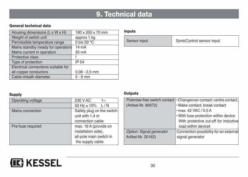
9. Technical dataGeneral technical data
Housing dimensions (L x W x H) 180 x 200 x 70 mmWeight of switch unit approx 1 kgPermissible temperature range 0 bis 50 °CMains standby (ready for operation) 14 mAMains current in operation 35 mAProtective class IType of protection IP 54Electrical connections suitable forall copper conductors 0,08 - 2,5 mmCable sheath diameter 5 - 9 mm
SupplyOperating voltage 230 V AC 1~
50 Hz ± 10% L / NMains connection Safety plug on the switch
unit with 1.4 mconnection cable
Pre-fuse required max. 16 A (provide oninstallation side),all-pole main switch inthe supply cable
Inputs
Sensor input SonicControl sensor input
Outputs
Potential-free switch contact • Changeover contact: centre contact,(Artikel-Nr. 80072) • Make contact; break contact
• max. 42 VAC / 0.5 A• With fuse protection within device• With protective cut-off for inductive
load within devicetOption: Signal generator Connection possibility for an externalArtikel-Nr. 20162) signal generator

31
10. Accessories
Order-Nr.11. Control unit 395-00512. Ultrasonic sensor 395-0043. Duct set for installation in the ground 9178221
�
inside outside

32
EC DECLARATION OF CONFORMITYAccording to the Low Voltage Guidelines 2006/95/EG, Electromagnetism Guidelines 2004/108/EG
KESSEL AG, Bahnhofstraße 31, D-85101 LentingHerewith we declare, that the product
KESSEL- SonicControl917821
is in agreement with
EN 60204-1 (2006), EN 61000-6-1 (2007), EN 61000-6-2 (2006), EN 61000-6-3 (2007), EN 61000-6-4 (2007)
Lenting, 8.12.2009
Managing Board Managing Board
33
12. Guarantee
1. In the case that a KESSEL product is defective, KESSEL has the op-tion of repairing or replacing the product. If the product remains de-fective after the second attempt to repair or replace the product or itis economically unfeasible to repair or replace the product, the cu-stomer has the right to cancel the order / contract or reduce paymentaccordingly. KESSEL must be notified immediately in writing of de-fects in a product. In the case that the defect is not visible or difficultto detect, KESSEL must be notified immediately in writing of the de-fect as soon as it is discovered. If the product is repaired or replaced,the newly repaired or replaced product shall receive a new warrantyidentical to that which the original (defective) product was granted.The term defective product refers only to the product or part needingrepair or replacement and not necessarily to the entire product orunit. KESSEL products are warranted for a period of 24 month. Thiswarranty period begins on the day the product is shipped form KES-SEL to its customer. The warranty only applies to newly manufactu-red products. Additional information can be found in section 377 ofthe HGB.
In addition to the standard warranty, KESSEL offers an additional 20year warranty on the polymer bodies of class I / II fuel separators,grease separators, inspection chambers, wastewater treatment sy-stems and rainwater storage tanks. This additional warranty appliesto the watertightness, usability and structural soundness of the pro-duct.A requirement of this additional warranty is that the product is pro-perly installed and operated in accordance with the valid installationand user's manual as well as the corresponding norms / regulations.
2. Wear and tear on a product will not be considered a defect. Problemswith products resulting from improper installation, handling or main-tenance will also be considered a defect.
Note:Only the manufacturer may open sealed components or screwconnections. Otherwise, the warranty may become null and void
01.06.2010

34
13. Handover certificate
Type description *KESSEL order number *Date of manufacture *(* according to type plate/invoice)Object description / system operatorPlannerAdress / TelephonePlannerAdress / TelephoneInstallation company involvedAdress / TelephonePerson authorised to perform the acceptanceAdress / TelephonePerson responsible for handoverOther remarksThe initial installation and instruction listed was carried out in the presence of the person authorised to perform the acceptance and thesystem operator.______________________________ ______________________________ _________________________Place, date Signature of authorised person Signature of system operator

13. Handover Certificate�
��
��
��
35
Dem Auftraggeber/Inbetriebnehmer wurden folgende Bauteile und/oder Produktkomponenten übergeben**:

Solutions from a single sourceE v e r y t h i n g f o r D r a i n a g eBackwater valves and cleanouts
Volatile liquid traps
Lifting stations, pumps, warningand control units
Rainwater management systems
Grease, starch and oil / fuelseparators
Inspection chambers
Custom projects for industrialapplications
Polymer pipe fittings
Stainless steel drains andchannels