(GRE) Glassfiber Reinforced Epoxy 2416
28
© Ameron 2008. FP 966 03/08. Page 1 of 28. Printed in The Netherlands. Bondstrand 2416 / 3416 Glassfiber Reinforced Epoxy (GRE) Pipe Systems for Industrial and Oilfield services for 16 bar pressure Laminate meets requirements of API Specification 15LR and ASME B31.3. Standard pipe wall design using a static hydrostatic design basis (ASTM D2992 procedure B) with a 0.5 service factor. This pipe system has a 4:1 safety factor in accordance with ASTM-D-1599. Maximum operating temperature: up to 121°C; Pipe diameter: 2-40 inch (50-1000 mm); Pipe system design for pressure ratings up to 16 bar; The pipe system is also available in other pressure classes (10 bar, up to 50 bar, higher pressure classes on request) ASTM D-2992 Hydrostatic Design Basis (Procedure B -service factor 0.5); ASTM D-1599 Safety factor of 4:1. Bondstrand 2400 / 3400 ASTM D-2310 Classification: RTRP-11FX for static hydrostatic design basis. Applications Performance Characteristics ● Brackish water lines ● Drain lines ● Cooling water lines ● Electrical conduit ● Crude oil transmission lines ● Firewater lines ● General industrial service for ● Temporary pipelines mildly corrosive liquids ● Oil field reinjection lines ● Potable water lines ● Saltwater and seawater lines ● Waste water and sewage lines Key-Lock® joint Taper/Taper joint
-
Upload
carlos-yanez -
Category
Documents
-
view
893 -
download
61
description
Piping Materials
Transcript of (GRE) Glassfiber Reinforced Epoxy 2416
© Ameron 2008. FP 966 03/08. Page 1 of 28. Printed in The Netherlands.
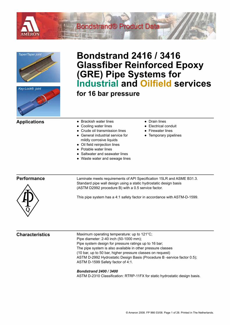
Bondstrand 2416 / 3416 Glassfiber Reinforced Epoxy (GRE) Pipe Systems for Industrial and Oilfield services for 16 bar pressure
Laminate meets requirements of API Specification 15LR and ASME B31.3. Standard pipe wall design using a static hydrostatic design basis (ASTM D2992 procedure B) with a 0.5 service factor.
This pipe system has a 4:1 safety factor in accordance with ASTM-D-1599.
Maximum operating temperature: up to 121°C;Pipe diameter: 2-40 inch (50-1000 mm);Pipe system design for pressure ratings up to 16 bar;The pipe system is also available in other pressure classes (10 bar, up to 50 bar, higher pressure classes on request)ASTM D-2992 Hydrostatic Design Basis (Procedure B -service factor 0.5);ASTM D-1599 Safety factor of 4:1.
Bondstrand 2400 / 3400ASTM D-2310 Classification: RTRP-11FX for static hydrostatic design basis.
Applications
Performance
Characteristics
● Brackish water lines ● Drain lines● Cooling water lines ● Electrical conduit● Crude oil transmission lines ● Firewater lines● General industrial service for ● Temporary pipelines mildly corrosive liquids● Oil field reinjection lines● Potable water lines● Saltwater and seawater lines ● Waste water and sewage lines
Key-Lock® joint
Taper/Taper joint
© Ameron 2008. FP 966 03/08. Page 2 of 28. Printed in The Netherlands.
Table of Contents GENERAL DATA
Adhesive ............................................................................................................. 20
Bending radius (minimal allowable) ...................................................................... 7
Conversions........................................................................................................ 27
Engineering design & installation data ............................................................... 27
Field testing ........................................................................................................ 27
Important notice .................................................................................................. 27
Joining system and configuration ......................................................................... 3
Typical mechanical properties .............................................................................. 4
Typical physical properties ................................................................................... 4
Pipe series ............................................................................................................ 3
Typical pipe length ................................................................................................ 4
Typical pipe dimensions and weights ................................................................... 6
Typical pipe performance ..................................................................................... 5
Span length (for horizontal support) ..................................................................... 7
Surge pressure ................................................................................................... 27
TAPER/TAPER FITTINGS DATA
Couplings............................................................................................................ 18
Elbows .............................................................................................................. 8-9
Flanges .....................................................................................................16-17-18
Taper/Taper dimensions ....................................................................................... 8
Nipples................................................................................................................ 19
Reducers ....................................................................................................... 14-15
Saddles.................................................................................................... 12-13, 19
Specials .............................................................................................................. 27
Stub-ends ........................................................................................................... 17
Tees .......................................................................................................... 10-11-12
KEY-LOCK FITTINGS DATA
Adapter .............................................................................................................. 26
Couplings ........................................................................................................... 24
Elbows .......................................................................................................... 21-22
Flanges ............................................................................................................... 24
Key-Lock dimensions ......................................................................................... 21
Nipples................................................................................................................ 25
Tees ............................................................................................................... 22-23

© Ameron 2008. FP 966 03/08. Page 3 of 28. Printed in The Netherlands.
Pipe series PipeFilament-wound Glassfiber Reinforced Epoxy (GRE) pipe for Bondstrand Taper/Taper adhesive-bonded joint or Key-Lock mechanical joint pipe systems. MDA (diaminodiphenylmethane) or IPD (isophoronediamine) cured.
FittingsA wide range of lined filament-wound Glassfiber Reinforced Epoxy (GRE) fittings for Bondstrand Taper/Taper adhesive-bonded joint systems. For special fittings, not listed in this product guide, please contact your Ameron representative.
FlangesFilament-wound Glassfiber Reinforced Epoxy (GRE) heavy-duty and stub-end flanges for Bondstrand adhesive bonded joint systems. Standard flange drilling patterns as per ANSI B16.5 (150 Lb). Other flange drilling patterns, such as ANSI B16.5 (> 150 Lb), DIN, ISO and JIS are also available.
Bondstrand® 2416/3416Glassfiber Reinforced Epoxy (GRE) pipe system; Unlined or with 0.5 mm internal resin-rich reinforced liner;Maximum operating temperature: 93°C or 121°C depending on the curing system;Maximum pressure rating: 16 bar.
ConductiveConductive pipe systems are available to prevent accumulation of potentially dangerous levels of static electrical charges. Pipe, fittings and flanges contain high strengthconductive filaments. Together with a conductive adhesive this provides an electrically continuous system.
Description Bondstrand Bondstrand 2416* 3416* Pipe Diameter 2-40 inch 2-40 inchJoining system Taper/Taper Taper/Taper Key-Lock Key-LockLiner** 0.5 mm 0.5 mmTemperature 121 ºC*** 93 ºC Pressure rating 16 bar 16 bar * Also available in conductive version** Also available without liner*** Above 93°C, derate the pressure rating lineairly to 50% at 121°C Key-Lock systems are suitable for a maximum temperature of 93°C
Pipe and fittings are available with a Taper/Taper adhesive bonded joint or a Key-Lock mechanical joint with O-ring seal.
Pipe50-1000 mm (2-40 inch): Taper/Taper adhesive joint;End configuration: Integral Taper socket x shaved taper spigot.50-600 mm (2-24 inch):Key-Lock mechanical joint; End configuration: Integral Key-Lock socket x Integral Key-Lock spigot.
Fitting50-1000 mm (2-40 inch): Taper/Taper adhesive joint. End configuration: Integral Taper socket ends.50-600 mm (2-24 inch):Key-Lock mechanical joint;End configuration: Integral Key-Lock socket ends.
Flange50-1000 mm (2-40 inch): Taper/Taper adhesive joint. End configuration: Integral Taper socket end.50-600 mm (2-24 inch):Key-Lock mechanical joint;End configuration: Integral Key-Lock spigot.
Note: Pipe nipples, saddles and flanged fittings have different end configurations.
Joining system &configuration

© Ameron 2008. FP 966 03/08. Page 4 of 28. Printed in The Netherlands.
Typical pipe length
Typical physical properties
Typical mechanicalproperties
Nominal Joining Approximate overall Length* Pipe Size System Europe Plant Asia Plant[mm] [inch] [m] [m]50-150 2-6 Taper/Taper 6.1 9.0200-600 8-24 Taper/Taper 6.1/11.8 11.90700-1000 28-40 Taper/Taper 11.8 11.9050-150 2-6 Key-Lock 6.10 9.0200-600 8-24 Key-Lock 6.10/11.8 11.90
* Tolerance +/- 50 mm.
Pipe property IPD cured Units 21°C 93°C MethodBi-axial Ultimate hoop stress at weeping N/mm2 300 — ASTM D-1599Circumferential Hoop tensile strength N/mm2 380 — ASTM D-2290Hoop tensile modulus N/mm2 23250 18100 ASTM D-2290Poisson’s ratio axial/hoop — 0.93 1.04 AmeronLongitudinal Axial tensile strength N/mm2 65 50 ASTM D-2105 Axial tensile modulus N/mm2 10000 7800 ASTM D-2105Poisson’s ratio hoop/axial — 0.40 0.45 ASTM D-2105Axial bending strength — 80 — AmeronBeam Apparent elastic modulus N/mm2 9200 7000 ASTM D-2925Hydrostatic Design Basis Static N/mm2 148* — ASTM D-2992 (Proc. B.)
* At 65°C.
Pipe property MDA cured Units 21°C 93°C MethodBi-axial Ultimate hoop stress at weeping N/mm2 250 — ASTM D-1599Circumferential Hoop tensile strength N/mm2 220 — ASTM D-2290Hoop tensile modulus N/mm2 25200 ASTM D-2290Poisson’s ratio axial/hoop — 0.65 0.81 AmeronLongitudinal Axial tensile strength N/mm2 80 65 ASTM D-2105 Axial tensile modulus N/mm2 12500 9700 ASTM D-2105Poisson’s ratio hoop/axial — 0.40 0.44 ASTM D-2105Axial bending strength — 85 — AmeronBeam Apparent elastic modulus N/mm2 12500 8000 ASTM D-2925Hydrostatic Design Basis Static N/mm2 — 124 ASTM D-2992 (Proc. B.)
Pipe property Units Value Method Thermal conductivity pipe wall W(m.K) .33 Ameron Thermal expansivity (lineair) 10-6 mm/mm °C 18.0 Ameron Flow coefficient Hazen-Williams 150 Absolute roughness 10-6 m 5.3 — Density kg/m3 1800 — Specific gravity - 1.8 ASTM D-792

© Ameron 2008. FP 966 03/08. Page 5 of 28. Printed in The Netherlands.
Bondstrand 2416 at 21°C Nominal Internal Ultimate STIS Stifness PipePipe Pressure Collapse Factor StiffnessSize *Rating **Pressure ***(SF) ***(PS)[mm] [inch] [bar] [bar] [kN/m2] [lb.in] [psi]50 2 16 23.4 73.6 108 57380 3 16 6.6 21.0 108 163100 4 16 4.3 13.6 149 106150 6 16 3.8 12.1 453 94200 8 16 3.5 11.1 941 86250 10 16 3.4 10.7 1809 83300 12 16 3.4 10.7 3092 84350 14 16 3.5 11.1 4218 86400 16 16 3.4 10.7 6105 84450 18 16 3.4 10.7 8158 83500 20 16 3.3 10.5 11015 82600 24 16 3.3 10.6 19148 83700 28 16 3.2 10.3 32924 80750 30 16 3.3 10.4 40831 81800 32 16 3.2 10.2 48843 80900 36 16 3.2 10.2 69208 791000 40 16 3.2 10.3 96228 80
* At 93°C using Ameron approved adhesive;** No safety factor included;*** Per ASTM D-2412.
Typical pipeperformance
Bondstrand 3416 at 21°C Nominal Internal Ultimate STIS Stifness PipePipe Pressure Collapse Factor StiffnessSize *Rating **Pressure ***(SF) ***(PS) [mm] [inch] [bar] [bar] [kN/m2] [lb.in] [psi]50 2 16 23.4 73.9 109 57580 3 16 6.6 21.0 109 164100 4 16 4.3 13.7 149 107150 6 16 2.4 7.8 292 61200 8 16 1.8 6.0 504 47250 10 16 1.9 6.1 1024 47300 12 16 1.9 6.0 1700 46350 14 16 1.8 5.8 2195 45400 16 16 1.8 5.8 3277 45450 18 16 1.8 5.9 4447 46500 20 16 1.9 5.9 6130 46600 24 16 1.8 5.8 10288 45700 28 16 1.8 5.9 18659 46750 30 16 1.8 5.8 22858 46800 32 16 1.8 5.8 27644 46900 36 16 1.8 5.8 39130 451000 40 16 1.8 5.8 53425 45
* At 93°C using Ameron approved adhesive;** No safety factor included;*** Per ASTM D-2412.
© Ameron 2008. FP 966 03/08. Page 6 of 28. Printed in The Netherlands.
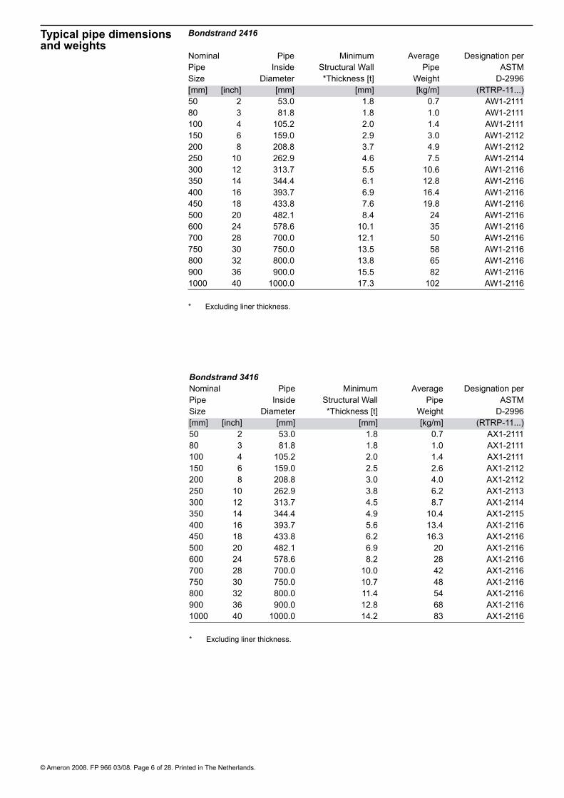
Typical pipe dimensions and weights
Bondstrand 2416
Nominal Pipe Minimum Average Designation perPipe Inside Structural Wall Pipe ASTMSize Diameter *Thickness [t] Weight D-2996[ mm] [inch] [mm] [mm] [kg/m] (RTRP-11...)50 2 53.0 1.8 0.7 AW1-211180 3 81.8 1.8 1.0 AW1-2111100 4 105.2 2.0 1.4 AW1-2111150 6 159.0 2.9 3.0 AW1-2112200 8 208.8 3.7 4.9 AW1-2112250 10 262.9 4.6 7.5 AW1-2114300 12 313.7 5.5 10.6 AW1-2116350 14 344.4 6.1 12.8 AW1-2116400 16 393.7 6.9 16.4 AW1-2116450 18 433.8 7.6 19.8 AW1-2116500 20 482.1 8.4 24 AW1-2116600 24 578.6 10.1 35 AW1-2116700 28 700.0 12.1 50 AW1-2116750 30 750.0 13.5 58 AW1-2116800 32 800.0 13.8 65 AW1-2116900 36 900.0 15.5 82 AW1-21161000 40 1000.0 17.3 102 AW1-2116
* Excluding liner thickness.
Bondstrand 3416 Nominal Pipe Minimum Average Designation perPipe Inside Structural Wall Pipe ASTMSize Diameter *Thickness [t] Weight D-2996[mm] [inch] [mm] [mm] [kg/m] (RTRP-11...)50 2 53.0 1.8 0.7 AX1-211180 3 81.8 1.8 1.0 AX1-2111100 4 105.2 2.0 1.4 AX1-2111150 6 159.0 2.5 2.6 AX1-2112200 8 208.8 3.0 4.0 AX1-2112250 10 262.9 3.8 6.2 AX1-2113300 12 313.7 4.5 8.7 AX1-2114350 14 344.4 4.9 10.4 AX1-2115400 16 393.7 5.6 13.4 AX1-2116450 18 433.8 6.2 16.3 AX1-2116500 20 482.1 6.9 20 AX1-2116600 24 578.6 8.2 28 AX1-2116700 28 700.0 10.0 42 AX1-2116750 30 750.0 10.7 48 AX1-2116800 32 800.0 11.4 54 AX1-2116900 36 900.0 12.8 68 AX1-21161000 40 1000.0 14.2 83 AX1-2116
* Excluding liner thickness.

© Ameron 2008. FP 966 03/08. Page 7 of 28. Printed in The Netherlands.
Span length Horizontal support for Bondstrand 2416 and 3416 at 21 °C Nominal Single Continuous Single Continuous Pipe Span* Span* Span* Span* Size 2416 2416 3416 3416 [mm] [inch] [m] [m] [m] [m] 50 2 2.9 3.6 2.6 3.480 3 3.2 4.1 3.0 3.8100 4 3.5 4.5 3.2 4.1150 6 4.2 5.3 3.8 4.8200 8 4.7 6.0 4.2 5.4250 10 5.3 6.7 4.7 6.0300 12 5.7 7.3 5.1 6.5350 14 6.0 7.7 5.3 6.8400 16 6.4 8.1 5.7 7.2450 18 6.7 8.5 6.0 7.6500 20 7.1 9.0 6.3 8.0600 24 7.7 9.8 6.8 8.7 700 28 8.5 10.7 7.5 9.5 750 30 8.8 11.1 7.8 9.9800 32 9.0 11.5 8.0 10.2900 36 9.6 12.1 8.5 10.81000 40 10.1 12.8 8.9 11.3
* Span recommendations are based on pipes filled with water having a density of 1000 kg/m3 and include no provisions for weights caused by valves, flanges or other heavy objects. At 93°C, span lengths are approx. 10% lower.
Bending Radius Minimum allowable for Bondstrand 2416 and 3416 at 21 °C Nominal Bending BendingPipe Radius RadiusSize 3416 2416 [mm] [inch] [m] [m] 50 2 11 1280 3 20 25100 4 27 42150 6 53 52200 8 83 67250 10 103 87300 12 125 106350 14 139 116400 16 159 135450 18 173 150500 20 192 169600 24 235 204700 28 279 253750 30 300 271800 32 321 291900 36 362 3301000 40 404 366
Note: Do not bend pipe until adhesive has cured. Sharper bends may create excessive stress concentrations.

© Ameron 2008. FP 966 03/08. Page 8 of 28. Printed in The Netherlands.
Filament-wound 90º elbows with integral Taper/Taper (2-40 inch) socket ends for adhesive bonding. Nominal Laying Overall AveragePipe Size Length (LL) Length (OL) Weight[mm] [inch] [mm] [mm] [kg]50 2 87 137 0.680 3 126 176 1.1100 4 155 205 2.1150 6 240 290 4,2200 8 315 395 12250 10 391 501 16300 12 463 603 26350 14 364 504 37400 16 402 572 53450 18 472 642 76500 20 523 723 125600 24 625 855 228700 28 726 956 238750 30 777 1037 290800 32 828 1118 364900* 36 929 1279 544900** 36 929 1189 4601000* 40 1040 1360 6101000** 40 1040 1270 530
* For Bondstrand 2416 only; ** For Bondstrand 3416 only.
Elbows 90º
Taper/Taper dimensions
Dimensions for adhesive Taper Spigots for adhesive Taper/Taper (2-40 inch) joints.
Nominal Taper Insertion Nominal Dia ofPipe Angle Depth Spigot SpigotSize Nose Thickn. at Nose X Ds nose Sd[mm] [inch] [degrees] [mm] [mm] [mm]50 2 2.5 50 1.0 55.280 3 2.5 50 1.0 83.8100 4 2.5 50 1.0 107.2150 6 2.5 50 1.0 161.0200 8 2.5 80 1.0 210.8250 10 2.5 110 1.0 264.9300 12 2.5 140 1.0 315.7350 14 2.5 140 1.5 347.4400 16 2.5 170 1.5 396.7450 18 2.5 170 1.5 436.8500 20 2.5 200 2.0 486.1600 24 2.5 230 2.5 583.6700 28 1.75 230 5.5 711.0750 30 1.75 260 6.0 762.0800 32 1.75 290 5.5 811.0900* 36 1.75 350 6.0 912.0900** 36 1.75 260 6.0 912.01000* 40 1.75 320 8.0 1016.01000** 40 1.75 230 8.0 1016.0
* For Bondstrand 2416 only;** For Bondstrand 3416 only.

© Ameron 2008. FP 966 03/08. Page 9 of 28. Printed in The Netherlands.
Elbows 22½º Filament-wound 22½°elbows with integral Taper/Taper (2-40 inch) socket ends for adhesive bonding. Nominal Laying Overall AveragePipe Length Length WeightSize (LL) (OL) [mm] [inch] [mm] [mm] [kg]50 2 29 79 0.480 3 37 87 0.6100 4 43 93 0.9150 6 60 110 1,4200 8 76 156 5,1250 10 68 178 9,7300 12 77 217 15,5350 14 71 211 21400 16 85 255 24450 18 106 276 39500 20 116 316 56600 24 136 366 93700 28 157 387 123750 30 167 427 158800 32 177 467 198900* 36 197 547 343900** 36 197 457 2661000* 40 234 554 4101000** 40 234 464 330
* For Bondstrand 2416 only; ** For Bondstrand 3416 only.
Elbows 45º Filament-wound 45° elbows with integral Taper/Taper (2-40 inch) socket ends for adhesive bonding. Nominal Laying Overall AveragePipe Length Length WeightSize (LL) (OL) [mm] [inch] [mm] [mm] [kg]50 2 45 95 0.580 3 61 111 0.9100 4 73 123 1.3150 6 106 156 2,5200 8 137 217 7,4250 10 169 279 12,4300 12 196 336 22350 14 125 265 29400 16 142 312 41450 18 204 374 54500 20 225 425 75600 24 268 498 130700 28 310 540 177750 30 331 591 226800 32 352 642 272900* 36 394 744 463900** 36 394 654 3821000* 40 450 770 5301000** 40 450 680 450
* For Bondstrand 2416 only; ** For Bondstrand 3416 only.

© Ameron 2008. FP 966 03/08. Page 10 of 28. Printed in The Netherlands.
Nominal Laying Overall Laying Overall AveragePipe Length Length Length Length WeightSize total run total run branch branch (LL1) (OL1) (LL2) (OL2) [mm] [inch] [mm] [mm] [mm] [mm] [kg]50 2 148 248 74 124 1.380 3 192 292 96 146 2.9100 4 230 330 115 165 4.0150 6 306 406 153 203 8.7200 8 376 536 188 268 21250 10 452 672 226 336 31300 12 528 808 264 404 50350 14 544 824 272 412 55400 16 590 930 295 465 87450 18 678 1018 339 509 103500 20 740 1140 370 570 209600 24 868 1328 434 664 351700 28 994 1454 497 727 476750 30 1046 1566 523 783 591800 32 1118 1698 559 849 727900* 36 1248 1948 624 974 1213900** 36 1248 1768 624 884 10801000* 40 1416 2056 708 1028 15771000** 40 1416 1876 708 938 1450
* For Bondstrand 2416 only; ** For Bondstrand 3416 only.
Equal Tees Filament-wound equal Tee with integral Taper/Taper (2-40 inch) socket ends for adhesive bonding.
Reducing Tees
Standard
Fabricated
Note: Regular numbers are filament wound tees; Italic numbers are fabricated.
Filament-wound standard and fabricated reducing tees with integral Taper/Taper (2-36 inch) socket ends for adhesive bonding.
Nominal Laying Overall Laying Overall AveragePipe Length Length Length Length WeightSize (LL1) (OL1) (LL2) (OL2) (runxrunxbranch) half run half run branch [mm] [inch] [mm] [mm] [mm] [mm] [kg]80x80x50 3x3x2 96 146 86 136 2.7100x100x50 4x4x2 115 165 99 149 3.8100x100x80 4x4x3 115 165 108 158 4.0150x150x50 6x6x2 153 203 124 174 8.0150x150x80 6x6x3 153 203 134 184 9.6150x150x100 6x6x4 153 203 140 190 9.6200x200x50 8x8x2 88 168 179 229 24.6200x200x80 8x8x3 188 268 159 209 16.0200x200x100 8x8x4 188 268 172 222 16.7200x200x150 8x8x6 188 268 178 228 13.2250x250x50 10x10x2 88 198 206 256 30250x250x80 10x10x3 100 210 206 256 32
*250x250x100 10x10x4 226 336 194 244 29250x250x150 10x10x6 226 336 204 254 28250x250x200 10x10x8 226 336 213 293 34300x300x50 12x12x2 88 228 232 282 35300x300x80 12x12x3 100 240 232 282 37
*300x300x100 12x12x4 264 404 216 266 43300x300x150 12x12x6 264 404 229 279 42300x300x200 12x12x8 264 404 239 319 45300x300x250 12x12x10 264 404 251 361 51350x350x50 14x14x2 88 228 247 297 37350x350x80 14x14x3 100 240 247 297 40

© Ameron 2008. FP 966 03/08. Page 11 of 28. Printed in The Netherlands.
Note: Regular numbers are filament wound tees; Italic numbers are fabricated
Standard
Fabricated
Reducing Tees (C’tnd) Filament-wound standard and fabricated reducing tees with integral Taper/Taper (2-36 inch) socket ends for adhesive bonding. Nominal Laying Overall Laying Overall AveragePipe Length Length Length Length WeightSize (LL1) (OL1) (LL2) (OL2) (runxrunxbranch) half run half run branch [mm] [inch] [mm] [mm] [mm] [mm] [kg]350x350x100 14x14x4 113 253 247 297 43350x350x150 14x14x6 272 412 254 304 41350x350x200 14x14x8 272 412 264 344 54350x350x250 14x14x10 272 412 277 387 62350x350x300 14x14x12 272 412 289 429 66400x400x50 16x16x2 88 258 272 322 50400x400x80 16x16x3 100 270 272 322 53400x400x100 16x16x4 113 283 272 322 56400x400x150 16x16x6 295 465 274 324 51400x400x200 16x16x8 295 465 283 363 56400x400x250 16x16x10 295 465 293 403 63400x400x300 16x16x12 295 465 305 445 67400x400x350 16x16x14 295 465 315 455 71450x450x50 18x18x2 88 258 292 342 54450x450x80 18x18x3 100 270 292 342 58450x450x100 18x18x4 113 283 292 342 61450x450x200 18x18x8 339 509 316 396 100450x450x250 18x18x10 339 509 329 439 104450x450x300 18x18x12 339 509 329 469 107450x450x350 18x18x14 339 509 330 470 137450x450x400 18x18x16 339 509 330 500 143500x500x50 20x20x2 88 288 316 366 59500x500x80 20x20x3 100 300 316 366 63500x500x100 20x20x4 113 313 316 366 67500x500x200 20x20x8 370 570 350 430 175500x500x250 20x20x10 370 570 355 465 180500x500x300 20x20x12 370 570 355 495 186500x500x350 20x20x14 370 570 356 496 188500x500x400 20x20x16 370 570 356 526 195500x500x450 20x20x18 370 570 365 535 200600x600x50 24x24x2 88 318 364 414 71600x600x80 24x24x3 100 330 364 414 75600x600x100 24x24x4 113 343 364 414 80600x600x300 24x24x12 434 664 405 545 211600x600x350 24x24x14 434 664 406 546 281600x600x400 24x24x16 434 664 406 576 220600x600x450 24x24x18 434 664 428 598 239600x600x500 24x24x20 434 664 428 628 279700x700x50 28x28x2 88 318 425 475 97700x700x80 28x28x3 100 330 425 475 102700x700x100 28x28x4 113 343 425 475 107700x700x350 28x28x14 497 727 475 615 413700x700x400 28x28x16 497 727 483 655 423700x700x450 28x28x18 497 727 483 653 428700x700x500 28x28x20 497 727 491 691 440700x700x600 28x28x24 497 727 491 721 458750x750x50 30x30x2 88 348 450 500 103750x750x80 30x30x3 100 360 450 500 109750x750x100 30x30x4 113 373 450 500 114750x750x350 30x30x14 532 783 501 641 506750x750x400 30x30x16 532 783 501 671 516750x750x450 30x30x18 532 783 509 679 522750x750x500 30x30x20 532 783 509 709 534750x750x600 30x30x24 532 783 517 747 555750x750x700 30x30x28 532 783 517 747 573
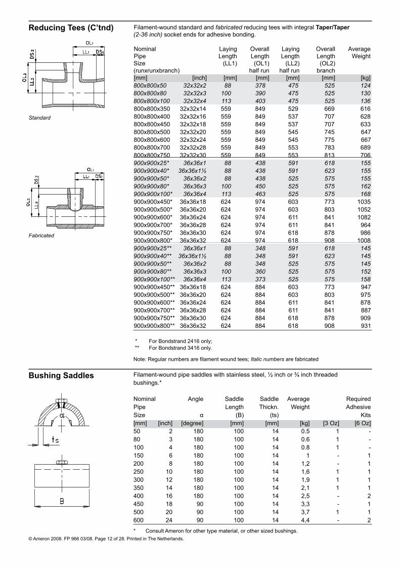
© Ameron 2008. FP 966 03/08. Page 12 of 28. Printed in The Netherlands.
Filament-wound pipe saddles with stainless steel, ½ inch or ¾ inch threaded bushings.* Nominal Angle Saddle Saddle Average Required Pipe Length Thickn. Weight Adhesive Size α (B) (ts) Kits [mm] [inch] [degree] [mm] [mm] [kg] [3 Oz] [6 Oz]50 2 180 100 14 0.5 1 - 80 3 180 100 14 0.6 1 - 100 4 180 100 14 0.8 1 - 150 6 180 100 14 1 - 1200 8 180 100 14 1,2 - 1250 10 180 100 14 1,6 1 1300 12 180 100 14 1,9 1 1350 14 180 100 14 2,1 1 1400 16 180 100 14 2,5 - 2450 18 90 100 14 3,3 - 1500 20 90 100 14 3,7 1 1600 24 90 100 14 4,4 - 2
Bushing Saddles
* Consult Ameron for other type material, or other sized bushings.
Reducing Tees (C’tnd)
Standard
Fabricated
Note: Regular numbers are filament wound tees; Italic numbers are fabricated
Filament-wound standard and fabricated reducing tees with integral Taper/Taper (2-36 inch) socket ends for adhesive bonding. Nominal Laying Overall Laying Overall AveragePipe Length Length Length Length WeightSize (LL1) (OL1) (LL2) (OL2) (runxrunxbranch) half run half run branch [mm] [inch] [mm] [mm] [mm] [mm] [kg]800x800x50 32x32x2 88 378 475 525 124800x800x80 32x32x3 100 390 475 525 130800x800x100 32x32x4 113 403 475 525 136800x800x350 32x32x14 559 849 529 669 616800x800x400 32x32x16 559 849 537 707 628800x800x450 32x32x18 559 849 537 707 633800x800x500 32x32x20 559 849 545 745 647800x800x600 32x32x24 559 849 545 775 667800x800x700 32x32x28 559 849 553 783 689800x800x750 32x32x30 559 849 553 813 706900x900x25* 36x36x1 88 438 591 618 155900x900x40* 36x36x1½ 88 438 591 623 155900x900x50* 36x36x2 88 438 525 575 155900x900x80* 36x36x3 100 450 525 575 162900x900x100* 36x36x4 113 463 525 575 168900x900x450* 36x36x18 624 974 603 773 1035900x900x500* 36x36x20 624 974 603 803 1052900x900x600* 36x36x24 624 974 611 841 1082900x900x700* 36x36x28 624 974 611 841 964900x900x750* 36x36x30 624 974 618 878 986900x900x800* 36x36x32 624 974 618 908 1008900x900x25** 36x36x1 88 348 591 618 145900x900x40** 36x36x1½ 88 348 591 623 145900x900x50** 36x36x2 88 348 525 575 145900x900x80** 36x36x3 100 360 525 575 152900x900x100** 36x36x4 113 373 525 575 158900x900x450** 36x36x18 624 884 603 773 947900x900x500** 36x36x20 624 884 603 803 975900x900x600** 36x36x24 624 884 611 841 878900x900x700** 36x36x28 624 884 611 841 887900x900x750** 36x36x30 624 884 618 878 909900x900x800** 36x36x32 624 884 618 908 931
* For Bondstrand 2416 only; ** For Bondstrand 3416 only.
© Ameron 2008. FP 966 03/08. Page 13 of 28. Printed in The Netherlands.
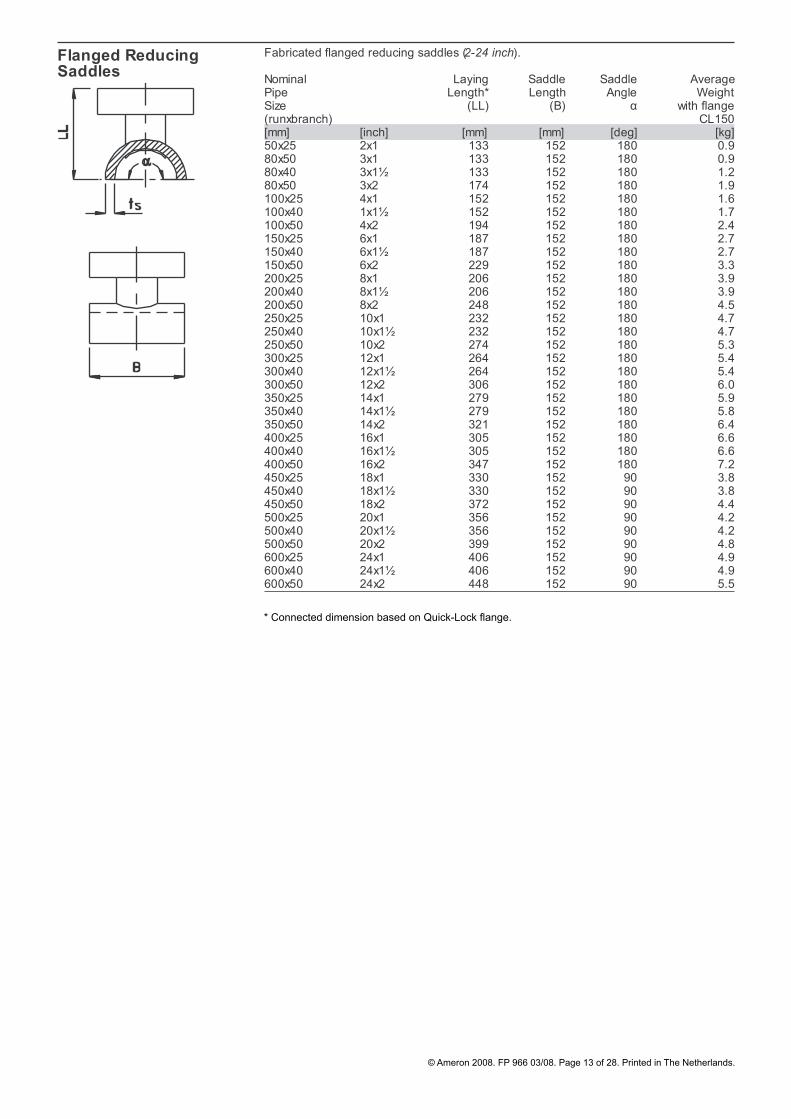
Fabricated flanged reducing saddles (2-24 inch).
Nominal Laying Saddle Saddle AveragePipe Length* Length Angle WeightSize (LL) (B) α with flange(runxbranch) CL150[mm] [inch] [mm] [mm] [deg] [kg]50x25 2x1 133 152 180 0.980x50 3x1 133 152 180 0.980x40 3x1½ 133 152 180 1.280x50 3x2 174 152 180 1.9100x25 4x1 152 152 180 1.6100x40 1x1½ 152 152 180 1.7100x50 4x2 194 152 180 2.4150x25 6x1 187 152 180 2.7150x40 6x1½ 187 152 180 2.7150x50 6x2 229 152 180 3.3200x25 8x1 206 152 180 3.9200x40 8x1½ 206 152 180 3.9200x50 8x2 248 152 180 4.5250x25 10x1 232 152 180 4.7250x40 10x1½ 232 152 180 4.7250x50 10x2 274 152 180 5.3300x25 12x1 264 152 180 5.4300x40 12x1½ 264 152 180 5.4300x50 12x2 306 152 180 6.0350x25 14x1 279 152 180 5.9350x40 14x1½ 279 152 180 5.8350x50 14x2 321 152 180 6.4400x25 16x1 305 152 180 6.6400x40 16x1½ 305 152 180 6.6400x50 16x2 347 152 180 7.2450x25 18x1 330 152 90 3.8450x40 18x1½ 330 152 90 3.8450x50 18x2 372 152 90 4.4500x25 20x1 356 152 90 4.2500x40 20x1½ 356 152 90 4.2500x50 20x2 399 152 90 4.8600x25 24x1 406 152 90 4.9600x40 24x1½ 406 152 90 4.9600x50 24x2 448 152 90 5.5
* Connected dimension based on Quick-Lockflange.
Flanged ReducingSaddles
α
Taper/Taper
* Connected dimension based on Quick-Lock flange.

© Ameron 2008. FP 966 03/08. Page 14 of 28. Printed in The Netherlands.
Concentric Reducers Filament-wound concentric reducers with integral Taper/Taper (2-36 inch) socket ends for adhesive bonding.
Nominal Laying Overall AveragePipe Length Length WeightSize (LL) (OL) (runxrun) [mm] [inch] [mm] [mm] [kg]80x50 3x2 74 174 0.8100x50 4x2 96 196 1.1100x80 4x3 94 194 1.3150x80 6x3 117 217 1.5150x100 6x4 124 224 1.8200x100 8x4 163 293 4.3200x150 8x6 129 259 4.3250x150 10x6 148 308 6.2250x200 10x8 135 325 6.9300x200 12x8 180 400 9.9300x250 12x10 167 417 10.8350x250 14x10 214 464 17.0350x300 14x12 208 488 16.8400x300 16x12 195 505 22400x350 16x14 183 493 23450x400 18x16 128 468 27500x400 20x16 249 619 36500x450 20x18 151 521 35600x400 24x16 486 886 70600x450 24x18 388 788 70600x500 24x20 267 697 70700x400 28x16 796 1196 141700x450 28x18 698 1098 140700x500 28x20 577 1007 142700x600 28x24 340 800 142750x400 30x16 915 1345 177750x450 30x18 817 1247 175750x500 30x20 696 1156 177750x600 30x24 459 949 177750x700 30x28 149 639 165800x400 32x16 1038 1498 216800x450 32x18 940 1400 214800x500 32x20 819 1309 217800x600 32x24 582 1102 217800x700 32x28 272 792 203800x750 32x30 153 703 207900x450** 36x18 1186 1706 358900x500** 36x20 1065 1615 362900x600** 36x24 828 1408 361900x700** 36x28 518 1098 300900x750** 36x30 399 1009 304900x800** 36x32 276 916 307900x450*** 36x18 1186 1616 314900x500*** 36x20 1065 1525 314900x600*** 36x24 828 1318 268900x700*** 36x28 518 1008 261900x750*** 36x30 399 919 265900x800*** 36x32 276 826 269
** For Bondstrand 2416 only;*** For Bondstrand 3416 only.

© Ameron 2008. FP 966 03/08. Page 15 of 28. Printed in The Netherlands.
Filament-wound eccentric reducers with integral Taper/Taper (2-36 inch) socket ends.
Nominal Laying Overall Eccentricity AveragePipe Size Length Length Weight(runxrun) (LL) (OL) (X)* [mm] [inch] [mm] [mm] [mm] [kg]80x50 3x2 140 240 14 0.8100x50 4x2 225 325 27 1.1100x80 4x3 120 220 12 1.3150x80 6x3 320 420 38 9.8150x100 6x4 230 330 27 5.3200x100 8x4 415 545 52 11.1200x150 8x6 215 345 25 9.0250x150 10x6 420 580 52 9.6250x200 10x8 235 425 27 10300x200 12x8 420 640 52 29300x250 12x10 220 470 25 11350x250 14x10 340 590 41 27350x300 14x12 150 430 16 22400x300 16x12 335 645 41 61400x350 16x14 215 525 25 22450x350 18x14 365 675 45 23450x400 18x16 180 520 20 90500x400 20x16 365 735 45 87500x450 20x18 215 585 25 75600x400 24x16 725 1125 93 115600x450 24x18 575 975 73 90600x500 24x20 390 820 48 142700x400 28x16 1195 1595 156 416700x450 28x18 1045 1445 136 153700x500 28x20 860 1290 111 223700x600 28x24 500 960 63 191750x400 30x16 1380 1810 181 259750x450 30x18 1235 1665 161 205750x500 30x20 1050 1510 136 186750x600 30x24 690 1180 88 134750x700 30x28 220 710 25 96800x600 32x24 875 1395 113 178800x700 32x28 405 925 50 142800x750 32x30 220 770 25 118900x600** 36x24 1250 1830 163 284900x700** 36x28 780 1360 100 260900x750** 36x30 590 1200 75 243900x800** 36x32 405 1045 50 271900x600*** 36x24 1250 1740 163 204900x700*** 36x28 780 1270 100 180900x750*** 36x30 590 1110 75 163900x800*** 36x32 405 955 50 191
** For Bondstrand 2416 only;*** For Bondstrand 3416 only.
Eccentric Reducers

© Ameron 2008. FP 966 03/08. Page 16 of 28. Printed in The Netherlands.
Filament-wound heavy-duty flanges with integral Taper/Taper (2-24 inch) socket end for adhesive bonding. Nominal Laying Overall Average weight Pipe Length Length ANSI ANSI DINSize (LL) (OL) B16.5 B16.5 2633 B16.47A B16.47A CL.150 CL.300 PN16[mm] [inch] [mm] [mm] [kg] [kg] [kg] 50 2 5 55 1.5 1.9 1.980 3 5 55 2.2 2.8 2.5100 4 5 55 2.9 4.1 2.8150 6 5 55 3,7 5.5 4.2 200 8 6 86 8,4 11.9 8.3 250 10 6 116 14,3 20 14.5 300 12 6 116 21 27 17.3 350 14 6 116 25 35 23 400 16 6 146 38 52 35 450 18 6 146 41 63 43 500 20 6 176 58 82 61
Note: Other drillings may be possible. Please consult Ameron;• Full-face elastomeric gaskets may be used suitable for the service pressure, service • temperature and fluid. Shore A durometer hardness of 60 ±5 is recom mended (3 mm thick). Compressed fibre gaskets (3 mm thick), compatible with pressure, temperature and medium may also be used. Mechanical properties should be in accordance with DIN 3754 (IT 400) or equal;For maximum bolt torque refer to the appropriate Bondstrand literature;• A torque-wrench must be used, since excessive torque may result in flange damage.•
Heavy-Duty Flanges

© Ameron 2008. FP 966 03/08. Page 17 of 28. Printed in The Netherlands.
Filament-wound stub-ends, O-ring sealed or flat faced, with integral Taper/Taper (2-40 inch) socket end, for adhesive bonding with loose steel ring flanges. Nominal Laying Overall Face Ring AveragePipe Length Length Diameter to Face Weight Size (LL) (OL) (RF) (H) Stub-end[mm] [inch] [mm] [mm] [mm] [mm] [kg]50 2 15 65 92 10 0.280 3 15 65 127 10 0.5100 4 15 65 157 12 0.8150 6 15 65 216 13 1.3200 8 15 95 270 20 2.6250 10 15 125 324 23 4.0300 12 15 155 378 26 5.9350 14 15 155 413 27 5.8400 16 20 190 470 32 9.6450 18 20 190 532 35 16.1500 20 20 220 580 39 19.8600 24 20 250 674 47 22700 28 20 250 800 51 26750 30 20 280 850 46 29800 32 20 310 900 48 34900* 36 20 370 1000 53 41900** 36 20 280 1000 53 361000* 40 20 250 1100 69 441000** 40 20 340 1100 69 37
Note: Flat faced stub-ends can be sealed using reinforced elastomeric, compressed fiber or steel • reinforced rubber gaskets, depending on size; Make sure that when using O-ring sealed stub-end, its counter flange is compatible, e.g. use a • flat faced stub-end (without O-ring groove) or another flat surface flange as counter flange.
Nominal ANSI Average ANSI Average DIN 2633 Average Pipe B16.5 Weight B16.5 Weight WeightSize CLASS.150 CLASS.300 PN 16 (D) (D) (D) [mm] [inch] [mm] [kg] [mm] [kg] [mm] [kg]50 2 19.0 1.8 22.2 2.5 18 2.280 3 23.8 3.2 28.6 4.8 20 3.0100 4 23.8 4.2 28.6 7.0 20 3.1150 6 25,5 5,2 36.5 12.2 23 5.1200 8 28,8 8,5 41.3 18.3 27 7.3250 10 35,6 13,5 47.6 26 32 11.8300 12 40 23 50.8 39 35 15.4350 14 41,6 32 54 56 40 26400 16 47,9 42 58.2 70 44 33450 18 50,2 40 63.6 87 50 41500 20 52 51 66.5 104 54 60600 24 63,7 86 78.4 183 63 72700 28 69 100 95 213 59 102750 30 71,6 117 99.9 229 - -800 32 76,9 154 106 289 66 106900 36 85,4 197 117.7 424 71 1251000 40 94 303 103 439 82 291
Note: Ring flanges will standard be made from galvanised steel. Other materials are available on • request;Other drillings are available. Please consult Ameron;• For maximum bolt-torque please refer to the appropriate Bondstrand Literature.•
Steel Ring Flanges forStub-ends
Stub-ends
© Ameron 2008. FP 966 03/08. Page 18 of 28. Printed in The Netherlands.
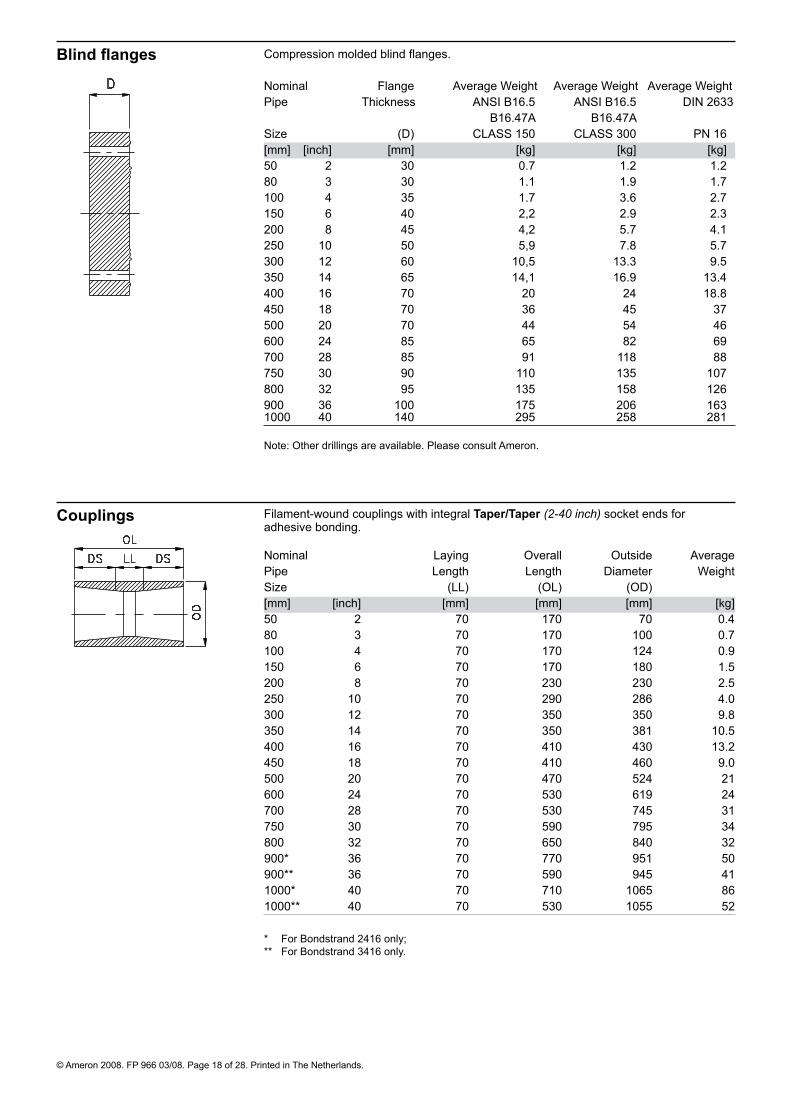
Compression molded blind flanges. Nominal Flange Average Weight Average Weight Average WeightPipe Thickness ANSI B16.5 ANSI B16.5 DIN 2633 B16.47A B16.47ASize (D) CLASS 150 CLASS 300 PN 16[mm] [inch] [mm] [kg] [kg] [kg]50 2 30 0.7 1.2 1.280 3 30 1.1 1.9 1.7100 4 35 1.7 3.6 2.7150 6 40 2,2 2.9 2.3200 8 45 4,2 5.7 4.1250 10 50 5,9 7.8 5.7300 12 60 10,5 13.3 9.5350 14 65 14,1 16.9 13.4400 16 70 20 24 18.8450 18 70 36 45 37500 20 70 44 54 46600 24 85 65 82 69700 28 85 91 118 88750 30 90 110 135 107800 32 95 135 158 126900 36 100 175 206 1631000 40 140 295 258 281
Note: Other drillings are available. Please consult Ameron.
Blind flanges
Nominal Laying Overall Outside AveragePipe Length Length Diameter WeightSize (LL) (OL) (OD) [mm] [inch] [mm] [mm] [mm] [kg]50 2 70 170 70 0.480 3 70 170 100 0.7100 4 70 170 124 0.9150 6 70 170 180 1.5200 8 70 230 230 2.5250 10 70 290 286 4.0300 12 70 350 350 9.8350 14 70 350 381 10.5400 16 70 410 430 13.2450 18 70 410 460 9.0500 20 70 470 524 21600 24 70 530 619 24700 28 70 530 745 31750 30 70 590 795 34800 32 70 650 840 32900* 36 70 770 951 50900** 36 70 590 945 411000* 40 70 710 1065 861000** 40 70 530 1055 52
* For Bondstrand 2416 only;** For Bondstrand 3416 only.
Filament-wound couplings with integral Taper/Taper (2-40 inch) socket ends for adhesive bonding.
Couplings

© Ameron 2008. FP 966 03/08. Page 19 of 28. Printed in The Netherlands.
Nipples Filament-wound nipples with integral Taper/Taper (2-40 inch) spigot ends for adhesive bonding.
Nominal Laying Gap AveragePipe Length * WeightSize (LL) [mm] [inch] [mm] [mm] [kg]50 2 125 25 0.180 3 125 25 0.1100 4 125 25 0.1150 6 125 25 0.3200 8 190 30 0.7250 10 250 30 1.3300 12 320 40 2.4350 14 320 40 3.0400 16 380 40 4.6450 18 400 60 5.6500 20 460 60 8.3600 24 520 60 13.3700 28 520 60 19.7750 30 580 60 26800 32 640 60 30900** 36 760 60 39900*** 36 580 60 311000** 40 700 60 541000*** 40 520 60 35
* Remaining gap after bonding (is distance between the edges of the socket ends);** For Bondstrand 2416 only;*** For Bondstrand3416 only.
Support Saddles Filament-wound pipe saddles for wear, support and anchor.
Nominal Saddle Saddle Saddle Required Saddle Required Pipe Angle Thickn. Weight Adhesive Weight Adhesive Size α ts B=100mm Kits B=150mm Kits[mm] [inch] [degree] [mm] [kg] [3 and 6 Oz] [kg] [3 and 6 Oz] 50 2 180 14 0.4 ½ - 0.6 1 -80 3 180 14 0.5 ½ - 0.8 1 -100 4 180 14 0.7 ½ - 1.1 1 -150 6 180 14 0.9 1 - 1.4 - 1200 8 180 14 1.1 1 - 1.7 - 1250 10 180 14 1.5 - 1 2.3 - 1300 12 180 14 1.8 - 1 2.7 - 1350 14 180 14 2 - 1 3.0 - 1400 16 180 14 2.4 1 1 3.6 - 2450 18 180 16 - - - 3.2 1 1500 20 180 16 - - - 3.6 1 1600 24 180 16 - - - 4.3 1 1700 28 180 16 - - - 5.1 - 2750 30 180 16 - - - 5.5 - 2800 32 180 16 - - - 5.8 - 3900 36 180 16 - - - 6.5 - 41000 40 180 16 - - - 7.1 - 5 Note:
Filament-wound support saddles are intended for protection of pipe at supports and clamps, • as well as for anchoring purposes; Support and anchor saddles are standard 180°;• Saddles are supplied in standard lengths of 100 mm and 150 mm;• For special saddle -lengths, -thickness and/or angles consult Ameron;• Wear saddles are standard 90°. 90° saddle weights are 50% of value shown.•
α
α

© Ameron 2008. FP 966 03/08. Page 20 of 28. Printed in The Netherlands.
Adhesive Number of Adhesive Kits per joint with integral Taper/Taper (2-40 inch) socket ends for adhesive bonding. Nominal Required Minimum number Pipe Adhesive Kit of Adhesive Kits Size Size required per joint [mm] [inch] [cm3] [Oz] nr. 50 2 89 3 ¹/380 3 89 3 ¹/3100 4 89 3 ½150 6 89 3 ½ 200 8 89 3 1 250 10 177 6 1 300 12 177 6 1 350 14 177 6 2 400 16 177 6 2 450 18 177 6 2 500 20 177 6 3 600 24 177 6 3 700 28 177 6 4750 30 177 6 5 800 32 177 6 6 900* 36 177 6 7 900** 36 177 6 61000* 40 177 6 71000** 40 177 6 5
* For Bondstrand 2416 only;** For Bondstrand 3416 only.
Note: Adhesive Kits should never be split. If remainder is not used for other joints made at the • same time, the surplus must be discarded;Required adhesive for saddles is shown in the dimension table of the respective saddles;• For type of adhesive to be used, please refer to the Bondstrand® Corrosion Guide;• Saddles and Taper/Taper adhesive bonded joints require different types of adhesive.•

© Ameron 2008. FP 966 03/08. Page 21 of 28. Printed in The Netherlands.
Filament-wound 90º elbows with integral Key-Lock (4-24 inch) or fabricated Key-Lock (2-3 Inch) socket ends.
Nominal Laying Overall AveragePipe Size Length (LL) Length (OL) Weight[mm] [inch] [mm] [mm] [kg]50 2 298 318 4.680 3 337 357 6.3100 4 145 165 4.3150 6 176 203 9.8200 8 332 369 22.6250 10 391 431 36.6300 12 467 513 39.7350 14 543 592 77.3400 16 607 721 90.0450 18 566 660 113.0500 20 620 719 142.6600 24 713 801 172.9
Elbows 90º
Key-Lock dimensions
Dimensions for Key-Lock (2-24 inch) mechanical joints. Nominal Number Joint Key to Key to Key Key* O-ring**Pipe of diameter edge edge distance dimensions dimensionsSize keys socket ends spigot end (2keys) OD D N Z[mm] [inch] [mm] [mm] [mm] [mm] [diax1gth] [corexdia] 50 2 1 74.1 20 45 - 6x305 7x59.780 3 1 103.0 20 45 - 6x400 7x88.3100 4 1 128.9 20 45 - 6x483 7x113.7150 6 1 183.3 27 56 - 8x660 10x161.3200 8 1 243.6 36.5 68.5 - 10x840 10x208.9250 10 1 290.5 39.5 72 - 12x1090 10x266.1300 12 1 345.4 46 85 - 15x1270 12.5x316.9350 14 1 385.5 49 87.5 - 15x1360 12.5x342.3400 16 2 433.5 51 90.5 63.5 18x1585 12.5x393.1450 18 2 481.6 46 94 48 15x1570 15x445500 20 2 529.8 49 97 50.5 15x1930 15x490600 24 2 626.3 43 94 44.5 18x2240 18x580
* Key material is nylon** O-rings are available in NBR or EPDM. For other O-ring material contact Ameron
1-key with adapters and couplings
1-key
2-key

© Ameron 2008. FP 966 03/08. Page 22 of 28. Printed in The Netherlands.
Equal Tees Filament-wound equal Tee with integral Key-Lock (4-24 inch) or fabricated Key-Lock (2-3 Inch) socket ends. Nominal Laying Overall Laying Overall AveragePipe Length Length Length Length WeightSize total run total run branch branch (LL1) (OL1) (LL2) (OL2) [mm] [inch] [mm] [mm] [mm] [mm] [kg]50 2 5701 610 285 305 6.980 3 614 654 307 327 10.6100 4 290 330 145 165 3.9150 6 372 426 186 213 11.1200 8 454 527 227 264 20250 10 524 603 262 302 30300 12 606 698 303 349 44350 14 722 820 361 410 58400 16 762 991 381 496 95450 18 866 1054 433 527 148 500 20 932 1130 466 565 180 600 24 1096 1270 548 635 218
Elbows 45º Filament-wound 45° elbows with integral Key-Lock (2-24 inch) or fabricated Key-Lock (2-3 Inch) socket ends. Nominal Laying Overall AveragePipe Length Length WeightSize (LL) (OL) [mm] [inch] [mm] [mm] [kg]50 2 256 276 4.480 3 272 292 6.0100 4 82 102 2.5150 6 106 133 6.9200 8 209 246 17.6250 10 241 281 22300 12 285 331 37350 14 333 382 48400 16 368 483 64450 18 300 394 78500 20 319 419 97600 24 357 445 115
1-key with adapters and couplings
1-key with adapters and couplings
1-key
2-key
1-key
2-key

© Ameron 2008. FP 966 03/08. Page 23 of 28. Printed in The Netherlands.
Reducing Tees
2x1-Key
2x2-Key
Filament-wound standard reducing tees with integral Key-Lock (6-24 inch) socket ends.
Nominal Laying Overall Laying Overall AveragePipe Length Length Length Length WeightSize (LL1) (OL1) (LL2) (OL2) (runxrunxbranch) half run half run branch [mm] [inch] [mm] [mm] [mm] [mm] [kg]150x150x100 6x6x4 186 213 172 192 9.8200x200x100 8x8x4 227 264 198 218 19.3200x200x150 8x8x6 227 264 212 239 20250x250x100 10x10x4 262 302 226 246 24250x250x150 10x10x6 262 302 248 267 35250x250x200 10x10x8 262 302 256 293 37300x300x100 12x12x4 303 349 258 278 39300x300x150 12x12x6 303 349 268 295 39300x300x200 12x12x8 303 349 283 320 41300x300x250 12x12x10 303 349 290 330 43350x350x150 14x14x6 361 410 288 315 55350x350x200 14x14x8 361 410 303 340 57350x350x250 14x14x10 361 410 310 350 60350x350x300 14x14x12 361 410 323 369 60*400x400x150 *16x16x6 380 494 312 339 95*400x400x200 *16x16x8 380 494 326 363 97*400x400x250 *16x16x10 380 494 333 373 99*400x400x300 *16x16x12 380 494 348 394 102*400x400x350 *16x16x14 380 494 385 434 109*450x450x200 *18x18x8 433 527 352 389 126*450x450x250 *18x18x10 433 527 359 399 129*450x450x300 *18x18x12 433 527 372 418 131*450x450x350 *18x18x14 433 527 409 458 137*500x500x250 *20x20x10 466 565 383 423 158*500x500x300 *20x20x12 466 565 396 442 167*500x500x350 *20x20x14 466 565 433 482 173*600x600x350 *24x24x14 548 635 482 *531 236600x600x400 24x24x16 548 635 487 602 247600x600x450 24x24x18 548 635 554 648 259600x600x500 24x24x20 548 635 565 665 267* Run is 2-key, branch is 1 key
1x1-Key

© Ameron 2008. FP 966 03/08. Page 24 of 28. Printed in The Netherlands.
Flanges
Couplings
Filament-wound flanges with fabricated Key-Lock (2-24 inch) spigot end.
Nominal Laying Overall Flange Averagepipe Length Length Thickness Weight*Size (LL) (OL) (D) [mm] [inch] [mm] [mm] [mm] [kg]50 2 116 161 55 1.880 3 116 161 55 2.7100 4 118 163 55 3.6150 6 126 182 55 4.7200 8 164 232 86 10.3250 10 194 266 116 17.0300 12 232 317 116 25350 14 243 330 116 31400 16 336 426 146 46450 18 331 425 146 53500 20 361 458 176 72600 24 372 466 206 104
* The above weights are based on CL150 Flange
Note: Other drillings may be possible. Please consult Ameron;• Full-face elastomeric gaskets may be used suitable for the service pressure, service • temperature and fluid. Shore A durometer hardness of 60 ±5 is recom mended (3 mm thick). Compressed fibre gaskets (3 mm thick), compatible with pressure, temperature and medium may also be used. Mechanical properties should be in accordance with DIN 3754 (IT 400) or equal;For maximum bolt torque refer to the appropriate Bondstrand literature;• A torque-wrench must be used, since excessive torque may result in flange damage.•
Filament-wound couplings with integral Key-Lock (2-24 inch) socket ends.
Nominal Laying Overall Outside Averagepipe Length Length Diameter WeightSize (LL) (OL) (OO)[mm] [inch] [mm] [mm] [mm] [kg]50 2 100 140 98 0.880 3 100 140 127 1.0100 4 100 140 152 2.2150 6 127 181 226 4.3200 8 152 225 275 6.6250 10 163 242 337 9.6300 12 186 278 388 11.6350 14 191 289 435 15.8400 16 197 426 505 38450 18 204 392 534 27500 20 210 409 584 32600 24 200 375 673 29
1-Key
2-Key
1-Key
2-Key
OD
OD

© Ameron 2008. FP 966 03/08. Page 25 of 28. Printed in The Netherlands.
Nipples Filament-wound nipples with integral Key-Lock (2-24 inch) spigot end.
Nominal Laying Overall Averagepipe Length Length WeightSize (LL) (OL) [mm] [inch] [mm] [mm] [kg]50 2 70 160 0.580 3 70 160 0.8100 4 70 160 1.1150 6 88 200 2.0200 8 103 240 3.4250 10 111 255 4.9300 12 125 295 7.6350 14 130 305 11.7400 16 259 440 18.3450 18 222 410 23500 20 236 430 26600 24 212 400 28
1-Key
2-Key

© Ameron 2008. FP 966 03/08. Page 26 of 28. Printed in The Netherlands.
Adapter KLMxTF
Adapter KLMxTM
Filament-wound adapter with integral Key-Lock (2-24 inch) spigot end by integral Taper/Taper socket end for adhesive bonding.
Nominal Laying Overall Averagepipe Length Length WeightSize (LL) (OL) [mm] [inch] [mm] [mm] [kg]50 2 5 100 0.380 3 5 100 0.5100 4 5 100 0.7150 6 4 110 1.0200 8 1.5 150 1.9250 10 3 185 2.7300 12 5 230 4.0350 14 17.5 245 6.4400 16 79.5 340 8.2450 18 61 325 11.5500 20 83 380 13.9600 24 76 400 16.9
Filament-wound adapter with integral Key-Lock (2-24 inch) spigot end by integral Taper/Taper spigot end for adhesive bonding.
Nominal Laying Overall Averagepipe Length Length WeightSize (LL) (OL) [mm] [inch] [mm] [mm] [kg]50 2 115 160 0.380 3 116 161 0.5100 4 117 162 0.7150 6 125 181 1.0200 8 162 231 1.9250 10 193 265 2.7300 12 231 316 4.0350 14 240 327 6.4400 16 334 424 8.2450 18 321 415 11.5500 20 355 452 13.9600 24 366 460 16.9
1-Key
2-Key
1-Key
2-Key
© Ameron 2008. FP 966 03/08. Page 27 of 28. Printed in The Netherlands.
Engineering design &installation
Consult de following literature for recommendations about design, installation and use of Bondstrand pipe, fittings and flanges:
Assembly Instructions for Key-Lock adhesive-bonded joints FP 161Assembly Instructions for Taper/Taper adhesive-bonded joints FP 564Assembly Instructions for Bondstrand fiberglass flanges FP 196Bondstrand Corrosion Guide for fiberglass pipe and tubing FP 132Bondstrand Pipe Shaver Overview FP 599
Please consult Ameron for the latest version of the above mentioned literature.
Note: Elbows with non-standard angles, non-standard drilled flanges, multi branch tees and special spools are available on request, please consult Ameron.
Bondstrand pipe systems are designed for hydrostatic testing with water at 150% of rated pressure.
The maximum allowable surge pressure is 150% of rated pressure.
1 psi = 6895 Pa = 0.07031 kg/cm2
1 bar = 105Pa = 14.5 psi = 1.02 kg/cm2
1 MPa = 1 N/mm2 = 145 psi = 10.2 kg/cm2 1 inch = 25.4 mm1 Btu.in/ft2h°F = 0.1442 W/mK°C = 5/9 (°F-32)
This product literature and the recommendations for usage it contains are based on test data reasonably believed to be reliable. It is intended that this literature be used by personnel having specialised training in accordance with currently acceptable industry practice and normal operating conditions. Variation in environment, changes in operating procedures, or extrapolation of data may cause unsatisfactory results. We recommend that your engineers verify the suitability of this product for your intended application. Since we have no control over the conditions of service, we expressly disclaim responsibility for the results obtained or for any consequential or incidental damages of any kind incurred.
Field testing
Surge pressure
Conversions
Important notice
Specials

© Ameron 2008. FP 966 03/08. Page 28 of 28. Printed in The Netherlands.
EuropeAmeron B.V.Fiberglass-Composite Pipe P.O. Box 64190 CA GeldermalsenThe NetherlandsPhone: +31 345 587 587Fax: +31 345 587 561E-mail: [email protected]
Group Headquarters Ameron International Corporation Fiberglass-Composite Pipe Division9720 Cypresswood Drive, Suite 325 Houston, Texas 77070 - U.S.A.Phone: +1 832 912 8282 Fax: +1 832 912 9393E-mail: [email protected]
Asia & Middle EastAmeron (Pte) Ltd.No. 7A, Tuas Avenue 3JurongSingapore 639407Phone: +65 6861 6118Fax: +65 6862 1302/6861 7834E-mail: [email protected]
Centron International, Inc.P.O. Box 490600 FM 1195 SouthMineral Wells - Texas 76068U.S.A.Phone: +1 940 325 1341Fax: +1 940 325 9681E-mail: [email protected]
North AmericaAmeron International Corporation1004 Ameron RoadP.O. Box 878Burkburnett, Texas 76364U.S.A.Phone: +1 940 569 1471Fax: +1 940 569 2764
Website: http://www.ameron-fpg.com
South AmericaAmeron Polyplaster Industria e comerciode Tubos Ltda. Rua Aurora Maria daConceição 958 - Bairro Santa CruzCEP 32.530-050-Betim-MGBrasilPhone: +55 31 3592 1399Fax: +55 31 3592 1057E-mail: [email protected]