GRAYSCALE IMAGE ANALYSIS USING MORPHOLOGICAL...
6
ISSN: 2347-971X (online) International Journal of Innovations in Scientific and ISSN: 2347-9728(print) Engineering Research (IJISER) www.ijiser.com 13 Vol 1 Issue 1 JAN 2014/103 GRAYSCALE IMAGE ANALYSIS USING MORPHOLOGICAL FILTERING S.Sindhuja Arasu Engineering College, Kumbakonam-612001 [email protected] Abstract: The capability of extracting moving objects from a video sequence captured using a static camera is a typical first step in visual surveillance. The idea of background subtraction is to subtract or difference the current image from a reference background model. This paper proposes a new method to detect moving object based on background subtraction. First of all, we establish a reliable background updating model based on statistical and use a dynamic optimization threshold method to obtain a more complete moving object. Here we have written the core processor Microblaze is designed in VHDL (VHSIC hardware description language), implemented using XILINX ISE 8.1 Design suite the algorithm is written in Impulse C Language and tested in SPARTAN-3 FPGA kit by interfacing a test circuit with the PC using the RS232 cable. The test results are seen to be satisfactory. The area taken and the speed of the algorithm are also evaluated. Keywords: UART; VHDL; Soft core; Microblaze; Morphological Image Filtering, Segmentation. 1. INTRODUCTION Image segmentation is one of the most important categories of image processing. The purpose of image segmentation is to divide an original image into homogeneous regions. It can be applied as a pre- processing stage for other image processing methods. There exist several approaches for image segmentation methods for image processing. The after sheds transformation is studied in this thesis as a particular method of a region-based approach to the segmentation of an image. The complete transformation incorporates a pre-processing and post-processing stage that deals with embedded problems such as edge ambiguity and the output of a large number of regions. Multiscale Morphological Gradient (MMG) and Region Adjacency Graph (RAG) are two methods that are pre-processing and post-processing stages, respectively. RAG incorporates dissimilarity criteria to merge adjacent homogeneous regions. In this thesis, the proposed system has been applied to a set of co-aligned images, which include a pair of intensity and range images. It is expected that the hidden edges within the intensity image can be detected by observing range data or vice versa. Also it is expected that the contribution of the range image in region merging can compensate for the dominance of shadows within the intensity image regardless of the original intensity of the object. Image processing and analysis is an important area in the field of robotics. This is particularly true for the operation of autonomous vehicles. The operation of an autonomous vehicle is based on first acquiring data that describe its environment. Indeed, the motion planning and control of a fully autonomous vehicle requires an intelligent controller to be able to make decisions to allow the autonomous vehicle to maneuver in an unknown field based on these data. These data sets include range data, 2D images, and position measurements. This data is used to identify and avoid obstacles and to map the surrounding terrain. The elements of an image analysis system are shown in Fig.1. Image analysis usually starts with a pre- processing stage, which includes operations such as noise reduction. For the actual recognition stage, segmentation should be done before it to extract out only the part that has useful information. Image segmentation is a primary and critical component of image analysis. The quality of the final results of an image analysis could depend on the segmentation step. On the other hand, segmentation is one of the most difficult tasks in image processing, especially automatic image segmentation.
Transcript of GRAYSCALE IMAGE ANALYSIS USING MORPHOLOGICAL...

ISSN: 2347-971X (online) International Journal of Innovations in Scientific and ISSN: 2347-9728(print) Engineering Research (IJISER)
www.ijiser.com 13 Vol 1 Issue 1 JAN 2014/103
GRAYSCALE IMAGE ANALYSIS USING MORPHOLOGICAL FILTERING
S.Sindhuja
Arasu Engineering College, Kumbakonam-612001
Abstract: The capability of extracting moving objects from a video sequence captured using a static camera is a
typical first step in visual surveillance. The idea of background subtraction is to subtract or difference the current
image from a reference background model. This paper proposes a new method to detect moving object based on
background subtraction. First of all, we establish a reliable background updating model based on statistical and use a
dynamic optimization threshold method to obtain a more complete moving object. Here we have written the core
processor Microblaze is designed in VHDL (VHSIC hardware description language), implemented using XILINX
ISE 8.1 Design suite the algorithm is written in Impulse C Language and tested in SPARTAN-3 FPGA kit by
interfacing a test circuit with the PC using the RS232 cable. The test results are seen to be satisfactory. The area
taken and the speed of the algorithm are also evaluated.
Keywords: UART; VHDL; Soft core; Microblaze; Morphological Image Filtering, Segmentation.
1. INTRODUCTION
Image segmentation is one of the most important
categories of image processing. The purpose of image
segmentation is to divide an original image into
homogeneous regions. It can be applied as a pre-
processing stage for other image processing methods.
There exist several approaches for image segmentation
methods for image processing. The after sheds
transformation is studied in this thesis as a particular
method of a region-based approach to the segmentation
of an image. The complete transformation incorporates
a pre-processing and post-processing stage that deals
with embedded problems such as edge ambiguity and
the output of a large number of regions. Multiscale
Morphological Gradient (MMG) and Region Adjacency
Graph (RAG) are two methods that are pre-processing
and post-processing stages, respectively. RAG
incorporates dissimilarity criteria to merge adjacent
homogeneous regions.
In this thesis, the proposed system has been
applied to a set of co-aligned images, which include a
pair of intensity and range images. It is expected that
the hidden edges within the intensity image can be
detected by observing range data or vice versa. Also it
is expected that the contribution of the range image in
region merging can compensate for the dominance of
shadows within the intensity image regardless of the
original intensity of the object.
Image processing and analysis is an important area in
the field of robotics. This is particularly true for the
operation of autonomous vehicles. The operation of an
autonomous vehicle is based on first acquiring data that
describe its environment. Indeed, the motion planning
and control of a fully autonomous vehicle requires an
intelligent controller to be able to make decisions to
allow the autonomous vehicle to maneuver in an
unknown field based on these data. These data sets
include range data, 2D images, and position
measurements. This data is used to identify and avoid
obstacles and to map the surrounding terrain.
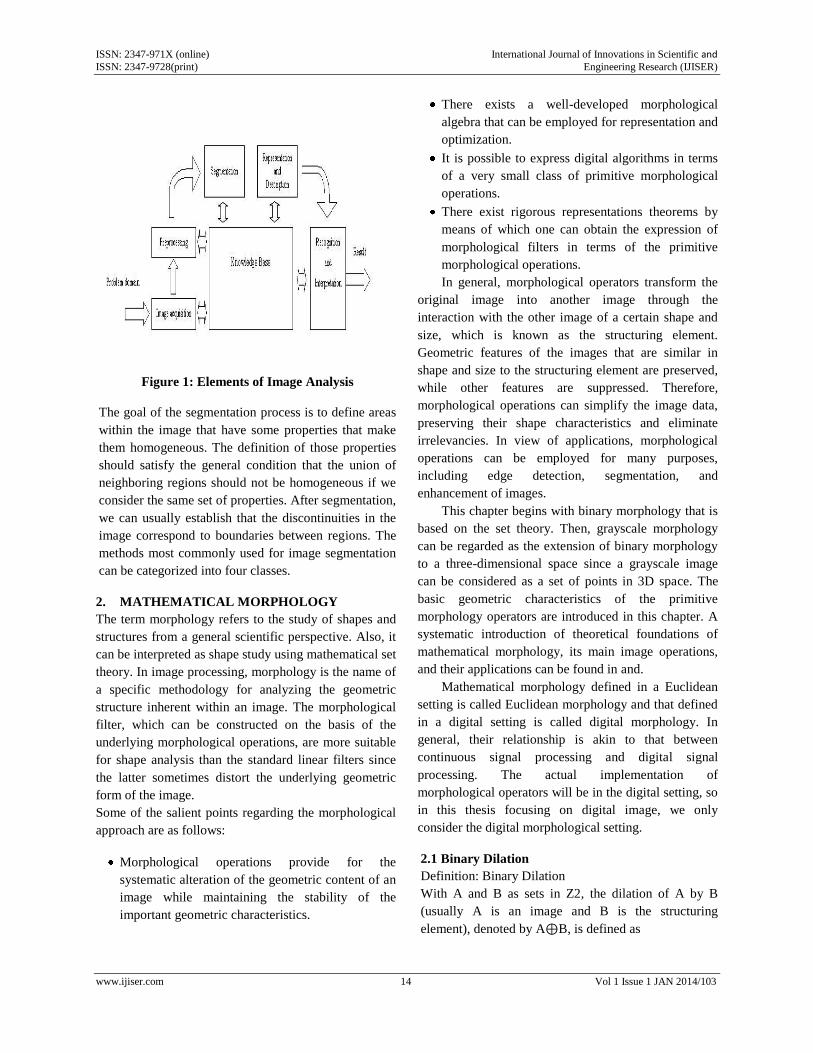
The elements of an image analysis system are
shown in Fig.1. Image analysis usually starts with a pre-
processing stage, which includes operations such as
noise reduction. For the actual recognition stage,
segmentation should be done before it to extract out
only the part that has useful information. Image
segmentation is a primary and critical component of
image analysis. The quality of the final results of an
image analysis could depend on the segmentation step.
On the other hand, segmentation is one of the most
difficult tasks in image processing, especially automatic
image segmentation.
ISSN: 2347-971X (online) International Journal of Innovations in Scientific and ISSN: 2347-9728(print) Engineering Research (IJISER)
www.ijiser.com 14 Vol 1 Issue 1 JAN 2014/103
Figure 1: Elements of Image Analysis
The goal of the segmentation process is to define areas
within the image that have some properties that make
them homogeneous. The definition of those properties
should satisfy the general condition that the union of
neighboring regions should not be homogeneous if we
consider the same set of properties. After segmentation,
we can usually establish that the discontinuities in the
image correspond to boundaries between regions. The
methods most commonly used for image segmentation
can be categorized into four classes.
2. MATHEMATICAL MORPHOLOGY
The term morphology refers to the study of shapes and
structures from a general scientific perspective. Also, it
can be interpreted as shape study using mathematical set
theory. In image processing, morphology is the name of
a specific methodology for analyzing the geometric
structure inherent within an image. The morphological
filter, which can be constructed on the basis of the
underlying morphological operations, are more suitable
for shape analysis than the standard linear filters since
the latter sometimes distort the underlying geometric
form of the image.
Some of the salient points regarding the morphological
approach are as follows:
Morphological operations provide for the
systematic alteration of the geometric content of an
image while maintaining the stability of the
important geometric characteristics.
There exists a well-developed morphological
algebra that can be employed for representation and
optimization.
It is possible to express digital algorithms in terms
of a very small class of primitive morphological
operations.
There exist rigorous representations theorems by
means of which one can obtain the expression of
morphological filters in terms of the primitive
morphological operations.
In general, morphological operators transform the
original image into another image through the
interaction with the other image of a certain shape and
size, which is known as the structuring element.
Geometric features of the images that are similar in
shape and size to the structuring element are preserved,
while other features are suppressed. Therefore,
morphological operations can simplify the image data,
preserving their shape characteristics and eliminate
irrelevancies. In view of applications, morphological
operations can be employed for many purposes,
including edge detection, segmentation, and
enhancement of images.
This chapter begins with binary morphology that is
based on the set theory. Then, grayscale morphology
can be regarded as the extension of binary morphology
to a three-dimensional space since a grayscale image
can be considered as a set of points in 3D space. The
basic geometric characteristics of the primitive
morphology operators are introduced in this chapter. A
systematic introduction of theoretical foundations of
mathematical morphology, its main image operations,
and their applications can be found in and.
Mathematical morphology defined in a Euclidean
setting is called Euclidean morphology and that defined
in a digital setting is called digital morphology. In
general, their relationship is akin to that between
continuous signal processing and digital signal
processing. The actual implementation of
morphological operators will be in the digital setting, so
in this thesis focusing on digital image, we only
consider the digital morphological setting.
2.1 Binary Dilation
Definition: Binary Dilation
With A and B as sets in Z2, the dilation of A by B
(usually A is an image and B is the structuring
element), denoted by A⊕B, is defined as
ISSN: 2347-971X (online) International Journal of Innovations in Scientific and ISSN: 2347-9728(print) Engineering Research (IJISER)
www.ijiser.com 15 Vol 1 Issue 1 JAN 2014/103
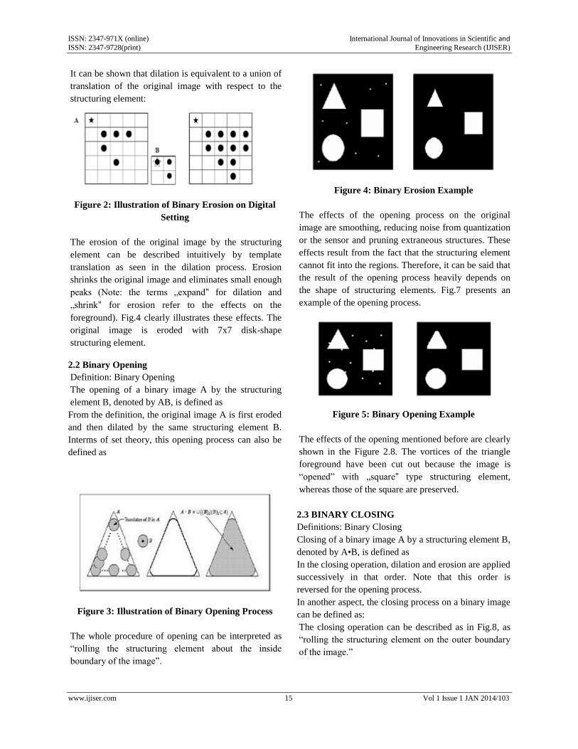
It can be shown that dilation is equivalent to a union of
translation of the original image with respect to the
structuring element:
Figure 2: Illustration of Binary Erosion on Digital
Setting
The erosion of the original image by the structuring
element can be described intuitively by template
translation as seen in the dilation process. Erosion
shrinks the original image and eliminates small enough
peaks (Note: the terms „expand‟ for dilation and
„shrink‟ for erosion refer to the effects on the
foreground). Fig.4 clearly illustrates these effects. The
original image is eroded with 7x7 disk-shape
structuring element.
2.2 Binary Opening
Definition: Binary Opening
The opening of a binary image A by the structuring
element B, denoted by AB, is defined as
From the definition, the original image A is first eroded
and then dilated by the same structuring element B.
Interms of set theory, this opening process can also be
defined as
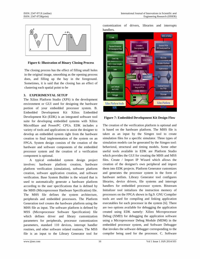
Figure 3: Illustration of Binary Opening Process
The whole procedure of opening can be interpreted as
“rolling the structuring element about the inside
boundary of the image”.
Figure 4: Binary Erosion Example
The effects of the opening process on the original
image are smoothing, reducing noise from quantization
or the sensor and pruning extraneous structures. These
effects result from the fact that the structuring element
cannot fit into the regions. Therefore, it can be said that
the result of the opening process heavily depends on
the shape of structuring elements. Fig.7 presents an
example of the opening process.
Figure 5: Binary Opening Example
The effects of the opening mentioned before are clearly
shown in the Figure 2.8. The vortices of the triangle
foreground have been cut out because the image is
“opened” with „square‟ type structuring element,
whereas those of the square are preserved.
2.3 BINARY CLOSING
Definitions: Binary Closing
Closing of a binary image A by a structuring element B,
denoted by A•B, is defined as
In the closing operation, dilation and erosion are applied
successively in that order. Note that this order is
reversed for the opening process.
In another aspect, the closing process on a binary image
can be defined as:
The closing operation can be described as in Fig.8, as
“rolling the structuring element on the outer boundary
of the image.”
ISSN: 2347-971X (online) International Journal of Innovations in Scientific and ISSN: 2347-9728(print) Engineering Research (IJISER)
www.ijiser.com 16 Vol 1 Issue 1 JAN 2014/103
Figure 6: Illustration of Binary Closing Process
The closing process has the effect of filling small holes
in the original image, smoothing as the opening process
does, and filling up the bay in the foreground.
Sometimes, it is said that the closing has an effect of
clustering each spatial point to be
3. EXPERIMENTAL SETUP
The Xilinx Platform Studio (XPS) is the development
environment or GUI used for designing the hardware
portion of your embedded processor system. B.
Embedded Development Kit Xilinx Embedded
Development Kit (EDK) is an integrated software tool
suite for developing embedded systems with Xilinx
MicroBlaze and PowerPC CPUs. EDK includes a
variety of tools and applications to assist the designer to
develop an embedded system right from the hardware
creation to final implementation of the system on an
FPGA. System design consists of the creation of the
hardware and software components of the embedded
processor system and the creation of a verification
component is optional.
A typical embedded system design project
involves: hardware platform creation, hardware
platform verification (simulation), software platform
creation, software application creation, and software
verification. Base System Builder is the wizard that is
used to automatically generate a hardware platform
according to the user specifications that is defmed by
the MHS (Microprocessor Hardware Specification) file.
The MHS file defines the system architecture,
peripherals and embedded processors. The Platform
Generation tool creates the hardware platform using the
MHS file as input. The software platform is defmed by
MSS (Microprocessor Software Specification) file
which defines driver and library customization
parameters for peripherals, processor customization
parameters, standard 110 devices, interrupt handler
routines, and other software related routines. The MSS
file is an input to the Library Generator tool for
customization of drivers, libraries and interrupts
handlers.
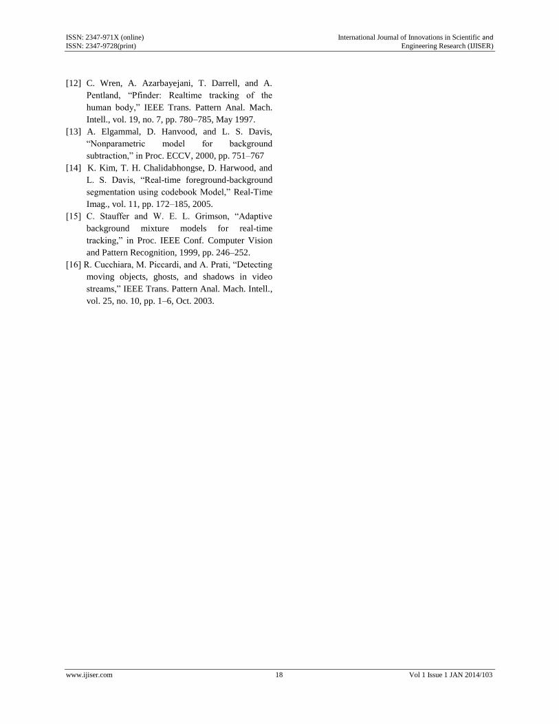
Figure 7: Embedded Development Kit Design Flow
The creation of the verification platform is optional and
is based on the hardware platform. The MHS file is
taken as an input by the Simgen tool to create
simulation files for a specific simulator. Three types of
simulation models can be generated by the Simgen tool:
behavioral, structural and timing models. Some other
useful tools available in EDK are Platform Studio
which provides the GUI for creating the MHS and MSS
files. Create / Import IP Wizard which allows the
creation of the designer's own peripheral and import
them into EDK projects. Platform Generator customizes
and generates the processor system in the form of
hardware netlists. Library Generator tool configures
libraries, device drivers, file systems and interrupt
handlers for embedded processor system. Bitstream
Initializer tool initializes the instruction memory of
processors on the FPGA shown in fig.9. GNU Compiler
tools are used for compiling and linking application
executables for each processor in the system [6]. There
are two options available for debugging the application
created using EDK namely: Xilinx Microprocessor
Debug (XMD) for debugging the application software
using a Microprocessor Debug Module (MDM) in the
embedded processor system, and Software Debugger
that invokes the software debugger corresponding to the
compiler being used for the processor. C. Software

ISSN: 2347-971X (online) International Journal of Innovations in Scientific and ISSN: 2347-9728(print) Engineering Research (IJISER)
www.ijiser.com 17 Vol 1 Issue 1 JAN 2014/103
Development Kit Xilinx Platform Studio Software
Development Kit (SDK) is an integrated development
environment, complimentary to XPS, that is used for
C/C++ embedded software application creation and
verification. SDK is built on the Eclipse open source
framework. Soft Development Kit (SDK) is a suite of
tools that enables you to design a software application
for selected Soft IP Cores in the Xilinx Embedded
Development Kit (EDK).The software application can
be written in a "C or C++" then the complete embedded
processor system for user application will be completed,
else debug & download the bit file into FPGA. Then
FPGA behaves like processor implemented on it in a
Xilinx Field Programmable Gate Array (FPGA) device.
4. TABULATION RESULT
The Algorithm is implemented in Micro blaze
Processor and the results are furnished in the tabulation
below
5. CONCLUSION
The proposed method is inherently parallel, since
computations for each pixel of each sequence frame
can be done concurrently with no need for
communications. This can help in lowering execution
times for high-resolution sequences. Moreover, the
approach is suitable to be adopted in a layered
framework, where, operating at region-level, it can
improve detection results allowing to more efficiently
tackle the camouflage problem and to distinguish
morphological Image by the morphological operator.
This is a very desirable operative mode, considering
that a very actual visual segmentation with high
accuracy is achieved.
REFERENCES
[1] K. Toyama, J. Krumm, B. Brumitt, and B. Meyers,
“Wallflower: principles and practice of
background maintenance,” in Proc. 7th IEEE
Conf. Computer Vision, 1999, vol. 1, pp. 255–
261.
[2] G. Backer, B. Mertsching, and M. Bollmann,
“Data- and model-driven gaze control for an
active-vision system,” IEEE Trans. Pattern Anal
[3] G.L.Foresti,”A Real Time System for Video
Surveillance of Unattended Outdoor
Environments”.
[4] J. M. Ferryman, Ed., in Proc. 9th IEEE Int.
Workshop on Performance Evaluation of Tracking
and Surveillance, 2006.
[5] R. T. Collins, A. J. Lipton, T. Kanade, H. Fujiyoshi,
D. Duggins, Y. Tsin, D. Tolliver, N. Enomoto, O.
Hasegawa, P. Burt, and L. Wixson, “A system for
video surveillance and monitoring,” Tech. Rep.
CMU-RI-TR-00-12, The Robotics Inst., Carnegie
Mellon Univ., Pittsburgh, PA, 2000.
[6] J. L. Barron, D. J. Fleet, and S. S. Beauchemin,
“Performance of optical flow techniques,” Int. J.
Comput. Vis., vol. 12, no. 1, pp. 42–77, 1994.
[7] L. Maddalena and A. Petrosino, “A self-organizing
approach to detection of moving patterns for real-
time applications,” in Proc. 2nd Int. Symp. Brain,
Vision, and Artificial Intelligence, 2007, pp. 181–
190, Lecture Notes Comput. Sci. 4729.
[8] S.-C. Cheung and C. Kamath, “Robust techniques
for background subtraction in urban traffic video,”
in Proc. EI-VCIP, 2004, pp. 881–892.
[9] M. Piccardi, “Background subtraction techniques:
are view,” in Proc.IEEE Int. Conf. Systems, Man,
Cybernetics, 2004, pp. 3099–3104.
[10] B. P. L. Lo and S. A. Velastin, “Automatic
congestion detection system for underground
platforms,” in Proc. ISIMP, 2001, pp. 158–161.
[11] R. J. Radke, S. Andra, O. Al-Kofahi, and B.
Roysam, “Image change detection algorithms: a
systematic survey,” IEEE Trans. Image Process.,
vol. 14, no. 3, pp. 294–307, Mar. 2005.
ISSN: 2347-971X (online) International Journal of Innovations in Scientific and ISSN: 2347-9728(print) Engineering Research (IJISER)
www.ijiser.com 18 Vol 1 Issue 1 JAN 2014/103
[12] C. Wren, A. Azarbayejani, T. Darrell, and A.
Pentland, “Pfinder: Realtime tracking of the
human body,” IEEE Trans. Pattern Anal. Mach.
Intell., vol. 19, no. 7, pp. 780–785, May 1997.
[13] A. Elgammal, D. Hanvood, and L. S. Davis,
“Nonparametric model for background
subtraction,” in Proc. ECCV, 2000, pp. 751–767
[14] K. Kim, T. H. Chalidabhongse, D. Harwood, and
L. S. Davis, “Real-time foreground-background
segmentation using codebook Model,” Real-Time
Imag., vol. 11, pp. 172–185, 2005.
[15] C. Stauffer and W. E. L. Grimson, “Adaptive
background mixture models for real-time
tracking,” in Proc. IEEE Conf. Computer Vision
and Pattern Recognition, 1999, pp. 246–252.
[16] R. Cucchiara, M. Piccardi, and A. Prati, “Detecting
moving objects, ghosts, and shadows in video
streams,” IEEE Trans. Pattern Anal. Mach. Intell.,
vol. 25, no. 10, pp. 1–6, Oct. 2003.