Gravity Sewer Design - PDHonline.com · Gravity Sewer Design Jorge E. Acevedo, P.E. 1. Introduction...
49
An Approved Continuing Education Provider PDH Course C606 (8 PDH) Gravity Sewer Design Jorge E. Acevedo, P.E. 2012 PDH Online | PDH Center 5272 Meadow Estates Drive Fairfax, VA 22030-6658 Phone & Fax: 703-988-0088 www.PDHonline.org www.PDHcenter.com
Transcript of Gravity Sewer Design - PDHonline.com · Gravity Sewer Design Jorge E. Acevedo, P.E. 1. Introduction...

An Approved Continuing Education Provider
PDH Course C606 (8 PDH)
Gravity Sewer Design
Jorge E. Acevedo, P.E.
2012
PDH Online | PDH Center
5272 Meadow Estates Drive Fairfax, VA 22030-6658
Phone & Fax: 703-988-0088 www.PDHonline.org www.PDHcenter.com

www.PDHcenter.com PDHonline Course C606 www.PDHonline.org
©2012 Jorge E. Acevedo Page 2 of 49
Gravity Sewer Design
Jorge E. Acevedo, P.E.
1. Introduction This course provides standards, policy, and procedures for the hydraulic design of sanitary gravity sewer systems based on rules and regulations in the State of Florida including specific regulations within the Miami-Dade County. Standards for design and preparation for plans and specifications for wastewater facilities have been published by the Committee of the Great Lakes – Upper Mississippi River Board of State and Provincial Public Health and Environmental Managers. These standards, known as Ten State Standards and referred as Recommended Standards for Wastewater Facilities (RSWF), are guideline policies for the design, review, and approval of plans and specifications for wastewater collection and treatment facilities. Specification for the design, materials, and installation requirements of the gravity sanitary sewer system has been published by many utilities, cities, counties, and states nationwide; each publication has been developed according to a set of particular conditions, rules and regulations specifically for each study area. The State of Florida Statutes at Section 403.051(2)(a) mandates that any Department planning, design, construction, modification or operating standards, criteria, and requirements for wastewater collection/transmission be developed; the intent of the Florida Rule 62-400 is promulgated to implement the provisions and requirements of mentioned section of the Florida Statutes as well other sections concerning wastewater collection and transmission systems. The purpose of Chapter 62-604, Florida Administrative Code (F.A.C.), is to provide minimum design and operation and maintenance standards for domestic wastewater collection/transmission systems. Systems shall be designed in accordance with sound engineering practice. Supported by moderating provisions, it is intended that Chapter 62-604, F.A.C., establish a framework whereby design

www.PDHcenter.com PDHonline Course C606 www.PDHonline.org
©2012 Jorge E. Acevedo Page 3 of 49
flexibility and sound engineering practice can be used in developing systems with which to collect and transport domestic wastewater in an environmentally sound manner. As appropriate, Chapter 62-604, F.A.C. shall be used in conjunction with other State rules relating to the design and operation and maintenance of domestic wastewater collection/transmission systems. Requirements in this State rule shall apply to both public and private domestic wastewater collection/transmission systems. The technical standards and criteria contained in the RSWF as well as others listed standard manuals and technical publications of this State rule are hereby incorporated by reference and shall be applied, if applicable, in determining whether permits allowing construction or modification of collection/transmission systems shall be issued or denied. In cases where the standards and criteria contained in the publications listed in the State rule conflict, the standards and criteria contained in the RSWF shall be used. Compliance with the State Rules and Regulations, in Miami-Dade County, gravity sanitary sewer systems shall be designed in accordance with the minimum standards for design and construction published by Miami Dade Water and Sewer Department (MD-WASD), which are based on the State of Florida Department of Environmental Protection (FDEP) Rules, Chapter 62-604 F.A.C. for wastewater facilities, with the Occupational Safety and Health Administration (OSHA) requirements and with the Florida State Board Health Sewage Guide and the recommendations of Chapter 12 of the American Society of Civil Engineer (ASCE) Manual No. 37, Sewer Design and Construction. MD-WASD, one of the fourth largest water and wastewater utilities in the United States, published and revises annually the Design and Construction Standard Specifications and Details as minimum standards pertaining to the design, construction, materials and installation of public and private sewer system within the Miami-Dade County. In addition, sanitary sewer systems to be constructed and in service within the Miami-Dade County shall be designed and installed in accordance with the requirements of the South Florida Building Code and the Miami-Dade Code of

www.PDHcenter.com PDHonline Course C606 www.PDHonline.org
©2012 Jorge E. Acevedo Page 4 of 49
Ordinance Chapter 24 which is managed by Miami-Dade Regulatory and Economic Resources (MD-RER), previously known as the Miami-Dade Department of Environmental Resources Management (MD-DERM). The intent of this course is provide broad guidelines for the design and construction of sanitary sewer gravity lines based on all, the MD-RER regulations, the MD-WASD specifications, the State of Florida Rules and Regulations, and the RSWF; however, this course does not intend to cover all material or installation procedures which may be required by any regulatory agency neither warranty the approval of any required permit application. This course also provides guidelines for population projection, flow calculation, engineering hydraulic design and calculations, material selection and structural design, and general information for installation and testing of gravity sanitary sewer systems. 2. Gravity Sanitary Sewer System Gravity sanitary sewer systems are a collection of underground pipes or drains used primarily to convey wastewater from a community to an authorized point of discharge such as a lift station, pump station or a wastewater treatment facility. A gravity sanitary sewer system transports wastewater mainly by gravity along a downward-sloping pipe and it should be designed based on the pipe size and slope to maintain adequate flow towards the discharge point without surcharging manholes or pressurizing the system. Miami-Dade County sanitary sewer collection system consists of gravity systems that convey wastewater for more than one thousand basin areas to lift stations and pump stations which discharge into one of the three wastewater treatment facilities. There are publicly and privately owned or operated sanitary sewer collection systems in the County and all of them are regulated by MD-RER under the Miami-Dade County Code Chapter 24 and the Florida Statute under Chapter 62-604. In the Miami-Dade County the majority of the publicly own sanitary sewer systems are operated and maintained by MD-WASD. There are also some
www.PDHcenter.com PDHonline Course C606 www.PDHonline.org
©2012 Jorge E. Acevedo Page 5 of 49
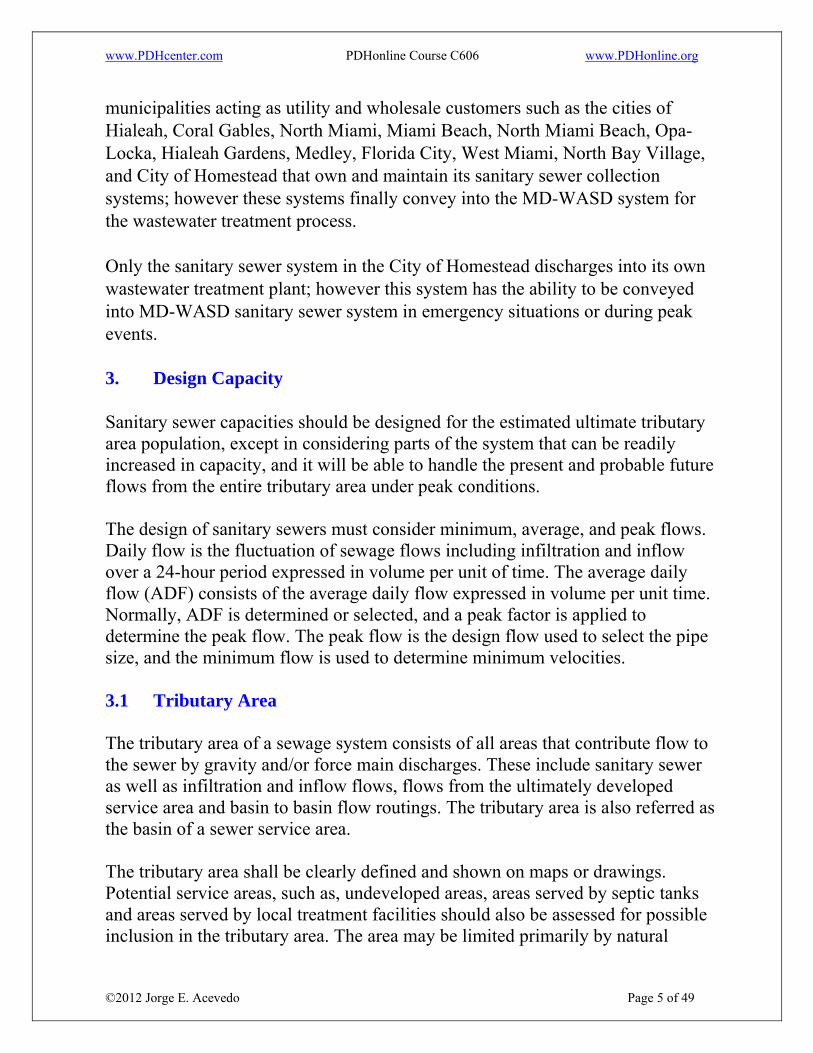
municipalities acting as utility and wholesale customers such as the cities of Hialeah, Coral Gables, North Miami, Miami Beach, North Miami Beach, Opa-Locka, Hialeah Gardens, Medley, Florida City, West Miami, North Bay Village, and City of Homestead that own and maintain its sanitary sewer collection systems; however these systems finally convey into the MD-WASD system for the wastewater treatment process. Only the sanitary sewer system in the City of Homestead discharges into its own wastewater treatment plant; however this system has the ability to be conveyed into MD-WASD sanitary sewer system in emergency situations or during peak events. 3. Design Capacity Sanitary sewer capacities should be designed for the estimated ultimate tributary area population, except in considering parts of the system that can be readily increased in capacity, and it will be able to handle the present and probable future flows from the entire tributary area under peak conditions. The design of sanitary sewers must consider minimum, average, and peak flows. Daily flow is the fluctuation of sewage flows including infiltration and inflow over a 24-hour period expressed in volume per unit of time. The average daily flow (ADF) consists of the average daily flow expressed in volume per unit time. Normally, ADF is determined or selected, and a peak factor is applied to determine the peak flow. The peak flow is the design flow used to select the pipe size, and the minimum flow is used to determine minimum velocities. 3.1 Tributary Area The tributary area of a sewage system consists of all areas that contribute flow to the sewer by gravity and/or force main discharges. These include sanitary sewer as well as infiltration and inflow flows, flows from the ultimately developed service area and basin to basin flow routings. The tributary area is also referred as the basin of a sewer service area. The tributary area shall be clearly defined and shown on maps or drawings. Potential service areas, such as, undeveloped areas, areas served by septic tanks and areas served by local treatment facilities should also be assessed for possible inclusion in the tributary area. The area may be limited primarily by natural

www.PDHcenter.com PDHonline Course C606 www.PDHonline.org
©2012 Jorge E. Acevedo Page 6 of 49
topography, natural or human-made barriers, or by political boundaries or economic factors. The design engineer should research the existing sewer to which a connection is being made; as-built drawings and sewer maps or atlas should be reviewed to help define the tributary area boundary. Although these records may not be actualized, sewer maps and drainage maps may be helpful in determining the tributary area. Proposed new tributary areas and/or any changes to the current areas may require approval by the authorized agency and water and sewer utility. 3.2 Design Period. Once the tributary area has been determined, the design period needs to be established. Design period is that length of time the capacity of the sewerage facility is anticipated to be adequate to service its tributary area. It must be determined prior to the design of the facility. The service life, defined as the operational life of a sewage facility, should exceed the design period of the facility, provided it is designed, constructed and maintained properly. Laterals and mains less than 18-inch in diameter shall be designed for estimated ultimate development or at least 100 years. The design of mains, trunks, interceptors and outfalls shall take into consideration a reasonable planning period between 50 - 100 years and cost effectiveness. For large sanitary sewer, historic trends and projections in population, water use, and wastewater flows must be studied prior to selecting a design period. When the project does not provide for the ultimate capacity, a report detailing a plan for providing the ultimate capacity shall be developed. United States Environmental Protection Agency, USEPA cost-effectiveness guidelines recommend a useful life of 50 years for wastewater conveyance structures including collection systems. 3.3 Design Average Flow The design average flow is the average of the daily volumes to be received for a continuous 12 month period expressed as a volume per unit time. It may be

www.PDHcenter.com PDHonline Course C606 www.PDHonline.org
©2012 Jorge E. Acevedo Page 7 of 49
expressed as Annual Average Daily Flow (AADF). However, the design average flow for facilities having critical seasonal high hydraulic loading periods such as recreational areas, school campuses, and industrial facilities shall be based on the daily average flow during the seasonal period. 4. Wastewater Flow Calculations There is no one unique and correct approach to the projection and calculation of sanitary sewer flows within a service area because each service area has its own unique characteristics. The design engineer is encouraged to use his own initiative and judgment for the projection of flows in conjunction with all current studies, rules and regulations. If this information has not been developed or is not available, other parameters shall be evaluated to project wastewater flows and they should be particular for each area or region. 4.1 Parameters for Flow Evaluation The following parameters shall be evaluated to project wastewater flows: 4.1.1 Population Estimate Because the flow is largely a function of population served, the population estimate for the tributary area is the basis for computing the design flow. It is customary to multiply the estimated population by the estimated per capita wastewater contribution. Present and predicted population shall be based on a 20 year planning period. Sewer and other facilities with a design life in excess of 20 years should be designed for the extended period. Care should be exercised where season or transient population are included. Population data is available at the U.S. Census Bureau, which provides population and housing data every ten years. The last U.S Census occurred during 2010 and the data is available at http://2010.census.gov/2010census/data/ Census tract (CT) is a defined area boundary developed for census purposes. Every CT provides population and employment projections. Each sewage
www.PDHcenter.com PDHonline Course C606 www.PDHonline.org
©2012 Jorge E. Acevedo Page 8 of 49
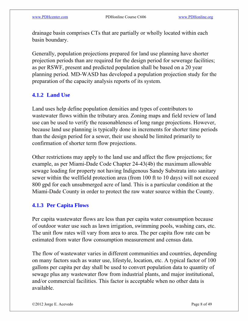
drainage basin comprises CTs that are partially or wholly located within each basin boundary. Generally, population projections prepared for land use planning have shorter projection periods than are required for the design period for sewerage facilities; as per RSWF, present and predicted population shall be based on a 20 year planning period. MD-WASD has developed a population projection study for the preparation of the capacity analysis reports of its system. 4.1.2 Land Use Land uses help define population densities and types of contributors to wastewater flows within the tributary area. Zoning maps and field review of land use can be used to verify the reasonableness of long range projections. However, because land use planning is typically done in increments for shorter time periods than the design period for a sewer, their use should be limited primarily to confirmation of shorter term flow projections. Other restrictions may apply to the land use and affect the flow projections; for example, as per Miami-Dade Code Chapter 24-43(4b) the maximum allowable sewage loading for property not having Indigenous Sandy Substrata into sanitary sewer within the wellfield protection area (from 100 ft to 10 days) will not exceed 800 gpd for each unsubmerged acre of land. This is a particular condition at the Miami-Dade County in order to protect the raw water source within the County. 4.1.3 Per Capita Flows Per capita wastewater flows are less than per capita water consumption because of outdoor water use such as lawn irrigation, swimming pools, washing cars, etc. The unit flow rates will vary from area to area. The per capita flow rate can be estimated from water flow consumption measurement and census data. The flow of wastewater varies in different communities and countries, depending on many factors such as water use, lifestyle, location, etc. A typical factor of 100 gallons per capita per day shall be used to convert population data to quantity of sewage plus any wastewater flow from industrial plants, and major institutional, and/or commercial facilities. This factor is acceptable when no other data is available.

www.PDHcenter.com PDHonline Course C606 www.PDHonline.org
©2012 Jorge E. Acevedo Page 9 of 49
4.1.4 Residential Flows Residential flows may generally be counted for multiplying the resident population times the per capita wastewater flow. A typical value of 100 gallons per capita has been used but other considerations may be affected such season occupancy and unit sizes. 4.1.5 Commercial Flows Commercial flows may generally be accounted for by multiplying the employment population times the estimated employee wastewater flow. A typical value of 30 gallons per employee per day has been used but commercial operations which may contribute significantly greater flows, such as, car washes, laundry facilities, etc., shall be investigated and considered. 4.1.6 Industrial Flows Industrial wastewater flows may vary significantly depending on the industry type, size, operational techniques and whether or not the industry has onsite treatment of wastewater. Also, peak flows may be significant because of the method of operation and work shifts. If significant industries are in the project area, it shall be necessary for the design engineer to conduct a survey to determine the magnitude of contribution from the various industries. 4.1.7 Infiltration / Inflow Groundwater Infiltration (GWI), also referred as Infiltration, is the total groundwater flow entering into the pipeline and maintenance hole defects, because of poor construction, corrosion of the pipes, structural failure through the joints, porous walls or brakes. Drainage or rainfall runoff that enters the collection system through direct illegal or permitted connections, such as cross connections, catch basins, downspouts, area drains and manhole covers is referred as inflow or storm water inflow. Inflow is separated and distinguished from infiltration.

www.PDHcenter.com PDHonline Course C606 www.PDHonline.org
©2012 Jorge E. Acevedo Page 10 of 49
Design capacity shall include an allowance for extraneous flows which inevitably become a part of the total flow. These flows include GWI and inflow and are commonly known as infiltration/Inflow (I/I) flows. Studies have shown that the I/I flows component in some cities are generally insignificant and may be accounted for by using conservative per capita flows. However, other areas, such as Miami-Dade County, have shown that I/I flows component are very significant to the total flow; if flow monitoring determines that significant I/I flows are present in the tributary area, the design engineer shall account for that additional component of flow. As per Miami-Dade Code Chapter 24.42.2(1)(d), the I/I into the existing sanitary sewer collection system shall be less than 5,000 gallons per inch pipe diameter per day per mile of pipe and laterals. 4.2 Flow Projection Studies Many counties and cities have developed their own studies to determine the flow projection based on land use, zoning codes, and census population. Miami-Dade Code Chapter 24-43, Protection of public potable water supply wells, intent and purpose is to safeguard the public health, safety and welfare by providing scientifically established standards for land uses within the cones of influence thereby protecting public potable water supply wells from contamination. Miami-Dade County has developed and implemented a sewage flow study and it has been adapted into Miami-Dade Code under the Section 24-43.1(5) which presents a table used by the Director or Director’s Designee of the Department to determine sewage flows for sanitary sewers and the maximum allowable septic tank sewage loading requirements. This table provides estimated flows based on proposed building areas or service units; it subdivides the uses base on the type of zoning land use: Residential, Commercial and industrial. This table last updated on December 2010. For example, in a residential zone a proposed 3,500 square feet (sq ft) single family residence will load 320 gallons per day (gpd)/per unit based on size 3000-5000 sq ft; in a commercial area, a proposed 5,000 sq ft full service restaurant will load 5,000 gpd based on a 1 gpd per sq ft with a minimum of 350 gpd, in an industrial area a proposed total 45,000 sq ft warehouse with 5,000 sq ft of dry

www.PDHcenter.com PDHonline Course C606 www.PDHonline.org
©2012 Jorge E. Acevedo Page 11 of 49
manufacturing use will load 525 gpd based on 1 gpd/100 sq ft of warehouse and 2.5 gpd/100 sq ft of industrial use. Table 1 presents the complete flows determined by the Miami-Dade Code Chapter 24. Table 1. Estimate Sewage Loading (from Miami-Dade Chapter 24.43) Types of Land Uses Gallons per Day (gpd) _____ _____
Residential Land Uses Single Family Residence 220 gpd / unit (under 3001 sq ft)
320 gpd / unit ( 3001- 5000 sq ft) 550 gpd / unit (over 5000 sq ft)
Apartments 150 gpd / unit Condo 150 gpd / unit Duplex 360 gpd-180 gpd / unit Mobile Homes 180 gpd / unit Townhouse 180 gpd / unit Trailers / Camper/ RV, seasonal use 150 gpd / space Triplex 540 gpd- 180 gpd / unit Twin Home 360 gpd-180 gpd / unit Assistance Living Facility <6 Beds 75 gpd / bed
Commercial Land Uses Amusement Center/Arcade (Based on Retail rating) 10 gpd / 100 sq ft With food preparation, use restaurant chart Art Gallery/Studio (Based on Retail rating) 10 gpd / 100 sq ft Bakeries 35 gpd / 100 sq ft Banquet Hall 15 gpd / 100 sq ft
With kitchen 50 gpd / 100 sq ft Bar and Cocktail Lounge 20 gpd / 100 sq ft Barber Shop 15 gpd / 100 sq ft Beauty Shop (including: manicure, pedicure, and Unisex salon)
25 gpd / 100 sq ft Bible Study/Sunday School (Based on House of Worship) 10 gpd / 100 sq ft

www.PDHcenter.com PDHonline Course C606 www.PDHonline.org
©2012 Jorge E. Acevedo Page 12 of 49
Bingo Hall 10 gpd / 100 sq ft Book Store 10 gpd / 100 sq ft With coffee shop area only 50 gpd / 100 sq ft Bowling Alley 100 gpd / lane Car Dealership 5 gpd / 100 sq ft
With showroom and offices 5 gpd / 100 sq ft Repair Shop 10 gpd / 100 sq ft Car Wash, use Car Wash rating
Car Wash Hand Type 350 gpd / bay Automated 5500 gpd / bay Recycle Allocation Letter
Casinos (Based on retail rating) 10 gpd / 100 sq ft Check Cashing Store
(Based on retail rating) 10 gpd / 100 sq ft Clinics (Urgent Care, Health School) 20 gpd / 100 sq ft Coin Laundry 145 gpd / washer Computer Repair Shops 10 gpd / 100 sq ft Community Center 10 gpd / 100 sq ft Congregate Living Facility 75 gpd / bed Construction Temp Trailers 5 gpd / 100 sq ft Country Club 15 gpd / 100 sq ft
With kitchen 50 gpd / 100 sq ft Dentist’s Office 20 gpd / 100 sq ft Dry Cleaners (no machines) 10 gpd / 100 sq ft
(with machines see Laundry chart) Dorm based on other 100 gpd / bed Fire Station 100 gpd / bed Food Preparation
(Meat Markets, Commissaries) 35 gpd / 100 sq ft Funeral Homes 10 gpd / 100 sq ft Gas Station-Convenience Store
(pumps, sales, coffee, and repair shop) 450 gpd With automated drive through car wash 1750 gpd / bay Additional automatic car wash bay 1300 gpd / bay
Other vendors, see chart) Guard House / Bridge House 60 gpd / unit Gym (including showers) 10 gpd / 100 sq ft Hospitals 250 gpd / bed
(all beds, bazenettes, cafeteria, rehab, gyms, hospitalist)

www.PDHcenter.com PDHonline Course C606 www.PDHonline.org
©2012 Jorge E. Acevedo Page 13 of 49
House of Worship including pews 10 gpd / 100 sq ft Hotel or Motel 100 gpd / room
Gym w or w/showers 10 gpd / 100 sq ft Spa (open to public) 25 gpd / 100 sq ft Restaurants (see Rest chart) Cabanas no charge
w/ any type of plumbing 100 gpd / unit Soccer Field 3 gpd / seat Jail 150 gpd / bed Juice Bar 50 gpd / 100 sq ft
No food 20 gpd / 100 sq ft Kennels 15 gpd / cage Lab 10 gpd / 100 sq ft Laundry
Coin Laundry 145 gpd / unit Industrial Allocation Letter
Library 10 gpd / 100 sq ft Marinas 60 gpd / slip Meeting Room (Based on retail) 10 gpd / 100 sq ft Motor Vehicle Service Station
stand alone 10 gpd / 100 sq ft Museum 10 gpd / 100 sq ft Nursing/Convalescent Home
(Full time staff) 150 gpd / bed Office Space (including Banks) 5 gpd / 100 sq ft Pet Grooming 55 gpd / 100 sq ft Pet Shop Retail 10 gpd / 100 sq ft Pet Grooming 55 gpd / 100 sq ft
Overnight Stay 15 gpd /cage Veterinarian 20 gpd / 100 sq ft
Physician’s Office 20 gpd / 100 sq ft (MD’s or DO’s but not limited to: Dentist, Chiropractor, Psychiatrist, Psychologist, Optometrist, Acupuncturist, Ophthalmologist, and Veterinarian, Podiatrist, and Therapist)
Pool Hall 10 gpd / 100 sq ft With kitchen 50 gpd / 100 sq ft
Public Parks with toilets only 5 gpd / person with toilets and showers 20 gpd / person
Public Swimming Pool 30 gpd / person

www.PDHcenter.com PDHonline Course C606 www.PDHonline.org
©2012 Jorge E. Acevedo Page 14 of 49
Restaurants Full Service 100 gpd / 100 sq ft
(waitress with non disposable Silverware) Fast Food 50 gpd / 100 sq ft
(no waitress disposable silverware) Take Out (no seats) 100 gpd / 100 sq ft Bar/Lounge 20 gpd / 100 sq ft Bakeries 35 gpd / 100 sq ft
(Commercial wholesale) Bakeries 100 gpd / 100 sq ft
(Take out only rated at take out) Bakeries 50 gpd / 100 sq ft
(w/seats rated at fast food) Juice Bar 50 gpd / 100 sq ft Juice Bar no food 20 gpd / 100 sq ft) Ball Room (banquet hall) 15 gpd / 100 sq ft Party Center (Dandy Bear) 50 gpd / 100 sq ft Coffee Shop 50 gpd / 100 sq ft (Starbucks rated at fast food) Night Clubs/Lounge 20 gpd / 100 sq ft
(rated at bar/lounge) Retail Centers 10 gpd / 100 sq ft
(including: deli, meat market, food prep, and storage or with same cashier as retail)
Sales Trailer 5 gpd / 100 sq ft Schools (including: Staff, Cafeteria, and showers)
Regular School 12 gpd / 100 sq ft Day Care/Nursery 20 gpd / 100 sq ft Ballet School 10 gpd / 100 sq ft Beauty School 25 gpd / 100 sq ft
(Based on Beauty Shop) Karate School 10 gpd / 100 sq ft Tutoring Center 10 gpd / 100 sq ft Yoga 10 gpd / 100 sq ft
Spa (Massage) 25 gpd / 100 sq ft Stadium, Racetrack, Ballpark, Fronton, Auditorium 3 gpd / seat Tanning Salon (Based on retail rating) 10 gpd / 100 sq ft Tattoo Parlor (Based on retail rating) 10 gpd / 100 sq ft Television Studio 10 gpd / 100 sq ft Tennis Club 15 gpd / 100 sq ft

www.PDHcenter.com PDHonline Course C606 www.PDHonline.org
©2012 Jorge E. Acevedo Page 15 of 49
Theater (Cobb) Indoor 3 gpd / seat Outdoor 5 gpd / space Cine Bistro 3 gpd / seat
(food are) +100 gpd / 100 sq ft Veterinarian Office 20 gpd / 100 sq ft Wax Salon (Based on retail rating) 10 gpd / 100 sq ft
Industrial Land Use Airports
Concourse 5 gpd / 100 sq ft Retail 10 gpd / 100 sq ft Airplane Repair 10 gpd / 100 sq ft Hangar 1 gpd / 100 sq ft
Food Service use restaurant chart Industrial Use Dry Use (MANUFACTURING)
(Cabinet Makers, Shutters, Assembling, Repair, Factory, Painting, Welding, Carpentry, Processing, Machine Shop, Paint & Body Shop, Printing) 2.5 gpd / 100 sq ft
Industrial Use Wet Use (Granite Manufacturing, Platting, Silk Screening)
20 gpd / 100 sq ft Mini Storage 1.5 gpd / 100 sq ft Warehouse (Storage) 1 gpd / 100 sq ft
5. Hydraulic Design The criteria for hydraulic design sewer pipe is evaluated based on the size and type of the pipe, design period, design depth and peak flows. 5.1 Hydraulic Types of Flows The flow of wastewater in sewers may be classified as open channel or pressure flow. When flow fills the conduit and the Hydraulic Grade Line (HGL) rises above the sewer crown, the flow is classified as pressure flow. When the conduit is partially full and the HGL is below the sewer crown and a freewater surface develops in the sewer, the flow is classified as an open channel flow.

www.PDHcenter.com PDHonline Course C606 www.PDHonline.org
©2012 Jorge E. Acevedo Page 16 of 49
The hydraulic slope (S) in open channels is considered as the slope of the channel bottom, or longitudinal slope. S is normally determined by the natural slope of the site being drained. Open channel flow will be the basis for general hydraulic design of gravity sanitary sewers systems. The types of open channel flows which may be found in sanitary sewers are steady flow, unsteady flow, uniform flow, non-uniform flow, steady uniform flow, unsteady uniform flow, steady non-uniform flow and unsteady non-uniform flow. Steady flow occurs when the depth of flow is constant with respect to time. Unsteady flow occurs when the depth of flow is not constant with respect to time. Uniform flow occurs when the depth of flow does not change with respect to location. Non-uniform flow occurs when the depth of flow changes with respect to location. Steady uniform flow occurs when in a given stretch of a sewer pipe, having a constant shape, size, slope and interior roughness, a constant rate of flow enters the upstream end of the pipe and the same exits at the downstream end of the pipe. In this flow regime, the depth of flow is constant with respect to time and location and the HGL is parallel to the sewer invert slope. Unsteady uniform flow occurs when the HGL remains parallel to the sewer invert and fluctuates up and down as the rate of flow fluctuates with time. This type of flow is not very common in sewer design. Steady non-uniform flow shall be considered when different constant rates of flow enter a sewer along its length at various locations. However, a simplification of this case is used in the design of such sewers. Accordingly, the sum of all the flows for a given stretch of the sewer is assumed to enter the pipe at its upstream end, thereby reducing the flow regime to a steady uniform case. Unsteady non-uniform flow develops during the onset and termination of peak flows. However, design of sewers based on this flow regime is seldom required, as it involves extensive calculations for flow routing, wave and water surface profiles.

www.PDHcenter.com PDHonline Course C606 www.PDHonline.org
©2012 Jorge E. Acevedo Page 17 of 49
In general, the design of gravity sanitary sewers systems shall be based on steady uniform flow analysis employing the Manning equation. 5.2 Manning Equation The Manning equation or formula, also known as the Gauckler-Manning formula is an empirical formula for open channel flow or free-surface driven by gravity. It was first presented by Philippe Gauckler in 1867 and re-developed by Robert Manning in 1890. It states:
V= Q/A=k/n Rh(2⁄3) S(1⁄2) (1)
Where: V = cross sectional average velocity (ft/s); flow/ Area, Q/A (ft3/s/ft2) k = conversion factor of 1.486 for US customary units n = Manning’s roughness coefficient Rh = Hydraulic radius (ft,) S = Slope of the water surface or the linear hydraulic head loss, hf/L (ft/ft).
Manning’s roughness coefficient, often denoted as n, is an empirically derived coefficient, which is dependent on many factors, including surface roughness and sinuosity. A value of 0.014 is used for sizing gravity sewer. However a value of 0.013 is referred by RSFW. This coefficient shall be used regardless of the type of pipe specified. 5.3 Minimum Slope and Velocity Minimum flows are used to determine if specified velocities can be maintained to prevent deposition of solids. Slope is the key criterion in designing sewer collection systems to avoid odor and corrosion problems due to sulfides in wastewater. Sewer systems designed with long runs at minimum slopes are prone to sulfide generation due to long residence times, poor oxygen transfer, and deposition of solids. Sewer system design is based on achieving self-cleaning velocities during normal daily peak flow periods to transport any grit which may enter the sewer system,
www.PDHcenter.com PDHonline Course C606 www.PDHonline.org
©2012 Jorge E. Acevedo Page 18 of 49
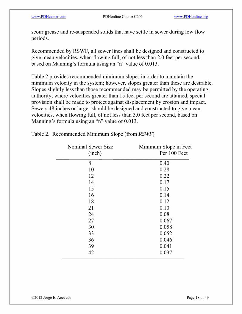
scour grease and re-suspended solids that have settle in sewer during low flow periods. Recommended by RSWF, all sewer lines shall be designed and constructed to give mean velocities, when flowing full, of not less than 2.0 feet per second, based on Manning’s formula using an “n” value of 0.013. Table 2 provides recommended minimum slopes in order to maintain the minimum velocity in the system; however, slopes greater than these are desirable. Slopes slightly less than those recommended may be permitted by the operating authority; where velocities greater than 15 feet per second are attained, special provision shall be made to protect against displacement by erosion and impact. Sewers 48 inches or larger should be designed and constructed to give mean velocities, when flowing full, of not less than 3.0 feet per second, based on Manning’s formula using an “n” value of 0.013. Table 2. Recommended Minimum Slope (from RSWF)
Nominal Sewer Size Minimum Slope in Feet (inch) Per 100 Feet
________ __ ________________________________________________
8 0.40 10 0.28 12 0.22 14 0.17 15 0.15 16 0.14 18 0.12 21 0.10 24 0.08 27 0.067 30 0.058 33 0.052 36 0.046 39 0.041 42 0.037
_____________________________________________________________________________

www.PDHcenter.com PDHonline Course C606 www.PDHonline.org
©2012 Jorge E. Acevedo Page 19 of 49
5.4 Minimum Pipe Size Manning’s equation is also used to determine the pipe size. For gravity sanitary sewer a minimum 8-inch pipe diameter is recommended by RSWF and it has been implemented by many utilities including Miami-Dade County. 5.5 Peak Flows and Peak Factors The flow of wastewater will vary continuously throughout day to day; the I/I component may remain constant throughout day to day except during a raining period. The ratio of the peak flow to the average for the day will range from less than 130% for some large sanitary sewer to 200% for smaller sanitary sewers. Peak Factor is the ratio of peak hourly flow and ADF. Design Maximum Day Flow, also referred as daily peak flow, is the largest volume of sewage flow to be received during a continuous 24-hour period expressed as volume per unit time. Design peak hourly flow is the largest volume of sewage flow to be received during a one-hour period expressed as a volume per unit time. Design peak instantaneous flow is the instantaneous maximum flow rate to be received expressed as volume per unit time. The RSFW provides the typical design average flow calculation, which is based as the design peak hourly flow by the population factor. The population factor is expressed as:
Q(Peak Hourly)/Q(Design Average) = (18+ √P)/(4+ √P) (2) Where:
Q is the flow, and P is the population in thousand.
www.PDHcenter.com PDHonline Course C606 www.PDHonline.org
©2012 Jorge E. Acevedo Page 20 of 49
6. Structural Design 6.1 Layout of the System
The design engineer begins a sanitary sewer system layout by selecting an outlet, determining the tributary area, locating trunk and main sewer lines and determining the need for and location of pumping station and force mains. Preliminary layout can be made largely from topographic maps and other preliminary information; in general sanitary sewer systems will have a gradient in the same direction as street or ground surfaces and will be connected by trunk or main sewers. In the Miami-Dade area where the gradient of the ground is null the direction of the flow will be forward to the outlet or point of discharge. This point of discharge is located according to the circumstances of the particular project. Thus, a system may discharge to a treatment plant, a pumping station, or a main sanitary sewer. The most common location of sanitary sewer is at or near the center of street or alley. A single sanitary sewer then serves both sides of the street with approximately the same length of lateral service connection. In an exceptionally wide street it may be more economical to install a sanitary sewer line on each side. Other conflicts may include the separation of proposed lines with other utilities including and most important with water distribution lines. Sometimes a sanitary sewer must be located in an easement or right-of-way, for example back of the property lines. Easements must be sufficient width to allow access for maintenance equipment and agreements must be provide the right to access for construction, inspection, maintenance and repairs. Figure 1 illustrates a typical sewer gravity line receiving flows from service connections and collecting then into a main sewer line.

www.PDHcenter.com PDHonline Course C606 www.PDHonline.org
©2012 Jorge E. Acevedo Page 21 of 49
Figure 1. Typical gravity sewer system 6.2 Appurtenances
Certain appurtenances are essential to the proper functioning of sanitary sewer systems. They may include manholes, terminal cleanouts, service connections, inverted siphons, junction chambers and other structures or devices of special design. 6.2.1 Manholes. The main purpose of the manholes is to provide convenient access to the sewer for observations and maintenance operations; they should be designed to cause a minimum interference with the hydraulics of the sewer and they should be durable and strong structures. As per RSWF, manholes shall be installed: at the end of each line; at all changes in grade, size, or alignment; at all intersections; and at distances not greater than 400 feet for sewers 15 inches or less, and 500 feet for sewers 18 inches to 30

www.PDHcenter.com PDHonline Course C606 www.PDHonline.org
©2012 Jorge E. Acevedo Page 22 of 49
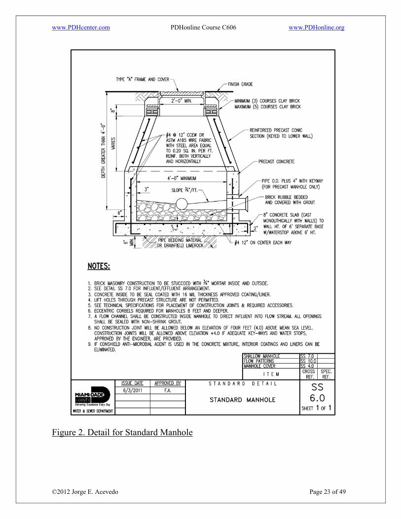
inches, except that distances up to 600 feet may be approved in cases where adequate modern cleaning equipment for such spacing is provided; As per MD-WASD design requirements, manhole to manhole runs shall be kept in a range no more than 400 feet without permission. Greater spacing may be permitted in larger sewers. Cleanouts may be used only for special conditions and shall not be substituted for manholes nor installed at the end of laterals greater than 150 feet in length. Manholes are essentially cylindrical in shape with the inside dimension sufficient to perform inspecting and cleaning operations without difficulty. As per RSWF, the minimum diameter of manholes shall be 48 inches; larger diameters are preferable for large diameter sewers. A minimum access diameter of 24 inches shall be provided. The following figure represents the standard details for a manhole based on MD-WASD standards.
www.PDHcenter.com PDHonline Course C606 www.PDHonline.org
©2012 Jorge E. Acevedo Page 23 of 49
Figure 2. Detail for Standard Manhole
www.PDHcenter.com PDHonline Course C606 www.PDHonline.org
©2012 Jorge E. Acevedo Page 24 of 49
The flow channel straight through a manhole should be made to conform as closely as possible in shape, and slope to that of the connecting sewers. The channel walls should be formed or shaped to the full height of the crown of the outlet sewer in such a manner to not obstruct maintenance, inspection or flow in the sewers. When curved flow channels are specified in manholes, including branch inlets, minimum required slopes should be increased to maintain acceptable velocities. The following figure represents a standard detail of flow patterns for invert channels based on MD-WASD standards.

www.PDHcenter.com PDHonline Course C606 www.PDHonline.org
©2012 Jorge E. Acevedo Page 25 of 49
Figure 3. Detail for flow invert channels

www.PDHcenter.com PDHonline Course C606 www.PDHonline.org
©2012 Jorge E. Acevedo Page 26 of 49
A bench shall be provided on each side of any manhole channel when the pipe diameter(s) are less than the manhole diameter. The bench should be sloped no less than ½ inch per foot (4 percent). No lateral sewer, service connection, or drop manhole pipe shall discharge onto the surface of the bench. Manholes shall be of the pre-cast concrete or poured-in-place concrete type. Manhole lift holes and grade adjustment rings shall be sealed with non-shrinking mortar or other material approved by the regulatory agency. Inlet and outlet pipes shall be joined to the manhole with a gasketed flexible watertight connection or any watertight connection arrangement that allows differential settlement of the pipe and manhole wall to take place. Watertight manhole covers are to be used wherever the manhole tops may be flooded by street runoff or high water. Locked manhole covers may be desirable in isolated easement locations or where vandalism may be a problem. If a sewer enters a manhole at an elevation considerable higher than the outgoing pipe, it is generally not satisfactory to let the stream merely pour into the manhole because the turbulence associated with the drops or falls will release hydrogen sulfide from the stream resulting in odor and corrosion problems. Drop manholes are usually provided in this case. As per RSWF, a drop pipe shall be provided for a sewer entering a manhole at an elevation higher than 24 inches in reference to the manhole invert. Where the difference in elevation between the incoming sewer and the manhole invert is less than 24 inches, the invert shall be filleted to prevent solids deposition. Drop manholes should be constructed with an outside drop connection. Inside drop connections, when necessary, shall be secured to the interior wall of the manhole and provide access for cleaning. Due to the unequal earth pressures that would result from the backfilling operation in the vicinity of the manhole, the entire outside drop connection shall be encased in concrete. The following figure represents a standard detail for a drop connection precast manhole based on MD-WASD standards.

www.PDHcenter.com PDHonline Course C606 www.PDHonline.org
©2012 Jorge E. Acevedo Page 27 of 49
Figure 4. Details for a drop Manhole

www.PDHcenter.com PDHonline Course C606 www.PDHonline.org
©2012 Jorge E. Acevedo Page 28 of 49
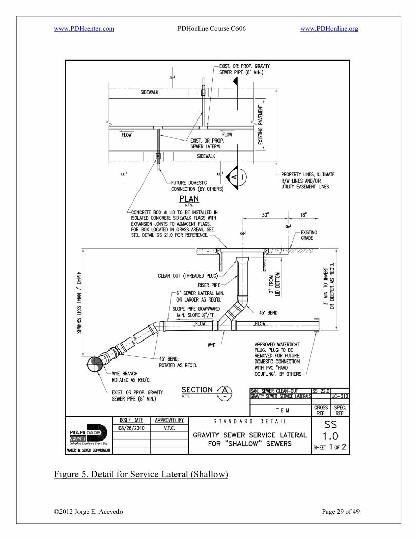
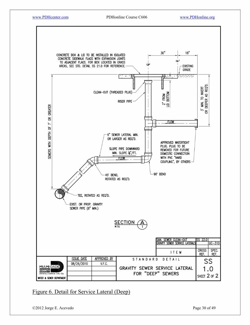
6.2.2 Siphons. Siphon in a sewer practice almost refers to an inverted siphon or depressed sewer, which would stand full even with no flow. Its purpose is to carry the flow under an obstruction such as stream or depressed highway and to regain as much elevation as possible after the obstruction has been passed. Siphons are often constructed with multiple barrels. The objective is to provide adequate self-cleansing velocities and maintenance flexibility under widely varying flow conditions. As per RSWF, inverted siphons shall not have less than two barrels, with a minimum pipe size of 6 inches. They shall be provided with necessary appurtenances for maintenance, convenient flushing, and cleaning equipment. The inlet and discharge structures shall have adequate clearances for cleaning equipment, inspection, and flushing. The design shall provide sufficient head and appropriate pipe sizes to secure velocities of at least 3.0 feet per second for design average flows. The inlet and outlet details shall be so arranged that the design average flow is diverted to one barrel, and so that either barrel may be cut out of service for cleaning. The vertical alignment should permit cleaning and maintenance. 6.2.3 Service laterals. Also called sewer connections or service connections are the branches between the street sewer and the property or curb lines, serving individual properties; they usually are required to be 4, 5, or 6 inch, preferably with a slope of 2%. Material, joints, and workmanship for service laterals should be equal to those of the street sewer to minimize infiltration and root intrusion. The following two figures represent the standard detail for gravity sewer service lateral for shallow and deep sewers based on MD-WASD standards.
www.PDHcenter.com PDHonline Course C606 www.PDHonline.org
©2012 Jorge E. Acevedo Page 29 of 49
Figure 5. Detail for Service Lateral (Shallow)
www.PDHcenter.com PDHonline Course C606 www.PDHonline.org
©2012 Jorge E. Acevedo Page 30 of 49
Figure 6. Detail for Service Lateral (Deep)

www.PDHcenter.com PDHonline Course C606 www.PDHonline.org
©2012 Jorge E. Acevedo Page 31 of 49
6.2.4 Equalization Storage Tanks. The use of tanks for the storage of peaking flows to prevent overflows from the collection and conveyance systems may be proposed. The stored wastewater is discharged back to the system during low flow periods. The storage can be online or offline. However, the approvals for the tanks are subject to the regulatory agency. Miami-Dade County does not allow this kind of appurtenance. The system shall be designed to handle the peak flow. 6.3 Depth of Sewer Depth of sewer is defined as the distance below ground elevation where the lines are installed. In general, sewers should be sufficiently deep to receive wastewater from basements and to prevent freezing. Insulation shall be provided for sewers that cannot be placed at a depth sufficient to prevent freezing. In the case of Miami-Dade County, due to the geographic location of the County where the average temperatures along the year do not reach the freezing point, insulation and/or depth to prevent freezing is not required. Due to the Flood Zone Classification within the Miami-Dade County, the construction of basement is not a common practice; Miami-Dade WASD recommends that the minimum depth shall be at least 3 feet at any terminal manhole. 6.4 Material selection Pipe for sanitary sewer construction generally is manufactured from various basic materials in accordance with nationally recognized product specifications. Each type of sanitary sewer pipe has its advantages and limitations. The selection of pipe materials should be evaluated carefully for given application. With the advancement of technology, new pipe materials are periodically being offered for sanitary sewer construction. The most common accepted materials currently available for sewer application are classified in rigid and flexible pipes. Rigid pipes include asbestos-cement pipe (ACP), cast iron pipe (CIP), concrete pipe and vitrified clay pipe (VCP); pipe materials in this classification derive a

www.PDHcenter.com PDHonline Course C606 www.PDHonline.org
©2012 Jorge E. Acevedo Page 32 of 49
substantial part of their basic earth load carrying capacity from the structural strength inherent in the rigid pipe wall. ACP and CIP are used for both gravity and force main lines; concrete pipe and VCP are used exclusively on gravity lines. Potential advantages in this classification include long laying lengths in some situations, and wide range of fitting available; potential disadvantage include subject to corrosion where acids are present and subject to shear or bean breakage when improperly bedded. Flexible pipes include ductile iron pipe (DIP), acrylonitrile-butadiene-styrene (ABS), polyethylene (PE), polyvinyl chloride (PVC), reinforced plastic mortar (RPM) and reinforced thermosetting resin (RTR). Pipe materials in this classification derive load carrying capacity from the interaction of the flexible pipe and the embedment soil affected by the deflection of the pipe to the point of equilibrium under load. All mentioned flexible pipes are commonly used in both gravity and force main lines. Potential advantage in this classification include light weight except DIP, high impact strength, and long laying lengths; potential disadvantages include limited of size available and subject to attack by certain organic chemicals. As per MD-WASD, it is required the use of PVC pipe or AWWA C900 PVC pipe within a public water supply wellfield cone of influence or in areas zoned industrial or commercial shall be as stated under "Tightness Standards" in Section UC-370. 6.5 Corrosion Resistance and Protection A sanitary sewer system is considered a potential corrosive environment where hydrogen sulfide (H2S) may be generated. In sanitary sewer systems, hydrogen sulfide causes various problems including odor, hazard to maintenance and corrosion. Retention of wastewater in anaerobic conditions may result in hydrogen sulfide generation; sulfide generation also takes place in partially full sanitary sewers at low velocities. Hydrogen sulfide may result in severe corrosive conditions for the unprotected sewer pipes produced from cementitious and metals. Such corrosive conditions occur when hydrogen sulfide derivates sulfuric acid due to bacterial action. The
www.PDHcenter.com PDHonline Course C606 www.PDHonline.org
©2012 Jorge E. Acevedo Page 33 of 49
corrosive effect of the sulfuric acid in the sewer lines will vary according to the type of pipe material, the concentration of the acid and the temperature. Due to potential corrosive conditions of the sewer system, the design engineer may choose specific corrosion resistant materials or various forms of corrosion protection. Corrosion may be controlled using corrosion protection which generally falls into the categories of lining or coating, or composition of material and thickness of sewer pipe materials. Metallic sewer pipes may also be protected from exterior wall corrosion through the use of suitable concrete encasement, insulating wrappings and/or cathode protection. 7. Additional Design Criteria Design of a sanitary sewer also involves other criteria and factors such as buoyancy, location to streams, crossings, separation with other utilities and lines that should be consider. 7.1 Location of sewer to streams Sewers crossing streams should be designed to cross the stream as nearly perpendicular to the stream flow as possible and shall be free from change in grade. Sewer systems shall be designed to minimize the number of stream crossings. Sewers located along streams shall be located outside of the stream bed and sufficiently removed from there to provide for future possible stream widening and to prevent pollution by siltation during construction. The sewer outfalls, headwalls, manholes, gate boxes, or other structures shall be located so they do not interfere with the free discharge of flood flows of the stream. As per RSWF, the top of all sewers entering or crossing streams shall be at a sufficient depth below the natural bottom of the stream bed to protect the sewer line. In general, the following cover requirements must be met: a) One foot of cover where the sewer is located in rock; b) Three feet of cover in other material. In major streams, more than 3 feet of cover may be required; and

www.PDHcenter.com PDHonline Course C606 www.PDHonline.org
©2012 Jorge E. Acevedo Page 34 of 49
c) In paved stream channels, the top of the sewer line should be placed below the bottom of the channel pavement. Less cover may be approved only if the proposed sewer crossing will not interfere with future modifications to the stream channel. Justification for requesting less cover shall be provided to the reviewing authority. 7.2 Aerial Crossings As per RSWF, support shall be provided for all joints in pipes utilized for aerial crossings. The supports shall be designed to prevent frost heave, overturning, and settlement. Precautions against freezing, such as insulation and increased slope, shall be provided. Expansion jointing shall be provided between above ground and belowground sewers. Where buried sewers change to aerial sewers, special construction techniques shall be used to minimize frost heaving. For aerial stream crossings, the impact of flood waters and debris shall be considered. The bottom of the pipe should be placed no lower than the elevation of the 50 year flood. Ductile iron pipe with mechanical joints is recommended. 7.3 Protection of Water Supplies When wastewater sewers are proposed in the vicinity of any water supply facilities, specific requirements should be used to confirm acceptable isolation distances in addition to general requirements. Water supply facilities include water wells, aquifers, water treatment plants, raw water lines, water distribution pipes and appurtenances. Currently, in order to protect the water supply, cross connections are prohibited. There shall be no physical connections between a public or private potable water supply system and a sewer, or appurtenance thereto which would permit the passage of any wastewater or polluted water into the potable supply. No water pipe shall pass through or come into contact with any part of a sewer manhole. While no general statement can be made to cover all conditions, it is generally recognized that sewers shall meet the requirements of the appropriate reviewing agency with respect to minimum distances from public water supply wells or other water supply sources and structures. Rule 62-555.314 F.A.C. include the following table, which clearly explain the location of public water system mains and the horizontal and vertical separation of the sewer lines.

www.PDHcenter.com PDHonline Course C606 www.PDHonline.org
©2012 Jorge E. Acevedo Page 35 of 49
Gravity or pressure sanitary sewer shall be laid preferably 10 feet or minimum 6 feet horizontally from any existing or proposed water main. The distance shall be measured edge to edge. For gravity sewers where it is not practical to maintain a 10-foot separation, the appropriate reviewing agency may allow deviation on a case-by-case basis, if supported by data from the design engineer. Such deviation may allow installation of the gravity sewer closer to a water main, provided that the water main is in a separate trench or on an undisturbed earth shelf located on one side of the gravity sewer and at an elevation so the bottom of the water main is at least 18 inches above the top of the sewer. MD-WASD has adapted this table as reference for approval of the lines separation. Sewers crossing water mains shall be laid to provide a minimum vertical distance of 12 inches between the outside of the water main and the outside of the sewer. This shall be the case where the water main is either above or below the sewer. For gravity sewer, 6 inches is the minimum and 12 inches preferred. The crossing shall be arranged so that the sewer joints will be equidistant and as far as possible from the water main joints. Where a water main crosses under a sewer, adequate structural support shall be provided for the sewer to maintain line and grade. When it is impossible to obtain proper horizontal and vertical separation as described above, one of the following methods must be specified: The sewer shall be designed and constructed equal to water pipe, and shall be pressure tested at 150 psi to assure water tightness. Either the water main or the sewer line may be encased in a watertight carrier pipe that extends 10 feet on both sides of the crossing, measured perpendicular to the water main. The carrier pipe shall be of materials approved by the regulatory agency for use in water main construction.

www.PDHcenter.com PDHonline Course C606 www.PDHonline.org
©2012 Jorge E. Acevedo Page 36 of 49
Figure 7. Location of Public Water System Mains in Accordance with F.A.C. Rule 62-555-314 7.4 Buoyancy. It is the ability or tendency to float in water or other fluid. Buoyancy of sewer shall be considered and flotation of the pipe shall be prevented with appropriate construction where high groundwater conditions are anticipated. 8. Installation and Testing Installation specifications shall contain appropriate requirements based on the criteria, standards, and requirements established by industry in its technical publications. Requirements shall be set forth in the specifications for the pipe and methods of bedding and backfilling thereof so as not to damage the pipe or its
www.PDHcenter.com PDHonline Course C606 www.PDHonline.org
©2012 Jorge E. Acevedo Page 37 of 49
joints, impede cleaning operations and future tapping, nor create excessive side fill pressures and deformation of the pipe shape, nor seriously impair flow capacity. The installation of joints and the materials used shall be included in the specifications. Sewer joints shall be designed to minimize infiltration and to prevent the entrance of roots throughout the life of the system. Service connections to the sewer main shall be watertight and not protrude into the sewer. If a saddle type connection is used, it shall be a device designed to join with the types of pipe that are to be connected. All materials used to make service connections shall be compatible with each other and with the pipe materials to be joined and shall be corrosion proof. 8.1 Trenching Sewer systems usually are constructed in ditches or trenches which are excavated in natural or disturbed soil, and then covered by refilling the trench to original ground line. This construction procedure is referred to as cut and cover, cut and fill or open cut. Trench section includes foundation, bedding, haunching, initial backfill, and final backfill; the pipe zone referred also as embedment material includes the bedding, haunching and initial backfill. The width of the trench shall be ample to allow the pipe to be laid and jointed properly and to allow the bedding and haunching to be placed and compacted to adequately support the pipe. The trench sides shall be kept as nearly vertical as possible. When wider trenches are specified, appropriate bedding class and pipe strength shall be used. The American Concrete Pipe Association recommends a trench width for concrete pipes based on 1.25Bc plus1 foot, where Bc is the outside diameter of the pipe in inches. As per MD-WASD standards, the width of the trench shall be equal to the outside diameter of the proposed pipe plus 24 inches.

www.PDHcenter.com PDHonline Course C606 www.PDHonline.org
©2012 Jorge E. Acevedo Page 38 of 49
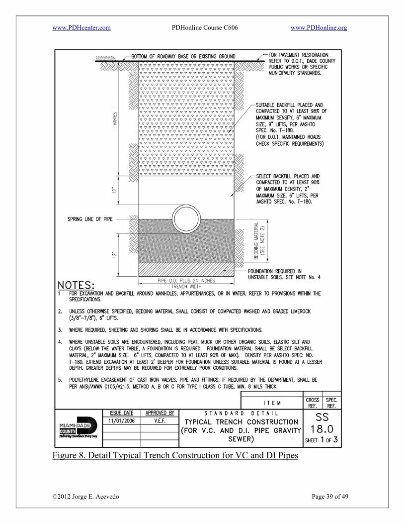
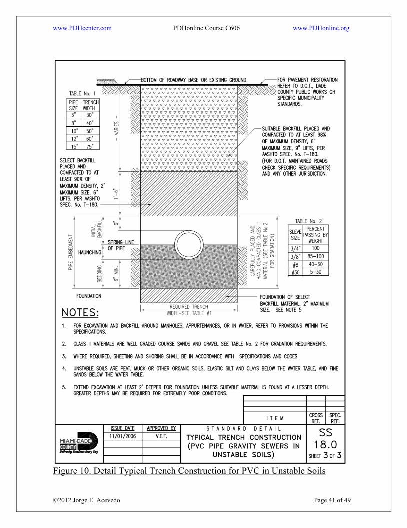
In unsupported, unstable soil the size and stiffness of the pipe, stiffness of the embedment and insitu soil and depth of cover shall be considered in determining the minimum trench width necessary to adequately support the pipe. Ledge rock, boulders, and large stones shall be removed to provide a minimum clearance of 4 inches below and on each side of all pipe(s). The following three figures represent the typical trench construction for gravity sewer VCP and DIP as well as PCV is stable and unstable soils based on MD-WASD standards.
www.PDHcenter.com PDHonline Course C606 www.PDHonline.org
©2012 Jorge E. Acevedo Page 39 of 49
Figure 8. Detail Typical Trench Construction for VC and DI Pipes

www.PDHcenter.com PDHonline Course C606 www.PDHonline.org
©2012 Jorge E. Acevedo Page 40 of 49
Figure 9. Detail Typical Trench Construction for PVC in Stable Soils
www.PDHcenter.com PDHonline Course C606 www.PDHonline.org
©2012 Jorge E. Acevedo Page 41 of 49
Figure 10. Detail Typical Trench Construction for PVC in Unstable Soils

www.PDHcenter.com PDHonline Course C606 www.PDHonline.org
©2012 Jorge E. Acevedo Page 42 of 49
8.2 Bedding The ability of a sewer pipe to safely resist the calculated soil load depends not only on its inherent strength but also on the distribution of the bedding reaction and on the lateral pressure acting against the sides of the sewer pipe. The contact between a pipe and the foundation on which it rests is the sewer pipe bedding. As per the American Concrete Pipe Association, bedding Classes A, B, C, and D are described. Class A Bedding, concrete cradle is used only with circular pipe, the pipe is bedded in non-reinforced or reinforced concrete having a thickness, d, and extending up the sides for a height equal to the outside diameter. The cradle should have a minimum width at least equal to the outside diameter of the pipe plus 8 inches. The backfill above the cradle is densely compacted and extends 12 inches above the crown of the pipe. In rock, especially where blasting is likely in the adjacent vicinity, the concrete cradle should be cushioned from the shock of the blasting which can be trans-mitted through the rock. Class B Bedding, Shaped or unshaped granular foundation. For a shaped subgrade with granular foundation, the bottom of the excavation is shaped to conform to the pipe surface but at least 2 inches greater than the outside dimensions of the pipe. The width should be sufficient to allow 6/10 of the outside pipe diameter for circular pipe, 7/10 of the outside span for arch and elliptical pipe, and the full bottom width of box sections to be bedded in fine granular fill placed in the shaped excavation. Densely compacted backfill should be placed at the sides of the pipe to a depth of at least 12 inches above the top of the pipe. For unshaped or a granular foundation without shaping is used only with circular pipe. The pipe is bedded in compacted granular material placed on the flat trench bottom. The granular bedding has a minimum thickness, d, and should extend at least halfway at the sides. The remainder of the side fills, and a minimum depth of 12 inches over the top of the pipe, should be filled with densely compacted material. Class C Bedding, shaped subgrade or granular foundation. For shaped subgrade, the pipe is bedded with ordinary care in a soil foundation, shaped to fit the lower part of the pipe exterior with reasonable closeness for a width of at least 50 percent of the outside diameter for a circular pipe, and 1/10 of the outside pipe rise for arch pipe, elliptical pipe and box sections. For trench installations the sides and area over the pipe are filled with lightly compacted backfill to a

www.PDHcenter.com PDHonline Course C606 www.PDHonline.org
©2012 Jorge E. Acevedo Page 43 of 49
minimum depth of 6 inches above the top of the pipe. For embankment installations the pipe should not project more than 90 percent of the vertical height of the pipe above the bedding. For granular foundation, used only with circular pipe, the pipe is bedded in compacted granular material or densely compacted backfill placed on a flat bottom trench. The bedding material should have a minimum thickness as indicated and should extend up the sides for a height of at least 1/6 the outside diameter. For trench installations the side fill and area over the pipe to a minimum depth of 6 inches should be filled with lightly compacted backfill. Class D Bedding, used only with circular pipe, little or no care, is exercised either to shape the foundation surface to fit the lower part of the pipe exterior, or to fill all spaces under and around the pipe with granular materials. However, the gradient of the bed should be smooth and true to established grade. This class of bedding also includes the case of pipe on rock foundations in which an earth cushion is provided under the pipe but is so shallow that the pipe, as it settles under the influence of vertical load, approaches contact with the rock. Bedding Class A, B, C, and D are also described in American Society for Testing Material (ASTM) under the standard ASTM C 12, Standard Practice For Installing Vitrified Clay Pipe Lines. Classes of bedding and encasements for pipe in trenches are defined as Class D wherein the pipe shall be placed on a firm and unyielding trench bottom with bell holes provided, Class C wherein the pipe shall be bedded in clean coarse-grained gravels and sands, Class B wherein the pipe shall be bedded in suitable material and Class A. Trenches shall be excavated to a width that will provide adequate working space, but not more than the maximum design width. Trench walls shall not be undercut. Bell holes shall be excavated to prevent point loading of the bells or couplings of laid pipe, and to establish full-length support of the pipe barrel. Soil classifications, under the Unified Soil Classification System, including manufactured materials, are grouped into five broad categories (I to V) according to their ability to develop an interacting system. Soils Class I includes crushed rock; Soil Class II includes well graded gravels (GW), poorly graded gravels (GP), well graded sands (SM), and poorly graded sands (SP); Soil Class III includes silty gravels (GM), clayey gravels (GC), silty sands (SM), clayey sands (SC); Class IV includes inorganic silts (MH, ML) and

www.PDHcenter.com PDHonline Course C606 www.PDHonline.org
©2012 Jorge E. Acevedo Page 44 of 49
inorganic clays (CH, CL); Class V includes Organic silts and clays (OL, OH) and peat (PT). These soil classes are described in the ASTM under the standard ASTM D2321 Standard Practice for Underground Installation of Thermoplastic Pipe for Sewers and Other Gravity-Flow Applications. Embedment materials for bedding, haunching and initial backfill, Classes I, II, or III, as described in ASTM D2321, shall be used and carefully compacted for all flexible pipe provided the proper strength pipe is used with the specified bedding to support the anticipated load, based on the type soil encountered and potential groundwater conditions. As per MD-WASD standards, for PVC pipe gravity sewer in unstable soils, only Class II materials are acceptable; unstable soils are peat, muck and other organic soils, elastic silt and clays below the water table and fine sands below the water table. All water entering the excavations or other parts of the work shall be removed until all the work has been completed. No sanitary sewer shall be used for the disposal of trench water, unless specifically approved by the engineer, and only then if the trench water does not ultimately arrive at existing pumping or wastewater treatment facilities. 8.3 Backfill Final backfill shall be of a suitable material removed from excavation except, where other material is specified. Debris, frozen material, large clods or stones, organic matter, or other unstable materials shall not be used for final backfill within 2 feet of the top of the pipe. Final backfill shall be placed in such a manner as not to disturb the alignment of the pipe. Final backfill does not need to be compacted to develop field supporting strength of the pipe. Final backfill may require compaction to prevent settlement of the ground surface. 8.4 Deflection and Lamping Test As per RSWF, deflection tests shall be performed on all flexible pipes. The test shall be conducted after the final backfill has been in place at least 30 days to permit stabilization of the soil-pipe system.
www.PDHcenter.com PDHonline Course C606 www.PDHonline.org
©2012 Jorge E. Acevedo Page 45 of 49
No pipe shall exceed a deflection of 5 percent. If deflection exceeds 5 percent, the pipe shall be excavated. Replacement or correction shall be accomplished in accordance with requirements in the approved specifications. As per MD-WASD standards, the deflection, or deformation of the pipe due to external loading, shall not exceed approximately 7.5 percent. Deflection shall be determined by passing an approved go/no go mandrel through the gravity sewer main. Deflection will be based on the average inside diameter as presented in ANSI/AWWA C900, "AWWA Standard for Polyvinyl Chloride (PVC) Pressure Pipe, 4 inches through 12 inches, for Water Distribution:", Table 1, for Poly (Vinyl Chloride) (PVC) C 900 pipe. The deflection may also be based on the average inside diameter as presented in ASTM D3034, Table XI.I, for PSM SDR35 PVC sewer pipe. The rigid ball or mandrel used for the deflection test shall have a diameter not less than 95 percent of the base inside diameter or average inside diameter of the pipe depending on which is specified in the ASTM Specification, including the appendix, to which the pipe is manufactured. The test shall be performed without mechanical pulling devices. For lamping test, each section of installed sewer lines shall show, from each end, a full circle of light. 8.5 Leakage Tests Leakage tests shall be specified. This may include appropriate water or low pressure air testing. The testing methods selected should take into consideration the range in groundwater elevations during the test and anticipated during the design life of the sewer. As per RSWF, the leakage exfiltration or infiltration shall not exceed 200 gallons per inch of pipe diameter per mile per day for any section of the system. An exfiltration or infiltration test shall be performed with a minimum positive head of 2 feet. As per Miami-Dade Code Chapter 24.43(4)(b)(i) no gravity sanitary sewer serving residential land use within the wellfield protection areas shall have an exfiltration rate greater than 50 gallons per inch pipe diameter per mile per day. For gravity sanitary sewer serving non-residential land use within the wellfield

www.PDHcenter.com PDHonline Course C606 www.PDHonline.org
©2012 Jorge E. Acevedo Page 46 of 49
protection areas shall have an exfiltration rate greater than 20 gallons per inch pipe diameter per mile per day. Prior to testing for infiltration, the system shall be pumped out so that normal infiltration conditions exist at the time of testing. The amounts of infiltration or exfiltration shall be determined by pumping into or out of calibrated drums, or by other approved methods. The exfiltration test will be conducted by filling the portion of the system being tested with water to a level which will provide a minimum head of 2-feet in a lateral connected to the test portion, or, in the event there are no laterals in the test portion, a minimum difference in elevation of 5-feet between the crown of the highest portion of the drain or sewer and the test level. If the ground water level is above the crown of the highest portion of the drain or sewer, the 5-foot differential shall be measured between the ground water level and the test level. Where insufficient depth of cover is available to produce a 5-foot differential, the maximum differential producible between ground water elevation and a test elevation set to avoid flow out of low manholes or into adjacent structures connected to the test section shall be used. Where infiltration or exfiltration exceeds the allowable limits specified herein, the defective pipe, joints, or other faulty construction shall be located and repaired. 8.6 Air test As per RSWF, the air test shall, as a minimum, conform to the test procedure described in ASTM C 828 for clay pipe, ASTM C 924 for concrete pipe, ASTM F 1417 for plastic pipe, and for other materials test procedures approved by the regulatory agency. 8.7 Inspection and Testing of Manholes As per RSWF, the specifications shall include a requirement for inspection and testing for watertightness or damage prior to placing into service. Air testing, if specified for concrete sewer manholes, shall conform to the test procedures described in ASTM C 1244. As per MD-WASD standards, each manhole or other appurtenance to the system shall have the specified size and form, be watertight, neatly and substantially
www.PDHcenter.com PDHonline Course C606 www.PDHonline.org
©2012 Jorge E. Acevedo Page 47 of 49
made with the top set permanently to exact position and grade, and shall serve well and fully its intended use. Any defects found in the system shall be corrected by the Contractor in accordance with the requirements of the Specifications or the MD-WASD Design and Construction Standards, as approved by the Engineer. 9. Summary Specification for the design, materials, and installation requirements of the gravity sanitary sewer system has been published by many utilities, cities, counties, and states nationwide. Sanitary sewer capacities should be designed for the estimated ultimate tributary area population. The service life, defined as the operational life of a sewage facility, should exceed the design period of the facility, provided it is designed, constructed and maintained properly. The criteria for hydraulic design sewer pipe is evaluated based on the size and type of the pipe, design period, design depth and peak flows. Miami-Dade County has developed and implemented a sewage flow study and it has been adapted into Miami-Dade Code under the Section 24-43.1(5) In general, the design of gravity sanitary sewers systems shall be based on steady uniform flow analysis employing the Manning equation. Compliance with the State Rules and Regulations, in Miami-Dade County, gravity sanitary sewer systems shall be designed in accordance with the minimum standards for design and construction published by MD-WASD and approved by the MD-RER. 10. Acronyms AADF: Annual average daily flow ABS: Acrylonitrile butadiene styrene ADF: Annual daily flow ASCE: American Society of Civil Engineers ASTM: American Society for Testing Materials
www.PDHcenter.com PDHonline Course C606 www.PDHonline.org
©2012 Jorge E. Acevedo Page 48 of 49
AWWA: American Water Works Association cfs: cubic feet per second CIP: Cast Iron Pipe CT: Census tract DIP: Ductile Iron Pipe F.A.C. Florida Administrative Code FDEP: Florida Department of Environmental Protection FM: Force main gpapd: gallons per acre per day gpcd: gallons per capita per day gpd: gallons per day gped: gallons per employee per day gph: gallons per hour gpm: gallons per minute GWI: Groundwater Infiltration HGL: Hydraulic Grade Line I/I: Infiltration/Inflow MD-DERM: Miami-Dade Department of Environmental Resources Management MD-RER: Miami-Dade Regulatory and Economic Resources MD-WASD: Miami-Dade Water and Sewer Department mgd: million gallons per day MH: Manhole n: Manning roughness coefficient OSHA: Occupational Safety and Health Administration psi: pound per square inch PE: Polyethylene P.E.: Professional Engineer PVC: Polyvinyl Chloride RPM: Reinforced Plastic Mortar RSWF: Recommended Standards for Wastewater Facilities S: Slope Sq ft: Square feet USEPA: United States Environmental Protection Agency VCP: Vitrified Clay Pipe

www.PDHcenter.com PDHonline Course C606 www.PDHonline.org
©2012 Jorge E. Acevedo Page 49 of 49
11. Reference and Standard Manual Publications • Alternative Wastewater Collection Systems (1991). EPA 625 1-91 024. US EPA. National Service Center for Environmental Publications. www.nepis.epa.gov • Concrete Pipe & Box Culvert Installation (2007). American Concrete Pipe Association. 1303 West Walnut Hill Lane, Suite 305, Irving, Texas 75308-3008. www.concrete-pipe.org • Donation Standard Specification and Details for Design and Construction. Donation Wastewater Gravity Systems, UC-250, UC-290, UC-300, UC-310, UC-320, UC-320, UC-350, and UC-370. Miami-Dade Water and Sewer Department. 3071 SW 38th Ave, Miami, FL 33146. www.miamidade.gov/water/design-construction-standards.asp • Gravity Sanitary Sewer Design and Construction – MOP FD-5, 2nd Edition, (2007) Water Environment Federation, 601 Wythe Street, Alexandria, VA 22314. www.wef.org • Manual of Practice No. 7. Wastewater Collection Systems Management (1999). Water Environment Federation, 601 Wythe Street, Alexandria, VA 22314. www.wef.org • Manual of Practice No. FD-12. Alternative Sewer Systems (1986). Water Environment Federation, 601 Wythe Street, Alexandria, VA 22314. www.wef.org • Manual of Practice No. FD-4. Design of Wastewater and Stormwater Pumping Stations (1993). Water Environment Federation, 601 Wythe Street, Alexandria, VA 22314. www.wef.org • Odor and Corrosion Control in Sanitary Sewerage Systems and Treatment Plants (1985). EPA 625 1-85 018. US EPA, National Service Center for Environmental Publications. www.nepis.epa.gov • Operation and Maintenance of Wastewater Collection Systems Volume I (1999) and Volume II (1998). California State University, Department of Civil Engineering, 6000 J Street, Sacramento, California 95819. www.owp.csus.edu/courses • Recommended Standards for Wastewater Facilities (2004). Health Research Inc. Education Service Division, P.O. Box 7126, Albany, New York 12224. www.dep.state.fl.us/water/wastewater/docs/10statestandards_wastewater.pdf • Standard Practice for Installing Vitrified Clay Pipe Lines, ASTM C12-09, American Society for Testing Material, www.astm.org/Standards/C12.htm