GRAVITY BASE FOUNDATIONS FOR OFFSHORE WIND FARMS
121
GRAVITY BASE FOUNDATIONS FOR OFFSHORE WIND FARMS MARINE OPERATIONS AND INSTALLATION PROCESSES Ismael Ruiz de Temiño Alonso Master in European Construction Engineering Supervisor: Francisco Ballester Moderator: Joaquin Diaz
Transcript of GRAVITY BASE FOUNDATIONS FOR OFFSHORE WIND FARMS
GRAVITY BASE FOUNDATIONS FOR OFFSHORE WIND FARMS
MARINE OPERATIONS AND INSTALLATION PROCESSES
Ismael Ruiz de Temiño Alonso
Master in European Construction Engineering
Supervisor: Francisco Ballester
Moderator: Joaquin Diaz
GRAVITY BASE FOUNDATIONS FOR
OFFSHORE WIND FARMS
MARINE OPERATIONS AND INSTALLATION PROCESSES
Author: Ismael Ruiz de Temiño Alonso
Master in European Construction Engineering
2012- 2013
August 2013
Supervisor: Francisco Ballester Muñoz, University of Cantabria
Moderator: Joaquin Diaz, University of Applied Sciences Giessen-Friedberg

i
ABSTRACT
Marine operations required in the installation of gravity base foundations for
offshore wind farms were studied. This dissertation analyses the operations of
transport, seabed preparation, installation and scour protection. This analysis was
carried out through the study of the eight most relevant offshore wind farms with
gravity base foundations, four significant foundation designs, and the application
of techniques from other offshore construction sectors. Within each operation,
the main procedures both used so far and expected for the future were
investigated. It was also identified the main factors to consider in each operation
and the means required. Further analysis studied different transport and
installation configurations.
KEYWORDS
Offshore wind energy; Offshore wind farms; Gravity base foundations; Marine
operations; Transport; Installation; Seabed preparation; Scour; Procedures; Wind
turbines; Pre-assembly; Future trends.
ii
RESEARCH STATEMENT
This dissertation is the result of an individual research of the author and the
collaboration with the research group GITECO. The Construction Technology
Applied Research group (GITECO) was born in 2002 and since then, it has
successfully developed more than 70 projects related with civil construction
sector. GITECO is part of the Department of Transports and Technology of Projects
and Processes of the University of Cantabria and it operates in the School of Civil
Engineering in Santander (Spain).
One of the research areas on which GITECO is currently working is gravity base
foundations for offshore wind farms. The author has developed this dissertation
as an interesting area for the research group, and both sides have exchanged
information to establish a mutually beneficial collaboration.

iii
ACKNOWLEDGEMENTS
I would like to express my gratitude to my supervisor, Francisco Ballester, and the
research group GITECO for their help and advises with the dissertation.
I must also acknowledge Daniel Castro, coordinator of the Master, and the
professor Jorge Rodriguez, for their assistance during the whole programme. I
would like to express my deep gratitude to all the people in VIA University that
welcomed us so warmly and helped us during our stay in Denmark, especially to
Inga Sørensen and Regner Bæk. Thanks also goes to the professors of the Master
and, of course, to my fellow students, with whom I have shared a beautiful
experience.
A very special thanks goes to my friends, especially to all the exceptional people I
met in Santander over the last few years, and all friends I have in Burgos. Spending
some time with them gives me energy to accomplish anything.
Finally, and most importantly, I would like to thank my father Luis, my mother
Elena, my brother Oscar, and my sister Alba, for their endless support and
encouragement during all the stages of my education, and of my life. I would also
like to thank my partner Mª Eugenia, for her assistance, her kindness and,
especially, for her love.
iv
CONTENTS
ABSTRACT ............................................................................................................. i
ACKNOWLEDGEMENTS ...................................................................................... iii
1. INTRODUCTION ............................................................................................... 1
1.1. BACKGROUND ........................................................................................... 1
1.2. AIMS AND OBJECTIVES .............................................................................. 3
1.3. RESEARCH METHODOLOGY ....................................................................... 4
1.4. LIMITATIONS AND SCOPE .......................................................................... 4
1.5. DISSERTATION REPORT OUTLINE ............................................................... 5
2. TRANSPORT ..................................................................................................... 6
2.1. INTRODUCTION ......................................................................................... 6
2.2. TRANSPORT PROCEDURES ......................................................................... 6
2.3. FACTORS ................................................................................................. 11
2.4. TRANSPORT MEANS ................................................................................ 18
3. SEABED PREPARATION .................................................................................. 20
3.1. INTRODUCTION ....................................................................................... 20
3.2. SEABED PREPARATION PROCEDURES ...................................................... 20
3.3. FACTORS ................................................................................................. 24
3.4. MEANS .................................................................................................... 28
4. FOUNDATION INSTALLATION ........................................................................ 31
4.1. INTRODUCTION ....................................................................................... 31
4.2. FOUNDATION INSTALLATION PROCEDURES ............................................ 31
4.3. FACTORS ................................................................................................. 37
4.4. MEANS .................................................................................................... 39
5. SCOUR PROTECTION ...................................................................................... 40
5.1. INTRODUCTION ....................................................................................... 40
5.2. SCOUR BASIS ........................................................................................... 40
5.3. SCOUR PROTECTION ................................................................................ 42
5.4. FACTORS ................................................................................................. 44
5.5. MEANS .................................................................................................... 46
6. FURTHER ANALYSIS: PREASSEMBLY AND ON SITE ASSEMBLY ....................... 47
6.1. INTRODUCTION ....................................................................................... 47
6.2. CONFIGURATION POSSIBILITIES ............................................................... 47
v
6.3. COSTS ...................................................................................................... 49
6.4. STABILITY ................................................................................................ 51
6.5. CONFIGURATION CONCLUSIONS ............................................................. 54
7. CONCLUSIONS AND RECOMMENDATIONS .................................................... 55
7.1. CONCLUSIONS ......................................................................................... 55
7.2. RECOMMENDATIONS .............................................................................. 56
REFERENCES ...................................................................................................... 57
APENDIX A: LISTS OF WIND FARMS………………………………….…………………………….60
A1. LIST OF OPERATIONAL WIND FARMS……………………………………………………….61
A2. LIST OF OFFSHORE WIND FARM PROJECTS…………….……………………………….63
A3. LIST OF WINDFARMS WITH GBS……………………………………………………………….64
APENDIX B: WIND FARMS AND SOLUTIONS REVIEW………………………..…………….65
B1. WIND FARMS AND FUTURE SOLUTIONS REVIEW…………………………….……….66
B2. FUTURE FOUNDATION SOLUTIONS………………………...……………………………….97
vi
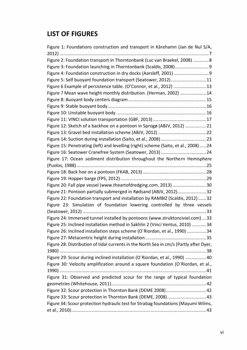
LIST OF FIGURES
Figure 1: Foundations construction and transport in Kårehamn (Jan de Nul S/A,
2012) ................................................................................................................... 7
Figure 2: Foundation transport in Thorntonbank (Luc van Braekel, 2008) ............ 8
Figure 3: Foundation launching in Thorntonbank (Scaldis, 2008) .......................... 9
Figure 4: Foundation construction in dry docks (Aarsleff, 2001) ........................... 9
Figure 5: Self buoyant foundation transport (Seatower, 2012) ........................... 11
Figure 6 Example of persistence table. (O’Connor, et al., 2012) ......................... 13
Figure 7 Mean wave height monthly distribution. (Herman, 2002) .................... 14
Figure 8: Buoyant body centers diagram ............................................................ 15
Figure 9: Stable buoyant body............................................................................ 16
Figure 10: Unstable buoyant body ..................................................................... 16
Figure 11: VINCI solution transportation (GBF, 2013) ......................................... 17
Figure 12: Sketch of a backhoe on a pontoon in Sprogø (ABJV, 2012) ................ 21
Figure 13: Gravel bed installation scheme (ABJV, 2012) ..................................... 22
Figure 14: Suction during installation (Saito, et al., 2008) ................................... 23
Figure 15: Penetrating (left) and levelling (right) scheme (Saito, et al., 2008) ..... 24
Figure 16: Seatower Cranefree System (Seatower, 2013) ................................... 24
Figure 17: Ocean sediment distribution throughout the Northern Hemisphere
(Puolos, 1988) .................................................................................................... 25
Figure 18: Back hoe on a pontoon (FKAB, 2013) ................................................. 28
Figure 19: Hopper barge (FPS, 2012) .................................................................. 29
Figure 20: Fall pipe vessel (www.theartofdredging.com, 2013) .......................... 30
Figure 21: Pontoon partially submerged in Rødsand (ABJV, 2012) ...................... 32
Figure 22: Foundation transport and installation by RAMBIZ (Scaldis, 2012) ...... 32
Figure 23: Simulation of foundation lowering controlled by three vessels
(Seatower, 2012) ............................................................................................... 33
Figure 24: Immersed tunnel installed by pontoons (www.struktonciviel.com) ... 33
Figure 25: Inclined installation method in Sakhlin 2 (Vinci Ventus, 2010) ........... 34
Figure 26: Inclined installation steps scheme (O´Riordan, et al., 1990) ............... 34
Figure 27: Metacentric height during installation ............................................... 35
Figure 28: Distribution of tidal currents in the North Sea in cm/s (Partly after Dyer,
1980) ................................................................................................................. 38
Figure 29: Scour during inclined installation (O´Riordan, et al., 1990) ................ 40
Figure 30: Velocity amplification around a square foundation (O´Riordan, et al.,
1990) ................................................................................................................. 41
Figure 31: Observed and predicted scour for the range of typical foundation
geometries (Whitehouse, 2011) ......................................................................... 42
Figure 32: Scour protection in Thornton Bank (DEME 2008) ............................... 42
Figure 33: Scour protection in Thornton Bank (DEME, 2008) .............................. 43
Figure 34: Scour protection hydraulic test for Strabag foundations (Mayumi Wilms,
et al., 2010) ........................................................................................................ 43

vii
Figure 35: Scour protection with composite and rubber mat tests (Deltares, 2010)
.......................................................................................................................... 44
Figure 36: Scour test results for conical transition and smooth top transition
(Whitehouse, 2004) ........................................................................................... 45
Figure 37: Foundation installation in Sprogø (ABJV, 2009).................................. 47
Figure 38: Pre-assembled turbine being installed in a jacket foundation
(turbineel.net) ................................................................................................... 48
Figure 39: Foundation installation in Middelgrunden (Power technology, 2001) 48
Figure 40: Complete pre-assembled turbine installation (GBF, 2012) ................. 49
Figure 41: Gravity foundation example .............................................................. 52
Figure 42: Draft with different configurations .................................................... 53
Figure 43: Metacentric height with different configurations .............................. 53
LIST OF TABLES
Table 1: Indicative values of prepared seabed area, excavation material and
material for gravel bed....................................................................................... 22
Table 2: Typical scope of geophysical survey for platforms (International Society
for Soil Mechanics and Geotechnical Engineering, 2005) ................................... 26
Table 3: Typical scope of geotechnical survey for platforms (International Society
for Soil Mechanics and Geotechnical Engineering, 2005) ................................... 27
Table 4: kt and kf values (O´Riordan, et al., 1990) .............................................. 36

viii
LIST OF ABBREVIATIONS
GBF: Gravity Base Foundations
GPS: Global Positioning System
MW: Megawatts
SPMT: Self Propelled Modular Transporter
1
1. INTRODUCTION
1.1. BACKGROUND
The global warming of our planet along with the limitation of supplies of
conventional fuels has led humanity to search for new energy sources. In this
context, the EU-27 has committed to reduce its greenhouse gasses emission by at
least 20 % in the year 2020 compared to 1990 values. In 2009, the emissions of
EU-27 were approximately 17.3% below 1990 level (European Environment
Agency, 2010).
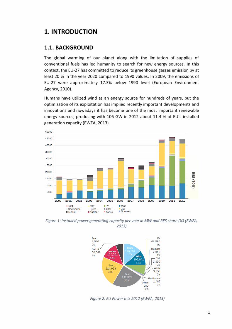
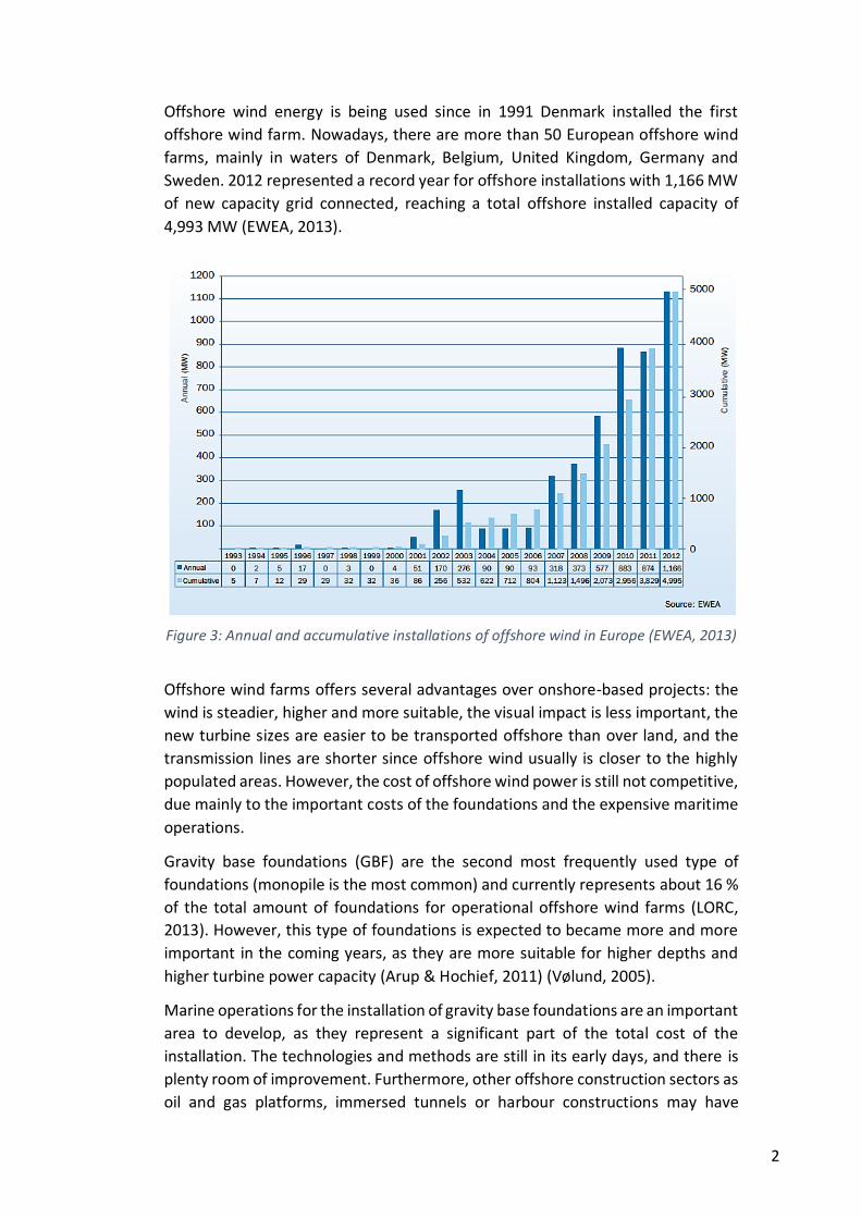
Humans have utilized wind as an energy source for hundreds of years, but the
optimization of its exploitation has implied recently important developments and
innovations and nowadays it has become one of the most important renewable
energy sources, producing with 106 GW in 2012 about 11.4 % of EU’s installed
generation capacity (EWEA, 2013).
Figure 1: Installed power generating capacity per year in MW and RES share (%) (EWEA, 2013)
Figure 2: EU Power mix 2012 (EWEA, 2013)
2
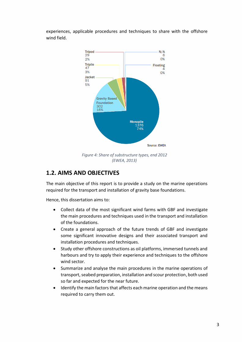
Offshore wind energy is being used since in 1991 Denmark installed the first
offshore wind farm. Nowadays, there are more than 50 European offshore wind
farms, mainly in waters of Denmark, Belgium, United Kingdom, Germany and
Sweden. 2012 represented a record year for offshore installations with 1,166 MW
of new capacity grid connected, reaching a total offshore installed capacity of
4,993 MW (EWEA, 2013).
Offshore wind farms offers several advantages over onshore-based projects: the
wind is steadier, higher and more suitable, the visual impact is less important, the
new turbine sizes are easier to be transported offshore than over land, and the
transmission lines are shorter since offshore wind usually is closer to the highly
populated areas. However, the cost of offshore wind power is still not competitive,
due mainly to the important costs of the foundations and the expensive maritime
operations.
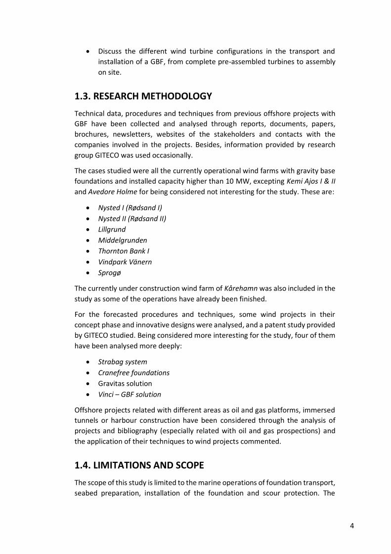
Gravity base foundations (GBF) are the second most frequently used type of
foundations (monopile is the most common) and currently represents about 16 %
of the total amount of foundations for operational offshore wind farms (LORC,
2013). However, this type of foundations is expected to became more and more
important in the coming years, as they are more suitable for higher depths and
higher turbine power capacity (Arup & Hochief, 2011) (Vølund, 2005).
Marine operations for the installation of gravity base foundations are an important
area to develop, as they represent a significant part of the total cost of the
installation. The technologies and methods are still in its early days, and there is
plenty room of improvement. Furthermore, other offshore construction sectors as
oil and gas platforms, immersed tunnels or harbour constructions may have
Figure 3: Annual and accumulative installations of offshore wind in Europe (EWEA, 2013)
3
experiences, applicable procedures and techniques to share with the offshore
wind field.
1.2. AIMS AND OBJECTIVES
The main objective of this report is to provide a study on the marine operations
required for the transport and installation of gravity base foundations.
Hence, this dissertation aims to:
Collect data of the most significant wind farms with GBF and investigate
the main procedures and techniques used in the transport and installation
of the foundations.
Create a general approach of the future trends of GBF and investigate
some significant innovative designs and their associated transport and
installation procedures and techniques.
Study other offshore constructions as oil platforms, immersed tunnels and
harbours and try to apply their experience and techniques to the offshore
wind sector.
Summarize and analyse the main procedures in the marine operations of
transport, seabed preparation, installation and scour protection, both used
so far and expected for the near future.
Identify the main factors that affects each marine operation and the means
required to carry them out.
Figure 4: Share of substructure types, end 2012 (EWEA, 2013)
4
Discuss the different wind turbine configurations in the transport and
installation of a GBF, from complete pre-assembled turbines to assembly
on site.
1.3. RESEARCH METHODOLOGY
Technical data, procedures and techniques from previous offshore projects with
GBF have been collected and analysed through reports, documents, papers,
brochures, newsletters, websites of the stakeholders and contacts with the
companies involved in the projects. Besides, information provided by research
group GITECO was used occasionally.
The cases studied were all the currently operational wind farms with gravity base
foundations and installed capacity higher than 10 MW, excepting Kemi Ajos I & II
and Avedore Holme for being considered not interesting for the study. These are:
Nysted I (Rødsand I)
Nysted II (Rødsand II)
Lillgrund
Middelgrunden
Thornton Bank I
Vindpark Vänern
Sprogø
The currently under construction wind farm of Kårehamn was also included in the
study as some of the operations have already been finished.
For the forecasted procedures and techniques, some wind projects in their
concept phase and innovative designs were analysed, and a patent study provided
by GITECO studied. Being considered more interesting for the study, four of them
have been analysed more deeply:
Strabag system
Cranefree foundations
Gravitas solution
Vinci – GBF solution
Offshore projects related with different areas as oil and gas platforms, immersed
tunnels or harbour construction have been considered through the analysis of
projects and bibliography (especially related with oil and gas prospections) and
the application of their techniques to wind projects commented.
1.4. LIMITATIONS AND SCOPE
The scope of this study is limited to the marine operations of foundation transport,
seabed preparation, installation of the foundation and scour protection. The
5
document does not cover, therefore, any process of transport and installation of
wind turbine components.
The study is focused on gravity base foundations for offshore wind farms, so it
does not cover any other type of foundations or GBF for other purposes.
Wind farms with less installed capacity than 10 MW and experimental wind farms
were not considered. Wind turbines installed in distances below 1 km from the
shore or water depths lower than 3 meters were not considered either.
This dissertation has been carried out between mid-April 2013 and mid- August
2013.
1.5. DISSERTATION REPORT OUTLINE
The report was divided in six chapters. After the first introductory section, it was
devoted one chapter for each marine operation considered: transport, seabed
preparation, foundation installation and scour protection. The sixth and final
chapter studies the different possibilities of configuration of turbine and
foundation during the operations of transport and installation.
The sections devoted to the marine operations are, at the same time, subdivided
in four main sections: introduction, procedures, factors and means.

6
2. TRANSPORT
2.1. INTRODUCTION
The operation of transport is one of the most important aspects in the
implementation of offshore wind farms with gravity base foundations. This is due
to the huge weights and dimensions of these structures. It has already been
transported foundations of up to 3,000 tonnes and 40 m height, and it is expected
that the coming foundations, designed for deeper waters, will reach up to 7,000
tonnes. These huge dimensions require special vessels and means, whose
availability is limited, and with very important costs. Even it may be necessary
specifically built vessels for one project.
Transport operation affects the whole project. From the concept phase,
transportation is taken into account and even some designs are specially aimed at
facilitating the transport of the foundations. The transport planning is very
important as well, since the means of transport are so expensive that a mistake in
the planning would trigger important costs for the project.
Market is moving currently to decrease the high risks and costs of depending so
much in specific vessels. The trend of installing wind farms in deeper waters
triggers bigger and heavier solutions that makes unsuitable the methods used so
far, and lead to buoyant or semi-buoyant solutions.
In this chapter it will be analysed the main transport procedures both used so far
and proposed for the near future, the most important aspects to consider, and the
means required.
2.2. TRANSPORT PROCEDURES
The transport of gravity base foundations may be carried out in three main
procedures:
Group transport with large barges or pontoons
Individual transport by heavy lift vessels
Transport of buoyant foundations
2.2.1. GROUP TRANSPORT IN LARGE BARGES OR PONTOONS
This procedure is the most commonly used in the transport of gravity base
foundations, and it has been chosen for the operational wind farms of Nysted I
(Rødsand I), Nysted II (Rødsand II), Lillgrund, Sprogø and Kårehamn (under
construction).
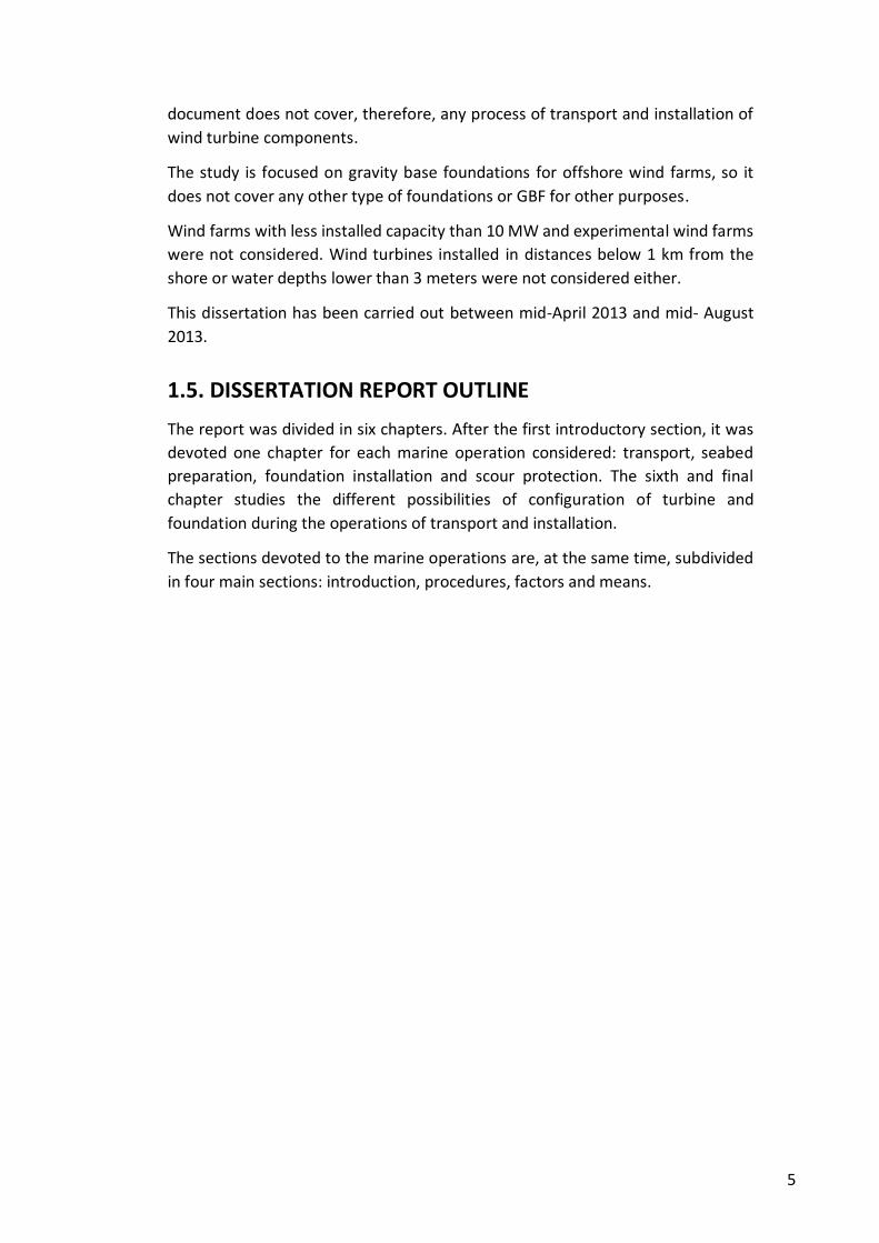
In this way of transportation, the construction of the foundation is carried out
directly on flattop barges or pontoons, and when all the foundations of the barge
7
are finished, they are carried to the wind farm. Tugs are required in order to tow
not self-propelled barges. Some vessels used, as the pontoon “Giant 4”, are self-
propelled, so tugs are necessary only for auxiliary operations. Up to 12 foundations
have been transported in one barge (Kårehamn wind farm), but it depends on the
dimensions and weight of the foundations.
When the foundations arrive to the wind farm, a special vessel, as a heavy lift
vessel, is necessary to pick up each foundation and start the installation process.
Semi-submersible vessels (as the pontoon “Giant 4” or other semi-submersible
barges) may be used, both to facilitate the assembling of the foundation with the
heavy lift vessel and to reduce the weight that this vessel have to hoist. In some
cases this operation of sinking some centimetres the barge is compulsory, as the
heavy lift vessel may not have enough lifting capacity.
The main advantage of this procedure is that it allows the transport of several
foundations at a time, making it more effective for large distances, as it optimize
the transport. Thus, in the offshore wind farms where this procedure was used,
the transport distance ranged from 200 km to 2,000 km (Kårehamn wind farm).
Besides, the construction of the foundation is carried out directly on barges, so the
launching operation is avoided. On the other hand, a heavy lift vessel is required
to pick up the foundation from the barge or pontoon. The availability of these
vessels is low and the cost very important.
Regarding the future of this type of transport, it seems to be less suitable for
heavier and bigger foundations, not for the transport itself (there are pontoons
capable of carrying more than 24,000 tonnes), but because the existing heavy lift
vessels required for hoisting and installing the foundations are not capable of
lifting so heavy weights. The adaptation of other heavy crane vessels, semi-
submersible pontoons and some degree of buoyancy of the foundation may allow
the use of this transport procedure for bigger foundations.
Figure 5: Foundations construction and transport in Kårehamn (Jan de Nul S/A, 2012)
8
2.2.2. INDIVIDUAL TRANSPORT BY HEAVY LIFT VESSELS
This procedure is quite common, and it has been chosen in operational wind farms
as important as Middelgrunden or Throntonbank I.
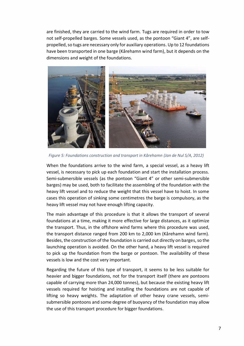
The main characteristic of this type of transport is that a heavy lift vessel, picks up
the foundation from the harbour, carries it directly to the wind farm and installs it
on the seabed. In the previous procedure, the heavy lift vessel only picked up the
foundation when it was already in the wind farm, and it installed the foundation.
In this one, the heavy lift vessel carries out the transport as well, one by one.
In the previous procedure, the foundations were built directly on the barges or
pontoons that would transport it. In this one, the heavy lift vessel will pick up the
foundations from the quay, so the construction site and launching operation must
be planned. The main construction and launching procedures for this type of
transport are:
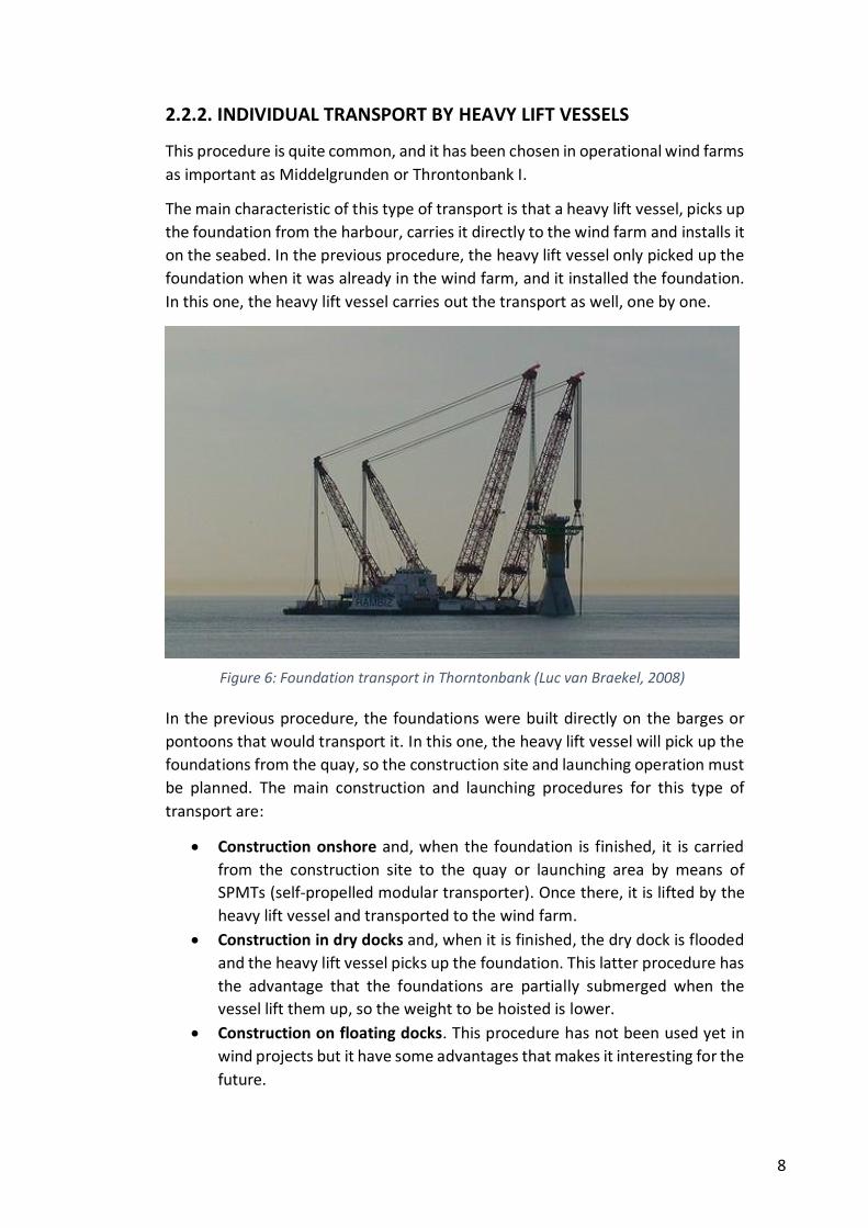
Construction onshore and, when the foundation is finished, it is carried
from the construction site to the quay or launching area by means of
SPMTs (self-propelled modular transporter). Once there, it is lifted by the
heavy lift vessel and transported to the wind farm.
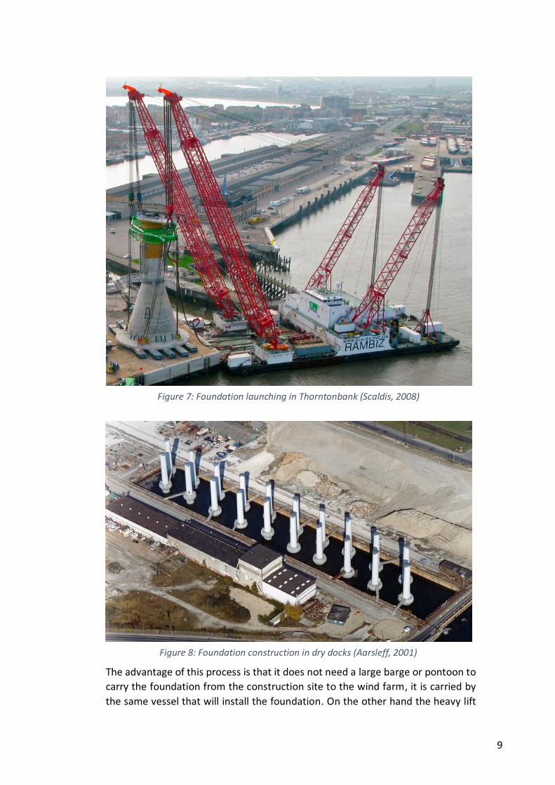
Construction in dry docks and, when it is finished, the dry dock is flooded
and the heavy lift vessel picks up the foundation. This latter procedure has
the advantage that the foundations are partially submerged when the
vessel lift them up, so the weight to be hoisted is lower.
Construction on floating docks. This procedure has not been used yet in
wind projects but it have some advantages that makes it interesting for the
future.
Figure 6: Foundation transport in Thorntonbank (Luc van Braekel, 2008)
9
The advantage of this process is that it does not need a large barge or pontoon to
carry the foundation from the construction site to the wind farm, it is carried by
the same vessel that will install the foundation. On the other hand the heavy lift
Figure 7: Foundation launching in Thorntonbank (Scaldis, 2008)
Figure 8: Foundation construction in dry docks (Aarsleff, 2001)

10
vessel only is capable of transporting one foundation at a time. The conclusion is
that this procedure is more suitable than the former for short distances. Thus, in
Middelgrunden the wind farm was only a few kilometres away from the harbour
(in Copenhagen).
For the future, this type of transport has been chosen (with some variations) in
some design proposals, as Strabag solution, where the transport is carried out by
means of a specifically built vessel. The foundations of this system are suitable for
depths up to 60 m and they weigh up to 6,000 tonnes, so the transportation is
carried out with the foundation semi submerged. This example points out the
future trends of this procedure, with a partially submerged foundation to reduce
the enormous weights.
2.2.3. BUOYAN SOLUTIONS TRANSPORT
The tendency to install offshore wind farms in deeper waters and consequently
the increase in the size and weight of the foundations makes quite difficult the two
previous ways of transport, as currently it does not exist heavy lift vessels capable
of lifting more weight. It could be constructed a specifically built vessel for the
task, but it would increase not only the costs of transport, but also the risks of so
restricted availability. Thus, the trends point to self-buoyant solutions that are
towed to the wind farm by means of standard tugs. The availability of these tugs
is much higher than heavy lift vessels used in the previous types of transport, and
the cost is lower.
As in the previous procedure, the construction site and launching operation must
be planned. Thus, there are three main types of construction and launching
operations for buoyant solutions:
a) Construction onshore. One simple method may be the construction of the
foundation onshore and, when finished, it is transported to a launching area
where a submersible pontoon lower the foundation until it is buoyant, and
then, it is assembled to the tugs or transport vessels used.
b) Construction in dry docks. Other important method that has been used in
the construction of immersed tunnels is the construction of the foundation in
dry docks that are flooded when the foundation is ready to be transported.
c) Construction in floating docks. Floating docks has some advantages as the
high efficiencies of construction and the not dependency of expensive
shipyards or other facilities. On the other hand, the curing of the concrete
occurs in the sea water, what has to be considered carefully, and the
availability of suitable floating docks may be limited.
This procedure of self-buoyant solution is quite innovative and no operational
wind farms have used it so far. However, the concept is similar than the
successfully used in the construction of immersed tunnels or oil platform

11
foundations, so the method and techniques have already been tested. Foundation
design companies as Seatower or Gravitas have based their solutions in this
concept for foundations that may be installed up to 60 m depth.
The concept is not only for self-buoyant foundations. Some designs may not be
completely self-buoyant, or may be self-buoyant in water depths higher than
available. In this cases, the procedure is similar, with the difference that auxiliary
means have to be used to provide enough buoyancy and ensure stability. This
means could be pontoons, floating structures attached to the foundation,
specifically designed vessels, or other means. Besides, some completely self-
buoyant solutions do not have enough stability, and auxiliary means have to be
used to ensure enough stability during the transport by increasing the moment of
inertia and the metacentric height of the floating structure.
2.3. FACTORS
In this chapter it will be analysed some important aspects that affects the
transportation phase. Thus, the factors analysed have been:
Transport distance
Sea and weather conditions
Time window
Weight and geometry
Buoyancy
Storage
Figure 9: Self-buoyant foundation transport (Seatower, 2012)

12
2.3.1. TRANSPORT DISTANCE
The distance from the construction site to the wind farm affects the whole
offshore project. Not only the transport procedure chosen depends on the
distance of transport, but also the construction procedure and launching
operation. Thus, large distances of transport may recommend a group transport
in large barges or pontoons if possible, and shorter distances would allow
individual transport.
However, the closeness between the wind farm and the construction site is only
one factor to consider in the choice of the most suitable harbour, and they are
other relevant aspects as harbour logistics, port infrastructure, the location of the
suppliers, etc. (Uraz, 2011). This is the reason why in most of the important
offshore wind farms with gravity base foundations, the emplacement of the
construction site was far from the wind farm location. Thus, in the wind farms of
Nysted I (Rødsand I), Nysted II (Rødsand II) and Lillgrund, located in Denmark and
Sweden respectively, the construction site was established in the harbour of
Swinoujscie, Poland. The foundations were towed about 200 km in a 24 hours trip.
It is more impressive that in the under-construction wind farm of Kårehamn
(Sweden), the foundations have been carried from the port of Zeebrugge
(Belgium), in a trip of about 1,800 km.
2.3.2. SEA AND WEATHER CONDITIONS
Weather and sea conditions pose big challenges for the proper conduct of the
operations of transport and installation in offshore wind projects.
The main parameters taken into account to characterise weather conditions are:
Wind speed
Visibility
Wave height
Wave period
Tidal currents
Snow and ice (if necessary)
The suitable conditions must be set in each case, and it will depend on the type of
transport, the design of the foundation, and other parameters. Thus, a group
transport in barges will admit less demanding requirements than an individual
transport, as the stability of the former is higher.
Although it varies in each project, some publications establish as a guideline a
maximum sea state of 1.5 meters of wave height (significant Hs) for the transport
operation (Herman, 2002). COWI A/S, company involved in most of the offshore
wind projects that have used gravity base foundations, have provided the
information of a limiting wave of Hs < 2 m from previous experiences. Therefore,
and always considering that the typology of transport and design of the foundation
13
will determine more accurate numbers, it can be assumed as a guideline limiting
wave heights of 1,5 – 2 meters (Hs). These values are the same than the one used
for maintenance operations (Carbon Trust, 2012). Some innovative designs enable
higher wave heights, as Gifford – BTM design (up to 3 meters) (Gifford & BTM,
2009).
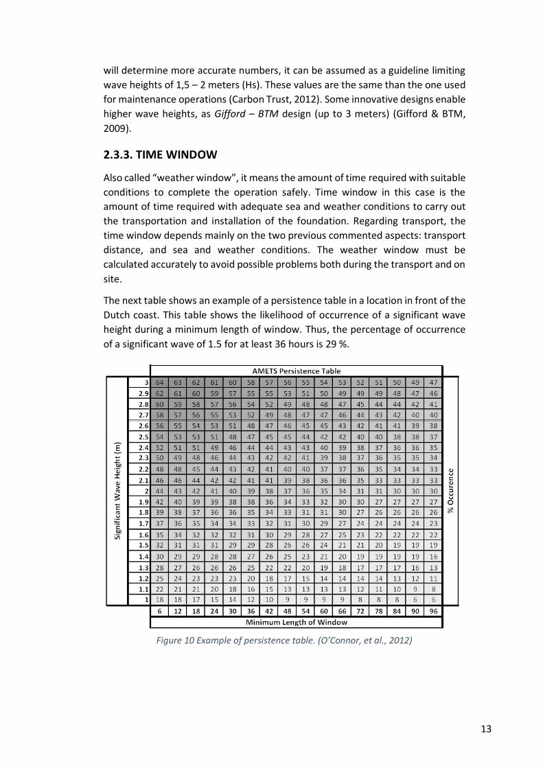
2.3.3. TIME WINDOW
Also called “weather window”, it means the amount of time required with suitable
conditions to complete the operation safely. Time window in this case is the
amount of time required with adequate sea and weather conditions to carry out
the transportation and installation of the foundation. Regarding transport, the
time window depends mainly on the two previous commented aspects: transport
distance, and sea and weather conditions. The weather window must be
calculated accurately to avoid possible problems both during the transport and on
site.
The next table shows an example of a persistence table in a location in front of the
Dutch coast. This table shows the likelihood of occurrence of a significant wave
height during a minimum length of window. Thus, the percentage of occurrence
of a significant wave of 1.5 for at least 36 hours is 29 %.
Figure 10 Example of persistence table. (O’Connor, et al., 2012)
14
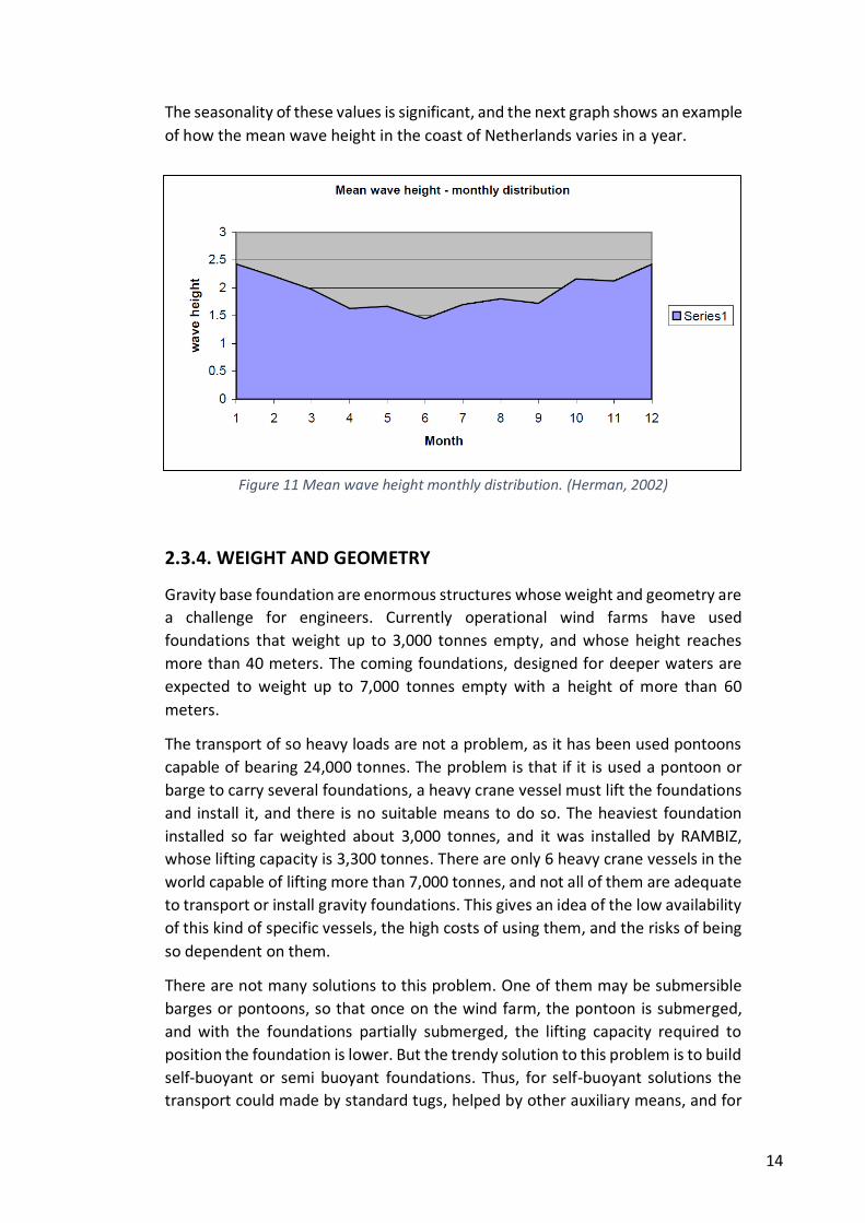
The seasonality of these values is significant, and the next graph shows an example
of how the mean wave height in the coast of Netherlands varies in a year.
2.3.4. WEIGHT AND GEOMETRY
Gravity base foundation are enormous structures whose weight and geometry are
a challenge for engineers. Currently operational wind farms have used
foundations that weight up to 3,000 tonnes empty, and whose height reaches
more than 40 meters. The coming foundations, designed for deeper waters are
expected to weight up to 7,000 tonnes empty with a height of more than 60
meters.
The transport of so heavy loads are not a problem, as it has been used pontoons
capable of bearing 24,000 tonnes. The problem is that if it is used a pontoon or
barge to carry several foundations, a heavy crane vessel must lift the foundations
and install it, and there is no suitable means to do so. The heaviest foundation
installed so far weighted about 3,000 tonnes, and it was installed by RAMBIZ,
whose lifting capacity is 3,300 tonnes. There are only 6 heavy crane vessels in the
world capable of lifting more than 7,000 tonnes, and not all of them are adequate
to transport or install gravity foundations. This gives an idea of the low availability
of this kind of specific vessels, the high costs of using them, and the risks of being
so dependent on them.
There are not many solutions to this problem. One of them may be submersible
barges or pontoons, so that once on the wind farm, the pontoon is submerged,
and with the foundations partially submerged, the lifting capacity required to
position the foundation is lower. But the trendy solution to this problem is to build
self-buoyant or semi buoyant foundations. Thus, for self-buoyant solutions the
transport could made by standard tugs, helped by other auxiliary means, and for
Figure 11 Mean wave height monthly distribution. (Herman, 2002)
15
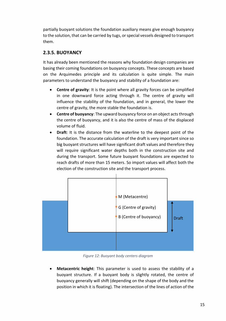
Figure 12: Buoyant body centers diagram
partially buoyant solutions the foundation auxiliary means give enough buoyancy
to the solution, that can be carried by tugs, or special vessels designed to transport
them.
2.3.5. BUOYANCY
It has already been mentioned the reasons why foundation design companies are
basing their coming foundations on buoyancy concepts. These concepts are based
on the Arquimedes principle and its calculation is quite simple. The main
parameters to understand the buoyancy and stability of a foundation are:
Centre of gravity: It is the point where all gravity forces can be simplified
in one downward force acting through it. The centre of gravity will
influence the stability of the foundation, and in general, the lower the
centre of gravity, the more stable the foundation is.
Centre of buoyancy: The upward buoyancy force on an object acts through
the centre of buoyancy, and it is also the centre of mass of the displaced
volume of fluid.
Draft: It is the distance from the waterline to the deepest point of the
foundation. The accurate calculation of the draft is very important since so
big buoyant structures will have significant draft values and therefore they
will require significant water depths both in the construction site and
during the transport. Some future buoyant foundations are expected to
reach drafts of more than 15 meters. So import values will affect both the
election of the construction site and the transport process.
Metacentric height: This parameter is used to assess the stability of a
buoyant structure. If a buoyant body is slightly rotated, the centre of
buoyancy generally will shift (depending on the shape of the body and the
position in which it is floating). The intersection of the lines of action of the
G (Centre of gravity)
B (Centre of buoyancy)
M (Metacentre)
Draft
16
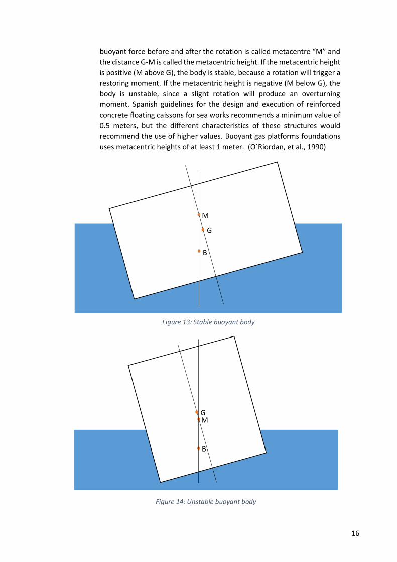
Figure 14: Unstable buoyant body
buoyant force before and after the rotation is called metacentre “M” and
the distance G-M is called the metacentric height. If the metacentric height
is positive (M above G), the body is stable, because a rotation will trigger a
restoring moment. If the metacentric height is negative (M below G), the
body is unstable, since a slight rotation will produce an overturning
moment. Spanish guidelines for the design and execution of reinforced
concrete floating caissons for sea works recommends a minimum value of
0.5 meters, but the different characteristics of these structures would
recommend the use of higher values. Buoyant gas platforms foundations
uses metacentric heights of at least 1 meter. (O´Riordan, et al., 1990)
G
B
M
G
B
M
Figure 13: Stable buoyant body
17
Moment of inertia on the water plane: The moment of inertia of the
waterplane about the centreline (IWPAXX), is a measure of roll resistance,
and it is also an important consideration for small-angle stability.
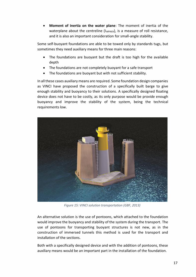
Some self-buoyant foundations are able to be towed only by standards tugs, but
sometimes they need auxiliary means for three main reasons:
The foundations are buoyant but the draft is too high for the available
depth
The foundations are not completely buoyant for a safe transport
The foundations are buoyant but with not sufficient stability.
In all these cases auxiliary means are required. Some foundation design companies
as VINCI have proposed the construction of a specifically built barge to give
enough stability and buoyancy to their solutions. A specifically designed floating
device does not have to be costly, as its only purpose would be provide enough
buoyancy and improve the stability of the system, being the technical
requirements low.
An alternative solution is the use of pontoons, which attached to the foundation
would improve the buoyancy and stability of the system during the transport. The
use of pontoons for transporting buoyant structures is not new, as in the
construction of immersed tunnels this method is used for the transport and
installation of the sections.
Both with a specifically designed device and with the addition of pontoons, these
auxiliary means would be an important part in the installation of the foundation.
Figure 15: VINCI solution transportation (GBF, 2013)
18
2.3.6. STORAGE
In case of bad weather, some foundations have the possibility of being safely
stored in the sea and refloated later. The technique has already been used in the
construction of ports with floating caissons. This feature has some advantages:
The foundation could be stored in the sea close to the construction yard
for several reasons: the transportation is not possible for bad conditions,
transport vessels are not available, facilities problems, etc. As the
foundation is stored in the sea, the construction yard is not occupied so
the construction is not interrupted.
The foundation could be stored in the sea during the transport phase for
bad weather / sea conditions or technical problems during the trip.
The foundation could be stored in the wind farm before installing for bad
weather / sea conditions or technical problems.
Having the possibility of leave the foundation on the seabed temporarily could
reduce the time window required, the risks, the waiting times, etc. However, this
is not an easy operation so it has to be considered carefully.
2.4. TRANSPORT MEANS
The size and weight of the foundations to be transported makes the transport
means a limiting factor for the whole project and an important aspect to consider
and plan. The most important transport means are:
SPMTs: Self-propelled modular transporter. They are used to transport the
foundation on shore from the construction yard to the quay or the
launching area. They consist of a platform vehicle with a large array of
wheels commonly used for transporting massive objects in construction.
Barges and pontoons: They have been frequently used for transporting
several foundation simultaneously and basically they are floating devices
that are able to carry heavy loads. They may be self-propelled or not. In
this latter case they are towed by tugs to the wind farm. The capacity of
these means is not a constraint as they have already been used pontoons
capable of carrying 24,000 tonnes (“Giant 4”). Some pontoons are semi-
submersible to facilitate the unloading of the foundations.
Heavy lift vessels: They have been used both for transporting and installing
foundations. Only two vessels have carried out the tasks in all the relevant
projects so far: EIDE Barge 5 (1,450 tonnes of lifting capacity) and RAMBIZ
(3,300 tonnes of lifting capacity), what gives an idea of the so low
availability of these vessels. This low availability makes them means of
transport costly and risky.
Auxiliary means for buoyant solutions: They consist of simple floating
devices whose purpose is only to increase the buoyancy of a foundation or
19
improve the stability of a buoyant foundations. They may be pontoons
attached to the foundation or specifically built devices.
20
3. SEABED PREPARATION
3.1. INTRODUCTION
Gravity base foundations are the type of foundations that require the most
important seabed preparation as they are heavier and they transfer the loads
directly to the seabed surface. The main objectives of this process are:
Obtain sufficient bearing capacity in the seabed.
Level the seabed in order to ensure that the turbine will stand perfectly
vertical.
Seabed preparation is one of the main marine operations to install a gravity base
foundation. The site investigation necessary and the enormous dimensions of the
foundations (some gravity bases require gravel beds up to the size of a soccer
pitch) trigger significant costs. This is the reason why some innovative designs
enable less seabed preparation, even avoid it.
In this chapter it will be explained the most commonly used procedures to prepare
the seabed, the main aspects of seabed preparation, and the means required.
3.2. SEABED PREPARATION PROCEDURES
3.2.1. STANDARD PROCEDURE
In all the operational wind farms the procedure used to prepare the seabed has
been practically the same, and it is based in two phases:
Dredging
The first step is dredging the first layer of material, usually clay or loose sand. Thus,
the surface of the seabed is removed until a level where undisturbed soil is found.
In some projects, the excavation was performed in two steps, bulk dredging and a
final accurate dredging.
The equipment used so far has been predominantly large back-hoe excavators
aboard barges and split hopper barges for loading the material excavated. It also
has been used hopper dredgers in some projects, which are more suitable for
deeper waters.
If the material excavated is adequate for fill in the foundations in the installation
phase, it may be disposed nearby in order to use it later, if not, it must be disposed
at sea in registered sites.
The thickness of the layer to be removed varies in each project (it depends on the
bathymetry, lithology, morphology, geotechnical properties, etc.) and it would
ranges from 0.5 to more than 10 meters.
21
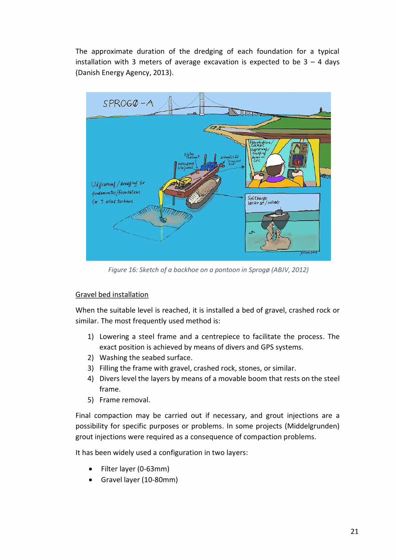
The approximate duration of the dredging of each foundation for a typical
installation with 3 meters of average excavation is expected to be 3 – 4 days
(Danish Energy Agency, 2013).
Gravel bed installation
When the suitable level is reached, it is installed a bed of gravel, crashed rock or
similar. The most frequently used method is:
1) Lowering a steel frame and a centrepiece to facilitate the process. The
exact position is achieved by means of divers and GPS systems.
2) Washing the seabed surface.
3) Filling the frame with gravel, crashed rock, stones, or similar.
4) Divers level the layers by means of a movable boom that rests on the steel
frame.
5) Frame removal.
Final compaction may be carried out if necessary, and grout injections are a
possibility for specific purposes or problems. In some projects (Middelgrunden)
grout injections were required as a consequence of compaction problems.
It has been widely used a configuration in two layers:
Filter layer (0-63mm)
Gravel layer (10-80mm)
Figure 16: Sketch of a backhoe on a pontoon in Sprogø (ABJV, 2012)
22
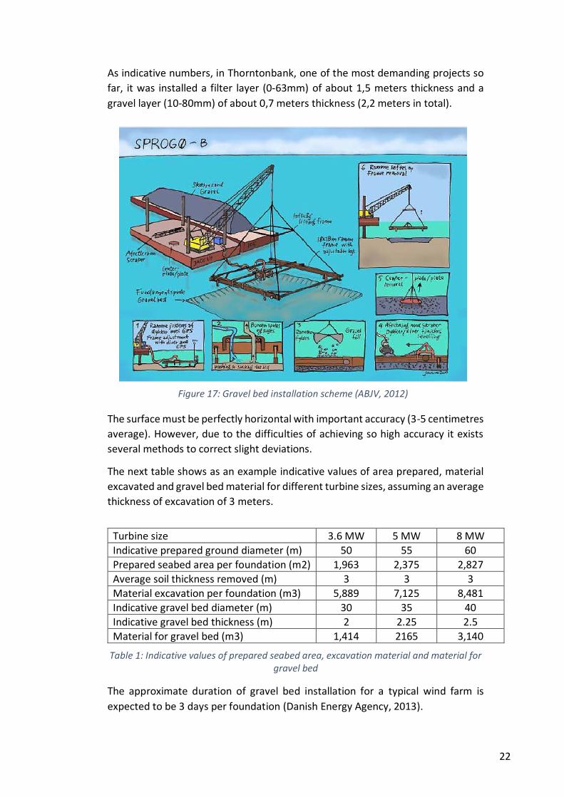
As indicative numbers, in Thorntonbank, one of the most demanding projects so
far, it was installed a filter layer (0-63mm) of about 1,5 meters thickness and a
gravel layer (10-80mm) of about 0,7 meters thickness (2,2 meters in total).
The surface must be perfectly horizontal with important accuracy (3-5 centimetres
average). However, due to the difficulties of achieving so high accuracy it exists
several methods to correct slight deviations.
The next table shows as an example indicative values of area prepared, material
excavated and gravel bed material for different turbine sizes, assuming an average
thickness of excavation of 3 meters.
Turbine size 3.6 MW 5 MW 8 MW
Indicative prepared ground diameter (m) 50 55 60
Prepared seabed area per foundation (m2) 1,963 2,375 2,827
Average soil thickness removed (m) 3 3 3
Material excavation per foundation (m3) 5,889 7,125 8,481
Indicative gravel bed diameter (m) 30 35 40
Indicative gravel bed thickness (m) 2 2.25 2.5
Material for gravel bed (m3) 1,414 2165 3,140
Table 1: Indicative values of prepared seabed area, excavation material and material for gravel bed
The approximate duration of gravel bed installation for a typical wind farm is
expected to be 3 days per foundation (Danish Energy Agency, 2013).
Figure 17: Gravel bed installation scheme (ABJV, 2012)
23
3.2.2. SKIRTED FOUNDATIONS
Gravity base foundations require an important seabed preparation that rises the
costs of the project. Trying to minimize this operation and optimize the foundation
performance, the concept of skirted foundations is starting to be considered for
the coming projects.
Skirted foundations are usually circular shaped and includes a “skirt” at the
bottom, usually made of steel, that makes the base open. The foundations
penetrate partially into the seabed, increasing the bearing area. In these
structures, the load is transferred down to lower underlying layers, lateral load
capacity is improved by the skirt lateral resistance and the moment load capacity
rises. Besides the foundations resists uplift. (Ahmadi & Ghazavi, 2012).
No significant wind farms with gravity base foundations have used this concept so
far. However, it has been widely utilized in other offshore projects, as oil
platforms. Since 1970, about 30 skirted gravity structures have been installed
successfully in waters from 40 to 300 m deep.
Skirted foundations not only improve the structural performance of the
foundation, but they also minimize seabed preparation, as they accommodate
existing seabed slopes and surface sediments, and allows less demanding
properties of the first layers. Other important advantage of this concept, is that it
minimizes scour phenomenon, so scour protection is reduced as well.
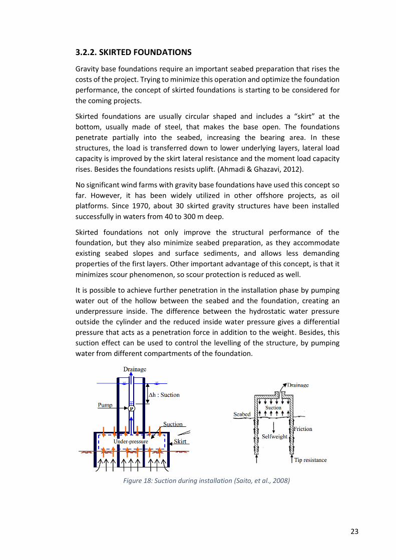
It is possible to achieve further penetration in the installation phase by pumping
water out of the hollow between the seabed and the foundation, creating an
underpressure inside. The difference between the hydrostatic water pressure
outside the cylinder and the reduced inside water pressure gives a differential
pressure that acts as a penetration force in addition to the weight. Besides, this
suction effect can be used to control the levelling of the structure, by pumping
water from different compartments of the foundation.
Figure 18: Suction during installation (Saito, et al., 2008)
24
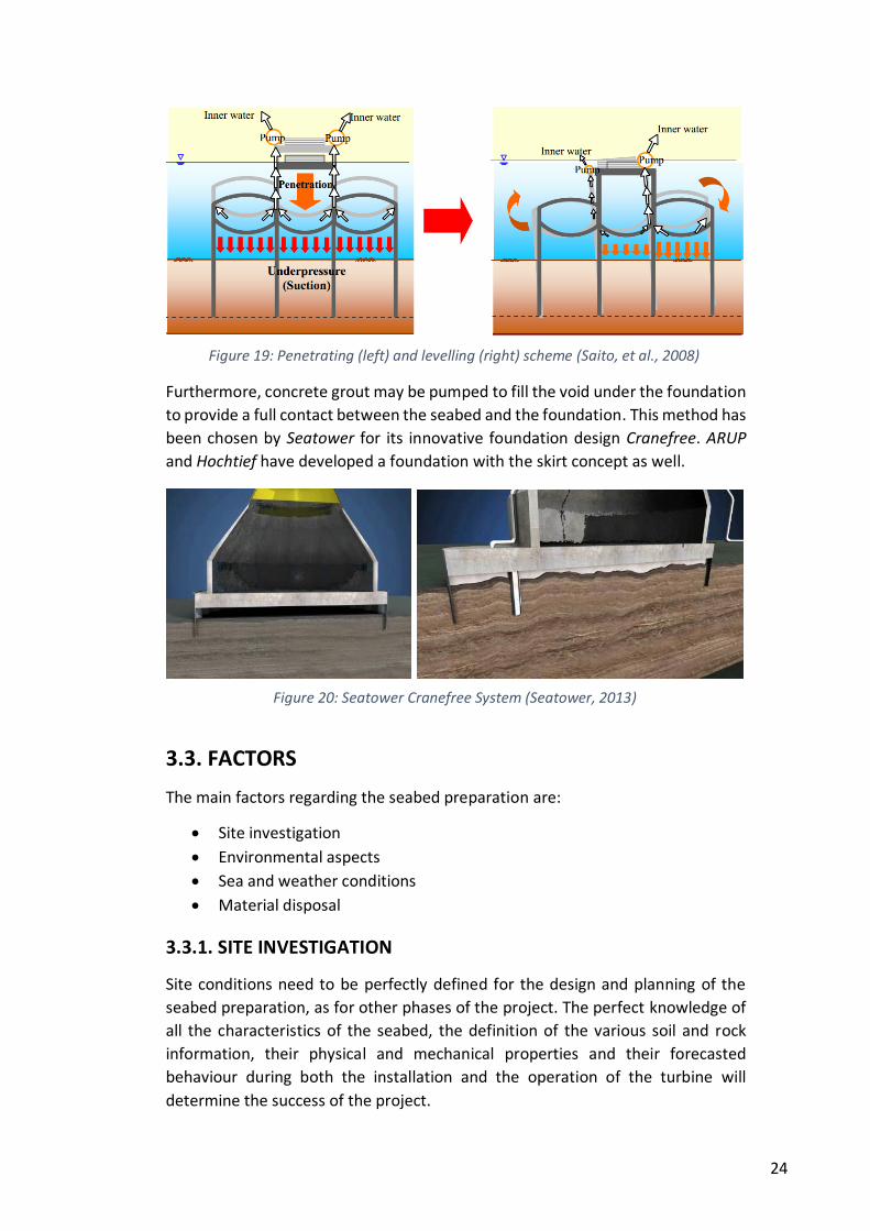
Furthermore, concrete grout may be pumped to fill the void under the foundation
to provide a full contact between the seabed and the foundation. This method has
been chosen by Seatower for its innovative foundation design Cranefree. ARUP
and Hochtief have developed a foundation with the skirt concept as well.
3.3. FACTORS
The main factors regarding the seabed preparation are:
Site investigation
Environmental aspects
Sea and weather conditions
Material disposal
3.3.1. SITE INVESTIGATION
Site conditions need to be perfectly defined for the design and planning of the
seabed preparation, as for other phases of the project. The perfect knowledge of
all the characteristics of the seabed, the definition of the various soil and rock
information, their physical and mechanical properties and their forecasted
behaviour during both the installation and the operation of the turbine will
determine the success of the project.
Figure 19: Penetrating (left) and levelling (right) scheme (Saito, et al., 2008)
Figure 20: Seatower Cranefree System (Seatower, 2013)
25
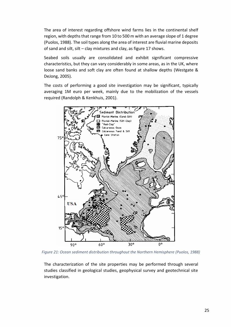
The area of interest regarding offshore wind farms lies in the continental shelf
region, with depths that range from 10 to 500 m with an average slope of 1 degree
(Puolos, 1988). The soil types along the area of interest are fluvial marine deposits
of sand and silt, silt – clay mixtures and clay, as figure 17 shows.
Seabed soils usually are consolidated and exhibit significant compressive
characteristics, but they can vary considerably in some areas, as in the UK, where
loose sand banks and soft clay are often found at shallow depths (Westgate &
DeJong, 2005).
The costs of performing a good site investigation may be significant, typically
averaging 1M euro per week, mainly due to the mobilization of the vessels
required (Randolph & Kenkhuis, 2001).
The characterization of the site properties may be performed through several
studies classified in geological studies, geophysical survey and geotechnical site
investigation.
Figure 21: Ocean sediment distribution throughout the Northern Hemisphere (Puolos, 1988)
26
Geological studies. They are based on the geological history of the area,
and aims at performing a study of the lithology and tectonic structures in
the project area as well as the bedding conditions of the soil.
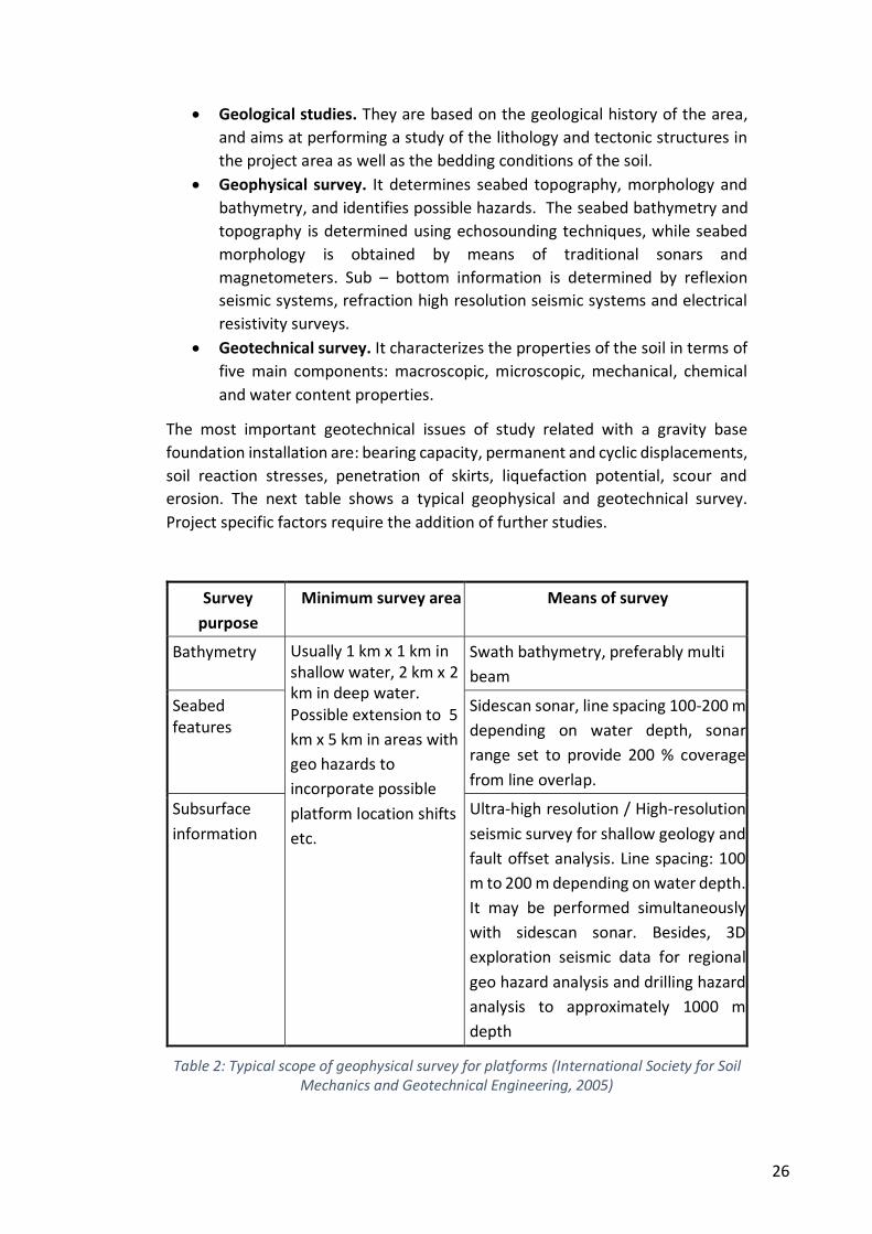
Geophysical survey. It determines seabed topography, morphology and
bathymetry, and identifies possible hazards. The seabed bathymetry and
topography is determined using echosounding techniques, while seabed
morphology is obtained by means of traditional sonars and
magnetometers. Sub – bottom information is determined by reflexion
seismic systems, refraction high resolution seismic systems and electrical
resistivity surveys.
Geotechnical survey. It characterizes the properties of the soil in terms of
five main components: macroscopic, microscopic, mechanical, chemical
and water content properties.
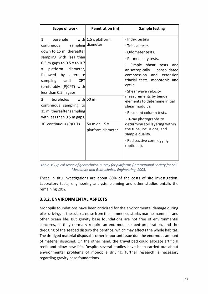
The most important geotechnical issues of study related with a gravity base
foundation installation are: bearing capacity, permanent and cyclic displacements,
soil reaction stresses, penetration of skirts, liquefaction potential, scour and
erosion. The next table shows a typical geophysical and geotechnical survey.
Project specific factors require the addition of further studies.
Survey
purpose
Minimum survey area Means of survey
Bathymetry Usually 1 km x 1 km in shallow water, 2 km x 2 km in deep water. Possible extension to 5
km x 5 km in areas with
geo hazards to
incorporate possible
platform location shifts
etc.
Swath bathymetry, preferably multi
beam
Seabed features
Sidescan sonar, line spacing 100-200 m
depending on water depth, sonar
range set to provide 200 % coverage
from line overlap.
Subsurface
information
Ultra-high resolution / High-resolution
seismic survey for shallow geology and
fault offset analysis. Line spacing: 100
m to 200 m depending on water depth.
It may be performed simultaneously
with sidescan sonar. Besides, 3D
exploration seismic data for regional
geo hazard analysis and drilling hazard
analysis to approximately 1000 m
depth
Table 2: Typical scope of geophysical survey for platforms (International Society for Soil Mechanics and Geotechnical Engineering, 2005)
27
Scope of work Penetration (m) Sample testing
1 borehole with
continuous sampling
down to 15 m, thereafter
sampling with less than
0.5 m gaps to 0.5 x to 0.7
x platform diameter,
followed by alternate
sampling and CPT
(preferably (P)CPT) with
less than 0.5 m gaps.
1.5 x platform diameter
· Index testing
· Triaxial tests
· Odometer tests.
· Permeability tests.
· Simple shear tests and anisotropically consolidated compression and extension triaxial tests, monotonic and cyclic.
· Shear wave velocity measurements by bender elements to determine initial shear modulus.
· Resonant column tests.
· X-ray photographs to determine soil layering within the tube, inclusions, and sample quality.
· Radioactive core logging (optional).
3 boreholes with
continuous sampling to
15 m, thereafter sampling
with less than 0.5 m gaps.
50 m
10 continuous (P)CPTs 50 m or 1.5 x
platform diameter
Table 3: Typical scope of geotechnical survey for platforms (International Society for Soil Mechanics and Geotechnical Engineering, 2005)
These in situ investigations are about 80% of the costs of site investigation.
Laboratory tests, engineering analysis, planning and other studies entails the
remaining 20%.
3.3.2. ENVIRONMENTAL ASPECTS
Monopile foundations have been criticized for the environmental damage during
piles driving, as the subsea noise from the hammers disturbs marine mammals and
other ocean life. But gravity base foundations are not free of environmental
concerns, as they normally require an enormous seabed preparation, and the
dredging of the seabed disturb the benthos, which may affects the whole habitat.
The dredged material disposal is other important issue due the enormous amount
of material disposed. On the other hand, the gravel bed could allocate artificial
reefs and allow new life. Despite several studies have been carried out about
environmental problems of monopile driving, further research is necessary
regarding gravity base foundations.
28
3.3.3. SEA AND WEATHER CONDITIONS
Sea and weather conditions during seabed preparation are a constraint as in all
marine operations. Thus, wave heights of 1.5 – 2 m maximum are expected to be
required, depending on the specific features of the project and the exact phase.
The use of divers for some tasks triggers the necessity of good visibility as well.
3.3.4. MATERIAL DISPOSAL
Loose sand, clay and other unsuitable material dredged range from 6,000 to
10,000 cubic meters per turbine for typical installations (in Thornton bank it was
dredge up to 90,000 m3 per foundation), so the disposal of this excavated material
is an important economic, environmental and technical issue to handle. The
dredged material in the seabed preparation normally is loaded onto split hopper
barges. The excavation required for each foundation is expected to produce
between 5 and 10 barge loads. Commonly, this material is used later as ballast of
the foundation within the structure or as scour protection, so it is disposed nearby.
If the material is not necessary for later operation, or is not suitable, it is disposed
at sea at registered disposal location.
3.4. MEANS
The enormous dimensions of the seabed preparation for the installation of gravity
base foundations makes necessary an intensive use of heavy vessels, barges and
other means. The most frequently used for this phase are:
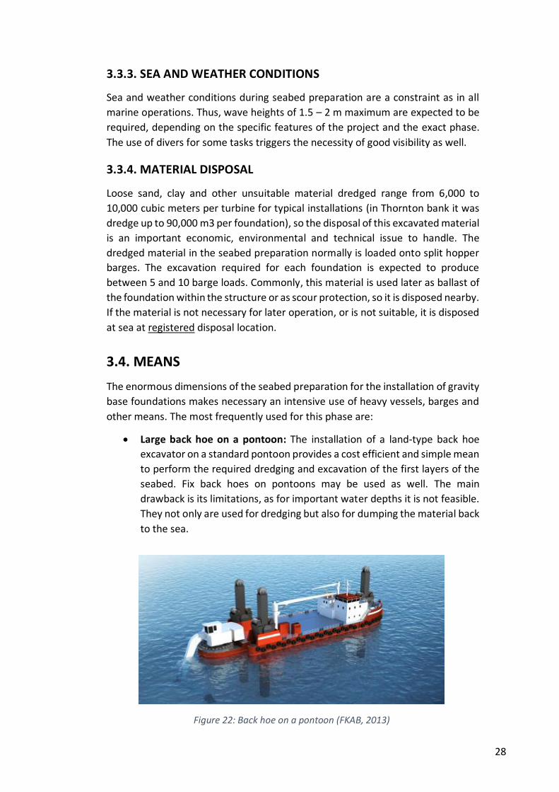
Large back hoe on a pontoon: The installation of a land-type back hoe
excavator on a standard pontoon provides a cost efficient and simple mean
to perform the required dredging and excavation of the first layers of the
seabed. Fix back hoes on pontoons may be used as well. The main
drawback is its limitations, as for important water depths it is not feasible.
They not only are used for dredging but also for dumping the material back
to the sea.
Figure 22: Back hoe on a pontoon (FKAB, 2013)
29
Dredgers: They are vessels used to excavate and remove material from the
seabed. There are many types of dredgers depending on their excavation
method. Suction dredgers are the most commonly used for this task due
to the characteristics of the first layers to remove. Regarding the disposal
of materials, in a hopper dredger the materials goes to an on-board hold
called “hopper”. If the dredger does not have this storage area, they
dispose it in other barges.
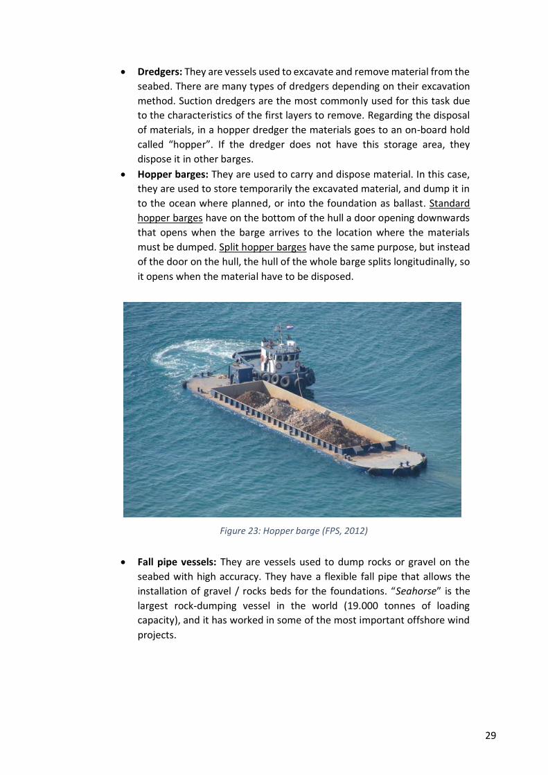
Hopper barges: They are used to carry and dispose material. In this case,
they are used to store temporarily the excavated material, and dump it in
to the ocean where planned, or into the foundation as ballast. Standard
hopper barges have on the bottom of the hull a door opening downwards
that opens when the barge arrives to the location where the materials
must be dumped. Split hopper barges have the same purpose, but instead
of the door on the hull, the hull of the whole barge splits longitudinally, so
it opens when the material have to be disposed.
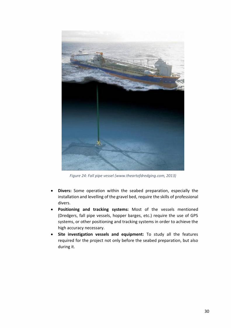
Fall pipe vessels: They are vessels used to dump rocks or gravel on the
seabed with high accuracy. They have a flexible fall pipe that allows the
installation of gravel / rocks beds for the foundations. “Seahorse” is the
largest rock-dumping vessel in the world (19.000 tonnes of loading
capacity), and it has worked in some of the most important offshore wind
projects.
Figure 23: Hopper barge (FPS, 2012)
30
Divers: Some operation within the seabed preparation, especially the
installation and levelling of the gravel bed, require the skills of professional
divers.
Positioning and tracking systems: Most of the vessels mentioned
(Dredgers, fall pipe vessels, hopper barges, etc.) require the use of GPS
systems, or other positioning and tracking systems in order to achieve the
high accuracy necessary.
Site investigation vessels and equipment: To study all the features
required for the project not only before the seabed preparation, but also
during it.
Figure 24: Fall pipe vessel (www.theartofdredging.com, 2013)
31
4. FOUNDATION INSTALLATION
4.1. INTRODUCTION
When the foundation arrives to the wind farm, and after having prepared the
seabed, it is time to install the foundation. In this operation, the foundation will
be accurately placed on the seabed and ballasted to provide weight enough to
withstand the loads. Installation is one of the most delicate phases of the project
and requires accurate techniques and procedures. The trend towards the
installation in deeper waters triggers bigger and heavier foundations that led to
the application of techniques not used so far in offshore wind farms, and the
adaptation of procedures used in gas platforms and immersed tunnels.
In this chapter it will be studied both the main procedures of installation used so
far and the applicable concepts for the near future, the main factors that affect
the installation, and the means required.
4.2. FOUNDATION INSTALLATION PROCEDURES
The installation processes will be studied subdivided in three main operations:
Positioning
Hoisting and lowering
Fillings
4.2.1. POSITIONING
The first step is to place the foundation above its final location. To do so, all the
means required are equipped with accurate GPS systems and other positioning
and tracking devices. Divers and cameras may be used to monitor the operation.
4.2.2. HOISTING AND LOWERING
This is the main and most demanding operation. Hoisting (if required) and
lowering the foundation depends directly on the typology of transportation used,
and on the foundation features. Thus, this operation will be different with each
transport method:
a) Foundations transported by barges or pontoons
As it has been analysed in the transport chapter, one important type of foundation
transport is in groups, on flat-top barges or pontoons. With this method, the
foundation have to be picked up by a heavy crane vessel, and then this vessel will
lower the foundation to the seabed.
The hoisting operation is the bottleneck of the whole process, as a heavy lift vessel
must hoist a foundation that may weigh up to 7,000 tonnes empty, and only half
32
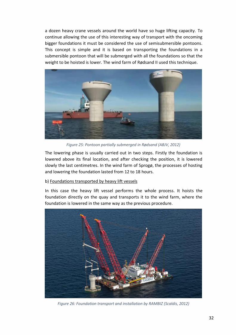
a dozen heavy crane vessels around the world have so huge lifting capacity. To
continue allowing the use of this interesting way of transport with the oncoming
bigger foundations it must be considered the use of semisubmersible pontoons.
This concept is simple and it is based on transporting the foundations in a
submersible pontoon that will be submerged with all the foundations so that the
weight to be hoisted is lower. The wind farm of Rødsand II used this technique.
The lowering phase is usually carried out in two steps. Firstly the foundation is
lowered above its final location, and after checking the position, it is lowered
slowly the last centimetres. In the wind farm of Sprogø, the processes of hosting
and lowering the foundation lasted from 12 to 18 hours.
b) Foundations transported by heavy lift vessels
In this case the heavy lift vessel performs the whole process. It hoists the
foundation directly on the quay and transports it to the wind farm, where the
foundation is lowered in the same way as the previous procedure.
Figure 25: Pontoon partially submerged in Rødsand (ABJV, 2012)
Figure 26: Foundation transport and installation by RAMBIZ (Scaldis, 2012)

33
c) Buoyant foundations
The installation of buoyant foundation is a challenge for engineers. The process is
less dependent on unavailable huge means but, on the other hand, it is a
technically more difficult procedure. No operational wind farms have used this
procedure yet, but the trend is towards buoyant solutions and the technique has
already been used in the construction of immersed tunnels or gravity foundations
for oil and gas platforms.
There are two basic operations in the lowering of a buoyant solution: flooding or
ballasting (usually with water), and the position control. Regarding the former,
buoyant foundations have compartments uniformly distributed that would be
flooded symmetrically. As the foundation weight rises, it descends onto the sea
bed. The position is controlled by means of towing vessels with the help of
anchors, or by means of pontoons.
Figure 27: Simulation of foundation lowering controlled by three vessels (Seatower, 2012)
Figure 28: Immersed tunnel installed by pontoons (www.struktonciviel.com)
34
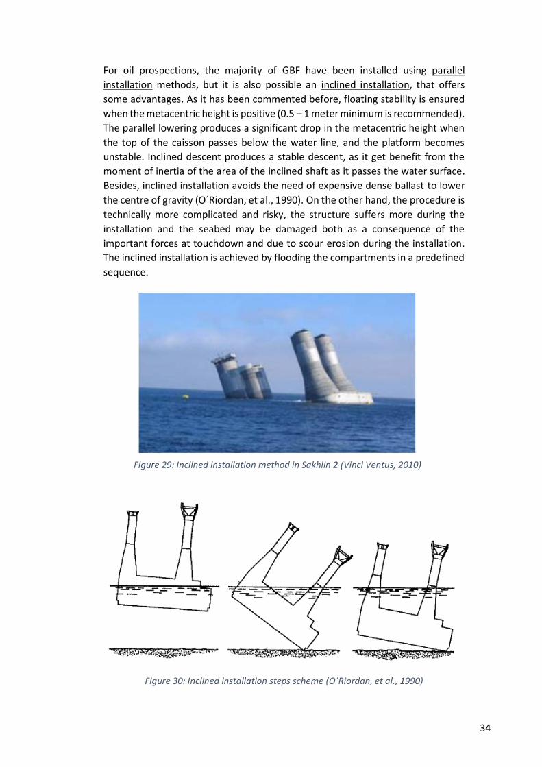
For oil prospections, the majority of GBF have been installed using parallel
installation methods, but it is also possible an inclined installation, that offers
some advantages. As it has been commented before, floating stability is ensured
when the metacentric height is positive (0.5 – 1 meter minimum is recommended).
The parallel lowering produces a significant drop in the metacentric height when
the top of the caisson passes below the water line, and the platform becomes
unstable. Inclined descent produces a stable descent, as it get benefit from the
moment of inertia of the area of the inclined shaft as it passes the water surface.
Besides, inclined installation avoids the need of expensive dense ballast to lower
the centre of gravity (O´Riordan, et al., 1990). On the other hand, the procedure is
technically more complicated and risky, the structure suffers more during the
installation and the seabed may be damaged both as a consequence of the
important forces at touchdown and due to scour erosion during the installation.
The inclined installation is achieved by flooding the compartments in a predefined
sequence.
Figure 29: Inclined installation method in Sakhlin 2 (Vinci Ventus, 2010)
Figure 30: Inclined installation steps scheme (O´Riordan, et al., 1990)
35
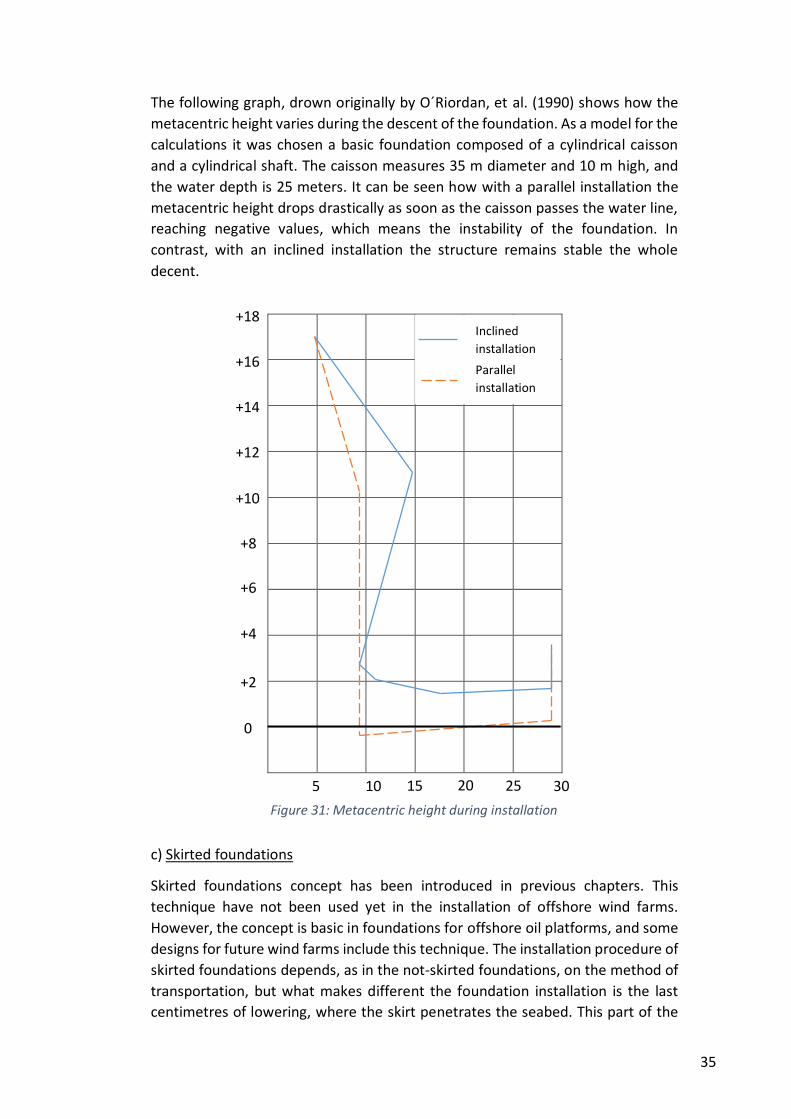
The following graph, drown originally by O´Riordan, et al. (1990) shows how the
metacentric height varies during the descent of the foundation. As a model for the
calculations it was chosen a basic foundation composed of a cylindrical caisson
and a cylindrical shaft. The caisson measures 35 m diameter and 10 m high, and
the water depth is 25 meters. It can be seen how with a parallel installation the
metacentric height drops drastically as soon as the caisson passes the water line,
reaching negative values, which means the instability of the foundation. In
contrast, with an inclined installation the structure remains stable the whole
decent.
c) Skirted foundations
Skirted foundations concept has been introduced in previous chapters. This
technique have not been used yet in the installation of offshore wind farms.
However, the concept is basic in foundations for offshore oil platforms, and some
designs for future wind farms include this technique. The installation procedure of
skirted foundations depends, as in the not-skirted foundations, on the method of
transportation, but what makes different the foundation installation is the last
centimetres of lowering, where the skirt penetrates the seabed. This part of the
+18
+16
+14
+12
+10
+8
+6
+4
+2
0
5 10 15 20 25 30
Figure 31: Metacentric height during installation
Inclined
installation
Parallel
installation
36
installation is the most delicate, as several factors must be monitored and
controlled: penetration rate, inclination, liquefaction phenomena, etc.
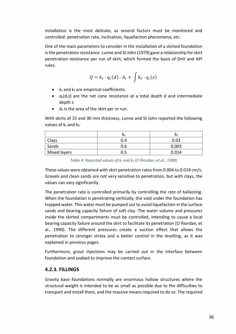
One of the main parameters to consider in the installation of a skirted foundation
is the penetration resistance. Lunne and St John (1979) gave a relationship for skirt
penetration resistance per run of skirt, which formed the basis of DnV and API
rules:
𝑄 = 𝑘𝑡 · 𝑞𝑐(𝑑) · 𝐴𝑡 + ∫ 𝑘𝑓 · 𝑞𝑐(𝑧)
kt and kf are empirical coefficients.
qc(d,z) are the net cone resistance at a total depth d and intermediate
depth z.
At is the area of the skirt per m run.
With skirts of 15 and 30 mm thickness, Lunne and St John reported the following
values of kt and kf:
kt kf
Clays 0.4 0.03
Sands 0.6 0.003
Mixed layers 0.5 0.014
Table 4: Reported values of kt and kf (O´Riordan, et al., 1990)
These values were obtained with skirt penetration rates from 0.004 to 0.019 cm/s.
Gravels and clean sands are not very sensitive to penetration, but with clays, the
values can vary significantly.
The penetration rate is controlled primarily by controlling the rate of ballasting.
When the foundation is penetrating vertically, the void under the foundation has
trapped water. This water must be pumped out to avoid liquefaction in the surface
sands and bearing capacity failure of soft clay. The water volume and pressures
inside the skirted compartments must be controlled, intending to cause a local
bearing capacity failure around the skirt to facilitate its penetration (O´Riordan, et
al., 1990). The different pressures create a suction effect that allows the
penetration to stronger strata and a better control in the levelling, as it was
explained in previous pages.
Furthermore, grout injections may be carried out in the interface between
foundation and seabed to improve the contact surface.
4.2.3. FILLINGS
Gravity base foundations normally are enormous hollow structures where the
structural weight is intended to be as small as possible due to the difficulties to
transport and install them, and the massive means required to do so. The required
37
final weight to withstand the loads is achieved by ballasting the foundation. There
are two main types of fillings:
Backfilling: After the foundation is placed, the foundation pit dredged in
the seabed preparation phase is filled. The material used is usually sand or
gravel, sometimes from the previous excavation, but it also has been used
rocky material. Some designs have a base plate so that the backfill material
covers this plate and gives the foundation uplift resistance.
Infilling: The hollow shaft (and compartments in some designs) are filled
as well. Normally the material used is sand, gravel or rocky material. In the
case of using sand, it has to be re-mixed in the vessel with water so that it
can be pumped into the foundation. However, in Kårehamn, an under
construction offshore wind farm, it is being used crude iron ore, with
higher density than gravel or rock. In oil platforms foundations it is not rare
the use of dense ballast in order to lower the centre of gravity for stability
reasons during the installation
4.3. FACTORS
4.3.1. SEA AND WEATHER CONDITIONS
As in the transport phase, sea and weather conditions are of vital importance in
the installation of the foundations, especially in the lowering phase. The main
parameters to characterise sea and weather conditions are the same than in
transportation: wind speed, visibility, wave height, wave period, tidal currents,
snow and ice. Underwater visibility may be necessary as well in some phases of
the installation.
As some examples, in the Nysted I wind farm, the heavy lift vessel “EIDE barge 5”
worked with 0.8 meters of wave height (Vølund, 2005). However, better anchors
and winches, and other installation vessels could allow severer conditions.
Furthermore, the important company COWI A/S have reported that the limiting
wave from previous experiences in the installation of foundations have been Hs <
1 – 1.5 meters. Strabag, a company that has designed an interesting solution that
weights up to 7,500 tonnes completely assembled and can be placed in water
depths of about 40 meters, says that using a DP2 positioning system and a heave
compensation in the winch system they are able to install the foundation with a
sea state of 2.5 meters of wave height (significant), what seems to be quite
optimistic. Gifford design allows significant wave heights up to 1.25 meters
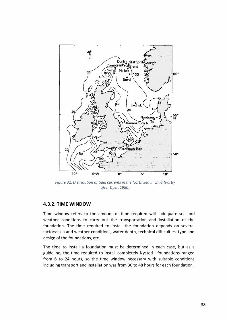
(Gifford, 2009). As for the tidal currents, the values allowed for the lowering have
to be considered carefully, as the positioning of the foundation on the seabed is a
critical operation and high accuracy is required. The next figure shows the
distribution of tidal currents in the North Sea, one of the most interesting areas in
Europe for the implementation of offshore wind farms.
38
4.3.2. TIME WINDOW
Time window refers to the amount of time required with adequate sea and
weather conditions to carry out the transportation and installation of the
foundation. The time required to install the foundation depends on several
factors: sea and weather conditions, water depth, technical difficulties, type and
design of the foundations, etc.
The time to install a foundation must be determined in each case, but as a
guideline, the time required to install completely Nysted I foundations ranged
from 6 to 24 hours, so the time window necessary with suitable conditions
including transport and installation was from 30 to 48 hours for each foundation.
Figure 32: Distribution of tidal currents in the North Sea in cm/s (Partly after Dyer, 1980)
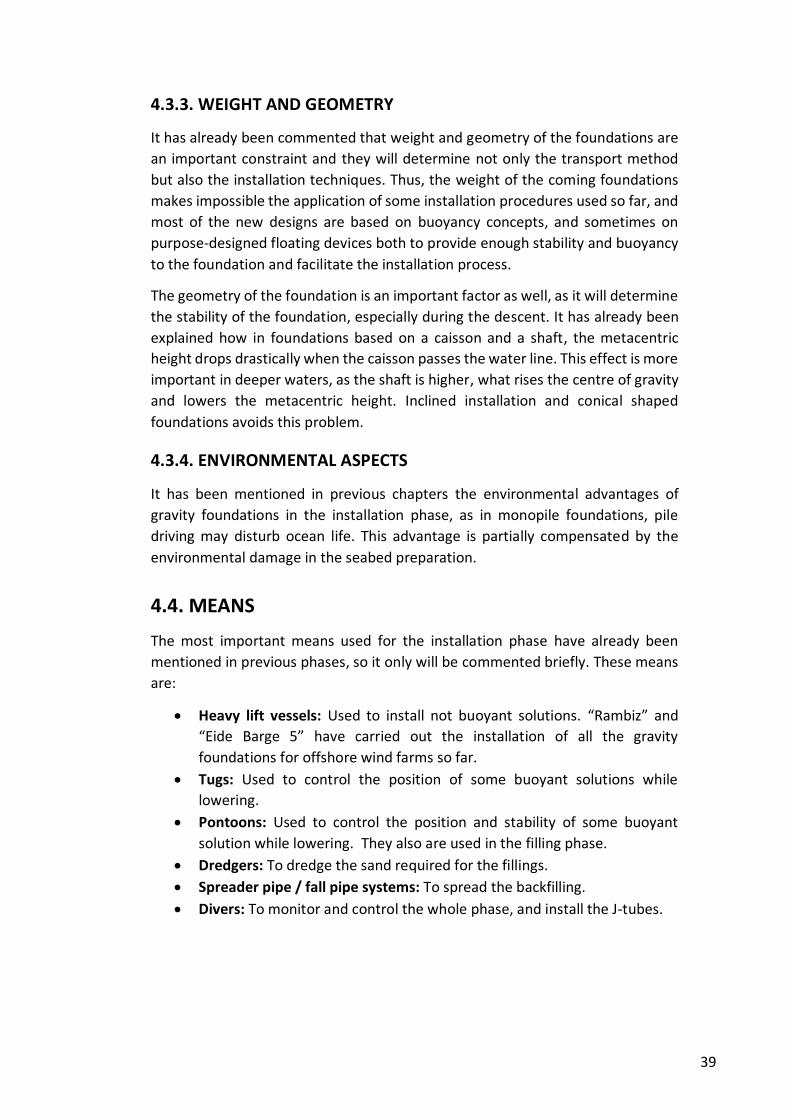
39
4.3.3. WEIGHT AND GEOMETRY
It has already been commented that weight and geometry of the foundations are
an important constraint and they will determine not only the transport method
but also the installation techniques. Thus, the weight of the coming foundations
makes impossible the application of some installation procedures used so far, and
most of the new designs are based on buoyancy concepts, and sometimes on
purpose-designed floating devices both to provide enough stability and buoyancy
to the foundation and facilitate the installation process.
The geometry of the foundation is an important factor as well, as it will determine
the stability of the foundation, especially during the descent. It has already been
explained how in foundations based on a caisson and a shaft, the metacentric
height drops drastically when the caisson passes the water line. This effect is more
important in deeper waters, as the shaft is higher, what rises the centre of gravity
and lowers the metacentric height. Inclined installation and conical shaped
foundations avoids this problem.
4.3.4. ENVIRONMENTAL ASPECTS
It has been mentioned in previous chapters the environmental advantages of
gravity foundations in the installation phase, as in monopile foundations, pile
driving may disturb ocean life. This advantage is partially compensated by the
environmental damage in the seabed preparation.
4.4. MEANS
The most important means used for the installation phase have already been
mentioned in previous phases, so it only will be commented briefly. These means
are:
Heavy lift vessels: Used to install not buoyant solutions. “Rambiz” and
“Eide Barge 5” have carried out the installation of all the gravity
foundations for offshore wind farms so far.
Tugs: Used to control the position of some buoyant solutions while
lowering.
Pontoons: Used to control the position and stability of some buoyant
solution while lowering. They also are used in the filling phase.
Dredgers: To dredge the sand required for the fillings.
Spreader pipe / fall pipe systems: To spread the backfilling.
Divers: To monitor and control the whole phase, and install the J-tubes.
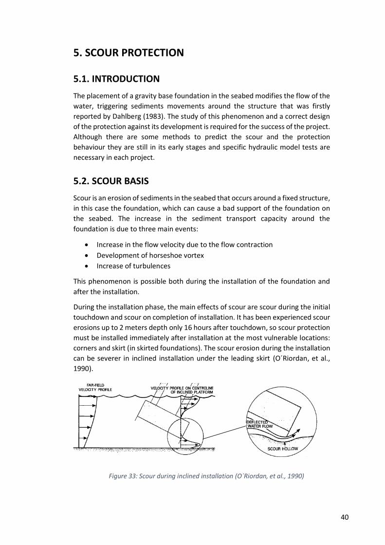
40
5. SCOUR PROTECTION
5.1. INTRODUCTION
The placement of a gravity base foundation in the seabed modifies the flow of the
water, triggering sediments movements around the structure that was firstly
reported by Dahlberg (1983). The study of this phenomenon and a correct design
of the protection against its development is required for the success of the project.
Although there are some methods to predict the scour and the protection
behaviour they are still in its early stages and specific hydraulic model tests are
necessary in each project.
5.2. SCOUR BASIS
Scour is an erosion of sediments in the seabed that occurs around a fixed structure,
in this case the foundation, which can cause a bad support of the foundation on
the seabed. The increase in the sediment transport capacity around the
foundation is due to three main events:
Increase in the flow velocity due to the flow contraction
Development of horseshoe vortex
Increase of turbulences
This phenomenon is possible both during the installation of the foundation and
after the installation.
During the installation phase, the main effects of scour are scour during the initial
touchdown and scour on completion of installation. It has been experienced scour
erosions up to 2 meters depth only 16 hours after touchdown, so scour protection
must be installed immediately after installation at the most vulnerable locations:
corners and skirt (in skirted foundations). The scour erosion during the installation
can be severer in inclined installation under the leading skirt (O´Riordan, et al.,
1990).
Figure 33: Scour during inclined installation (O´Riordan, et al., 1990)
41
When scour is considered as a possible issue, the next step to assess the scour
hazard is the prediction of the scour depth. In gravity base foundations, the scour
event is related with the diameter (or length of side) of the foundation (Dc) and
the height above the sea level (hc). The geometry of the foundation is also very
important (Whitehouse, 2011).
There are many predictions of scour depth. Rudolph et al. (2005) proposed a basic
formula for a first estimation of the maximum scour depth:
𝑆𝑚𝑎𝑥 = 𝐾 · ℎ𝑐
Where K is a dimensionless coefficient ranging from 0.2 to 2.
However, the process is so complex that predictions are not feasible enough, and
normally specific hydraulic model tests are required to assess the scour in the
project conditions for the designed foundation, and test the scour protection.
Figure 34: Velocity amplification around a square foundation (O´Riordan, et al., 1990)
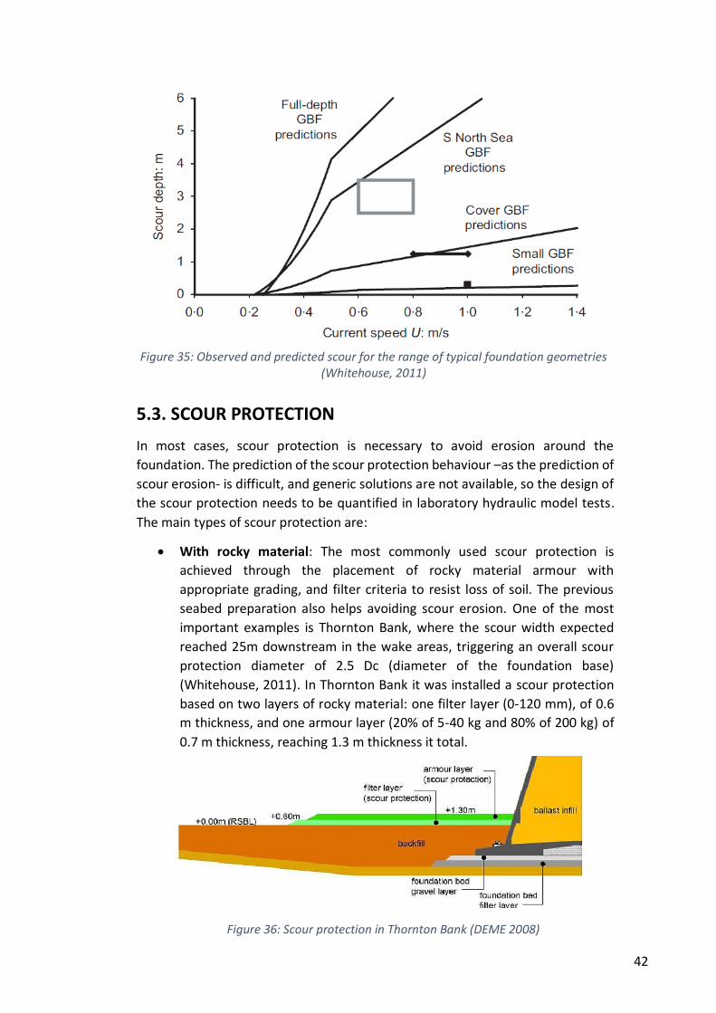
42
5.3. SCOUR PROTECTION
In most cases, scour protection is necessary to avoid erosion around the
foundation. The prediction of the scour protection behaviour –as the prediction of
scour erosion- is difficult, and generic solutions are not available, so the design of
the scour protection needs to be quantified in laboratory hydraulic model tests.
The main types of scour protection are:
With rocky material: The most commonly used scour protection is
achieved through the placement of rocky material armour with
appropriate grading, and filter criteria to resist loss of soil. The previous
seabed preparation also helps avoiding scour erosion. One of the most
important examples is Thornton Bank, where the scour width expected
reached 25m downstream in the wake areas, triggering an overall scour
protection diameter of 2.5 Dc (diameter of the foundation base)
(Whitehouse, 2011). In Thornton Bank it was installed a scour protection
based on two layers of rocky material: one filter layer (0-120 mm), of 0.6
m thickness, and one armour layer (20% of 5-40 kg and 80% of 200 kg) of
0.7 m thickness, reaching 1.3 m thickness it total.
Figure 35: Observed and predicted scour for the range of typical foundation geometries (Whitehouse, 2011)
Figure 36: Scour protection in Thornton Bank (DEME 2008)
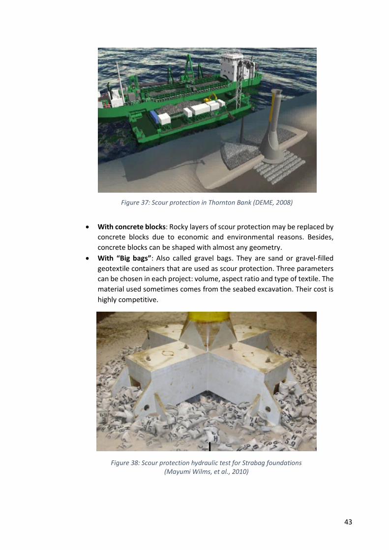
43
With concrete blocks: Rocky layers of scour protection may be replaced by
concrete blocks due to economic and environmental reasons. Besides,
concrete blocks can be shaped with almost any geometry.
With “Big bags”: Also called gravel bags. They are sand or gravel-filled
geotextile containers that are used as scour protection. Three parameters
can be chosen in each project: volume, aspect ratio and type of textile. The
material used sometimes comes from the seabed excavation. Their cost is
highly competitive.
Figure 37: Scour protection in Thornton Bank (DEME, 2008)
Figure 38: Scour protection hydraulic test for Strabag foundations (Mayumi Wilms, et al., 2010)
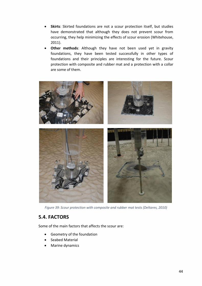
44
Skirts: Skirted foundations are not a scour protection itself, but studies
have demonstrated that although they does not prevent scour from
occurring, they help minimizing the effects of scour erosion (Whitehouse,
2011).
Other methods: Although they have not been used yet in gravity
foundations, they have been tested successfully in other types of
foundations and their principles are interesting for the future. Scour
protection with composite and rubber mat and a protection with a collar
are some of them.
5.4. FACTORS
Some of the main factors that affects the scour are:
Geometry of the foundation
Seabed Material
Marine dynamics
Figure 39: Scour protection with composite and rubber mat tests (Deltares, 2010)
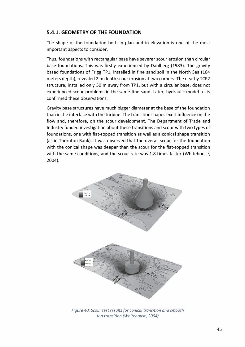
45
5.4.1. GEOMETRY OF THE FOUNDATION
The shape of the foundation both in plan and in elevation is one of the most
important aspects to consider.
Thus, foundations with rectangular base have severer scour erosion than circular
base foundations. This was firstly experienced by Dahlberg (1983). The gravity
based foundations of Frigg TP1, installed in fine sand soil in the North Sea (104
meters depth), revealed 2 m depth scour erosion at two corners. The nearby TCP2
structure, installed only 50 m away from TP1, but with a circular base, does not
experienced scour problems in the same fine sand. Later, hydraulic model tests
confirmed these observations.
Gravity base structures have much bigger diameter at the base of the foundation
than in the interface with the turbine. The transition shapes exert influence on the
flow and, therefore, on the scour development. The Department of Trade and
Industry funded investigation about these transitions and scour with two types of
foundations, one with flat-topped transition as well as a conical shape transition
(as in Thornton Bank). It was observed that the overall scour for the foundation
with the conical shape was deeper than the scour for the flat-topped transition
with the same conditions, and the scour rate was 1.8 times faster (Whitehouse,
2004).
Figure 40: Scour test results for conical transition and smooth
top transition (Whitehouse, 2004)
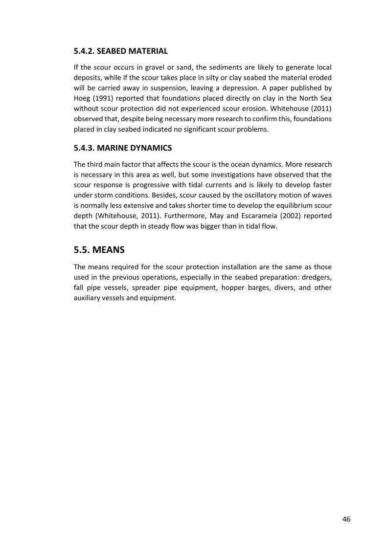
46
5.4.2. SEABED MATERIAL
If the scour occurs in gravel or sand, the sediments are likely to generate local
deposits, while if the scour takes place in silty or clay seabed the material eroded
will be carried away in suspension, leaving a depression. A paper published by
Hoeg (1991) reported that foundations placed directly on clay in the North Sea
without scour protection did not experienced scour erosion. Whitehouse (2011)
observed that, despite being necessary more research to confirm this, foundations
placed in clay seabed indicated no significant scour problems.
5.4.3. MARINE DYNAMICS
The third main factor that affects the scour is the ocean dynamics. More research
is necessary in this area as well, but some investigations have observed that the
scour response is progressive with tidal currents and is likely to develop faster
under storm conditions. Besides, scour caused by the oscillatory motion of waves
is normally less extensive and takes shorter time to develop the equilibrium scour
depth (Whitehouse, 2011). Furthermore, May and Escarameia (2002) reported
that the scour depth in steady flow was bigger than in tidal flow.
5.5. MEANS
The means required for the scour protection installation are the same as those
used in the previous operations, especially in the seabed preparation: dredgers,
fall pipe vessels, spreader pipe equipment, hopper barges, divers, and other
auxiliary vessels and equipment.
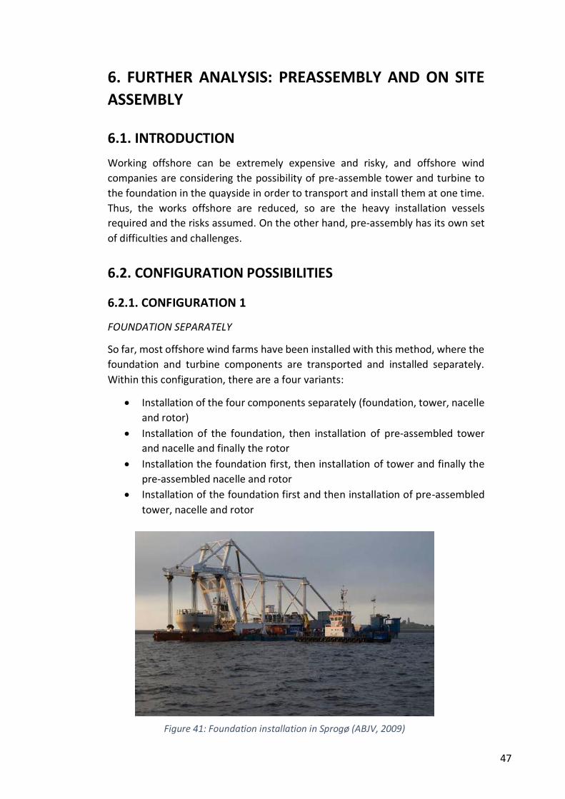
47
6. FURTHER ANALYSIS: PREASSEMBLY AND ON SITE
ASSEMBLY
6.1. INTRODUCTION
Working offshore can be extremely expensive and risky, and offshore wind
companies are considering the possibility of pre-assemble tower and turbine to
the foundation in the quayside in order to transport and install them at one time.
Thus, the works offshore are reduced, so are the heavy installation vessels
required and the risks assumed. On the other hand, pre-assembly has its own set
of difficulties and challenges.
6.2. CONFIGURATION POSSIBILITIES
6.2.1. CONFIGURATION 1
FOUNDATION SEPARATELY
So far, most offshore wind farms have been installed with this method, where the
foundation and turbine components are transported and installed separately.
Within this configuration, there are a four variants:
Installation of the four components separately (foundation, tower, nacelle
and rotor)
Installation of the foundation, then installation of pre-assembled tower
and nacelle and finally the rotor
Installation the foundation first, then installation of tower and finally the
pre-assembled nacelle and rotor
Installation of the foundation first and then installation of pre-assembled
tower, nacelle and rotor
Figure 41: Foundation installation in Sprogø (ABJV, 2009)
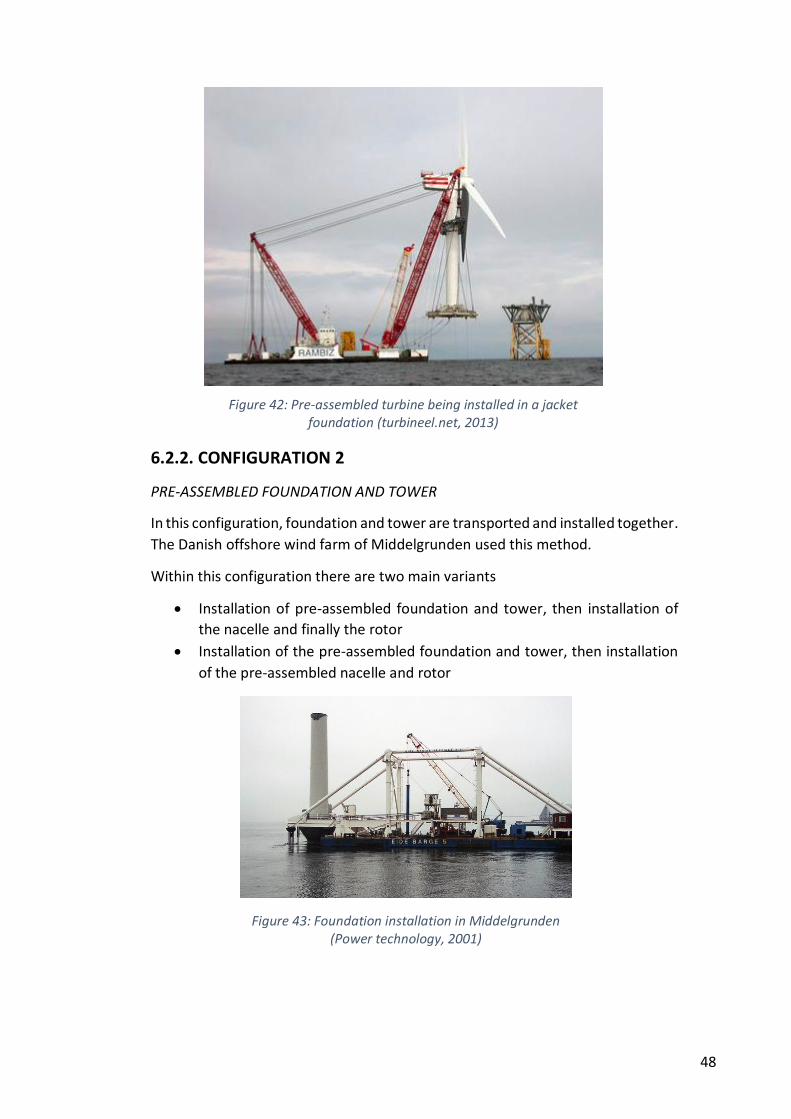
48
6.2.2. CONFIGURATION 2
PRE-ASSEMBLED FOUNDATION AND TOWER
In this configuration, foundation and tower are transported and installed together.
The Danish offshore wind farm of Middelgrunden used this method.
Within this configuration there are two main variants
Installation of pre-assembled foundation and tower, then installation of
the nacelle and finally the rotor
Installation of the pre-assembled foundation and tower, then installation
of the pre-assembled nacelle and rotor
Figure 43: Foundation installation in Middelgrunden (Power technology, 2001)
Figure 42: Pre-assembled turbine being installed in a jacket foundation (turbineel.net, 2013)
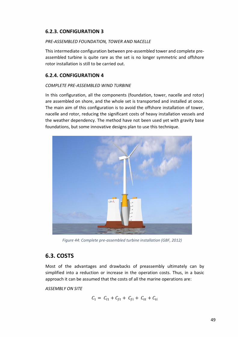
49
6.2.3. CONFIGURATION 3
PRE-ASSEMBLED FOUNDATION, TOWER AND NACELLE
This intermediate configuration between pre-assembled tower and complete pre-
assembled turbine is quite rare as the set is no longer symmetric and offshore
rotor installation is still to be carried out.
6.2.4. CONFIGURATION 4
COMPLETE PRE-ASSEMBLED WIND TURBINE
In this configuration, all the components (foundation, tower, nacelle and rotor)
are assembled on shore, and the whole set is transported and installed at once.
The main aim of this configuration is to avoid the offshore installation of tower,
nacelle and rotor, reducing the significant costs of heavy installation vessels and
the weather dependency. The method have not been used yet with gravity base
foundations, but some innovative designs plan to use this technique.
6.3. COSTS
Most of the advantages and drawbacks of preassembly ultimately can by
simplified into a reduction or increase in the operation costs. Thus, in a basic
approach it can be assumed that the costs of all the marine operations are:
ASSEMBLY ON SITE
𝐶1 = 𝐶𝑙1 + 𝐶𝑓𝑡 + 𝐶𝑓𝑖 + 𝐶𝑡𝑡 + 𝐶𝑡𝑖
Figure 44: Complete pre-assembled turbine installation (GBF, 2012)
50
Where:
C1 : Costs of all the marine operations required to transport and install an
offshore wind turbine, including foundation, tower, nacelle and rotor,
carrying out the assembly on site.
Cl1 : Costs of launching the foundation
Cft : Costs of foundation transport
Cfi : Costs of foundation installation
Ctt : Costs of turbine transport (include tower, nacelle and rotor)
Cti : Costs of turbine installation (include tower, nacelle and rotor)
PRE-ASSEMBLY
𝐶2 = 𝐶𝑝𝑎 + 𝐶𝑙2 + 𝐶𝑡 + 𝐶𝑖
Where:
C2 : Costs of all the marine operations required to transport and install pre-
assembled offshore wind turbine, including foundation, tower, nacelle and
rotor.
Cpa : Costs of preassembly. Includes harbour additional costs.
Cl2 : Costs of ensemble launching
Ct : Costs of transport
Ci : Costs of installation
Costs of transport (Cft, Ctt, Ct)
The costs of transport can be simplified as:
𝐶𝑡∗ = 𝐶𝑚𝑜𝑏𝑡 + ( 𝑡𝑤𝑜𝑟𝑘𝑡 + 𝑡𝑑𝑒𝑙𝑎𝑦𝑡 ) · 𝑞𝑡∗
Ct* : Costs of transport
Cmobt : Costs of mobilization of all the transport equipment required
tworkt : Amount of time that the transport equipment is actually working
tdelayt : Delay time, caused normally both by weather conditions and
technical problems. It will depend on the probability of time windows and
the technical difficulties.
qt* : cost of transport equipment per day of use
Costs of installation (Cfi, Cti, Ci)
The costs of installation can be simplified as:
𝐶𝑖∗ = 𝐶𝑚𝑜𝑏𝑖 + ( 𝑡𝑤𝑜𝑟𝑘𝑖 + 𝑡𝑑𝑒𝑙𝑎𝑦𝑖 ) · 𝑞𝑖∗
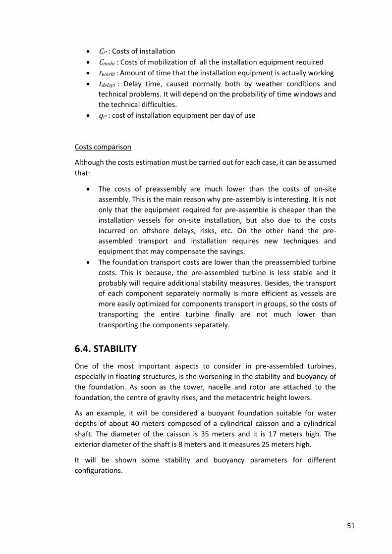
51
Ci* : Costs of installation
Cmobi : Costs of mobilization of all the installation equipment required
tworki : Amount of time that the installation equipment is actually working
tdelayi : Delay time, caused normally both by weather conditions and
technical problems. It will depend on the probability of time windows and
the technical difficulties.
qi* : cost of installation equipment per day of use
Costs comparison
Although the costs estimation must be carried out for each case, it can be assumed
that:
The costs of preassembly are much lower than the costs of on-site
assembly. This is the main reason why pre-assembly is interesting. It is not
only that the equipment required for pre-assemble is cheaper than the
installation vessels for on-site installation, but also due to the costs
incurred on offshore delays, risks, etc. On the other hand the pre-
assembled transport and installation requires new techniques and
equipment that may compensate the savings.
The foundation transport costs are lower than the preassembled turbine
costs. This is because, the pre-assembled turbine is less stable and it
probably will require additional stability measures. Besides, the transport
of each component separately normally is more efficient as vessels are
more easily optimized for components transport in groups, so the costs of
transporting the entire turbine finally are not much lower than
transporting the components separately.
6.4. STABILITY
One of the most important aspects to consider in pre-assembled turbines,
especially in floating structures, is the worsening in the stability and buoyancy of
the foundation. As soon as the tower, nacelle and rotor are attached to the
foundation, the centre of gravity rises, and the metacentric height lowers.
As an example, it will be considered a buoyant foundation suitable for water
depths of about 40 meters composed of a cylindrical caisson and a cylindrical
shaft. The diameter of the caisson is 35 meters and it is 17 meters high. The
exterior diameter of the shaft is 8 meters and it measures 25 meters high.
It will be shown some stability and buoyancy parameters for different
configurations.
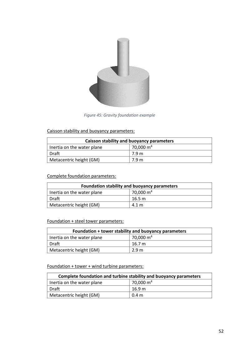
52
Caisson stability and buoyancy parameters:
Caisson stability and buoyancy parameters
Inertia on the water plane 70,000 m4
Draft 7.9 m
Metacentric height (GM) 7.9 m
Complete foundation parameters:
Foundation stability and buoyancy parameters
Inertia on the water plane 70,000 m4
Draft 16.5 m
Metacentric height (GM) 4.1 m
Foundation + steel tower parameters:
Foundation + tower stability and buoyancy parameters
Inertia on the water plane 70,000 m4
Draft 16.7 m
Metacentric height (GM) 2.9 m
Foundation + tower + wind turbine parameters:
Complete foundation and turbine stability and buoyancy parameters
Inertia on the water plane 70,000 m4
Draft 16.9 m
Metacentric height (GM) 0.4 m
Figure 45: Gravity foundation example
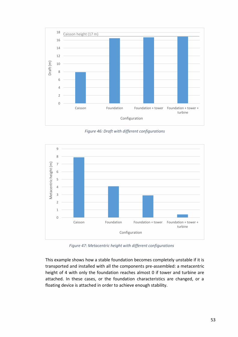
53
This example shows how a stable foundation becomes completely unstable if it is
transported and installed with all the components pre-assembled: a metacentric
height of 4 with only the foundation reaches almost 0 if tower and turbine are
attached. In these cases, or the foundation characteristics are changed, or a
floating device is attached in order to achieve enough stability.
0
1
2
3
4
5
6
7
8
9
Caisson Foundation Foundation + tower Foundation + tower +turbine
Me
tace
ntr
ic h
eigh
t (m
)
Configuration
Figure 47: Metacentric height with different configurations
0
2
4
6
8
10
12
14
16
18
Caisson Foundation Foundation + tower Foundation + tower +turbine
Dra
ft (
m)
Configuration
Caisson height (17 m)
Figure 46: Draft with different configurations
54
6.5. CONFIGURATION CONCLUSIONS
It is clear that the costs estimation have a lot of components to consider and each
foundation have very different features, so there are no generic solution to say if
one configuration is more suitable than other. Each solution must be evaluated,
and even the same foundation design may require different configurations for
different wind farm locations, as the local costs, weather and sea conditions, quay
availability, etc. are different. Some advantages and drawbacks of each
configuration are:
Pre-assembly advantages
Reduction in the weather and sea conditions dependency, which involves
less delays, and less risks associated.
Reduction in heavy installation vessels dependency, and the risks
associated with their low availability.
The time required to install a pre-assembled turbine is lower than the
installation of the foundation and the assembly of tower and turbine on
site.
If the distance to harbour is far, the crew may stay at sea overnight, which
could be expensive and logistically difficult.
The turbines could be tested before being taken out to sea.
Preassembly disadvantages
The standardization of turbine installation methods has allowed a
lowering in the costs, so pre-assembly does not involve a big benefit in
some cases.
Some turbines are not recommended for the movements of being
transported pre-assembled.
The space requirements and specifications of the port are much more
demanding if the components are pre-assembled, so there may not be a
port close to the wind farm suitable for this configuration.
The stability and buoyancy of the foundation decreases with pre-
assembly, so additional floating devices could be necessary.
Wind farm projects are multi-contract projects, so with pre-assembly the
complexity of the contracts rises and the coordination becomes more
difficult.
55
7. CONCLUSIONS AND RECOMMENDATIONS
7.1. CONCLUSIONS
Gravity base foundations are expected to have an important role in offshore wind
projects for the near future. The huge weight and dimensions of these structures,
along with the special offshore conditions, poses a big challenge for engineers.
Marine operations to transport and install the foundations are one of the most
demanding and costly phases of the project, and they have to be planned and
performed carefully.
The operations of transport, seabed preparation, installation and scour protection
were analysed. Within each marine operation, the main procedures and
techniques both used so far, and proposed for the near future were studied. It also
was analysed the main factors to consider in each operation, and the means
required. Besides, a specific chapter (chapter 6) is devoted to different transport
and installation configurations (pre-assembly). Seven operational wind farms, one
under construction, and four future foundations designs has served as a reference
for the study. Procedures and techniques from other offshore construction sectors
has been considered and its possible application commented.
Based on this analysis, the following conclusions are drawn:
So far, transport and installation procedures for GBF have been based on
the use of heavy lift vessels along with pontoons, barges and other heavy
vessels. The intensive use of these enormous means and their low
availability trigger significant costs and risks that companies are trying to
avoid by means of new transport and installation methods, based mainly
on buoyant designs.
The development of offshore wind energy is heading towards larger
foundations and turbines, further distances and deeper waters, which
make not possible the use of current techniques. Thus, future larger
foundations are expected to be transported afloat, allowed by its self-
buoyancy or helped by attached floating devices. These buoyant solutions
would be towed to the wind farms by standard tugs.
Stability of buoyant solutions is a hard issue to handle, especially in pre-
assembled foundations and in caisson base foundations during the
installation phase, where it has been shown how the stability decreases
drastically. Inclined installation methods have solved this latter problem in
foundations for oil platforms.
Seabed preparation has been carried out virtually in the same manner in
all the operational wind farms, based in a dredging and a gravel bed
installation. However, this operation is expensive and the costs will rise
with deeper waters, so offshore wind sector is intending to reduce these
56
costs. Skirted foundations minimize the seabed preparation and offer
other performance advantages.
Scour erosion is likely to occur in GBF, both during the installation and in
the operational phase. Despite there are some prediction models, the
complexity of the phenomenon makes necessary hydraulic model tests.
Some scour protection techniques have been commented, being the
installation of gravel or rocky layers the most commonly used.
The possibility of pre-assemble turbine components to the foundations on
shore is under discussion in the offshore wind sector. There is no generic
solution to this issue, and specific cost and technical analysis must be
performed in each project to assess the most suitable configuration.
Although offshore wind energy is still in its early stages, other sectors have
been working offshore with enormous structures for decades: The
construction of oil and gas platforms, harbours or immersed tunnels have
developed techniques that have been proven many times successfully.
Offshore wind sector still has much to learn from these procedures and
techniques.
7.2. RECOMMENDATIONS
Due to the limited experience of the sector and the lack of accessible information,
it is clear that this work should be updated over time to be adjusted as experience
is gained. Besides, this study can be upgraded by the following recommendations:
Improve the study of the weather and sea conditions required for the
transport and installation of a buoyant GBF and the systems and
techniques to allow the installation in severer conditions.
Deeper analysis of transport and installation configurations (pre-
assembly). Cost model, application to different foundation designs and
wind farm features and comparison of results.
Further stability study of buoyant GBF during transport and installation
phases.
Study of the structural performance of a GBF during the transport and
installation phases.
Environmental impact assessment of the marine operations required for
GBF installation, especially during the seabed preparation.
Further analysis of techniques and procedures used in other offshore
sectors (oil and gas, harbours, immersed tunnels, etc.) and application of
these techniques to offshore wind sector.
57
REFERENCES
ABJV, 2012. ABJV. [Online]
Available at: www.abjv.com
[Accessed 25 May 2013].
Ahmadi, M. & Ghazavi, M., 2012. Effect of Skirt Geometry Variation on Uplift Capacity of
Skirted Foundation, Tehran: ISOPE.
Arup & Hochief, 2011. Gravity base foundations. [Online]
Available at:
http://www.arup.com/Services/~/media/Files/PDF/Publications/Brochure/Arup_Wind_
Energy_Brochure.ashx
[Accessed 28 05 2013].
Carbon Trust, 2012. A boat with suspension and a novel seahorse vessel could help
improve access to Round 3 offshore windfarms. [Online]
Available at: http://www.carbontrust.com/about-us/press/2012/10/a-boat-with-
suspension-and-a-novel-seahorse-vessel-could-help-improve-access-to-round-3-
offshore-windfarms
[Accessed 10 June 2013].
Dahlberg, R., 1983. Observation of scour around offshore structure. Canadian
Geotechnical Journal, 20(4), pp. 617-628.
Danish Energy Agency, 2013. Technical project description for the large scale offshore
wind farm of Horns Rev 3. [Online]
Available at: http://www.ens.dk/sites/ens.dk/files/supply/renewable-energy/wind-
power/offshore-wind-power/new-offshore-wind-
tenders/hr3_technical_project_description_offshore.pdf
[Accessed 24 June 2013].
European Environment Agency, 2010. Tracking progress towards Kyoto and 2020 targets
in Europe, Copenhagen: Publications Office.
EWEA, 2013. Deep water; The next step for offshore wind energy. [Online]
Available at:
http://www.ewea.org/fileadmin/files/library/publications/reports/Deep_Water.pdf
[Accessed 01 August 01].
EWEA, 2013. Wind in power, 2012 European Statistics, s.l.: s.n.
Gifford & BTM, 2009. The transport and installation of concrete foundations. [Online]
Available at:
http://proceedings.ewea.org/offshore2009/allfiles2/284_EOW2009presentation.pdf
[Accessed 10 July 2013].
Gifford, 2009. The transport and installation of concrete gravity foundations. [Online]
Available at:
http://proceedings.ewea.org/offshore2009/allfiles2/284_EOW2009presentation.pdf
[Accessed 10 July 2013].
58
Herman, S., 2002. Offshore wind farms. Analysis of Transport and Installation Costs.
[Online]
Available at: http://www.ecn.nl/docs/library/report/2002/i02002.pdf
[Accessed 10 June 2013].
Hoeg, K., 1991. Foundations for offshore structures. In: Offshore Structures. s.l.:Krieger
Publishing.
International Society for Soil Mechanics and Geotechnical Engineering, 2005.
Geotechnical & Geophysical investigations for offshore and nearshore developments.
[Online]
Available at:
http://www.geonet.nl/upload/documents/dossiers/Investigations%20for%20developme
nts.pdf
[Accessed 22 June 2013].
Jan de Nul S/A, 2012. Kårehamn windfarm foundations. [Online]
Available at: http://www.pianc-
aipcn.be/figuren/verslagen%20activiteiten%20Pianc%20Belgi%C3%AB/vergaderingen%2
0PIANC%20Jongeren/PIANC%20jongeren%20zeebrugge/04%20120426%20JDN%20Wind
farm%20project%20(PIANC%20Zeebrugge)%20light%20[Alleen-
lezen]%20[Compatibiliteitsmodus].
[Accessed 2013 Jun 14].
LORC, 2013. Lindoe Offshore Renewables Center. [Online]
Available at: www.lorc.dk
[Accessed 10 May 2013].
Lunne & John, S., 1979. The use of cone penetrometer tests to compute penetration
resistance of steel skirts underneath North Sea gravity platforms.. In: Design parameters
in geotechnical engineering. London: BGS.
María Alberdi, et al., 2013. Sustainable Energy Supply for a small village. Santander: s.n.
O´Riordan, N. J., Clare, D. G. & Partners, O. A. &., 1990. Geotechnical considerations for
the installation of gravity base structures, Texas: Offshore techonology conference.
O’Connor, M. et al., 2012. Weather windows analysis incorporating wave height, wave.
Dublin, ICOE.
Puolos, H., 1988. Marine geotechnics. Unwin Hyman Ltd., p. 473.
Randolph, M. & Kenkhuis, J., 2001. In: Offshore foundation systems 406: Site investigatio
planning - course notes. s.l.:Center for offshore foundation systems, University of
Wenstern Australia.
Saito, T., Yoshida, Y., Itho, M. & Masui, N., 2008. Skirt suction foundations: aplication to
strait crossing. [Online]
Available at: http://www.pwri.go.jp/eng/ujnr/tc/g/pdf/22/22-6-4saito.pdf
[Accessed 21 June 2013].
59
Seatower, 2012. Cranefree system. [Online]
Available at: http://www.seatower.com/video_how.html
[Accessed 10 July 2013].
Uraz, E., 2011. Offshore Wind Turbine Transportation & Installation Analyses. [Online]
Available at: http://www.hgo.se/wpmaster/2652-
hgo/version/default/part/AttachmentData/data/Final_Presentation_Copy_Emre_Uraz_
17.06.2011_Friday.pdf
[Accessed 05 06 2013].
Vinci Ventus, 2010. Foundation structures for offshore wind. s.l., s.n.
Vølund, P., 2005. Concrete is the future for offshore foundations. Wind Engineering,
29(6), pp. 531-539.
Westgate, Z. J. & DeJong, J. T., 2005. Geotechnical Considerations for Offshore Wind
Turbines. Amherst, MA: U. of Massachusetts and the Massachusetts Technology
Collaborative.
Whitehouse, R., 2004. Marine scour at large foundations. Procedings of the 2nd
Internationa Conference on Scour and Erosion, Singapore, November, pp. 455-463.
Whitehouse, R. S. J. H. J., 2011. Evaluating scour at marine gravity foundations. Maritime
engineering, 164(4), pp. 143-157.
60
APPENDIX A
List of wind farms
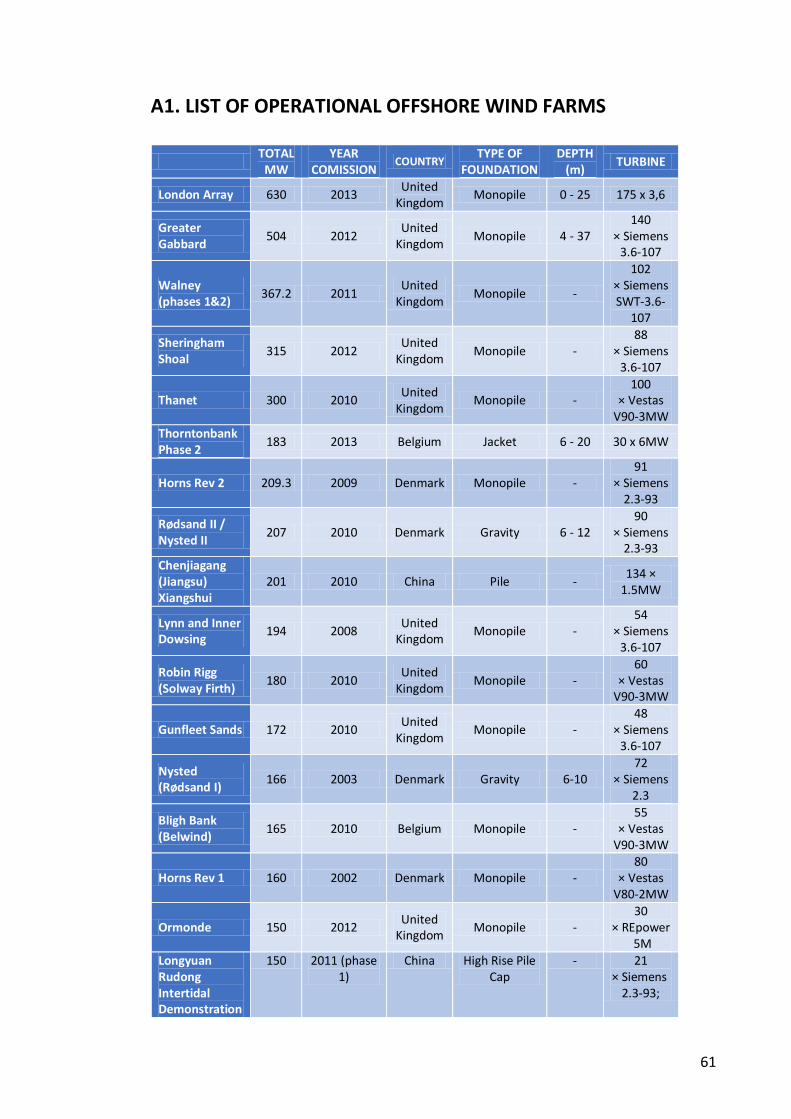
61
A1. LIST OF OPERATIONAL OFFSHORE WIND FARMS
TOTAL
MW YEAR
COMISSION COUNTRY
TYPE OF FOUNDATION
DEPTH (m)
TURBINE
London Array 630 2013 United
Kingdom Monopile 0 - 25 175 x 3,6
Greater Gabbard
504 2012 United
Kingdom Monopile 4 - 37
140 × Siemens
3.6-107
Walney (phases 1&2)
367.2 2011 United
Kingdom Monopile -
102 × Siemens SWT-3.6-
107
Sheringham Shoal
315 2012 United
Kingdom Monopile -
88 × Siemens
3.6-107
Thanet 300 2010 United
Kingdom Monopile -
100 × Vestas
V90-3MW
Thorntonbank Phase 2
183 2013 Belgium Jacket 6 - 20 30 x 6MW
Horns Rev 2 209.3 2009 Denmark Monopile - 91
× Siemens 2.3-93
Rødsand II / Nysted II
207 2010 Denmark Gravity 6 - 12 90
× Siemens 2.3-93
Chenjiagang (Jiangsu) Xiangshui
201 2010 China Pile - 134 ×
1.5MW
Lynn and Inner Dowsing
194 2008 United
Kingdom Monopile -
54 × Siemens
3.6-107
Robin Rigg (Solway Firth)
180 2010 United
Kingdom Monopile -
60 × Vestas
V90-3MW
Gunfleet Sands 172 2010 United
Kingdom Monopile -
48 × Siemens
3.6-107
Nysted (Rødsand I)
166 2003 Denmark Gravity 6-10 72
× Siemens 2.3
Bligh Bank (Belwind)
165 2010 Belgium Monopile - 55
× Vestas V90-3MW
Horns Rev 1 160 2002 Denmark Monopile - 80
× Vestas V80-2MW
Ormonde 150 2012 United
Kingdom Monopile -
30 × REpower
5M
Longyuan Rudong Intertidal Demonstration
150 2011 (phase 1)
China High Rise Pile Cap
- 21 × Siemens
2.3-93;
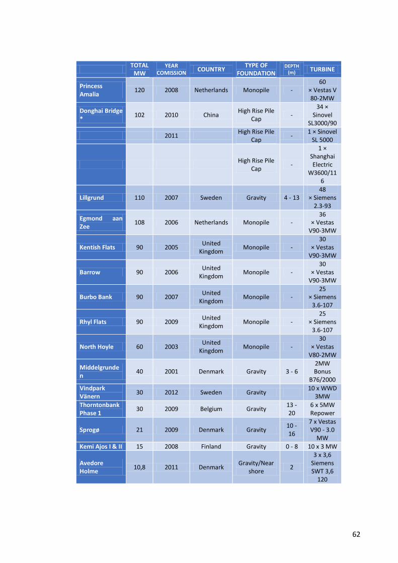
62
TOTAL
MW YEAR
COMISSION COUNTRY
TYPE OF FOUNDATION
DEPTH (m)
TURBINE
Princess Amalia
120 2008 Netherlands Monopile - 60
× Vestas V80-2MW
Donghai Bridge *
102 2010 China High Rise Pile
Cap -
34 × Sinovel
SL3000/90
2011 High Rise Pile
Cap -
1 × Sinovel SL 5000
High Rise Pile
Cap -
1 × Shanghai Electric
W3600/116
Lillgrund 110 2007 Sweden Gravity 4 - 13 48
× Siemens 2.3-93
Egmond aan Zee
108 2006 Netherlands Monopile - 36
× Vestas V90-3MW
Kentish Flats 90 2005 United
Kingdom Monopile -
30 × Vestas
V90-3MW
Barrow 90 2006 United
Kingdom Monopile -
30 × Vestas
V90-3MW
Burbo Bank 90 2007 United
Kingdom Monopile -
25 × Siemens
3.6-107
Rhyl Flats 90 2009 United
Kingdom Monopile -
25 × Siemens
3.6-107
North Hoyle 60 2003 United
Kingdom Monopile -
30 × Vestas
V80-2MW
Middelgrunden
40 2001 Denmark Gravity 3 - 6 2MW Bonus
B76/2000
Vindpark Vänern
30 2012 Sweden Gravity 10 x WWD
3MW
Thorntonbank Phase 1
30 2009 Belgium Gravity 13 - 20
6 x 5MW Repower
Sprogø 21 2009 Denmark Gravity 10 - 16
7 x Vestas V90 - 3.0
MW
Kemi Ajos I & II 15 2008 Finland Gravity 0 - 8 10 x 3 MW
Avedore Holme
10,8 2011 Denmark Gravity/Near
shore 2
3 x 3,6 Siemens SWT 3,6
120
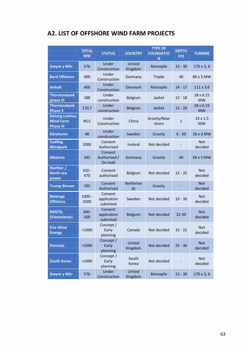
63
A2. LIST OF OFFSHORE WIND FARM PROJECTS
TOTAL
MW STATUS COUNTRY
TYPE OF FOUNDATIO
N
DEPTH (m)
TURBINE
Gwynt y Môr 576 Under
Construction United
Kingdom Monopile 13 - 30 170 x 3, 6
Bard Offshore 400 Under
Construction Germany Tripile 40 80 x 5 MW
Anholt 400 Under
Construction Denmark Monopile 14 - 17 111 x 3.6
Thorntonbank phase III
188 Under
construction Belgium Jacket 12 - 18
18 x 6.15 MW
Thorntonbank Phase 3
110,7 Under
construction Belgium Jacket 12 - 20
18 x 6.15 MW
Datang Laizhou Wind Farm Phase III
49,5 Under
Construction China
Gravity/Near shore
1 33 x 1.5
MW
Kårehamn 48 Under
construction Sweden Gravity 6 - 20 16 x 3 MW
Codling Windpark
1000 Consent
Authorised Ireland Not decided -
Not decided
Albatros 345 Consent
Authorised / On hold
Germany Gravity 40 69 x 5 MW
Norther / North sea power
310 - 470
Consent authorised
Belgium Not decided 12 - 25 Not
decided
Tromp Binnen 295 Consent
Authorised Netherlan
ds Gravity -
Not decided
Blekinge Offshore
1000 - 2500
Consent application submited
Sweden Not decided 10 - 30 Not
decided
RENTEL (Vlaanderen)
300-500
Consent application submited
Belgium Not decided 22-30 Not
decided
Erie Wind Energy
>1000 Concept /
Early planning
Canada Not decided 15 - 22 Not
decided
Hornsea >1000 Concept /
Early planning
United Kingdom
Not decided 25 - 36 Not
decided
South Korea >1000 Concept /
Early planning
South Korea
Not decided - Not
decided
Gwynt y Môr 576 Under
Construction United
Kingdom Monopile 13 - 30 170 x 3, 6
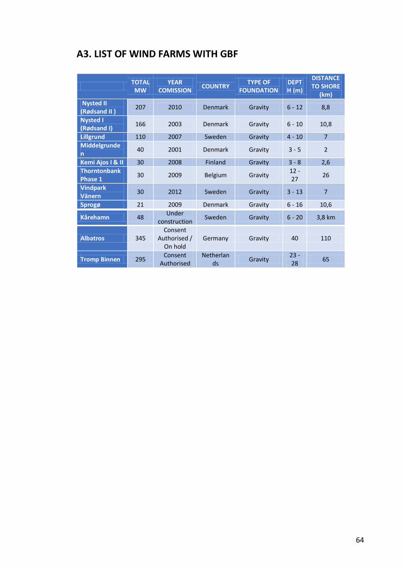
64
A3. LIST OF WIND FARMS WITH GBF
TOTAL
MW YEAR
COMISSION COUNTRY
TYPE OF FOUNDATION
DEPTH (m)
DISTANCE TO SHORE
(km)
Nysted II (Rødsand II )
207 2010 Denmark Gravity 6 - 12 8,8
Nysted I (Rødsand I)
166 2003 Denmark Gravity 6 - 10 10,8
Lillgrund 110 2007 Sweden Gravity 4 - 10 7
Middelgrunden
40 2001 Denmark Gravity 3 - 5 2
Kemi Ajos I & II 30 2008 Finland Gravity 3 - 8 2,6
Thorntonbank Phase 1
30 2009 Belgium Gravity 12 - 27
26
Vindpark Vänern
30 2012 Sweden Gravity 3 - 13 7
Sprogø 21 2009 Denmark Gravity 6 - 16 10,6
Kårehamn 48 Under
construction Sweden Gravity 6 - 20 3,8 km
Albatros 345 Consent
Authorised / On hold
Germany Gravity 40 110
Tromp Binnen 295 Consent
Authorised Netherlan
ds Gravity
23 - 28
65
65
APPENDIX B
Wind farms and future solutions review
66
Appendix B1. Operational and under
construction wind farms
Operational
Nysted II (Rødsand II )
Nysted I (Rødsand I)
Lillgrund
Middelgrunden
Thorntonbank Phase 1
Vindpark Vänern
Sprogø
Under construction
Kårehamn
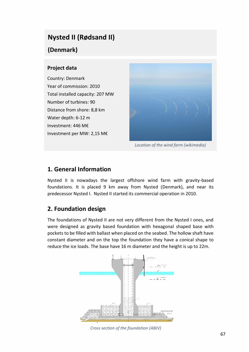
67
1. General Information
Nysted II is nowadays the largest offshore wind farm with gravity-based
foundations. It is placed 9 km away from Nysted (Denmark), and near its
predecessor Nysted I. Nysted II started its commercial operation in 2010.
2. Foundation design
The foundations of Nysted II are not very different from the Nysted I ones, and
were designed as gravity based foundation with hexagonal shaped base with
pockets to be filled with ballast when placed on the seabed. The hollow shaft have
constant diameter and on the top the foundation they have a conical shape to
reduce the ice loads. The base have 16 m diameter and the height is up to 22m.
Project data
Country: Denmark
Year of commission: 2010
Total installed capacity: 207 MW
Number of turbines: 90
Distance from shore: 8,8 km
Water depth: 6-12 m
Investment: 446 M€
Investment per MW: 2,15 M€
Location of the wind farm (wikimedia)
Cross section of the foundation (ABJV)
Nysted II (Rødsand II)
(Denmark)
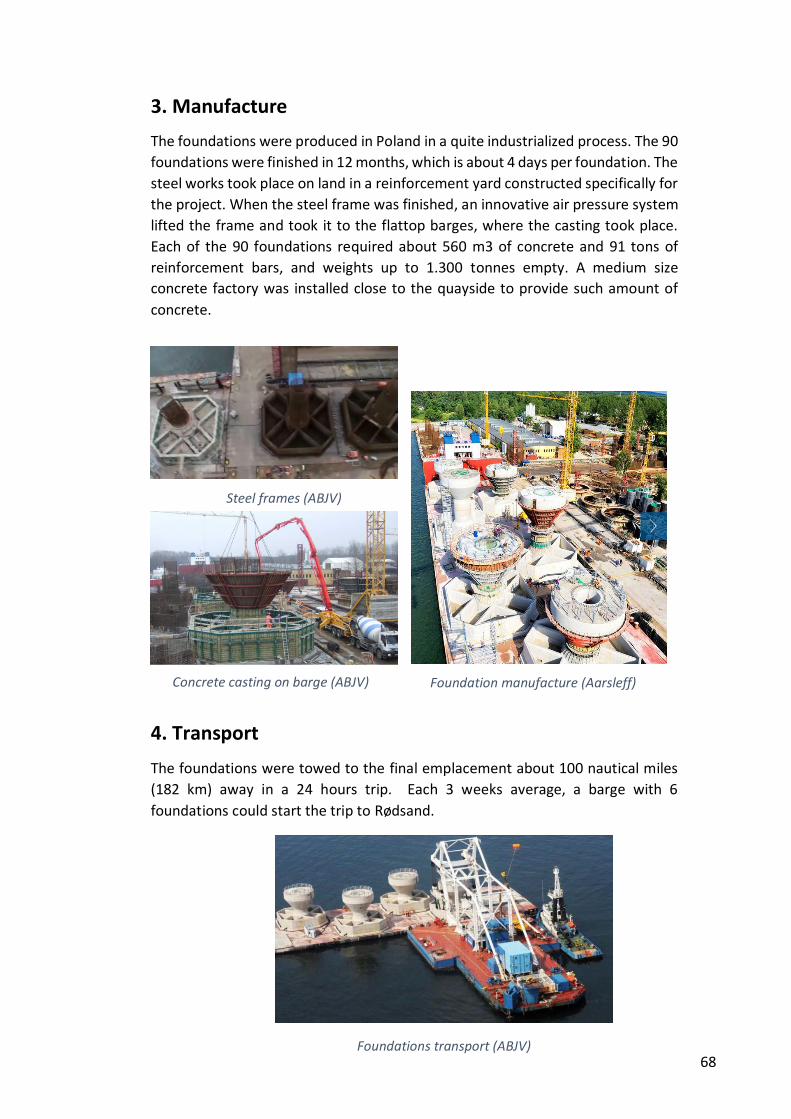
68
3. Manufacture
The foundations were produced in Poland in a quite industrialized process. The 90
foundations were finished in 12 months, which is about 4 days per foundation. The
steel works took place on land in a reinforcement yard constructed specifically for
the project. When the steel frame was finished, an innovative air pressure system
lifted the frame and took it to the flattop barges, where the casting took place.
Each of the 90 foundations required about 560 m3 of concrete and 91 tons of
reinforcement bars, and weights up to 1.300 tonnes empty. A medium size
concrete factory was installed close to the quayside to provide such amount of
concrete.
4. Transport
The foundations were towed to the final emplacement about 100 nautical miles
(182 km) away in a 24 hours trip. Each 3 weeks average, a barge with 6
foundations could start the trip to Rødsand.
Steel frames (ABJV)
Concrete casting on barge (ABJV)
Foundations transport (ABJV)
Foundation manufacture (Aarsleff)
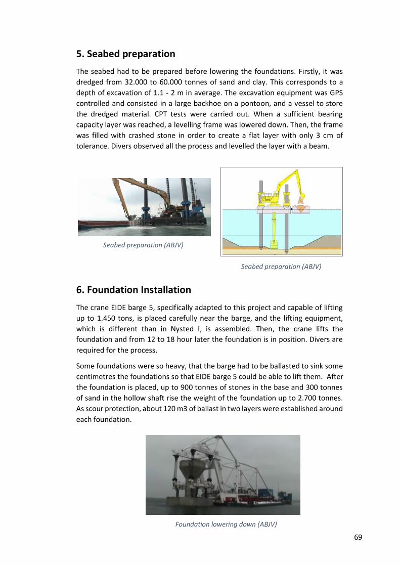
69
5. Seabed preparation
The seabed had to be prepared before lowering the foundations. Firstly, it was
dredged from 32.000 to 60.000 tonnes of sand and clay. This corresponds to a
depth of excavation of 1.1 - 2 m in average. The excavation equipment was GPS
controlled and consisted in a large backhoe on a pontoon, and a vessel to store
the dredged material. CPT tests were carried out. When a sufficient bearing
capacity layer was reached, a levelling frame was lowered down. Then, the frame
was filled with crashed stone in order to create a flat layer with only 3 cm of
tolerance. Divers observed all the process and levelled the layer with a beam.
6. Foundation Installation
The crane EIDE barge 5, specifically adapted to this project and capable of lifting
up to 1.450 tons, is placed carefully near the barge, and the lifting equipment,
which is different than in Nysted I, is assembled. Then, the crane lifts the
foundation and from 12 to 18 hour later the foundation is in position. Divers are
required for the process.
Some foundations were so heavy, that the barge had to be ballasted to sink some
centimetres the foundations so that EIDE barge 5 could be able to lift them. After
the foundation is placed, up to 900 tonnes of stones in the base and 300 tonnes
of sand in the hollow shaft rise the weight of the foundation up to 2.700 tonnes.
As scour protection, about 120 m3 of ballast in two layers were established around
each foundation.
Seabed preparation (ABJV)
Seabed preparation (ABJV)
Foundation lowering down (ABJV)
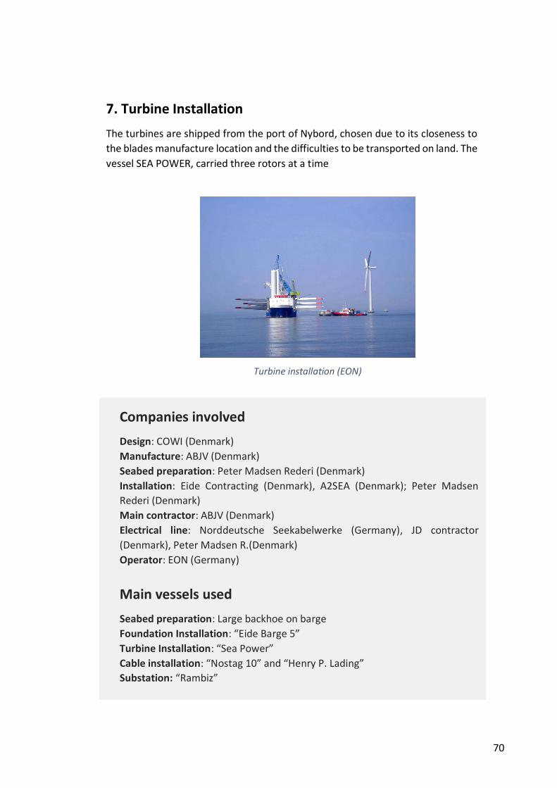
70
7. Turbine Installation
The turbines are shipped from the port of Nybord, chosen due to its closeness to
the blades manufacture location and the difficulties to be transported on land. The
vessel SEA POWER, carried three rotors at a time
Nysted II (Rødsand II)
(Denmark)
Companies involved
Design: COWI (Denmark)
Manufacture: ABJV (Denmark)
Seabed preparation: Peter Madsen Rederi (Denmark)
Installation: Eide Contracting (Denmark), A2SEA (Denmark); Peter Madsen
Rederi (Denmark)
Main contractor: ABJV (Denmark)
Electrical line: Norddeutsche Seekabelwerke (Germany), JD contractor
(Denmark), Peter Madsen R.(Denmark)
Operator: EON (Germany)
Main vessels used
Seabed preparation: Large backhoe on barge
Foundation Installation: “Eide Barge 5”
Turbine Installation: “Sea Power”
Cable installation: “Nostag 10” and “Henry P. Lading”
Substation: “Rambiz”
Turbine installation (EON)
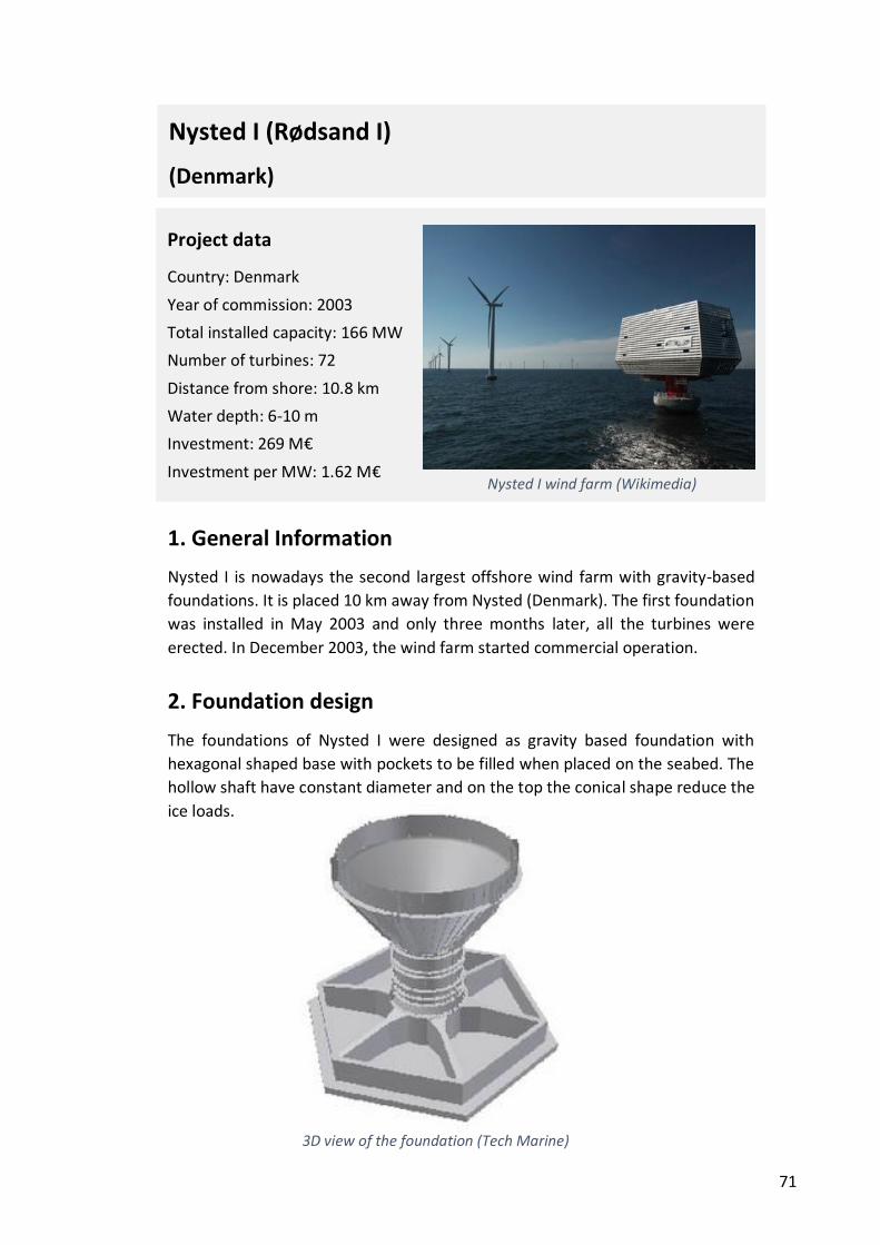
71
1. General Information
Nysted I is nowadays the second largest offshore wind farm with gravity-based
foundations. It is placed 10 km away from Nysted (Denmark). The first foundation
was installed in May 2003 and only three months later, all the turbines were
erected. In December 2003, the wind farm started commercial operation.
2. Foundation design
The foundations of Nysted I were designed as gravity based foundation with
hexagonal shaped base with pockets to be filled when placed on the seabed. The
hollow shaft have constant diameter and on the top the conical shape reduce the
ice loads.
Project data
Country: Denmark
Year of commission: 2003
Total installed capacity: 166 MW
Number of turbines: 72
Distance from shore: 10.8 km
Water depth: 6-10 m
Investment: 269 M€
Investment per MW: 1.62 M€
Nysted I (Rødsand I)
(Denmark)
Nysted I wind farm (Wikimedia)
3D view of the foundation (Tech Marine)
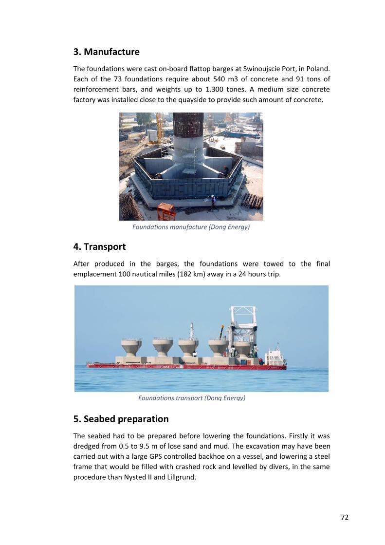
72
3. Manufacture
The foundations were cast on-board flattop barges at Swinoujscie Port, in Poland.
Each of the 73 foundations require about 540 m3 of concrete and 91 tons of
reinforcement bars, and weights up to 1.300 tones. A medium size concrete
factory was installed close to the quayside to provide such amount of concrete.
4. Transport
After produced in the barges, the foundations were towed to the final
emplacement 100 nautical miles (182 km) away in a 24 hours trip.
5. Seabed preparation
The seabed had to be prepared before lowering the foundations. Firstly it was
dredged from 0.5 to 9.5 m of lose sand and mud. The excavation may have been
carried out with a large GPS controlled backhoe on a vessel, and lowering a steel
frame that would be filled with crashed rock and levelled by divers, in the same
procedure than Nysted II and Lillgrund.
Foundations manufacture (Dong Energy)
Foundations transport (Dong Energy)
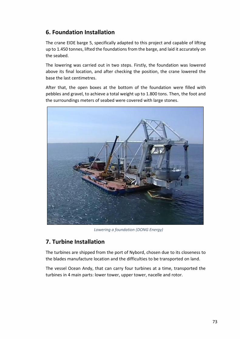
73
6. Foundation Installation
The crane EIDE barge 5, specifically adapted to this project and capable of lifting
up to 1.450 tonnes, lifted the foundations from the barge, and laid it accurately on
the seabed.
The lowering was carried out in two steps. Firstly, the foundation was lowered
above its final location, and after checking the position, the crane lowered the
base the last centimetres.
After that, the open boxes at the bottom of the foundation were filled with
pebbles and gravel, to achieve a total weight up to 1.800 tons. Then, the foot and
the surroundings meters of seabed were covered with large stones.
7. Turbine Installation
The turbines are shipped from the port of Nybord, chosen due to its closeness to
the blades manufacture location and the difficulties to be transported on land.
The vessel Ocean Andy, that can carry four turbines at a time, transported the
turbines in 4 main parts: lower tower, upper tower, nacelle and rotor.
Lowering a foundation (DONG Energy)
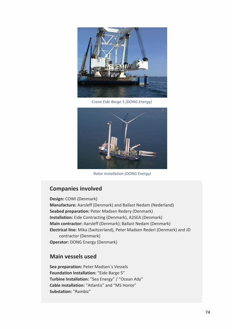
74
Nysted II (Rødsand II)
(Denmark)
Companies involved
Design: COWI (Denmark)
Manufacture: Aarsleff (Denmark) and Ballast Nedam (Nederland)
Seabed preparation: Peter Madsen Redery (Denmark)
Installation: Eide Contracting (Denmark), A2SEA (Denmark)
Main contractor: Aarsleff (Denmark); Ballast Nedam (Denmark)
Electrical line: Mika (Switzerland), Peter Madsen Rederi (Denmark) and JD
contractor (Denmark)
Operator: DONG Energy (Denmark)
Main vessels used
Sea preparation: Peter Madsen´s Vessels
Foundation Installation: “Eide Barge 5”
Turbine Installation: “Sea Energy” / “Ocean Ady”
Cable installation: “Atlantis” and “MS Honte”
Substation: “Rambiz”
Rotor installation (DONG Energy)
Crane Eide Barge 5 (DONG Energy)
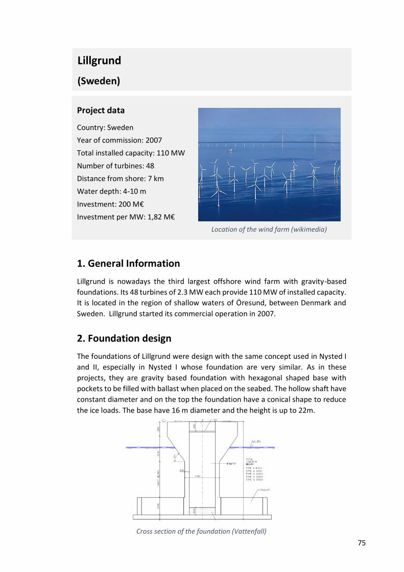
75
1. General Information
Lillgrund is nowadays the third largest offshore wind farm with gravity-based
foundations. Its 48 turbines of 2.3 MW each provide 110 MW of installed capacity.
It is located in the region of shallow waters of Öresund, between Denmark and
Sweden. Lillgrund started its commercial operation in 2007.
2. Foundation design
The foundations of Lillgrund were design with the same concept used in Nysted I
and II, especially in Nysted I whose foundation are very similar. As in these
projects, they are gravity based foundation with hexagonal shaped base with
pockets to be filled with ballast when placed on the seabed. The hollow shaft have
constant diameter and on the top the foundation have a conical shape to reduce
the ice loads. The base have 16 m diameter and the height is up to 22m.
Project data
Country: Sweden
Year of commission: 2007
Total installed capacity: 110 MW
Number of turbines: 48
Distance from shore: 7 km
Water depth: 4-10 m
Investment: 200 M€
Investment per MW: 1,82 M€
Location of the wind farm (wikimedia)
Lillgrund
(Sweden)
Cross section of the foundation (Vattenfall)
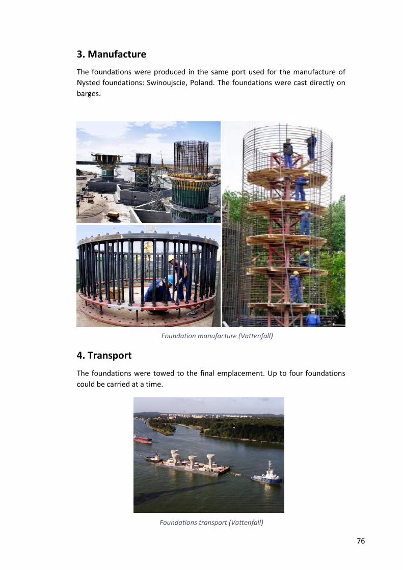
76
3. Manufacture
The foundations were produced in the same port used for the manufacture of
Nysted foundations: Swinoujscie, Poland. The foundations were cast directly on
barges.
4. Transport
The foundations were towed to the final emplacement. Up to four foundations
could be carried at a time.
Foundation manufacture (Vattenfall)
Foundations transport (Vattenfall)
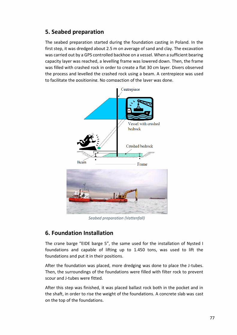
77
5. Seabed preparation
The seabed preparation started during the foundation casting in Poland. In the
first step, it was dredged about 2.5 m on average of sand and clay. The excavation
was carried out by a GPS controlled backhoe on a vessel. When a sufficient bearing
capacity layer was reached, a levelling frame was lowered down. Then, the frame
was filled with crashed rock in order to create a flat 30 cm layer. Divers observed
the process and levelled the crashed rock using a beam. A centrepiece was used
to facilitate the positioning. No compaction of the layer was done.
6. Foundation Installation
The crane barge “EIDE barge 5”, the same used for the installation of Nysted I
foundations and capable of lifting up to 1.450 tons, was used to lift the
foundations and put it in their positions.
After the foundation was placed, more dredging was done to place the J-tubes.
Then, the surroundings of the foundations were filled with filter rock to prevent
scour and J-tubes were fitted.
After this step was finished, it was placed ballast rock both in the pocket and in
the shaft, in order to rise the weight of the foundations. A concrete slab was cast
on the top of the foundations.
Seabed preparation (Vattenfall)
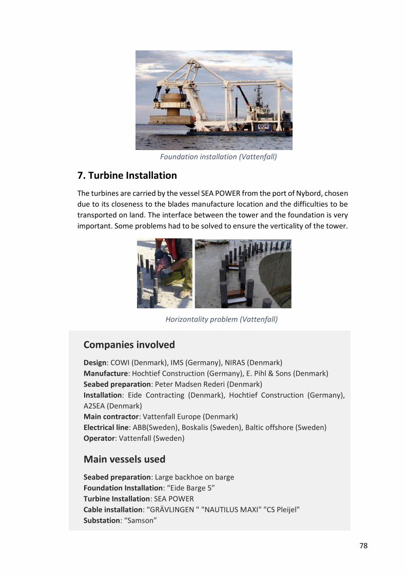
78
7. Turbine Installation
The turbines are carried by the vessel SEA POWER from the port of Nybord, chosen
due to its closeness to the blades manufacture location and the difficulties to be
transported on land. The interface between the tower and the foundation is very
important. Some problems had to be solved to ensure the verticality of the tower.
Nysted II (Rødsand II)
Companies involved
Design: COWI (Denmark), IMS (Germany), NIRAS (Denmark)
Manufacture: Hochtief Construction (Germany), E. Pihl & Sons (Denmark)
Seabed preparation: Peter Madsen Rederi (Denmark)
Installation: Eide Contracting (Denmark), Hochtief Construction (Germany),
A2SEA (Denmark)
Main contractor: Vattenfall Europe (Denmark)
Electrical line: ABB(Sweden), Boskalis (Sweden), Baltic offshore (Sweden)
Operator: Vattenfall (Sweden)
Main vessels used
Seabed preparation: Large backhoe on barge
Foundation Installation: “Eide Barge 5”
Turbine Installation: SEA POWER
Cable installation: “GRÄVLINGEN " "NAUTILUS MAXI" "CS Pleijel"
Substation: “Samson”
Foundation installation (Vattenfall)
Horizontality problem (Vattenfall)
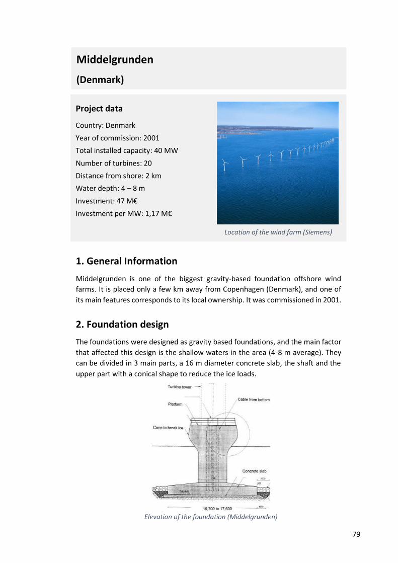
79
1. General Information
Middelgrunden is one of the biggest gravity-based foundation offshore wind
farms. It is placed only a few km away from Copenhagen (Denmark), and one of
its main features corresponds to its local ownership. It was commissioned in 2001.
2. Foundation design
The foundations were designed as gravity based foundations, and the main factor
that affected this design is the shallow waters in the area (4-8 m average). They
can be divided in 3 main parts, a 16 m diameter concrete slab, the shaft and the
upper part with a conical shape to reduce the ice loads.
Project data
Country: Denmark
Year of commission: 2001
Total installed capacity: 40 MW
Number of turbines: 20
Distance from shore: 2 km
Water depth: 4 – 8 m
Investment: 47 M€
Investment per MW: 1,17 M€
Location of the wind farm (Siemens)
Elevation of the foundation (Middelgrunden)
Elevation of the foundation (Middelgrunden)
Middelgrunden
(Denmark)
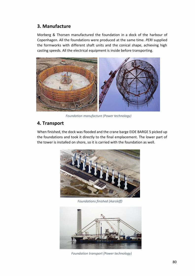
80
3. Manufacture
Morberg & Thorsen manufactured the foundation in a dock of the harbour of
Copenhagen. All the foundations were produced at the same time. PERI supplied
the formworks with different shaft units and the conical shape, achieving high
casting speeds. All the electrical equipment is inside before transporting.
4. Transport
When finished, the dock was flooded and the crane barge EIDE BARGE 5 picked up
the foundations and took it directly to the final emplacement. The lower part of
the tower is installed on shore, so it is carried with the foundation as well.
Foundation manufacture (Power technology)
Foundation transport (Power technology)
Foundations finished (Aarsleff)

81
5. Seabed preparation
The seabed preparation was much more complicated than expected and it had to
be faced some problems. The sludge in the seabed reached up to 5 m, and it was
almost liquid, so it had to be removed several times. Besides, it was placed a layer
of rock as a cushion layer. This layer was supposed to be compacted, but again
some complications were found to achieve the required compaction, so finally it
was necessary to carry out several injections to ensure enough contact. Divers
were necessary in the operations of placement, compaction and levelling of the
compacted rock cushion.
6. Foundation Installation
As explained before, the barge EIDE barge 5 picked up the foundations from the
dock and carried it directly to their final position. This allows savings in other heavy
vessels. The barge was not capable of lifting the weight of the foundation and the
tower, so it had to be transported semi submerged, with a satisfactory method.
Engineers carried out very accurate calculations because the waters in this area
are shallow and the foundation could have stuck in the seabed. The positioning
was very accurate and the special measures planned to solve deviations in
inclinations were not necessary.
Seabed preparation (cranebg)
Foundation installation (ABJV)
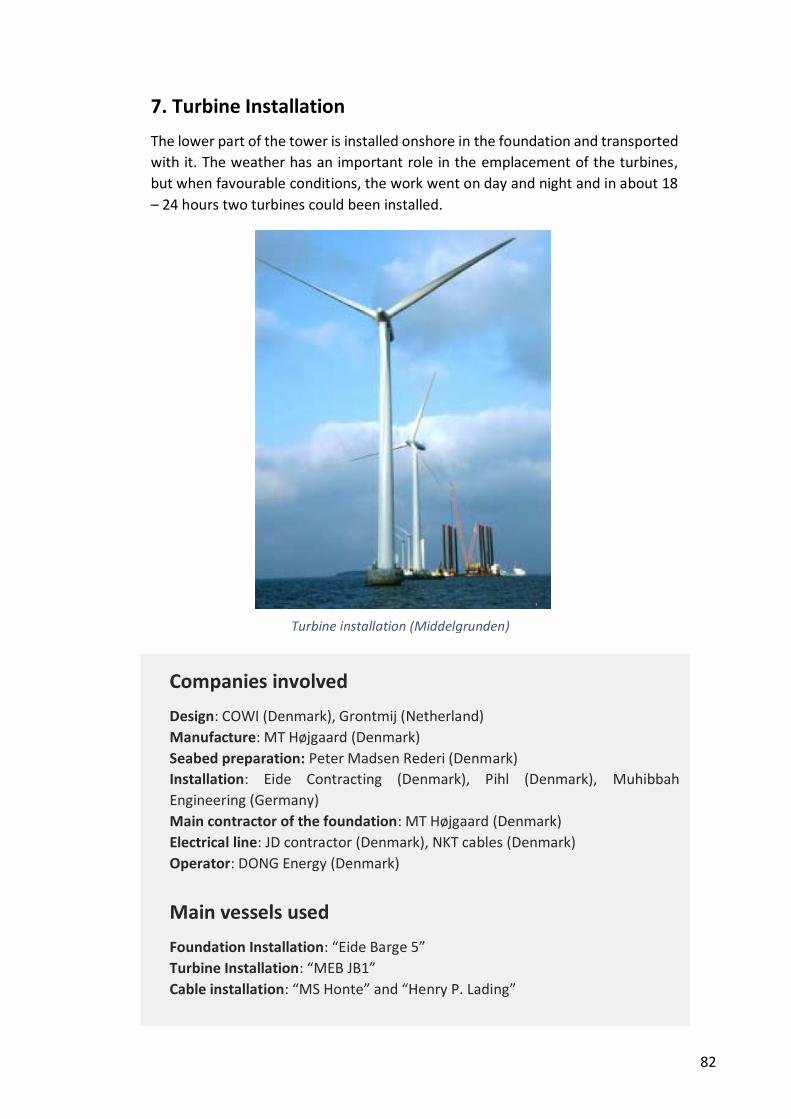
82
7. Turbine Installation
The lower part of the tower is installed onshore in the foundation and transported
with it. The weather has an important role in the emplacement of the turbines,
but when favourable conditions, the work went on day and night and in about 18
– 24 hours two turbines could been installed.
Nysted II (Rødsand II)
(Denmark)
Companies involved
Design: COWI (Denmark), Grontmij (Netherland)
Manufacture: MT Højgaard (Denmark)
Seabed preparation: Peter Madsen Rederi (Denmark)
Installation: Eide Contracting (Denmark), Pihl (Denmark), Muhibbah
Engineering (Germany)
Main contractor of the foundation: MT Højgaard (Denmark)
Electrical line: JD contractor (Denmark), NKT cables (Denmark)
Operator: DONG Energy (Denmark)
Main vessels used
Foundation Installation: “Eide Barge 5”
Turbine Installation: “MEB JB1”
Cable installation: “MS Honte” and “Henry P. Lading”
Turbine installation (Middelgrunden)
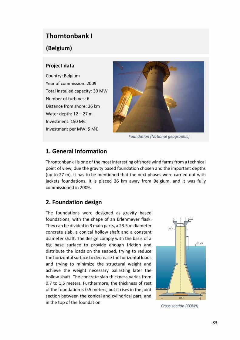
83
1. General Information
Throntonbank I is one of the most interesting offshore wind farms from a technical
point of view, due the gravity based foundation chosen and the important depths
(up to 27 m). It has to be mentioned that the next phases were carried out with
jackets foundations. It is placed 26 km away from Belgium, and it was fully
commissioned in 2009.
2. Foundation design
The foundations were designed as gravity based
foundations, with the shape of an Erlenmeyer flask.
They can be divided in 3 main parts, a 23.5 m diameter
concrete slab, a conical hollow shaft and a constant
diameter shaft. The design comply with the basis of a
big base surface to provide enough friction and
distribute the loads on the seabed, trying to reduce
the horizontal surface to decrease the horizontal loads
and trying to minimize the structural weight and
achieve the weight necessary ballasting later the
hollow shaft. The concrete slab thickness varies from
0.7 to 1,5 meters. Furthermore, the thickness of rest
of the foundation is 0.5 meters, but it rises in the joint
section between the conical and cylindrical part, and
in the top of the foundation.
Project data
Country: Belgium
Year of commission: 2009
Total installed capacity: 30 MW
Number of turbines: 6
Distance from shore: 26 km
Water depth: 12 – 27 m
Investment: 150 M€
Investment per MW: 5 M€
Foundation (National geographic)
Cross section (COWI)
Thorntonbank I
(Belgium)
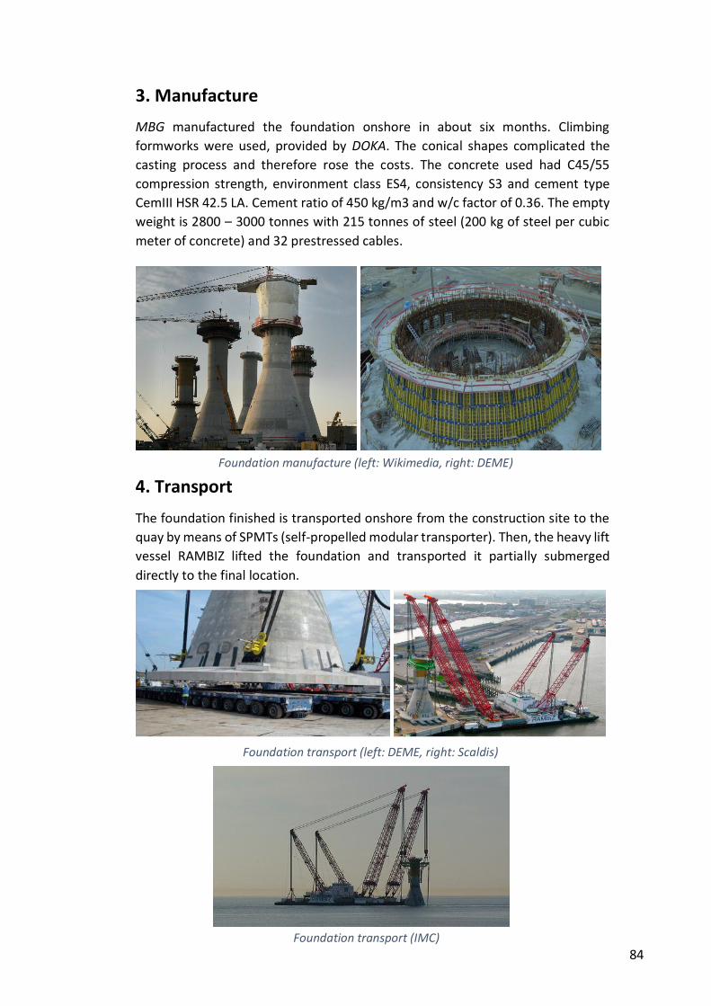
84
3. Manufacture
MBG manufactured the foundation onshore in about six months. Climbing
formworks were used, provided by DOKA. The conical shapes complicated the
casting process and therefore rose the costs. The concrete used had C45/55
compression strength, environment class ES4, consistency S3 and cement type
CemIII HSR 42.5 LA. Cement ratio of 450 kg/m3 and w/c factor of 0.36. The empty
weight is 2800 – 3000 tonnes with 215 tonnes of steel (200 kg of steel per cubic
meter of concrete) and 32 prestressed cables.
4. Transport
The foundation finished is transported onshore from the construction site to the
quay by means of SPMTs (self-propelled modular transporter). Then, the heavy lift
vessel RAMBIZ lifted the foundation and transported it partially submerged
directly to the final location.
Foundation manufacture (left: Wikimedia, right: DEME)
Foundation transport (left: DEME, right: Scaldis)
Foundation transport (IMC)

85
5. Seabed preparation
The seabed was prepared in two steps. Firstly, the first layer of loose sand was
dredged. On average 7 m of sand were dredged in a surface of 50x80 m (90.000
m3 on average per foundation). This sand was disposed nearby in order to reuse
it later as ballast. Then, two layers of crushed rock were laid as foundation bed by
means of a fall pipe vessel. The thicknesses of these layers were about 1,3 m both.
The first layer consisted in a filter layer (0-63mm) and the next was a gravel layer
(10-80mm). An accuracy of 5 cm was required in order to ensure the horizontality.
6. Foundation Installation
As explained before, the heavy lift vessel RAMBIZ picked up the foundations in the
quay and carried it semi submerged directly to their final position. This allows
savings in other heavy vessels but the high dependency in this vessel is risky.
Applying highly accurate positioning systems, the foundation is sunk slowly. Two
days were required from the hoisting in the quay to the final emplacement.
Then the foundation pit was backfilled with up to 60.000 m3 per pit. The hopper
dredger “Jade River” re-dredged the stockpiled sand and pumped it to “Thornton
I”, a multipurpose pontoon that controlled the spreading of the sand. A similar
operation was carried out to fill the foundation hollow with 2000 m3 of sand on
average. The main difference is that the material was dredged and pumped by
“Vlaanderen XXI” in this case.
Finally, “Thornton I” installed the scour protection in two separate layers of rocky
material supplied by “Vlaanderen XXI”: one filter layer (0-120mm) of 0.6m
thickness, and one armour layer (20% of 5-40 kg and 80% of 200kg) of 0.7m
thickness.
Seabed preparation (DEME)
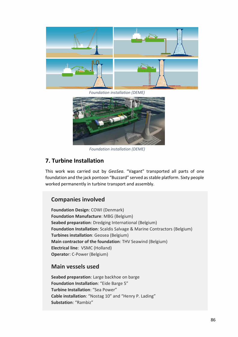
86
7. Turbine Installation
This work was carried out by GeoSea. “Vagant” transported all parts of one
foundation and the jack pontoon “Buzzard” served as stable platform. Sixty people
worked permanently in turbine transport and assembly.
Nysted II (Rødsand II)
(Denmark)
Companies involved
Foundation Design: COWI (Denmark)
Foundation Manufacture: MBG (Belgium)
Seabed preparation: Dredging International (Belgium)
Foundation Installation: Scaldis Salvage & Marine Contractors (Belgium)
Turbines installation: Geosea (Belgium)
Main contractor of the foundation: THV Seawind (Belgium)
Electrical line: VSMC (Holland)
Operator: C-Power (Belgium)
Main vessels used
Seabed preparation: Large backhoe on barge
Foundation Installation: “Eide Barge 5”
Turbine Installation: “Sea Power”
Cable installation: “Nostag 10” and “Henry P. Lading”
Substation: “Rambiz”
Foundation installation (DEME)
Foundation installation (DEME)
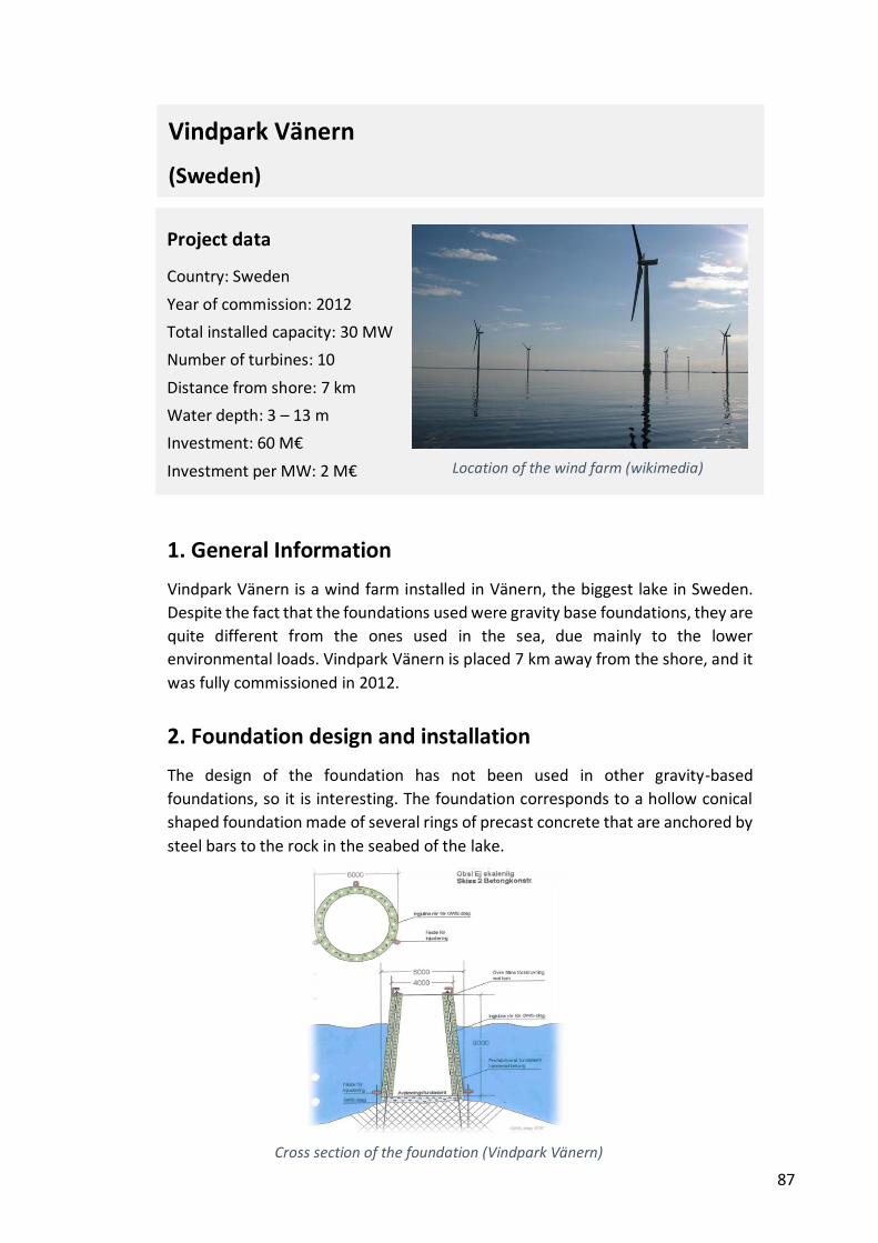
87
1. General Information
Vindpark Vänern is a wind farm installed in Vänern, the biggest lake in Sweden.
Despite the fact that the foundations used were gravity base foundations, they are
quite different from the ones used in the sea, due mainly to the lower
environmental loads. Vindpark Vänern is placed 7 km away from the shore, and it
was fully commissioned in 2012.
2. Foundation design and installation
The design of the foundation has not been used in other gravity-based
foundations, so it is interesting. The foundation corresponds to a hollow conical
shaped foundation made of several rings of precast concrete that are anchored by
steel bars to the rock in the seabed of the lake.
Project data
Country: Sweden
Year of commission: 2012
Total installed capacity: 30 MW
Number of turbines: 10
Distance from shore: 7 km
Water depth: 3 – 13 m
Investment: 60 M€
Investment per MW: 2 M€
Location of the wind farm (wikimedia)
Cross section of the foundation (Vindpark Vänern)
Vindpark Vänern
(Sweden)
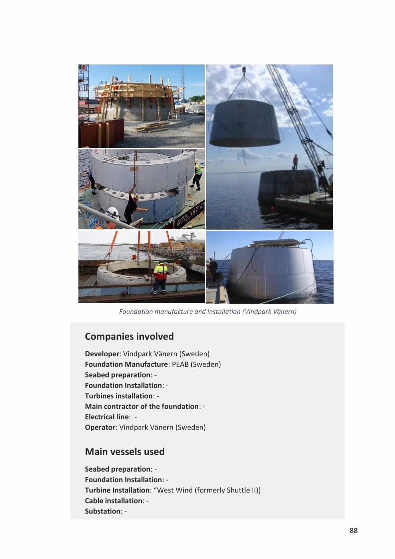
88
Companies involved
Developer: Vindpark Vänern (Sweden)
Foundation Manufacture: PEAB (Sweden)
Seabed preparation: -
Foundation Installation: -
Turbines installation: -
Main contractor of the foundation: -
Electrical line: -
Operator: Vindpark Vänern (Sweden)
Main vessels used
Seabed preparation: -
Foundation Installation: -
Turbine Installation: “West Wind (formerly Shuttle II))
Cable installation: -
Substation: -
Foundation manufacture and installation (Vindpark Vänern)
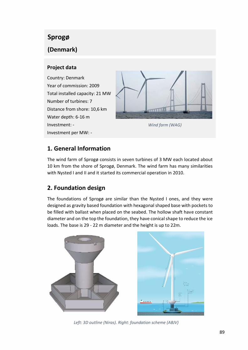
89
1. General Information
The wind farm of Sprogø consists in seven turbines of 3 MW each located about
10 km from the shore of Sprogø, Denmark. The wind farm has many similarities
with Nysted I and II and it started its commercial operation in 2010.
2. Foundation design
The foundations of Sprogø are similar than the Nysted I ones, and they were
designed as gravity based foundation with hexagonal shaped base with pockets to
be filled with ballast when placed on the seabed. The hollow shaft have constant
diameter and on the top the foundation, they have conical shape to reduce the ice
loads. The base is 29 - 22 m diameter and the height is up to 22m.
Project data
Country: Denmark
Year of commission: 2009
Total installed capacity: 21 MW
Number of turbines: 7
Distance from shore: 10,6 km
Water depth: 6-16 m
Investment: -
Investment per MW: -
Wind farm (WAG)
Sprogø
(Denmark)
Left: 3D outline (Niras). Right: foundation scheme (ABJV)

90
3. Manufacture
The foundations were produced at Swinoujscie Port, in Poland, at the same time
than the foundations of Nysted II (Rødsand II). The foundations were cast on-
board one single giant pontoon. Each foundation weights up to 2000 tonnes
empty.
4. Transport
The foundations were manufactured directly on-board a pontoon so when they
were finished, they were towed to the final emplacement about 100 nautical miles
(182 km) away in a 24 hours trip.
Left: Steel frames (Niras). Right: foundation Construction (ABJV)
Wind farm (WAG)
Wind farm (WAG)
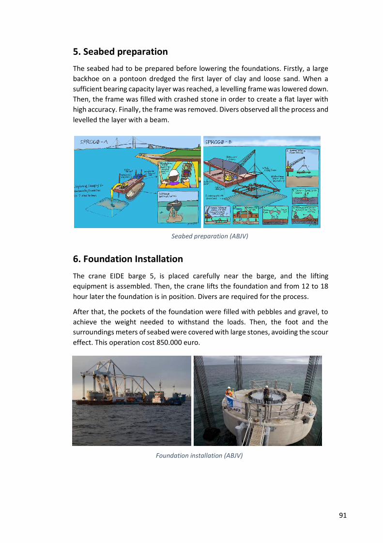
91
5. Seabed preparation
The seabed had to be prepared before lowering the foundations. Firstly, a large
backhoe on a pontoon dredged the first layer of clay and loose sand. When a
sufficient bearing capacity layer was reached, a levelling frame was lowered down.
Then, the frame was filled with crashed stone in order to create a flat layer with
high accuracy. Finally, the frame was removed. Divers observed all the process and
levelled the layer with a beam.
6. Foundation Installation
The crane EIDE barge 5, is placed carefully near the barge, and the lifting
equipment is assembled. Then, the crane lifts the foundation and from 12 to 18
hour later the foundation is in position. Divers are required for the process.
After that, the pockets of the foundation were filled with pebbles and gravel, to
achieve the weight needed to withstand the loads. Then, the foot and the
surroundings meters of seabed were covered with large stones, avoiding the scour
effect. This operation cost 850.000 euro.
Seabed preparation (ABJV)
Foundation installation (ABJV)
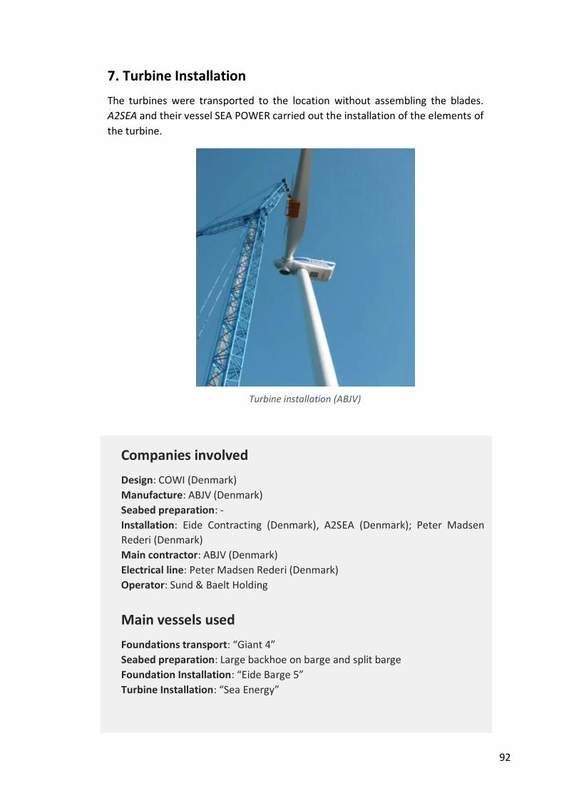
92
7. Turbine Installation
The turbines were transported to the location without assembling the blades.
A2SEA and their vessel SEA POWER carried out the installation of the elements of
the turbine.
Nysted II (Rødsand II)
(Denmark)
Companies involved
Design: COWI (Denmark)
Manufacture: ABJV (Denmark)
Seabed preparation: -
Installation: Eide Contracting (Denmark), A2SEA (Denmark); Peter Madsen
Rederi (Denmark)
Main contractor: ABJV (Denmark)
Electrical line: Peter Madsen Rederi (Denmark)
Operator: Sund & Baelt Holding
Main vessels used
Foundations transport: “Giant 4”
Seabed preparation: Large backhoe on barge and split barge
Foundation Installation: “Eide Barge 5”
Turbine Installation: “Sea Energy”
Turbine installation (EON)
Turbine installation (ABJV)
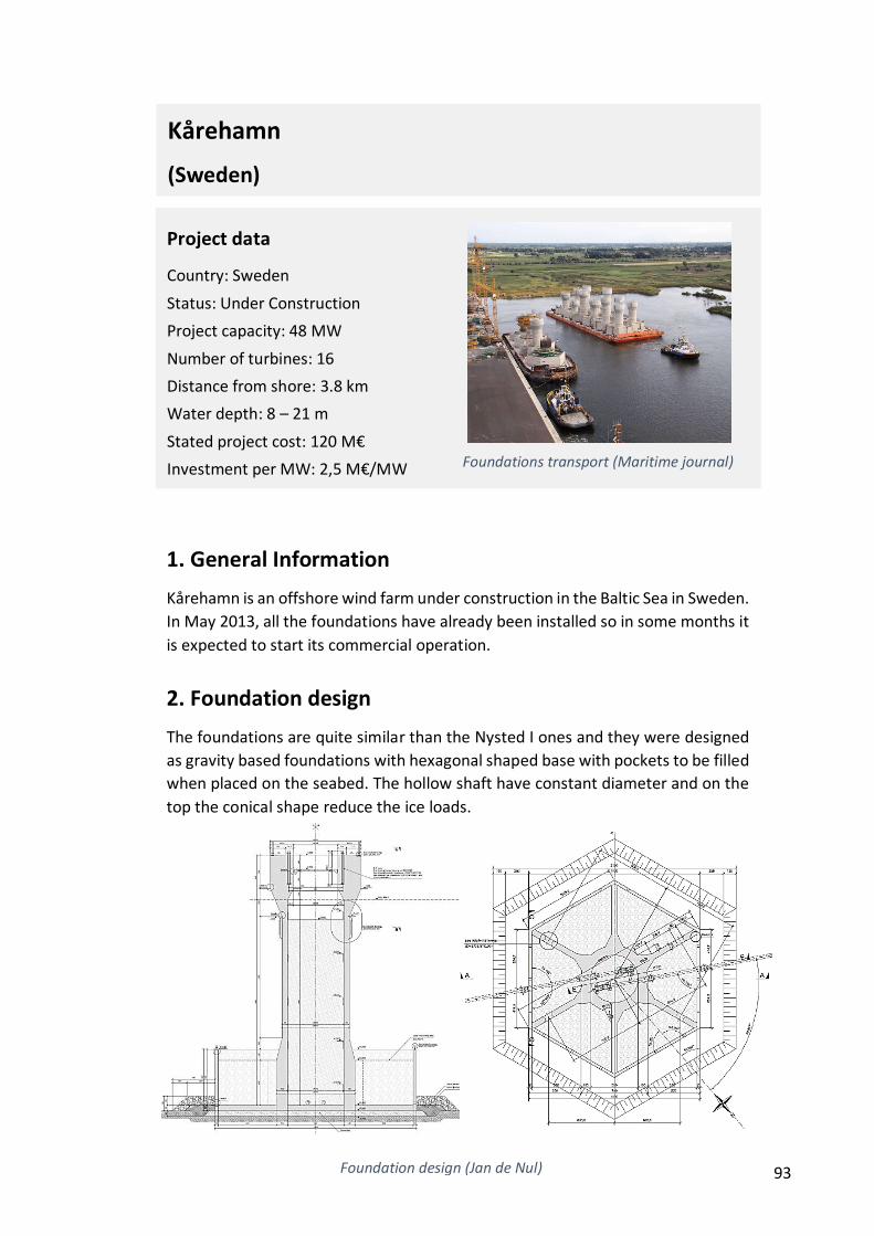
93
1. General Information
Kårehamn is an offshore wind farm under construction in the Baltic Sea in Sweden.
In May 2013, all the foundations have already been installed so in some months it
is expected to start its commercial operation.
2. Foundation design
The foundations are quite similar than the Nysted I ones and they were designed
as gravity based foundations with hexagonal shaped base with pockets to be filled
when placed on the seabed. The hollow shaft have constant diameter and on the
top the conical shape reduce the ice loads.
Project data
Country: Sweden
Status: Under Construction
Project capacity: 48 MW
Number of turbines: 16
Distance from shore: 3.8 km
Water depth: 8 – 21 m
Stated project cost: 120 M€
Investment per MW: 2,5 M€/MW
Foundations transport (Maritime journal)
Foundation design (Jan de Nul)
Kårehamn
(Sweden)

94
3. Manufacture
Jan de Nul manufactured the foundations in the harbour of Zeebrugge (Belgium)
on two pontoons. The cast was carried out in four steps: base plate, walls of the
ballasting pockets, shaft and ice cone. All the foundations have been finished in
about 4 months. 10,000 m3 of concrete C45/55 CemIIIA LA S4 has been poured.
Some section has up to 435 kg/m3 of reinforcement.
4. Transport
The foundations were towed to the final emplacement about 100 nautical miles
(182 km) away in a 24 hours trip. Each 3 weeks average, a barge with 6
foundations could start the trip to Rødsand.
Foundation manufacture (Left: RBS Formworks. Right: Jan de Nul)
Foundation transport (Jan de Nul)
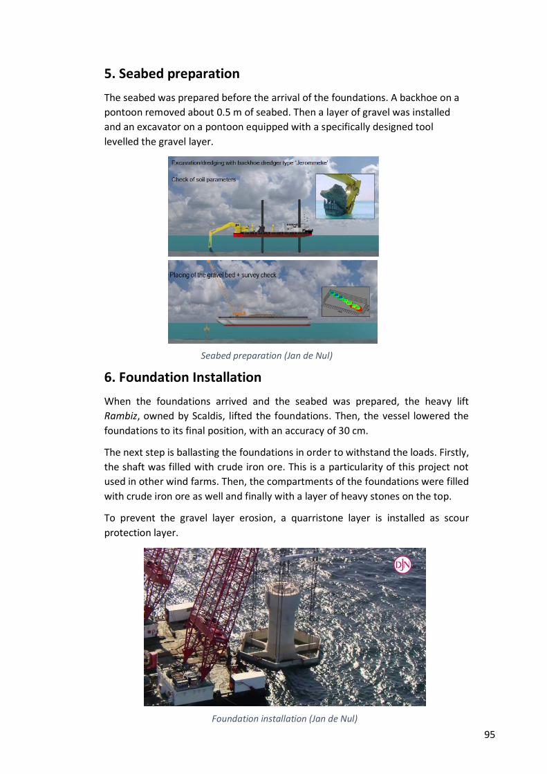
95
5. Seabed preparation
The seabed was prepared before the arrival of the foundations. A backhoe on a
pontoon removed about 0.5 m of seabed. Then a layer of gravel was installed
and an excavator on a pontoon equipped with a specifically designed tool
levelled the gravel layer.
6. Foundation Installation
When the foundations arrived and the seabed was prepared, the heavy lift
Rambiz, owned by Scaldis, lifted the foundations. Then, the vessel lowered the
foundations to its final position, with an accuracy of 30 cm.
The next step is ballasting the foundations in order to withstand the loads. Firstly,
the shaft was filled with crude iron ore. This is a particularity of this project not
used in other wind farms. Then, the compartments of the foundations were filled
with crude iron ore as well and finally with a layer of heavy stones on the top.
To prevent the gravel layer erosion, a quarristone layer is installed as scour
protection layer.
Seabed preparation (Jan de Nul)
Foundation installation (Jan de Nul)
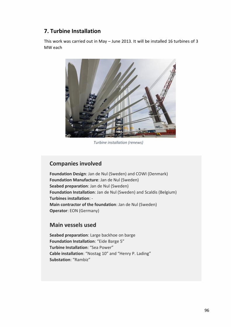
96
7. Turbine Installation
This work was carried out in May – June 2013. It will be installed 16 turbines of 3
MW each
Companies involved
Foundation Design: Jan de Nul (Sweden) and COWI (Denmark)
Foundation Manufacture: Jan de Nul (Sweden)
Seabed preparation: Jan de Nul (Sweden)
Foundation Installation: Jan de Nul (Sweden) and Scaldis (Belgium)
Turbines installation: -
Main contractor of the foundation: Jan de Nul (Sweden)
Operator: EON (Germany)
Main vessels used
Seabed preparation: Large backhoe on barge
Foundation Installation: “Eide Barge 5”
Turbine Installation: “Sea Power”
Cable installation: “Nostag 10” and “Henry P. Lading”
Substation: “Rambiz”
Turbine installation (renews)
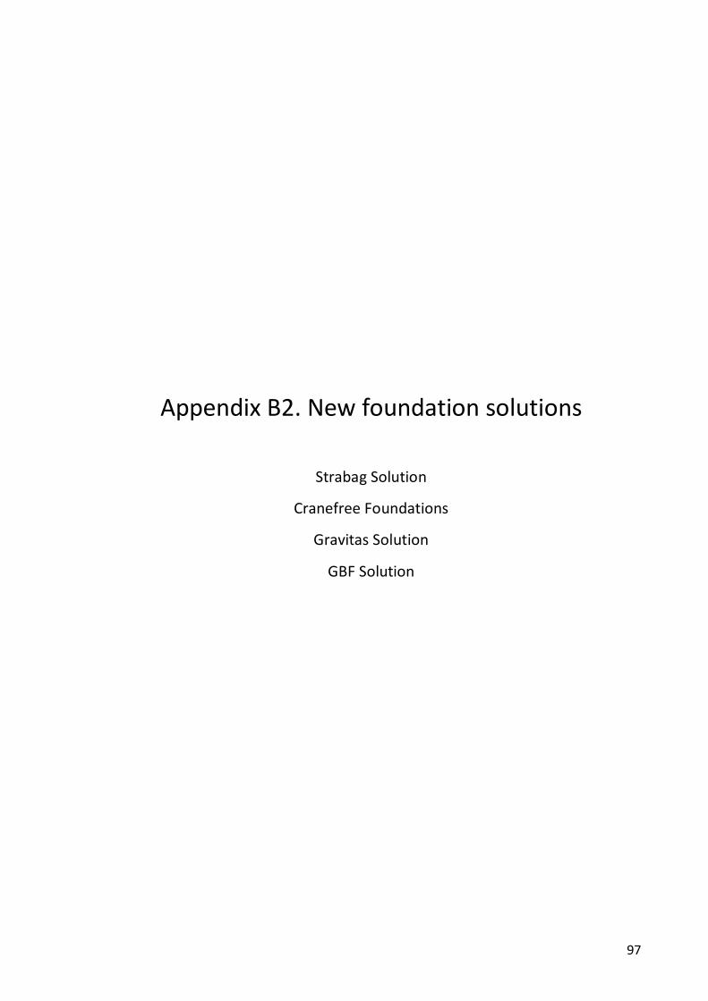
97
Appendix B2. New foundation solutions
Strabag Solution
Cranefree Foundations
Gravitas Solution
GBF Solution
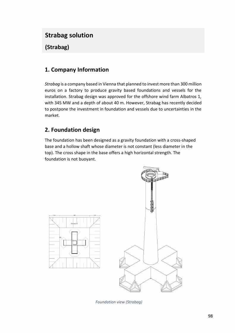
98
1. Company Information
Strabag is a company based in Vienna that planned to invest more than 300 million
euros on a factory to produce gravity based foundations and vessels for the
installation. Strabag design was approved for the offshore wind farm Albatros 1,
with 345 MW and a depth of about 40 m. However, Strabag has recently decided
to postpone the investment in foundation and vessels due to uncertainties in the
market.
2. Foundation design
The foundation has been designed as a gravity foundation with a cross-shaped
base and a hollow shaft whose diameter is not constant (less diameter in the
top). The cross shape in the base offers a high horizontal strength. The
foundation is not buoyant.
Strabag solution
(Strabag)
Foundation view (Strabag)
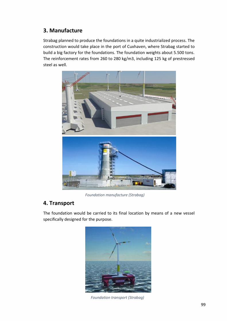
99
3. Manufacture
Strabag planned to produce the foundations in a quite industrialized process. The
construction would take place in the port of Cuxhaven, where Strabag started to
build a big factory for the foundations. The foundation weights about 5.500 tons.
The reinforcement rates from 260 to 280 kg/m3, including 125 kg of prestressed
steel as well.
4. Transport
The foundation would be carried to its final location by means of a new vessel
specifically designed for the purpose.
Foundation manufacture (Strabag)
Foundation transport (Strabag)
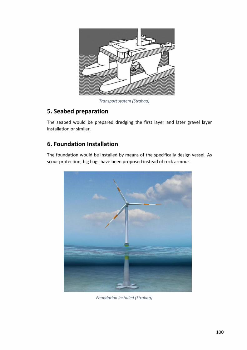
100
5. Seabed preparation
The seabed would be prepared dredging the first layer and later gravel layer
installation or similar.
6. Foundation Installation
The foundation would be installed by means of the specifically design vessel. As
scour protection, big bags have been proposed instead of rock armour.
Transport system (Strabag)
Foundation installed (Strabag)
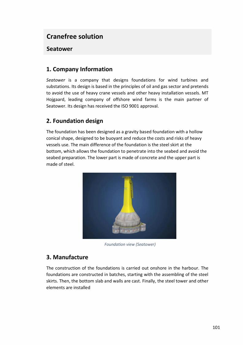
101
1. Company Information
Seatower is a company that designs foundations for wind turbines and
substations. Its design is based in the principles of oil and gas sector and pretends
to avoid the use of heavy crane vessels and other heavy installation vessels. MT
Hojgaard, leading company of offshore wind farms is the main partner of
Seatower. Its design has received the ISO 9001 approval.
2. Foundation design
The foundation has been designed as a gravity based foundation with a hollow
conical shape, designed to be buoyant and reduce the costs and risks of heavy
vessels use. The main difference of the foundation is the steel skirt at the
bottom, which allows the foundation to penetrate into the seabed and avoid the
seabed preparation. The lower part is made of concrete and the upper part is
made of steel.
3. Manufacture
The construction of the foundations is carried out onshore in the harbour. The
foundations are constructed in batches, starting with the assembling of the steel
skirts. Then, the bottom slab and walls are cast. Finally, the steel tower and other
elements are installed
Cranefree solution
Seatower
Foundation view (Seatower)
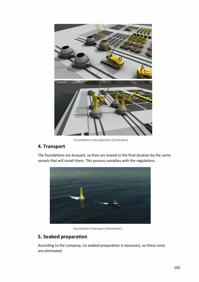
102
4. Transport
The foundations are buoyant, so they are towed to the final location by the same
vessels that will install them. This process complies with the regulations.
5. Seabed preparation
According to the company, no seabed preparation is necessary, so these costs
are eliminated.
Foundation manufacture (Seatower)
Foundation transport (Seatower)
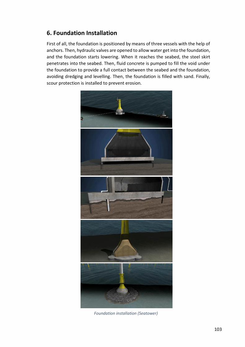
103
6. Foundation Installation
First of all, the foundation is positioned by means of three vessels with the help of
anchors. Then, hydraulic valves are opened to allow water get into the foundation,
and the foundation starts lowering. When it reaches the seabed, the steel skirt
penetrates into the seabed. Then, fluid concrete is pumped to fill the void under
the foundation to provide a full contact between the seabed and the foundation,
avoiding dredging and levelling. Then, the foundation is filled with sand. Finally,
scour protection is installed to prevent erosion.
Foundation installation (Seatower)
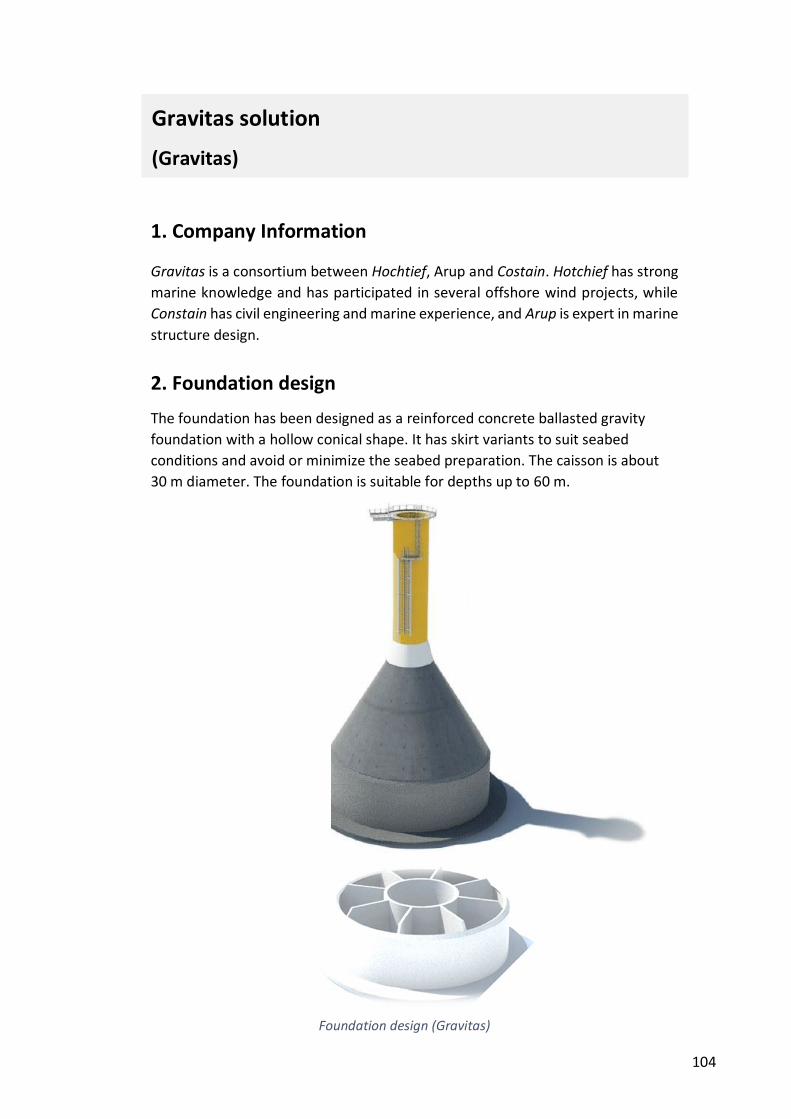
104
1. Company Information
Gravitas is a consortium between Hochtief, Arup and Costain. Hotchief has strong
marine knowledge and has participated in several offshore wind projects, while
Constain has civil engineering and marine experience, and Arup is expert in marine
structure design.
2. Foundation design
The foundation has been designed as a reinforced concrete ballasted gravity
foundation with a hollow conical shape. It has skirt variants to suit seabed
conditions and avoid or minimize the seabed preparation. The caisson is about
30 m diameter. The foundation is suitable for depths up to 60 m.
Gravitas solution
(Gravitas)
Foundation design (Gravitas)
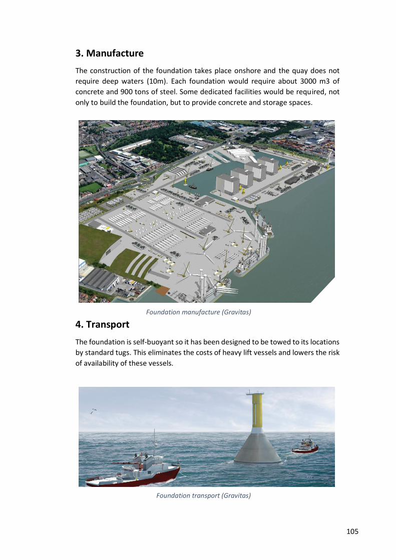
105
3. Manufacture
The construction of the foundation takes place onshore and the quay does not
require deep waters (10m). Each foundation would require about 3000 m3 of
concrete and 900 tons of steel. Some dedicated facilities would be required, not
only to build the foundation, but to provide concrete and storage spaces.
4. Transport
The foundation is self-buoyant so it has been designed to be towed to its locations
by standard tugs. This eliminates the costs of heavy lift vessels and lowers the risk
of availability of these vessels.
Foundation manufacture (Gravitas)
Foundation transport (Gravitas)
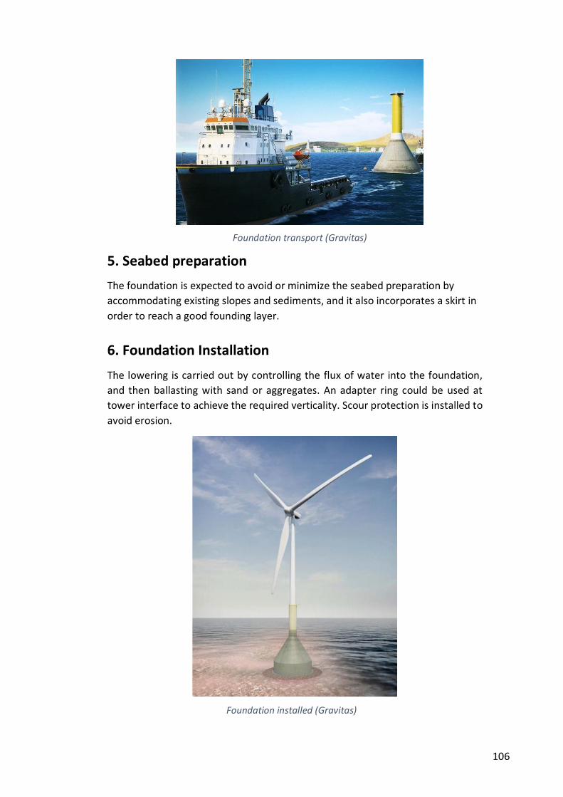
106
5. Seabed preparation
The foundation is expected to avoid or minimize the seabed preparation by
accommodating existing slopes and sediments, and it also incorporates a skirt in
order to reach a good founding layer.
6. Foundation Installation
The lowering is carried out by controlling the flux of water into the foundation,
and then ballasting with sand or aggregates. An adapter ring could be used at
tower interface to achieve the required verticality. Scour protection is installed to
avoid erosion.
Foundation installed (Gravitas)
Foundation transport (Gravitas)
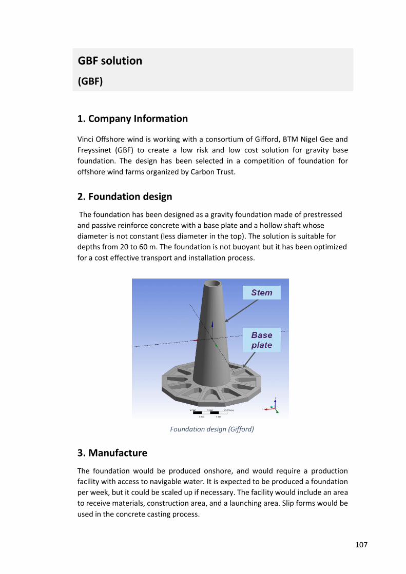
107
1. Company Information
Vinci Offshore wind is working with a consortium of Gifford, BTM Nigel Gee and
Freyssinet (GBF) to create a low risk and low cost solution for gravity base
foundation. The design has been selected in a competition of foundation for
offshore wind farms organized by Carbon Trust.
2. Foundation design
The foundation has been designed as a gravity foundation made of prestressed
and passive reinforce concrete with a base plate and a hollow shaft whose
diameter is not constant (less diameter in the top). The solution is suitable for
depths from 20 to 60 m. The foundation is not buoyant but it has been optimized
for a cost effective transport and installation process.
3. Manufacture
The foundation would be produced onshore, and would require a production
facility with access to navigable water. It is expected to be produced a foundation
per week, but it could be scaled up if necessary. The facility would include an area
to receive materials, construction area, and a launching area. Slip forms would be
used in the concrete casting process.
GBF solution
(GBF)
Foundation design (Gifford)
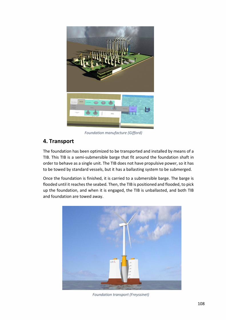
108
4. Transport
The foundation has been optimized to be transported and installed by means of a
TIB. This TIB is a semi-submersible barge that fit around the foundation shaft in
order to behave as a single unit. The TIB does not have propulsive power, so it has
to be towed by standard vessels, but it has a ballasting system to be submerged.
Once the foundation is finished, it is carried to a submersible barge. The barge is
flooded until it reaches the seabed. Then, the TIB is positioned and flooded, to pick
up the foundation, and when it is engaged, the TIB is unballasted, and both TIB
and foundation are towed away.
Foundation manufacture (Gifford)
Foundation transport (Freyssinet)
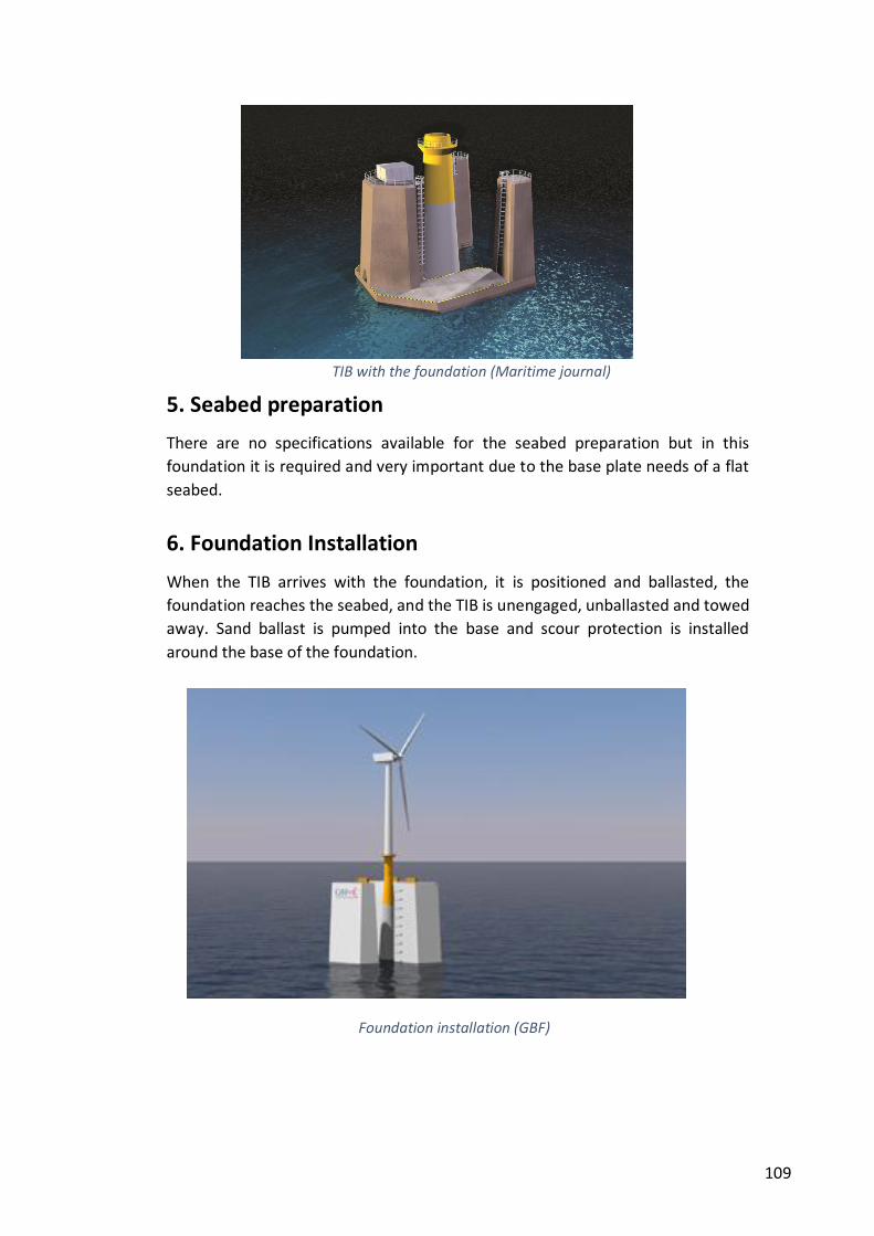
109
5. Seabed preparation
There are no specifications available for the seabed preparation but in this
foundation it is required and very important due to the base plate needs of a flat
seabed.
6. Foundation Installation
When the TIB arrives with the foundation, it is positioned and ballasted, the
foundation reaches the seabed, and the TIB is unengaged, unballasted and towed
away. Sand ballast is pumped into the base and scour protection is installed
around the base of the foundation.
TIB with the foundation (Maritime journal)
Foundation installation (GBF)
110