
Gravitational wave astronomy: the current status - arXiv · PDF fileSpecial Topic: the Next...
41
. Invited Review . Special Topic: the Next Detectors for Gravitational Wave Astronomy SCIENCE CHINA Physics, Mechanics & Astronomy X X Vol. X No. X: XXXXXX doi: 10.1007/s11433-015-5748-6 c Science China Press and Springer-Verlag Berlin Heidelberg 2015 phys.scichina.com link.springer.com Gravitational wave astronomy: the current status † BLAIR David 1 , JU Li 1 , ZHAO ChunNong 1 , WEN LinQing 1 , CHU Qi 1 , FANG Qi 1 , CAI RongGen 2 , GAO JiangRui 3 , LIN XueChun 4 , LIU Dong 5 , WU Ling-An 6 , ZHU ZongHong 7 , REITZE David H. 8,9 , ARAI Koji 8 , ZHANG Fan 7,10 , FLAMINIO Raffaele 11 , ZHU XingJiang 1,12 , HOBBS George 12 , MANCHESTER Richard N. 12 , SHANNON Ryan M. 12,13 , BACCIGALUPI Carlo 14 , GAO Wei 15,16 , XU Peng 15,17 , BIAN Xing 15,16 , CAO ZhouJian 15,18 , CHANG ZiJing 19 , DONG Peng 15,17 , GONG XueFei 15 , HUANG ShuangLin 20 , JU Peng 21 , LUO ZiRen 22,23 , QIANG Li’E 21 , TANG WenLin 24 , WAN XiaoYun 25 , WANG Yue 19 , XU ShengNian 15 , ZANG YunLong 15,16 , ZHANG HaiPeng 20 , LAU Yun-Kau 15,17,19 & NI Wei-Tou 26 1 School of Physics, The University of Western Australia, Crawley WA 6009, Australia; 2 State Key Laboratory of Theoretical Physics, Institute of Theoretical Physics, Chinese Academy of Sciences, Beijing 100190, China; 3 The School of Physics & Electronic Engineering, Shanxi University, Taiyuan 030006, China; 4 Laboratory of All-Solid-State Light Sources, Institute of Semiconductors, Chinese Academy of Science, Beijing 100083, China; 5 State Key Laboratroy of Modern Optical Instrumentation, Department of Optical Engineering, Zhejiang University, Hangzhou 310027, China; 6 Laboratory of Optical Physics, Institute of Physics, Chinese Academy of Sciences, Beijing 100190, China; 7 Gravitational Wave and Cosmology Laboratory, Department of Astronomy, Beijing Normal University, Beijing 100875, China; 8 LIGO Laboratory, California Institute of Technology, MC 100-36, Pasadena, California 91125, USA; 9 Department of Physics, University of Florida, P.O. Box 118440, Gainsville, Florida 32611, USA; 10 Department of Physics, West Virginia University, PO Box 6315, Morgantown, WV 26506, USA; 11 National Astronomical Observatory of Japan, 2-21-1 Osawa, Mitaka, 181-8588 Tokyo, Japan; 12 CSIRO Astronomy and Space Science, PO Box 76, Epping NSW 1710, Australia; 13 International Centre for Radio Astronomy Research, Curtin University, Bentley WA 6102, Australia; 14 SISSA, Astrophysics Sector, via Bonomea 265, 34136, Trieste, Italy; 15 Institute of Applied Mathematics, Academy of Mathematics and Systems Science, Chinese Academy of Sciences, Beijing 100190, China; 16 University of Chinese Academy of Sciences, Beijing 100049, China; 17 Morningside Center of Mathematics, Chinese Academy of Sciences, Beijing 100190, China; 18 State Key Laboratory of Scientific and Engineering Computing, Academy of Mathematics and Systems Science, Chinese Academy of Sciences, Beijing 100190, China; 19 Department of Mathematics, Henan University, Kaifeng 475001, China; 20 Department of Mathematics, Capital Normal University, Beijing 100089, China; 21 Department of Geophysics, College of the Geology Engineering and Geomatics, Chang’an University, Xi’an 710054, China; 22 QUEST Centre of Quantum Engineering and Space-Time Research, Leibniz Universit ¨ at Hannover, 30167, Hannover, Germany; 23 Max-Planck-Institut f¨ ur Gravitationsphysik (Albert Einstein Institut), D-30167 Hannover, Germany; 24 Aerospace Flight Dynamics Laboratory, Beijing Aerospace Control Center, Beijing 100094, China; 25 Qian Xuesen Laboratory of Launch Vehicle Technology, Beijing 100094, China; 26 Center for Gravitation and Cosmology, Department of Physics, Tsing Hua University, Hsinchu 30013, China Received September 24, 2015; accepted September 28, 2015 † Sect. 1 is contributed by BLAIR David, JU Li, ZHAO ChunNong, WEN LinQing, CHU Qi, FANG Qi, CAI RongGen, GAO JiangRui, LIN XueChun, LIU Dong, WU Ling-An, ZHU ZongHong (corresponding author, BLAIR David, email: [email protected]); sect. 2 is contributed by REITZE David H., ARAI Koji, ZHANG Fan (corresponding authors, REITZE David H., email: [email protected]; ZHANG Fan, email: [email protected]); sect. 3 is contributed by FLAMINIO Raffaele (email: raffaele.fl[email protected]); sect. 4 is contributed by ZHU XingJiang, WEN LinQing, HOBBS George, MANCHESTER Richard N., SHANNON Ryan M. (corresponding authors, ZHU XingJiang, email: [email protected]; WEN LinQing, email: lin- [email protected]); sect. 5 is contributed by BACCIGALUPI Carlo (email: [email protected]); sect. 6 is contributed by GAO Wei, XU Peng, BIAN Xing, CAO ZhouJian, CHANG ZiJing, DONG Peng, GONG XueFei, HUANG ShuangLin, JU Peng, LUO ZiRen, QIANG Li’E, TANG WenLin, WAN XiaoYun, WANG Yue, XU ShengNian, ZANG YunLong, ZHANG HaiPeng, LAU Yun-Kau (corresponding author, LAU Yun-Kau, email: [email protected]); sect. 7 is contributed by NI Wei-Tou (email: [email protected]) arXiv:1602.02872v1 [physics.ins-det] 9 Feb 2016
Transcript of Gravitational wave astronomy: the current status - arXiv · PDF fileSpecial Topic: the Next...

. Invited Review .Special Topic: the Next Detectors for Gravitational Wave Astronomy
SCIENCE CHINAPhysics, Mechanics & Astronomy
X X Vol. X No. X: XXXXXXdoi: 10.1007/s11433-015-5748-6
c© Science China Press and Springer-Verlag Berlin Heidelberg 2015 phys.scichina.com link.springer.com
Gravitational wave astronomy: the current status†
BLAIR David1, JU Li1, ZHAO ChunNong1, WEN LinQing1, CHU Qi1, FANG Qi1,CAI RongGen2, GAO JiangRui3, LIN XueChun4, LIU Dong5, WU Ling-An6, ZHU ZongHong7,REITZE David H.8,9, ARAI Koji8, ZHANG Fan7,10, FLAMINIO Raffaele11, ZHU XingJiang1,12,
HOBBS George12, MANCHESTER Richard N.12, SHANNON Ryan M.12,13,BACCIGALUPI Carlo14, GAO Wei15,16, XU Peng15,17, BIAN Xing15,16, CAO ZhouJian15,18,CHANG ZiJing19, DONG Peng15,17, GONG XueFei15, HUANG ShuangLin20, JU Peng21,
LUO ZiRen22,23, QIANG Li’E 21, TANG WenLin24, WAN XiaoYun25, WANG Yue19,XU ShengNian15, ZANG YunLong15,16, ZHANG HaiPeng20, LAU Yun-Kau15,17,19 & NI Wei-Tou26
1School of Physics, The University of Western Australia, Crawley WA 6009, Australia;2State Key Laboratory of Theoretical Physics, Institute of Theoretical Physics, Chinese Academy of Sciences, Beijing 100190, China;
3The School of Physics & Electronic Engineering, Shanxi University, Taiyuan 030006, China;4Laboratory of All-Solid-State Light Sources, Institute of Semiconductors, Chinese Academy of Science, Beijing 100083, China;
5State Key Laboratroy of Modern Optical Instrumentation, Department of Optical Engineering, Zhejiang University, Hangzhou 310027, China;6Laboratory of Optical Physics, Institute of Physics, Chinese Academy of Sciences, Beijing 100190, China;
7Gravitational Wave and Cosmology Laboratory, Department of Astronomy, Beijing Normal University, Beijing 100875, China;8LIGO Laboratory, California Institute of Technology, MC 100-36, Pasadena, California 91125, USA;
9Department of Physics, University of Florida, P.O. Box 118440, Gainsville, Florida 32611, USA;10 Department of Physics, West Virginia University, PO Box 6315, Morgantown, WV 26506, USA;11 National Astronomical Observatory of Japan, 2-21-1 Osawa, Mitaka, 181-8588 Tokyo, Japan;
12 CSIRO Astronomy and Space Science, PO Box 76, Epping NSW 1710, Australia;13 International Centre for Radio Astronomy Research, Curtin University, Bentley WA 6102, Australia;
14 SISSA, Astrophysics Sector, via Bonomea 265, 34136, Trieste, Italy;15 Institute of Applied Mathematics, Academy of Mathematics and Systems Science, Chinese Academy of Sciences, Beijing 100190, China;
16 University of Chinese Academy of Sciences, Beijing 100049, China;17 Morningside Center of Mathematics, Chinese Academy of Sciences, Beijing 100190, China;
18 State Key Laboratory of Scientific and Engineering Computing, Academy of Mathematics and Systems Science,Chinese Academy of Sciences, Beijing 100190, China;
19 Department of Mathematics, Henan University, Kaifeng 475001, China;20 Department of Mathematics, Capital Normal University, Beijing 100089, China;
21 Department of Geophysics, College of the Geology Engineering and Geomatics, Chang’an University, Xi’an 710054, China;22 QUEST Centre of Quantum Engineering and Space-Time Research, Leibniz Universitat Hannover, 30167, Hannover, Germany;
23 Max-Planck-Institut fur Gravitationsphysik (Albert Einstein Institut), D-30167 Hannover, Germany;24 Aerospace Flight Dynamics Laboratory, Beijing Aerospace Control Center, Beijing 100094, China;
25 Qian Xuesen Laboratory of Launch Vehicle Technology, Beijing 100094, China;26 Center for Gravitation and Cosmology, Department of Physics, Tsing Hua University, Hsinchu 30013, China
Received September 24, 2015; accepted September 28, 2015
†Sect. 1 is contributed by BLAIR David, JU Li, ZHAO ChunNong, WEN LinQing, CHU Qi, FANG Qi, CAI RongGen, GAO JiangRui, LIN XueChun,LIU Dong, WU Ling-An, ZHU ZongHong (corresponding author, BLAIR David, email: [email protected]); sect. 2 is contributed by REITZE DavidH., ARAI Koji, ZHANG Fan (corresponding authors, REITZE David H., email: [email protected]; ZHANG Fan, email: [email protected]); sect.3 is contributed by FLAMINIO Raffaele (email: [email protected]); sect. 4 is contributed by ZHU XingJiang, WEN LinQing, HOBBS George,MANCHESTER Richard N., SHANNON Ryan M. (corresponding authors, ZHU XingJiang, email: [email protected]; WEN LinQing, email: [email protected]); sect. 5 is contributed by BACCIGALUPI Carlo (email: [email protected]); sect. 6 is contributed by GAO Wei, XU Peng, BIAN Xing,CAO ZhouJian, CHANG ZiJing, DONG Peng, GONG XueFei, HUANG ShuangLin, JU Peng, LUO ZiRen, QIANG Li’E, TANG WenLin, WAN XiaoYun,WANG Yue, XU ShengNian, ZANG YunLong, ZHANG HaiPeng, LAU Yun-Kau (corresponding author, LAU Yun-Kau, email: [email protected]); sect. 7 iscontributed by NI Wei-Tou (email: [email protected])
arX
iv:1
602.
0287
2v1
[ph
ysic
s.in
s-de
t] 9
Feb
201
6

Blair D, et al. Sci China-Phys Mech Astron X (X) Vol. X No. X XXXXXX-2
In the centenary year of Einstein’s General Theory of Relativity, this paper reviews the current status of gravitational wave as-tronomy across a spectrum which stretches from attohertz to kilohertz frequencies. Sect. 1 of this paper reviews the historicaldevelopment of gravitational wave astronomy from Einstein’s first prediction to our current understanding the spectrum. It isshown that detection of signals in the audio frequency spectrum can be expected very soon, and that a north-south pair of nextgeneration detectors would provide large scientific benefits. Sect. 2 reviews the theory of gravitational waves and the principles ofdetection using laser interferometry. The state of the art Advanced LIGO detectors are then described. These detectors have a highchance of detecting the first events in the near future. Sect. 3 reviews the KAGRA detector currently under development in Japan,which will be the first laser interferometer detector to use cryogenic test masses. Sect. 4 of this paper reviews gravitational wavedetection in the nanohertz frequency band using the technique of pulsar timing. Sect. 5 reviews the status of gravitational wavedetection in the attohertz frequency band, detectable in the polarisation of the cosmic microwave background, and discusses theprospects for detection of primordial waves from the big bang. The techniques described in sects. 1–5 have already placed signifi-cant limits on the strength of gravitational wave sources. Sects. 6 and 7 review ambitious plans for future space based gravitationalwave detectors in the millihertz frequency band. Sect. 6 presents a roadmap for development of space based gravitational wavedetectors by China while sect. 7 discusses a key enabling technology for space interferometry known as time delay interferometry.
gravitational waves, ground based detectors, pulsar timing, spaced based detectors, CMB
PACS number(s): 04.80.Nn, 07.20.Mc, 05.40.-a
Citation: Blair D, Ju L, Zhao C N, et al. Gravitational wave astronomy: the current status. Sci China-Phys Mech Astron, XX, X: XXXXXX, doi: 10.1007/s11433-015-5748-6
Contents
1 Ground based gravitational wave astronomy and opportunities for Australia-China collaboration XXXXXX-31.1 Gravitational wave astronomy . . . . . . . . . . . . . . . . . . . . . . . . . . . . . . . . . . . . . . . . . . . . . . . . . . . . . . . . . . . . XXXXXX-31.2 The event rate for ground based gravitational wave astronomy . . . . . . . . . . . . . . . . . . . . . . . . . . . . . . . XXXXXX-51.3 Advanced LIGO and advanced techniques for future enhancement . . . . . . . . . . . . . . . . . . . . . . . . . . . XXXXXX-61.4 Need for a worldwide array of detectors for gravitational wave astronomy . . . . . . . . . . . . . . . . . . . . XXXXXX-71.5 Conclusion . . . . . . . . . . . . . . . . . . . . . . . . . . . . . . . . . . . . . . . . . . . . . . . . . . . . . . . . . . . . . . . . . . . . . . . . . . . . . XXXXXX-8
2 Introduction to ground based gravitational wave detection and a review of the Advanced LIGO detectorsXXXXXX-9
2.1 Gravitational wave basics . . . . . . . . . . . . . . . . . . . . . . . . . . . . . . . . . . . . . . . . . . . . . . . . . . . . . . . . . . . . . . . . XXXXXX-92.2 A network of ground based detectors . . . . . . . . . . . . . . . . . . . . . . . . . . . . . . . . . . . . . . . . . . . . . . . . . . . . . XXXXXX-92.3 Detecting gravitational waves using interferometry . . . . . . . . . . . . . . . . . . . . . . . . . . . . . . . . . . . . . . . . XXXXXX-10
2.3.1 The basics and detector response to gravitational waves . . . . . . . . . . . . . . . . . . . . . . . . . . . . XXXXXX-102.3.2 Noises . . . . . . . . . . . . . . . . . . . . . . . . . . . . . . . . . . . . . . . . . . . . . . . . . . . . . . . . . . . . . . . . . . . . . . . . XXXXXX-11
2.4 Advanced LIGO . . . . . . . . . . . . . . . . . . . . . . . . . . . . . . . . . . . . . . . . . . . . . . . . . . . . . . . . . . . . . . . . . . . . . . . XXXXXX-13
3 Cryogenic interferometers for enhanced gravitational wave detector sensitivity XXXXXX-133.1 Introduction . . . . . . . . . . . . . . . . . . . . . . . . . . . . . . . . . . . . . . . . . . . . . . . . . . . . . . . . . . . . . . . . . . . . . . . . . . . XXXXXX-133.2 The cryogenic challenges . . . . . . . . . . . . . . . . . . . . . . . . . . . . . . . . . . . . . . . . . . . . . . . . . . . . . . . . . . . . . . . XXXXXX-143.3 The KAGRA solutions . . . . . . . . . . . . . . . . . . . . . . . . . . . . . . . . . . . . . . . . . . . . . . . . . . . . . . . . . . . . . . . . . XXXXXX-153.4 The Einstein Telescope approach . . . . . . . . . . . . . . . . . . . . . . . . . . . . . . . . . . . . . . . . . . . . . . . . . . . . . . . . XXXXXX-173.5 Perspectives in the use of cryogenics for gravitational wave detectors . . . . . . . . . . . . . . . . . . . . . . . XXXXXX-17

Blair D, et al. Sci China-Phys Mech Astron X (X) Vol. X No. X XXXXXX-3
4 Detecting nanohertz gravitational waves with pulsar timing arrays XXXXXX-184.1 Introduction . . . . . . . . . . . . . . . . . . . . . . . . . . . . . . . . . . . . . . . . . . . . . . . . . . . . . . . . . . . . . . . . . . . . . . . . . . . XXXXXX-184.2 Pulsars . . . . . . . . . . . . . . . . . . . . . . . . . . . . . . . . . . . . . . . . . . . . . . . . . . . . . . . . . . . . . . . . . . . . . . . . . . . . . . . XXXXXX-194.3 Pulsar timing techniques . . . . . . . . . . . . . . . . . . . . . . . . . . . . . . . . . . . . . . . . . . . . . . . . . . . . . . . . . . . . . . . XXXXXX-194.4 Noise sources in pulsar timing data . . . . . . . . . . . . . . . . . . . . . . . . . . . . . . . . . . . . . . . . . . . . . . . . . . . . . . XXXXXX-20
4.4.1 Radiometer noise . . . . . . . . . . . . . . . . . . . . . . . . . . . . . . . . . . . . . . . . . . . . . . . . . . . . . . . . . . . . . . . XXXXXX-214.4.2 Pulse jitter noise . . . . . . . . . . . . . . . . . . . . . . . . . . . . . . . . . . . . . . . . . . . . . . . . . . . . . . . . . . . . . . . . XXXXXX-214.4.3 “Timing noise” . . . . . . . . . . . . . . . . . . . . . . . . . . . . . . . . . . . . . . . . . . . . . . . . . . . . . . . . . . . . . . . . . XXXXXX-214.4.4 Dispersion measure variations . . . . . . . . . . . . . . . . . . . . . . . . . . . . . . . . . . . . . . . . . . . . . . . . . . . XXXXXX-214.4.5 Interstellar scintillation . . . . . . . . . . . . . . . . . . . . . . . . . . . . . . . . . . . . . . . . . . . . . . . . . . . . . . . . . . XXXXXX-224.4.6 Correlated noise among different pulsars . . . . . . . . . . . . . . . . . . . . . . . . . . . . . . . . . . . . . . . . . . XXXXXX-22
4.5 Gravitational waves and pulsar timing arrays . . . . . . . . . . . . . . . . . . . . . . . . . . . . . . . . . . . . . . . . . . . . . XXXXXX-224.6 Gravitational wave sources and recent observational results . . . . . . . . . . . . . . . . . . . . . . . . . . . . . . . . XXXXXX-23
4.6.1 Stochastic backgrounds . . . . . . . . . . . . . . . . . . . . . . . . . . . . . . . . . . . . . . . . . . . . . . . . . . . . . . . . . XXXXXX-234.6.2 Continuous waves . . . . . . . . . . . . . . . . . . . . . . . . . . . . . . . . . . . . . . . . . . . . . . . . . . . . . . . . . . . . . . XXXXXX-244.6.3 Gravitational wave memory . . . . . . . . . . . . . . . . . . . . . . . . . . . . . . . . . . . . . . . . . . . . . . . . . . . . . XXXXXX-244.6.4 Gravitational wave bursts . . . . . . . . . . . . . . . . . . . . . . . . . . . . . . . . . . . . . . . . . . . . . . . . . . . . . . . XXXXXX-25
4.7 Summary and future prospects . . . . . . . . . . . . . . . . . . . . . . . . . . . . . . . . . . . . . . . . . . . . . . . . . . . . . . . . . . XXXXXX-25
5 Searching for gravitational waves in the CMB XXXXXX-255.1 Introduction . . . . . . . . . . . . . . . . . . . . . . . . . . . . . . . . . . . . . . . . . . . . . . . . . . . . . . . . . . . . . . . . . . . . . . . . . . . XXXXXX-255.2 CMB anisotropies . . . . . . . . . . . . . . . . . . . . . . . . . . . . . . . . . . . . . . . . . . . . . . . . . . . . . . . . . . . . . . . . . . . . . XXXXXX-265.3 B-mode observations . . . . . . . . . . . . . . . . . . . . . . . . . . . . . . . . . . . . . . . . . . . . . . . . . . . . . . . . . . . . . . . . . . XXXXXX-265.4 Expectations in the near, intermediate and long term . . . . . . . . . . . . . . . . . . . . . . . . . . . . . . . . . . . . . . XXXXXX-27
6 Roadmap for gravitational wave detection in space—a preliminary study XXXXXX-276.1 Introduction . . . . . . . . . . . . . . . . . . . . . . . . . . . . . . . . . . . . . . . . . . . . . . . . . . . . . . . . . . . . . . . . . . . . . . . . . . . XXXXXX-276.2 Gravitational wave detection in space . . . . . . . . . . . . . . . . . . . . . . . . . . . . . . . . . . . . . . . . . . . . . . . . . . . . XXXXXX-276.3 Low-low satellite to satellite tracking using laser interferometry . . . . . . . . . . . . . . . . . . . . . . . . . . . . XXXXXX-286.4 Precision measurement of gravitomagnetic field in terms of gradiometry . . . . . . . . . . . . . . . . . . . . XXXXXX-296.5 Concluding remarks . . . . . . . . . . . . . . . . . . . . . . . . . . . . . . . . . . . . . . . . . . . . . . . . . . . . . . . . . . . . . . . . . . . XXXXXX-31
7 Space missions for gravitational wave detection XXXXXX-317.1 Introduction . . . . . . . . . . . . . . . . . . . . . . . . . . . . . . . . . . . . . . . . . . . . . . . . . . . . . . . . . . . . . . . . . . . . . . . . . . . XXXXXX-317.2 Time delay interferometry . . . . . . . . . . . . . . . . . . . . . . . . . . . . . . . . . . . . . . . . . . . . . . . . . . . . . . . . . . . . . . XXXXXX-317.3 Frequency classification of gravitational waves . . . . . . . . . . . . . . . . . . . . . . . . . . . . . . . . . . . . . . . . . . . XXXXXX-34
1 Ground based gravitational wave astronomyand opportunities for Australia-China collabo-ration
Gravitational wave (GW) detection has become a high pri-ority for physics since advanced technology has enabled thecreation of devices with sufficient sensitivity to detect pre-dicted astronomical signals. This section first presents thehistory of detector developments to highlight the enormousachievements of the field. We summarise the case for build-ing terrestrial detectors, for which it is expected that signalsfrom coalescing pairs of neutron stars will be detectable inthe short term. We emphasise the importance of a worldwidearray of detectors to create an optimum GW telescope. Theimportance of developing the next generation of detectors isemphasised, and the case for a north-south pair of 8 km armlength detectors is presented. Such a system could monitora volume of the universe 60 times larger than the best cur-
rent detectors, enabling precision testing of black hole andneutron star physics.
1.1 Gravitational wave astronomy
The spectrum of electromagnetic waves was predicted inthe paper “A dynamical theory of the electromagnetic field”by Maxwell [1], published in 1865, exactly 150 years ago.Maxwell’s paper predicted waves travelling close to the speedof light, and implied that light was an electromagnetic wave.The harnessing of electromagnetic waves began with the firstexperiments of Hertz [2] between 1886 and 1889. During thenext century as technology developed, the whole spectrum,covering at least 33 decades of frequency, has been harnessed,from the highest energy cosmic ray photons with energies ∼ 1J to Schumann resonances with photon energies ∼ 10−33 J.
The spectrum of GWs is a direct prediction of Einstein’sGeneral Theory of Relativity published in November 1915,

Blair D, et al. Sci China-Phys Mech Astron X (X) Vol. X No. X XXXXXX-4
Table 1 The four main frequency bands for gravitational astronomy
Frequencyband
Cosmological10−16 Hz
Nanohertz band10−9–10−7 Hz
Millihertz band10−4–10−3 Hz
Audio band10–104 Hz
Signal source frozen relic waves from thebig bang at ultralow fre-quency
waves from supermassiveblack holes at a frequency 1cycle per 3 years
waves from massive black holebinaries at 1 cycle per minutepartially masked by galactic bi-nary star systems
audio frequency waves, fromcoalescence of stellar massneutron stars and black holes
Detection tech-nique
B-mode polarisation ofthe cosmic microwavebackground
correlated pulse arrival timevariations of millisecond pulsarsignals
drag free space interferometersof 106 km baselines
high power ground basedmulti-kilometer baselineinterferometers
exactly one hundred years ago. This theory predicts that GWstravel at the speed of light [3]. The prediction of GWs wasnot included in the 1915 paper, but was published in 1916 [4],and then corrected in 1918 [5].
For decades there were arguments about the reality ofGWs. The argument was first clarified by Feynman in 1957when he showed that GWs can do work against frictionalforces [6]. In 1975 Hulse and Taylor [7] discovered the bi-nary pulsar PSR1913+16. Taylor and co-workers monitoredthis system for 20 years, and demonstrated that the systemlost energy exactly as predicted for GW emission, leading tocoalescence in a short time compared with the Hubble time.Hulse and Taylor were awarded the Nobel Prize in 1993 forthis dramatic proof of the existence of GWs. Their discov-ery also demonstrates the existence of a strong, and well de-fined class of GW sources: coalescing compact binary sys-tems. Such sources create a well defined chirp signal in theaudio frequency band when the two stars coalesce. In theHubble volume of the universe such events are predicted tobe occurring at a rate of ∼ 5 per minute. [8]
Weber first discussed the possibility of direct detection ofGWs in the early 1960’s with publication of a paper [9] anda book [10] in which he presented the rationale for GW de-tection. He was the first to show that the GW luminositycould reach c5/G, or ∼ 1023 solar luminosities when twoblack holes coalesce. Thus GW emission could represent themost powerful source of radiation since the big bang.
As technology has developed the possibility of detectionhas increased, and today the detection of GWs has becomea greater and greater priority for physics. Many techniquesfor GW detection are currently under development, as sum-marised in Table 1. The spectrum spans at least 20 decades offrequency, and could extend much higher although sources athigher frequency are speculative. Active programs are under-way across the frequency bands indicated in Table 1, becauseeach frequency band offers different sources. Figure 1 sum-marises the GW spectrum and the instrumental sensitivity tar-gets. Only the most promising sources are summarised in thefigure. The diagonal line is a possible spectrum for stochasticwaves created in the big bang, for which the energy densityis equal in each decade.
The history of space and ground based detectors is shownschematically in Figure 2. In the rest of this paper we willfocus on audio frequency detection, which offers a rich rangeof sources [11] and probably the best near term possibilityof detection. The first GW detectors, developed by Weber,consisted of aluminium bars instrumented with piezo-electriccrystals to detect small vibrations induced by GWs. Bars ofthis type achieved a GW strain sensitivity h ∼ 10−15–10−16
in a narrow bandwidth near 1 kHz. Despite some claims,there was a clear consensus that these detectors had insuffi-cient sensitivity to detect expected astrophysical signals.
Cryogenic resonant mass GW detectors were devel-oped from 1972–2000. They consisted of massive metalbars cooled to cryogenic temperatures with superconductingtransducers [12]. These achieved at least 6 orders of mag-nitude greater flux sensitivity than the original Weber-typedetectors [13, 14]. In the 1990s after 2 decades of develop-ment an array of 5 detectors at Baton Rouge, Frascati, Leg-naro, CERN and Perth, called the International GravitationalEvents Collaboration undertook long term searches. Thesealso failed to identify any signals although there were a fewfalse alarms. The cryogenic bar detectors were mainly sensi-tive to broadband bursts of GW emission from events such as
Figure 1 (Color online) Progress in the development of GW detectors. Thestrain sensitivity figures are indicative only because different data analysismethods can lead, for example, to much higher sensitivity for searches forcontinuous wave sources. Ground based detectors have improved by sevenorder of magnitude over 45 years. Space detectors which first used Dopplertracking of distant spacecraft (Voyager and Cassini) will become very sensi-tive when space interferometers are implemented.

Blair D, et al. Sci China-Phys Mech Astron X (X) Vol. X No. X XXXXXX-5
Figure 2 (Color online) The strain amplitude, main signal sources and de-tector sensitivity for the four main GW detection bands. The sensitivity isonly approximate because integration and correlation techniques allow dif-ferent sensitivities according to data analysis techniques. Cosmic MicrowaveBackground polarisations measurements have recently been shown to be lim-ited by effects of galactic dust. For pulsar timing most sources within theyellow band have been ruled out by observations. The Square Kilometer Ar-ray (SKA) is predicted to allow deeper searches than the recently reportedParkes Pulsar Time Array (PPTA) searches. Advanced LIGO is beginninginitial observations in late 2015.
the collision of black holes or core collapse supernovae, butsensitivity was limited to events occurring within the MilkyWay galaxy. There was a consensus that the event rate forsuch events was too low. Unfortunately sensitivity was insuf-ficient to detect events in more distant galaxies such as theVirgo Cluster, for which the total event rate would be muchlarger.
Over the period that cryogenic bars were being preparedfor operation, the technology for another class of detector—long baseline laser interferometers—was being developed atGlasgow, Munich, MIT, Caltech, Hannover, Paris, Pisa andTokyo. These detectors were ideally suited to detect chirpsignals from the coalescence of binary neutron stars such asthe system discovered by Hulse and Taylor. Since the GW-induced relative displacement increases linearly with armlength, (for light storage times less than half a GW period)long baseline interferometers could in principle be muchmore sensitive than resonant bars, whose length is limitedboth by practical considerations and by the sound velocity inthe bar. By using multiple reflections, interferometers couldachieve an interaction time of up to half a cycle of GWs.
Following successful testing of small scale prototypes,funding was received to build the 300 m TAMA detector inJapan, the 600 m GEO detector near Hannover, Germany, the3 km French-Italian Virgo detector near Pisa in Italy, andtwo 4 km LIGO detectors in the USA, one in Livingston,Louisiana, and the other near Hanford in Washington State.In their initial phase, the long baseline detectors were notexpected to have a high chance of detection, but a secondAdvanced stage was foreshadowed, that would bring the de-tectors to a sensitivity sufficient to detect the coalescence ofbinary neutron stars at a reasonable rate.
1.2 The event rate for ground based gravitational waveastronomy
Neutron star coalescence signals have a well defined wave-form, so that amplitude uncertainty in mainly due to the geo-metrical orientation of the system relative to the detector andthe spectral sensitivity of the interferometer. Matched filter-ing allows optimal signal extraction. This enables standardis-ation of the neutron star inspiral range, assuming a pair of 1.4solar mass neutron stars coalescing in a random orientationrelative to the detector, and a signal to noise ratio (SNR) of 8.This is a useful calibration standard to allow comparison ofdetector sensitivities. However it is important to understandthat the range differs according to the type of source. In par-ticular the coalescence of a pair of 15 solar mass black holescan be detectable to much greater distances.
The initial long baseline laser interferometers achieveda neutron star coalescence range exceeding 16 Mpc, corre-sponding to about 1000 times the diameter of the Milky Way.This was the first time sensitivity had been achieved for aknown class of source far beyond the Milky Way.
Initial LIGO and Virgo accumulated long observationalruns (two years of operation with about 50% multi-detectorduty cycle). At the range achieved, which slightly exceededthe design sensitivity predicted in the 1990s, the neutron starbinary coalescence rate was expected to be about one eventper 20–100 years.
The successful development of sensitive laser interferom-eters required and motivated very important technologicalinnovations, including: a) the development of supermirrorswith extremely low optical losses, b) high purity fused sil-ica with very low optical and acoustic losses, c) high perfor-mance vibration isolation and suspension systems, d) opticalcoatings with reduced acoustic losses, e) the development ofthe concept of optical power recycling which allowed highoptical power interferometers to be created in which the laserpower was built up by resonant amplification. Advanced in-terferometer techniques were also developed, including theconcept of signal recycling and variations in the optical con-figuration in which the signal sidebands can be enhanced. Inturn, all of the above technologies have opened whole newareas of quantum opto-mechanics research.
The Advanced LIGO GW detectors are an implementa-tion of most of the above concepts, as discussed below. andreported in sect. 2 of this paper by Reitze et al. In late 2015Advanced LIGO will begin operation with a greatly increasedrange, of about 70 Mpc. Since the sensitivity is now extendedto regions where the universe is moderately homogeneous,the expected event rate is proportional to the horizon volumeof the universe. Compared to the initial LIGO horizon dis-tance, the expected event rate at the time of writing should beincreased by a factor of (70/16)3, corresponding to a neutronstar coalescence event rate of ∼ 4–0.8 per year. AdvancedVirgo is expected to achieve comparable sensitivity one yearlater.

Blair D, et al. Sci China-Phys Mech Astron X (X) Vol. X No. X XXXXXX-6
The plausibility of the expected Advanced LIGO event ratecan be arrived at very simply, based on the observed popula-tion of compact binary neutron stars, assuming only that weare not preferred observers looking at an exceptional popula-tion of binary pulsars. The event rate is determined statisti-cally, based on the six observed short lived binary pulsar sys-tems. From these 6 local systems in our galaxy, we can esti-mate the total population of potentially observable systems—ones which could be observed in the Milky Way given an ar-bitrarily large radio telescope. This number depends on thelocal distribution of observed pulsars, the size of the MilkyWay and the distribution of systems in the Milky Way. Atypical estimate is ∼ 1000.
Because pulsar signals are beamed, we observe only a frac-tion of all active pulsars. For example, quite soon precessionwill cause the Hulse-Taylor pulsar to become invisible due tomis-orientation. We can estimate the total number of shortlived binary pulsar systems in the Milky Way by correctingfor the pulsar beaming. This increases the total number byan order of magnitude to ∼ 104. To estimate the coalescencerate in the Milky Way, we need an estimate of the mean sys-tem lifetime to coalescence. The above estimates determinethe mean rate of neutron star coalescence events in the MilkyWay. For example, a mean lifetime to coalescence of 108
years leads to a coalescence rate of one per 104 years if thetotal population is 104. Finally, we ask how many Milky Wayequivalent galaxies we require to observe neutron star coa-lescence events at a reasonable rate, say one event per week.This then defines the horizon sensitivity which was chosenfor Advanced LIGO to be about 200 Mpc.
The uncertainty in the above estimate is larger than a nor-mal N−1/2 sampling error because the nearest, lowest radioluminosity binary pulsar system tends to dominate the eventrate. In our case the nearest system is also the shortest life-time system observed to date. It is not possible to knowwhether this nearest binary pulsar is typical or anomalous.The dominance of a single system gives rise to a very largestandard error. The best estimates are given by Abadie etal. in ref. [15] which gives a predicted neutron star coales-cence range between 10−6 and 10−4 per year in the Milkyway galaxy. This range leads to a detectable neutron star co-alescence rate of ∼ 0.4–400 per year at the Advanced LIGOpredicted sensitivity.
The neutron star coalescence event rate can be calibratedagainst other estimators. One is stellar evolution modellingand the second is the abundance of gold. Gold and otherheavy elements have recently been shown to be created fromrapid nucleosynthesis of neutron rich ejecta when neutronstars coalesce. Results from such estimates are broadly con-sistent [16,17] with the observed population estimates. How-ever the uncertainties in all such estimates are also large, es-pecially because the total mass of ejecta can only be predictedby numerical general relativistic hydrodynamical codes, anddepend on an unknown equation of state [18].
The Advanced LIGO event rate estimated in ref. [15] pre-
dicts the most likely event rate to be 40 events per year at fullAdvanced LIGO sensitivity. Others predict that the rate ofblack hole binary coalescence limit is even larger than this.Lee et al. [19] predicted that the black hole binary coales-cence events will be the first signals to be observed by groundbased detectors. Even using the worst case estimates, at fullsensitivity Advanced LIGO should be able to detect one eventper year. Since LIGO has already been shown to be able todetect single very rare events through blind injection testing,there is a consensus that GW detection has now reached apoint at which detection can be expected within 1 or severalyears.
1.3 Advanced LIGO and advanced techniques for fu-ture enhancement
A schematic diagram of an advanced laser interferometer sys-tem such as Advanced LIGO is shown in Figure 3. Theimprovements from initial LIGO to Advanced LIGO is dis-cussed in sect. 2 of this paper. The design is a major upgradeof the initial LIGO detectors, combines improved vibrationisolation to eliminate most of the seismic noise at low fre-quency, larger test masses with monolithic suspensions andhigher acoustic quality factors to reduce thermal noise, andhigher optical power to decrease the shot noise and bring thedetector close to the standard quantum limit at 100 Hz. Thehigh optical power design necessitates the use of transparentreaction masses within the power recycling cavity. In addi-tion, numerous technical improvements are beyond the scopeof this review.
Early commissioning of Advanced LIGO has alreadydemonstrated the validity of the design, as reported in sect.2 of this paper. Current operation is at reduced power levels,but will be increased once techniques for suppression of para-metric instability are implemented. As expected, sensitivityis substantially increased even at 10% of maximum power toa spectral strain sensitivity of a few parts in 1024.
There has been much effort to develop techniques to im-prove sensitivity beyond the standard quantum limit. Thesetechniques include the use of squeezed light techniques andthe use of optomechanics to create non-classical devices.One approach is to modify the quadrature uncertainty of thevacuum fluctuations that enter the interferometer dark port.These fluctuations which normally represent a coherent state(equal uncertainty in both signal quadratures), can be mod-ified by a parametric amplifier, such that the quadrature un-certainty is squeezed in such a way that they contribute min-imum noise to the GW strain signal sidebands. To date, SNRenhancement by 4.3 dB at GEO and 2 dB at LIGO has beendemonstrated at high frequencies. Further improvements canbe attained by using lower optical losses and by using fre-quency dependent squeezing which changes the squeezingangle in phase space as a function of frequency so as to sup-press photon shot noise at high frequency and photon radia-tion pressure noise at low frequency (See Figure 4).

Blair D, et al. Sci China-Phys Mech Astron X (X) Vol. X No. X XXXXXX-7
Figure 3 (Color online) A simplified schematic diagram of an AdvancedLIGO-type interferometer showing the main interferometer, the power recy-cling mirror (PRM), the signal recycling mirror (SRM) and the compensa-tion plates used for correcting thermal aberrations. Mode cleaners are usedto suppress unwanted transverse optical modes. Faraday Isolators (FI) sup-press reflected beams while electro-optic modulators add radio frequencysidebands to the laser light for the locking of laser beams to optical cavities.
f
Figure 4 (Color online) Sensitivity enhancement beyond the free massstandard quantum limit that can be obtained by using frequency dependantsqueezing (second curve), and by combining this with white light signal re-cycling (lower curve). This result assumes an Advanced LIGO type interfer-ometer with reduced mirror coating thermal noise.
Another very promising approach to improvement is byusing white light signal recycling. While squeezing changesthe noise entering the interferometer, signal recycling canchange the dynamics of the interferometer such that the de-tector absorbs more signal from the GW [20]. Normally sig-nal recycling gives rise to narrow band sensitivity improve-ment. White light signal recycling allows resonant powerbuild up across a broad band of signal sideband frequencies.Realisation of this technique calls for non-classical devices,in which the nexus between bandwidth and resonant gain isovercome. Such devices can be created using optomechanicsas described in sect. 6 in ref. [21]
Optomechanics creates non-classical devices by coupling
very narrow linewidth mechanical resonators to laser light viaradiation pressure forces. In principle, appropriately engi-neered devices could be used in the output optics to accessapproximately one order of magnitude sensitivity enhance-ment. Figure 4 shows the areas of improvement that can beobtained by modifying the output optics in the form of fre-quency dependent squeezing and white light signal recycling.
Work is underway to develop devices to enable the abovesensitivity enhancements to be accessed, as discussed inan accompanying paper in this issue (see sect. 6 in ref.[21]). Optomechanics provides a path for existing detectorsto achieve future improvements. Realisation of frequencydependent squeezing can be expected in the short term, butwhite light cavity techniques will require the development ofpractical thermal noise free optomechanics, a process whichis likely to take some years of development.
1.4 Need for a worldwide array of detectors for gravita-tional wave astronomy
GW detection relies on widely separated detectors to min-imise seismic or electromagnetic correlations between detec-tors. By separating detectors widely on the Earth’s surface itis also possible to use time of flight triangulation to determinethe location of sources on the sky. This can be achieved byincoherent comparison of signal arrival times, or optimally,by the coherent combination of all signals.
Chu et al. [22] have analysed various networks of detec-tors. Assuming detectors to have equal sensitivity, one candetermine the distribution of angular resolution achievablefor different arrays. Monte-Carlo simulations were used toidentify 200 random sky locations for binary neutron star(BNS) coalescence events. Standard masses of 1.4 solarmasses for the individual neutron stars of the BNS systemare used. A second order post-Newtonian approximation wasused to define the BNS waveforms. The distances of thoseevents were adjusted so that the combined SNR for the threedetector LHV network is always at 10. Therefore the effectsof adding one or more detectors to the network can be fairlycompared. The Wen-Chen [23] formulae were used to cal-culate the localisation accuracies for different detector net-works.
Figure 5 shows a comparison between the existing threedetector arrays (LIGO and Virgo) and planned detectors inJapan (KAGRA) and LIGO-India. Finally, two new detectorsare considered: a) a detector in China and b) a pair of detec-tors in China and Australia. The detectors and their locationsare listed in Table 2.
We can see from Figure 5 that adding a new detector inAustralia (AIGO) alone has similar angular resolution per-formance to the combined effect of adding both KAGRA andLIGO-India. Chu et al. [22] studied the localisation accura-cies for burst events with different detector networks and

Blair D, et al. Sci China-Phys Mech Astron X (X) Vol. X No. X XXXXXX-8
101 102 1030
0.1
0.2
0.3
0.4
0.5
0.6
0.7
0.8
0.9
1.0
∆Ω 0.90 (sq−degs)
Cum
ulat
iveL
dist
ribut
ion
LHVLHVJLHVILHVALHVJILHVJICLHVJIALHVJIAC
Figure 5 (Color online) Cumulative distribution of error ellipses at 90%confidence level of the 8 detector networks. L−Livingston (US, LIGO);H−Hanford (US, LIGO); V−Virgo (Italy); J−KAGRA (Japan); I−LIGO-India; A−AIGO (Australia); C−China. Assuming that GW sources are ran-domly located with respect to the detector array, the figure shows the fractionof sources with given angular resolution for different array configurarions.Angular resolution varies across the sky by an order of magnitude. A goodmeasure of the array performance is the median value. It is clear that the ad-dition of a southern hemisphere detector has the greatest benefit as discussedin the text.
Table 2 The detector properties considered in this paper. This table is sim-ilar to Table 1 of ref. [22] except that one more detector at China is added.The location of the Chinese detector is selected at the position of Zhejiangprovince
Detector Label Longitude Latitude Sensitivity
LIGO Livingston,USA
L −90.77 30.56 advL [24]
LIGO Hanford, USA H −119.41 46.45 advL
Virgo, Italy V 10.5 43.63 advV [25]
KAGRA, Japan J 137.18 36.25 advL
LIGO-India, India I 74.05 19.09 advL
AIGO, Australia A 115.87 −31.95 advL
Chinese detector,Zhejiang, China
C 120.5 29.2 advL
showed a similar trend. A Chinese detector alone added to theexisting/planned LHVJI network improves the network reso-lution only marginally from 14.92 deg2 to 12.86 deg2. Anadded Australian detector alone improves the network an-gular resolution by almost a factor of two, to 6.92 deg2. AChina-Australia pair would improve the network from 14.92deg2 to 6.36 deg2. Such an improvement in localisation abil-ity significantly reduces source confusion in multi-messengerastronomy, which becomes a greater and greater issue as thehorizon distance is increased.
If a China-Australia pair of detectors consisted of next gen-eration detectors of 8 km arm length and 4-fold greater strainsensitivity, as discussed in ref. [21], the improved SNR wouldallow the network angular resolution to be improved by a sub-stantially larger factor.
A site for the proposed AIGO detector in Australia [26] hasbeen provided by the West Australian Government, at Ginginabout 75 km north of Perth. The site is shown in Figure 6.
On this site the Australian International Gravitational Ob-servatory (AIGO) research facility has been developed [27].It includes an 80 m research interferometer with high perfor-mance vibration isolators. Very low loss suspension systemshave been developed [28, 29]. Test masses made of sapphire(south arm) and fused silica (east arm) have been used fortesting high optical power interferometry techniques. In par-ticular it has undertaken significant studies of thermal lens-ing, three mode opto-acoustic interactions and methods forsuppressing parametric instability. The facility includes ac-commodation for visiting scientists. A large public educationcentre called the Gravity Discovery Centre is situated besidethe AIGO research facility [30].
1.5 Conclusion
We have summarised the spectacular development of tech-nology for GW astronomy that has occurred over the past 40years. We have shown that the first signals are likely to bedetected in the near future, and we have summarised a con-servative design for a future detector that could access a vol-ume of the universe 60 times larger than expected for thepresent Advanced LIGO detectors currently under construc-tion. There is a very strong scientific case for building a pairof 8 km interferometer detectors, one in China and one inAustralia. The design and rationale for such a detector is dis-cussed in ref. [21]. Such a pair of detectors would improvethe angular resolution of the world-wide GW detector arrayby more than a factor of 2. This would greatly improve thecapability of multi-messenger astronomy by reducing sourceconfusion, and allow a detailed census of neutron star coa-lescence events. The increased sensitivity would allow de-tection of black hole coalescence events at distances of sev-eral Gpc. The substantial improvement in SNR for strongerevents would allow exploration of black hole normal modes,
Figure 6 (Color online) Aerial photos of the flat sand plain proposed as asite for a future southern hemisphere GW detector. The proposed long armsare added in this photo.

Blair D, et al. Sci China-Phys Mech Astron X (X) Vol. X No. X XXXXXX-9
the equation of state of neutron stars and the testing of funda-mental theorems of black hole physics.
2 Introduction to ground based gravitationalwave detection and a review of the AdvancedLIGO detectors
This is a segment of a larger review paper on the “Detectorsfor Gravitational Waves”. It constitutes half of the section onground based detectors. In this note, we review the basics ofground based detectors of the interferometer genre, concen-trating in particular on the Advanced LIGO detectors.
2.1 Gravitational wave basics
GW are a natural consequence of Einstein’s general theoryof relativity, and their existence was predicted almost exactly100 years ago [31–33]. Starting from the Einstein equation
Gµν =8πGc4 Tµν . (1)
If we assume a weak gravitational field and decompose thespacetime metric into a flat Minkowski background pieceηµν and a perturbative piece hµν, then eq. (1) simply implieshµν = 0 [34], with being the flat spacetime wave oper-ator, therefore metric perturbations propagate as a wave. Inthe transverse-traceless gauge, one can further write down theexplicit form of hµν for a wave propagating in the z direction,which is
hµν =
0 0 0 00 h+ h× 00 h× −h+ 00 0 0 0
ei(ωt−kz), (2)
where h+ and h× are two real numbers indicating the ampli-tudes of the two polarizations of the GW, and the basis underwhich the matrix is written down is dt, dx, dy, dz.
To see how this metric perturbation wave manifests physi-cally, let’s imagine for the moment a laser interferometer con-sisting of two arms of (when in the absence of GW) equallengths L, oriented in the x and y directions (see Figure 7).Now let a GW containing only the + polarization (for sim-plicity) passes by. The metric perturbation would give riseto a dynamic perturbation of the arm length. But the speedof light is unchanged, so the round-trip times/accumulatedphases of the laser beams would be altered by the GW. Thematrix part of eq. (2) shows that the arm length shifts in thex and y directions are of opposite signs (when one is com-pressed, the other is stretched), so the phase difference in thetwo arms thus produced would add coherently. A simple inte-gration reveals the relationship ∆L/L = h+/2, and so the GWis said to produce a strain [35]. The time dependent factor ineq. (2) further implies that the effect of the GW on, say, the xdirection alternatives between stretching and compressing ina sinusoidal fashion over time, as seen when we scan acrossthe panels of Figure 7.
Time
t=0 t=T /4 t=T /2 t=3T /4 t=T GW GW GW GW
Laser
Photodetector
Figure 7 (Color online) A cartoon depiction of the effect of GW on thetwo arms of a laser interferometer. The length changes in the x and y armsare grossly exaggerated.
Linear algebra further tells us that the directions that re-ceive the largest amount of stretching and compressing (x andy in our example above) are the eigen-directions of the matrix[
h+ 00 −h+
], (3)
or in other words the spatial transverse (to the propagationdirection z) part of the matrix in eq. (2). Had we kept the× polarization instead, the two eigen-directions would thenstill be orthogonal to each other, but rotated against those ofthe + polarization by π/4. This explains the notation h×, andcontrasts with the π/2 rotation between polarizations for theelectromagnetic waves (see e.g. ref. [36] for more analogiesand comparisons). A GW propagating at an arbitrary angleto the plane of the interferometer will still produce a signal,however with a smaller amplitude as we discuss below.
2.2 A network of ground based detectors
Let’s now turn to the main topic of this review paper, namelythe detection of GW. In this review, we will concentrate onground based detectors.
In sect. 2.1, we have used a laser interferometer to con-struct the example of how a GW interacts with matter. Thischoice is not arbitrary, it is made because interferometers ofvarious design parameters are the most prevalent form of GWdetectors [37–41]. We saw from the aforementioned examplethat GW detection is in essence a length measurement, and ithas to be very accurate because the expected strain producedby detectable astronomical sources is of the order 10−23, or
0.01
A of ∆L for an L of the distance between the earth andthe sun. For L = 10 km, this translates into ∆L = 10−19 m.If we try to use laser ranging (i.e. measuring travel time oflaser pulses) to observe such a miniscule distance shift, thetiming resolution needs to be of the order of 3 × 10⁻²⁸ s, butthe current state-of-art can only offer 25×10−21 s Hz−1/2 [42].
A technologically more accessible alternative then is touse the arms of interferometers as length comparators [43],so instead of measuring absolute lengths, we tackle the moretractable problem of extracting relative length differentials.Presently, there is a network of second generation ground-based laser interferometer GW detectors in operation or un-der construction [44] (See Figure 8). In the United States, apair of Advanced LIGO (https://www.advancedligo.mit.edu/)[45] (which stands for “Laser Interferometer GravitationalWave Observatory”) detectors in Hanford, Washington and

Blair D, et al. Sci China-Phys Mech Astron X (X) Vol. X No. X XXXXXX-10
Livingston, Louisiana have recently (in May 2015) been ded-icated and began observing runs in September 2015. We willprovide an overview of these detectors in sect. 2.4. In Europe,the Virgo detector is currently undergoing an upgrade intoAdvanced Virgo (https://wwwcascina.virgo.infn.it/advirgo/)[46]. As of June 2015, its mode-cleaner has been locked,and the end of installation is expected in fall 2015. Alsoin Europe, the smaller GEO600 detector [47] has been run-ning while its larger siblings are down for upgrades, keepingwatch on the GW universe. In parallel, it is also shoulderingthe task of testing many critical new technologies while be-ing upgraded to GEO600-HF [48–50]. Looking slightly fur-ther ahead, the KAGRA (Kamioka Gravitational Wave De-tector) detector (http://gwcenter.icrr.u-tokyo.ac.jp/en/) [51] isunder construction in Japan. When completed, it will uti-lize cryogenic mirrors chilled to 20 K in an underground siteat the Kamioka mine. The tunnels have been completed asof 2015. Finally, in the advanced planning stage, there isLIGO-India, where one Advanced LIGO interferometer fromthe Advanced LIGO Construction Project will be provided bythe LIGO Lab (with its UK, German and Australian partners)and installed in india.
2.3 Detecting gravitational waves using interferometry
2.3.1 The basics and detector response to gravitationalwaves
All of the large GW interferometers are of an essentiallyMichelson type [35]. Figure 9 is a simplified cartoon depic-tion of the LIGO detector jointly operated by Caltech andMIT, as well as an enumeration of its major components (thebottom panel) categorized into the three fundamentals: me-chanics, optics and electronics, as well as their combinations(e.g. opto-electronics). We shall use it, together with its up-graded version, the Advanced LIGO, as an example, and walkthrough its major design features. While our review is aimedat a broader audience and thus cursory, we note that much
Figure 8 (Color online) A network of advanced detectors presently in op-eration or under construction. Their (expected) construction/upgrade com-pletion dates are shown beneath the detector names.
more comprehensive reviews on the interferometers can befound in refs. [35, 52–60].
An obvious starting point when designing a Michelson in-terferometer is to decide upon the arm length. One factor isthe usual “quarter wavelength” consideration, where the ef-fect of a passing GW is most salient when its wavelengthis four times that of the arm length Larm. For a GW of fre-quency 1 kHz, this translates into Larm ≈ 75 km. Anotherconsideration is that since the GW produces a strain, it isdesirable to have larger L in order to produce a large ∆L.Therefore, even though 75 km arms are not practical fromboth land availability and budgetary points of view, an armlength as large as possible is still desirable. For Initial andAdvanced LIGO detectors, the arm lengths are 4 km. Be-yond this, the detectors also use Fabry-Perot (FP) cavities toincrease the effective arm length (see Figure 9), essentiallybouncing light within the cavity many times to increase theamount of time it interacts with GW. The inclusion of the FPcavities is a significant deviation of the GW detectors fromthe straight-forward Michelson interferometer design. TheAdvanced LIGO can be classified as a Dual-Recycled Fabry-Perot Michelson Interferometer, employing both power- andsignal-recycling cavities.
More precisely, a simple calculation shows that the output
Figure 9 (Color online) Top: A simplified cartoon of the LIGO interfer-ometer. Bottom: The various components in an interferometer and how theyinteract.
Blair D, et al. Sci China-Phys Mech Astron X (X) Vol. X No. X XXXXXX-11
power Pout at the output port of a Michelson interferometer isgiven by
Pout = [1 − cos(φA − φB)]Pin/2 , (4)
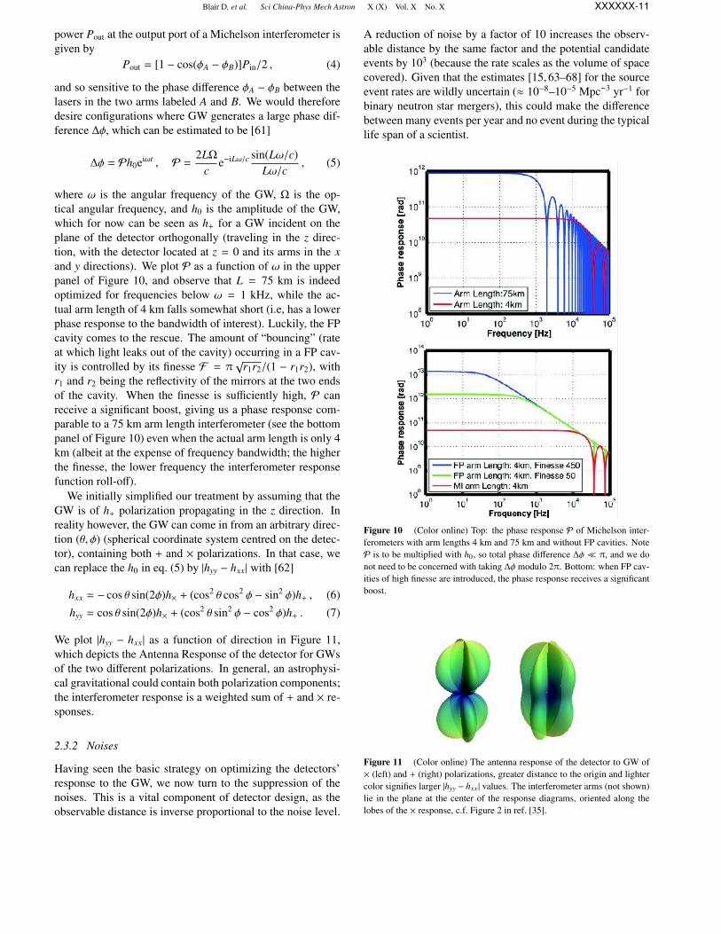
and so sensitive to the phase difference φA − φB between thelasers in the two arms labeled A and B. We would thereforedesire configurations where GW generates a large phase dif-ference ∆φ, which can be estimated to be [61]
∆φ = Ph0eiωt , P =2LΩ
ce−iLω/c sin(Lω/c)
Lω/c, (5)
where ω is the angular frequency of the GW, Ω is the op-tical angular frequency, and h0 is the amplitude of the GW,which for now can be seen as h+ for a GW incident on theplane of the detector orthogonally (traveling in the z direc-tion, with the detector located at z = 0 and its arms in the xand y directions). We plot P as a function of ω in the upperpanel of Figure 10, and observe that L = 75 km is indeedoptimized for frequencies below ω = 1 kHz, while the ac-tual arm length of 4 km falls somewhat short (i.e, has a lowerphase response to the bandwidth of interest). Luckily, the FPcavity comes to the rescue. The amount of “bouncing” (rateat which light leaks out of the cavity) occurring in a FP cav-ity is controlled by its finesse F = π
√r1r2/(1 − r1r2), with
r1 and r2 being the reflectivity of the mirrors at the two endsof the cavity. When the finesse is sufficiently high, P canreceive a significant boost, giving us a phase response com-parable to a 75 km arm length interferometer (see the bottompanel of Figure 10) even when the actual arm length is only 4km (albeit at the expense of frequency bandwidth; the higherthe finesse, the lower frequency the interferometer responsefunction roll-off).
We initially simplified our treatment by assuming that theGW is of h+ polarization propagating in the z direction. Inreality however, the GW can come in from an arbitrary direc-tion (θ, φ) (spherical coordinate system centred on the detec-tor), containing both + and × polarizations. In that case, wecan replace the h0 in eq. (5) by |hyy − hxx| with [62]
hxx = − cos θ sin(2φ)h× + (cos2 θ cos2 φ − sin2 φ)h+ , (6)
hyy = cos θ sin(2φ)h× + (cos2 θ sin2 φ − cos2 φ)h+ . (7)
We plot |hyy − hxx| as a function of direction in Figure 11,which depicts the Antenna Response of the detector for GWsof the two different polarizations. In general, an astrophysi-cal gravitational could contain both polarization components;the interferometer response is a weighted sum of + and × re-sponses.
2.3.2 Noises
Having seen the basic strategy on optimizing the detectors’response to the GW, we now turn to the suppression of thenoises. This is a vital component of detector design, as theobservable distance is inverse proportional to the noise level.
A reduction of noise by a factor of 10 increases the observ-able distance by the same factor and the potential candidateevents by 103 (because the rate scales as the volume of spacecovered). Given that the estimates [15, 63–68] for the sourceevent rates are wildly uncertain (≈ 10−8–10−5 Mpc−3 yr−1 forbinary neutron star mergers), this could make the differencebetween many events per year and no event during the typicallife span of a scientist.
Figure 10 (Color online) Top: the phase response P of Michelson inter-ferometers with arm lengths 4 km and 75 km and without FP cavities. NoteP is to be multiplied with h0, so total phase difference ∆φ π, and we donot need to be concerned with taking ∆φ modulo 2π. Bottom: when FP cav-ities of high finesse are introduced, the phase response receives a significantboost.
Figure 11 (Color online) The antenna response of the detector to GW of× (left) and + (right) polarizations, greater distance to the origin and lightercolor signifies larger |hyy − hxx | values. The interferometer arms (not shown)lie in the plane at the center of the response diagrams, oriented along thelobes of the × response, c.f. Figure 2 in ref. [35].

Blair D, et al. Sci China-Phys Mech Astron X (X) Vol. X No. X XXXXXX-12
When viewed from the basis of the three classes of inter-ferometer components shown in Figure 9, the major types ofnoises are displacement noises that enter into the mechanicalcomponents, the optical noises that arise in the optics, whilethe electrical noises emerge in the electronics. Figure 12 is acartoon depiction of these three types of noises and the placeswhere they creep into our measurements, and Figure 13 isthe Advanced LIGO Livingston noise budget, broken downinto contributions from the various different types of noisesources. We will discuss the displacement and optical typesin some detail below.
1. Displacement noises This is the uncertainty in thedistance between the two mirrors in Figure 12 due to mechan-ical excitations: (1) seismic motions that move the mirrors,(2) thermal noise, and (3) Newtonian gravity noise.
(1) To reduce seismic noise, one can place the mirrorson active platforms controlled by appropriate feedback sys-tems [69,70]. These are quite good at reducing the lower fre-quency seismic noises. One can then place the mirror withina damped harmonic oscillator as an additional passive iso-lation [71, 72], which provides vibration isolation above itsresonant frequency. Let d and D denote the displacement ofthe mirror and the ground respectively, then we can lowerthe peak ratio for d/D by tuning the damping coefficient
Figure 12 (Color online) The three types of noises and the places wherethey enter into the measurements.
Figure 13 (Color online) A typical Advanced LIGO noise budget, brokendown into different noise components.
(the downside is that isolation at non-peak frequencies getsworse), make the d/D curve drop with a steeper inclinationinto higher seismic motion frequencies by making the oscil-lator multi-staged [73] (the price to pay is the appearanceof multiple resonant peaks), and produce better isolation athigher frequencies by lowering the resonant frequency (thisis more complex to realize). In practice, the pros and consof these measures are weighed, and a combination of them isdeployed [51, 74–82].
(2) A host of thermal noises affect the mirror, consisting ofa bulk substrate and layers of optical coating material, as wellas the suspension wires/fibers (the mirrors are suspended aspendulums, forming part of a multi-stage harmonic oscilla-tor and can move freely in response to GW [35]). There areseveral types of thermal noises: Brownian motion presentsitself as thermally-excited body modes in the mirror and pen-dulum modes in the suspension fibers; thermo-elastic noiseis the mirror motion and displacement caused by temperaturefluctuations [83]; temperature fluctuations also causes fluc-tuations of the mirror refractive index, termed the thermo-refractive noise (which can in fact be made to largely cancelwith the thermo-elastic noise [84, 85]). The choice of mir-ror and suspension fiber material is important for the sup-pression of the remaining thermal noises. Present day sub-strate material such as fused silica, sapphire and silicon havevery good thermal properties. However, the mirror coatingmaterial, chosen for their optical and not mechanical/thermalqualities, usually fare worse in this respect, and needs to becarefully selected and the coating layer structure closely scru-tinized [83,86–95]. Indeed, the Brownian noise of the opticalcoating constitutes one of the limiting noise sources for Ad-vanced LIGO.
(3) The Newtonian gravity noise is also called the grav-ity gradient noise. It is the motion induced via gravitationalcoupling by the mass density fluctuations around the detec-tor, with the dominant type being seismic surface wave (thisdiffers from the seismic noise discussed earlier in the typeof force through which the seismic motions affect the testmass mirrors). Some strategies for mitigating this noise in-clude [96, 97]: going to quiet places (e.g. underground asKAGRA does), feedforward subtraction, or passive reductionby shaping local topography.
2. Optical noises These are optics-related noises thatcontaminate the readout signal. The major subclasses of opti-cal noises are fundamental quantum noises (shot noise, radia-tion pressure noise), laser technical noises (frequency and in-tensity noises), modulation noises, and scattered light noise.In Figure 13, we plot the noise budget of the Advanced LIGOdetector from the Livingston L1 interferometer, noting in par-ticular that the quantum (shot) noises dominate at higher fre-quencies. We delve into this more deeply below.
Shot and radiation pressure noise originates directly fromthe quantum nature of light. The number of photons arrivingat a photodetector over any period of time is statistically un-certain, and can be approximately modeled using a Poisson
Blair D, et al. Sci China-Phys Mech Astron X (X) Vol. X No. X XXXXXX-13
distribution. This results in a statistical fluctuation in outputpower Pout and increases the noise relative to the GW signalproportional to
√Pout. Let iDC be the DC photocurrent (pro-
portional to the mean number of photons per second), andishot be the shot noise current (essentially the standard devia-tion of fluctuations in the number of photons). Following thesame logic, ishot is then proportional to
√iDC. One notices
that iDC increases faster than ishot ∼√
iDC as we turn up thelaser power, and so the percentage uncertainty in Pout drops.It is therefore beneficial to use more powerful lasers, as far asthe shot noise is concerned.
Simply turning up the laser power has unfortunate side ef-fects, however. The laser exerts pressure on the mirrors (aback action), so higher-power induced greater photon num-ber fluctuation in the arm cavities would create a fluctua-tion of the back action force, causing unwanted motion ofthe mirror (i.e., displacement noise), so-called radiation pres-sure noise. A caveat is that the radiation pressure noise ofthe input laser itself is actually the same in both arms of theinterferometer and is cancelled in the signal, it is in fact thecoupling between the stable laser light and the vacuum fluc-tuation injected from the dark port that results in a differen-tial power fluctuation and subsequently noise in the detectorreadout [98–101]. Nevertheless, increased laser power pro-duces more pronounced fluctuations of this type. An optimaltrade-off between the shot and radiation pressure noises canbe achieved by tuning the laser power, and the lower limitto the strain noise that can be thus obtained is named the“Standard Quantum Limit” [102]. In addition, the mirrorsof the interferometer absorb some of the laser light, typically0.1%–0.5% of the total input power, resulting in a changein the optical characteristics (effective focal lengths and radiiof curvature) of the mirrors [103, 104] that negatively impactinterferometer performance. This is typically ably managedthrough adaptive optical techniques [105].
2.4 Advanced LIGO
Lastly, we offer an overview of the Advanced LIGO projectand an update on its current status. The Advanced LIGOis a complete redesign and rebuild of the LIGO interferom-eters. Some of the new features added include a signal-recycling [106, 107] mirror operated in a resonant sidebandextraction mode [108, 109]. This allows to tune the inter-ferometers’ frequency response. For example, interferome-ters are normally operated in broadband mode, but can betuned to a narrow-band detector with increased sensitivitiesat specific narrow higher frequency bands (http://lhocds.ligo-wa.caltech.edu:8000/advligo/GWINC). Also, the laser powerhas been increased from initial LIGO’s 10 W to 200 W to re-duce shot noise, and the test mass mirrors have become larger(34 cm for Advanced LIGO as compared to 25 cm for initialLIGO) and heavier (increased to 40 kg from 11 kg) to sup-press thermal and radiation pressure noises respectively. Thesteel wires suspending the mirrors have been replaced with
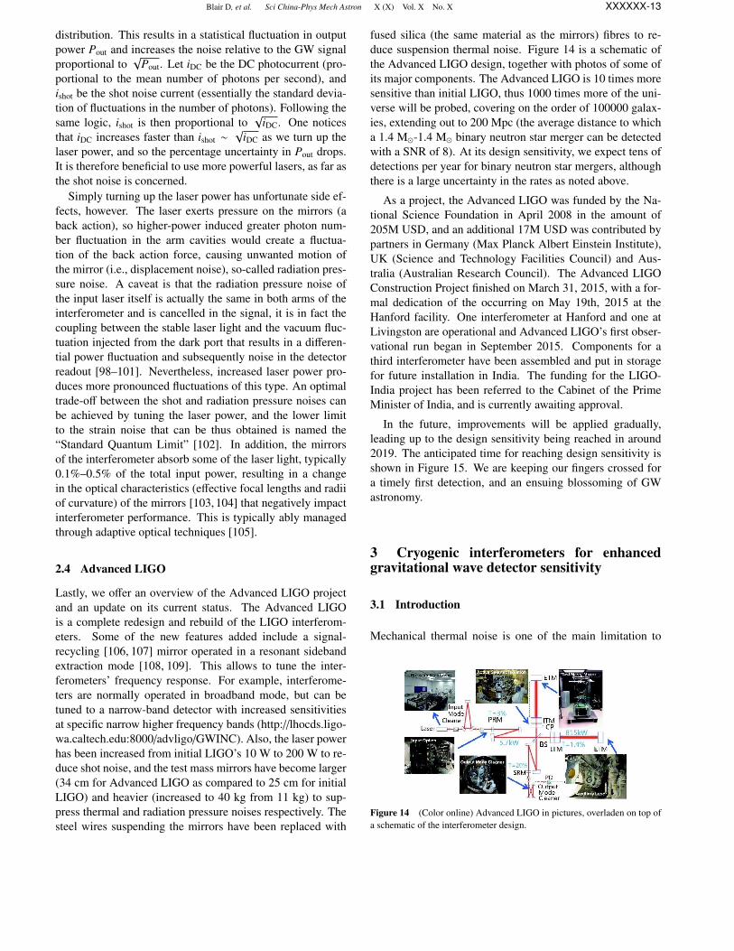
fused silica (the same material as the mirrors) fibres to re-duce suspension thermal noise. Figure 14 is a schematic ofthe Advanced LIGO design, together with photos of some ofits major components. The Advanced LIGO is 10 times moresensitive than initial LIGO, thus 1000 times more of the uni-verse will be probed, covering on the order of 100000 galax-ies, extending out to 200 Mpc (the average distance to whicha 1.4 M-1.4 M binary neutron star merger can be detectedwith a SNR of 8). At its design sensitivity, we expect tens ofdetections per year for binary neutron star mergers, althoughthere is a large uncertainty in the rates as noted above.
As a project, the Advanced LIGO was funded by the Na-tional Science Foundation in April 2008 in the amount of205M USD, and an additional 17M USD was contributed bypartners in Germany (Max Planck Albert Einstein Institute),UK (Science and Technology Facilities Council) and Aus-tralia (Australian Research Council). The Advanced LIGOConstruction Project finished on March 31, 2015, with a for-mal dedication of the occurring on May 19th, 2015 at theHanford facility. One interferometer at Hanford and one atLivingston are operational and Advanced LIGO’s first obser-vational run began in September 2015. Components for athird interferometer have been assembled and put in storagefor future installation in India. The funding for the LIGO-India project has been referred to the Cabinet of the PrimeMinister of India, and is currently awaiting approval.
In the future, improvements will be applied gradually,leading up to the design sensitivity being reached in around2019. The anticipated time for reaching design sensitivity isshown in Figure 15. We are keeping our fingers crossed fora timely first detection, and an ensuing blossoming of GWastronomy.
3 Cryogenic interferometers for enhancedgravitational wave detector sensitivity
3.1 Introduction
Mechanical thermal noise is one of the main limitation to
Figure 14 (Color online) Advanced LIGO in pictures, overladen on top ofa schematic of the interferometer design.

Blair D, et al. Sci China-Phys Mech Astron X (X) Vol. X No. X XXXXXX-14
Figure 15 (Color online) The anticipated sensitivity progression for Ad-vanced LIGO over the next five years. Taken from ref. [110].
the sensitivity of laser interferometer GW detectors such asLIGO [38], Virgo [111], GEO [40] and KAGRA [51]. Thisdisplacement noise is a direct consequence of the fluctuation-dissipation theorem according to which any mechanical sys-tem affected by some form of energy dissipation will bedriven by a stochastic force whose amplitude depends onthe system temperature and the dissipation amplitude [112].While the total random motion of the system should agreewith the well-known expression E = 1/2kT , the spectral dis-tribution of this displacement will depend on the details of thedissipation mechanism and of the mechanical response of thesystem to the stochastic force. As a general rule the motionof a mechanical system with lower losses (i.e. larger mechan-ical quality factor) will be more concentrated at the resonantfrequencies of the system while the motion amplitude out ofthe resonances will be smaller.
The mirrors of laser interferometer GW detectors as wellas their suspensions are mechanical system affected by en-ergy losses and as such are subject to thermal noise [113]. Inthe case of the mirror suspension the dominant effect are themechanical losses in the fibers used to suspend the mirror aswell as any loss in the contact points between the fibers andthe mirror itself. The case of the mirrors is more complexand several mechanism have been considered. The mechan-ical losses inside the coatings providing the required mirrorreflectivity are the dominant effect [92,114] but in some casesalso the losses inside the substrate materials can be impor-tant [115, 116]. Thermo-elastic damping is one of the funda-mental loss mechanism affecting any type of material. It isrelated to the dissipation of energy taking place when a mate-rial vibrates and heat is transferred from one place to anotherin the system [113]. This noise, known as thermo-elasticnoise, increase with the temperature and increases with thethermal expansion coefficient [117]. It can be a major limi-tation to the sensitivity of laser interferometers depending onthe material used and the operating temperature. Since theinterferometer is sensing the optical properties of the mirror,opto-mechanical effects such as the variation in the index ofrefraction of the coating or of the substrate due to the tem-perature fluctuations is also a potential noise source whose
amplitude depends on the mirror temperature [118]. Figure16 shows the Advanced Virgo sensitivity [111] and the im-pact of the various type of thermal noises.
In order to reduce the thermal noise in laser interferome-ter GW detectors several approaches have been pursued. Ingeneral one can reduce the effect of thermal noise by build-ing laser interferometer with longer arms, heavier mirrors andlarger laser beams, but this will certainly impact the cost. Asa consequence research has been conducted to reduce the fric-tion on mirror suspension adopting the so called monolithicdesign, where the wire suspending the mirror are fibers madeof the same material as the mirror substrates (typically fusedsilica) and soldered to the latter. On the other side a lot ofresearch has been done to study and reduce the losses in thematerials composing the mirror substrate and the mirror coat-ing. So far the reference solution has been to use substratesmade of high quality fused silica [116]. As for the coating thebest solution found so far is to use a multilayer stack made offused silica and titania dope tantala layers since this mini-mize both mechanical and optical losses [89, 91]. An alter-native approach is to reduce thermal noise by operating theinterferometer mirror at cryogenic temperature i.e. decreas-ing the temperature from 300 K to about 20 K. The latter isthe solution being pursued by the KAGRA project [51] andalso envisaged by the Einstein Telescope (ET) [119]. In therest of this paper we briefly introduce the main challengesthat have to be faced to operate an interferometer at cryo-genic temperature. We then describe the present design forthe cryogenic mirrors and suspensions of KAGRA. Finallywe briefly describe the approach envisaged by the ET.
3.2 The cryogenic challenges
The general argument that by reducing the mirror temper-ature from 300 K to 20 K thermal noise will be reducedby about a factor about four does not applies since the
Figure 16 (Color online) Advanced Virgo design sensitivity. Coating ther-mal noise is the limiting factor over a large part of the frequency band. Sub-strate thermal noise and coating thermos-optic noise are also shown.

Blair D, et al. Sci China-Phys Mech Astron X (X) Vol. X No. X XXXXXX-15
amplitude of mechanical losses inside materials are usuallytemperature dependent. For instance it is well know that me-chanical losses inside bulk fused silica increase at low tem-perature [120]. A somewhat similar increase has been seenin optical coatings made of SiO2, Ta2O5 and titania dopedTa2O5 even if in the case of coatings different behaviors havebeen observed [121, 122].
On the other hand mechanical losses in crystalline materi-als tend to decrease at low temperature [123]. For this rea-son materials such as sapphire and silicon look promising asthey can be produced in large size. So far the size is some-what limited by the optical properties. In fact both in thecase of silicon and of sapphire it has not been possible toachieve the level of optical absorption obtained in fused silica(nowadays well below 1 ppm/cm). In the case of Czochralskigrow silicon the absorption is in the range of several 100’sppm/cm. For floating zone grown silicon, absorption as lowas 5 ppm/cm has been measured but size is limited to about10 cm diameter [124]. In the case of sapphire the best ab-sorption is around 30 ppm/cm with sizes in the range of 20cm diameter [125]. The bottom line is that, at present, aninterferometer operated at low temperature will have to usesmaller mirror compared to the 35 cm diameter fused silicamirrors that are used at room temperature. As a consequencethe laser beam size will have to be smaller and so the ther-mal noise, which increase as 1/
√beamsize will tend to in-
crease [92]. As an example Advanced LIGO and AdvancedVirgo will have the beam size on the mirrors in the range of5 to 6 cm while KAGRA will use a beam size of 3.5 cm.
One of the main challenge when attempting to build acryogenic interferometer is the delicate compromise to befound between the requirement of having low mechanicallosses in the mirror suspension and the need to efficiently ex-tract the heat from the mirror in order to cool it down. In thisregard the optical absorption in the mirror plays a crucial rolesince it determines the heat to be extracted. The mechanicallosses in the suspension is the other crucial parameter. Thegoal is to find a monolithic suspensions with good mechani-cal losses at low temperature and which allow to extract theheat from the mirror. The vibrations from the cooling systemis one of the other challenges. The two cooling techniquesconsidered so far are the use of He circulation or the use ofpulse tube cryo-coolers. Both are potential source of vibra-tions even if in general pulse tube are noisier unless specialdesign is used. The use of He circulation raises the questionof safety especially if the detector is located underground asit is the case for KAGRA and for the ET. Finally the cool-ing time is also a challenge for a cryogenic interferometer asit determines the down time for the detector maintenance orrepair. Apart from the interventions during the detector com-missioning phase which might require to heat up the mirror,according to the estimate of the water adsorption by mirrorsurface, it will be required to heat up the mirrors at least oncea year during the operation phase. For this reason the mini-mization of the cooling time is very important.
3.3 The KAGRA solutions
The KAGRA detector currently being built in the Kamiokamine in Japan [51, 126], will be the first km scale laser in-terferometer GW detector, whose mirrors will be operated atcryogenic temperature. The goal is to maintain their temper-ature at 20 K. The mirror substrates will be made of sapphirewhile amorphous silica and tantala pentoxide layers will beused for the high reflectivity coating. The sapphire crystalssubstrates will be 22 cm diameter and 15 cm thick. The pol-ishing of a test sample has shown that is possible to achieveflatness rms below 1 nm as it is the case for fused silicasubstrates [125]. The most critical parameter is the absorp-tion in the sapphire which is required to be 30 ppm/cm (thelarge crystals received so are about a factor of two above thisvalue).
The KAGRA laser power will deliver 180 W at a wave-length of 1064 nm. Assuming 80 W entering the recyclingcavity and a recycling gain of 10, the power transmittedthrough the Fabry-Perot input mirrors will be 400 W [127].If 30 ppm/cm are absorbed, the heat deposited in the mir-rors will be 0.4 W. This is the power to be extracted in thesteady state to keep the mirror at 20 K. In order to do so thecryostat design includes two inner shields: an outer one at80 K and an inner one at 8 K (see Figure 17 [128]). Fourcryo-coolers will be used. The first stages of the cryo-coolersare devoted to the cooling of the outer shield. Two of thecryo-cooler second stages cool the inner shield and the othertwo cool the mirror payload itself. This design should allowto extract the amount of power deposited by the laser in themirrors and cool down the mirror to 20 K provided a suffi-ciently heat conduction path is made between the mirror andthe cryo-coolers. In addition two 5 m long cryogenic ductsallow the laser beam to enter the cryostat and while reducingthe 300 K radiation input to the mirror by a factor of a thou-sand compared to the input one would have from the tube inthe absence of the ducts [129].
The mirrors will be suspended by means of a monolithicsuspension made of sapphire (see Figure 17 [130]). As ex-plained in the previous section, its design is primarily drivenby the need to cool down the mirror while keeping its thermalnoise as low as possible. The compromise has been made tochoose sapphire fibers 35 cm long and 1.6 mm in diameterwith a nail head at both ends [131]. The lower fiber heads areattached to sapphire prisms (called ears) their selves attachedto the side of the mirrors by hydroxide catalysis bonding. Theprism shape is such that the fiber bending point is slightlyabove the mirror center of mass to avoid instabilities. Ontheir upper end the fiber heads are bonded to sapphire bladesprings attached to the suspension upper stage (so called in-termediate mass). The sapphire blades are there to providesome compliance in the vertical direction and compensate forany difference in the fiber lengths. This design allows lower-ing the vertical resonance of the suspension to about 15 Hz.Both fiber ends are bonded by means of a thin Indium inter-

Blair D, et al. Sci China-Phys Mech Astron X (X) Vol. X No. X XXXXXX-16
mediate layer. The indium bonding has been chosen since itallows debonding in case the fiber breaks. Extensive studieswere performed to verify the strength, thermal conductivityand mechanical quality factor of the bondings. The fibers me-chanical quality factor was measured and found to be around107 at 20 K a value which allows reaching the thermal noiserequirements. The fibers thermal conductivity was measuredto be larger than 5500 W/(m · K) [131] and so sufficient toextract the heat provided the diameter of 1.6 mm is used. Acomplete prototype of the monolithic sapphire payload is cur-rently being built [132].
The cooling time is also an important parameter since themirrors will have to be heated up and cooled down once ayear to remove the water deposited on the optical surface due
Figure 17 (Color online) The configuration of the cryostat for KAGRA(top) and the design of the sapphire monolithic suspension to suspend thesapphire mirror inside the cryostat.
to adsorption. Radiation cooling will allow to reach 150 K.Below 150 K the efficiency of radiation cooling becomes in-sufficient and another methods should be used to extract theheat. Several solutions have been considered. One is to usea heat switch, i.e. something similar to a finger moved re-motely and establishing a thermal contact between the cryo-cooler and the mirror. This reliability of the switch is themain concern of this solution since the thermal contact is un-certain as well as the risk of having such a switch stackedunder vacuum at cryogenic temperature. Another option is touse He as thermal exchange gas. While efficient, this tech-nique, which was used in resonant bar detectors, requires toconfine the He inside the cryostat in order to be able to pumpit out after cooling is completed. This requires to have re-motely controlled doors closing the two beam accesses to thecryostat. Again the risk connected with having these rela-tively large pieces of hardware moving under vacuum at cryo-genic temperature make this solution difficult to implement.Finally the option of optical cooling was considered; whilebeing promising its efficiency is still too far from the require-ment. In conclusion KAGRA will use permanent heat linksconnecting the cryo-coolers with the payload recoil masses(see Figure 17). It should be noted that these permanent heatlinks will be required anyway to extract the heat in the steadystate. Moreover, in order to accelerate the cooling time, it isplanned to coat all the payload (with the exception of the mir-ror, of course) with diamond like carbon (DLC). Accordingto the simulations this solution allows increasing the radiationcooling efficiency and thus reducing the total cooling timefrom nearly two months to 39 d. Experimental tests donewith a half size prototype of the payload coated with DLCconfirmed the validity of the simulation [129].
The heat links are a potential path for the transmission ofthe cryostat vibrations. This is one of the main challengewhenever cryostats are used in conjunction with an apparatusrequiring a very low level of vibrations. To study this effectthe cryostat vibration have been measured at the factory andcombined with the expected seismic noise at the site (which isconsiderably lower than the one at the factory). The estimateof the cryostat vibrations is then used as input in a mechani-cal model of the heat links combined with a model of the sus-pended payload to estimate the mirror vibrations. The simu-lations show that even if the heat links are connected to therecoil mass of the intermediate mass, and so not directly con-nected to the mirror, several of the cryostat vibration peakscan limit the interferometer displacement noise. The modelshows that this effect can be reduced below the noise require-ment if the heat links go through another mass seismicallyisolated independently from the main mirror. The effect ofthis mass is to short circuit the heat links vibrations [133]. Inthis area more research and development will be needed.
By using these solutions, the KAGRA project is plannedto reach the sensitivity shown in Figure 18. This sensitivityshould allow detecting the coalescence of neutron stars up todistances of about 150 Mpc. The main difference with the

Blair D, et al. Sci China-Phys Mech Astron X (X) Vol. X No. X XXXXXX-17
Figure 18 (Color online) The planned sensitivity for KAGRA. Thanks tothe reduction of thermal noise, the quantum noise is the main limitation overthe frequency band.
sensitivity of laser interferometer GW detectors operated atroom temperature is that quantum noise is the limiting factorover most of the detector bandwidth.
3.4 The Einstein Telescope approach
The ET is a third generation GW detector for which the con-struction of a new research infrastructure is being proposedin Europe [119]. The goal is to improve by one order of mag-nitude in sensitivity over the detectors currently being pre-pared (Advanced LIGO, Advanced Virgo and KAGRA). Tothis purpose a new underground infrastructure able to hostthree nested laser interferometers with arms 10 km in lengthis proposed. Other ingredients of this new detector will belarger mirrors, larger laser beams and the use of frequency de-pendent squeezed states of light. The use of cryogenics to op-erate the interferometer at low temperature is also part of theET conceptual design but the approach is different. In order tocope with the contrast between the need of higher laser powerto improve the sensitivity at high frequencies and the use ofcryogenics to reduce the thermal noise, more relevant in thelow frequencies, the ET design foresees the combination oftwo interferometers covering two different frequency bands.The principle is known as the xylophone approach [134]. Themain characteristics of the two interferometers are summa-rized in Table 3 (extracted from ref. [119]).
The high frequency detector uses high power laser to re-duce the shot noise, large mirror masses to cope with the ra-diation pressure noise and frequency dependent squeezing toreduce further the quantum noise. Given the frequency bandof interest and the high intra-cavity laser power, this interfer-ometer is operated at room temperature.
The low frequency detector will be cryogenic and operatedat 10 K. In order to reduce the heat load in the mirror only 3W are injected into the interferometer. This will result into18 kW inside the Fabry-Perot arm cavities (to be comparedwith to about 0.5 MW in advanced detectors) thus helping thereduction of radiation pressure noise effect. The reduction ofthe intra-cavity power being insufficient to attain the desiredsensitivity it is necessary to use mirrors with very large mass(200 kg).
Table 3 Interferometer parameters of the Einstein Telescope conceptualdesign [119]
Parameter ET-D-HF Et-D-LF
Arm length 10 km 10 km
Input power (after IMC) 5000 W 3 W
Arm power 3 MW 18 kW
Temperature 290 K 10 K
Mirror material fused silica silicon
Mirror diameter/thickness 62 cm /30 cm min 45 cm/T
Mirror mass 200 kg 211 kg
Laser wavelength 1064 nm 1550 nm
SR-phase tuend (0.0) detued (0.6)
SR transmittance 10% 20%
Quantum noise suppression freq. dep. squeez. freq. dep. squeez.
Filter cavities 1 × 10 km 2 × 10 km
Squeezing level 10 dB (effective) 10 dB (effective)
Beam shape LG33 TME00
Beam radius 7.25 cm 9 cm
Scatter loss per surface 37.5 ppm 37.5 ppm
Seimic isolation SA, 8 m tall mod SA, 17 m tall
Sesmic (for f > 1 Hz) 5 × 10⁻¹⁰/m/ f 2 5 × 10⁻¹⁰/m/ f 2
Gravity gradient substraction none none
Using the Czochralski crystal growth method it is now pos-sible to obtain silicon single crystals of this mass in the shapeof cylinder with 45 cm diameter. Unfortunately these crystalsdo not have the best purity and as a consequence their opticalabsorption is in the range of several 100 s of ppm/cm. Lowerabsorption has been measured in silicon crystals grown withthe floating zone method but unfortunately their size is lim-ited to about 10 cm diameter. In both cases the optical qualityis not well known as these crystals are mainly developed forelectronic applications so that an intense R&D program is re-quired to reduce their optical absorption and to investigateoptical properties such as homogeneity, birefringence, inter-nal defects etc.
On Figure 19 the sensitivity of each ET detector is showntogether with the overall sensitivity of the combined detec-tors. The design allows to decrease the best sensitivity in therange of a few parts in 10−24/
√Hz and to extend the band
down to a few Hz. The latter result could be obtained thanksto the cryogenic operation.
3.5 Perspectives in the use of cryogenics for gravitationalwave detectors
Despite the research performed and the progresses made,thermal noise continue to be one of the fundamental limi-tation to the sensitivity of laser interferometer GW detectors.The use of cryogenics is the most direct way to reduce it butseveral challenges have to be faced.
The KAGRA project will be the first laser interferometer

Blair D, et al. Sci China-Phys Mech Astron X (X) Vol. X No. X XXXXXX-18
Figure 19 (Color online) Sensitivity of the ET in the ‘xylophone’ configu-ration.
with km-scale arms to be operated at cryogenic temperature.As a consequence several issues were studied and a designbased on a monolithic sapphire suspension is available. Theforthcoming operation of KAGRA will not only increase thecapability of the worldwide GW detectors network but willalso pave the road toward the realization of the ET.
Both studies show that the mirrors substrate material andin particular its optical absorption plays a crucial role as it setsthe refrigeration needs. Both sapphire and silicon requires anintense R&D program to improve their optical quality. TheET design sensitivity somehow assumes that this issue willbe solved. It is interesting to note that even in this case, thecoating thermal noise will limit the high frequency detector.This noise will also play a role in the low frequency detectorunless the coating mechanical losses at low temperature willbecome comparable to the one reached today at room tem-perature. In this regards the recent development of crystallinecoatings with lower mechanical losses both at room temper-ature and at cryogenic temperature seems very promising toreduce further the thermal noise limitation [135].
4 Detecting nanohertz gravitational waveswith pulsar timing arrays
Complementary to ground-based laser interferometers, pul-sar timing array experiments are being carried out to searchfor nanohertz GWs. Using the world’s most powerful ra-dio telescopes, three major international collaborations havecollected ∼10-year high precision timing data for tens of mil-lisecond pulsars. In this section we give an overview onpulsar timing experiments, GW detection in the nanohertzregime, and recent results obtained by various timing arrayprojects.
4.1 Introduction
One hundred years ago, Albert Einstein completed his gen-eral theory of relativity, radically revolutionizing our under-standing of gravity. In this theory, gravity is no longer a force,
but instead an effect of spacetime curvature. The mass andenergy content of spacetime creates curvature that in turn dic-tates the behavior of objects in spacetime. Generally speak-ing, when a massive object is accelerating, it produces curva-ture perturbations that propagate at the speed of light. Suchripples in the fabric of spacetime are called GWs.
Forty years ago, Hulse and Taylor [7] discovered thebinary-pulsar system PSR B1913+16. Subsequent observa-tions in the following years showed that its orbital period wasgradually decreasing, at a rate that was entirely consistentwith that predicted by general relativity as a result of grav-itational radiation [136, 137]. This provided the most con-vincing evidence of the existence of GWs and earned Hulseand Taylor the Nobel prize in Physics in 1993.
It was realized in late 1970s that precision timing obser-vations of pulsars can be used to detect very low frequencyGWs (∼ 10−9–10−7 Hz; [138, 139]). Based on a calculationby Estabrook & Wahlquist [140] for the GW detection usingDoppler spacecraft tracking, for which the principle is sim-ilar to pulsar timing, Detweiler [139] explicitly showed that“a GW incident upon either a pulsar or the Earth changesthe measured frequency and appears then as a anomalousresidual in the pulse arrival time”. In 1983, Hellings &Downs [141] used timing data from four pulsars to constrainthe energy density of any stochastic background to be . 10−4
times the critical cosmological density at . 10−8 Hz (see,refs. [142, 143] for similar results). Almost simultaneouslyto these works, Backer et al. [144] discovered the first mil-lisecond pulsar PSR B1937+21. Because of its far better ro-tational stability than any previously known pulsars and rel-atively narrower pulses, timing observations in the follow-ing years improved the limit on stochastic backgrounds veryquickly and by orders of magnitude [145–148].
Measurements with a single pulsar can not make definitedetections of GWs whose effects may be indistinguishablefrom other noise processes such as irregular spinning of thestar itself. By continued timing of an array of millisecondpulsars, i.e., by constructing a pulsar timing array (PTA),GWs can be searched for as correlated signals in the tim-ing data. Hellings & Downs [141] first did such a correla-tion analysis to put limits on stochastic backgrounds. Ro-mani [149] and Foster & Backer [150] explored the greaterscientific potential of PTA experiments: (1) searching forGWs; (2) providing a time standard for long time scales; and(3) detecting errors in the solar system ephemerides.
There are three major PTAs currently operating: the ParkesPTA (PPTA (http://www.atnf.csiro.au/research/pulsar/ppta/);[151, 152]) was set up in 2004 using the Parkes ra-dio telescope in Australia; the European PTA (EPTA(http://www.epta.eu.org/); [153]) was initiated in 2004/2005and makes use of telescopes in France, Germany, Italy,the Netherlands and the UK; and the North AmericanNanohertz Observatory for Gravitational Waves (NANOGrav(http://nanograv.org/)); [154]) was formed in 2007 and car-ries out observations with the Arecibo and Green Bank
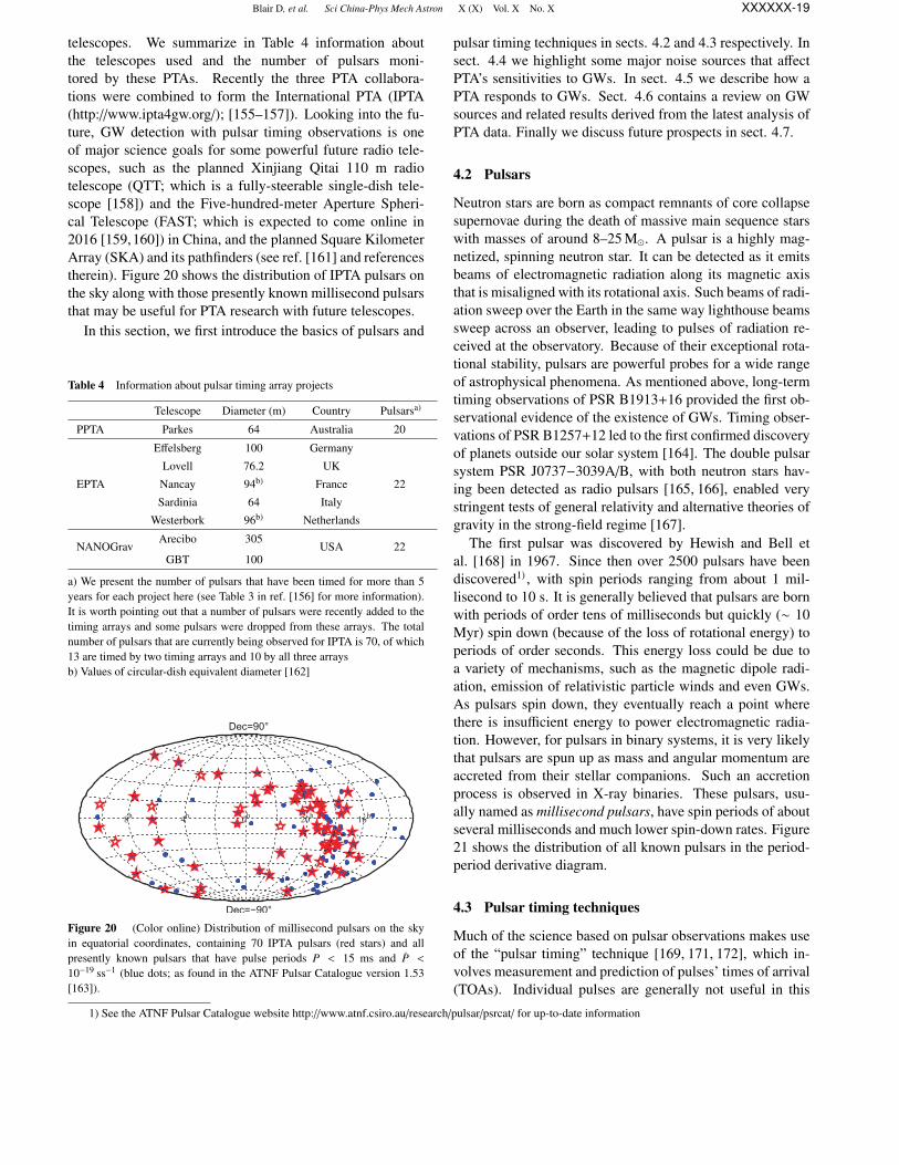
Blair D, et al. Sci China-Phys Mech Astron X (X) Vol. X No. X XXXXXX-19
telescopes. We summarize in Table 4 information aboutthe telescopes used and the number of pulsars moni-tored by these PTAs. Recently the three PTA collabora-tions were combined to form the International PTA (IPTA(http://www.ipta4gw.org/); [155–157]). Looking into the fu-ture, GW detection with pulsar timing observations is oneof major science goals for some powerful future radio tele-scopes, such as the planned Xinjiang Qitai 110 m radiotelescope (QTT; which is a fully-steerable single-dish tele-scope [158]) and the Five-hundred-meter Aperture Spheri-cal Telescope (FAST; which is expected to come online in2016 [159,160]) in China, and the planned Square KilometerArray (SKA) and its pathfinders (see ref. [161] and referencestherein). Figure 20 shows the distribution of IPTA pulsars onthe sky along with those presently known millisecond pulsarsthat may be useful for PTA research with future telescopes.
In this section, we first introduce the basics of pulsars and
Table 4 Information about pulsar timing array projects
Telescope Diameter (m) Country Pulsarsa)
PPTA Parkes 64 Australia 20
Effelsberg 100 Germany
Lovell 76.2 UK
EPTA Nancay 94b) France 22
Sardinia 64 Italy
Westerbork 96b) Netherlands
NANOGravArecibo 305
USA 22GBT 100
a) We present the number of pulsars that have been timed for more than 5years for each project here (see Table 3 in ref. [156] for more information).It is worth pointing out that a number of pulsars were recently added to thetiming arrays and some pulsars were dropped from these arrays. The totalnumber of pulsars that are currently being observed for IPTA is 70, of which13 are timed by two timing arrays and 10 by all three arraysb) Values of circular-dish equivalent diameter [162]
8h 4h 0h 20h 16h
Dec=−90°
Dec=90°
Figure 20 (Color online) Distribution of millisecond pulsars on the skyin equatorial coordinates, containing 70 IPTA pulsars (red stars) and allpresently known pulsars that have pulse periods P < 15 ms and P <
10−19 ss−1 (blue dots; as found in the ATNF Pulsar Catalogue version 1.53[163]).
pulsar timing techniques in sects. 4.2 and 4.3 respectively. Insect. 4.4 we highlight some major noise sources that affectPTA’s sensitivities to GWs. In sect. 4.5 we describe how aPTA responds to GWs. Sect. 4.6 contains a review on GWsources and related results derived from the latest analysis ofPTA data. Finally we discuss future prospects in sect. 4.7.
4.2 Pulsars
Neutron stars are born as compact remnants of core collapsesupernovae during the death of massive main sequence starswith masses of around 8–25 M. A pulsar is a highly mag-netized, spinning neutron star. It can be detected as it emitsbeams of electromagnetic radiation along its magnetic axisthat is misaligned with its rotational axis. Such beams of radi-ation sweep over the Earth in the same way lighthouse beamssweep across an observer, leading to pulses of radiation re-ceived at the observatory. Because of their exceptional rota-tional stability, pulsars are powerful probes for a wide rangeof astrophysical phenomena. As mentioned above, long-termtiming observations of PSR B1913+16 provided the first ob-servational evidence of the existence of GWs. Timing obser-vations of PSR B1257+12 led to the first confirmed discoveryof planets outside our solar system [164]. The double pulsarsystem PSR J0737−3039A/B, with both neutron stars hav-ing been detected as radio pulsars [165, 166], enabled verystringent tests of general relativity and alternative theories ofgravity in the strong-field regime [167].
The first pulsar was discovered by Hewish and Bell etal. [168] in 1967. Since then over 2500 pulsars have beendiscovered1) , with spin periods ranging from about 1 mil-lisecond to 10 s. It is generally believed that pulsars are bornwith periods of order tens of milliseconds but quickly (∼ 10Myr) spin down (because of the loss of rotational energy) toperiods of order seconds. This energy loss could be due toa variety of mechanisms, such as the magnetic dipole radi-ation, emission of relativistic particle winds and even GWs.As pulsars spin down, they eventually reach a point wherethere is insufficient energy to power electromagnetic radia-tion. However, for pulsars in binary systems, it is very likelythat pulsars are spun up as mass and angular momentum areaccreted from their stellar companions. Such an accretionprocess is observed in X-ray binaries. These pulsars, usu-ally named as millisecond pulsars, have spin periods of aboutseveral milliseconds and much lower spin-down rates. Figure21 shows the distribution of all known pulsars in the period-period derivative diagram.
4.3 Pulsar timing techniques
Much of the science based on pulsar observations makes useof the “pulsar timing” technique [169, 171, 172], which in-volves measurement and prediction of pulses’ times of arrival(TOAs). Individual pulses are generally not useful in this
1) See the ATNF Pulsar Catalogue website http://www.atnf.csiro.au/research/pulsar/psrcat/ for up-to-date information

Blair D, et al. Sci China-Phys Mech Astron X (X) Vol. X No. X XXXXXX-20
10−3
10−2
10−1
100
101
10−22
10−20
10−18
10−16
10−14
10−12
10−10
P (s)
P(ss−1)
103 yr
105 yr
107 yr
1014G
1012G
1010G
108 G
109 yr
Figure 21 (Color online) The period (P) vs. period derivative (P) diagramfor all known pulsars (black dots; data taken from the ATNF Pulsar Cat-alogue version 1.53). Red (grey) circles represent the millisecond pulsarscurrently being timed by the IPTA project. Also shown are lines of constantcharacteristic age τ = P/2P (dash) assuming that pulsars are spinning downsolely because of magnetic dipole radiation [169], and of constant inferredsurface magnetic field B0 = 3.2 × 10¹⁹
√PP Gauss (solid; [170]). Two dis-
tinct populations are apparent in this diagram: (a) normal pulsars, with P ∼0.1–4 s and B0 ∼ 1011–1013 Gauss; (b) millisecond pulsars, with P ∼ 3milliseconds and P ∼ 10−20 ss−1.
regard as they are unstable and mostly too weak to observe.The average pulse profile over a large number of pulses isstable for a particular pulsar at a given observing wavelength,and therefore very suitable for timing experiments.
The first step in pulsar timing is to measure the topocen-tric pulse arrival times with clocks local to the radio obser-vatories. Data collected with the telescope are de-dispersedto correct for frequency-dependent dispersion delays due tothe ionized interstellar medium. These data are then foldedwith the period derived from previous observations to formthe mean pulse profile. This profile is then correlated with astandard template, either an analytic function or simply a veryhigh signal-to-noise ratio observation, to record the pulse ar-rival time at the observatory.
The measured TOAs are further transformed to the pulseemission time via a timing model, from which the pulse phaseof emission is computed. The rotational phase φ(t) of the pul-sar as a function of time t (measured in an inertial referenceframe of the pulsar) can be represented as a Taylor series:
φ(t) = φ(t0) + f (t − t0) +12
f (t − t0)2 + · · · , (8)
where t0 is an arbitrary reference time, f = dφ/dt is thespin frequency, and f is the frequency derivative. A numberof corrections are applied when converting the topocentricTOAs to the pulsar frame. Such corrections include:
1. Clock corrections, which account for differences in theobservatory time and a realization of Terrestrial Time (e.g.,the International Atomic Time).
2. pulse delay induced by Earth’s troposphere.3. the Einstein delay, i.e., the time dilation due to changes
in the gravitational potential of the Earth, the Earth’s motion,and the secular motion of the pulsar or that of its binary sys-tem.
4. the Roemer delay, i.e., the vacuum light travel time be-tween the observatory and the solar system barycenter, andfor pulsars in binaries between the pulsar and the binary sys-tem’s barycenter.
5. Shapiro delays, i.e., gravitational time delays due to thesolar system objects and if applicable the pulsar’s companion.
6. Dispersion delays caused by the interstellar medium,the interplanetary medium and the Earth’s ionosphere.
The timing model, which describes the above correctionsand the pulsar’s intrinsic rotational behavior, predicts the ro-tational phase of the pulsar at any given time as observedfrom the solar system barycenter. Basic parameters of a pul-sar timing model include the spin period, spin-down rate,right ascension and declination of the pulsar, the dispersionmeasure (discussed later in sect. 4.4), and Keplerian orbitalparameters if the pulsar is in a binary system. MeasuredTOAs are compared with predictions based on the timingmodel, and the differences are called timing residuals. The(pre-fit) timing residual for the i-th observation is calculatedas [173]:
Ri =φ(ti) − Ni
f, (9)
where Ni is the nearest integer2) to each φ(ti). One can seethe key point in pulsar timing is that every single rotation ofthe pulsar is unambiguously accounted for over long periods(years to decades) of time.
A linear least-squares fitting procedure is carried out toobtain estimates of timing parameters, their uncertainties andthe post-fit timing residuals. In practice, this is done itera-tively: one starts from a small set of data and only includesthe most basic parameters (with values derived from previousobservations) so that it is easier to coherently track the rota-tional phase. Parameter estimates are then improved by mini-mizing the timing residuals and additional parameters can beincluded for a longer data set.
The fitting to a timing model and analysis of the timingresiduals can be performed with the pulsar timing softwarepackage TEMPO2 [171, 173, 174], which is freely availableon the internet for download (www.sf.net/projects/tempo2/).More recently, an alternative method based on Bayesian in-ference was also developed [175, 176].
4.4 Noise sources in pulsar timing data
Timing residuals generally come from two groups of con-tribution: (1) un-modelled deterministic processes, e.g., an
2) Here note that φ(t) is measured in turns equal to 2π radians

Blair D, et al. Sci China-Phys Mech Astron X (X) Vol. X No. X XXXXXX-21
unknown binary companion or a single-source GW; and (2)stochastic processes, e.g., the intrinsic pulsar spin noise anda GW background. Before the discussion of GW detectionwith PTAs, we briefly discuss some major noise processes inpulsar timing data here.
4.4.1 Radiometer noise
Radiometer noise arises from the observing system and theradio sky background (including the atmosphere, the cos-mic microwave background and synchrotron emission in theGalactic plane). It can be quantified as [169]:
σrad. ≈W
S/N≈
WS sys
S mean√
2∆νtint
√W
P −W, (10)
where W and P are the pulse width and period respectively,S/N is the profile signal-to-noise ratio, S sys is the systemequivalent flux density which depends on the system tem-perature and the telescope’s effective collecting area, S mean
the pulsar’s flux density averaged over its pulse period, ∆νand tint are the observation bandwidth and integration timerespectively. Radiometer noise can be reduced by using low-noise receivers, observing with larger telescopes, and increas-ing observing time and bandwidth. One reason to fold indi-vidual pulses to obtain an average profile is to reduce the ra-diometer noise; the reduction is equal to the square root ofthe number of pulses folded. Radiometer noise is an additiveGaussian white noise and is formally responsible for TOAuncertainties. From eq. (10), one can see that bright, fastspinning pulsars with narrow pulse profiles allow the highesttiming precision.
4.4.2 Pulse jitter noise
Pulse jitter manifests as the variability in the shape and ar-rival phase of individual pulses. The mean pulse profile is anaverage over a large number of single pulses. Although it isstable for most practical purposes, there always exists somedegree of stochasticity in the phase and amplitude of the av-erage pulse profile. Pulse jitter noise is intrinsic to the pulsaritself, and thus can only be reduced by increasing observingtime, i.e., averaging over more single pulses. Pulse jitter isalso a source of white noise, which has been found to be alimiting factor of the timing precision for a few very brightpulsars [177, 178]. For future telescopes such as FAST andSKA, jitter noise may dominate over the radiometer noise formany millisecond pulsars [160]. Improvement in the timingprecision for the brightest pulsar PSR J0437−4715 was re-cently demonstrated with the use of some mitigation methodsfor pulse jitter noise [179, 180].
4.4.3 “Timing noise”
It has long been realized that timing residuals of many pul-sars show structures that are inconsistent with TOA uncer-tainties [181,182]. Such structures are collectively referred to
as timing noise. Timing noise is very commonly seen in nor-mal pulsars and has also become more prominent in a numberof millisecond pulsars as timing precision increases and thedata span grows. The exact astrophysical origins of timingnoise are not well understood. It is mostly suggested to berelated to rotational irregularities of the pulsar and thereforeit is also usually called as spin noise [183,184]. For millisec-ond pulsars, power spectra of timing residuals can typicallybe modelled as the sum of white noise and red noise. For rednoise, a power law spectrum with a low-frequency turnoverappears to be a good approximation (see, e.g., Figure 11 inref. [151] for analyses of 20 PPTA pulsars).
The presence of red noise results in problems to the pulsartiming analysis as the standard least-squares fitting of a tim-ing model assumes time-independent TOA errors. Blandfordet al. [181] analytically showed the effects of timing noise onthe estimates of timing model parameters and suggested theuse of the noise covariance matrix to pre-whiten the data forimproved parameter estimation. More recently, Coles et al.[185] developed a whitening method that uses the Choleskydecomposition of the covariance matrix of timing residualsto whiten both the residuals and the timing model. By doingso, noise in the whitened residuals is statistically white andthe ordinary least-squares solution of a timing model can beobtained. van Haasteren & Levin [186] developed a Bayesianframework that is capable of simultaneously estimating tim-ing model parameters and timing noise spectra.
4.4.4 Dispersion measure variations
Because of dispersion due to the interstellar plasma, pulses atlow frequencies arrive later than at high frequencies. Specif-ically, this dispersion delay is given by
∆DM ≈ (4.15 ms) DM ν−2GHz, (11)
where νGHz is the radio frequency measured in GHz, and dis-persion measure (DM, measured in pc cm−3) is the integratedcolumn density of free electrons between an observer anda pulsar. Because of the motion of the Earth and the pul-sar relative to the interstellar medium, the DM of a pulsar isnot a constant in time. Such DM variations introduce time-correlated noise in pulsar timing data.
Pulsars in a timing array are usually observed quasi-simultaneously at two or more different frequencies. For ex-ample, the PPTA team observes pulsars at three frequencybands – 50 cm (∼700 MHz), 20 cm (∼1400 MHz), and 10cm (∼3100 MHz) – during each observing session (typically2–3 d). This makes it possible to account for DM variationsand thus reduce the associated noise with various methods[187–189]. The method currently being used by the PPTA isdescribed in Keith et al. [188], which was built on a previ-ous work by You et al. [190]. In this method timing residu-als are modelled as the combination of a (radio-)wavelength-independent (i.e., common-mode) delay and the dispersion

Blair D, et al. Sci China-Phys Mech Astron X (X) Vol. X No. X XXXXXX-22
delay. Both components are represented as piece-wise lin-ear functions and can be estimated through a standard least-squares fit. A key feature of this method is that GW signalsare preserved in the common-mode component. Ultra wide-band receivers are in development by various collaborationsin order to better correct for noise induced by DM variations(along with other benefits such as increasing timing precision,studies of interstellar medium, and etc.).
4.4.5 Interstellar scintillation
Interstellar scintillation refers to strong scattering of radiowaves due to the spatial inhomogeneities in the ionized in-terstellar medium [191], analogous to twinkling of stars dueto scattering in the Earth’s atmosphere. There are multiple ef-fects associated with interstellar scintillation that cause time-varying delays in measured TOAs, with the dominant one be-ing pulse broadening from multipath scattering [192, 193].Various mitigation techniques have been developed for thistype of noise [193–195]. Generally speaking, noise in-duced by interstellar scintillation is a Gaussian white noise,and can be reduced by increasing observing time and band-width. For millisecond pulsars that are observed at currentradio frequencies by PTAs, the effects of scintillation are pre-dicted to be small. However, when pulsars are observed atlower frequencies, or more distant (and more scintillated)pulsars are observed, these effects can become more impor-tant [193, 196].
4.4.6 Correlated noise among different pulsars
The above noise processes are generally thought to be uncor-related among different pulsars. In a PTA data set that wehope to detect GWs, some correlated noise may be present.For example, (1) instabilities in Terrestrial Time standardsaffect TOA measurements of all pulsars in exactly the sameway, i.e., clock errors result in a monopole signature in a PTAdata set; (2) the solar system ephemerides, which provide ac-curate predictions of the masses and positions of all the majorsolar system objects as a function of time, are used to convertpulse arrival times at the observatory to TOAs referenced atthe solar system barycenter. Imperfections in the solar sys-tem ephemerides induce a dipole correlation in a PTA dataset. Indeed, it has been demonstrated that PTAs can be used(1) to search for irregularities in the time standard and thus toestablish a pulsar-based timescale [197], and (2) to measurethe mass of solar system planets [198].
4.5 Gravitational waves and pulsar timing arrays
The effects of GWs in a single-pulsar data may be indistin-guishable from those due to noise processes as discussed inthe previous subsection. Indeed, even without any such noise,
GWs that have the same features as those due to uncertaintiesin the timing model parameters would still be very difficultto detect with only one pulsar. Therefore analysis of single-pulsar data can be best used to constrain the strength of po-tential GWs [199, 200].
A PTA is a Galactic-scale GW detector. If one wishes tohave an analogy to a laser interferometer, pulsars in the tim-ing array are “test masses”; pulses of radio waves act as thelaser; and the pulsar-Earth baseline is a single “arm”. Mil-lisecond pulsars in our Galaxy, typically ∼kpc (or thousandsof light years) away, emit radio waves that are received at thetelescope with extraordinary stability. A GW passing acrossthe pulsar-Earth baseline perturbs the local spacetime alongthe path of radio wave propagation, leading to an apparentredshift in the pulse frequency that is proportional to the GWstrain amplitude. Let us first consider the special case wherea linearly polarized GW propagates in a direction perpendic-ular to the pulsar-Earth baseline, the resulting timing residualis given by
r(t) =
∫ L/c
0h(t −
Lc
+ τ)
dτ, (12)
where L is the pulsar distance and we adopt the plane waveapproximation3) . With the definition of dA(t)/dt = h(t), thetiming residual takes the following form:
r(t) = ∆A(t) = A(t) − A(t −
Lc
). (13)
Here we can see that A(t) results from the GW induced space-time perturbation incident on the Earth (i.e., the Earth term),and A(t− L
c ) depends on the GW strain at the time of the radiowave emission (i.e., the pulsar term). Typical PTA observa-tions have a sampling interval of weeks and span over ∼10 yr,implying a sensitive frequency range of ∼1–100 nHz. There-fore PTAs are sensitive to GWs with wavelengths of severallight years, much smaller than the pulsar-Earth distance.
In the general case where a GW originates from a directionΩ, the induced timing residuals can be written as:
r(t, Ω) = F+(Ω)∆A+(t) + F×(Ω)∆A×(t), (14)
where F+(Ω) and F×(Ω) are antenna pattern functions asgiven by [202]
F+(Ω) =1
4(1 − cos θ)(1 + sin2 δ) cos2 δp
× cos[2(α − αp)] − sin 2δ sin 2δp cos(α − αp)
+ cos2 δ(2 − 3 cos2 δp), (15)
F×(Ω) =1
2(1 − cos θ)cos δ sin 2δp sin(α − αp)
− sin δ cos2 δp sin[2(α − αp)], (16)
3) For sources that are close enough (. 100 Mpc), it may be necessary to consider the curvature of the GW front. This, in principle, would allow luminositydistances to GW sources to be measured via a parallax effect [201]
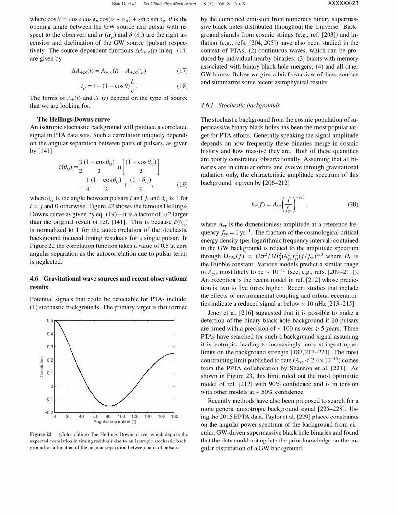
Blair D, et al. Sci China-Phys Mech Astron X (X) Vol. X No. X XXXXXX-23
where cos θ = cos δ cos δp cos(α − αp) + sin δ sin δp, θ is theopening angle between the GW source and pulsar with re-spect to the observer, and α (αp) and δ (δp) are the right as-cension and declination of the GW source (pulsar) respec-tively. The source-dependent functions ∆A+,×(t) in eq. (14)are given by
∆A+,×(t) = A+,×(t) − A+,×(tp) (17)
tp = t − (1 − cos θ)Lc. (18)
The forms of A+(t) and A×(t) depend on the type of sourcethat we are looking for.
The Hellings-Downs curveAn isotropic stochastic background will produce a correlatedsignal in PTA data sets. Such a correlation uniquely dependson the angular separation between pairs of pulsars, as givenby [141]
ζ(θi j) =32
(1 − cos θi j)2
ln[(1 − cos θi j)
2
]−
14
(1 − cos θi j)2
+(1 + δi j)
2, (19)
where θi j is the angle between pulsars i and j, and δi j is 1 fori = j and 0 otherwise. Figure 22 shows the famous Hellings-Downs curve as given by eq. (19)—it is a factor of 3/2 largerthan the original result of ref. [141]. This is because ζ(θi j)is normalized to 1 for the autocorrelation of the stochasticbackground induced timing residuals for a single pulsar. InFigure 22 the correlation function takes a value of 0.5 at zeroangular separation as the autocorrelation due to pulsar termsis neglected.
4.6 Gravitational wave sources and recent observationalresults
Potential signals that could be detectable for PTAs include:(1) stochastic backgrounds. The primary target is that formed
0 20 40 60 80 100 120 140 160 180−0.2
−0.1
0
0.1
0.2
0.3
0.4
0.5
Angular separation (°)
Cor
rela
tion
Figure 22 (Color online) The Hellings-Downs curve, which depicts theexpected correlation in timing residuals due to an isotropic stochastic back-ground, as a function of the angular separation between pairs of pulsars.
by the combined emission from numerous binary supermas-sive black holes distributed throughout the Universe. Back-ground signals from cosmic strings (e.g., ref. [203]) and in-flation (e.g., refs. [204, 205]) have also been studied in thecontext of PTAs; (2) continuous waves, which can be pro-duced by individual nearby binaries; (3) bursts with memoryassociated with binary black hole mergers; (4) and all otherGW bursts. Below we give a brief overview of these sourcesand summarize some recent astrophysical results.
4.6.1 Stochastic backgrounds
The stochastic background from the cosmic population of su-permassive binary black holes has been the most popular tar-get for PTA efforts. Generally speaking the signal amplitudedepends on how frequently these binaries merge in cosmichistory and how massive they are. Both of these quantitiesare poorly constrained observationally. Assuming that all bi-naries are in circular orbits and evolve through gravitationalradiation only, the characteristic amplitude spectrum of thisbackground is given by [206–212]
hc( f ) = Ayr
(ffyr
)−2/3
, (20)
where Ayr is the dimensionless amplitude at a reference fre-quency fyr = 1 yr−1. The fraction of the cosmological criticalenergy density (per logarithmic frequency interval) containedin the GW background is related to the amplitude spectrumthrough ΩGW( f ) = (2π2/3H2
0)A2yr f 2
yr( f / fyr)2/3 where H0 isthe Hubble constant. Various models predict a similar rangeof Ayr, most likely to be ∼ 10−15 (see, e.g., refs. [209–211]).An exception is the recent model in ref. [212] whose predic-tion is two to five times higher. Recent studies that includethe effects of environmental coupling and orbital eccentrici-ties indicate a reduced signal at below ∼ 10 nHz [213–215].
Jenet et al. [216] suggested that it is possible to make adetection of the binary black hole background if 20 pulsarsare timed with a precision of ∼ 100 ns over & 5 years. ThreePTAs have searched for such a background signal assumingit is isotropic, leading to increasingly more stringent upperlimits on the background strength [187, 217–221]. The mostconstraining limit published to date (Ayr < 2.4×10⁻¹⁵) comesfrom the PPTA collaboration by Shannon et al. [221]. Asshown in Figure 23, this limit ruled out the most optimisticmodel of ref. [212] with 90% confidence and is in tensionwith other models at ∼ 50% confidence.
Recently methods have also been proposed to search for amore general anisotropic background signal [225–228]. Us-ing the 2015 EPTA data, Taylor et al. [229] placed constraintson the angular power spectrum of the background from cir-cular, GW-driven supermassive black hole binaries and foundthat the data could not update the prior knowledge on the an-gular distribution of a GW background.

Blair D, et al. Sci China-Phys Mech Astron X (X) Vol. X No. X XXXXXX-24
3
2
1
0-11 -10 -9 -8 -7
0
0.5
1
Figure 23 (Color online) Upper limits on the fractional energy densityof the GW background ΩGW( f ), at a frequency of 2.8 nHz, as comparedagainst various models of the supermassive binary black hole background.The red (grey) solid and dashed lines show the probabilities Pr(ΩGW) thata GW background with energy density ΩGW( f ) exists given the PPTA data,assuming Gaussian and non-Gaussian statistics respectively. Three verticallines mark the 95% confidence upper limits published by NANOGrav [187],EPTA [219] and PPTA [221], where the times next to these lines correspondapproximately to the observing spans of the data sets. The shaded regionis ruled out with 95% confidence by the PPTA data. Gaussian curves rep-resent the probability density functions ρM(ΩGW) given different models: amerger-driven model for growth of massive black holes in galaxies [212],a synthesis of empirical models [210], semi-analytic models (SMBH model1; [221]) based on the Millenium dark matter simulations [222, 223] and adistinct model for black hole growth (SMBH model 2; [224]). Figure takenfrom ref. [221].
4.6.2 Continuous waves
Individual supermassive binary black holes, especially themost nearby and/or massive ones, could provide good oppor-tunities for detection of continuous waves. Unlike compactbinaries in the audio band, supermassive binary black holesdetectable for PTAs are mostly in the early stage of inspiraland therefore emit quasi-monochromatic waves. For an in-spiralling circular binary of component masses m1 and m2,the GW strain amplitude is given by [230]
h0 = 2(GMc)5/3
c4
(π f )2/3
dL, (21)
where dL is the luminosity distance of the source, and Mc isthe chirp mass defined as Mc = Mη5/3, with M = m1 + m2
the total mass and η = m1m2/M2 the symmetric mass ratio.After averaging over the antenna pattern functions given byeqs. (15) and (16) and the binary orbital inclination angle,the Earth-term timing residuals induced by a circular binaryis ∼ h0/2π f .
Before the establishment of major PTAs, Jenet et al. [199]developed a framework in which pulsar timing observationscan be used to constrain properties of supermassive binaryblack holes and applied the method to effectively rule out the
claimed binary black hole system in 3C 66B [231]. In re-cent years growing efforts have gone into investigating thedetection prospects [232–236] of, and designing data analy-sis methods [237–243] for, continuous waves.
Yardley et al. [244] calculated the first sensitivity curveof a PTA to this type of sources using an earlier PPTA dataset presented in ref. [245]. Recently both PPTA [242] andNANOGrav [246] conducted searches for continuous wavesin their corresponding real data sets. Because of its excellentdata quality, PPTA has achieved by far the best sensitivity forcontinuous waves. Figure 24 shows a sky map of PPTA’s sen-sitivities to circular binary black holes of chirp mass 109 Mand orbital period of ∼6 years [242]. Unfortunately mostnearby galaxy clusters or binary black hole candidates arewithin the less sensitive sky region. Zhu et al. [242] also pre-sented the most stringent upper limit (published to date) onthe GW strain amplitude (h0 < 1.7 × 10⁻¹⁴ at 10 nHz) andon the local merger rate density of supermassive binary blackholes (fewer than 4 × 10⁻³ Mpc−3 Gyr−1 for Mc > 1010 M).
4.6.3 Gravitational wave memory
A GW memory is a permanent distortion in the spacetimemetric [247,248]. Such effects can be produced during merg-ers of supermassive binary black holes and cause instanta-neous jumps of pulse frequency. For a single pulsar, thisis indistinguishable from a glitch event. With a timing ar-ray, GW memory effects can be searched for as simultaneouspulse frequency jumps in all pulsars when the burst reachesthe Earth. It has been suggested that GW memory signalsare in principle detectable with current PTAs for black holemass of 108 M within a redshift of 0.1 [249–252]. However,the event rate is highly uncertain. Current estimates are verypessimistic, predicting only 0.03 to 0.2 detectable events ev-ery 10 years for future PTA observations based on the SKA
Figure 24 (Color online) Sky distribution of luminosity distance (in Mpc)out to which a circular binary black hole of chirp mass 109 M and orbital pe-riod of 5 nHz could be detected with the PPTA data set. Sky locations of the20 PPTA pulsars are indicated by “?”. White diamonds mark the location ofpossible supermassive black hole binary candidates or nearby clusters: Virgo(16.5 Mpc), Fornax (19 Mpc), Norma (67.8 Mpc), Perseus (73.6 Mpc), 3C66B (92 Mpc), Coma (102 Mpc) and OJ287 (1.07 Gpc). Figure originallypublished in ref. [242].

Blair D, et al. Sci China-Phys Mech Astron X (X) Vol. X No. X XXXXXX-25
[235, 253]. Actual searches in existing PTA data sets—seeref. [254] for PPTA and ref. [255] for NANOGrav—have setupper limits on the memory event rate, which remain ordersof magnitude above theoretical expectations.
4.6.4 Gravitational wave bursts
Potential burst sources of interest to PTAs include the forma-tion or coalescence of supermassive black holes, the periapsispassage of compact objects in highly elliptic or unbound or-bits around a supermassive black hole [256], cosmic (super)string cusps and kinks [257–259], and triplets of supermas-sive black holes [260]. Finn & Lommen [256] developed aBayesian framework for detecting and characterizing burstGWs (see also ref. [261]). Zhu et al. [243] recently proposeda general coherent (frequentist) method that can be used tosearch for GW bursts with PTAs. No specific predictionshave been made for detecting GW bursts with PTAs in theliterature. There has been no published results on searchesfor bursts using real PTA data.
4.7 Summary and future prospects
With their existence predicted by general relativity one cen-tury ago, GWs have not yet been directly detected. However,it is widely believed that we are on the threshold of openingthe gravitational window into the Universe. In the audio band(from 10 to several kilo Hz), 2nd-generation laser interferom-eters such as Advanced LIGO are about to start scientific ob-servations and a detection of signals from compact binary co-alescences (e.g., binary neutron star inspirals) is likely withina few years (see Sect. 2). In the nanohertz frequency range,PTA experiments have achieved unprecedented sensitivitiesand started to put serious constraints on the cosmic popula-tion of supermassive black hole binaries.
The sensitivity of a PTA can be improved by a) increas-ing the data span and observing cadence, b) including morepulsars in the array, and c) reducing the noise present in thedata. Regarding the first two factors, the combination of datasets from three PTAs to a single IPTA data set offers themost straightforward benefit. Other ongoing efforts includeoptimization of observing strategies, searches for millisec-ond pulsars, characterization of various noise processes andcorresponding mitigation methods, and development of ad-vanced instrumentations. In the longer term, pulsar timingobservations with FAST and SKA will provide advances inall aspects of PTA science, not only leading to the detectionof GWs but also allowing detailed studies of the nanohertzgravitational Universe.
5 Searching for gravitational waves in theCMB
We briefly review the efforts for the detection of cosmolog-ical GWs into the CMB anisotropies of the early Universe.
We describe the progresses over the last year, the current up-per limit to tensor modes in cosmology coming from their di-rect search into CMB polarization, and the expectations fromnear and long term probes.
5.1 Introduction
The ΛCDM cosmological concordance model, now sup-ported by all observations including the latest Planck mea-surements of the CMB (see ref. [262] and references therein),is composed by a non-relativistic (Cold) Dark Matter compo-nent (26%), known particles (baryons and leptons, 4%), aswell as a Cosmological Constant responsible for about 70%of the entire cosmic energy density. In the early phases ofexpansion, the ΛCDM model assumes an era of acceleratedexpansion, known as inflation, in which an almost scale in-variant spectrum of Gaussian density perturbations is gener-ated, responsible for the structures we observe today. Manyopen problems concerning this model are related to the exactnature of the dark cosmological components, as well as to thedetails of the very early Universes, in order to discriminatebetween different inflationary scenarios. The latter aspect isthe subject of the present contribution to the Next GenerationGravitational Wave Antenna conference which took place atthe Kavli Institute in Beijing, in May 2015.
According to the inflationary process, if the latter is earlyenough, a production of cosmological GWs would take placealong with the density ones. A key parameter for describingthem is the tensor to scalar ratio, i.e. the ratio between theamplitude in tensor (GWs) power and scalar (density) ones:
r =AT
AS. (22)
Cosmological GWs do excite one mode of linear polariza-tion in the CMB. The latter is characterized by anisotropiesin the temperature (T ), gradient modes of the linear polariza-tion tensor (E) and curl component, the B-modes, which iswhere the cosmological GWs imprint their contribution. Theduration of the the decoupling process of photons, the ori-gin of the CMB, determines the angular scale at which theB-modes from GWs should be detected, which is about 1 inthe sky. On the other hand, at the arcminute scale, the darkmatter traced by luminous objects would gravitationally lensthe CMB photons, causing a transfer of power from the Eto B modes. The latter effect is most relevant for investigat-ing the dark cosmological components, in particular in cross-correlation with LSS surveys [263]. An intensive experimen-tal effort is ongoing in the attempt to detect the B-modes onall angular scale, which is the subject of this contribution. Insect. 5.2 we describe the main phenomenology determiningthe angular power spectrum of CMB anisotropies. In sect.5.3 we describe the status of B-mode observations at the timeof the conference. Finally, in sect. 5.4, we describe the ex-pectations in the near, intermediate and far term.

Blair D, et al. Sci China-Phys Mech Astron X (X) Vol. X No. X XXXXXX-26
5.2 CMB anisotropies
We describe here the main phenomenology of the CMB T , Eand B-modes in terms of their angular power spectra. In Fig-ure 25 we show the power spectra of a typical ΛCDM model,corresponding to the Planck best fit in terms of the main cos-mological parameters, and differing for the value of r, whichis set equal to 0.1. Effects at decoupling are marked in red,while blue labels mean secondary anisotropies, i.e. those im-printed on the line of sight to us. The horizon scale at de-coupling, marking the distinction between super-horizon andsub-horizon perturbations at the corresponding epoch, corre-sponds to about l = 200, which is about 1 degree in the sky.The T modes feature basically unperturbed primordial poweron larger scales, while being subject to oscillations on smallerones, characterized by competition between radiation pres-sure and gravitational potentials provided by the dark matter.Since polarization is sourced by the local quadrupole at de-coupling, the acoustic oscillations are transferred to E modes,as well as their correlation with T , named T E components.The B-modes feature a peak at l ' 100 due to cosmologicalGWs, as well as the leak of power from E to B due to grav-itational lensing, causing a peak, resembling the E acousticoscillations, centered at about l = 1000. On large scales, sec-ondary effects coming from the Integrated Sachs-Wolfe andreionization, which we do not treat here, are also highlighted.
5.3 B-mode observations
An extraordinary progress has occurred in the year 2014. Po-larBear has published the first detection of auto-spectra of B-modes at the arcminute scale. That was found consistent withpredictions from cosmological gravitational lensing withinthe ΛCDM concordance model [264], and, to date, it rep-resents the first detection of cosmological B-modes from onesingle experiment, at the auto-spectrum level. Immediatelyafter, an excess on the degree angular scales, which couldbe ascribed to cosmological GWs, was announced by the BI-CEP2 collaboration [265]. The Planck collaboration, by ana-lyzing the data of the polarization sensitive at 353 GHz, wasable to estimate the level of Galactic contamination from ther-mal dust to the BICEP2 measurements, finding that, withinuncertainties, the latter are to be attributed to the foregroundemission [266]. The BICEP2 and Planck collaborations pro-duced a join analysis in the sky region which was observedby BICEP2, using also the data from the Keck array, resultingin an upper limit on the value of r coming for the first timefrom direct B-mode measurements [267]:
r 6 0.12 (95% confidence level). (23)
Recently B-mode measurements by the ACTpol [268] andSPTpol [269] observatories have been reported. In Figure 26we show the measurements on B-modes at the beginning of2014 and at the time of the Conference. The upper limitsturned into actual measurements, extending from the degreeangular scales by the BICEP-Keck-Planck data (labeled by
Figure 25 (Color online) CMB power spectra for ΛCDM cosmologies,with a contribution from cosmological gravitatioanl waves corresponding tor = 0.1, along with the main effects in their relevant angular domain. TheBlack line represent the T component. The E is blue, while the T E correla-tion is magenta. The B-modes are in dark red.
Figure 26 (Color online) Experimental data at the beginning of 2014 (left)and now (right). Courtesy of Yujii Chinone of the University of CaliforniaBerkeley.
BKP) to the PolarBear ones at the arcminute scale. Also plot-ted, the theoretical curves for ΛCDM models with variouslevels of r, as shown.

Blair D, et al. Sci China-Phys Mech Astron X (X) Vol. X No. X XXXXXX-27
5.4 Expectations in the near, intermediate and long term
At this moment, operating probes are mounting new de-tectors to go multi-frequency, in order to be able to mon-itor and subtract the Galactic foregrounds. We quote herea fraction of the most important efforts, a complete listbeing available at lambda.gsfc.nasa.gov/product/expt. ThePolarBear program will turn into the PolarBear-2 programtaking data at 90, 150 and 220 GHz in 2016, while twoother telescopes will be built, constituing the Simons Array(bolo.berkeley.edu/polarbear). The same frequency range isbeing probed by the BICEP and Keck (bicepkeck.org) ar-rays, as well as the ACTpol (www.princeton.edu/act) andSPTpol (pole.uchicago.edu) telescopes. Ground measure-ments, as the quoted ones, are likely to process, in thenear term, from now to a few years, the frequency in-terval extending from 90 to 220 GHz. The limit at lowfrequency comes from the relevance of the polarized syn-chrotron Galactic foreground, which is at this moment onlyknown on large angular scales thank to the Planck [270]and WMAP [271] observations. At high frequency, the at-mosphere is not negligible for these measurements. Onthe other hand, it is necessary to monitor lower and higherfrequencies, where the synchrotron and the dust representvery relevant diffuse Galactic foregrounds, respectively. Atlow frequency, and in the intermediate term, the CLASS(sites.krieger.jhu.edu/class) will be extending observations onlarge portion of the sky down to 40 GHz. A similar programwill be the LSPE balloon (planck.roma1.infn.it/lspe); bothprobes also observe below 300 GHz on the high frequencyside. At higher frequencies baloon programmes from SPI-DER (cmb.phys.cwru.edu/ruhl−lab/spider.html) and EBEX(groups.physics.umn.edu/cosmology/ebex) have observed upto 410 GHz, and are currently analyzing the data. Ambitiousprograms from satellites, with frequency ranges probing thehigh and low frequency tails, exist. In the intermediate term, asatellite dedicated to the large angular scales will be LiteBird(litebird.jp/eng). In the long term, many frequency bands willbe observed by the PIXIE (asd.gsfc.nasa.gov/pixie) satellite,with the goal of determining with great accuracy the highfrequency foreground properties in terms of large scale dis-tribution, composition and frequency scaling. Also in thelong term, the idea of a nearly ultimate satellite, CORE+
(www.core-mission.org), with the goal of mapping the B-modes on the whole sky down to the arcminute scale, arebeing proposed. Within these efforts, the ultimate thresholdof detection for r is claimed of order 10−3.
6 Roadmap for gravitational wave detection inspace—a preliminary study
6.1 Introduction
In 2008, under the auspices of the National Microgravity lab-oratory of the Institute of Mechanics, Chinese Academy ofSciences (CAS), an (unofficial) gravitational physics consor-
tium comprising a number of institutes and universities bothwithin and outside the CAS was established. The primaryobjective of the consortium is to coordinate and promote re-search in the detection of GW in space in China. A roadmapwas soon worked out in order to build up the expertise andrequired technologies step by step for future prospective Chi-nese mission. As a first step of the roadmap, a geodesy mis-sion to monitor the temporal variation of the Earth gravityfield using low-low satellite to satellite tracking by meansof laser interferometry will be developed. This will enableus to acquire the key technologies at a lower level of preci-sion and at the same time assemble a core team for furtherdevelopment. As a geodesy mission will only test laser in-terferometry in space and is less stringent in requirement ininertial sensor related technologies, a LISA Pathfinder (LPF)type mission is also required at some stage to test the iner-tial sensor and the related dragfree technologies to the levelof precision required by GW detection. As the two proofmasses in an LPF type mission may be regarded naturally asa one dimensional gravity gradiometer, in recent years, somework has also been ongoing to explore possible additionalscientific benefits of an LPF type mission, apart from testingthe key technologies in space.
Supported by the Xiandao (pioneer explorer) program ofthe National Space Science Center of the CAS, the generalrelativity group of the Morningside Center of Mathematicsand Institute of Applied Maths, CAS have been undertakingthe task of doing preliminary study on the prospective mis-sions outlined in the roadmap. The purpose of the presentarticle is to present an overview of the work we have beendoing in this area.
The outline of the present article is described as follows. Insect. 6.2, we will outline a feasible design and its primary sci-ence driver for a mission to detect GWs in space. This is thenfollowed in sect. 6.3 by a sketch of a geodesy mission studywe have been doing. In sect. 6.4, we will discuss the preci-sion measurement of the Earth’s gravitomagnetic field as pos-sible additional science for a LISA Pathfinder type mission.Some brief remarks will be made in sect. 6.5 to conclude thissection.
6.2 Gravitational wave detection in space
Concurrent to the mission study in satellite gravity beginningin 2009 which will be described in sect. 6.3, a preliminarystudy was also made on the scientific potential of a space-borne gravitational detector whose most sensitivity frequencyband centers around 0.01 or 0.1 Hz. The main theme ofthe study was to look at possible GW sources around 0.01Hz which was not entirely well understood at then. WithALIA [272,273] adopted as a representative mission conceptaround the 0.01 Hz band, further analysis revealed that thereis a rich source of intermediate mass black hole binaries athigh redshift and the detection would shed light on the blackhole-galaxy coevolution during the structural formation pro-

Blair D, et al. Sci China-Phys Mech Astron X (X) Vol. X No. X XXXXXX-28
cess of the Universe [274].During 2011–2013, a subsequent, more indepth study was
made [275, 276]. This time technological constraints weretaken into account and we strived to obtain a balance be-tween merits in science and viability in technologies. Withthis guideline in mind, after examining a few representativemission options, a mission concept with the following base-line design parameters (Table 5) and sensitivity (Figure 27)is favoured as a blueprint for more in depth study in the nearfuture.
The capability of the mission designs to detect lighter seedblack holes at high redshifts is illustrated in Figure 28 [275].
A semi-analytic Monte Carlo simulation was also carriedout to understand the cosmic black hole merger historiesstarting from intermediate mass black holes at high redshiftas well as the possible scientific merits of the mission designin probing the light seed black holes and their coevolutionwith galaxies in early Universe (Figure 29) [275].
Moreover, the mission design is also capable of probingIMRI (intermediate mass ratio inspiral) in dense star clustersin the local Universe. Presented in Table 6 is some eventrate calculations for IMRIs in local Universe [275]. It shouldbe remarked that estimate is model dependent and subject tomany uncertainties and we should not attach too much im-portance to the precise numbers. Instead, it illustrates theadvantage of shifting slightly the most sensitive region of themeasurement band to a few hundredth Hz. As far as IMRIsare concerned, the event rate goes up as the cubic of the im-provement in sensitivity.
The result of the study suggests that, by choosing the arm-length of the interferometer to be three million kilometersand shifting the sensitivity floor to around one-hundredth Hz,
Table 5 Baseline design parameters
L (m) D (M) P (W) S posi
(pm√
Hz
)S acc
(m s−2√
Hz
)3 × 10⁹ 0.45–0.6 2 5–8 3 × 10⁻¹⁵ (> 0.1 mHz)
10−4 10−3 10−2 10−1 100 101 10210−22
10−21
10−20
10−19
10−18
10−17
10−16
FrequencyI(Hz)
Str
ainI
sens
itivi
tyI(
perI
root
IHz)
eLISA
LISA 8IpmI(D=0.45m)
5IpmI(D=0.6m)
Figure 27 (Color online) Sensitivity curves of the mission designs, takeninto consideration the confusion noise generated by both galactic and extra-galactic compact binaries converted from those by Bender and Hils [277]and Farmer and Phinney [278].
0 2000 4000 6000 8000 100000
5
10
15
20
Total massin M .
Red
shiftz
LISAALIA
5 pm(D=0.6 m)
8 pm(D=0.45 m)
Figure 28 (Color online) All-angle averaged detection range under a sin-gle Michelson threshold SNR of 7 for 1:4 mass ratio IMBH-IMBH binaries,one year observation prior to merger. For each mission option, both upperand lower confusion noise levels (represented by the dashed curve and dotteddashed curve respectively) due to extragalactic compact binaries are consid-ered.
Figure 29 (Color online) Event rates given by the area enclosed by thecurves.
Table 6 Expected globular cluster harbored IMBH-BH final inspi-rals and mergers detectable for year-long observation, scaled in unit offtot0.1
ν010−10 yr−1
10 Mµ
Mission option Upper level of confusion Lower level of confusion
5 pm (D = 0.6 m) ∼ 90 ∼ 130
8 pm (D = 0.45 m) ∼ 26 ∼ 32
together with a very moderate improvement on the positionnoise budget, there are certain mission options capable of ex-ploring light seed, intermediate mass black hole binaries athigh redshift that are not readily accessible to eLISA/LISA[279, 280], and yet the technological requirements seem towithin reach in the next few decades for China [275, 276].
6.3 Low-low satellite to satellite tracking using laser in-terferometry
In 2009, commissioned by the National Space Science Cen-ter, Chinese Academy of Sciences, a comprehensive studywas undertaken in order to understand various aspects of afuture low-low satellite to satellite tracking mission with mi-crowave ranging replaced by laser interferometry.
During the feasibility study, different groups undertakingdifferent tasks within the mission study suggested possible

Blair D, et al. Sci China-Phys Mech Astron X (X) Vol. X No. X XXXXXX-29
mission designs for future satellite gravity missions. Dueto the limitation imposed by aliasing generated by the atmo-sphere and ocean currents, perhaps in a way not too surpris-ing, subject to minor variations, all groups came up with verysimilar mission design (see for instance ref. [281], comparealso with that of the NGGM mission [282,283] whose missondesign parameters are given in Table 7.
The critical difference between the two mission designsis the attitude of the orbit. For Option 1 in Table 7, thruster(dragfree) technology is required to maintain the orbit at sucha low attitude.
By means of the semi-analytic method [284], the capabil-ity of static gravity field recovery of the mission designs isillustrated in Figures 30 and 31.
For the capability to track temporal variation of the Earthgravity field, using the GLDAS model and taking into ac-count of AOD aliasing, the hydrological signal recovery isdisplayed in Figures 32–34 for the two mission design con-sidered.
Work is still ongoing to understand the various aspects ofthe mission concepts (see for instance refs. [285, 286]).
6.4 Precision measurement of gravitomagnetic field interms of gradiometry
Apart from detection of GWs, another out-standing problem
Table 7 Baseline design parameters for two representative mission options
Mission Accelero- Laser Satellite Inter
duration Orbit meter (mHz (mHz altitude satellite
to 3 Hz) to 3 Hz) range
1 10-year Polar 10−10 10–30 300 km 50−
ms−2 Hz−1/2 nm Hz−1/2 200 km
2 10-year Polar 10−9 10–30 420− 50−
ms−2 Hz−1/2 nm Hz−1/2 450 km 200 km
0 50 100 150 200 250 30010−15
10−10
10−5degree variance
degree
degr
ee R
MS
KaulaGRACEGOCEAlti tude: 420 kmAlti tude: 300 km
Figure 30 (Color online) Static gravity field recovery in terms of spheri-cal harmonic degree variance for different altitudes. Range: 100 km, lasermetrology: 10 nm/
√Hz.
0 50 100 150 200 250 30010−15
10−10
10−5degree variance
degree
degr
ee R
MS
GRACEGOCELaser 50 nm/√HzLaser 30 nm/√HzLaser 10 nm/√Hz
Figure 31 (Color online) Static gravity field recovery in terms of spheri-cal harmonic degree variance for different laser accuracy. Altitude: 300 km,range: 100 km.
Figure 32 (Color online) GLDAS model in terms of gravity anomaly (unitsin µgal) for October, 2009, up to harmonic degree 90.
Figure 33 (Color online) Recovered GLDAS anomaly for October, 2009,up to harmonic degree 90. Altitude at 300 km with 400 km Gaussian filter.
Figure 34 (Color online) Recovered GLDAS anomaly for October, 2009,up to harmonic degree 90. Altitude at 450 km with 400 km Gaussian filter.

Blair D, et al. Sci China-Phys Mech Astron X (X) Vol. X No. X XXXXXX-30
in experimental relativity is the detection of gravitomagneticfield [287, 288] of a rotating body which may be regarded asa test of general relativity at the planetary scale. As the GMfield is part of the spacetime curvature, it will contribute to thetidal forces acting on a family of nearby free falling particles.It is natural to contemplate to detect its presence through themeasurement of the tidal force gradient generated by the GMfield [289, 290]. As the two free falling test masses (TMs) inthe LISA Pathfinder type mission naturally constitute a onedimensional gravity gradiometer, apart from testing the tech-nologies for GW detection, we also try to look at whethersuch mission is also capable of measuring GM field around aplanet.
Consider an ideal case in which the Earth is modelled as auniform rotating spherical body. Let (t, xi), i = 1, 2, 3 be theEarth centered coordinates and e(a), a = 1, 2, 3 be the Earthpointing orthonormal three frame attached to the center ofmass of the spacecraft. Units in which c = G = 1 will beadopted.
Given an Earth pointing, drag-free spacecraft orbiting theEarth in a nearly circular orbit (radius a ≈ 1000 km) withconstant inclination i. Two TMs are housed in the along trackdirection separated by a distance d ≈ 50 cm (see Figure 35).Let δi be the relative displacement of the two TMs. In a timescale short compared with the Lense-Thirring precession ofthe orbital plane and subject to δi d, at the 1 PN level, thegeodesic deviation (Jacobi) equation describing the relativedisplacement δi may be simplified to become (see ref. [291]for details)
δ1(t) = −2ωδ2(t) +6Jωd cos i
a3 ,
δ2(t) = 2ωδ1(t) + 3ω2δ2(t) −9dJtω2 cos i
a3 , (24)
δ3(t) = −ω2δ3(t) +3dJω sin i cos(ωt)
a3 .
At the Newtonian level, we recover the well known ClohessyWiltshire [292] (Hill) equation from eq. (24).
In the direction transverse to the orbit plane, at the New-tonian level, it is known that the relative motion of the two
Figure 35 (Color online) Two TMs are housed in the along track direc-tion following a nearly circular orbit. The spacecraft may be viewed as agyroscope rolling about the transverse direction e(3).
TMs resembles that of a simple harmonic oscillator (see Fig-ure 36). The presence of a gravitomagnetic field serves togenerate a Lorentz type force acting on the TMs and results ina forced harmonic motion. Up to a constant, the frequency of
the force matches the frequency ω =
√Ma3 determined by the
central gravitational potential and this gives rise to a resonantforced harmonic oscillation. Further numerical simulationsindicate that the resonant oscillation prevails for more generalelliptic orbits and with Earth gravity field multiples taken intoaccount. The amplitude of the oscillation will not grow un-bounded when nonlinearity of the Lense-Thirring precessionof the orbit plane takes effect, but this will occur in a timescale much longer than the mission lifetime of around oneyear. By integrating the PN generalization of the CW equa-tions in eq. (24), we further find that the growing oscillationamplitude of the TMs in the transversal direction is given by(see Figure 37)
sGM(t) =3GdJ sin i sin(ωt)
2c2a3 t. (25)
For our orbit choice, the signal has frequency about 0.1 mHzand its magnitude will reach a few nanometers within 1–2 d.
To understand the physical picture underlying the signalreadout given in eq. (25), we note that gravitomagnetic field,apart from generating a Lense-Thirring precession of the or-bital plane, also generates a precession of the orthonormalframe e(a) [293]. In particular, the results in the precessionof the plane perpendicular to e(3) that contains the TMs. Asa result, the relative displacement of the two TMs is actu-ally generated by the differential precession between the or-bital plane and the plane perpendicular to e(3) (see Figure 38).If we regard e(a) as a gyroscope resembling that in the GPB
Figure 36 (Color online) For a circular orbit, take one TM as reference,the motion of the second TM in the transverse direction is equivalent to thatof a forced harmonic oscillator with natural frequency which matches that ofthe orbital frequency.

Blair D, et al. Sci China-Phys Mech Astron X (X) Vol. X No. X XXXXXX-31
Figure 37 (Color online) The illustration of the GM signal.
Figure 38 (Color online) Due to the differential precession between thespacecraft (or the local frame) and the orbital plane, the two TMs will oscil-late relative to the spacecraft along the transverse direction.
experiment [294] and the orbit itself is also a gigantic gyro-scope, then we may see that a very distinctive feature of theproposed measurement scheme is that, unlike GPB or LA-GEOS/LARES [295–297] which measures precession withrespect to an globally defined inertial reference, it measuresthe differential precession of the two gyroscopes.
With the theoretical foundation of the measurementscheme worked out above, there remain many key issues tobe resolved or understood in order to implement the mea-surement scheme in a physically realistic situation (see forinstance ref. [298]). The study is still ongoing and we hopeto report further progress in the near future.
6.5 Concluding remarks
An overview is given on the work we have been doing in thepast few years in relation to detection of GW in space. Need-less to say there is no end to such study. It is envisaged thatmore in depth study will be undertaken in the next few yearsto contribute to the development of GW detection in China.
7 Space missions for gravitational wave detec-tion
7.1 Introduction
For detection of GWs in the low frequency (100 nHz–0.1 Hz)band and in the middle frequency band (0.1 Hz–10 Hz), spaceinterferometric detectors are needed. GW sources in thesebands are abundant. For the critical technologies requiredto detect GWs in the range of 0.1 mHz to 1 Hz, the Euro-pean Space Agency (ESA), at the time of writing, is in the fi-nal stage of preparing LISA Pathfinder (Laser-InterferometricSpace Antenna Pathfinder) for launch. The mission willdemonstrate critical technologies for future GW observato-ries, in a space environment. These technologies include:inertial sensing, drag-free attitude control, and interferome-try with free-falling mirrors. LISA Pathfinder is scheduled tolaunch at the end of this year. The success of LISA Pathfinderwill prepare the technological basis for space laser interfer-ometers both in Earth orbit and in solar orbit.
On 28 November 2013, ESA announced its new vision tostudy the invisible universe. The hot and energetic Universeand the search for GWs will be the focus of ESA′s next twolarge science missions L2 and L3—the “Hot and EnergeticUniverse” for L2 and “The Gravitational Universe” for L34) .
The ESA L3 mission is likely to have a launch oppor-tunity in 20344). It is expected that eLISA/NGO (evolvedLISA/New Gravitational-Wave Observatory) GW mission orits further evolved version will be the major candidate. Sinceit will take one year to transfer to the science orbit, a startingtime for the science phase is likely to be in 2035.
Motivated by the multiplicity of astrophysical GW sourcesfor eLISA/NGO mission and other solar-orbit GW missions,and because of the 20 year period to 2035, there is cur-rently a renaissance of Earth-orbiting GW mission propos-als. Sufficiently numerous sources exist to justify an Earth-orbiting GW mission indicating that these mission proposalsare worth considering before eLISA begins. Such a missionwould be a natural precursor to a solar-orbit mission.
An essential technology for achieving sufficient GW sensi-tivity of space laser interferometers is Time Delay Interferom-etry. Time delay interferometry (TDI) is needed to suppresslaser frequency noise. In the next subsection, we review anddiscuss TDI.
7.2 Time delay interferometry
In space-based laser-interferometric GW antennas, the armlengths vary according to the orbital dynamics of the inde-pendent spacecraft. In order to attain the requisite sensi-tivity, laser frequency noise must be suppressed below thesecondary noises such as the optical path noise, accelera-tion noise etc. For suppressing laser frequency noise in thisenvironment, it is necessary to use time delay interferome-
4) http://www.esa.int/Our Activities/Space Science/ESA s new vision to study the invisible Universe

Blair D, et al. Sci China-Phys Mech Astron X (X) Vol. X No. X XXXXXX-32
try (TDI) in the analysis to match the optical path length ofdifferent beams closely. The better the match of the opticalpath lengths, the better the cancellation of the laser frequencynoise and the easier it is to achieve the requisite sensitivity.In case of exact match, the laser frequency noise is fully can-celled, as in the original Michelson interferometer.
The TDI concept was first used in the study of ASTROD(Astrodynamical Space Test of Relativity using Optical De-vices) mission concept [299–301]. In deep-space interfer-ometry, long distances are invariably involved. Due to longdistances, laser light is attenuated to a great extent at the re-ceiving spacecraft. To transfer the laser light back or to an-other spacecraft, amplification is needed. The procedure isto phase lock the local laser to the incoming weak laser lightand to transmit the local laser light back to another spacecraft.Liao et al. [302,303] have demonstrated the phase locking ofa local oscillator with 2-pW laser light in laboratory. Dick etal. [304] have demonstrated phase locking to 40-fW incom-ing weak laser light. The power requirement feasibility forboth e-LISA/NGO and ASTROD-GW (ASTROD optimizedfor Gravitational Wave [GW] detection) is met with these de-velopments. In the 1990s, Ni et al. [299, 300] used the fol-lowing two TDI configurations during the study of ASTRODinterferometry and obtained numerically the path length dif-ferences using Newtonian dynamics.
These two TDI configurations are the unequal arm Michel-son TDI configuration and the Sagnac TDI configuration for3 spacecraft formation flight. The principle is to have twosplit laser beams to go to Path 1 and Path 2 and interfere attheir end path. For unequal arm Michelson TDI configura-tion, one laser beams starts from spacecraft 1 (S/C1) directedto and received by spacecraft 2, and optical phase lockingthe local laser in spacecraft 2 (S/C2); the phased locked laserbeam is then directed to and received by spacecraft 1, and op-tical phase locking another local laser in spacecraft 1; and soon following Path 1 to return to (S/C1):
Path 1: S/C1→S/C2→S/C1→S/C3→S/C1.The second laser beam starts from S/C1 also, but follows theroute:
Path 2: S/C1→S/C3→S/C1→S/C2→S/C1,to return to S/C1 and to interfere coherently with the firstbeam. If the two paths has exactly the same optical pathlength, the laser frequency noises cancel out; if the opticalpath length difference of the two paths are small, the laserfrequency noises cancel to a large extent. In the Sagnac TDIconfiguration, the two paths are:
Path 1: S/C1→S/C2→S/C3→S/C1,Path 2: S/C1→S/C3→S/C2→S/C1.Since then we have worked out the same things nu-
merically for LISA [305], eLISA/NGO [306], NGO-LISA-type with 2 × 10⁶ km arm length [306], ASTROD-GW with no inclination [307, 308], and ASTROD-GWwith inclination [309]. Schematic orbit configuration ofASTROD-GW mission design [309] and LISA-type missiondesign (http://sci.esa.int/lisa/35596-schematic-of-lisa-orbit/)
are shown in Figures 39 and 40. For the numerical evalua-tion, we take a common receiving time epoch for both beams;the results would be very close to each other numerically ifwe take the same start time epoch and calculate the path dif-ferences. We refer to the path S/C1→S/C2→S/C1 as a(path)and the path S/C1→S/C3→S/C1 as b(path). Hence the dif-ference ∆L between Path 1 and Path 2 for the unequal-armMichelson can be denoted as ab−ba = [a, b]. Here ab meansa path followed by b path. The unequal-arm Michelson isnow commonly called the X-configuration [310, 311]. Theresult of this TDI calculation for ASTROD-GW orbit with1inclination is shown in Figure 41.
Time delay interferometry has been investigated for LISAmuch more thoroughly since 1999 [310, 311]. First-generation and second-generation TDIs have been proposed.In the first generation TDIs, static situations are considered.In the second generation TDIs, motions are compensated toa certain degree. The X-configurations considered above be-longs to the first generation TDI configurations. We shallnot review more about these developments here, but refer thereaders to the excellent review article by Tinto and Dhurand-har [311] for a comprehensive treatment.
We compile for comparison the resulting differences for to
Figure 39 (Color online) Schematic of ASTROD-GW orbit configurationwith inclination.
Figure 40 (Color online) Schematic of LISA-type orbit configuration.

Blair D, et al. Sci China-Phys Mech Astron X (X) Vol. X No. X XXXXXX-33
Table 8 Comparison of the resulting differences for second generation TDIs (n = 1 and n = 2) due to arm length variations for various mission proposals –eLISA/NGO, an NGO-LISA-type mission with a nominal arm length of 2 × 10⁶ km, LISA and ASTROD-GW
TDI path difference ∆L
2*TDI configuration eLISA/NGO [306] NGO-LISA-type with LISA [305] ASTROD-GW
2×10⁶ km arm length [306] (1 inclination) [309]
Duration 1000 d 1000 d 1000 d 10 years
n = 1 [ab, ba] −1.5 to +1.5 ps −11 to +12 ps −70 to +80 ps −228 to +228 ns
3 × n = 2 [a2b2, b2a2] −11 to +12 ps −90 to +100 ps −600 to +650 ps −1813 to +1813 ns
[abab, baba] −6 to +6 ps −45 to +50 ps −300 to +340 ps −907 to +907 ns
[ab2a, ba2b] −0.0032 to +0.0034 ps −0.0036 to +0.004 ps −0.015 to +0.013 ps −0.66 to +0.66 ns
Nominal arm length 1 Gm (1 Mkm) 2 Gm 5 Gm 260 Gm
Requirement on ∆L 10 m (30 ns) 20 m (60 ns) 50 m (150 ns) 500 m (1500 ns)
Table 9 Frequency classification of gravitational waves [314,315]
Frequency band Detection method
Ultra high frequency band: above 1 THz Terahertz resonators, optical resonators, and magnetic conversion detectors
Very high frequency band: 100 kHz–1 THz Microwave resonator/wave guide detectors, laser interferometers and Gaussianbeam detectors
High frequency band (audio band)a): 10 Hz–100 kHz Low-temperature resonators and ground-based laser-interferometric detectors
Middle frequency band: 0.1 Hz–10 Hz Space laser-interferometric detectors of arm length 1000 km–60000 km
Low frequency band (milli-Hz band)b): 100 nHz–0.1 Hz Space laser-interferometric detectors of arm length longer than 60000 km
Very low frequency band (nano-Hz band): 300 pHz–100 nHz Pulsar timing arrays (PTAs)
Ultra low frequency band: 10 fHz–300 pHz Astrometry of quasar proper motions
Extremely low (Hubble) frequency band (cosmological band):1 aHz–10 fHz
Cosmic microwave background experiments
Beyond Hubble-frequency band: below 1 aHz Through the verifications of inflationary/primordial cosmological models
a) The range of audio band (also called LIGO band) normally goes only to 10 kHz
b) The range of the milli-Hz band is 0.1 mHz to 100 mHz
Figure 41 (Color online) Path length differences between two opticalpaths of the Unequal-arm Michelson TDI configuration (X-configuration)for ASTROD-GW orbit formation with 1 inclination.
arm second generation two-arm TDIs with n = 1 and n = 2 (nis the degree of polynominal in ab, ba, a2 and b2) due lengthvariations for various mission proposals – eLISA/NGO, anNGO-LISA-type mission with a nominal arm length of 2 ×10⁶ km, LISA and ASTROD-GW.We note that:
i. All the second-generation TDIs considered for theone-detector case for eLISA/NGO, for NGO-LISA-type with2× 106 km arm length, for LISA and for ASTROD-GW with1 inclination basically satisfy this requirement on ∆L (Ta-ble 8).
ii. The requirement for unequal arm Michelson (X-configuration) TDI of ASTROD-GW needs to be relaxed byabout 2 orders (Figure 41).
iii. In view of the possibility of a GW mission in Earth or-bit, numerical TDI study for GW missions in Earth orbit aredesired.
iv. Experimental demonstration of TDI in laboratory forLISA has been implemented in 2010 [312]. eLISA and theoriginal ASTROD-GW TDI requirement are based on LISArequirement, and hence also demonstrated. With the presentpace of development in laser technology, the laser frequencynoise requirement is expected to be able to compensate for2–3 order of TDI requirement relaxation in 20 years.
v. X-configuration TDI sensitivity for GW sources hasbeen studied extensively for eLISA [280]. It satisfies the

Blair D, et al. Sci China-Phys Mech Astron X (X) Vol. X No. X XXXXXX-34
present technological requirements well. With enhancedlaser technology expected, it would also be good for study-ing the ASTROD-GW and various GW missions in Earth or-bit. The study for GW sensitivity and GW sources for otherfirst-generation and second-generation TDIs would also beencouraged.
7.3 Frequency classification of gravitational waves
In electromagnetism, the frequency spectrum of electromag-netic waves are classified into radio waves, millimeter waves,infrared, optical, ultraviolet, X-ray and γ-ray etc. For GWs,it is also desirable and useful to give a frequency classifica-tion. We extend the common classification of Thorne [313]to reach a complete classification [314] shown in Table 9.
The authors thank the Kavli Institute for Theoretical Physics, China for fund-
ing the Next Detectors for Gravitational Astronomy Program, and for their
hospitality. Sect. 2 is based on DR’s talks given during the course of this
program. DR and KA are supported by the US National Science Foundation
(Grant No. PHY-0757058), FZ is supported by the National Natural Science
Foundation of China (Grant Nos. 11443008 and 11503003), a Returned
Overseas Chinese Scholars Foundation grant, and Fundamental Research
Funds for the Central Universities (Grant No. 2015KJJCB06). XZ, LW
and GH acknowledge funding support from the Australian Research Coun-
cil. This work was supported by the National Space Science Center, Chinese
Academy of Sciences (Grant Nos. XDA04070400 and XDA04077700). Prof.
HU WenRui’s effort to promote GW detection in space in China motivated
our study in the first place. We are also grateful to Prof. ZHANG ShuangNan
for his support throughout the course of our work. Professors YAU Shing-
Tung and YANG Lo have been very supportive and the Morningside Center
of Mathematics provides a very conductive research environment to carry out
the study. Partial supports from the National Natural Science Foundation of
China (Grant Nos. 11305255, 11171329 and 41404019).
1 Maxwell J C. A dynamical theory of the electromagnetic field. PhilosTrans R Soc, 1865
2 Hertz H R. Ueber sehr schnelle electrische Schwingungen. Ann derPhys, 1887, 267(7): 421–448
3 Einstein A. Die Feldgleichungen der Gravitation. Berlin: Sitzungs-berichte der Preussischen Akademie der Wissenschaften, 1915. 844–847
4 Einstein A. Naherungsweise Integration der Feldgleichungen derGravitation. Berlin: Sitzungsberichte der Koniglich PreussischenAkademie der Wissenschaften, 1916. part 1: 688–696
5 Einstein A. Uber Gravitationswellen. Berlin: Sitzungsberichte derKoniglich Preussischen Akademie der Wissenschaften, 1918. part 1:154–167
6 Rickles D, DeWitt C M. The role of gravitation in physics. Reportfrom the 1957 Chapel Hill Conference, 1957
7 Hulse R A, Taylor J H. Discovery of a pulsar in a binary system. As-trophys J, 1975, 195: L51–L53
8 Zhu X, Howell E, Blair D, et al. On the gravitational wave back-ground from compact binary coalescences in the band of ground-based interferometers. Mon Not R Astron Soc, 2013, 431(1): 882–899
9 Weber J. Detection and generation of gravitational waves. Phys Rev,1960, 117: 306
10 Weber J. General Relativity and Gravitational Waves. New York:Wiley-Interscience, 1961
11 Ju L, Blair D G, Zhao C. Detection of gravitational waves. Rep ProgPhys, 2000, 63(9): 1317
12 Blair D. The Detection of Gravitational Waves. Cambridge: Cam-bridge University Press, 2005
13 Boughn S, Fairbank W M, McAshan M, et al. The use of cryogenictechniques to achieve high sensitivity in gravitational wave detectors.In: Proceedings of the I.A.U. Conference on Gravitational Radiationand Gravitational Collapse, Warsaw, Poland, 1973
14 Astone P, Babusci D, Baggio L, et al. Methods and results of theIGEC search for burst gravitational waves in the years 1997–2000.Phys Rev D, 2003, 68(2): 022001
15 Abadie J, Abbott B P, Abbott R, et al. (The LIGO Scientific Collabo-ration and the Virgo Collaboration). Predictions for the rates of com-pact binary coalescences observable by ground-based gravitational-wave detectors. Class Quantum Grav, 2010, 27(17): 173001
16 Kochanek C S, Piran T. Gravitational-waves and gamma-ray bursts.Astrophy J Lett, 1993, 417: L17–L20
17 Matteucci F, Romano D, Arcones A, et al. Europium production:Neutron star mergers versus core-collapse supernovae. Mon Not RAstron Soc, 2014, 438(3): 2177–2185
18 Takami K, Rezzolla L, Baiotti L. Constraining the equation of state ofneutron stars from binary mergers. Phys Rev Lett, 2014, 113: 091104
19 Lee H M, Le Bigot E-O, Du Z H, et al. Gravitational wave astro-physics, data analysis and multimessenger astronomy. Sci China-Phys Mech Astron, 2015, 58(12): 120403. See section 1
20 Ma Y Q, Blair D G, Zhao C N, et al. Extraction of energy fromgravitational waves by laser interferometer detectors. Class QuantumGrav, 2015, 32(1): 015003
21 Blair D, Ju L, Zhao C N, et al. The next detectors for gravitationalwave astronomy. Sci China-Phys Mech Astron, 2015, 58(12): 120405
22 Chu Q, Wen L Q, Blair D. Scientific benefit of enlarging gravitationalwave detector networks. J Phys-Conf Ser, 2012, 363(1): 012023
23 Wen L Q, Chen Y B. Geometrical expression for the angular resolu-tion of a network of gravitational-wave detectors. Phys Rev D, 2010,81: 082001
24 Shoemaker D. Advanced LIGO Anticipated Sensitivity Curves. Tech-nical Report, ligo-t0900288-v3
25 The Virgo Collaboration. Advanced Virgo Baseline Design, 2009,note VIR–027A–09, May 16
26 Ju L, Blair D G, Davidson J, et al. The AIGO project. I J Mod PhysD, 2011, 20(10): 2087–2092
27 Ju L, Aoun M, Barriga P, et al. ACIGA’s high optical power test fa-cility. Class Quantum Grav, 2004, 21(5): S887–S893
28 Dumas J, Barriga P, Zhao C N, et al. Compact vibration isolationand suspension for Australian International Gravitational Observa-tory: Local control system. Rev Sci Instrum, 2009, 80(11): 114502
29 Barriga P, Dumas J C, Woolley A A, et al. Compact vibration isola-tion and suspension for Australian International Gravitational Obser-vatory: Performance in a 72 m Fabry Perot cavity. Rev Sci Instrum,2009, 80(11): 114501
30 Blair D, De Laeter J, Deshon F, et al. The gravity discovery centre:A new science education centre linked to research at the frontier ofphysics. Teach Sci, 2006, 52(20): 30–35
31 Einstein A. Sitzungsberichte der Koniglich. Berlin: PreußischenAkademie der Wissenschaften, 1916
32 Einstein A, Engel A. The Collected Papers of Albert Einstein. Prince-

Blair D, et al. Sci China-Phys Mech Astron X (X) Vol. X No. X XXXXXX-35
ton: Princeton University Press, 199733 Einstein A. Uber Gravitationswellen. Sitzber: Preuss. Akad. Wiss,
191834 Misner C W, Thorne K S, Wheeler J A. Gravitation. New York: Free-
man, 197335 Adhikari R X. Gravitational radiation detection with laser interferom-
etry. Rev Mod Phys, 2014, 86: 1265–129136 Nichols D A, Owen R, Zhang F, et al. Visualizing spacetime curva-
ture via frame-drag vortexesand tidal tendexes I. General theory andweak-gravity applications. Phys Rev D, 2011, D84: 124014
37 Abramovici A, Althouse W E, Drever R W, et al. LIGO: The laserinterferometer gravitational-wave observatory. Science, 1992, 256:325–333
38 Abbott B P, Abbott R, Adhikari R, et al. LIGO: The laser interferome-ter gravitational-wave observatory. Rep Prog Phys, 2009, 72: 076901
39 Acernese F, Alshourbagy M, Amico P, et al. Virgo status. Class QuantGrav, 2008, 25: 184001
40 Luck H, Hewitson M, Ajith P, et al. Status of the GEO600 detector.Class Quantum Grav, 2006, 23: S71–S78
41 Arai K, Takahashi R, Tatsumi D, et al. Status of Japanese gravita-tional wave detectors. Class Quantum Grav, 2009, 26: 204020
42 Quinlan F, Fortier T M, Jiang H, et al. Exploiting shot noise correla-tions in the photodetection of ultrashort optical pulse trains. Nature,2013, 7: 290–293
43 Weiss R. Electromagnetically Coupled Broadband Gravitational An-tenna. Technical Report, Massachusetts Institute of Technology. 1972
44 Dooley K L, Akutsu T, Dwyer S, et al. Status of advanced ground-based laser interferometersfor gravitational-wave detection. J Phys-Conf Ser, 2015, 610: 012012
45 Harry G M. Advanced LIGO: The next generation of gravitationalwavedetectors. Class Quantum Grav, 2010, 27: 084006
46 The Virgo Collaboration. Advanced virgo technical design report.2012, VIR-0128A-12
47 Dooley K L. Status of GEO 600. J Phys-Conf Ser, 2015, 610: 01201548 Luck H, Affeldt C, Degallaix J, et al. The upgrade of GEO600. J
Phys-Conf Ser, 2010, 228: 01201249 Grote H. The GEO 600 status. Class Quantum Grav, 2010, 27:
08400350 Affeldt C, Danzmann K, Dooley K L, et al. Advanced techniques in
GEO 600. Class Quantum Grav, 2014, 31: 22400251 Somiya K. Detector configuration of KAGRA: The Japanese
cryogenicgravitational-wave detector. Class Quantum Grav, 2012,29: 124007
52 Pitkin M, Reid S, Rowan S, et al. Gravitational wave detection byinterferometry (Ground and Space). Liv Rev Rel, 2011, 14: 5
53 Cella G, Giazotto A. Invited review article: Interferometric gravitywavedetectors. Rev Sci Instrum, 2011, 82: 101101
54 Freise A, Strain K. Interferometer techniques for gravitational-wavedetection. Liv Rev Rel, 2010, 13: 1
55 Braginsky V B. Detection of gravitational waves from astrophysicalsources. Astron Lett, 2008, 34(8): 558–562
56 Aufmuth P, Danzmann K. Gravitational wave detectors. New J Phys,2005, 7: 202
57 Barish B C, Weiss R. LIGO and the detection of gravitational waves.Phys Tod, 1999, 52(10): 44–50
58 Saulson P. Fundamentals of Interferometric Gravitational Wave De-tectors. Singapore: World Scientific Publishing Company, 1994
59 Weiss R. Gravitational radiation. Rev Mod Phys, 1999, 71: S187–S196
60 Giazotto A. Interferometric detection of gravitational waves. PhysRep, 1989, 182: 365–424
61 Vinet J Y, Man C N, Brillet A, et al. Optimization of long baselineoptical interferometers. Phys Rev D, 1988, 38: 433–447
62 Christensen N. Measuring the stochastic gravitational radiation back-ground with laser interferometric antennas. Phys Rev D, 1992, 46:5250–5266
63 Belczynski K, Kalogera V, Bulik T. A comprehensive study of binarycompact objects asgravitational wave sources: Evolutionary chan-nels, rates, and physical properties. Astrophys J, 2001, 572: 407–431
64 Belczynski K, Kalogera V, Rasio F A, et al. On the rarity of doubleblack hole binaries: Consequences for gravitational-wave detection.Astrophys J, 2007, 662: 504–512
65 Phinney E S. The rate of neutron star binary mergers in the universe:Minimal predictions for gravity wave detector. Astrophys J, 1991,380: L17–L21
66 Hawking S, Israel W. Three Hundred Years of Gravitation,Philosophiae Naturalis, Principia Mathematica. Cambridge: Cam-bridge University Press, 1989
67 Cutler C, Thorne K S. Proceedings of the GR16 Conference on Gen-eral Relativity and Gravitation. Singapore: World Scientific, 2002
68 Sathyaprakash B S, Schutz B F. Physics, astrophysics and cosmologywith gravitational waves. Liv Rev Rel, 2009, 12: 2
69 Hensley J M, Peters A, Chu S. Active low frequency vertical vibrationisolation. Rev Sci Instrum, 1999, 70(6): 2735
70 Newell D B, Richman S J, Nelson P G, et al. An ultra-low-noise,low-frequency, six degrees of freedom active vibration isolator. RevSci Instrum, 1997, 68(8): 3211
71 Matichard F, Lantz B, Mason K, et al. Advanced LIGO two-stagetwelve-axis vibration isolationand positioning platform. Part 1: De-sign and production overview. Prec Eng, 2015, 40: 273–286
72 Matichard F, Lantz B, Mason K, et al. Advanced LIGO two-stagetwelve-axis vibration isolationand positioning platform. Part 2: Ex-perimental investigation and tests results. Prec Eng, 2015, 40: 287-297
73 Aston S M. Update on quadruple suspension design for AdvancedLIGO. Class Quantum Grav, 2012, 29: 235004
74 Giaime J, Saha P, Shoemaker D, et al. A passive vibration isola-tion stack for LIGO: design, modeling, and testing. Rev Sci Instrum,1996, 67(1): 208
75 Ponslet E R, Miller W O. Coil springs with constrained layer visco-elastic damping for passive isolation. Soc Photo-Opt Instrum Eng(SPIE) Confer Ser, 1998, 3327: 432–443
76 Accadia T. The seismic Superattenuators of the Virgo gravitationalwaves interferometer. J Low Freq Noise Vib Act Control, 2011,30(1): 63
77 Acernese F. Measurements of superattenuator seismic isolation byVirgo interferometer. Astropart Phys, 2012, 33(3): 182–189
78 Ballardin G. Measurement of the VIRGO superattenuator perfor-mance for seismic noise suppression. Rev Sci Instrum, 2001, 72(9):3643
79 Marka S, Takamori A, Ando M, et al. Anatomy of the TAMA SASseismic attenuation system. Class Quantum Grav, 2002, 19: 1605–1614
80 Grote H. Making it Work: Second Generation Interferometry in GEO600. Hannover: Universitat Hannover, 2003
81 Plissi M V, Strain K A, Torrie C I, et al. Aspects of the suspensionsystem for GEO 600. Rev Sci Instrum, 1998, 69(8): 3055
82 Abbott R, Adhikari R, Allen G, et al. Seismic isolation for AdvancedLIGO. Class Quantum Grav, 2002, 19: 1591–1597
Blair D, et al. Sci China-Phys Mech Astron X (X) Vol. X No. X XXXXXX-36
83 Braginsky V B, Vyatchanin S P. Thermodynamical fluctuations in op-tical mirror coatings. Phys Lett A, 2003, 312: 244–255
84 Evans M, Ballmer S, Fejer M, et al. Thermo-optic noise in coatedmirrors for high-precisionoptical measurements. Phys Rev D, 2008,78: 102003
85 Harry G, Bodiya T, DeSalvo R. Optical Coatings and Thermal Noisein Precision Measurement. Cambridge: Cambridge University Press,2012
86 Bassiri R, Evans K, Borisenko K, et al. Correlations between the me-chanical loss and atomic structure of amorphous TiO2-doped Ta2O5
coatings. Acta Mater, 2013, 61(4): 1070–107787 Evans K, Bassiri R, Maclaren I, et al. Reduced density function anal-
ysis of titanium dioxide doped tantalum pentoxide. J Phys-Conf Ser,2012, 371: 012058
88 Hong T, Yang H, Gustafson E K, et al. Brownian thermal noise inmultilayer coated mirrors. Phys Rev, 2013, D87: 082001
89 Flaminio R, Franc J, Michel C, et al. A study of coating mechanicaland optical losses in view of reducing mirror thermal noise in gravi-tational wavedetectors. Class Quantum Grav, 2010, 27: 084030
90 Kondratiev N M, Gurkovsky A G, Gorodetsky M L. Thermal noiseand coating optimization in multilayerdielectric mirrors. Phys Rev,2011, D84: 022001
91 Harry G M, Abernathy M R, Becerra-Toledo A E, et al. Titania-dopedtantala/silica coatings for gravitational-wave detection. Class Quan-tum Grav, 2007, 24: 405–416
92 Harry G M, Armandula H, Black E, et al. Thermal noise from opticalcoatings in gravitational wave detectors. Appl Opt, 2006, 45(7): 1569
93 Harry G M, Gretarsson A M, Saulson P R, et al. Thermal noise ininterferometric gravitational wave detectors due to dielectric opticalcoatings. Class Quantum Grav, 2002, 19: 897–918
94 Rowan S, Hough J, Crooks D R M. Thermal noise and material issuesfor gravitational wave detectors. Phys Lett A, 2005, 347: 25–32
95 Penn S D, Sneddon P H, Armandula H, et al. Mechanical loss in tan-tala/silica dielectric mirror coatings. Class Quantum Grav, 2003, 20:2917–2928
96 Driggers J C, Harms J, Adhikari R X. Subtraction of Newtonian noiseusing optimized sensor arrays. Phys Rev D, 2012, 86: 102001
97 Harms J, Hild S. Passive Newtonian noise suppression forgravitational-wave observatories based on shaping of the local topog-raphy. Class Quantum Grav, 2014, 31: 185011
98 Caves C M. Quantum mechanical noise in an interferometer. PhysRev D, 1981, 23: 1693–1708
99 Caves C M, Schumaker B L. New formalism for two-photon quantumoptics. 1. Quadrature phases and squeezed states. Phys Rev A, 1985,31: 3068–3092
100 Schumaker B L, Caves C M. New formalism for two-photon quantumoptics. 2. Mathematical foundation and compact notation. Phys RevA, 1985, 31: 3093–3111
101 Loudon R. Quantum limit on the Michelson interferometer used forgravitational wave detection. Phys Rev Lett, 1981, 47: 815–818
102 Braginsky V B, Khalili F Y. Quantum Measurement. Cambridge:Cambridge University Press, 1999
103 Hello P, Vinet J. Numerical model of transient thermal effects in highpower optical resonators. J Phys (France), 1990, 51: 1267
104 Winkler W, Danzmann K, Rudiger A, et al. Heating by optical ab-sorption and the performance of interferometric gravitational wavedetectors. Phys Rev A, 1991, 44: 7022–7036
105 Lawrence R, Ottaway D, Zucker M, et al. Active correction of ther-mal lensing through external radiative thermal actuation. Opt Lett,2004, 29: 2635
106 Meers B J. Recycling in laser interferometric gravitational wave de-tectors. Phys Rev D, 1988, 38: 2317–2326
107 Mizuno J. Comparison of Optical Configurations for Laser-interferometric Gravitational-wave Detectors. Garching: UniversitatHannover and Max-Planck-Institut fur Quantenoptik, 1995
108 Mizuno J. Resonant sideband extraction: A new configuration for in-terferometric gravitational wave detectors. Phys Lett A, 1993, 175:273–276
109 Strain K A, Muller G, Delker T, et al. Sensing and control in dual-recycling laser interferometer gravitational-wave detectors. ApplOpt, 2003, 42: 1244
110 Aasi J, Abadie J, Abbott B P, et al. (VIRGO, LIGO Scientific Col-laboration). Prospects for localization of gravitational wave tran-sients by the advanced LIGO and advanced Virgo observatories.arXiv:1304.0670
111 Accadia T, Acernese F, Alshourbagy M, et al. Virgo: A laser interfer-ometer to detect gravitational waves. J Instrum, 2012, 7: P03012;Acernese F, Agathos M, Agatsuma K, et al. Advanced Virgo: Asecond-generation interferometric gravitational wave detector. ClassQuantum Grav, 2015, 32: 024001
112 Callen H B, Greene R F. On a theorem of irreversible thermodynam-ics. Phys Rev, 1952, 86: 702; Callen H B, Welton T A. Irreversibilityand generalized noise. Phys Rev, 1951, 83: 34
113 Saulson P R. Thermal noise in mechanical experiments. Phys Rev D,1990, 42(8): 2437–2445
114 Gretarsson A M, Harry G M, Penn S D, et al. Effect of optical coat-ing and surface treatments on mechanical loss in fused silica. In: 3rdEdoardo Amaldi Conference on Gravitational Waves, AIP Confer-ence proceedings, 2000. 523: 306
115 Levin Y. Internal thermal noise in the LIGO test masses: A directapproach. Phys Rev D, 57(2): 659–663
116 Penn S D, Ageev A, Busby D, et al. Frequency and surface depen-dence of the mechanical loss in fused silica. Phys Lett A, 2006,352(1-2): 3–6
117 Braginsky V B, Gorodetsky M L, Vyatchanin S P. Thermodynam-ical fluctuations and photo-thermal shot noise in gravitational waveantennae. Phys Lett A, 1999, 264(1): 1–10
118 Braginsky V B, Vyatchanin S P. Corner reflectors and quantum-non-demolition measurements in gravitational wave antennae. Phys LettA, 2004, 324: 345–360
119 Abernathy M, Acernese F, Ajith P, et al. Einstein gravitationalwave telescope conceptual design study. ET-106C-10, https://tds.ego-gw.it/itf/tds/file.php?callFile=ET-0106C-10.pdf; Punturo M, Aber-nathy M, Acernese F, et al. The Einstein Telescope: A third-generation gravitational wave observatory. Class Quantum Grav,2010, 27: 194002
120 Vacher R, Courtens E, Foret M. An harmonic versus relaxationalsound damping in glasses. II. Vitreous silica. Phys Rev B, 2005,72: 214205
121 Martin I W, Chalkley E, Nawrodt R, et al. Comparison of the temper-ature dependence of the mechanical dissipation in thin films of Ta2O5
and Ta2O5 doped with TiO2. Class Quantum Grav, 2009, 26: 155012122 Hirose E, Craig K, Ishitsuka H, et al. Mechanical loss of a multilayer
tantala/silica coating on a sapphire disk at cryogenic temperatures:Toward the KAGRA gravitational wave detector. Phys Rev D, 2014,90: 102004
123 Nawrodt R, Zimmer A, Koettig T, et al. High mechanical Q-factormeasurements on silicon bulk samples. J Phy-Conf Ser, 2008, 122(1):012008
124 Degallaix J, Komma J, Forest D, et al. Measurement of the optical
Blair D, et al. Sci China-Phys Mech Astron X (X) Vol. X No. X XXXXXX-37
absorption of bulk silicon at cryogenic temperature and the implica-tion for the Einstein Telescope. Class Quantum Grav, 2014, 31(18):185010
125 Hirose E, Bajuk D, Billingsley G, et al. Sapphire mirror for the KA-GRA gravitational wave detector. Phys Rev D, 2014, 89(6): 062003
126 Uchiyama T, Furuta K, Ohashi M, et al. Excavation of an under-ground site for a km-scale laser interferometric gravitational-wavedetector. Class Quantum Grav, 2014, 31(22): 224005
127 Aso Y, Michimura Y, Somiya K, et al. Interferometer design ofthe KAGRA gravitational wave detector. Phys Rev D, 2013, 88(4):043007
128 Sakakibara Y, Akutsu T, Chen D, et al. Progress on the cryogenicsystem for the KAGRA cryogenic interferometric gravitational wavetelescope. Class Quantum Grav, 2014, 31(22): 224003
129 Sakakibara Y, Kimura N, Akutsu T, et al. Performance test of pipe-shaped radiation shields for cryogenic interferometric gravitationalwave detectors. Class Quantum Grav, 2015, 32(15): 155011
130 Chen D. Study of a Cryogenic Suspension System for the Gravita-tional Wave Telescope KAGRA. Dissertation for the Doctoral De-gree. Tokyo: The University of Tokyo, 2015
131 Khalaidovski A, Hofmann G, Chen D, et al. Evaluation of heat extrac-tion through sapphire fibers for the GW observatory KAGRA. ClassQuantum Grav, 2014, 31(10): 105004
132 Kumar R, Chen D, Hagiwara A, et al. Status of the cryogenic payloadsystem for the KAGRA detector. In: Proceedings of the 11th Amaldiconference on Gravitational Waves, 2015. In press
133 Chen D, Naticchioni L, Khalaidovski A, et al. Vibration measurementin the KAGRA cryostat. Class Quantum Grav, 2014, 31(22): 224001
134 Hild S, Chelkowski S, Freise A, et al. A xylophone configuration fora third-generation gravitational wave detector. Class Quantum Grav,2010, 27(1): 015003
135 Cole G D, Zhang W, Martin M, et al. Tenfold reduction of Browniannoise in high-reflectivity optical coatings. Nat Photonics, 2013, 7(8):644–650
136 Taylor J H, Taylor J M. Gravitational radiation and thebinary pulsarPSR 1913+16. Astrophys J, 1982, 253: 908–920
137 Weisberg J M, Nice D J, Taylor J H. Timing measurements of therelativistic binary pulsar PSR B1913+16. Astrophys J, 2010, 722:1030–1034
138 Sazhin M V. Opportunities for detecting ultralong gravitationalwaves. Soviet Astron, 1978, 22: 36–38
139 Detweiler S. Pulsar timing measurements and the search for gravita-tional waves. Astrophys J, 1979, 234: 1100–1104
140 Estabrook F B, Wahlquist H D. Response of Doppler spacecraft track-ing to gravitational radiation. Gen Relat Grav, 1975, 6: 439–447
141 Hellings R W, Downs G S. Upper limits on the isotropic gravitationalradiation backgroundfrom pulsar timing analysis. Astrophys J, 1983,265: L39–L42
142 Romani R W, Taylor J H. An upper limit on the stochastic backgroundof ultralow-frequencygravitational waves. Astrophys J, 1983, 265:L35–L37
143 Bertotti B, Carr B J, Rees M J. Limits from the timing of pulsars onthe cosmic gravitational wavebackground. Mon Not R Astron Soc,1983, 203: 945–954
144 Backer D C, Kulkarni S R, Heiles C, et al. A millisecond pulsar.Nature, 1982, 300: 615–618
145 Davis M M, Taylor J H, Weisberg J M, et al. High-precision timingobservations of the millisecond pulsar PSR1937 + 21. Nature, 1985,315: 547–550
146 Rawley L A, Taylor J H, Davis M M, et al. Millisecond pulsar PSR
1937+21—A highly stable clock. Science, 1987, 238: 761–765147 Stinebring D R, Ryba M F, Taylor J H, etal. Cosmic gravitational-
wave background—Limits from millisecond pulsar timing. Phys RevLett, 1990, 65: 285–288
148 Kaspi V M, Taylor J H, Ryba M F. High-precision timing of mil-lisecond pulsars. 3: Long-termmonitoring of PSRs B1855+09 andB1937+21. Astrophys J, 1994, 428: 713–728
149 Romani R W. Timing a millisecond pulsar array. Adv Sci Inst (ASI)Ser C, 1989, 262: 113
150 Foster R S, Backer D C. Constructing a pulsar timing array. Astro-phys J, 1990, 361: 300–308
151 Manchester R N, Hobbs G, Bailes M, et al. The Parkes pulsar timingarray project. Pub Astron Soc Aust, 2013, 30: 17
152 Hobbs G. The Parkes pulsar timing array. Class Quantum Grav, 2013,30(22): 224007
153 Kramer M, Champion D J. The European pulsar timing array and thelarge European array for pulsars. Class Quantum Grav, 2013, 30(22):224009
154 McLaughlin M A. The North American nanohertz observatory forgravitational waves. Class Quantum Grav, 2013, 30(22): 224008
155 Hobbs G, Archibald A, Arzoumanian Z, et al. The international pul-sar timing array project: Using pulsars as a gravitational wave detec-tor. Class Quantum Grav, 2010, 27(8): 084013
156 Manchester R N. The international pulsar timing array. Class Quan-tum Grav, 2013, 30(22): 224010
157 McLaughlin M A. The international pulsar timing array: A galacticscale gravitational wave observatory. arXiv:1409.4579v2
158 Wang N. Xinjiang Qitai 110 m radio telescope (in Chinese). Sci Sin-Phys Mech Astron, 2014, 44: 783–794
159 Nan R, Li D, Jin C, et al. The Five-hundred Aperture Spherical RadioTelescope (fast) project. Int J Mod Phys D, 2011, 20: 989–1024
160 Hobbs G, Dai S, Manchester R N, et al. The role of FAST in pulsartiming arrays. arXiv:1407.0435v1
161 Lazio T J W. The square kilometre array pulsar timing array. ClassQuantum Grav, 2013, 30(22): 224011
162 Ferdman R D, van Haasteren R, Bassa C G, et al. The European pul-sar timing array: Current efforts and a LEAP towardthe future. ClassQuantum Grav, 2010, 27(8): 084014
163 Manchester R N, Hobbs G B, Teoh A, et al. The Australia telescopenational facility pulsar catalogue. Astron J, 2005, 129: 1993–2006
164 Wolszczan A, Frail D A. A planetary system around the millisecondpulsar PSR1257 + 12. Nature, 1992, 355: 145–147
165 Burgay M, D’Amico N, Possenti A, et al. An increased estimate ofthe merger rate of double neutron stars from observations of a highlyrelativistic system. Nature, 2003, 426: 531–533
166 Lyne A G, Burgay M, Kramer M, et al. A double-pulsar system: Arare laboratory for relativistic gravityand plasma physics. Science,2004, 303: 1153–1157
167 Kramer M, Stairs I H, Manchester R N, et al. Tests of general relativ-ity from timing the double pulsar. Science, 2006, 314: 97–102
168 Hewish A, Bell S J, Pilkington J D H, et al. Observation of a rapidlypulsating radio source. Nature, 1968, 217: 709–713
169 Lorimer D R, Kramer M. Handbook of Pulsar Astronomy. Cam-bridge: Cambridge University Press, 2005
170 Manchester R N, Taylor J H. Pulsars. San Francisco: WH Freemanand Company, 1977
171 Edwards R T, Hobbs G B, Manchester R N. TEMPO2, a new pulsartiming package—II. The timing model andprecision estimates. MonNot R Astron Soc, 2006, 372: 1549–1574
172 Lommen A N, Demorest P. Pulsar timing techniques. Class Quantum

Blair D, et al. Sci China-Phys Mech Astron X (X) Vol. X No. X XXXXXX-38
Grav, 2013, 30(22): 224001173 Hobbs G B, Edwards R T, Manchester R N. TEMPO2, a new pulsar-
timing package—I. An overview. Mon Not R Astron Soc, 2006, 369:655–672
174 Hobbs G B, Jenet F, Lee K J, et al. TEMPO2: A new pulsar timingpackage—III. Gravitational wavesimulation. Mon Not R Astron Soc,2009, 394: 1945–1955
175 Lentati L, Alexander P, Hobson M P. TEMPONEST: A Bayesian ap-proach to pulsar timing analysis. Mon Not R Astron Soc, 2014, 437:3004–3023
176 Vigeland S J, Vallisneri M. Bayesian inference for pulsar-timing mod-els. Mon Not R Astron Soc, 2014, 440: 1446–1457
177 Shannon R M, Osłowski S, Dai S, et al. Limitations in timing preci-sion due to single-pulse shape variability in millisecond pulsars. MonNot R Astron Soc, 2014, 443: 1463–1481
178 Dolch T, Lam M T, Cordes J, et al. A 24 Hr global campaign to assessprecision timing of the millisecond pulsar J1713+0747. Astrophys J,2014, 794: 21
179 Osłowski S, van Straten W, Hobbs G B, et al. High signal-to-noiseratio observations and the ultimate limits ofprecision pulsar timing.Mon Not R Astron Soc, 2011, 418: 1258–1271
180 Osłowski S, van Straten W, DemorestP, et al. Improving the precisionof pulsar timing through polarization statistics. Mon Not R AstronSoc, 2013, 430: 416–424
181 Blandford R, Romani R W, Narayan R. Arrival-time analysis for amillisecond pulsar. J Astrophys Astron, 1984, 5: 369–388
182 Hobbs G B, Lyne A, Kramer M. Pulsar timing noise. Chin J AstronAstrophys Suppl, 2006, 6(2): 169–175
183 Lyne A, Kramer M. An analysis of the timing irregularities for 366pulsars. Mon Not R Astron Soc, 2010, 402: 1027–1048
184 Shannon R M, Cordes J M. Assessing the role of spin noise in the pre-cision timing of millisecond pulsars. Astrophys J, 2010, 725: 1607–1619
185 Coles W, Hobbs G B, Champion D J, et al. Pulsar timing analysis inthe presence of correlated noise. Mon Not R Astron Soc, 2011, 418:561–570
186 van Haasteren R, Levin Y. Understanding and analysing time-correlated stochastic signals inpulsar timing. Mon Not R Astron Soc,2013, 428: 1147–1159
187 Demorest P B, Ferdman R D, Gonzalez M E, et al. Limits on thestochastic gravitational wave background from the North Americannanohertz observatory for gravitational waves. Astrophys J, 2013,762: 94
188 Keith M J, Coles W, Shannon R M. et al. Measurement and correctionof variations in interstellar dispersionin high-precision pulsar timing.Mon Not R Astron Soc, 2013, 429: 2161–2174
189 Lee K J, Bassa C G, Janssen G H, etal. Model-based asymptoticallyoptimal dispersion measure correction forpulsar timing. Mon Not RAstron Soc, 2014, 441: 2831–2844
190 You X P, Hobbs G B, Coles W, et al. Dispersion measure variationsand their effect on precision pulsartiming. Mon Not R Astron Soc,2007, 378: 493–506
191 Narayan R. The physics of pulsar scintillation. Roy Soc London Phi-los Trans Ser A, 1992, 341: 151–165
192 Stinebring D. Effects of the interstellar medium on detection of low-frequencygravitational waves. Class Quantum Grav, 2013, 30(22):224006
193 Cordes J M, Shannon R M. A measurement model for precision pul-sar timing. arXiv:1010.3785v1
194 Demorest P B. Cyclic spectral analysis of radio pulsars. Mon Not R
Astron Soc, 2011, 416: 2821–2826195 Liu K, Desvignes G, Cognard I, et al. Measuring pulse times of ar-
rival from broad-band pulsar observations. Mon Not R Astron Soc,2014, 443: 3752–3760
196 Cordes J M, Shannon R M, Stinebring D R. Frequency-dependent dispersion measures and implications for pulsar timing.arXiv:1503.08491v1
197 Hobbs G B, Coles W, Manchester R N, et al. Development of a pulsar-based time-scale. Mon Not R Astron Soc, 2012, 427: 2780–2787
198 Champion D J, Hobbs G B, Manchester R N, et al. Measuring themass of solar system planets using pulsar timing. Astrophys J, 2010,720: L201–L205
199 Jenet F A, Lommen A, Larson S L, et al. Constraining the propertiesof supermassive black hole systems using pulsar timing: Applicationto 3C 66B. Astrophys J, 606: 799–803
200 Yi S, Stappers B W, Sanidas S A, et al. Limits on the strength of indi-vidual gravitational wave sourcesusing high-cadence observations ofPSR B1937+21. Mon Not R Astron Soc, 2014, 445: 1245–1252
201 Deng X, Finn L S. Pulsar timing array observations of gravitationalwave source timingparallax. Mon Not R Astron Soc, 2011, 414: 50–58
202 Wahlquist H. The Doppler response to gravitational waves from a bi-nary starsource. Gen Relat Grav, 1987, 19: 1101–1113
203 Sanidas S A, Battye R A, Stappers B W. Constraints on cosmic stringtension imposed by the limit on thestochastic gravitational wave back-ground from the European pulsar timing array. Phys Rev D, 2012,85(12): 122003
204 Zhao W, Zhang Y, You X P, et al. Constraints of relic gravitationalwaves by pulsar timing arrays: Forecasts for the FAST and SKAprojects. Phys Rev D, 2013, 87(12): 124012
205 Tong M L, Zhang Y, Zhao W, et al. Using pulsar timing arrays andthe quantum normalization conditionto constrain relic gravitationalwaves. Class Quantum Grav, 2014, 31(3): 035001
206 Rajagopal M, Romani R W. Ultra-low-frequency gravitational radia-tion from massive black hole binaries. Astrophys J, 1995, 446: 543–549
207 Jaffe A H, Backer D C. Gravitational waves probe the coalescencerate of massive black hole binaries. Astrophys J, 2003, 583: 616–631
208 Wyithe J S B, Loeb A. Low-frequency gravitational waves from mas-sive black hole binaries: Predictions for LISA and pulsar timing ar-rays. Astrophys J, 2003, 590: 691–706
209 Wen Z L, Liu F S, Han J L. Mergers of luminous early-type galaxiesin the local universe and gravitational wave background. AstrophysJ, 2009, 692: 511–521
210 Sesana A. Systematic investigation of the expected gravitational wavesignalfrom supermassive black hole binaries in the pulsar timingband. Mon Not R Astron Soc, 2013, 433: L1–L5
211 Ravi V, Wyithe J S B, Hobbs G B, et al. Does a “stochastic” back-ground of gravitational waves exist in the pulsar timing band? Astro-phys J, 2012, 761: 84
212 McWilliams S T, Ostriker J P, Pretorius F. Gravitational waves andstalled satellites from massive galaxy mergers at z 6 1. Astrophys J,2014, 789: 156
213 Enoki M, Nagashima M. The effect of orbital eccentricity on grav-itational wave background radiation from supermassive black holebinaries. Prog Theor Phys, 2007, 117: 241–256
214 Sesana A. Insights into the astrophysics of supermassive black holebinariesfrom pulsar timing observations. Class Quantum Grav, 2013,30(22): 224014
215 Ravi V, Wyithe J S B, Shannon R M, et al. Binary supermassive black

Blair D, et al. Sci China-Phys Mech Astron X (X) Vol. X No. X XXXXXX-39
hole environments diminish the gravitational wave signal in the pulsartiming band. Mon Not R Astron Soc, 2014, 442: 56–68
216 Jenet F A, Hobbs G B, Lee K J, et al. Detecting the stochastic gravita-tional wave background using pulsar timing. Astrophys J, 2005, 625:L123–L126
217 Jenet F A, Hobbs G B, van Straten W, et al. Upper bounds on thelow-frequency stochastic gravitational wave background from pulsartiming observations: Current limits and future prospects. AstrophysJ, 2006, 653: 1571–1576
218 Yardley D R B, Coles W A, Hobbs G B, et al. On detection of thestochastic gravitational-wave background usingthe Parkes pulsar tim-ing array. Mon Not R Astron Soc, 2011, 414: 1777–1787
219 van Haasteren R, Levin Y, Janssen G H, et al. Placing limits on thestochastic gravitational-wave background using European pulsar tim-ing array data. Mon Not R Astron Soc, 2011, 414: 3117–3128
220 Lentati L, Taylor S R, Mingarelli C M F, et al. European pulsar timingarray limits on an isotropic stochasticgravitational-wave background.Mon Not R Astron Soc, 2015, 453: 2576–2598
221 Shannon R M, Ravi V, Coles W A, et al. Gravitational-wave lim-its from pulsar timing constrain supermassive black hole evolution.Science, 2013, 342: 334–337
222 Springel V, White S D M, Jenkins A, et al. Simulations of the forma-tion, evolution and clustering of galaxiesand quasars. Nature, 2005,435: 629–636
223 Boylan-Kolchin M, Springel V, White S D M, et al. Resolving cosmicstructure formation with the Millennium—II Simulation. Mon Not RAstron Soc, 2009, 398: 1150–1164
224 Kulier A, Ostriker J P, NatarAstron Jan P, et al. Understanding blackhole mass assembly via accretion and mergers at late times in cosmo-logical simulations. Astrophys J, 2015, 799: 178
225 Cornish N J, Sesana A. Pulsar timing array analysis for black holebackgrounds. Class Quantum Grav, 2013, 30(22): 224005
226 Mingarelli C M F, Sidery T, Mandel I, et al. Characterizing gravi-tational wave stochastic background anisotropywith pulsar timing ar-rays. Phys Rev D, 2013, 88(6): 062005
227 Taylor S R, Gair J R. Searching for anisotropic gravitational-wavebackgrounds usingpulsar timing arrays. Phys Rev D, 2013, 88(8):084001
228 Gair J, Romano J D, Taylor S, et al. Mapping gravitational-wavebackgrounds using methods from CMB analysis: Application to pul-sar timing arrays. Phys Rev D, 2014, 90(8): 082001
229 Taylor S R, Mingarelli C M F, Gair J R, et al. Limits on anisotropyin the nanohertz stochastic gravitational wave background. Phys RevLett, 12015, 15(4): 041101
230 Thorne K S. Three Hundred Years of Gravitation. Cambridge: Cam-bridge University Press, 1987
231 Sudou H, Iguchi S, Murata Y, et al. Orbital motion in the radio galaxy3C 66B: Evidence for a supermassive black hole binary. Science,2003, 300: 1263–1265
232 Sesana A, Vecchio A, Volonteri M. Gravitational waves from resolv-able massive black hole binarysystems and observations with pulsartiming arrays. Mon Not R Astron Soc, 2009, 394: 2255–2265
233 Lee K J, Wex N, Kramer M, et al. Gravitational wave astronomy ofsingle sources with a pulsar timing array. Mon Not R Astron Soc,2011, 414: 3251–3264
234 Mingarelli C M F, Grover K, Sidery T, et al. Observing the dynamicsof supermassive black hole binaries with pulsar timing arrays. PhysRev Lett, 2012, 109(8): 081104
235 Ravi V, Wyithe J S B, Shannon R M, et al. Prospects for gravitational-wave detection and supermassive blackhole astrophysics with pulsar
timing arrays. Mon Not R Astron Soc, 2015, 447: 2772–2783236 Rosado P A, Sesana A, Gair J. Expected properties of the first grav-
itational wave signal detectedwith pulsar timing arrays. Mon Not RAstron Soc, 2015, 451: 2417–2433
237 Babak S, Sesana A. Resolving multiple supermassive black hole bi-naries with pulsartiming arrays. Phys Rev D, 2012, 85: 044034
238 Ellis J A, Siemens X, Creighton D E. Optimal strategies for continu-ous gravitational wave detection in pulsar timing arrays. Astrophys J,2012, 756: 175
239 Ellis J A. A Bayesian analysis pipeline for continuous GW sources inthe PTAband. Class Quantum Grav, 2013, 30(22): 224004
240 Taylor S, Ellis J, Gair J. Accelerated Bayesian model-selection andparameter-estimation incontinuous gravitational-wave searches withpulsar-timing arrays. Phys Rev D, 2014, 90(10): 104028
241 Wang Y, Mohanty S D, Jenet F A. A coherent method for the detectionand parameter estimation of continuous gravitational wave signals us-ing a pulsar timing array. Astrophys J, 2014, 795: 96
242 Zhu X J, Hobbs G, Wen L, et al. An all-sky search for continuousgravitational waves in the Parkes pulsar timing array data set. MonNot R Astron Soc, 2014, 444: 3709–3720
243 Zhu X J, Hobbs G, Wen L, et al. Detection and localization of single-source gravitational waves withpulsar timing arrays. Mon Not R As-tron Soc, 2015, 449: 1650–1663
244 Yardley D R B, Hobbbs G B, Janet F A, et al. The sensitivity ofthe Parkes pulsar timing array to individualsources of gravitationalwaves. Mon Not R Astron Soc, 2010, 407: 669–680
245 Verbiest J P W, Balles M, Coles W A, et al. Timing stability of mil-lisecond pulsars and prospects forgravitational-wave detection. MonNot R Astron Soc, 2009, 400: 951–968
246 Arzoumanian Z, Brazier A, Burke-Spolaor S, et al. Gravitationalwaves from individual supermassive black hole binariesin circularorbits: Limits from the North American nanohertz observatory forgravitational waves. Astrophys J, 2014, 794: 141
247 Braginskii V B, Thorne K S. Gravitational-wave bursts with memoryand experimental prospects. Nature, 1987, 327: 123–125
248 Favata M. Post-Newtonian corrections to the gravitational-wavememory forquasicircular, inspiralling compact binaries. Phys Rev D,2009, 80(2): 024002
249 Seto N. Search for memory and inspiral gravitational waves from su-permassive binary black holes with pulsar timing arrays. Mon Not RAstron Soc, 2009, 400: L38–L42
250 van Haasteren R, Levin Y. Gravitational-wave memory and pulsartiming arrays. Mon Not R Astron Soc, 2010, 401: 2372–2378
251 Pshirkov M S, Baskaran D, Postnov K A. Observing gravitationalwave bursts in pulsar timing measurements. Mon Not R Astron Soc,2010, 402: 417–423
252 Madison D R, Cordes J M, Chatterjee S. Assessing pulsar timing ar-ray sensitivity to gravitational wavebursts with memory. Astrophys J,2014, 788: 141
253 Cordes J M, Jenet F A. Detecting gravitational wave memory withpulsar timing. Astrophys J, 2012, 752: 54
254 Wang J B, Hobbs G B, Coles W, et al. Searching for gravitationalwave memory bursts with the Parkes pulsar timing array. Mon Not RAstron Soc, 2015, 446: 1657–1671
255 Arzoumanian Z, Brazier A, Burke-Spolaor S, et al. NANOGravconstraints on gravitational wave bursts with memory.arXiv:1501.05343v1
256 Finn L S, Lommen A N. Detection, localization, and characteriza-tion of gravitational wavebursts in a pulsar timing array. Astrophys J,2010, 718: 1400–1415
Blair D, et al. Sci China-Phys Mech Astron X (X) Vol. X No. X XXXXXX-40
257 Vilenkin A. Gravitational radiation from cosmic strings. Phys Lett B,1981, 107: 47–50
258 Damour T, Vienkin A. Gravitational wave bursts from cosmic strings.Phys Rev Lett, 2000, 85: 3761
259 Siemens X, Creighton J, Maor I, et al. Gravitational wave bursts fromcosmic (super)strings: Quantitative analysis and constraints. PhysRev D, 2006, 73(10): 105001
260 Amaro-Seoane P, Sesana A, Hoffman L, et al. Triplets of supermas-sive black holes: astrophysics, gravitationalwaves and detection. MonNot R Astron Soc, 2010, 402: 2308–2320
261 Deng X. Searching for gravitational wave bursts via Bayesian non-parametricdata analysis with pulsar timing arrays. Phys Rev D,92014, 0(2): 024020
262 Adam R, Ade P A R, Aghanim N, et al. (Planck Collaboration).Planck 2015 results. I. Overview of products and scientific results.arXiv:1502.01582
263 Bianchini F, Bielewicz P, Lapi A, et al. Cross-correlation between theCMB lensing potential measured by Planck and high-z submillimetergalaxies detected by the Herschel-Atlas Survey. Astrophys J, 2015,802: 64
264 AdeP A R, Akiba Y, Anthony A E, et al. (the Polarbear Collabora-tion). A measurement of the cosmic microwave background B-modepolarization powerspectrum at sub-degree scales with POLARBEAR.Astrophys J, 2014, 794: 171
265 AdeP A R, Aikin R W, Barkats D, et al. Detection of B-mode po-larization at degree angular scales by BICEP2. Phys Rev Lett, 2014,112(24): 241101
266 Adam R, Ade P A R, Aghanim N, et al. (Planck Collaboration). Theangular power spectrum of polarized dust emission at intermediate-and high Galactic latitudes. arXiv:1409.5738
267 Ade P A R, Aghanim N, Ahmed Z, et al. (BICEP2/Keck and PlanckCollaborations). Joint analysis of BICEP2/Keck array and Planckdata. Phys Rev Lett, 2015, 114(10): 101301
268 Naess S, Hasselfield M, McMahon J, et al. The atacama cosmologytelescope: CMB polarization at 200 l 9000. J Cosmol Astropart Phys,2014, 10: 7
269 Keisler R, Hoover S, Harrington N, et al. Measurements of subdegreeB-mode polarization in the cosmic microwave background from 100square degrees of SPTpol data. Astrophys J, 2015, 807: 151
270 Adam R, Ade P A R, Aghanim N, et al. (Planck Collaboration). Dif-fuse component separation: Foreground maps. arXiv:1502.01588
271 Bennett C L, Larson D, Weiland J L, et al. Nine-year Wilkinson Mi-crowave Anisotropy Probe (WMAP) observations: Final maps andresults. Astrophys J, 2013, 208: 20
272 Bender P L. Additional astrophysical objectives for LISA follow-onmissions. Class Quantum Grav, 2004, 21: 1203
273 Bender P L, Begelman M C. Trends in Space Science and CosmicVision 2020. ESA SP-588. Noordwijk: ESA Publications Division,2005. 33–38
274 Gong X, Xu S, Bai S, et al. A scientific case study of the ALIA mis-sion. Class Quantum Grav, 2011, 28: 094012
275 Gong X, Lau Y K, Xu S, et al. Descope of the ALIA mission. JPhys-Conf Ser, 2015, 610: 12011
276 Lau Y K. Feasibility study of gravitational wave detection in space.Report submitted to the National Space Science Center, ChineseAcademy of Sciences for the project XDA04070400, 2014
277 Bender P L, Hils D. Confusion noise level due to galactic and extra-galactic binaries. Class Quantum Grav, 1997, 14: 1439–1444
278 Farmer A J, Phinney E S. The gravitational wave background fromcosmological compact binaries. In: American Astronomical Society
Meeting Abstracts, volume 34 of Bulletin of the American Astronom-ical Society, 2002. 1225
279 Arun K G, Babak S, Berti E, et al. Massive black hole binary inspi-rals: Results from the LISA parameter estimation taskforce. ClassQuantum Grav, 2009, 26: 094027
280 Jennrich O, Binetruy P, Colpi M, et al. Ngo revealing a hidden uni-verse: Opening a new chapter of discovery. Assessment Study ReportESA/SRE(2011)19, European Space Agency, 2011
281 Zheng W, Hsu H, Zhong M, et al. Accurate and rapid error estima-tion on global gravitational field from current grace and future gracefollow-on missions. Chin Phys B, 2009, 18(08): 3597–3604
282 Anselmi A. Assessment of a next generation mission for monitoringthe variations of Earth’s gravity. Commercial in Confidence, SD-RP-AI-0668, Thales Alenia Space, 2010
283 Gruber T. Earth System Mass Transport Mission: Concept for a NextGeneration Gravity Field Mission. Technical Report NGGM-D, 2014
284 Sneeuw N. A Semi-analytical Approach to Gravity Field Analysisfrom Satellite Observations. Dissertation for the Doctoral Degree.Technischen: Technischen University, 2000
285 Gao W. Possible application of future satellite gravity mission toearthquake study in China, a scientific case study of the Wenchuanearthquake. In: Hu W R, Xu H Z, eds. GRACE Follow-On inChina—A Program of Space Advanced Graivty Measurement, 2015
286 Xu P, Qiang Li, Bian X, et al. A preliminary study of level 1A dataprocessing of a low-low satellite to satellite tracking mission. J GeodGeodyn, 2015. In press
287 Thorne K S. Gravitomagnetism, jets in quasars, and the stanford gy-roscope experiment. In: Fairbank J D, Deaver Jr B S, Everitt C W F,eds. Near Zero: New Frontiers of Physics, 1988. 573–586
288 Ciufolini I, Wheeler J A. Gravitation and Inertia. Princeton: Prince-ton University Press, 1995
289 Braginskii V B, Polnarev A G. Relativistic spin-quadrupole gravita-tional effect. ZhETF Pisma Redaktsiiu, 1980, 31: 444–447
290 Mashhoon B, Paik H J, Will C M. Detection of the gravitomagneticfield using an orbiting superconducting gravity gradiometer. Theoret-ical principles. Phys Rev D, 1989, 39: 2825–2838
291 Xu P, Qiang L, Dong P, et al. Precision measurement of planetarygravitomagnetic field in general relativity with laser interferometry inspace (I)—Theoretical foundations. Preprint, 2015
292 Clohessy W H, Wiltshire R S. Terminal guidance system for satelliterendezvous. J Aerospace Sci, 1960, 27: 653–65
293 Schiff L I. Motion of a gyroscope according to Einstein’s theory ofgravitation. Proc Natl Acad Sci USA, 1960, 46: 871–882
294 Everitt C W F, Debra D B, Parkinson B W, et al. Gravity probe B:Final results of a space experiment to test general relativity. Phys RevLett, 2011, 106: 221101
295 Ciufolini I. A comprehensive introduction to the LAGEOS gravito-magnetic experiment: From the importance of the gravitomagneticfield in physics to preliminary error analysis and error budget. Int JMod Phys A, 1989, 4: 3083–3145
296 Ciufolini I, Pavlis E C. A confirmation of the general relativistic pre-diction of the Lense-Thirring effect. Nature, 2004, 431: 958–960
297 Ciufolini I, Paolozzi A, Pavlis E, et al. Testing general relativity andgravitational physics using the LARES satellite. Eur Phys J Plus,2012, 127: 133
298 Xu P, Qiang L, Dong P, et al. Precision measurement of planetarygravitomagnetic field in general relativity with laser interferometry inspace (II)— Signal to noise ratio analysis. Preprint, 2015
299 Ni W T, Shy J T, Tseng S M, et al. Progress in mission concept studyand laboratory development for the ASTROD—Astrodynamical

Blair D, et al. Sci China-Phys Mech Astron X (X) Vol. X No. X XXXXXX-41
Space Test of Relativity using Optical Devices. Proc SPIE, 1997,3116: 105
300 Ni W T, Sandford M C W, Veillet C, et al. Astrodynamical space testof relativity using optical devices. Adv Space Res, 2003, 32: 1437–1441
301 Ni W T. ASTROD and gravitational waves. In: Tsubono K, FujimotoM-K, Kuroda K, eds. Gravitational Wave Detection. Tokyo: Univer-sal Academy Press, 1997. 117
302 Liao A C, Ni W T, Shy J T. Weak-light phase locking research forASTROD (in Chinese). Publ Yunnan Observ, 2002, 3: 88
303 Liao A C, Ni W T, Shy J T. Pico-watt and femto-watt weak-lightphase locking. Int J Mod Phys D, 2002, 11: 1075–1085
304 Dick G J, Strekalov M D, Birnbaum K. Optimal phase lock at fem-towatt power levels for coherent optical deep-space transponder. IPNProg Rep, 2008, 42: 175
305 Dhurandhar S V, Ni W T, Wang G. Numerical simulation of timedelay interferometry for a LISA-like mission with the simplificationof having only one interferometer. Adv Space Res, 2013, 51: 198–206
306 Wang G, Ni W T. Numerical simulation of time delay interferometryfor eLISA/NGO. Class Quantum Grav, 2013, 30: 065011
307 Wang G, Ni W T. ASTROD-GW time delay interferometry. ChinAstron Astrophys, 2012, 36: 211
308 Wang G, Ni W T. Orbit optimization for ASTROD-GW and its time
delay interferometry with two arms using CGC ephemeris. Chin PhysB, 2013, 22(4): 049501
309 Wang G, Ni W T. Orbit optimization and time delay interferome-try for inclined ASTROD-GW formation with half-year precession-period. Chin Phys B, 2015, 24: 059501
310 Amstrong J W, Estabrook F B, Tinto M. Time-delay interferome-try for space-based gravitational wave searches. Astrophys J, 1999,527(2): 814–826
311 Tinto M, Dhurandhar S V. Time-delay interferometry. Liv Rev Rel,2014, 17: 6
312 de Vine G, Ware B, McKenzie K, et al. Experimental demonstra-tion of time-delay interferometry for the laser interferometer spaceantenna. Phys Rev Lett, 2010, 104(21): 211103
313 Thorne K S. Gravitational waves. In: Kolb E W, Peccei R D, eds.Particle and Nuclear Astrophysics and Cosmology in the Next Mil-lennium. Singapore: World Scientific, 1995. 160
314 Ni W T. Gravitational wave, dark energy and inflation. Mod PhysLett A, 2010, 25: 922–935
315 Kuroda K, Ni W T, Pan W P. Gravitational waves: Classification,methods of detection, sensitivities, and sources. Int J Mod Phys D,2015, 24: 1530031. In: Ni W T, ed. One Hundred Years of GeneralRelativity: From Genesis and Empirical Foundations to GravitationalWaves, Cosmology and Quantum Gravity. Singapore: World Scien-tific, 2015. Chapter 11


![Gravitational Wave Astronomy and Astrophysics: Sources of ...2601).pdf · Interferometer Gravitational-wave Observatory (LIGO) [1] in the USA made the first direct detection of gravitational](https://static.fdocuments.in/doc/165x107/5ec93288982cc5439a4c9623/gravitational-wave-astronomy-and-astrophysics-sources-of-2601pdf-interferometer.jpg)


