Grasso refrigeration Reciprocating Compressors for … Documents/Grasso Piston... · 1.4 OIL 8 1.5...
18
Reciprocating Compressors for industrial refrigeration Grasso Operating manual 0089292gbr_3
Transcript of Grasso refrigeration Reciprocating Compressors for … Documents/Grasso Piston... · 1.4 OIL 8 1.5...
Reciprocating Compressors for industrialrefrigerationGrasso
Operating manual0089292gbr_3
COPYRIGHT
All Rights reserved. No part of this publication may be copied or published bymeans of printing, photocopying, microfilm or otherwise without prior writtenconsent of Grasso.This restriction also applies to the corresponding drawings and diagrams.
LEGAL NOTICE
This publication has been written in good faith. However, Grasso cannot be heldresponsible, neither for any errors occurring in this publication nor for theirconsequences.
0089292gbr_32 20.03.2017
SYMBOLS USED
Danger
Stands for an immediate danger which leads to heavy physical injuriesor to the death.
Warning
Stands for a possibly dangerous situation which leads to heavyphysical injuries or to the death.
Caution!
Stands for a possibly dangerous situation which could lead to lightphysical injuries or to damages to property.
Hint!
Stands for an important tip whose attention is important for thedesignated use and function of the device.
SAFETY INSTRUCTIONS
General
Caution!
This manual must be carefull read and understood prior to servicingand running the compressor (package). For all safety instructionsrefer to Chapter 1, Page 7This user manual is written with great care, but the contractor/installeris held responsible for examining this information and to take care ofpossible additional and/ or deviated safety measures. Please consultyour contractor (supplier).
Hint!
Before consulting your contractor (supplier) for any reason, make noteof the data on the type plate fixed on the compressor, package and/orother package components.
0089292gbr_3 20.03.2017 3
PREFACE
This operating manual is meant for the end-users of Grasso reciprocatingcompressors and/or packages.This manual describes all safety instructions, global product information, requiredperiodical inspections and a trouble shooting list.The users of this equipment have to follow all instructions as given in this manual.In case of any doubt, the supplier of the refrigeration plant should be consulted.For safety instructions refer to Chapter 1, Page 7.
Hint!
GEA Grasso herewith declares that the machines mentioned areintended to be incorporated into a refrigeration package (= assemblyof refrigeration components) or to be assembled with other equipmentto constitute machinery covered by Machinery Directive 2006/42/ECand do therefore comply with the provisions of this directive thatapply to partly completed machines. Furthermore it is not allowed toput the machines mentioned into service until the machinery in whichit is to be incorporated, or, of which it is to be a component, has beenfound and declared to be in compliance with the provisions ofMachinery Directive 2006/42/EC i.e. as a whole system including themachinery referred to in this declaration.
0089292gbr_34 20.03.2017
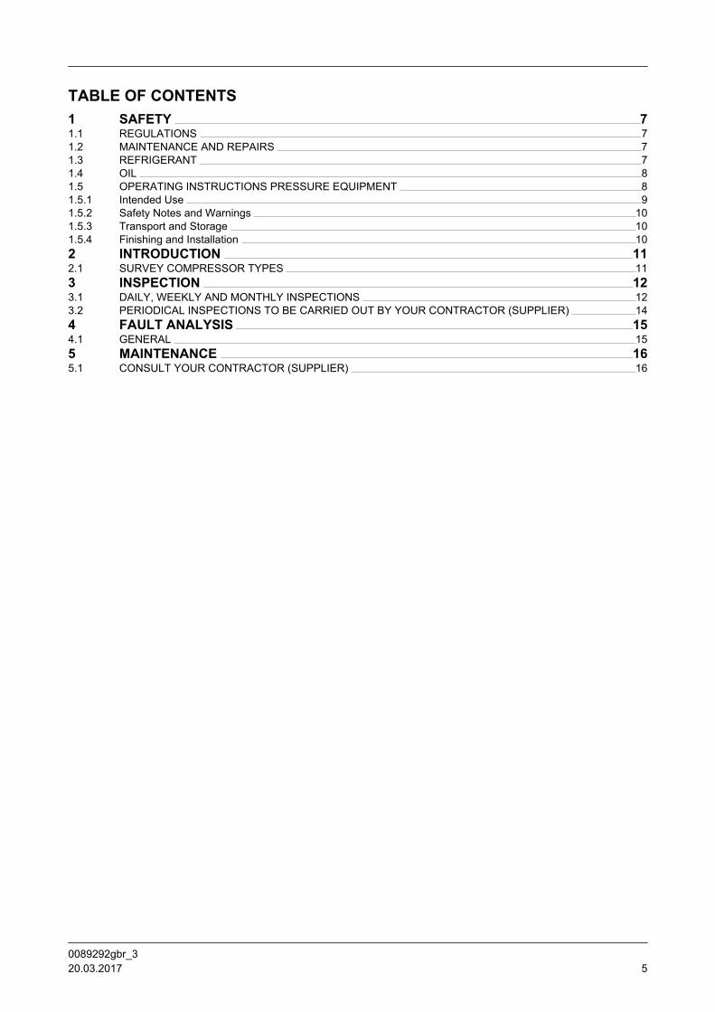
TABLE OF CONTENTS1 SAFETY 71.1 REGULATIONS 71.2 MAINTENANCE AND REPAIRS 71.3 REFRIGERANT 71.4 OIL 81.5 OPERATING INSTRUCTIONS PRESSURE EQUIPMENT 81.5.1 Intended Use 91.5.2 Safety Notes and Warnings 101.5.3 Transport and Storage 101.5.4 Finishing and Installation 102 INTRODUCTION 112.1 SURVEY COMPRESSOR TYPES 113 INSPECTION 123.1 DAILY, WEEKLY AND MONTHLY INSPECTIONS 123.2 PERIODICAL INSPECTIONS TO BE CARRIED OUT BY YOUR CONTRACTOR (SUPPLIER) 144 FAULT ANALYSIS 154.1 GENERAL 155 MAINTENANCE 165.1 CONSULT YOUR CONTRACTOR (SUPPLIER) 16
0089292gbr_3 20.03.2017 5

0089292gbr_36 20.03.2017
1 SAFETY
1.1 REGULATIONS
Hint!
It is the task of the contractor (supplier) to inform and explain to youas user, about the operation of the compressor (Package).Do respect all international, federal, state and local safety regulations/legislations during inspection, trouble shooting and operating thiscompressor (package).
1.2 MAINTENANCE AND REPAIRS
Warning
All maintenance and repairs have to be carried out only by yourcontractor (supplier), except the maintenance as explicitly mentionedin this manual.Do not open the compressor for service.
Caution!
In compliance with the regulations of the Pressure EquipmentDirective it is mandatory that no changes be made to the constructionof pressurised parts such as the crankcase housing, suction filterhousing, oil separator(s), etc.After having run the initial 100 operating hours,it is essential (in bothnew and modified plants) to replace the running-in filter element withthe permanent filter element supplied. This operation is only to becarried out by well-trained and qualified personnel. Consult yoursupplier to carry out this service.This manual includes a check list for daily, weekly and monthlyinspections. Temperatures and pressures need to be checked atseveral point (eg setting of all pressure safety switches). In case thismanual does not give these values then your contractor (supplier)should instruct you with regard to their correct setiings. Whenreference is made to the plant manual, your contractor (supplier)should take care that your are instructed in being able to undertakeproper inspections and trouble shooting.
Hint!
In case of shut downs longer than 1 month, it is advisable to putwarning labels on vital parts of the compressor saying that the plant isout-of-operation and must not be started up. Consult your contractor(supplier).
1.3 REFRIGERANT
SAFETYREGULATIONS
0089292gbr_3 20.03.2017 7
The compressor/package must be filled with “REFRIGERANT“, to be able tooperate.
Warning
For safety instructions in relation to the refrigerant used in thisrefrigeration plant, refer to separate information, to be supplied byyour contractor (supplier).
1.4 OIL
The compressor/package must be filled with oil, to be able to operate.
Warning
For safety instructions in relation to the oil used in this refrigerationplant, refer to separate information, to be supplied by your contractor(supplier).
1.5 OPERATING INSTRUCTIONS PRESSURE EQUIPMENT
Hint!
For pressure equipment (oil separator OS, housing suction gasstrainer, Economizer ICH, compressor package) manufactured byGrasso according to the European Parliament"s and the EuropeanCouncil"s Pressure Equipment Directive 97/23/EG of 29 May 1997
General
The following operating instructions according to the European PressureEquipment Directive No. 97/23/EG (subsequently referred to as PED) describehow to handle the pressure equipment for finishing and installation.The pressure equipment is intended for installation in compressor packages orrefrigeration plants and can be equipped with specific accessories duringinstallation by the customer.The pressure equipment has been manufactured according to the requirementsof the PED. Its design meets the requirements of the AD2000 regulations.If applicable the finisher/installer (at installation in compressor package orrefrigeration plants and equipping ready for operation) is obliged to prepare hisown risk analysis and operating manual according to the European PressureEquipment Directive 97/23/EG.
The type plates for identification of the pressure equipment looks like this:
SAFETYOIL
0089292gbr_38 20.03.2017
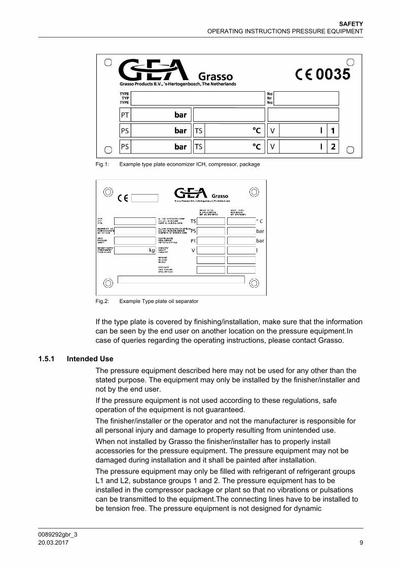
Fig.1: Example type plate economizer ICH, compressor, package
Fig.2: Example Type plate oil separator
If the type plate is covered by finishing/installation, make sure that the informationcan be seen by the end user on another location on the pressure equipment.Incase of queries regarding the operating instructions, please contact Grasso.
1.5.1 Intended UseThe pressure equipment described here may not be used for any other than thestated purpose. The equipment may only be installed by the finisher/installer andnot by the end user.If the pressure equipment is not used according to these regulations, safeoperation of the equipment is not guaranteed.The finisher/installer or the operator and not the manufacturer is responsible forall personal injury and damage to property resulting from unintended use.When not installed by Grasso the finisher/installer has to properly installaccessories for the pressure equipment. The pressure equipment may not bedamaged during installation and it shall be painted after installation.The pressure equipment may only be filled with refrigerant of refrigerant groupsL1 and L2, substance groups 1 and 2. The pressure equipment has to beinstalled in the compressor package or plant so that no vibrations or pulsationscan be transmitted to the equipment.The connecting lines have to be installed tobe tension free. The pressure equipment is not designed for dynamic
SAFETYOPERATING INSTRUCTIONS PRESSURE EQUIPMENT
0089292gbr_3 20.03.2017 9
loads.Where there is a risk of lightning strikes, the pressure equipment must beearthed. The finisher/installer has to include instructions for regular inspection ofthe pressure equipment in his instruction manual and has to define the enduser"s behaviour in case of damage.To avoid burns or frostbite, the pressure vessel may not be touched in theoperating state. This can be achieved by means of contact guards. Installappropriate warning signs.
Caution!
Optionally supplied safety valves are only intended for the protectionof the oil separator against excessive presssure caused by an externalheat source during standstill. This device may not be used for theprotection of the complete refrigeration system. (The finisher/installerhas to equip the installation with a safety valve acc. EN 378)
The oil separator may only be installed vertically. The foundation has to be ofsufficient stiffness.
1.5.2 Safety Notes and WarningsVisually inspect the pressure equipment with the naked eye for corrosion, scoringand similar damage.Check the equipment for shape consistency of the connection areas. In particularcheck and assess the sealing surfaces for possible damage such as scratches,scoring or similar.Keep corrosive substances such as acids away from the oil separator.Wall thicknesses may be no more than 1 mm less than those given in thedrawing.Drain or suck off the medium (refrigerant/oil) prior to service and repair. Thesetasks may only be carried out by trained professionals and in compliance with theappropriate safety regulations, see standard EN 378.Carry out a detailed check of the previous operating history, when an oilseparator that has already been in service is newly finished, installed andequipped. This includes visual inspection (as described above for the new part).For recurring tests please refer to EN 378 T1 to T4 and local regulations.
1.5.3 Transport and StorageTransport and store the oil separator in a dry environment. Ensure that the oilseparator is not subject to damage relevant to its further use.In case of transport damage notify Grasso immediately.
1.5.4 Finishing and InstallationDesign details can be seen in drawings at Grasso.Compare the identification (type plate) with the documentation included in thedelivery before finishing, installing and equipping the oil separator. Mark the oilseparator with the note "Do not use" until the issue has been resolved withGrasso or an authorised third party (named authority according to the PED).
SAFETY
0089292gbr_310 20.03.2017
2 INTRODUCTION
2.1 SURVEY COMPRESSOR TYPES
General
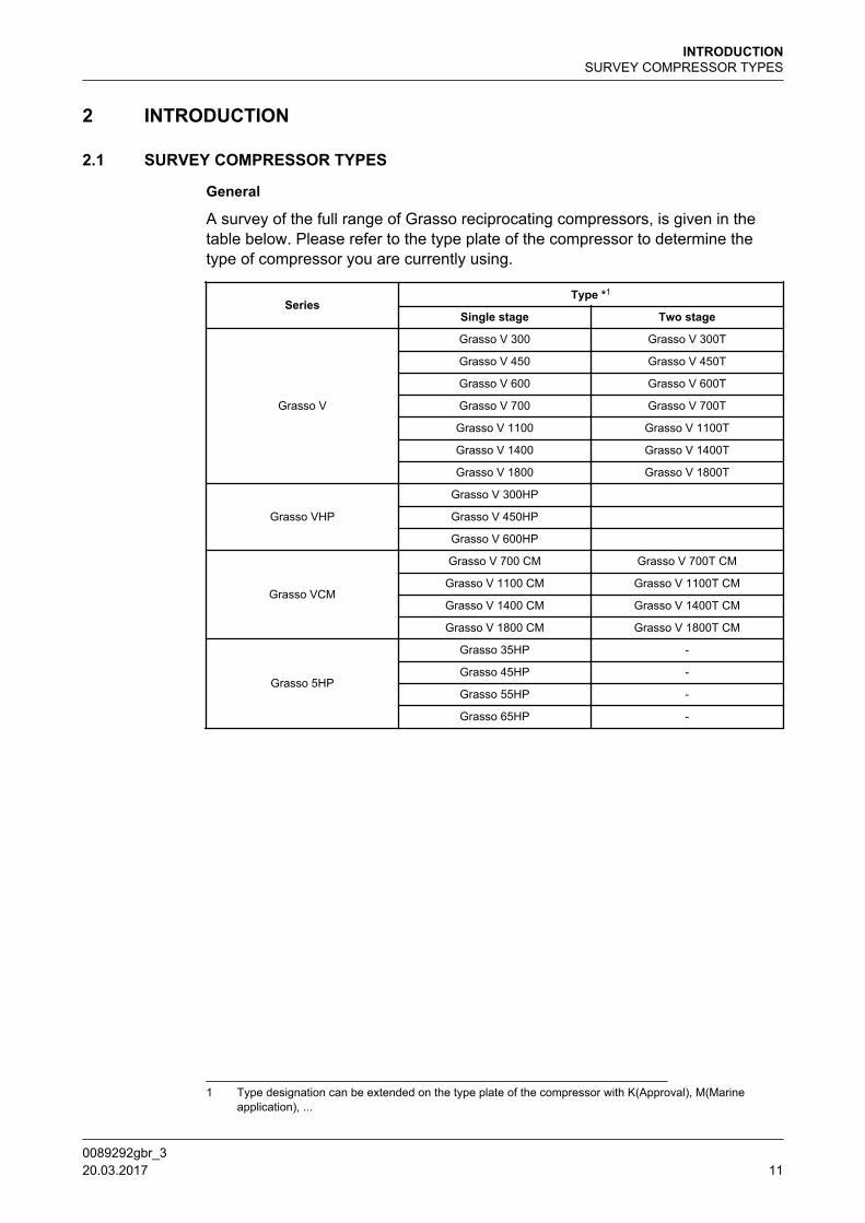
A survey of the full range of Grasso reciprocating compressors, is given in thetable below. Please refer to the type plate of the compressor to determine thetype of compressor you are currently using.
SeriesType *1
Single stage Two stage
Grasso V
Grasso V 300 Grasso V 300T
Grasso V 450 Grasso V 450T
Grasso V 600 Grasso V 600T
Grasso V 700 Grasso V 700T
Grasso V 1100 Grasso V 1100T
Grasso V 1400 Grasso V 1400T
Grasso V 1800 Grasso V 1800T
Grasso VHP
Grasso V 300HP Grasso V 450HP Grasso V 600HP
Grasso VCM
Grasso V 700 CM Grasso V 700T CM
Grasso V 1100 CM Grasso V 1100T CM
Grasso V 1400 CM Grasso V 1400T CM
Grasso V 1800 CM Grasso V 1800T CM
Grasso 5HP
Grasso 35HP -
Grasso 45HP -
Grasso 55HP -
Grasso 65HP -
1 Type designation can be extended on the type plate of the compressor with K(Approval), M(Marineapplication), ...
INTRODUCTIONSURVEY COMPRESSOR TYPES
0089292gbr_3 20.03.2017 11
3 INSPECTION
3.1 DAILY, WEEKLY AND MONTHLY INSPECTIONS
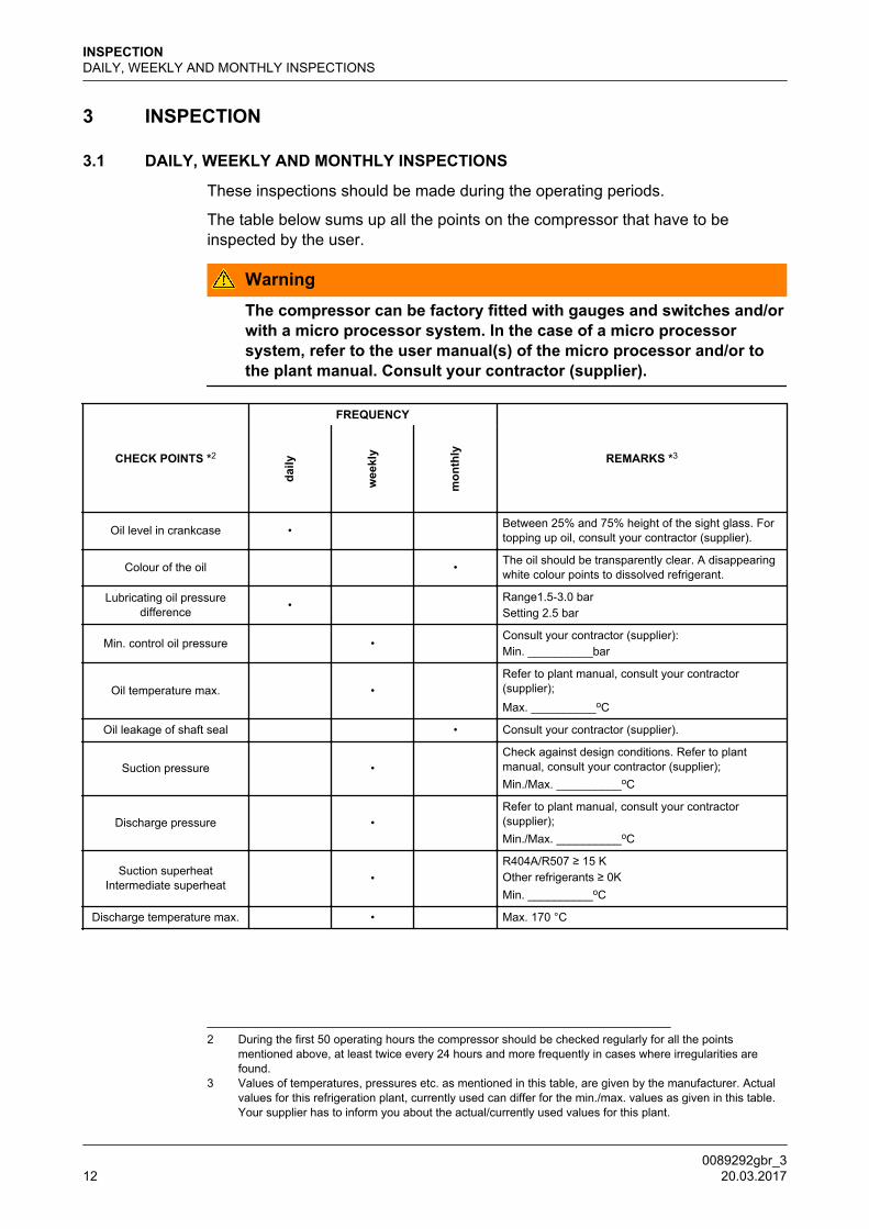
These inspections should be made during the operating periods.
The table below sums up all the points on the compressor that have to beinspected by the user.
Warning
The compressor can be factory fitted with gauges and switches and/orwith a micro processor system. In the case of a micro processorsystem, refer to the user manual(s) of the micro processor and/or tothe plant manual. Consult your contractor (supplier).
CHECK POINTS *2
FREQUENCY
REMARKS *3
daily
wee
kly
mon
thly
Oil level in crankcase • Between 25% and 75% height of the sight glass. Fortopping up oil, consult your contractor (supplier).
Colour of the oil • The oil should be transparently clear. A disappearingwhite colour points to dissolved refrigerant.
Lubricating oil pressuredifference •
Range1.5-3.0 barSetting 2.5 bar
Min. control oil pressure • Consult your contractor (supplier):Min. __________bar
Oil temperature max. • Refer to plant manual, consult your contractor(supplier);Max. __________oC
Oil leakage of shaft seal • Consult your contractor (supplier).
Suction pressure • Check against design conditions. Refer to plantmanual, consult your contractor (supplier);Min./Max. __________oC
Discharge pressure • Refer to plant manual, consult your contractor(supplier);Min./Max. __________oC
Suction superheatIntermediate superheat •
R404A/R507 ≥ 15 KOther refrigerants ≥ 0KMin. __________oC
Discharge temperature max. • Max. 170 °C
2 During the first 50 operating hours the compressor should be checked regularly for all the pointsmentioned above, at least twice every 24 hours and more frequently in cases where irregularities arefound.
3 Values of temperatures, pressures etc. as mentioned in this table, are given by the manufacturer. Actualvalues for this refrigeration plant, currently used can differ for the min./max. values as given in this table.Your supplier has to inform you about the actual/currently used values for this plant.
INSPECTIONDAILY, WEEKLY AND MONTHLY INSPECTIONS
0089292gbr_312 20.03.2017
CHECK POINTS *2
FREQUENCY
REMARKS *3
daily
wee
kly
mon
thly
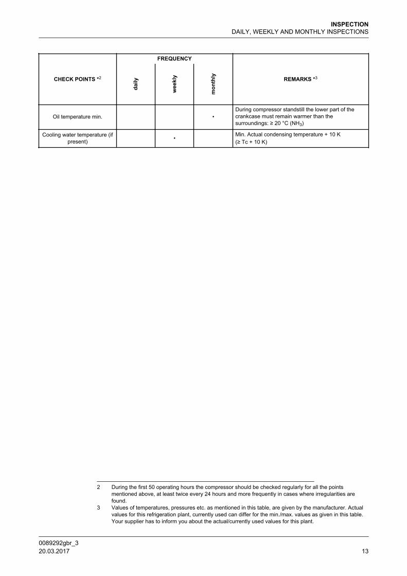
Oil temperature min. •During compressor standstill the lower part of thecrankcase must remain warmer than thesurroundings: ≥ 20 °C (NH3)
Cooling water temperature (ifpresent) •
Min. Actual condensing temperature + 10 K(≥ Tc + 10 K)
2 During the first 50 operating hours the compressor should be checked regularly for all the pointsmentioned above, at least twice every 24 hours and more frequently in cases where irregularities arefound.
3 Values of temperatures, pressures etc. as mentioned in this table, are given by the manufacturer. Actualvalues for this refrigeration plant, currently used can differ for the min./max. values as given in this table.Your supplier has to inform you about the actual/currently used values for this plant.
INSPECTIONDAILY, WEEKLY AND MONTHLY INSPECTIONS
0089292gbr_3 20.03.2017 13
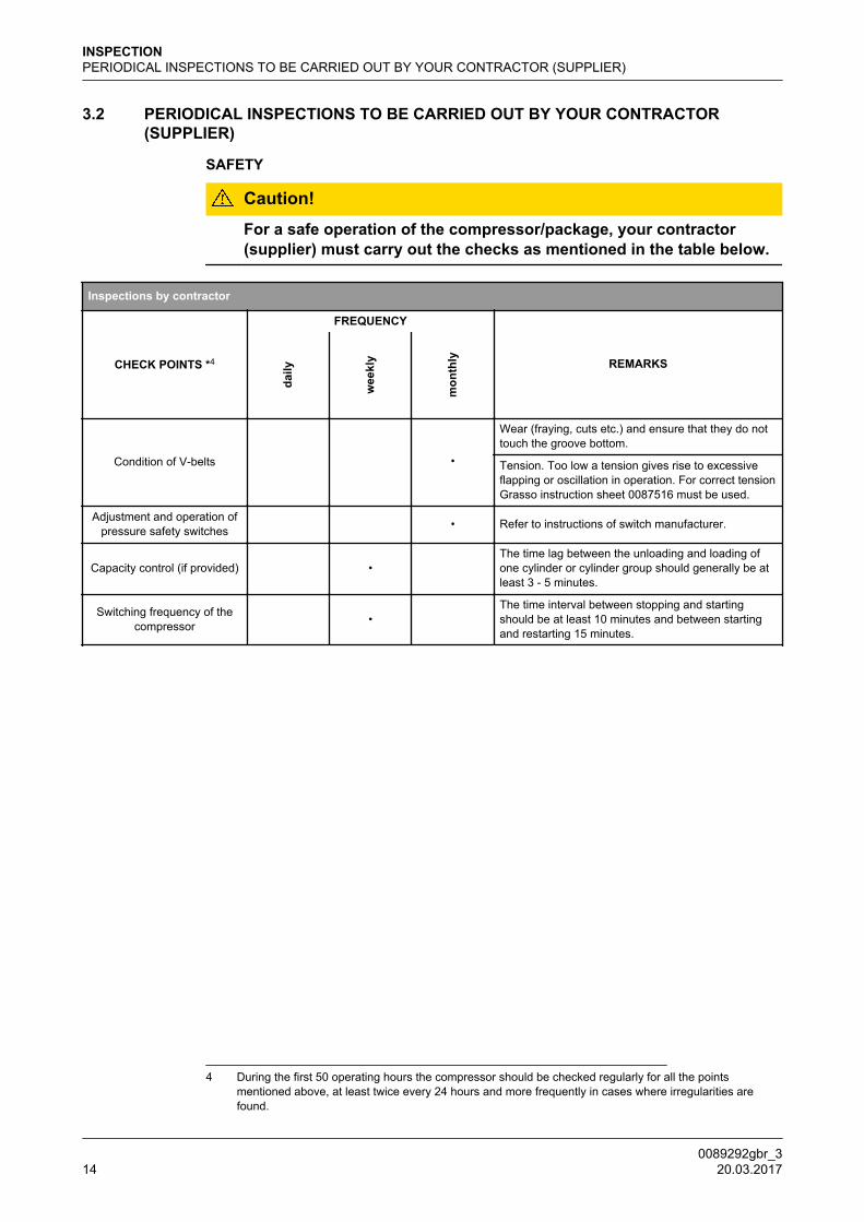
3.2 PERIODICAL INSPECTIONS TO BE CARRIED OUT BY YOUR CONTRACTOR(SUPPLIER)
SAFETY
Caution!
For a safe operation of the compressor/package, your contractor(supplier) must carry out the checks as mentioned in the table below.
Inspections by contractor
CHECK POINTS *4
FREQUENCY
REMARKS
daily
wee
kly
mon
thly
Condition of V-belts •
Wear (fraying, cuts etc.) and ensure that they do nottouch the groove bottom.
Tension. Too low a tension gives rise to excessiveflapping or oscillation in operation. For correct tensionGrasso instruction sheet 0087516 must be used.
Adjustment and operation ofpressure safety switches • Refer to instructions of switch manufacturer.
Capacity control (if provided) • The time lag between the unloading and loading ofone cylinder or cylinder group should generally be atleast 3 - 5 minutes.
Switching frequency of thecompressor •
The time interval between stopping and startingshould be at least 10 minutes and between startingand restarting 15 minutes.
4 During the first 50 operating hours the compressor should be checked regularly for all the pointsmentioned above, at least twice every 24 hours and more frequently in cases where irregularities arefound.
INSPECTIONPERIODICAL INSPECTIONS TO BE CARRIED OUT BY YOUR CONTRACTOR (SUPPLIER)
0089292gbr_314 20.03.2017
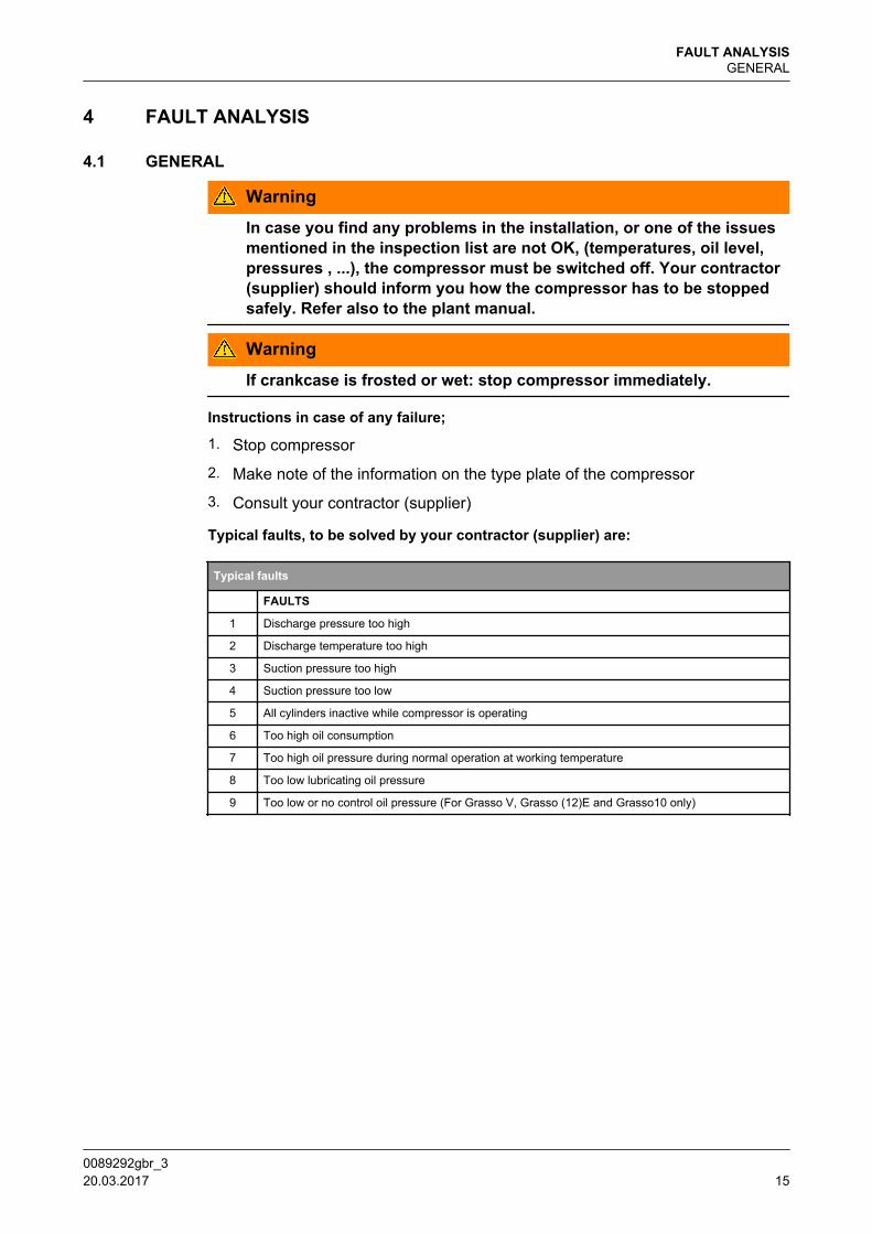
4 FAULT ANALYSIS
4.1 GENERAL
Warning
In case you find any problems in the installation, or one of the issuesmentioned in the inspection list are not OK, (temperatures, oil level,pressures , ...), the compressor must be switched off. Your contractor(supplier) should inform you how the compressor has to be stoppedsafely. Refer also to the plant manual.
Warning If crankcase is frosted or wet: stop compressor immediately.
Instructions in case of any failure;
1. Stop compressor
2. Make note of the information on the type plate of the compressor
3. Consult your contractor (supplier)
Typical faults, to be solved by your contractor (supplier) are:
Typical faults
FAULTS
1 Discharge pressure too high
2 Discharge temperature too high
3 Suction pressure too high
4 Suction pressure too low
5 All cylinders inactive while compressor is operating
6 Too high oil consumption
7 Too high oil pressure during normal operation at working temperature
8 Too low lubricating oil pressure
9 Too low or no control oil pressure (For Grasso V, Grasso (12)E and Grasso10 only)
FAULT ANALYSISGENERAL
0089292gbr_3 20.03.2017 15
5 MAINTENANCE
5.1 CONSULT YOUR CONTRACTOR (SUPPLIER)
All maintenance works are only to be carried out by the contractor (supplier).
Example of works to be carried out by your contractor;
1. Leak testing
2. Evacuation, drying the refrigeration system
3. Initial oil charging
4. Initial refrigerant charging
5. Adjustment of all safety devices
6. Checking direction of rotation compressor
7. Installing drive guard
8. Initial start of the compressor
9. Preparing the compressor for a shut down period (>6 months)
10. Topping up oil
11. Draining and change of oil
12. Evacuation and purging compressor
13. Replacement of filters
14. Reset GMM (Grasso Maintenance Monitor)
15. Adjustment V-belt tension
MAINTENANCECONSULT YOUR CONTRACTOR (SUPPLIER)
0089292gbr_316 20.03.2017
MAINTENANCE
0089292gbr_3 20.03.2017 17
© G
EA G
roup
AG
. All
right
s re
serv
ed. S
ubje
ct to
mod
ifica
tion
GEA Refrigeration Technologies
GEA Refrigeration Netherlands N.V.
Parallelweg 27, 5223 AL ‘s-Hertogenbosch, The NetherlandsPhone: +31 73 [email protected], www.gea.com
GEA Group is a global engineering company with multi-billion euro sales and operations in more than 50 countries. Founded in 1881, the company is one of the largest providers of innovative equipment and process technology. GEA Group is listed in the STOXX® Europe 600 Index.
We live our values.Excellence • Passion • Integrity • Responsibility • GEA-versity