
GRASS Sensomatic
72
SENSOMATIC OPENING SYSTEM Electro-mechanical opening of drawers and pot drawers. Striking a balance between design and functional comfort.
-
Upload
sigma-plus-concept-store -
Category
Documents
-
view
241 -
download
0
description
GRASS Sensomatik sistemi ladica
Transcript of GRASS Sensomatic

F147
1005
2700
0 –
05|2
009
–5.
000
(EN
G) –
GR
ASS
Pro
mot
ion
Subj
ect t
o ch
ange
s, n
o lia
bilit
y fo
r pr
intin
g er
rors
SENSOMATIC OPENING SYSTEM
Electro-mechanical opening of drawers and pot drawers.Striking a balance between design and functional comfort.
Grass GmbH Movement-SystemsGrass Platz 1A 6973 Höchst, AustriaPhone +43 (0) 5578 701-0Fax +43 (0) 5578 701-59E-Mail [email protected]

In an ideal situation, the development of new movement systems directly involves the users of the system. Sensomatic provides the ideal example.
71
SynchronisationskabelTechnical Data
Area of application
Power supply unit
Opening unit
Operating conditions
Drawer systems
Slide systems
Area of application
Power supply
Mains frequency
Max. power output
Supply voltage
Temperature
Humidity
Nova Pro
DWD-Dynamic-XP
Dynapro
only in dry, closed rooms
100 to 240 V
50 to 60 Hz
230 W
24 V
0 to 50 °C
15% to 90%
non-condensing
Flat
tim
ber
cros
s-ba
rU
prig
ht t
imbe
rcr
oss-
bar
Hea
d as
sem
bly
Back
pan
el
asse
mbl
ySi
nk c
abin
etas
sem
bly
of b
ase
Sink
cab
inet
asse
mbl
y of
sid
esA
djus
tmen
t /
Dis
man
tlin
gA
cces
soir
ies
Tech
nica
lin
form
atio
n

3
Comfort with a fascinating twist: it is enough to lightly touch or pull – and the drawers will open as if by magic. Fully automatic, electrically powered.
Thanks to the touch-sensitive Sensomatic device all
you need is a gentle trigger to automatically open
drawers and pot drawers. The action is even, precise
and elegant. And yet, Sensomatic is extremely frugal.
This applies to power consumption as well as space
occupied by the drive unit behind the drawer.
This opening system can be activated by a touch
anywhere on the front of the drawer, which makes
Sensomatic the perfect movement system today,
for the functional requirements of tomorrow.
Likewise, Sensomatic offers ideal solutions for the
furniture designer: the electro-mechanical opening
system allows the use of handle-free surfaces,
clean lines and simple elegance of form. However,
that is not all. Sensomatic makes sure that each
movement offers something for the senses, so that
functional precision also adds an emotional ingre-
dient to your lifestyle. And what an ingredient. The
furniture becomes an expression of your personality,
an element of self-realisation and sensual art.
This electro-mechanical opening system can be triggered by a light touch or pullanywhere on the surface of the front whichcauses drawers to glide evenly and smoothly.
SENSOMATIC OPENING SYSTEM

4
It has never been easier to open a drawer.
And it has never been easier to close
a drawer. Sensomatic and Soft-close
combine to form a harmonious multi-
functional principle. The two systems
combine all advantages of handle-free
opening with the elegance of damped
closing. The combination of these
extraordinary functions guarantees
operating comfort of the highest level.
It is good that there are things thatare made for each other.
Two devices in one: Sensomatic, the electro-mechanical opening system, and Soft-close the mechanical damping system - a symbiosis for maximum comfort in all parts of the home.

5
SENSOMATIC OPENING SYSTEM
How about a single opening system for all applications?We have it here: Sensomatic can be used to open all GRASS systems. Whether we are talking aboutdouble-walled drawers or wooden drawers.
Versatility clearly increases the efficiency of a system. The same applies to movement systems.
Sensomatic is a highly efficient system
as it needs only one drive unit for all
weight classes and cabinet widths up
to 1,200 mm. But that is not all. This
electro-mechanical opening system
can also be combined with all drawer
and slide systems by GRASS. And
without having to modify the drawers
in question. Likewise, other items
such as wire baskets, refuse separa-
ting systems or larder cupboards can
be fitted with the Sensomatic system
without modifications for comfortable
easy opening. In short: Sensomatic
is an electro-mechanical multi-talented
device. Versatile. Efficient. Compelling.
The Sensomatic opening systemis available for GRASS Nova Prodrawer systems, GRASS DWD-Dynamic-XP drawer systems andGRASS Dynapro slide system.
One single opening system for all drawer and
slide systems by GRASS. Sensomatic is an
electro-mechanical device with many talents
for modern furniture.
Nova Pro DWD-Dynamic-XP Dynapro

6
SensomaticTable of contents
Standard cabinet with horizontal wooden stretcher
Nova Pro construction
DWD-Dynamic-XP construction
Dynapro construction
Assembly
8
10
12
14
16
Standard cabinet with vertical wooden stretcher
Nova Pro construction
DWD-Dynamic-XP construction
Dynapro construction
Assembly
Single drawer with overhead frame set mounting
Nova Pro construction
DWD-Dynamic-XP construction
Dynapro construction
Assembly
Single drawer with back panel frame set mounting
Nova Pro construction
DWD-Dynamic-XP construction
Dynapro construction
Assembly
page
18
20
22
24
26
28
30
32
34
36
38
40
42
44
46

7
Technical notes
page
Sink cabinet with bottom panel frame set mounting
Nova Pro construction
DWD-Dynamic-XP construction
Dynapro construction
Assembly
Sink cabinet with side panel frame set mounting
Nova Pro construction
DWD-Dynamic-XP construction
Assembly
Adjustment and dismantling
Accessories
Front-base connector4-way-adapterSynchronisation cableDrilling template
48
50
52
54
56
58
60
62
64
66
68
70

8
SensomaticStandard cabinet with horizontal wooden stretcher
Adjustment and Dismantling page 66 Technical Information page 70
Accessories page 68
Accessories and assembly aides
Example for ordering:The following items are needed for a cabinet with 3 drawers:
Opening units: 3 No. Power supply unit: 1 No.
Frame sides: 1 pair Mains cable: 1 No.
Frame connector: 2 No. Front buffers: 10 No.
Frame set: 2 No.
1
34
2
4
3
5
6
78
1
2
3
5
7
8
4

9
Item No. Item No.
for Nova Pro and Dynapro F121100268217 F121100268607
for DWD-Dynamic-XP F121100409217 F121100409607
PU 50 PU 10
PU 50 = 50 pieces, PU 10 = 10 pieces, individually packaged
1 Opening unit
5 Power supply unit
Item No.
Frame set F121100270211
PU 20
PU 20 = 20 pieces
Item No.
Power supply unit F121100269607
PU 10
PU 10 = 10 Stück, individually packaged
7 Mains cables
Type of plug Item No.
Mains cable K (USA, JP, CA) 69760-04
Mains cable A (DE, ES, F) 69761-04
Mains cable E (DK) 69763-04
Mains cable I (IT) 69764-04
Mains cable L (CH) 69765-04
Mains cable D (G, VAE, MY) 69766-04
without plug 69767-04
PU 10
PU 10 = 10 pieces
6 Connection cable with 2-way-adapter
Length Item No.
600 mm F121100288207
1000 mm F121100289207
1600 mm F121100290207
2000 mm F121100291207
PU 10
PU 10 = 10 pieces
8 Spring-loaded front buffer
Ø 5 mm Item No.
Front gap 2,2 mm* F121100294223
Front gap 3 mm F121100295223
Front gap 4 mm F121100296223
Ø 8 mm Item No.
Front gap 2,2 mm* F121100297223
Front gap 3 mm F121100298223
Front gap 4 mm F121100299223
PU 100
PU 100 = 100 pieces, *for Nova Pro and Dynapro
4 Fixing brackets, top and bottom
Item No.
Frame connector F121100282211
PU 20
PU 20 = 20 pieces
3 Frame connector
Length Item No.
650 mm F121100284207
750 mm F121100285207
1170 mm F121100286207
PU 10
PU 10 = 10 pairs
2 Frame sides, including frame side cable
K A E
I L D
Flat
tim
ber
cros
s-ba
rU
prig
ht t
imbe
rcr
oss-
bar
Hea
d as
sem
bly
Back
pan
el
asse
mbl
ySi
nk c
abin
etas
sem
bly
of b
ase
Sink
cab
inet
asse
mbl
y of
sid
esA
djus
tmen
t /
Dis
man
tlin
gA
cces
soir
ies
Tech
nica
lin
form
atio
n

10
Standard cabinet with horizontal wooden stretcherNova Pro drawer system
All dimensions in millimeters.
Overview
X = min. installation depth
Y = depth of hole pattern
KIB = internal width of cabinet
A = Frame set top/bottom
B = Frame connector
C = Frame sides
NL = nominal length of cabinet slide
Ø10
52
10
96
160
Ø 5 / 5min.
X
Y
1/2 1/2
96
160
15
KIB
Positioning aid
Cable routing
YX
KIB
Mounting dimensions Nova Pro X Y
Steel back panel NL + 18 NL + 3
Wood back panel NL + 20 (+1) NL + 5 (+1)
A
A
B
B
C
Mounting dimensions
Fixing brackets top/bottom

11
All dimensions in millimeters.
Position of front buffer
Cutting frame side
Position of opening units Nova Pro
min
. 49,
5
4-1
010
min
. 50
TL =
KIH
- 31
KIH
10
KIB (min. 262)
200
2020
FH ≤
300
FA
FA / 2
min. 11
Ø8 (Ø5) ±0,1
FA
FA / 2
min. 11
1/2FH
≤ 3
00
1/2
Ø8 (Ø5) ±0,1
When fitting the heavy-duty cabinet slide (70 kg)
4 No. front buffers have to be inserted into the front.
Do not drive in or glue front buffers.
FH = height of front
FA = front overlap
KIH = internal height of cabinet
TL = length of frame side
KIB = internal width of cabinet
TL = Length of frame side
TL
Flat
tim
ber
cros
s-ba
rU
prig
ht t
imbe
rcr
oss-
bar
Hea
d as
sem
bly
Back
pan
el
asse
mbl
ySi
nk c
abin
etas
sem
bly
of b
ase
Sink
cab
inet
asse
mbl
y of
sid
esA
djus
tmen
t /
Dis
man
tlin
gA
cces
soir
ies
Tech
nica
lin
form
atio
n

12
Standard cabinet with horizontal wooden stretcherDWD-Dynamic-XP drawer system
Overview
X = min. installation depth
Y = depth of hole pattern
KIB = internal width of cabinet
Ø10
52
10
96
160
Ø 5 / 5min.
X
Y
1/2 1/2
96
160
15
KIB
Positioning aid
Cable routing
YX
KIB
Mounting dimensions DWD-Dynamic-XP X Y
Steel back panel NL + 13 NL - 2
Wood back panel NL + 15 NL
All dimensions in millimeters.
A = Frame set top/bottom
B = Frame connector
C = Frame sides
A
A
B
B
C
Mounting dimensions
NL = nominal length of cabinet slide
Fixing brackets top/bottom

13
All dimensions in millimeters.
Position of opening unit DWD-Dynamic-XP Position of front buffer
5-10
min
. 55
min
. 49
1010
TL =
KIH
- 31
KIH
KIB (min. 262)
200
2020
FH ≤
300
FA
FA / 2
min. 11
Ø8 (Ø5) ±0,1
FA
FA / 2
min. 11
1/2FH
≤ 3
00
1/2
Ø8 (Ø5) ±0,1
Cutting frame side
TL = Length of frame side
Cutting frame side
When fitting the heavy-duty cabinet slide (60 kg and 80 kg)
4 No. front buffers have to be inserted into the front.
Do not drive in or glue front buffers.
FH = height of front
FA = front overlap
KIH = internal height of cabinet
TL = length of frame side
KIB = internal width of cabinet
TL
Flat
tim
ber
cros
s-ba
rU
prig
ht t
imbe
rcr
oss-
bar
Hea
d as
sem
bly
Back
pan
el
asse
mbl
ySi
nk c
abin
etas
sem
bly
of b
ase
Sink
cab
inet
asse
mbl
y of
sid
esA
djus
tmen
t /
Dis
man
tlin
gA
cces
soir
ies
Tech
nica
lin
form
atio
n

14
Standard cabinet with horizontal wooden stretcherDynapro slide system
Overview
X = min. installation depth
Y = depth of hole pattern
KIB = internal width of cabinet
Ø10
52
10
96
160
Ø 5 / 5min.
X
Y
1/2 1/2
96
160
15
KIB
Positioning aid
Cable routing
YX
KIB
Mounting dimensions Dynapro X Y
NL + 15 NL
All dimensions in millimeters.
A = Frame set top/bottom
B = Frame connector
C = Frame sides
A
A
B
B
C
Mounting dimensions
NL = nominal length of cabinet slide
Fixing brackets top/bottom

15
All dimensions in millimeters.
Position of opening unit Dynapro Position of front buffer
min
. 37
1515
15
min
. 64
TL =
KIH
-31
KIH
KIB (min. 312)
200
(min
. 88)
2020
FH ≤
300
FA
FA / 2
min. 11
Ø8 (Ø5) ±0,1
FA
FA / 2
min. 11
1/2FH
≤ 3
00
1/2
Ø8 (Ø5) ±0,1
TL = Length of frame side
Cutting frame side
When fitting the heavy-duty cabinet slide (60 kg)
4 No. front buffers have to be inserted into the front.
Do not drive in or glue front buffers.
FH = height of front
FA = front overlap
KIH = internal height of cabinet
TL = length of frame side
KIB = internal width of cabinet
TL
Flat
tim
ber
cros
s-ba
rU
prig
ht t
imbe
rcr
oss-
bar
Hea
d as
sem
bly
Back
pan
el
asse
mbl
ySi
nk c
abin
etas
sem
bly
of b
ase
Sink
cab
inet
asse
mbl
y of
sid
esA
djus
tmen
t /
Dis
man
tlin
gA
cces
soir
ies
Tech
nica
lin
form
atio
n

16
Standard cabinet with horizontal wooden stretcherfor Nova Pro, DWD-Dynamic-XP and Dynapro
Assembly

2
1
3
17
Wiring
Inserting front buffer
Do not drive in or glue front buffers.
Flat
tim
ber
cros
s-ba
rU
prig
ht t
imbe
rcr
oss-
bar
Hea
d as
sem
bly
Back
pan
el
asse
mbl
ySi
nk c
abin
etas
sem
bly
of b
ase
Sink
cab
inet
asse
mbl
y of
sid
esA
djus
tmen
t /
Dis
man
tlin
gA
cces
soir
ies
Tech
nica
lin
form
atio
n

18
SensomaticStandard cabinet with vertical wooden stretcher
Adjustment and Dismantling page 66 Technical Information page 70
Accessories page 68
Accessories and assembly aides
1
4
2
5
6
7
89
3
Example for ordering:The following items are needed for a cabinet with 3 drawers:
Opening units: 3 No. Frame set, back: 1 No.
Frame sides: 1 pair Power supply unit: 1 No.
Frame connector: 2 No. Mains cable: 1 No.
Frame set: 1 No. Front buffers: 10 No.
1
2
3
5
6
8
4 9
3

19
Item No. Item No.
for Nova Pro and Dynapro F121100268217 F121100268607
for DWD-Dynamic-XP F121100409217 F121100409607
PU 50 PU 10
PU 50 = 50 pieces, PU 10 = 10 pieces, individually packaged
1 Opening unit
6 Power supply unit
Frame set Item No.
inside mounted F121100275207
PU 10
back mounted F121100276207
PU 10
PU 10 = 10 pieces
Item No.
Power supply unit F121100269607
PU 10
PU 10 = 10 pieces, individually packaged
8 Mains cables
Type of plug Item No.
Mains cables K (USA, JP, CA) 69760-04
Mains cables A (DE, ES, F) 69761-04
Mains cables E (DK) 69763-04
Mains cables I (IT) 69764-04
Mains cables L (CH) 69765-04
Mains cables D (G, VAE, MY)69766-04
without plug 69767-04
PU 10
PU 10 = 10 pieces
7 Connection cable with 2-way-adapter
Length Item No.
600 mm F121100288207
1000 mm F121100289207
1600 mm F121100290207
2000 mm F121100291207
PU 10
PU 10 = 10 pieces
9 Spring-loaded front buffer
Ø 5 mm Item No.
Front gap 2,2 mm* F121100294223
Front gap 3 mm F121100295223
Front gap 4 mm F121100296223
Ø 8 mm Item No.
Front gap 2,2 mm* F121100297223
Front gap 3 mm F121100298223
Front gap 4 mm F121100299223
PU 100
PU 100 = 100 pieces*for Nova Pro and Dynapro
5 Rear-mounting fixing brackets
Item No.
Frame connector F121100282211
PU 20
PU 20 = 20 pieces
3 Frame connector
Length Item No.
650 mm F121100284207
750 mm F121100285207
1170 mm F121100286207
PU 10
PU 10 = 10 pairs
2 Frame sides, including frame side cable
Item No.
Frame set F121100270211
PU 20
PU 20 = 20 pieces
4 Frame set bottom
K A E
I L D
Flat
tim
ber
cros
s-ba
rU
prig
ht t
imbe
rcr
oss-
bar
Hea
d as
sem
bly
Back
pan
el
asse
mbl
ySi
nk c
abin
etas
sem
bly
of b
ase
Sink
cab
inet
asse
mbl
y of
sid
esA
djus
tmen
t /
Dis
man
tlin
gA
cces
soir
ies
Tech
nica
lin
form
atio
n
20
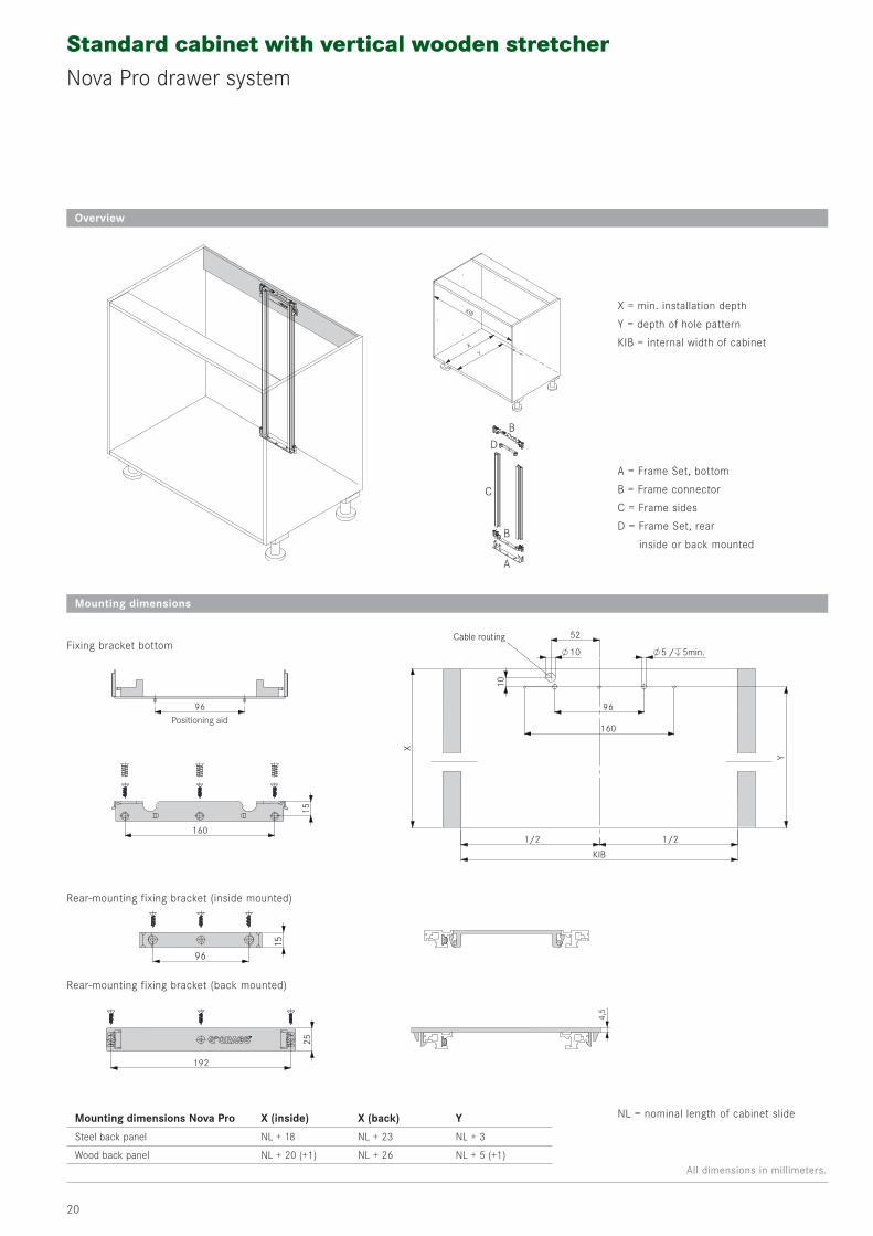
Standard cabinet with vertical wooden stretcherNova Pro drawer system
Overview
X = min. installation depth
Y = depth of hole pattern
KIB = internal width of cabinetY
X
KIB
Mounting dimensions Nova Pro X (inside) X (back) Y
Steel back panel NL + 18 NL + 23 NL + 3
Wood back panel NL + 20 (+1) NL + 26 NL + 5 (+1)
96
160
15
Positioning aid
192
25
4,5
10
52
10
96
160
5 / 5min.
X
Y
1/2 1/2
KIB
Cable routing
96
15
A = Frame Set, bottom
B = Frame connector
C = Frame sides
D = Frame Set, rear
inside or back mounted
A
B
B
C
D
Mounting dimensions
NL = nominal length of cabinet slide
Fixing bracket bottom
Rear-mounting fixing bracket (inside mounted)
Rear-mounting fixing bracket (back mounted)
All dimensions in millimeters.

21
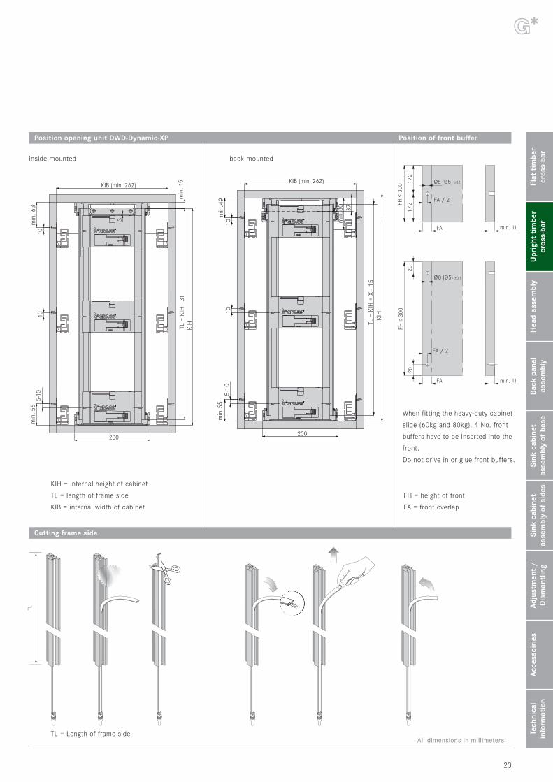
Position opening unit Nova Pro Position of front buffer
Position of Antriebseinheit Nova Pro
min
. 49,
5 4-1
0
200
10
KIB (min. 262)
min
. 50
10
min
. 80
37
TL =
KIH
- 31
KIH
min
. 49,
5 4-1
0
200
10
3
KIH
TL =
KIH
-31
min
. 15
10m
in. 6
3
min
. 80
KIB (min. 262)
2020
FH ≤
300
FA
FA / 2
min. 11
Ø8 (Ø5) ±0,1
FA
FA / 2
min. 11
1/2FH
≤ 3
00
1/2
Ø8 (Ø5) ±0,1
Cutting frame side
TL = Length of frame side
KIH = internal height of cabinet
TL = length of frame side
KIB = internal width of cabinet
When fitting the heavy-duty cabinet
slide (70 kg), 4 No. front buffers
have to be inserted into the front.
Do not drive in or glue front buffers.
FH = height of front
FA = front overlap
TL
Flat
tim
ber
cros
s-ba
rU
prig
ht t
imbe
rcr
oss-
bar
Hea
d as
sem
bly
Back
pan
el
asse
mbl
ySi
nk c
abin
etas
sem
bly
of b
ase
Sink
cab
inet
asse
mbl
y of
sid
esA
djus
tmen
t /
Dis
man
tlin
gA
cces
soir
ies
Tech
nica
lin
form
atio
n
back mountedinside mounted
All dimensions in millimeters.

22
Standard cabinet with vertical wooden stretcherDWD-Dynamic-XP drawer system
Overview
X = min. installation depth
Y = depth of hole pattern
KIB = internal width of cabinetY
X
KIB
Mounting dimensions DWD-Dynamic-XP X (inside) X (back) Y
Steel back panel NL + 13 NL + 18 NL -2
Wood back panel NL + 15 NL + 20 NL
Mounting dimensions
NL = nominal length of cabinet slide
A = Frame Set, bottom
B = Frame connector
C = Frame sides
D = Frame Set, rear
inside or back mounted
A
B
B
C
D
4,5
96
160
15
Positioning aid
192
25
96
15
10
52
10
96
160
5 / 5min.
X
Y
1/2 1/2
KIB
Cable routingFixing bracket bottom
Rear-mounting fixing bracket (inside mounted)
Rear-mounting fixing bracket (back mounted)
All dimensions in millimeters.
23
Position opening unit DWD-Dynamic-XP
5-10
min
. 55
10
KIB (min. 262)
200
min
. 49
10
TL =
KIH
+ X
- 15
KIH
min
. 80
37
Cutting frame side
TL = Length of frame side
KIH = internal height of cabinet
TL = length of frame side
KIB = internal width of cabinet
2020
FH ≤
300
FA
FA / 2
min. 11
Ø8 (Ø5) ±0,1
FA
FA / 2
min. 11
1/2FH
≤ 3
00
1/2
Ø8 (Ø5) ±0,1
When fitting the heavy-duty cabinet
slide (60kg and 80kg), 4 No. front
buffers have to be inserted into the
front.
Do not drive in or glue front buffers.
FH = height of front
FA = front overlap
5-10
min
. 55
10
KIB (min. 262)
200
3
10m
in. 6
3
min
. 15
TL =
KIH
- 31
KIH
Position of front buffer
TL
Flat
tim
ber
cros
s-ba
rU
prig
ht t
imbe
rcr
oss-
bar
Hea
d as
sem
bly
Back
pan
el
asse
mbl
ySi
nk c
abin
etas
sem
bly
of b
ase
Sink
cab
inet
asse
mbl
y of
sid
esA
djus
tmen
t /
Dis
man
tlin
gA
cces
soir
ies
Tech
nica
lin
form
atio
n
back mountedinside mounted
All dimensions in millimeters.

24
Standard cabinet with vertical wooden stretcherDynapro slide-system
Overview
X = min. installation depth
Y = depth of hole pattern
KIB = internal width of cabinetY
X
KIB
Mounting dimensions Dynapro X (inside) X (back) Y
Wood back panel NL + 15 NL + 20 NL
Mounting dimensions
NL = nominal length of cabinet slide
A = Frame Set, bottom
B = Frame connector
C = Frame sides
D = Frame Set, rear
inside or back mounted
A
B
B
C
D
96
160
15
Positioning aid
192
25
96
15
4,5
10
52
10
96
160
5 / 5min.
X
Y
1/2 1/2
KIB
Cable routingFixing bracket bottom
Rear-mounting fixing bracket (inside mounted)
Rear-mounting fixing bracket (back mounted)
All dimensions in millimeters.

25
Position opening unit Dynapro
min
. 37 15
15
KIB (min. 312)
200
min
. 62
15
TL =
KIH
- 31
KIH
min
. 8037
Cutting frame side
TL
TL = Length of frame side
KIH = internal height of cabinet
TL = length of frame side
KIB = internal width of cabinet
Position of front buffer
2020
FH ≤
300
FA
FA / 2
min. 11
Ø8 (Ø5) ±0,1
FA
FA / 2
min. 11
1/2FH
≤ 3
00
1/2
Ø8 (Ø5) ±0,1
When fitting the heavy-duty cabinet
slide (60 kg), 4 No. front buffers
have to be inserted into the front.
Do not drive in or glue front buffers.
FH = height of front
FA = front overlap
min
. 37 15
15
KIB (min. 312)
200
min
. 80
min
. 90
15
TL =
KIH
- 31
KIH
15
3
back mountedinside mounted
Flat
tim
ber
cros
s-ba
rU
prig
ht t
imbe
rcr
oss-
bar
Hea
d as
sem
bly
Back
pan
el
asse
mbl
ySi
nk c
abin
etas
sem
bly
of b
ase
Sink
cab
inet
asse
mbl
y of
sid
esA
djus
tmen
t /
Dis
man
tlin
gA
cces
soir
ies
Tech
nica
lin
form
atio
n
All dimensions in millimeters.

26
Standard cabinet with vertical wooden stretcherfor Nova Pro, DWD-Dynamic-XP and Dynapro
Assembly

2
1
3
27
Wiring
Flat
tim
ber
cros
s-ba
rU
prig
ht t
imbe
rcr
oss-
bar
Hea
d as
sem
bly
Back
pan
el
asse
mbl
ySi
nk c
abin
etas
sem
bly
of b
ase
Sink
cab
inet
asse
mbl
y of
sid
esA
djus
tmen
t /
Dis
man
tlin
gA
cces
soir
ies
Tech
nica
lin
form
atio
n
Inserting front buffer
Do not drive in or glue front buffers.

28
SensomaticSingle drawer with overhead frame set mounting
Adjustment and Dismantling page 66 Technical Information page 70
Accessories page 68
Accessories and assembly aides
1
2
3
4
5
6
Example for ordering:The following items are needed for a cabinet with one drawer:
Opening unit: 1 No. Mains cables: 1 No.
Frame Set for head assembly: 1 No. Front buffer: 2 No.
Power supply unit : 1 No.
1
2
3
5
6

29
Item No. Item No.
for Nova Pro and Dynapro F121100268217 F121100268607
for DWD-Dynamic-XP F121100409217 F121100409607
PU 50 PU 10
PU 50 = 50 pieces, PU 10 = 10 pieces, individually packaged
1 Opening unit
3 Power supply unit
Item No.
Height 120 mm F121100272207
Height 170 mm F121100273207
PU 10
PU 10 = 10 pieces
Item No.
Power supply unit F121100269607
PU 10
PU 10 = 10 pieces, individually packaged
5 Mains cables
Type of plug Item No.
Mains cables K (USA, JP, CA) 69760-04
Mains cables A (DE, ES, F) 69761-04
Mains cables E (DK) 69763-04
Mains cables I (IT) 69764-04
Mains cables L (CH) 69765-04
Mains cables D (G, VAE, MY) 69766-04
without plug 69767-04
PU 10
PU 10 = 10 pieces
4 Connection cable with 2-way-adapter
Length Item No.
600 mm F121100288207
1000 mm F121100289207
1600 mm F121100290207
2000 mm F121100291207
PU 10
PU 10 = 10 pieces
6 Spring-loaded front buffer
Ø 5 mm Item No.
Front gap 2,2 mm* F121100294223
Front gap 3 mm F121100295223
Front gap 4 mm F121100296223
Ø 8 mm Item No.
Front gap 2,2 mm* F121100297223
Front gap 3 mm F121100298223
Front gap 4 mm F121100299223
PU 100
PU 100 = 100 pieces*for Nova Pro and Dynapro
2 Frame set for head assembly
K A E
I L D
Flat
tim
ber
cros
s-ba
rU
prig
ht t
imbe
rcr
oss-
bar
Hea
d as
sem
bly
Back
pan
el
asse
mbl
ySi
nk c
abin
etas
sem
bly
of b
ase
Sink
cab
inet
asse
mbl
y of
sid
esA
djus
tmen
t /
Dis
man
tlin
gA
cces
soir
ies
Tech
nica
lin
form
atio
n

30
Single drawer with overhead frame set mountingNova Pro drawer system
Overview
X = min. installation depth
Y = depth of hole pattern
KIB = internal width of cabinet
160
15
6032
96
114
96
164
Positioning aid
Positioning aid
96
5210m
in. 5
7
Positioning aid
Cabinet base
96
160
5 / 5min.
Y
1/2 1/2
X
32
KIB
YX
KIB
Mounting dimensions Nova Pro X Y
Steel back panel NL + 18 NL + 3
Wood back panel NL + 20 (+ 1) NL + 5 (+1)
Überkopfmontage
Height 170 Back wall cabling
Height 120
Frame Set for head assembly
NL = nominal length of cabinet slide
Mounting dimensions
All dimensions in millimeters.

31
Position of opening unit Nova Pro Position of front buffer
min
. 50
4-10
164
KIB (min. 262)
max
. 108
min
. 50
4-10
114
KIB (min. 262)
max
. 58
2020
FH ≤
300
FA
FA / 2
min. 11
Ø8 (Ø5) ±0,1
FA
FA / 2
min. 11
1/2FH
≤ 3
00
1/2
Ø8 (Ø5) ±0,1
KIB = internal width of cabinet
Height 170
Height 120
When fitting the heavy-duty cabinet slide (70 kg)
4 No. front buffers have to be inserted into the front.
Do not drive in or glue front buffers.
FH = height of front
FA = front overlap
Flat
tim
ber
cros
s-ba
rU
prig
ht t
imbe
rcr
oss-
bar
Hea
d as
sem
bly
Back
pan
el
asse
mbl
ySi
nk c
abin
etas
sem
bly
of b
ase
Sink
cab
inet
asse
mbl
y of
sid
esA
djus
tmen
t /
Dis
man
tlin
gA
cces
soir
ies
Tech
nica
lin
form
atio
n
All dimensions in millimeters.

32
Single drawer with overhead frame set mountingDWD-Dynamic-XP drawer system
Overview
X = min. installation depth
Y = depth of hole pattern
KIB = internal width of cabinet
YX
KIB
Mounting dimensions DWD-Dynamic-XP X Y
Steel back panel NL + 13 NL - 2
Wood back panel NL + 15 NL
160
15
6032
96
114
96
164
Positioning aid
Positioning aid
96
5210m
in. 5
7
Positioning aid
Cabinet base
96
160
5 / 5min.
Y
1/2 1/2
X
32
KIB
Überkopfmontage
Frame Set for head assembly
NL = nominal length of cabinet slide
Height 170
Height 120
Mounting dimensions
Back wall cabling
All dimensions in millimeters.

33
Position of opening unit DWD-Dynamic-XP Position of front buffer
min
. 49
5-10
164
KIB (min. 262)
max
. 107
min
. 49
5-10
114
KIB (min. 262)
max
. 56
2020
FH ≤
300
FA
FA / 2
min. 11
Ø8 (Ø5) ±0,1
FA
FA / 2
min. 11
1/2FH
≤ 3
00
1/2
Ø8 (Ø5) ±0,1
KIB = internal width of cabinet
When fitting the heavy-duty cabinet slide (60kg and 80kg),
4 No. front buffers have to be inserted into the front.
Do not drive in or glue front buffers.
FH = height of front
FA = front overlap
Height 170
Height 120
Flat
tim
ber
cros
s-ba
rU
prig
ht t
imbe
rcr
oss-
bar
Hea
d as
sem
bly
Back
pan
el
asse
mbl
ySi
nk c
abin
etas
sem
bly
of b
ase
Sink
cab
inet
asse
mbl
y of
sid
esA
djus
tmen
t /
Dis
man
tlin
gA
cces
soir
ies
Tech
nica
lin
form
atio
n
All dimensions in millimeters.

34
Single drawer with overhead frame set mountingDynapro slide system
Overview
X = min. installation depth
Y = depth of hole pattern
KIB = internal width of cabinet
YX
KIB
Mounting dimensions Dynapro X Y
Wood back panel NL + 15 NL
160
15
6032
96
114
96
164
Positioning aid
Positioning aid
96
5210m
in. 5
7
Positioning aid
Cabinet base
96
160
5 / 5min.
Y
1/2 1/2
X
32
KIB
Überkopfmontage
Frame Set for head assembly
NL = nominal length of cabinet slide
Height 170
Height 120
Mounting dimensions
Back wall cabling
All dimensions in millimeters.

35
Position of opening unit Dynapro Position of front buffer
min
. 62
11 –
15
164m
ax. 1
22m
in. 6
2
11 –
15
114
KIB (min. 312)
max
. 72
2020
FH ≤
300
FA
FA / 2
min. 11
Ø8 (Ø5) ±0,1
FA
FA / 2
min. 11
1/2FH
≤ 3
00
1/2
Ø8 (Ø5) ±0,1
KIB = internal width of cabinet
When fitting the heavy-duty cabinet slide (60 kg),
4 No. front buffers have to be inserted into the front.
Do not drive in or glue front buffers.
FH = height of front
FA = front overlap
Height 170
Height 120
Flat
tim
ber
cros
s-ba
rU
prig
ht t
imbe
rcr
oss-
bar
Hea
d as
sem
bly
Back
pan
el
asse
mbl
ySi
nk c
abin
etas
sem
bly
of b
ase
Sink
cab
inet
asse
mbl
y of
sid
esA
djus
tmen
t /
Dis
man
tlin
gA
cces
soir
ies
Tech
nica
lin
form
atio
n
All dimensions in millimeters.

36
Single drawer with overhead frame set mountingfor Nova Pro, DWD-Dynamic-XP and Dynapro
Assembly

2
1
3
37
Wiring
Flat
tim
ber
cros
s-ba
rU
prig
ht t
imbe
rcr
oss-
bar
Hea
d as
sem
bly
Back
pan
el
asse
mbl
ySi
nk c
abin
etas
sem
bly
of b
ase
Sink
cab
inet
asse
mbl
y of
sid
esA
djus
tmen
t /
Dis
man
tlin
gA
cces
soir
ies
Tech
nica
lin
form
atio
n
Inserting front buffer
Do not drive in or glue front buffers.

38
SensomaticSingle drawer with back panel frame set mounting
Adjustment and Dismantling page 66 Technical Information page 70
Accessories page 68
Accessories and assembly aides
12
3
4
5
6
7
Example for ordering:The following items are needed for a cabinet with one drawer:
Opening unit: 1 No. Power supply unit : 1 No.
Frame sides: 1 pair Mains cable: 1 No.
Frame connector: 2 No. Front buffers: 2 No.
1
2
3
4
6
7

39
Item No. Item No.
für Nova Pro und Dynapro F121100268217 F121100268607
für DWD-Dynamic-XP F121100409217 F121100409607
PU 50 PU 10
PU 50 = 50 pieces, PU 10 = 10 pieces, individually packaged
1 Opening unit
4 Power supply unit
Item No.
Power supply unit F121100269607
PU 10
PU 10 = 10 pieces, individually packaged
6 Mains cables
Type of plug Item No.
Mains cables K (USA, JP, CA) 69760-04
Mains cables A (DE, ES, F) 69761-04
Mains cables E (DK) 69763-04
Mains cables I (IT) 69764-04
Mains cables L (CH) 69765-04
Mains cables D (G, VAE, MY) 69766-04
without plug 69767-04
PU 10
PU 10 = 10 pieces
5 Connection cable with 2-way-adapter
Length Item No.
600 mm F121100288207
1000 mm F121100289207
1600 mm F121100290207
2000 mm F121100291207
PU 10
PU 10 = 10 pieces
7 Spring-loaded front buffer
Ø 5 mm Item No.
Front gap 2,2 mm* F121100294223
Front gap 3 mm F121100295223
Front gap 4 mm F121100296223
Ø 8 mm Item No.
Front gap 2,2 mm* F121100297223
Front gap 3 mm F121100298223
Front gap 4 mm F121100299223
PU 100
PU 100 = 100 pieces*for Nova Pro and Dynapro
Item No.
Frame connector F121100282211
PU 20
PU 20 = 20 pieces
3 Frame connector
Frame side pair Item No.
for 1 No. Drive F121100283207
including hole drilling
PU 10
PU 10 = 10 pairs
2 Frame sides for back panel assembly
K A E
I L D
Flat
tim
ber
cros
s-ba
rU
prig
ht t
imbe
rcr
oss-
bar
Hea
d as
sem
bly
Back
pan
el
asse
mbl
ySi
nk c
abin
etas
sem
bly
of b
ase
Sink
cab
inet
asse
mbl
y of
sid
esA
djus
tmen
t /
Dis
man
tlin
gA
cces
soir
ies
Tech
nica
lin
form
atio
n

40
Single drawer with back panel frame set mountingNova Pro drawer system
Overview
X = min. installation depth
KIB = internal width of cabinet
X
KIB
Mounting dimensions Nova Pro X
Steel back panel NL + 18
Wood back panel NL + 20 (+1)
X
1/2 1/2
KIB
9
11
52
10
90
45
164
cable routing
Fixing with chipboard screwsø 3,5 - ø 4 (head diameter max. 8)
A = Frame sides
B = Frame connector
Mounting dimensions
NL = nominal length of cabinet slide
A
B
All dimensions in millimeters.

41
Position of opening unit Nova Pro Position of front buffer
min
. 50
4-10
min
. 3m
in. 3
90
KIB (min. 262)
200
2020
FH ≤
300
FA
FA / 2
min. 11
Ø8 (Ø5) ±0,1
FA
FA / 2
min. 11
1/2FH
≤ 3
00
1/2
Ø8 (Ø5) ±0,1
KIB = internal width of cabinet
When fitting the heavy-duty cabinet slide (70 kg)
4 No. front buffers have to be inserted into the front.
Do not drive in or glue front buffers.
FH = height of front
FA = front overlap
Flat
tim
ber
cros
s-ba
rU
prig
ht t
imbe
rcr
oss-
bar
Hea
d as
sem
bly
Back
pan
el
asse
mbl
ySi
nk c
abin
etas
sem
bly
of b
ase
Sink
cab
inet
asse
mbl
y of
sid
esA
djus
tmen
t /
Dis
man
tlin
gA
cces
soir
ies
Tech
nica
lin
form
atio
n
All dimensions in millimeters.

42
Single drawer with back panel frame set mountingDWD-Dynamic-XP drawer system
Overview
X
KIB
X
1/2 1/2
KIB
9
11
52
10
90
45
164
cable routing
Fixing with chipboard screwsø 3,5 - ø 4 (head diameter max. 8)
Mounting dimensions DWD-Dynamic-XP X
Steel back panel NL + 13
Wood back panel NL + 15
Mounting dimensions
NL = nominal length of cabinet slide
A
B
X = min. installation depth
KIB = internal width of cabinet
A = Frame sides
B = Frame connector
All dimensions in millimeters.

43
Position of opening unit DWD-Dynamic-XP Position of front buffer
2020
FH ≤
300
FA
FA / 2
min. 11
Ø8 (Ø5) ±0,1
FA
FA / 2
min. 11
1/2FH
≤ 3
00
1/2
Ø8 (Ø5) ±0,1
min
. 49
5-10
min
. 3m
in. 3
90
KIB (min.262)
200
KIB = internal width of cabinet
When fitting the heavy-duty cabinet slide (60 kg and 80 kg)
4 No. front buffers have to be inserted into the front.
Do not drive in or glue front buffers.
FH = height of front
FA = front overlap
Flat
tim
ber
cros
s-ba
rU
prig
ht t
imbe
rcr
oss-
bar
Hea
d as
sem
bly
Back
pan
el
asse
mbl
ySi
nk c
abin
etas
sem
bly
of b
ase
Sink
cab
inet
asse
mbl
y of
sid
esA
djus
tmen
t /
Dis
man
tlin
gA
cces
soir
ies
Tech
nica
lin
form
atio
n
All dimensions in millimeters.

44
Single drawer with back panel frame set mountingDynapro slide system
Overview
X
KIB
X
1/2 1/2
KIB
9
11
52
10
90
45
164
cable routing
Fixing with chipboard screwsø 3,5 - ø 4 (head diameter max. 8)
Mounting dimensions Dynapro X
Wood back panel NL + 15
Mounting dimensions
NL = nominal length of cabinet slide
A
B
X = min. installation depth
KIB = internal width of cabinet
A = Frame sides
B = Frame connector
All dimensions in millimeters.

45
Position of opening unit Dynapro Position of front buffer
2020
FH ≤
300
FA
FA / 2
min. 11
Ø8 (Ø5) ±0,1
FA
FA / 2
min. 11
1/2FH
≤ 3
00
1/2
Ø8 (Ø5) ±0,1
min
. 390
200
min
. 63
15
min
. 3
KIB (min.312)
KIB = internal width of cabinet
When fitting the heavy-duty cabinet slide (60 kg)
4 No. front buffers have to be inserted into the front.
Do not drive in or glue front buffers
FH = height of front
FA = front overlap
Flat
tim
ber
cros
s-ba
rU
prig
ht t
imbe
rcr
oss-
bar
Hea
d as
sem
bly
Back
pan
el
asse
mbl
ySi
nk c
abin
etas
sem
bly
of b
ase
Sink
cab
inet
asse
mbl
y of
sid
esA
djus
tmen
t /
Dis
man
tlin
gA
cces
soir
ies
Tech
nica
lin
form
atio
n
All dimensions in millimeters.

46
Single drawer with back panel frame set mountingfor Nova Pro, DWD-Dynamic-XP and Dynapro
Assembling

2
1
3
47
Wiring
Flat
tim
ber
cros
s-ba
rU
prig
ht t
imbe
rcr
oss-
bar
Hea
d as
sem
bly
Back
pan
el
asse
mbl
ySi
nk c
abin
etas
sem
bly
of b
ase
Sink
cab
inet
asse
mbl
y of
sid
esA
djus
tmen
t /
Dis
man
tlin
gA
cces
soir
ies
Tech
nica
lin
form
atio
n
Inserting front buffer
Do not drive in or glue front buffers.

48
SensomaticSink cabinet with bottom panel frame set mounting
Adjustment and Dismantling page 66 Technical Information page 70
Accessories page 68
Accessories and assembly aides
1
1
2
2
3
4
7
5
6
Example for ordering:The following items are needed for a cabinet with 2 drawers:
Opening units: 2 No. Mains cables: 1 No.
Base frame Set: 2 No Front buffers: 8 No.
Power supply unit : 1 No.
1
2
3
6
7

49
Item No. Item No.
for Nova Pro and Dynapro F121100268217 F121100268607
for DWD-Dynamic-XP F121100409217 F121100409607
PU 50 PU 10
PU 50 = 50 pieces, PU 10 = 10 pieces, individually packaged
1 Opening unit
3 Power supply unit
Item No.
F121100271207
PU 10
PU 10 = 10 pieces
Item No.
Power supply unit F121100269607
PU 10
PU 10 = 10 pieces, individually packaged
6 Mains cables
Type of plug Item No.
Mains cables K (USA, JP, CA) 69760-04
Mains cables A (DE, ES, F) 69761-04
Mains cables E (DK) 69763-04
Mains cables I (IT) 69764-04
Mains cables L (CH) 69765-04
Mains cables D (G, VAE, MY) 69766-04
without plug 69767-04
PU 10
PU 10 = 10 pieces
4 Connection cable with 2-way-adapter
Length Item No.
600 mm F121100288207
1000 mm F121100289207
1600 mm F121100290207
2000 mm F121100291207
PU 10
PU 10 = 10 pieces
7 Spring-loaded front buffer
Ø 5 mm Item No.
Front gap 2,2 mm* F121100294223
Front gap 3 mm F121100295223
Front gap 4 mm F121100296223
Ø 8 mm Item No.
Front gap 2,2 mm* F121100297223
Front gap 3 mm F121100298223
Front gap 4 mm F121100299223
PU 100
PU 100 = 100 pieces*for Nova Pro and Dynapro
2 Base frame set
5 4-way-adapter
Item No.
4-way-adapter F121100293207
PU 10
PU 10 = 10 pieces
K A E
I L D
Flat
tim
ber
cros
s-ba
rU
prig
ht t
imbe
rcr
oss-
bar
Hea
d as
sem
bly
Back
pan
el
asse
mbl
ySi
nk c
abin
etas
sem
bly
of b
ase
Sink
cab
inet
asse
mbl
y of
sid
esA
djus
tmen
t /
Dis
man
tlin
gA
cces
soir
ies
Tech
nica
lin
form
atio
n

50
Sink cabinet with bottom panel frame set mountingNova Pro drawer system
Overview
X = min. installation depth
Y = depth of hole pattern
Z = depth of hole pattern for sink drawer
KIB = internal width of cabinetY
X
Z
KIB
Mounting dimensions Nova Pro X Y Z
Steel back panel NL + 18 NL + 3 –
Wood back panel NL + 20 (+1) NL + 5 (+1) NL (A) - NL (B) + 9
Base frame set
Mounting dimensions
NL = nominal length of cabinet slide
96
160
ø5 5min.
1/2 1/2
KIB
32m
in. 1
8
min
. 80
Z
X
Positioning aid
/
160
6032
96positioning aid
Ø1052
10
96
160
Ø5 / 5min.
Y
1/2 1/2
X
KIB
32
Cable routing
NL
(A)N
L (B
)
min. 213
Base mounting
Sink mounting
All dimensions in millimeters.

51
Position of opening unit Nova Pro Position of front buffer
min
. 51
4-10min
.52
max
. 63
KIB (min.262)
2020
FH ≤
300
FA
FA / 2
min. 11
Ø8 (Ø5) ±0,1
FA
FA / 2
min. 11
1/2FH
≤ 3
00
1/2
Ø8 (Ø5) ±0,1
KIB = internal width of cabinet
When fitting the heavy-duty cabinet slide (70 kg)
4 No. front buffers have to be inserted into the front.
Do not drive in or glue front buffers.
FH = height of front
FA = front overlap
Flat
tim
ber
cros
s-ba
rU
prig
ht t
imbe
rcr
oss-
bar
Hea
d as
sem
bly
Back
pan
el
asse
mbl
ySi
nk c
abin
etas
sem
bly
of b
ase
Sink
cab
inet
asse
mbl
y of
sid
esA
djus
tmen
t /
Dis
man
tlin
gA
cces
soir
ies
Tech
nica
lin
form
atio
n
All dimensions in millimeters.

52
Sink cabinet with bottom panel frame set mountingDWD-Dynamic-XP drawer system
Overview
Mounting dimensions DWD-Dynamic-XP X Y Z
Steel back panel NL + 13 NL - 2 –
Wood back panel NL + 15 NL NL (A) - NL (B) + 9
96
160
ø5 5min.
1/2 1/2
KIB
32m
in. 1
8
min
. 80
Z
X
Positioning aid
/
160
6032
96positioning aid
Ø1052
10
96
160
Ø5 / 5min.
Y
1/2 1/2
X
KIB
32
Cable routing
NL
(A)N
L (B
)
min. 213
Mounting dimensions
NL = nominal length of cabinet slide
YX
Z
KIB
X = min. installation depth
Y = depth of hole pattern
Z = depth of hole pattern for sink drawer
KIB = internal width of cabinet
Base frame set
Base mounting
Sink mounting
All dimensions in millimeters.

53
Position of opening unit DWD-Dynamic-XP Position of front buffer
10
min
. 55
min
. 49
max
. 63
KIB (min.262)
2020
FH ≤
300
FA
FA / 2
min. 11
Ø8 (Ø5) ±0,1
FA
FA / 2
min. 11
1/2FH
≤ 3
00
1/2
Ø8 (Ø5) ±0,1
KIB = internal width of cabinet
When fitting the heavy-duty cabinet slide (60 kg and 80 kg)
4 No. front buffers have to be inserted into the front.
Do not drive in or glue front buffers.
FH = height of front
FA = front overlap
Flat
tim
ber
cros
s-ba
rU
prig
ht t
imbe
rcr
oss-
bar
Hea
d as
sem
bly
Back
pan
el
asse
mbl
ySi
nk c
abin
etas
sem
bly
of b
ase
Sink
cab
inet
asse
mbl
y of
sid
esA
djus
tmen
t /
Dis
man
tlin
gA
cces
soir
ies
Tech
nica
lin
form
atio
n
All dimensions in millimeters.

54
Sink cabinet with bottom panel frame set mountingDynapro slide system
Overview
Assembly dimensions Dynapro X Y X
Wood back panel NL + 15 NL NL (A) - NL (B) + 9
Mounting dimensions
NL = nominal length of cabinet slide
YX
Z
KIB
96
160
ø5 5min.
1/2 1/2
KIB
32m
in. 1
8
min
. 80
Z
X
Positioning aid
/
160
6032
96positioning aid
Ø1052
10
96
160
Ø5 / 5min.
Y
1/2 1/2
X
KIB
32
Cable routing
NL
(A)N
L (B
)
min. 213
X = min. installation depth
Y = depth of hole pattern
Z = depth of hole pattern for sink drawer
KIB = internal width of cabinet
Base frame set
Base mounting
Sink mounting
All dimensions in millimeters.

55
Position of opening unit Dynapro Position of front buffer
min
. 37
max
. 46
min
. 103 11
- 15
KIB (min.312)
KIB = internal width of cabinet
When fitting the heavy-duty cabinet slide (60 kg)
4 No. front buffers have to be inserted into the front.
Do not drive in or glue front buffers.
FH = height of front
FA = front overlap
2020
FH ≤
300
FA
FA / 2
min. 11
Ø8 (Ø5) ±0,1
FA
FA / 2
min. 11
1/2FH
≤ 3
00
1/2
Ø8 (Ø5) ±0,1
Flat
tim
ber
cros
s-ba
rU
prig
ht t
imbe
rcr
oss-
bar
Hea
d as
sem
bly
Back
pan
el
asse
mbl
ySi
nk c
abin
etas
sem
bly
of b
ase
Sink
cab
inet
asse
mbl
y of
sid
esA
djus
tmen
t /
Dis
man
tlin
gA
cces
soir
ies
Tech
nica
lin
form
atio
n
All dimensions in millimeters.

56
Sink cabinet with bottom panel frame set mountingNova Pro, DWD-Dynamic-XP and Dynapro
Assembly

2
1
3
57
Wiring
Flat
tim
ber
cros
s-ba
rU
prig
ht t
imbe
rcr
oss-
bar
Hea
d as
sem
bly
Back
pan
el
asse
mbl
ySi
nk c
abin
etas
sem
bly
of b
ase
Sink
cab
inet
asse
mbl
y of
sid
esA
djus
tmen
t /
Dis
man
tlin
gA
cces
soir
ies
Tech
nica
lin
form
atio
n
Inserting front buffer
Do not drive in or glue front buffers.

58
SensomaticSink cabinet with side panel frame set mounting
Adjustment and Dismantling page 66 Technical Information page 70
Accessories page 68
Accessories and assembly aides
1
1
1
2
3
3
4
9
8
7
6
5
Example for ordering:The following items are needed for a cabinet with 2 drawers:
Opening units: 3 No. Synchronisation cable: 1 No.
Base frame set: 1 No. Mains cables: 1 No.
Side frame set: 2 No. Front buffers: 8 No.
Power supply unit: 1 No.
1
2
3
7
8
9
4

59
Item No. Item No.
for Nova Pro and Dynapro F121100268217 F121100268607
for DWD-Dynamic-XP F121100409217 F121100409607
PU 50 PU 10
PU 50 = 50 pieces, PU 10 = 10 pieces, individually packaged
1 Opening unit
4 Power supply unit
Item No.
F121100271207
PU 10
PU 10 = 10 pieces
Item No.
Power supply unit F121100269607
PU 10
PU 10 = 10 pieces, individually packaged
8 Mains cables
Art des Steckers Item No.
Mains cables K (USA, JP, CA) 69760-04
Mains cables A (DE, ES, F) 69761-04
Mains cables E (DK) 69763-04
Mains cables I (IT) 69764-04
Mains cables L (CH) 69765-04
Mains cables D (G, VAE, MY) 69766-04
without plug 69767-04
PU 10
PU 10 = 10 pieces
5 Connection cable with 2-way-adapter
Length Item No.
600 mm F121100288207
1000 mm F121100289207
1600 mm F121100290207
2000 mm F121100291207
PU 10
PU 10 = 10 pieces
9 Spring-loaded front buffer
Ø 5 mm Item No.
Front gap 2,2 mm* F121100294223
Front gap 3 mm F121100295223
Front gap 4 mm F121100296223
Ø 8 mm Item No.
Front gap 2,2 mm* F121100297223
Front gap 3 mm F121100298223
Front gap 4 mm F121100299223
PU 100
PU 100 = 100 pieces*for Nova Pro and Dynapro
2 Base frame set
Item No.
F121100274207
PU 10
PU 10 = 10 pieces
3 Side frame set
Item No.
10 m F121100287207
PU 10
PU 10 = 10 pieces
7 Synchronisation cable6 4-way-adapter
Item No.
4-way-adapter F121100293207
PU 10
PU 10 = 10 pieces
K A E
I L D
Flat
tim
ber
cros
s-ba
rU
prig
ht t
imbe
rcr
oss-
bar
Hea
d as
sem
bly
Back
pan
el
asse
mbl
ySi
nk c
abin
etas
sem
bly
of b
ase
Sink
cab
inet
asse
mbl
y of
sid
esA
djus
tmen
t /
Dis
man
tlin
gA
cces
soir
ies
Tech
nica
lin
form
atio
n

60
Sink cabinet with side panel frame set mountingNova Pro drawer system
Overview
X = min. installation depth
Y = depth of hole pattern
Z = depth of hole pattern
for side frame set
KIB = internal width of cabinet
Y
Z
X
KIB
Mounting dimensions Nova Pro X Y Z
Steel back panel NL + 23 NL + 3 NL - 19
Wood back panel NL + 26 NL + 5 (+1) NL - 16
105
44
80ø10
cable routing
232
105
44
80ø10cable routing
232
XZ
LBH
5 - 1
1
3232
47,5
A = Side frame set
B = Base frame set
A
B
Ø1052
10
96
160
Ø5 / 5min.
Y
1/2 1/2
160
6032
96
X
KIB
32
positioning aid
Cable routing
Base mounting
Side frame set mounting left Side frame set mounting right
Mounting dimensions
NL = nominal length of cabinet slide
NL 300 is not possible.
All dimensions in millimeters.

61
Position of opening unit Nova Pro Position of front buffer
5-10
LBH
: min
. 5964
3232
NL - 35 if LBH < 59
LBH
5
64
2020
FH ≤
300
FA
FA / 2
min. 11
Ø8 (Ø5) ±0,1
FA
FA / 2
min. 11
1/2FH
≤ 3
00
1/2
Ø8 (Ø5) ±0,1
KIB = internal width of cabinet
When fitting the heavy-duty cabinet slide (70 kg)
4 No. front buffers have to be inserted into the front.
Do not drive in or glue front buffers.
If LBH < 59:
FH = height of front
FA = front overlap
Base assembly
Side panel assembly
min
. 51
4-10min
.52
max
. 63
KIB (min.262)
Flat
tim
ber
cros
s-ba
rU
prig
ht t
imbe
rcr
oss-
bar
Hea
d as
sem
bly
Back
pan
el
asse
mbl
ySi
nk c
abin
etas
sem
bly
of b
ase
Sink
cab
inet
asse
mbl
y of
sid
esA
djus
tmen
t /
Dis
man
tlin
gA
cces
soir
ies
Tech
nica
lin
form
atio
n
All dimensions in millimeters.

62
Sink cabinet with side panel frame set mountingDWD-Dynamic-XP drawer system
Overview
Y
Z
X
KIB
Mounting dimensions DWD-Dynamic-XP X Y Z
Steel back panel NL + 18 NL - 2 NL - 24
Wood back panel NL + 20 NL NL - 22
Mounting dimensions
NL = nominal length of cabinet slide
NL 275 and NL 450 (60 kg) are not possible.
A
B
X = min. installation depth
Y = depth of hole pattern
Z = depth of hole pattern
for side frame set
KIB = internal width of cabinet
A = Side frame set
B = Base frame set
All dimensions in millimeters.
Base mounting
105
44
80ø10
cable routing
232
105
44
80ø10cable routing
232
XZ
LBH
5 - 1
1
3232
47,5
Ø1052
10
96
160
Ø5 / 5min.
Y
1/2 1/2
160
6032
96
X
KIB
32
positioning aid
Cable routing
Side frame set mounting left Side frame set mounting right

63
Position of opening unit DWD-Dynamic-XP Position of front buffer
2020
FH ≤
300
FA
FA / 2
min. 11
Ø8 (Ø5) ±0,1
FA
FA / 2
min. 11
1/2FH
≤ 3
00
1/2
Ø8 (Ø5) ±0,1
5-10
LBH
: min
. 5964
3232
When fitting the heavy-duty cabinet slide (60 kg and 80 kg)
4 No. front buffers have to be inserted into the front.
Do not drive in or glue front buffers.
10
min
. 55
min
. 49
max
. 63
KIB (min.262)
NL - 35 if LBH < 59
LBH
5
64
FH = height of front
FA = front overlapKIB = internal width of cabinet
If LBH < 59:
Base assembly
Side panel assembly
Flat
tim
ber
cros
s-ba
rU
prig
ht t
imbe
rcr
oss-
bar
Hea
d as
sem
bly
Back
pan
el
asse
mbl
ySi
nk c
abin
etas
sem
bly
of b
ase
Sink
cab
inet
asse
mbl
y of
sid
esA
djus
tmen
t /
Dis
man
tlin
gA
cces
soir
ies
Tech
nica
lin
form
atio
n
All dimensions in millimeters.

64
Sink cabinet with side panel frame set mountingNova Pro, DWD-Dynamic-XP and Dynapro
Assembly
synchronisation cable
Insert
synchronisation cable.
Strip synchronisation cable.
Opening unit

65
Wiring
3
2
1
Flat
tim
ber
cros
s-ba
rU
prig
ht t
imbe
rcr
oss-
bar
Hea
d as
sem
bly
Back
pan
el
asse
mbl
ySi
nk c
abin
etas
sem
bly
of b
ase
Sink
cab
inet
asse
mbl
y of
sid
esA
djus
tmen
t /
Dis
man
tlin
gA
cces
soir
ies
Tech
nica
lin
form
atio
n
Inserting front buffer
Do not drive in or glue front buffers.

66
Dismantling
SynchronisationskabelDismantling opening unit
SynchronisationskabelDismantling frame sides
Disconnect the power before fitting or dismantling the system.
1. Insert screwdriver into notches and swivel inwards.
2. Remove frame sides.

synchronisation cable
67
SynchronisationskabelDismantle synchronisation cable
SynchronisationskabelAdjustment
1. Remove opening units from frame sides.
2. Use a pointed object (e.g. a pen or little screw driver)
to push in white spring and take out cable.
The cabinet must be aligned horizontally.
Low
Medium
High
Flat
tim
ber
cros
s-ba
rU
prig
ht t
imbe
rcr
oss-
bar
Hea
d as
sem
bly
Back
pan
el
asse
mbl
ySi
nk c
abin
etas
sem
bly
of b
ase
Sink
cab
inet
asse
mbl
y of
sid
esA
djus
tmen
t /
Dis
man
tlin
gA
cces
soir
ies
Tech
nica
lin
form
atio
n

68
Accessories
Synchronisationskabel
Item No.
10 m F121100287207
PU 10
PU 10 = 10 pieces
Synchronisation cable
Synchronisationskabel4-way-adapter
Up to three drive units can be activated at the same
time if they are connected using the synchronisation
cable.
Item No.
4-way-adapter F121100293207
PU 10
PU 10 = 10 pieces
synchronisation cable
Insert
synchronisation cable.
Strip synchronisation cable.
Opening unit

69
Drilling template
For a cabinet width of 900 mm and over we recommend the use of
a front/base connector. Where this strong front connection is used
it is possible to increase the trigger range also for tall fronts.
Item No.
Drilling template F146109850299
PU 10
PU 10 = 10 pieces
SynchronisationskabelFront-base connector for wide drawers
Item No. Item No.
4-way-adapter 26744-38 26744-09
PU 10 PU 100
PU 10 = 10 pieces, PU 100 = 100 pieces
Fron
t
Push base and front together
XFr
ont
Tighten cam
812,516
1,5 x 45°21
Ø 8
Ø 15
(X+8
)13
Ø 1
0
BaseFr
ont
X = front overlay at bottom
Flat
tim
ber
cros
s-ba
rU
prig
ht t
imbe
rcr
oss-
bar
Hea
d as
sem
bly
Back
pan
el
asse
mbl
ySi
nk c
abin
etas
sem
bly
of b
ase
Sink
cab
inet
asse
mbl
y of
sid
esA
djus
tmen
t /
Dis
man
tlin
gA
cces
soir
ies
Tech
nica
lin
form
atio
n

Provide switched sockets.
Disconnect the power before fitting or dismantling the system.
For cabinet widths of 1200 mm and over we recommend the use of 2 No. drive units.
These can be activated simultaneously with the help of the synchronisation cable.
Important: do not insert screws in the area of the drive lever.
With each power supply unit it is possible to operate 30 drive units.
70
Technical Information
SynchronisationskabelGeneral advice

In an ideal situation, the development of new movement systems directly involves the users of the system. Sensomatic provides the ideal example.
71
SynchronisationskabelTechnical Data
Area of application
Power supply unit
Opening unit
Operating conditions
Drawer systems
Slide systems
Area of application
Power supply
Mains frequency
Max. power output
Supply voltage
Temperature
Humidity
Nova Pro
DWD-Dynamic-XP
Dynapro
only in dry, closed rooms
100 to 240 V
50 to 60 Hz
230 W
24 V
0 to 50 °C
15% to 90%
non-condensing
Flat
tim
ber
cros
s-ba
rU
prig
ht t
imbe
rcr
oss-
bar
Hea
d as
sem
bly
Back
pan
el
asse
mbl
ySi
nk c
abin
etas
sem
bly
of b
ase
Sink
cab
inet
asse
mbl
y of
sid
esA
djus
tmen
t /
Dis
man
tlin
gA
cces
soir
ies
Tech
nica
lin
form
atio
n

F147
1005
2700
0 –
05|2
009
–5.
000
(EN
G) –
GR
ASS
Pro
mot
ion
Subj
ect t
o ch
ange
s, n
o lia
bilit
y fo
r pr
intin
g er
rors
SENSOMATIC OPENING SYSTEM
Electro-mechanical opening of drawers and pot drawers.Striking a balance between design and functional comfort.
Grass GmbH Movement-SystemsGrass Platz 1A 6973 Höchst, AustriaPhone +43 (0) 5578 701-0Fax +43 (0) 5578 701-59E-Mail [email protected]