Granville-Phillips 274 Bayard-Alpert Type Ionization Gauges … · 2016-08-02 · Table 1-1 Terms...
30
Granville-Phillips ® Series 274 Bayard-Alpert Type Ionization Gauges Instruction Manual part number 274026 Revision B - August 2014 Series 274 Instruction Manual
Transcript of Granville-Phillips 274 Bayard-Alpert Type Ionization Gauges … · 2016-08-02 · Table 1-1 Terms...
Granville-Phillips® Series 274 Bayard-Alpert Type Ionization Gauges
Instruction Manual part number 274026
Revision B - August 2014
Series 274
Instruction Manual

Series 274 Tubulated and Nude Bayard-Alpert type Ionization Gauges.See Figure 2-1 on page 13, Theory of Operation on page 15,and Table 4-4 on page 28.

This Instruction Manual is for use with Granville-Phillips Series 274 Ionization Gauges. A list of applicable catalog numbers is provided on the following page.
© 2014 MKS Instruments, Inc. All rights reserved.Granville-Phillips® is a registered trademark of MKS Instruments, Inc. All other trademarks and registered trademarks are the properties of their respective owners.
Granville-Phillips® Series 274 Bayard-Alpert Type Ionization Gauges
Series 274
Instruction Manual
For Customer Service or Technical Support 24 hours per day, 7 days per week, every day of the year including holidays:Phone: +1-800-227-8766 or +1-303-652-4691
MKS, Granville-Phillips Division6450 Dry Creek ParkwayLongmont, CO 80503 USA
Phone: 1-303-652-4691 or 1-800-776-6543 FAX: 1-303-652-2844Email: [email protected]
Corporate OfficeMKS Instruments, Inc.2 Tech Drive, Suite 201Andover, MA 01810 USA
Phone: 1-978-645-5500www.mksinst.com

Catalog numbers for Granville-Phillips Tubulated (Glass)and Nude Ionization GaugesDetailed information regarding the catalog numbers listed belowis provided in Figure 2-1 on page 13 and Table 4-4 on page 28.
Ionization Gauge Instruction Manual - 274026 - Rev. B 5
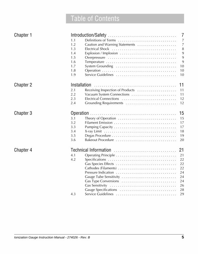
Table of Contents
Chapter 1 Introduction/Safety . . . . . . . . . . . . . . . . . . . . . . . . . . . . . . . . . . . 71.1 Definitions of Terms . . . . . . . . . . . . . . . . . . . . . . . . . . . . . . 71.2 Caution and Warning Statements . . . . . . . . . . . . . . . . . . . . 71.3 Electrical Shock . . . . . . . . . . . . . . . . . . . . . . . . . . . . . . . . . 81.4 Explosion / Implosion . . . . . . . . . . . . . . . . . . . . . . . . . . . . . 91.5 Overpressure . . . . . . . . . . . . . . . . . . . . . . . . . . . . . . . . . . . 91.6 Temperature . . . . . . . . . . . . . . . . . . . . . . . . . . . . . . . . . . . . 91.7 System Grounding . . . . . . . . . . . . . . . . . . . . . . . . . . . . . . . 101.8 Operation . . . . . . . . . . . . . . . . . . . . . . . . . . . . . . . . . . . . . . 101.9 Service Guidelines . . . . . . . . . . . . . . . . . . . . . . . . . . . . . . . 10
Chapter 2 Installation . . . . . . . . . . . . . . . . . . . . . . . . . . . . . . . . . . . . . . . . . . 112.1 Receiving Inspection of Products . . . . . . . . . . . . . . . . . . . . 112.2 Vacuum System Connections . . . . . . . . . . . . . . . . . . . . . . . 112.3 Electrical Connections . . . . . . . . . . . . . . . . . . . . . . . . . . . . 122.4 Grounding Requirements . . . . . . . . . . . . . . . . . . . . . . . . . . 12
Chapter 3 Operation . . . . . . . . . . . . . . . . . . . . . . . . . . . . . . . . . . . . . . . . . . . . 153.1 Theory of Operation . . . . . . . . . . . . . . . . . . . . . . . . . . . . . . 153.2 Filament Emission . . . . . . . . . . . . . . . . . . . . . . . . . . . . . . . . 173.3 Pumping Capacity . . . . . . . . . . . . . . . . . . . . . . . . . . . . . . . . 173.4 X-ray Limit . . . . . . . . . . . . . . . . . . . . . . . . . . . . . . . . . . . . . 183.5 Degas Procedure . . . . . . . . . . . . . . . . . . . . . . . . . . . . . . . . . 193.6 Bakeout Procedure . . . . . . . . . . . . . . . . . . . . . . . . . . . . . . . 20
Chapter 4 Technical Information . . . . . . . . . . . . . . . . . . . . . . . . . . . . . . . . 214.1 Operating Principle . . . . . . . . . . . . . . . . . . . . . . . . . . . . . . . 214.2 Specifications . . . . . . . . . . . . . . . . . . . . . . . . . . . . . . . . . . . 22
Gas Species Effects . . . . . . . . . . . . . . . . . . . . . . . . . . . . . . . 22Cathodes (Filaments) . . . . . . . . . . . . . . . . . . . . . . . . . . . . . . 22Pressure Indication . . . . . . . . . . . . . . . . . . . . . . . . . . . . . . . 24Gauge Tube Sensitivity . . . . . . . . . . . . . . . . . . . . . . . . . . . . 24Gas Type Conversions . . . . . . . . . . . . . . . . . . . . . . . . . . . . 24Gas Sensitivity . . . . . . . . . . . . . . . . . . . . . . . . . . . . . . . . . . 26Gauge Specifications . . . . . . . . . . . . . . . . . . . . . . . . . . . . . 28
4.3 Service Guidelines . . . . . . . . . . . . . . . . . . . . . . . . . . . . . . . 29

6 Ionization Gauge Instruction Manual - 274026 - Rev. B
Ionization Gauge Instruction Manual - 274026 - Rev. B 7
OperationTroubleshooting
SpecificationsIntroduction/Safety
Chapter 1 Introduction/Safety
For personal and equipment safety, all safety notices, cautions, and warnings must the adhered to at all times when working on or around a vacuum system, whether or not the system is in actual use. Follow all safety instructions provided throughout this instruction manual, and all safety practices recommended by your company.
NOTE: These instructions do not and cannot provide for every contingency that may arise in connection with the installation, operation, or maintenance of this product. If you require further assistance, contact Granville-Phillips Customer Support at the address on the title page, or page 10 of this instruction manual.
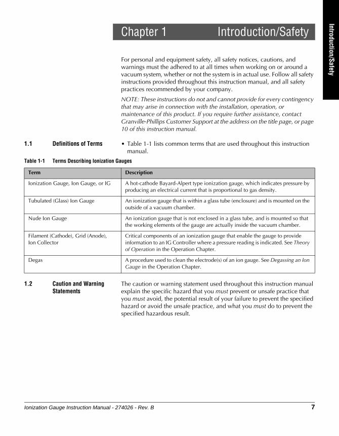
1.1 Definitions of Terms • Table 1-1 lists common terms that are used throughout this instruction manual.
1.2 Caution and Warning Statements
The caution or warning statement used throughout this instruction manual explain the specific hazard that you must prevent or unsafe practice that you must avoid, the potential result of your failure to prevent the specified hazard or avoid the unsafe practice, and what you must do to prevent the specified hazardous result.
Table 1-1 Terms Describing Ionization Gauges
Term Description
Ionization Gauge, Ion Gauge, or IG A hot-cathode Bayard-Alpert type ionization gauge, which indicates pressure by producing an electrical current that is proportional to gas density.
Tubulated (Glass) Ion Gauge An ionization gauge that is within a glass tube (enclosure) and is mounted on the outside of a vacuum chamber.
Nude Ion Gauge An ionization gauge that is not enclosed in a glass tube, and is mounted so that the working elements of the gauge are actually inside the vacuum chamber.
Filament (Cathode), Grid (Anode), Ion Collector
Critical components of an ionization gauge that enable the gauge to provide information to an IG Controller where a pressure reading is indicated. See Theory of Operation in the Operation Chapter.
Degas A procedure used to clean the electrode(s) of an ion gauge. See Degassing an Ion Gauge in the Operation Chapter.
Chapter 1
8 Ionization Gauge Instruction Manual - 274026 - Rev. B
1.3 Electrical Shock
Do NOT touch any gauge electronics while the gauge is connected to the controller. During normal operation, 180 volts will be applied to the grid connections. During electron bombardment degas, as much as 700 volts may be applied to some electrode pins.
All connections to the gauge tube should be covered by insulation. All gauge tube pins should be covered by connectors or by pin covers.
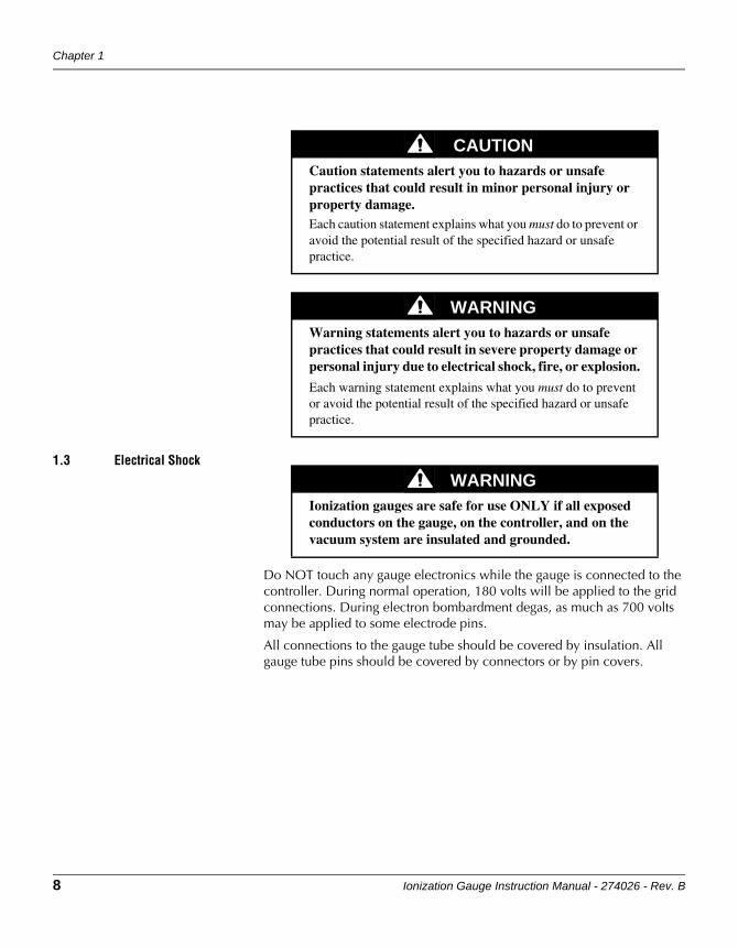
CAUTIONCaution statements alert you to hazards or unsafe practices that could result in minor personal injury or property damage.Each caution statement explains what you must do to prevent or avoid the potential result of the specified hazard or unsafe practice.
WARNINGWarning statements alert you to hazards or unsafe practices that could result in severe property damage or personal injury due to electrical shock, fire, or explosion.
Each warning statement explains what you must do to prevent or avoid the potential result of the specified hazard or unsafe practice.
WARNINGIonization gauges are safe for use ONLY if all exposed conductors on the gauge, on the controller, and on the vacuum system are insulated and grounded.
Introduction/Safety
Ionization Gauge Instruction Manual - 274026 - Rev. B 9
OperationTroubleshooting
SpecificationsIntroduction/Safety
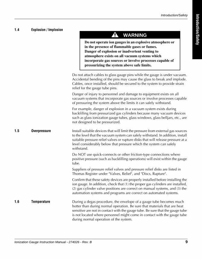
1.4 Explosion / Implosion
Do not attach cables to glass gauge pins while the gauge is under vacuum. Accidental bending of the pins may cause the glass to break and implode. Cables, once installed, should be secured to the system to provide strain relief for the gauge tube pins.
Danger of injury to personnel and damage to equipment exists on all vacuum systems that incorporate gas sources or involve processes capable of pressuring the system above the limits it can safely withstand.
For example, danger of explosion in a vacuum system exists during backfilling from pressurized gas cylinders because many vacuum devices such as glass ionization gauge tubes, glass windows, glass belljars, etc., are not designed to be pressurized.
1.5 Overpressure Install suitable devices that will limit the pressure from external gas sources to the level that the vacuum system can safely withstand. In addition, install suitable pressure relief valves or rupture disks that will release pressure at a level considerably below that pressure which the system can safely withstand.
Do NOT use quick-connects or other friction-type connections where positive pressure (such as backfilling operations) will exist within the gauge tube.
Suppliers of pressure relief valves and pressure relief disks are listed in Thomas Register under "Valves, Relief", and "Discs, Rupture".
Confirm that these safety devices are properly installed before installing the ion gauge. In addition, check that (1) the proper gas cylinders are installed, (2) gas cylinder valve positions are correct on manual systems, and (3) the automation systems and programs are correct on automated systems.
1.6 Temperature During a degas procedure, the envelope of a gauge tube becomes much hotter than during normal operation. Be sure that materials that are heat sensitive are not in contact with the gauge tube. Be sure that the gauge tube is not located where personnel might come in contact with the gauge tube during normal operation of the system.
WARNINGDo not operate ion gauges in an explosive atmosphere or in the presence of flammable gases or fumes. Danger of explosion or inadvertent venting to atmosphere exists on all vacuum systems which incorporate gas sources or involve processes capable of pressurizing the system above safe limits.
Chapter 1
10 Ionization Gauge Instruction Manual - 274026 - Rev. B
1.7 System Grounding Grounding, though simple, is very important! Be certain that ground circuits are correctly used on your ion gauge power supplies, gauges, and vacuum chambers, regardless of their manufacturer. Safe operation of vacuum equipment requires grounding of all exposed conductors of the gauges, the controller and the vacuum system. Lethal Voltages may be established under some operating conditions unless correct grounding is provided.
Ion producing equipment, such as ionization gauges, mass spectrometers, sputtering systems, etc., from many manufacturers may, under some conditions, provide sufficient electrical conduction via a plasma to couple a high voltage electrode potential to the vacuum chamber. If exposed conductive parts of the gauge, controller, and chamber are not properly grounded, they may attain a potential near that of the high voltage electrode during this coupling. Fatal electrical shock could then occur because of the high voltage between these exposed conductors and ground.
1.8 Operation It is the installer's responsibility to ensure that the automatic signals provided by the process control module are always used in a safe manner.
Carefully check manual operation of the system and the setpoint programming before switching to automatic operation. Where an equipment malfunction could cause a hazardous situation, always provide for fail-safe operation. As an example, in an automatic backfill operation where a malfunction might cause high internal pressures, provide an appropriate pressure relief device.
1.9 Service Guidelines For customer service:
If the product requires service, contact the MKS, Granville-Phillips Division Customer Service Department at +1-800-227-8766 or +1-303-652-4691 for troubleshooting help over the phone.
For Customer Service or Technical Support 24 hours per day, 7 days per week, every day of the year including holidays:
Phone: +1-800-227-8766 or +1-303-652-4691
Email:[email protected]
MKS, Granville-Phillips Division
6450 Dry Creek Parkway
Longmont, CO 80503 USA
Phone: 1-303-652-4691 or 1-800-776-6543
FAX: 1-303-652-2844
Ionization Gauge Instruction Manual - 274026 - Rev. B 11
Installation
Chapter 2 Installation
Before installing a Series 274 Bayard-Alpert (B-A) gauge on your vacuum system, be sure you understand and follow the Cautions, Warnings, and guidelines presented in the Introduction/Safety Chapter of this Instruction Manual.
If you are replacing an existing gauge, Figure 2-1 lists B-A style gauges that are equivalent to the Series 274 B-A gauges. Check the catalog number of the gauge being installed to be sure you have a direct match.
2.1 Receiving Inspection of Products
Thoroughly inspect the product(s) to be sure you have received the product(s) you ordered, and that no shipping damage has occurred. For missing or shipping damaged items, contact the carrier that made the delivery. If you have any questions regarding the product(s), contact Granville Phillips Customer Service; see Service Guidelines on page 10.
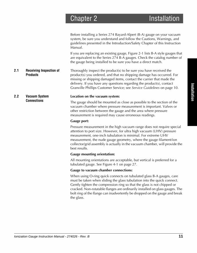
2.2 Vacuum System Connections
Location on the vacuum system:
The gauge should be mounted as close as possible to the section of the vacuum chamber where pressure measurement is important. Valves or other restriction between the gauge and the area where pressure measurement is required may cause erroneous readings.
Gauge port:
Pressure measurement in the high vacuum range does not require special attention to port size. However, for ultra high vacuum (UHV) pressure measurement, one-inch tubulation is minimal. For extreme UHV measurement, the nude gauge geometry, where the gauge filament/ion collector/grid assembly is actually in the vacuum chamber, will provide the best results.
Gauge mounting orientation:
All mounting orientations are acceptable, but vertical is preferred for a tubulated gauge. See Figure 4-1 on page 27.
Gauge to vacuum chamber connections:
When using O-ring quick connects on tubulated glass B-A gauges, care must be taken when sliding the glass tubulation into the quick connect. Gently tighten the compression ring so that the glass is not chipped or cracked. Non-rotatable flanges are ordinarily installed on glass gauges. The bolt ring of the flange can inadvertently be dropped on the gauge and break the glass.
12 Ionization Gauge Instruction Manual - 274026 - Rev. B
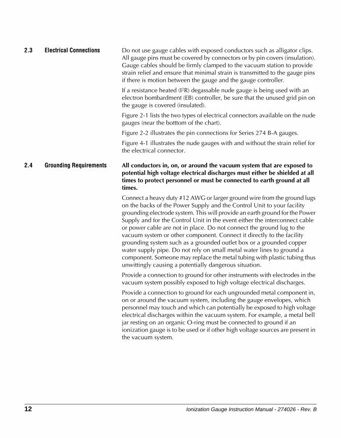
2.3 Electrical Connections Do not use gauge cables with exposed conductors such as alligator clips. All gauge pins must be covered by connectors or by pin covers (insulation). Gauge cables should be firmly clamped to the vacuum station to provide strain relief and ensure that minimal strain is transmitted to the gauge pins if there is motion between the gauge and the gauge controller.
If a resistance heated (I2R) degassable nude gauge is being used with an electron bombardment (EB) controller, be sure that the unused grid pin on the gauge is covered (insulated).
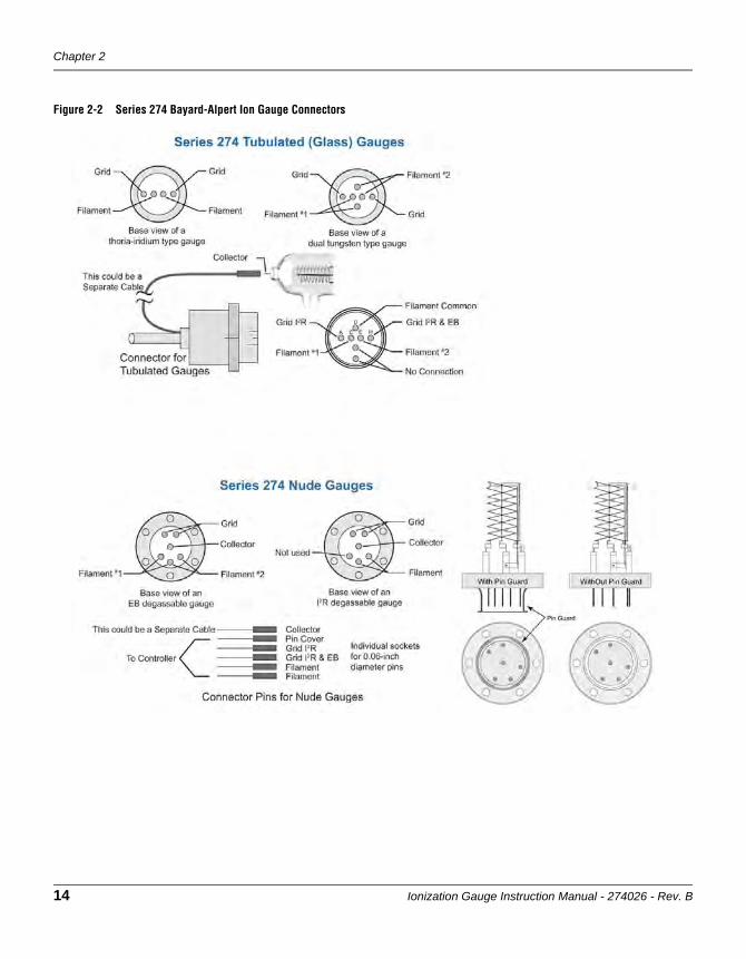
Figure 2-1 lists the two types of electrical connectors available on the nude gauges (near the botttom of the chart).
Figure 2-2 illustrates the pin connections for Series 274 B-A gauges.
Figure 4-1 illustrates the nude gauges with and without the strain relief for the electrical connector.
2.4 Grounding Requirements All conductors in, on, or around the vacuum system that are exposed to potential high voltage electrical discharges must either be shielded at all times to protect personnel or must be connected to earth ground at all times.
Connect a heavy duty #12 AWG or larger ground wire from the ground lugs on the backs of the Power Supply and the Control Unit to your facility grounding electrode system. This will provide an earth ground for the Power Supply and for the Control Unit in the event either the interconnect cable or power cable are not in place. Do not connect the ground lug to the vacuum system or other component. Connect it directly to the facility grounding system such as a grounded outlet box or a grounded copper water supply pipe. Do not rely on small metal water lines to ground a component. Someone may replace the metal tubing with plastic tubing thus unwittingly causing a potentially dangerous situation.
Provide a connection to ground for other instruments with electrodes in the vacuum system possibly exposed to high voltage electrical discharges.
Provide a connection to ground for each ungrounded metal component in, on or around the vacuum system, including the gauge envelopes, which personnel may touch and which can potentially be exposed to high voltage electrical discharges within the vacuum system. For example, a metal bell jar resting on an organic O-ring must be connected to ground if an ionization gauge is to be used or if other high voltage sources are present in the vacuum system.

Installation
Ionization Gauge Instruction Manual - 274026 - Rev. B 13
Installation
Figure 2-1 Bayard-Alpert Ion Gauge Equivalent List
* Notes: * Granville-Phillips Series 274 Nude Gauges are electrically equivalent to other manufacturers, but the pin
geometry may be different.* Granville-Phillips Nude Gauges, catalog numbers 274022, 274023, 274028, and 274050 do not have a
strain relief for the electrical connector. See Figure 4-1.* Granville-Phillips Nude Gauges, catalog numbers 274041, 274042, 274043 have a locking strain relief
connector. See Figure 4-1.
Chapter 2
14 Ionization Gauge Instruction Manual - 274026 - Rev. B
Figure 2-2 Series 274 Bayard-Alpert Ion Gauge Connectors

Ionization Gauge Instruction Manual - 274026 - Rev. B 15
TroubleshootingSpecifications
IntroductionOperation
Chapter 3 Operation
This chapter explains the basic operating principles of a Bayard-Alpert (B-A) ionization gauge, including:
• Theory of operation of B-A gauges
• Filament emission of B-A gauges
• Pumping capacity of B-A gauges
• X-ray limit of B-A gauges
• Degas procedure for B-A gauges
• Bakeout procedure for B-A gauges
3.1 Theory of Operation A Bayard-Alpert vacuum gauge ionizes the gas molecules within the gauge volume, collects those ions on a thin ion collector wire, and measures the resulting current to the ion collector to determine the number of molecules present and indicates a pressure based on that measurement.
A B-A gauge is a hot-filament style ionization gauge. It is called such because a heated filament (cathode) is used to emit electrons toward a grid (anode). See Figure 3-1.
The pressure indication of a B-A vacuum gauge is based on the ionization of the gas molecules by a constant flow of electrons. The negative electrons are emitted at a well-controlled, selectable rate from a heated filament (cathode) and are accelerated toward a positively-charged wire grid (anode). Electrons pass into the space enclosed by the grid. In this space the electrons collide with the gas molecules that are in the vacuum system, and produce positive ions. The positive ions are then collected by the ion collector that is located along the axis of the cylindrical grid. The ion collector is at nearly ground potential, which is negative with respect to the grid. At a constant filament-to-grid voltage and electron emission current, the rate that positive ions are formed is directly proportional to the density of molecules (pressure) in the gauge for pressures below approximately 1 x 10⁻³ Torr. The strength of the ion current is then indicated on an electrometer that is calibrated in units of pressure.
Because the pressure indication is linear, the hot cathode B-A gauge is generally considered to be the most accurate continuous indicator for pressures below 1 x 10⁻³ Torr.
Chapter 3
16 Ionization Gauge Instruction Manual - 274026 - Rev. B
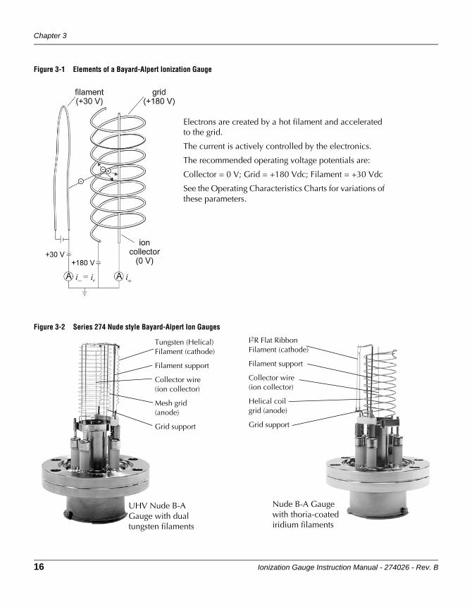
Figure 3-1 Elements of a Bayard-Alpert Ionization Gauge
Figure 3-2 Series 274 Nude style Bayard-Alpert Ion Gauges
Electrons are created by a hot filament and accelerated to the grid.
The current is actively controlled by the electronics.
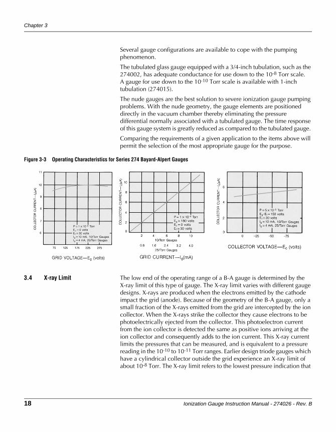
The recommended operating voltage potentials are:
Collector = 0 V; Grid = +180 Vdc; Filament = +30 Vdc
See the Operating Characteristics Charts for variations of these parameters.
Tungsten (Helical)Filament (cathode)
Filament support
Collector wire(ion collector)
Mesh grid(anode)
Grid support
I2R Flat RibbonFilament (cathode)
Filament support
Collector wire(ion collector)
Helical coilgrid (anode)
Grid support
UHV Nude B-AGauge with dualtungsten filaments
Nude B-A Gaugewith thoria-coatediridium filaments
Operation
Ionization Gauge Instruction Manual - 274026 - Rev. B 17
OperationSpecifications
IntroductionOperation
3.2 Filament Emission There are two types of materials commonly used for filaments: tungsten or thoria-coated iridium. The most common style is coated iridium because they operate at a lower temperature than tungsten, therefore less reactive. Coated iridium filaments are also more burnout resistant when exposed to atmospheric pressure while power is on. Tungsten filaments will burn out immediately if exposed to pressures of 1 x 10⁻² Torr or higher while they're on. However, tungsten filaments are the best type to use when the chemistry (such as halogen compounds) of the vacuum process causes premature failure of coated iridium filaments.
The amount of emission current that a B-A gauge requires for proper operation depends on many factors such as: the size or style of the gauge, the process in which the gauge is used, the pressure range of operation, and the desired accuracy of the indicated pressure. Emission currents are typically in the range of 25 µA to 10 mA.
Generally, low emission current is used in the high pressure end of the range of a B-A gauge, which helps avoid the ion turn-around phenomenon and glow discharge. High emission current is used at ultra high vacuum to obtain ion currents large enough for convenient measurement. Typical values are 100 µA at 10-3 Torr and 10 mA at 10-9 Torr. The trade-offs on emission current are that high emission current gives better readout stability and sensitivity, but more pumping if the gauge is clean, and more outgassing if the gauge is contaminated. Likewise, low emission currents minimize gauge outgassing and minimize pumping. However, low emission currents yield low ion currents which are sensitive to electronic noise and may be too low for a given electrometer to measure.
3.3 Pumping Capacity The ionization gauge exhibits a certain pumping capacity. This is due to both chemical and electrical effects. Chemical pumping is due, in general, to the affinity of gases for very clean surfaces. As the surface becomes saturated, the pumping action is diminished and reaches a steady state value. Readings for a typical glass- tabulated gauge will be 20 to 50 percent lower during the period of chemical pumping. The duration of the pumping may be of the order of four hours at I x 10-9 Torr. Electronic, or ionic pumping saturates after pumping approximately three months at I x 10-9 Torr. The most common remedy for pumping effects is to provide a passage of large conductance between the gauge and the vacuum system.
A third mechanism of pumping in gauges involves chemical reactions with the hot cathode. A number of gases such as oxygen, nitrogen, water vapor, and hydrogen have been shown to react with the carbon present in tungsten. The ratio of these reactions are dependent on the cathode temperature, and are low enough that serious errors in measurement can be avoided when high-conductance connections are used. In small systems, however, the change in gas composition may be significant.
Chapter 3
18 Ionization Gauge Instruction Manual - 274026 - Rev. B
Several gauge configurations are available to cope with the pumping phenomenon.
The tubulated glass gauge equipped with a 3/4-inch tubulation, such as the 274002, has adequate conductance for use down to the 10-8 Torr scale.A gauge for use down to the 10-10 Torr scale is available with 1-inch tubulation (274015).
The nude gauges are the best solution to severe ionization gauge pumping problems. With the nude geometry, the gauge elements are positioned directly in the vacuum chamber thereby eliminating the pressure differential normally associated with a tubulated gauge. The time response of this gauge system is greatly reduced as compared to the tubulated gauge.
Comparing the requirements of a given application to the items above will permit the selection of the most appropriate gauge for the purpose.
Figure 3-3 Operating Characteristics for Series 274 Bayard-Alpert Gauges
3.4 X-ray Limit The low end of the operating range of a B-A gauge is determined by the X-ray limit of this type of gauge. The X-ray limit varies with different gauge designs. X-rays are produced when the electrons emitted by the cathode impact the grid (anode). Because of the geometry of the B-A gauge, only a small fraction of the X-rays emitted from the grid are intercepted by the ion collector. When the X-rays strike the collector they cause electrons to be photoelectrically ejected from the collector. This photoelectron current from the ion collector is detected the same as positive ions arriving at the ion collector and consequently adds to the ion current. This X-ray current limits the pressures that can be measured, and is equivalent to a pressure reading in the 10-10 to 10-11 Torr ranges. Earlier design triode gauges which have a cylindrical collector outside the grid experience an X-ray limit of about 10-8 Torr. The X-ray limit refers to the lowest pressure indication that
Operation
Ionization Gauge Instruction Manual - 274026 - Rev. B 19
OperationSpecifications
IntroductionOperation
may be obtained in a gauge when all the output current is due to X-ray induced photo emission and there is an absence of gas.
The X-ray limit of standard glass or nude B-A gauges is approximately 3x10⁻¹⁰ Torr. To measure below this limit, an ultrahigh vacuum (UHV) nude B-A gauge can be used. The UHV nude gauge has an X-ray limit of approximately 2x10-11 Torr. This lower X-ray limit is achieved by modifying two elements of the standard B-A gauge design. First, the diameter of the collector is reduced. The smaller cross-sectional area reduces the probability that the X-rays created at the grid will strike the collector. Second, the helical grid structure is replaced with a fine-wire mesh grid structure, and there is also a fine-wire structure across both ends of the grid. The fine grid wires provide a more transparent grid for longer electron path lengths, and the grid ends confine the positive ions for better ion collection. Together, these two modifications cause a higher gauge sensitivity for ions from the gas phase which causes the X-ray current to be converted into a smaller pressure indication (i.e., a lower X-ray limit).
Some processes can result in deposits on the electrodes. These deposits can lead to an increase in X-ray limit since more electrons are released under X-ray bombardment. Process deposits can generally be removed by degassing the electrodes.
3.5 Degas Procedure The deposition of elements or compounds on exposed gauge surfaces can result from some processes, such as sputtering or coating operations. Water vapor is another compound that can collect inside the gauge when a vacuum chamber is exposed to atmosphere. During normal operation these materials will slowly come off the gauge surfaces, increasing the local pressure in the gauge. To more rapidly get the pressure in the gauge in equilibrium with the pressure in the chamber, "degassing" can be used to drive the molecules on the inner walls and surfaces from the gauge back into the chamber where they can be pumped out of the system. Degassing can be done as required or as part of a regular pumpdown sequence. Regular degassing helps prevent process deposits from collecting and allows the gauge to provide lower and more repeatable pressure indications by bringing the pressure in the gauge closer to equilibrium with the chamber.
There are two types of degassing techniques: Electron Bombardment (EB) and Resistive (I2R). EB degas must be used for UHV nude gauges with fine wire mesh grids and can also be used for glass or nude gauges with helical coil grids. I2R degas can only be used for gauges with helical grids.
Although similar in result, each degassing technique employs a different mechanism to perform this beneficial function.
• EB degassing is accomplished by increasing the anode voltage and the emission current to bombard the gauge with electrons of sufficient quantity and energy to displace deposited molecules. EB degassing is
Chapter 3
20 Ionization Gauge Instruction Manual - 274026 - Rev. B
preferable at ultra-high vacuum.
• I2R degassing is accomplished by passing current through the grid (anode) at a sufficient level to raise the grid temperature to displace the molecules. I2R degassing requires longer degassing periods, and is preferable to perform only at pressures below 10-5 Torr. Only a few minutes is required at pressures above 10-6 Torr. If a system is used in the UHV range, degas in the 10-6 Torr range, then again at the UHV operating pressure.
Use ONLY the EB degas mode for the EB degassable nude gauges 274022, 274023, 274041, 274042, 274050, 274057, and 274058. See the NUDE gauges listed in Figure 2-1.
Tubulated glass gauges and nude gauges 274028 and 274043 can be degassed using either the EB or I2R mode. See the NUDE gauges listed in Figure 2-1.
Cleaning a gauge with solvents is not recommended. However, if a gauge has been exposed to silicone-based pump oil, solvent may be needed to remove the oil. If solvent is used, the gauge must be thoroughly dried before installing it back on the system and operating or degassing it.
3.6 Bakeout Procedure Bakeout of a B-A gauge is necessary if the system is expected to pump down to an ultra-clean state. Do not bake glass B-A gauges over 450 oC because glass softening may occur above that temperature.

Ionization Gauge Instruction Manual - 274026 - Rev. B 21
OperationTroubleshooting
Technical Info/SpecsIntroduction
Chapter 4 Technical Information
4.1 Operating Principle The pressure indication of a hot cathode Bayard-Alpert (B-A) gauge is based on the ionization of gas molecules by a constant flow of electrons. The negative electrons are emitted at a well-controlled, selectable rate from a heated cathode and are accelerated toward a positively charged wire grid (anode). Electrons pass into the space between the grid and the collector wire. In this space the electrons collide with gas molecules from the vacuum system, producing positive ions. The positive ions are then collected by the ion collector wire which is at nearly ground potential, thus negative with respect to the grid and is located along the axis of the cylindrical grid. At a constant filament to grid voltage and electron emission current, the rate that positive ions are formed is directly proportional to the density of molecules (pressure) in the space for pressures below 1 x 10⁻³ Torr. The strength of the ion current is then indicated on a electrometer that is calibrated in units of pressure. Since as the pressure indication is linear, the hot cathode Bayard-Alpert gauge is generally considered the most accurate continuous indicator for pressures below 1 x 10⁻³ Torr.
More detailed information regarding the theory of operation for B-A gauges is presented in the Operation Chapter of this Instruction Manual.
The low end of the operating range of a B-A gauge is determined by the X-ray limit of this type of gauge. The X-ray limit varies with different gauge designs. X-rays are produced when the electrons emitted by the cathode impact the grid and support wires. Because of the geometry of the B-A gauge, only a small fraction of the emitted X-rays are intercepted by the ion collector. When the X-rays strike the collector wire they cause electrons to be photoelectrically ejected from the collector. This X-ray current limits the pressures that can be measured, and is equivalent to a pressure reading in the 10-11 Torr range. Earlier gauges that had a cylindrical collector outside the grid experienced an X-ray limit of about 10-8 Torr. The X-ray limit refers to the lowest pressure indication that may be obtained in a gauge when all the output current is due to X-ray induced photoemission and there is an absence of gas.
The X-ray limit will be increased as a result of hydrocarbon contamination of the electrodes, since contaminated surfaces release more secondary electrons under X-ray bombardment. Such contamination can generally be removed by thorough degassing of the electrodes
More detailed information regarding the X-ray limit of B-A gauges is presented in the Operation Chapter of this Instruction Manual.
22 Ionization Gauge Instruction Manual - 274026 - Rev. B
4.2 Specifications
Gas Species Effects Bayard-Alpert (B-A) ionization gauges have different relative sensitivities for different gas species. As a result, the pressure readout provides a direct reading only for the gas for which the gauge is specified (usually nitrogen). This is called a readout of nitrogen equivalent pressure. A simple mathematical conversion of the direct pressure readout to the pressure of the non standard gas can be made. This conversion is made using the relative gauge sensitivity for the specific gas. These sensitivities are in Table 4-3 on page 26.
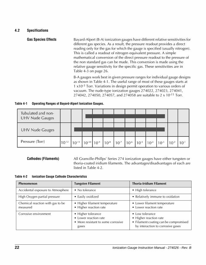
B-A gauges work best in given pressure ranges for individual gauge designs as shown in Table 4-1. The useful range of most of these gauges starts at1 x10-3 Torr. Variations in design permit operation to various orders of vacuum. The nude-type ionization gauges 274022, 274023, 274041, 274042, 274050, 274057, and 274058 are suitable to 2 x 10-11 Torr.
Table 4-1 Operating Ranges of Bayard-Alpert Ionization Gauges.
Cathodes (Filaments) All Granville-Phillps’ Series 274 ionization gauges have either tungsten or thoria-coated iridium filaments. The advantages/disadvantages of each are listed in Table 4-2.
Table 4-2 Ionization Gauge Cathode Characteristics
Phenomenon Tungsten Filament Thoria-Iridium Filament
Accidental exposure to Atmosphere • No tolerance • High tolerance
High Oxygen partial pressure • Easily oxidized • Relatively immune to oxidation
Chemical reaction with gas to be measured
• Higher filament temperature• Higher reaction rate
• Lower filament temperature• Lower reaction rate
Corrosive environment • Higher tolerance• Lower reaction rate• More resistant to some corrosive
gases
• Low tolerance• Higher reaction rate• Filament coating can be compromised
by interaction to corrosive gases
Technical Information
Ionization Gauge Instruction Manual - 274026 - Rev. B 23
OperationTroubleshooting
Technical Info/SpecsIntroduction
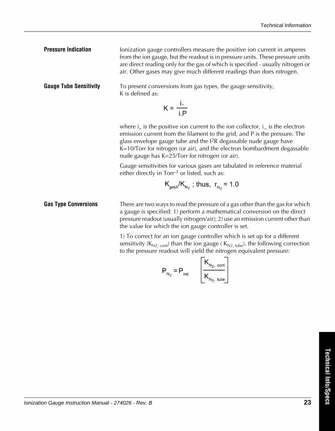
Pressure Indication Ionization gauge controllers measure the positive ion current in amperes from the ion gauge, but the readout is in pressure units. These pressure units are direct reading only for the gas of which is specified - usually nitrogen or air. Other gases may give much different readings than does nitrogen.
Gauge Tube Sensitivity To present conversions from gas types, the gauge sensitivity, K is defined as:
where i+ is the positive ion current to the ion collector, i_ is the electron emission current from the filament to the grid, and P is the pressure. The glass envelope gauge tube and the I2R degassable nude gauge have K=10/Torr for nitrogen (or air), and the electron bombardment degassable nude gauge has K=25/Torr for nitrogen (or air).
Gauge sensitivities for various gases are tabulated in reference material either directly in Torr-1 or listed, such as:
Gas Type Conversions There are two ways to read the pressure of a gas other than the gas for which a gauge is specified: 1) perform a mathematical conversion on the direct pressure readout (usually nitrogen/air); 2) use an emission current other than the value for which the ion gauge controller is set.
1) To correct for an ion gauge controller which is set up for a different sensitivity (KN2, cont) than the ion gauge ( KN2, tube), the following correction to the pressure readout will yield the nitrogen equivalent pressure:

Chapter 4
24 Ionization Gauge Instruction Manual - 274026 - Rev. B
To convert the readout to a different gas, the equation must also include KgasX, tube
2) Most ion gauge controllers are designed for some calibrated set-point of emission = i_. The emission that corrects for both controller sensitivity and gas type is:
Technical Information
Ionization Gauge Instruction Manual - 274026 - Rev. B 25
OperationTroubleshooting
Technical Info/SpecsIntroduction
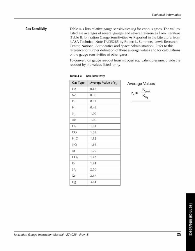
Gas Sensitivity Table 4-3 lists relative gauge sensitivities (rX) for various gases. The values listed are averages of several gauges and several references from literature (Table II, Ionization Gauge Sensitivities As Reported in the Literature, from NASA Technical Note TND5285 by Robert L. Summers, Lewis Research Center, National Aeronautics and Space Administration). Refer to this reference for further definition of these average values and for calculations of the gauge sensitivities of other gases.
To convert ion gauge readout from nitrogen equivalent pressure, divide the readout by the values listed for rx..
Table 4-3 Gas Sensitivity
Gas Type Average Value of rX
He 0.18
Ne 0.30
D2 0.35
H2 0.46
N2 1.00
Air 1.00
O2 1.01
CO 1.05
H2O 1.12
NO 1.16
Ar 1.29
CO2 1.42
Kr 1.94
SF6 2.50
Xe 2.87
Hg 3.64
Chapter 4
26 Ionization Gauge Instruction Manual - 274026 - Rev. B
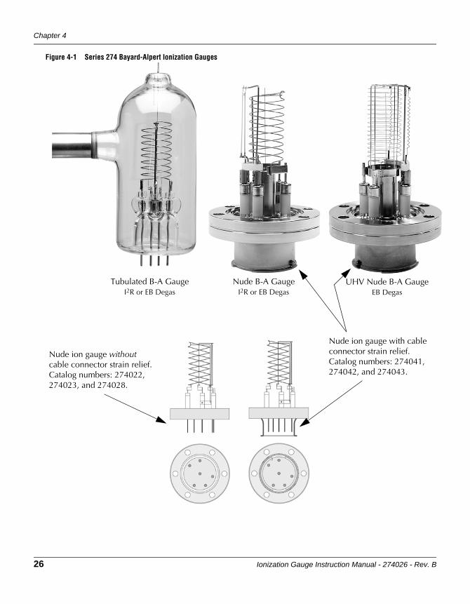
Figure 4-1 Series 274 Bayard-Alpert Ionization Gauges
UHV Nude B-A GaugeEB Degas
Nude B-A GaugeI2R or EB Degas
Tubulated B-A GaugeI2R or EB Degas
Nude ion gauge without cable connector strain relief. Catalog numbers: 274022, 274023, and 274028.
Nude ion gauge with cable connector strain relief. Catalog numbers: 274041, 274042, and 274043.

Technical Information
Ionization Gauge Instruction Manual - 274026 - Rev. B 27
OperationTroubleshooting
Technical Info/SpecsIntroduction
Gauge Specifications
Table 4-4 Series 274 Bayard-Alpert Gauge Physical and Operating Data
Physical Data Tubulated Gauge EB Degassable Nude Gauge I2R Degassable Nude Gauge
Tubulation .75 inch (19mm) or 1 inch (25mm) dia. x 2.25 inch (57mm ) long, Kovar, Pyrex, or flanged
N.A. N.A.
Envelope Nonex 7720 Glass, 2.25 inch (57mm) dia. x 5 inch (127mm) long
Nude with 2.75 inch o.d. ConFlat flange
Nude with 2.75 inch o.d. ConFlat flange
Mounting Position Any - Vertical preferred Any Any
Collector Tungsten, .010 inch dia. Tungsten, .005 inch dia. Tungsten, .010 inch dia.
Cathode Dual tungsten or one thoria coated Iridium
Dual tungsten or dual thoria coated Iridium on replaceable assembly
Thoria coated iridium on replaceable assembly
Grid Refractory metals Refractory metals Refractory metals
Overall Length 6 inch (152mm) 4.125 inch (105mm) 4.125 inch (105mm)
Insertion Length N.A. 3 inch (76mm) 3 inch (76mm)
Operating Data Tubulated Gauge EB Degassable Nude Gauge I2R Degassable Nude Gauge
Sensitivity for N2 10/Torr 25/Torr 10/Torr
Typical Accuracy ± 20% ± 20% ± 20%
X-ray Limit About 3 x 10⁻¹⁰ About 2 x 10-11 About 4 x 10⁻¹⁰
EB Degas 100 watts max. 40 watts max. 100 watts max., 70 watts nominal
I2R Degas 6.3 to 7.5 VAC at 10 A N.A. 6.3 to 7.5 VAC at 10 A
Bakeout 450 oC 450 oC 450 oC
Cathode Heating Current 4 to 6 A 2.5 to 3.5 A 4 to 6 A
Cathode Heating Voltage 3 to 5 V 3 to 5 V 3 to 5 V
Cathode Heating Potential +30 Vdc +30 Vdc +30 Vdc
Collector Potential 0 V 0 V 0 V
Grid Potential +180 Vdc +180 Vdc +180 Vdc
EB = Electron Bombardment Degas / I2R = Resistance Heated Degas / N2 = Nitrogen / N.A. = Not Applicable
Chapter 4
28 Ionization Gauge Instruction Manual - 274026 - Rev. B
4.3 Service Guidelines For customer service:
If the product requires service, contact the MKS, Granville-Phillips Division Customer Service Department at +1-800-227-8766 or +1-303-652-4691 for troubleshooting help over the phone.
If the product must be returned to the factory for service, request a Return Material Authorization (RMA) from Granville-Phillips. Do not return products without first obtaining an RMA. In some cases a hazardous materials document may be required. The MKS/Granville-Phillips Customer Service Representative will advise you if the hazardous materials document is required.
When returning a products to Granville-Phillips, be sure to package the products to prevent shipping damage. Circuit boards and modules separated from the gauge assembly must be handled using proper anti-static protection methods and must be packaged in anti-static packaging. Granville-Phillips will supply return packaging materials at no charge upon request. Shipping damage on returned products as a result of inadequate packaging is the Buyer's responsibility.
For Customer Service or Technical Support 24 hours per day, 7 days per week, every day of the year including holidays:
Phone: +1-800-227-8766 or +1-303-652-4691
Email: [email protected]
MKS, Granville-Phillips Division
6450 Dry Creek Parkway
Longmont, CO 80503 USA
Phone: 1-303-652-4691 or 1-800-776-6543
FAX: 1-303-652-2844

Instruction Manual part number 274026
Revision B - August 2014

Instruction Manual part number 274026
Revision B - August 2014
Series 274
Granville-Phillips® Series 274 Bayard-Alpert Type Ionization Gauges
Instruction Manual
For Customer Service or Technical Support 24 hours per day, 7 days per week, every day of the year including holidays:Phone: +1-800-227-8766 or +1-303-652-4691
MKS, Granville-Phillips Division6450 Dry Creek ParkwayLongmont, CO 80503 USA
Phone: 1-303-652-4691 or 1-800-776-6543 FAX: 1-303-652-2844Email: [email protected]
Corporate OfficeMKS Instruments, Inc.2 Tech Drive, Suite 201Andover, MA 01810 USA
Phone: 1-978-645-5500www.mksinst.com