GRAFTON SCIENCE PARK - Tufts University
25
GRAFTON SCIENCE PARK Master Plan / Design Requirements and Review Criteria JM Holdings Corporation (Holdings) Jean Mayer Administration Building, Room 222 200 Westboro Road North Grafton, Massachusetts 01536-1895 July 2016
Transcript of GRAFTON SCIENCE PARK - Tufts University

G R A F TO N S C I E N C E PA R K
Master Plan / Design Requirements and Review Criteria
JM Holdings Corporation (Holdings)
Jean Mayer Administration Building, Room 222200 Westboro RoadNorth Grafton, Massachusetts 01536-1895
July 2016

1
Requirements and Review Criteria
TABLE OF CONTENTS
1. INTRODUCTION1.1 Statement of Intent1.2 Overall Design Policies
2. DESIGN REVIEW/PLANNING OVERVIEW2.1 Membership of Science Park Design Review Board 2.2 Design Review Process2.2.1 Concept Plan and Schematic Design Submittal (for Individual Projects)2.2.2 DesignDevelopmentPlansandSpecificationsSubmittal2.2.3 FinalPlansandSpecificationsSubmittal
3. DEVELOPMENT LAND USE AND DEVELOPMENT INTENSITY
4. BUILDING DESIGN4.1 Overall Approach4.2 Sustainable Development4.3 Building Locations and Envelopes4.4 Building Massing4.5 Building Height4.6 Building Materials and Palette4.7 Environmental Mitigation Measures
5. SITE DESIGN5.1 Layout and Grading of Development5.2 Dimensional Requirements for Roads and Walkways5.3 Service Areas5.4 Drainage and Erosion Control5.5 Materials for Hardscape5.6 Parking Requirements
6. LIGHTING 6.1 Pedestrian Walkways6.2 Building Exterior6.3 Parking Lots and Service Areas6.4 Roadways and Intersections
7. SIGNAGE7.1 Signs at Entrance7.2 Signs on Building Exteriors

2
8. PLANTING8.1 Intent8.2 Design Guidelines and Criteria for Planting8.2.1 Tree Preservation and Protection8.2.2 New Planting8.2.3 Area A: New Planting for Roads and Driveways8.2.4 Area B: New Planting for Parking Lots8.2.5 Area C: New Planting for Building Edges and Entrances8.2.6 Area D: New Planting for Service Areas8.2.7 Area E: New Planting for Edges of Development Abutting Natural Areas8.3 Plant Lists8.3.1 Area A: Plant List for Roads and Driveways8.3.2 Area B: Plant List for Parking Lots8.3.3 Area C: Plant List for Building Edges and Entrances8.3.4 Area D: Plant List for Service Areas8.3.5 Area E: Plant List for Edges of Development Abutting Natural Areas
AttachmentsSpagnolo/Gisness Associates’ Plans are provided for illustrative purposes. Figure A1: Spagnolo, Gisness Conceptual Plan (September 2005)Figure A2: Site Sections A-C (September 2005)Figure A3: Site Planting Areas Plan (September 2005)Figure A4: Representative Parking Layout

3
1. Introduction
1.1 Statement of Intent The design and development requirements and criteria described in this document have been written to guide future devel-opment of the Grafton Science Park. Their intent is to facilitate and expedite development by establishing clear expectations, while mitigating the effects of development on the 84-acre site, by respecting its environmental constraints, maintaining its distinctive rural character, and complementing the historic characteristics of the campus.
1.2 Overall Design Policies Accordingly, the overall Development Plan for Grafton Science Park should reflect the following overall design policies:
• Minimize Impacts on Natural Features and Site Character. Locate and design proposed buildings to respect the natural terrain.Mature stands of trees should be preserved if possible. Minimize site disturbance and earthworks. Proposed grading should follow existing grades to the maximum extent practicable. Use underground utilities and screen the necessary aboveground utilities and appurtenances.
• Architectural Continuity with the Adjacent Cummings School CampusDesign buildings to reflect the character, color, and texture of the historic buildings on the Grafton campus.
• Avoid Impacts to Sensitive Environmental Resource AreasLocate and design the development to avoid impacts on the bordering vegetative wetlands.
• Manage Traffic Encourage pedestrian access and the use of the nearby commuter rail station. Keep roadway widths, turning radii and intersections as small as possible to discourage speeding. Create parking lots with trees and internal landscaped islands to reduce their scale. Segregate truck access and service areas to the greatest extent possible. Provide amenities that encourage bicycle use.
• Wayfinding and SafetyMaximize access, visibility and identity by creating distinct signage at the project’s entrance, and using clear directional signage and nightlighting throughout the park. Design the site illumination with the user’s perception of safety in mind, providing adequate levels of lighting in areas of pedestrian activity.

4
2. Design Review/Planning Overview
The JM Holdings Corporation design review board (the Board) will ensure that development conforms to the design and development requirements described in this document.
2.1 Membership of Science Park Design Review Board
Members include:• Holdings President• Holdings Treasurer• Member of the Holdings Executive Committee• Director of Real Property, Tufts• Director, Grafton Facilities, Tufts
The Holdings President or designee will serve as Board chairman and provide the necessary staff support. Three members of the Board constitute a quorum. Actions of the Board will be by majority vote of those members in attendance at any meeting in which there is a quorum present. In the event of a tie vote, the chairman will cast the deciding vote.
The Board may engage the Senior Campus Planner and/or professional advisors to assist in the review of submissions. The professional advisors will be technical specialists who can help establish the adequacy of specific aspects of a submission.
All correspondence relative to the Design Review Process shall be submitted to Joseph P. McManus, Holdings Treasurer, and will be considered received when received at the JM Holdings Corporation office, Jean Mayer Administration Building, Room 222, 200 Westboro Road, North Grafton, MA 01536. Attn: Jean Poteete Tel: 508-887-4740 Email: [email protected]
2.2 Design Review Process
The Developer and the Board will follow the review process set out by Section 7.6 of the Construction and Lease Agreement in the review and approval of the, Schematic Design Submittal, Design Development Plans and Specifications Submittal, and Final Plans and Specifications for each Project.
2.2.1 Concept Plan and Schematic Design Submittal (with Individual Projects)
The Board will meet with the Developer, its architect and related consultants to review and approve the conceptual plan and approve Schematic Design Submittals for individual projects. At this meeting, the Developer shall provide the submission re-quirements for Schematic Design Submittal as described herein and in the Construction and Lease Agreement. The Board will provide guidance to expedite the design review process with Grafton and with the Massachusetts Historical Commission.
At the Schematic Design Submittal stage, the Developer and the Board shall be guided by the following criteria in making and reviewing submissions:
a. The relationship between the proposed development and the existing surroundings of both campus and neighborhood, including building form, visual compatibility, and functional relationships.
b. Clarity of the definition of stages of construction and parcel delineation.
c. Adequacy of vehicular and pedestrian circulation systems, including their connections to existing or proposed Cummings School campus systems.
d. Adequacy of service provisions to all buildings
e. Adequacy of open space useable by tenants.

5
f. Comprehensiveness of the site development, including parking and roadway layout, and landscape treatment concept(s).
g. Comprehensiveness of concept(s) for building form, building materials, appearance, and quality.
h. Thoroughness and completeness of submissions to provide an adequate understanding of the proposal.
i. Conformity to applicable Federal, State, and local laws and regulations.
j. Conformity to accepted practices of environmental design, such as provisions for wind control, snow removal, garbage and refuse disposal, storm drainage, traffic and pedestrian safety, handicapped persons, public open space, light and shadow effects, and weather protection.
2.2.3 Design Development Plans and Specifications Submittal
The Developer will submit to the Board the Design Development Plans and Specifications Submittal as described in Exhibit D of the Construction and Lease Agreement. The documents must be submitted to the Board to assure congruence with the Schematic Design Submittal prior the Developer proceeding to Final Plans and Specifications. The review period will not exceed 15 business days and will follow the review process in Section 7.6 of the Construction and Lease Agreement. The Board’s review shall be based on the following criteria:
a. Consistency with the Approved Grafton Campus Master Plan and adherence to previously established criteria, including the use and design requirements in Sections 3-8 below.
b. Adequacy of the functional aspects of the proposal regarding such provisions as service accommodations, traffic circula-tion, entries, exits, elevator capacities, wind effects, etc.
c. Adequacy of the proposed materials and their method of assembly in regard to safety, durability, maintenance, and ap-propriateness of use.
d. Adequacy of the site development treatment in regard to landscape, lighting, graphics, and signage.
e. Adequacy of the roofscape in regard to visual appearance for pedestrians and for users in neighboring buildings, taking into consideration the type of building and the nature of its use.
f. Thoroughness and completeness of submissions to provide an adequate understanding of proposal.
g. Adequacy of any tests of materials, or methods of construction deemed unique and unprecedented
After Board review, the Developer may submit plans, e.g., for project plan review, NOI, sewer, water, and DEP approvals to the appropriate local and state entities. In accordance with mitigation measures described in the DEIR, the site plan, build-ing elevation drawings, and a model, if provided, must also be submitted to the Massachusetts Historical Commission for its review.
2.2.4 Final Plans and Specifications Submittal
The Developer will submit the Final Plans and Specifications for a Project, as described in Exhibit D of the Construction and Ground Lease Agreement. This submittal shall include the financing arrangements.
After Board’s review to assure congruence with earlier reviewed/ approved submittals, which will not exceed 15 business days, the Developer may submit its complete set of construction drawings and specifications to the appropriate local and state entities.

6
3. Development Land Use and Development Intensity
The Grafton Science Park will be developed for research, development, manufacturing and support services in the fields of: biotechnology, medical, pharmaceutical, physical, biological, and behavioral sciences and technology; environmental science, toxicology, wildlife medicine, genetic engineering, comparative medicine, bioengineering, cell biology, human and animal nutrition, and veterinary medicine, alternative and renewable energy, including offices, administrative and support facilities related to any of the foregoing activities. Facilities supporting these uses are also permitted including: animal and veterinary hospitals and clinics, restaurant and other food service facilities, conference and convention facilities, hotel, motel and other housing accommodations, library, information and telecommunication services, and facilities for banking, postal and delivery services, day care and recreation. (Refer to the Town of Grafton Zoning By-Law regarding all permitted uses.)
The maximum floor area ratio (FAR) on the entire park will be 0.35. Subject to market timing and demand, at least 50% of park uses should be research and development, with the remaining 50% in either in manufacturing uses or support facilities.

7
4. Building Design
4.1 Overall Approach
The architecture and location of new buildings in the park should be sympathetic to its existing context and reflect the character, color, and texture of the historic Grafton State Hospital (see Figure 1 and 2 below). JM Holdings Corpo-ration’s expectation is that all new buildings will be high quality commercial design and materials.
4.2 Sustainable Development
To the extent practicable, the Developer should employ new building “green” design principles and follow LEED standards. The Developer should promote sustainability by increasing energy efficiency and using renewable resourc-es, as well as reducing greenhouse gas emissions and other waste and hazardous material production.
4.3 Building Locations and Envelopes
Building envelopes were created in the approved Grafton Campus Master Plan (June 1999 and as amended), to con-ceptually define the position and extent of future develop-ment of the park. The intent of positioning development in these locations is to contextually relate to the building massing on the existing campus, respect and preserve the natural terrain, and minimize the impact to sensitive envi-ronmental features. These Building locations are illustrated in Figure 3 (Spagnolo/Gisness Conceptual Plan, September 2005). Holdings prefers that the building envelopes be the only areas within which building development shall take place. However, the square footage of development assign-able to each envelope will be a function of market demand, zoning requirements, parcel size, and the amount of parking allocated to surface and structure, if appropriate.
In siting buildings, the Developer shall avoid impacts to sensitive environmental resource areas including bordering vegetative wetlands. No building should occur within the 100- foot buffer zone wherever possible. If construction is unavoidable in the buffer zone, minimum distance from wetlands shall be 50 feet with all parking and other hard surfaces located at least 20 feet from wetland boundaries. Minimum wetlands setbacks must be consistent with Graf-ton Conservation Commission regulations, as amended.
Figure 1: 200 Westbrorough Road Jean Mayer Administration Building
Figure 2: Frank M. Loew Veterinary Medical Education
Figure 3: Spagnolo/Gisness & Associates’ Conceptual Plan September 2005
Figure 2: Frank M. Loew Veterinary Medical Education Center
Figure 1: 200 Westboro Road Jean Mayer Administration Building

8
4.4 Building Massing
To the maximum extent feasible, the Developer shall pre-pare plans for individual buildings that reflect the following principles, which are useful in the development of build-ings along the street line:
• All roof structures (including, but not limited to me-chanical equipment and skylights) shall be organized and screened in a manner that is integral to the archi-tectural form of the building.
• Entry canopies and glass shall occur at the main entry points to the building.
• Stepping roof lines and roof lines with horizontal and vertical projections shall be provided in lieu of long horizontal roof lines.
• Buildings that possess transparency (multiple win-dows) vs. privacy shall be provided.
• Exposed concrete foundation walls shall be screened by the grade or landscaping.
• Loading docks shall be concealed from the street. • Setbacks and projections shall be provided in the
building facade in lieu of long unbroken facades. • Punched windows and strip windows broken at column
lines by dissimilar materials shall be provided.
4.5 Building Height
Building heights shall be one to four stories, with maxi-mum building height to be consistent with the CDO (Cam-pus Development Overlay District) Zoning Ordinance of the Grafton Zoning By-law.
4.6 Building Materials and Palette
The primary exterior finish materials on all buildings shall be brick or stone masonry of a scale, color and finish similar to the brick and stone masonry used at the Tufts Cummings School campus. An exterior color rendering and exterior material finish board shall be submitted for Group review as part of the Final Plans and Specifications Submit-tal. The following criteria shall be used in the evaluation:
• The brick, stone, masonry and mortar shall consist of colors that visually recede into the landscape (e.g., non-reflective earth tones of red and brown).
• The contrast between brick, stone and mortar colors shall be moderate to low.
• The brick and mortar colors and textures shall be similar to those used on Cummings School campus buildings.
Secondary exterior finish materials (including, but not limited to window glazing, window and doorframes, roof coping and caulking) shall be evaluated. The following criteria will govern the evaluation of secondary materials:
• Glazing for doors and windows shall be non-reflective• Window frames, doorframes, roof coping and caulking
shall be complementary in hue and intensity with the primary building materials.
Figure 4: Spagnolo/Gisness & Associates’ Site Sections September 2005 Figure 6: One Innovation Drive Worcester, MA
Figure 5: IDEXX, 3 Centennial Drive North Grafton, MA

9
4.7 Environmental Mitigation Measures
The developer must show compliance with water and energy design and mitigation measures, described in the approved environmental impact report (DEIR), dated August 31, 1999 and approved October 15, 1999 as well as compliance with historical impact mitigation measures, described in the same document.
Figure 7: 373 Plantation Street Worcester, MA
Figure 8: 294 Pleasant Street Watertown, MA
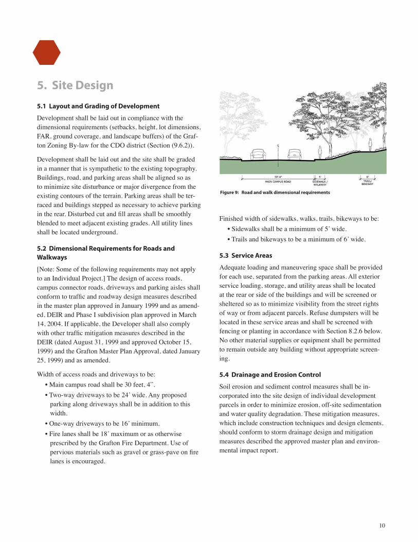
Figure 9: Road and walk dimensional requirements
10
5. Site Design
5.1 Layout and Grading of Development
Development shall be laid out in compliance with the dimensional requirements (setbacks, height, lot dimensions, FAR, ground coverage, and landscape buffers) of the Graf-ton Zoning By-law for the CDO district (Section (9.6.2)).
Development shall be laid out and the site shall be graded in a manner that is sympathetic to the existing topography. Buildings, road, and parking areas shall be aligned so as to minimize site disturbance or major divergence from the existing contours of the terrain. Parking areas shall be ter-raced and buildings stepped as necessary to achieve parking in the rear. Disturbed cut and fill areas shall be smoothly blended to meet adjacent existing grades. All utility lines shall be located underground.
5.2 Dimensional Requirements for Roads and Walkways
[Note: Some of the following requirements may not apply to an Individual Project.] The design of access roads, campus connector roads, driveways and parking aisles shall conform to traffic and roadway design measures described in the master plan approved in January 1999 and as amend-ed, DEIR and Phase I subdivision plan approved in March 14, 2004. If applicable, the Developer shall also comply with other traffic mitigation measures described in the DEIR (dated August 31, 1999 and approved October 15, 1999) and the Grafton Master Plan Approval, dated January 25, 1999) and as amended.
Width of access roads and driveways to be: • Main campus road shall be 30 feet, 4”.• Two-way driveways to be 24’ wide. Any proposed
parking along driveways shall be in addition to this width.
• One-way driveways to be 16’ minimum.• Fire lanes shall be 18’ maximum or as otherwise
prescribed by the Grafton Fire Department. Use of pervious materials such as gravel or grass-pave on fire lanes is encouraged.
Finished width of sidewalks, walks, trails, bikeways to be:• Sidewalks shall be a minimum of 5’ wide. • Trails and bikeways to be a minimum of 6’ wide.
5.3 Service Areas
Adequate loading and maneuvering space shall be provided for each use, separated from the parking areas. All exterior service loading, storage, and utility areas shall be located at the rear or side of the buildings and will be screened or sheltered so as to minimize visibility from the street rights of way or from adjacent parcels. Refuse dumpsters will be located in these service areas and shall be screened with fencing or planting in accordance with Section 8.2.6 below. No other material supplies or equipment shall be permitted to remain outside any building without appropriate screen-ing.
5.4 Drainage and Erosion Control
Soil erosion and sediment control measures shall be in-corporated into the site design of individual development parcels in order to minimize erosion, off-site sedimentation and water quality degradation. These mitigation measures, which include construction techniques and design elements, should conform to storm drainage design and mitigation measures described the approved master plan and environ-mental impact report.

Figure 10: S tone Wall
11
5.5 Materials for Hardscape
• All parking areas and driveways shall be paved with bituminous pavement.
• Building entries and drop-offs shall use pedestrian- oriented materials such as concrete or unit pavers.
• All parking areas shall be curbed with granite curbing. Sloped granite curbing may be used in areas where curbing does not abut sidewalks.
• Sidewalks shall be paved with concrete or unit pavers such as brick or stone.
• Entry plazas and patios shall be paved with concrete or unit pavers such as concrete, brick, or stone.
Visible retaining or freestanding walls shall be finished with brick, modular concrete, or stone.
5.6 Parking Requirements
The minimum parking ratios and parking space dimension-al requirements shall be as described in the Grafton Zoning By-law for the CDO district (Section 9.6.3). Plantings and screenings around parking areas shall be provided in Section 8.2.4 below. No parking areas or other vehicular surface shall be closer than 12 feet to a building line except in the case of an automobile drop-off, a loading area, or vehicular entry into the building. Parking shall be set back a minimum of 10 feet from property lines. (See Zoning By-law section 9.6.3.2). No parking lots shall be more than 1,000 feet from the buildings they serve.
Structured parking facilities shall comply with the require-ments of Section 4 herein.
Figure 11: Entry Plaza Paving
Figure 10: Stone Wall

Figure 12: Special lighting at entry plazas Figure 13:
12
6. Lighting
Lighting shall be placed in a logical and appropriate rela-tionship to the site, not only to illuminate but also to pro-vide security. The Developer shall provide lighting in areas that receive heavy pedestrian and vehicular use, and in areas that are dangerous if unlit, such as stairs and ramps, intersections, or abrupt changes in grade.
Prevention of light pollution shall also be considered in the site lighting design, by utilizing semi-cutoff and full cutoff light fixtures.
Consistent use of standard science park light fixtures shall be used to visually unify the development.
The guidelines below are intended to ensure compatibili-ty between lighting schemes for the park, the Cummings School and the lighting along Westboro Road.
6.1 Pedestrian Walkways
Lighting for pedestrian walkways shall be mercury vapor or metal halide from a semi-concealed or visible source.
The lights shall be located either at ground level or on dark colored poles of 12-foot maximum height. Fixtures shall be spaced at intervals that permit a minimum light level of 0.5-foot candles between fixtures. The fixture shall be compatible with that specified for roadway and intersection lighting below. Special decorative fixtures may be used at entry plazas and patios where a special design character is desired.
6.2 Building Exterior
The lighting of building exteriors will not be permitted. There will be no up lit buildings and no lighting off of the buildings except at the loading dock.
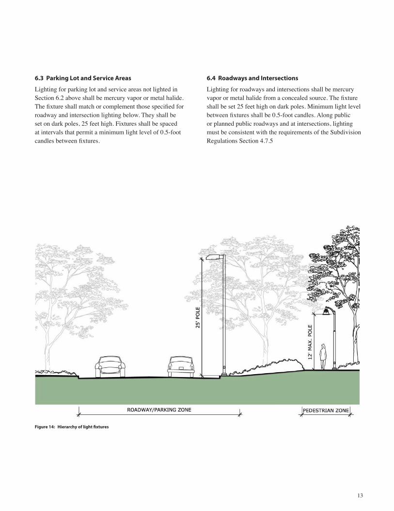
Figure 14:
13
6.3 Parking Lot and Service Areas
Lighting for parking lot and service areas not lighted in Section 6.2 above shall be mercury vapor or metal halide. The fixture shall match or complement those specified for roadway and intersection lighting below. They shall be set on dark poles, 25 feet high. Fixtures shall be spaced at intervals that permit a minimum light level of 0.5-foot candles between fixtures.
6.4 Roadways and Intersections
Lighting for roadways and intersections shall be mercury vapor or metal halide from a concealed source. The fixture shall be set 25 feet high on dark poles. Minimum light level between fixtures shall be 0.5-foot candles. Along public or planned public roadways and at intersections, lighting must be consistent with the requirements of the Subdivision Regulations Section 4.7.5

14
7. Signage
All signs and graphic symbols shall conform to the Grafton Zoning By-law and the standards set forth herein.
7.1 Signs at Entrance
One identification sign containing the building address and tenant names may be erected at the entrance to each parcel at a location deemed to be suitably visible and appropriate by review of the Board. The entrance identification sign shall be fabricated with durable, weather-protected materi-als and finishes, in accordance with the criteria in Section 9.6.4.3 of the Zoning bylaw. Recommended are:
• Posts: Tubular steel or anodized aluminum in square cross-section, not to exceed six inches by six inches.
• Panels: Steel or anodized aluminum rectangular face, bracketed by the posts. The panel shall provide for the back lighting of letters.
• Finish color and lettering styles for the signs shall be consistent with the graphic image to be established by the Developer.
7.2 Signs on Building Exteriors
Signs will be permitted on the exterior of buildings in ac-cordance with Grafton Zoning Bylaw Section 9.6.4.3.

15
8. Planting
8.1 Intent
The tree cover of the Grafton Science Park site is one of the primary physical features contributing to its park-like character. It is valuable in establishing a compartmentaliza-tion of the site into a number of separate spaces and serves to partially conceal existing campus buildings. It will also partially conceal proposed buildings, and assist in main-taining a human scale of space between buildings.
Site vegetation should be preserved and enhanced, to retain the unified character of the site, and to compartmentalize space and screen built form to create a humanly scaled setting.
8.2 Design Guidelines and Criteria for Planting
8.2.1 Tree Preservation and Protection
To the maximum extent feasible, mature or healthy trees in wooded areas should be preserved and protected from damage during construction. With Board approval, site improvements are permitted within these wooded areas. These site improvements include pedestrian paths, pedestri-an lighting, site furnishings such as benches, picnic tables and trash receptacles; planting, seeding and sodding; and improvements to existing roads and paths.
8.2.2 New Planting
In general, new planting shall be of a type and arrange-ment that replicates the dominant existing tree and lawn landscape of the site. All unbuilt areas shall be landscaped with a combination of trees, shrubs, herbaceous perennials, and turf grass in accordance with the new planting zone guidelines below.
Figure 15: N ew Planting Layout for Parking and RoadwaysFigure 15: New Planting Layout for Parking and Roadways

16
8.2.3 Area A: New Planting for Road and Driveways
Roadside planting for the site’s main access road and for new interior project roads shall consist of deciduous shade trees. Depending on existing adjacent vegetation, these plantings shall be in either regular linear rows or informal groupings. Regular rows shall be used in cases where the road abuts an open area without existing trees or where one side of the road already has existing regular rows. Infor-mal groupings may be used where the road abuts existing informal groupings of trees. With either roads or informal plantings, trees shall be a minimum of a 3.5-inch caliper and planted in numbers equivalent to one tree per 40-linear feet of road edge. (See also Subdivision Regulations Sec-tion 4.5.1). Surface treatment for all unpaved road edges shall be turf grass.
Planting along driveways on individual development par-cels shall follow the same guidelines as above for project roads; however, the developer shall have the choice of either a regular or informal pattern.
8.2.4 Area B: New Planting for Parking Lots
Parking areas shall include pavement, islands, and sur-rounding edges to a depth of 15 feet, except in those edges between parking lots and buildings. Parking lot islands shall be provided between terraced parking levels and the ends of rows of parking spaces. They shall be a minimum of 10 feet from curb to curb. The Developer shall provide a minimum of one tree per five cars in parking areas. Trees may be planted in regular rows or informal groupings as space permits. The minimum distance from tree to curb shall be five feet in islands, five feet where the curb is adjacent to a building, and eight feet at all other parking lot edges. Minimum tree size shall be a three-inch caliper. Where parking lots abut a public road, shrubs shall also screen the lot. Screening shall be sufficient to effectively screen parked cars as seen from the public road. Surface treatment for all unpaved parking lot islands and edges shall be turf grass.
8.2.5 Area C: New Planting for Building Edges and Entrances
Planting for the spaces between buildings and parking lots and at building entrances shall be selected and arranged with the intent of creating human scale outdoor spaces, which recognize pedestrian activity in this zone and the need to identify building entrances. A full range of ground-covers, shrubs, and trees may be used in this zone to create interest and a degree of landscape detail appropriate to the pedestrian scale. All unpaved surfaces not planted with trees, shrubs, or groundcovers shall be turf grass.
Figure 16: I llustrative Planting at Area B - Parking LotsFigure 16: Illustrative Planting at Area B - Parking Lots

17
8.2.6 Area D: New Planting for Service Areas
All building service areas shall be screened with plantings. Screening shall be sufficient to conceal the service area ac-tivity from off-site view. At installation, the screening shall be effective to a height of four feet. At maturity, the plant screen shall be effective to a minimum height of eight feet.
8.2.7 Area E: New Planting for Edges of Development Abutting Natural Areas
Plantings shall be provided to blend the development edges with the abutting naturalistic areas, to provide not only aesthetic backdrop but also add biodiversity and habitat value. Recommended plants for these areas are native trees, shrubs, and groundcovers that are appropriate to the soil and hydrological conditions of the specific plating site. Special consideration shall be given to areas where the development abuts existing wetland areas and buffers.
Figure 18: I llustrative Planting at Area E - Edges Abutting Natural AreasFigure 17: I llustrative Planting at Area C - Building Edges Figure 18: Illustrative Planting at Area E - Edges Abutting Natural AreasFigure 17: Illustrative Planting at Area C - Building Edges

18
8.3 Plant Lists 8.3.1 8.3.2 8.3.3 8.3.4 8.3.5 Area A: Area B: Area C: for Area D: Area E: for Roads for Building for Edges and Parking Edges and Service Abutting Driveways Lots Entrances Areas Natural Areas
Deciduous Trees:
Acer pseudoplatanus: Planetree Maple • • •
Acer saccharum: Sugar Maple • • •
Fagus grandifolia: American Beech • • •
Fagus sylvatica: European Beech • • •
Gleditsia triacanthos intermis: Thornless Honeylocust • • •
Quercus alba: White Oak • • •
Quercus coccinia: Scarlet Oak • • •
Quercus palustris: Pin Oak • • •
Quercus rubra: Red Oak • • •
Zelkova serrata: Japanese Zelkova • • •
Acer rubrum: Red Maple • • •
Cercidiphyllum japonicum: Katsura Tree • •
Cladrastis lutea: Yellowwood • • •
Fraxinus species: Ash • •
Ginkgo biloba: Ginkgo (Male only) • •
Gymnocladus dioica: Kentucky Coffee Tree • •
Phellodendron Amurense: Amur Cork Tree • •
Sophora japonica: Japanese Pagoda Tree • •
Tilia species: Linden • •
Small Ornamental Trees:
Amelanchier canadensis: Shadblow • •
Betula Nigra: River Birch • •
Carpinus caroliniana: American hornbeam •
Cornus florida ‘Rutgers’ hybrid (disease resistant) •
Cornus kousa: Japanese dogwood •
Cornus mas: Cornelian Cherry Dogwood • •
Crataegus species: Hawthorne •
Cercis canadensis: Redbud •
Chionanthus virginicus: White Fringe Tree •
Liquidambar styraciflua: Sweetgum • •
Malus species: Crabapple •
Ostrya virginiana: Hop Hornbeam •
Prunus species: Cherry •
Sassafras albidum: Sassafras •

19
8.3 Plant Lists (continued) 8.3.1 8.3.2 8.3.3 8.3.4 8.3.5 Area A: Area B: Area C: for Area D: Area E: for Roads for Building for Edges and Parking Edges and Service Abutting Driveways Lots Entrances Areas Natural Areas
Coniferous Trees: Larix decidua: Eastern Larch • Picea abies: Norway Spruce • • Picea glauca: White Spruce • • Pinus species: Pine • • • •Thuja occidentalis: Arborvitae • • •
Shrubs: Berberis species: Barberry • • Chaenomeles species: Quince • • Cornus species: Dogwood • • •Cotoneaster divaricata: Spreading Cotoneaster • • Hamamelis virginiana •Ilex species: Holly • • Kalmia latifolia: Mountain Laurel • • •Leucothoe fontanesiana: Drooping Leucothoe •Ligustrum species: Privet • • Lindera benzoin: Spice Bush •Myrica pennsylvanica: Bayberry • • Pieris species: Andromeda • • Rhododendron cultivars: Rhododendron and Azalea • • • Rhododendron species (native): Native Rhododendron and Azalea •Rhodotypus scandens: Black Jetbead • • Ribes alpinum: Alpine Currant • • Taxus species: Yew • • • Vaccinium corymbosum: Highbush Blueberry • • •Viburnum species: Viburnum • • •
Groundcovers: Arctostaphylos uva-ursi: bearberry •Fern Species •Hedra helix: English Ivy • Hosta species: Hosta • Juniperus horizontalis: Creeping Juniper • •Ornamental grasses • •Pachysandra terminalis: Japanese Spurge • Parthenocisis quinquifolia: Virginia Creeper • Parthenocisis tricuspidata: Boston Ivy • Stephanandra incisa “crispa”: Cutleaf Stephanandra • Vinca minor: Myrtle •

20
Attachments