Maritime Managment - Diploma, Advanced Diploma, Graduate Diploma
Upload
michael-clarkeCategory
view
213download
1description

02. BurnDevelopment document &
Proposal summary
DS10
Michael Clarke

pg. ii
Brief_02: Burn
Michael Clarke pg. iii
Summary of ContentThis book documents the research undertaken to inform my design considerations for the second brief in the fi rst year of the Graduate Diploma in Architecture (RIBA Part II) at the University of Westminster.
In addition it documents the process of design work including sketch proposals and both analogue and digital experimentation. Images and drawings of the fi nal proposal submitted to the burning man arts committee are included at the end for reference.

pg. 01
Brief_02: Burn

Michael Clarke pg. 02
Summary of Contents Page No.
Brief 02: Burning Man - Inclusive society
Background Research on the Burning Man Festival 04
A brief summary of the history, size and the beginner’s survival guide to the Burning Man Festival in the Black Rock Desert, Nevada
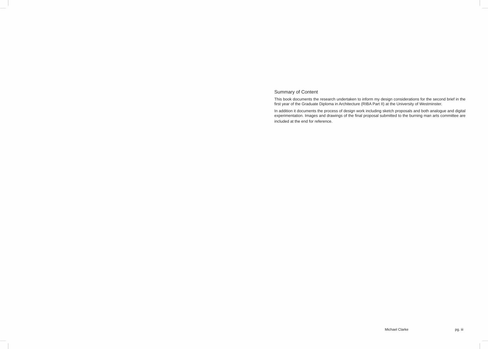
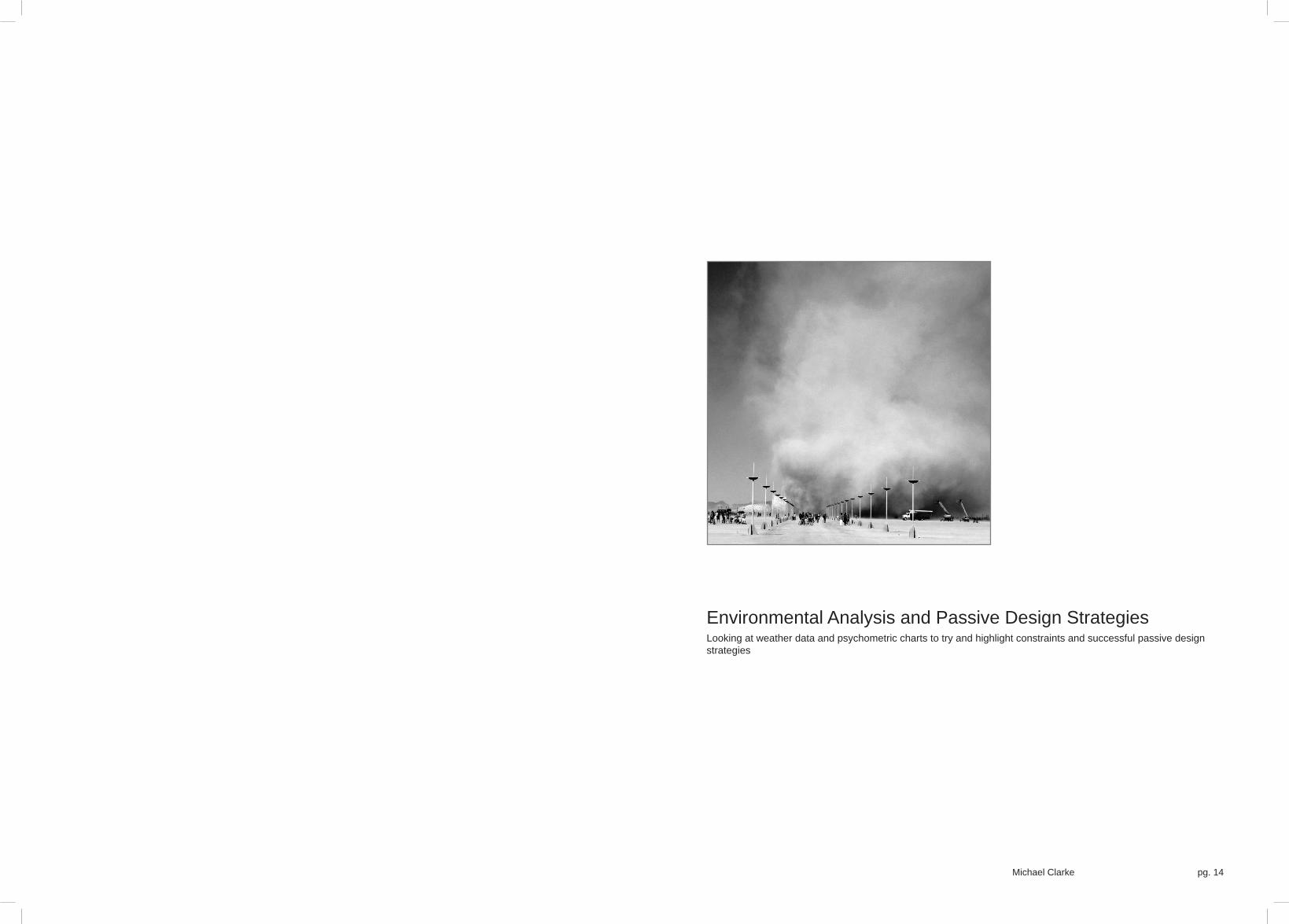
Environmental Analysis and Passive Design Strategies 14
Looking at weather data and psychometric charts to try and highlight constraints and successful passive design strategies
Initial responses 22
Material research, precedent studies and early sketch proposals for an art pavilion at Burning Man Festival
Design Development and Final Proposal 50
Refi ning the proposal, further experimentation and research
Burning Man Arts Grant Submission 74
Final proposal renders, diagrams, animation and specifi cations including outline costings and the draft submission for the Burning Man arts grant

pg. 03
Brief_02: Burn

Michael Clarke pg. 04
Background Research on the Burning Man Festival
A brief summary of the history, size and the beginner’s survival guide to the Burning Man Festival in the Black Rock Desert, Nevada

pg. 05
Brief_02: Burn
Mission StatementOur mission is to produce the annual event known as “Burning Man” and to guide, nurture and protect the more permanent community created by its culture. Our intention is to generate society that connects each individual to his or her creative powers,to participation in community, to the larger realm of civic life, and to the even greater world of nature that exists beyond society. We believe that the experience of Burning Man can produce positive spiritual change in the world. To this end, it is equally importantthat we communicate with one another, with the citizens of Black Rock City and with the community of Burning Man wherever it may arise. Burning Man is radically inclusive, and its meaning is potentially accessible to anyone. The touchstone of value inour culture will always be immediacy: experience before theory, moral relationships before politics, survival before services, rolesbefore jobs, embodied ritual before symbolism, work before vested interest, participant support before sponsorship. Finally, inorder to accomplish these ends, Burning Man must endure as a self-supporting enterprise that is capable of sustaining the livesof those who dedicate themselves to its work. From this devotion spring those duties that we owe to one another. We will alwaysburn the Man.
BURNING MAN
Ten PrinciplesRadical InclusionAnyone may be a part of Burning Man. We welcome and respect the stranger. No prerequisites exist for participation in our community.
GiftingBurning Man is devoted to acts of gift giving. The value of a gift is unconditional. Gifting does not contemplate a return or an exchange for something of equal value.
Decommodifi cationIn order to preserve the spirit of gifting, our community seeks to create social environments that are unmediated by commercial sponsorships, transactions, or advertising. We stand ready to protect our culture from such exploitation. We resist the substitution of consumption for participatory experience.
Radical Self-relianceBurning Man encourages the individual to discover, exercise and rely on his or her inner resources.

Michael Clarke pg. 06
Radical Self-expressionRadical self-expression arises from the unique gifts of the individual. No one other than the individual or a collaborating group can determine its content. It is offered as a gift to others. In this spirit, the giver should respect the rights and liberties of the recipient.
Communal EffortOur community values creative cooperation and collaboration. We strive to produce, promote and protect social networks, public spaces, works of art, and methods of communication that support such interaction.
Civic ResponsibilityWe value civil society. Community members who organize events should assume responsibility for public welfare and endeavor to communicate civic responsibilities to participants. They must also assume responsibility for conducting events in accordance with local, state and federal laws.
Leaving No TraceOur community respects the environment. We are committed to leaving no physical trace of our activities wherever we gather. We clean up after ourselves and endeavor, whenever possible, to leave such places in a better state than when we found them.
ParticipationOur community is committed to a radically participatory ethic. We believe that transformative change, whether in the individual or in society, can occur only through the medium of deeply personal participation. We achieve being through doing. Everyone is invited to work. Everyone is invited to play. We make the world real through actions that open the heart.
ImmediacyImmediate experience is, in many ways, the most important touchstone of value in our culture. We seek to overcome barriers that stand between us and a recognition of our inner selves, the reality of those around us, participation in society, and contact with a natural world exceeding human powers. No idea can substitute for this experience.

pg. 07
Brief_02: Burn
BURNING MAN FACTS & FIGURES

Michael Clarke pg. 08

pg. 09
Brief_02: Burn
BURNING MAN SURVIVAL GUIDE
ContentsThe burning man festival organisers publish a survival guide with what to bring, the rules of the camp etc. every year to help peopleprepare for their experience at burning man and to make sure an environment is created in which everybody is safe and can have fun. Over the next few pages I have taken points from that survival guide to highlight potential problems that my pavilion couldprovide solutions to, in short to inform my programme and form.
• Arriving at Burning Man - what to bring and what not to bring
• Protecting the environment - leave no trace, waste management and water management
• Survival - desert life and climate and how to cope
• Community - ensuring an environment everyone can enjoy including the larger context outside Black Rock City and how to make the most of your time at Burning Man.
• Safety and Law - following the law and ensuring a safe environment
• Exodus - leaving the desert with no trace
Upon arrivalThe gates do not open until the entire site is ready and all of the safety and sanitation features have been set up. When the gatesare opened hundreds of cars pile in and it can take a long time to enter the site, you are advised to delay arrival if you wish to miss the queues. Every car is searched and all occupants of the car must have their tickets or photo ids and confi rmation number if picking up tickets. The cars are searched to ensure that none of the banned items can get through into Black Rock City, you canbe turned away or at least to the back of the queue if you have any items. Most of the banned substances are purely to aid the clean up effort after and ensure that no trace will be left - one of the primary goals of Burning Man. Anything on the ground thatshouldn’t be is referred to as MOOP (Matter Out Of Place).
From looking at the survival guide lists of what to bring and what not to bring (see the three images to the right) the key issuesappear to be:• The heat during the day
• The cold temperatures at night
• Management of supplies to ensure everything is looked after and not left on the ground
• Storage of supplies
• The dust and the storms
• Ensuring plenty of water to drink, making sure all that water is brought with you
• A consideration for everyone at the festival
TemperatureMinimising MOOP Dust
WaterSupplyTransportation Participation

Michael Clarke pg. 10
Essentials:
• Strong tent
• Warm sleeping bag (temperatures can fall to around 5°C at night)
• Warm clothes for the night
• 1.5 gallons of water per person per day
• Enough food and drink for your group
• An extensive fi rst aid kit
• Any prescription medicines, contact lenses etc.
• Fire extinguishers
• Garbage and recycling bags to clear up
• A torch and spare batteries to see and be seen at night
• Sun cream and sunglasses although at the hottest part of the day you are encouraged to seek shelter and save your energy for the rest of the day
• In addition you must have your ticket or photo id card and confi rmation to collect tickets.
Suggested:
• Shading structures and umbrellas to protect from the heat
• A wide brimmed hat, chin straps are recommended due to the sometimes high winds
• A bike for getting around, balloon tires are best and you should have a lock and lights for safe travel at night
• A tire repair kit
• A cooking stove if you wish to heat food or liquids
• A portable shower providing it has a drain that can collect the grey water
• Water tight protective bags for electrical equipment
• Ear plugs - some people may be up all night beside you!
• Lotion and lip balm to protect against dry or cracked skin
• Portable ashtrays that can be sealed
• An am/fm radio to tune into BMIR radio whilst you are at the festival
• Dust masks and goggles to protect from the dust storms (common)
• Heavy duty tent stakes to make sure everything is strongly grounded in the case of storms, rebar can be used effectively.
• Cut tennis balls or plastic bottles to sit on the tent pegs to stop people injuring themselves
• Extra set of car keys in case you lose them
• In addition you are recommended to bring camp markers and lots of costumes to help you participate and fi nd your camp easily.
Do not bring (you can be refused entry):
• Glass containers of any type
• Excess packaging - for example take the bag of cereal, not the box as well
• Loose glitter
• Nuts in their shells
• Too much fresh produce, it will start to smell before you can dispose of it at the end of the week
• Styrofoam coolers will disintegrate into lots of pieces and will not last the week
• Gravel
• Straw or hay bales
• Feathers including boas
• Any plants, live or dead in addition to anything else that may break up or blow away in the wind
• Explosives, aerial fl ares, fi reworks or rockets
• Any kind of fi rearm including bb guns and paintball guns
• In addition, any mutant vehicles not pre registered will be turned away and any motorcycles that were not used as the primary method of transportation to burning man.
Temperature
WaterSupply

pg. 11
Brief_02: Burn
BURNING MAN SURVIVAL GUIDE
Protecting the environmentOf the ten key principles that Burning Man runs on only one is chiefl y concerned with the effect of the festival on the environment which is Leave No Trace. Part of being allowed to use the Black Rock Desert Playa for the festival is down to regular inspectionsby the Bureau of Land Management. The BLM is also responsible in part for the current location and layout of the Black Rock City. They require an organised layout that doesn’t impact on other users of the playa in order to issue a permit to grant camping rights.
Burning Man is the largest Leave No Trace festival in North America and actively tries to promote the Leave No Trace principlesbeyond the extent of the festival. It is a very simple principle that literally translates its name to its practice making sure that you leave an environment as or better than you found it.
Since 2006 Burning Man LLC has also come up with an environmental statement:
‘Black Rock City LLC is committed to utilizing environmentally favorable solutions as they become fi nancially sound alternatives to the use of fossil fuels and non-renewable materials. We encourage our staff and participants to use these alternatives in their camps in Black Rock City, and further to promote and encourage environmental awareness and make use of emerging technologies. We are determined to promote and continue to support the Leave No Trace principles, the use of renewable energy, the use of non-fossil fuels, recycling valuable reusable materials, and composting organic waste materials when ever possible.
We are open to suggestions toward making the Burning Man experience environmentally sound and we will utilize new methods and technology as they become suitable to our needs. Help us make Black Rock City environmentally viable.
Signed,
Board of Director
Black Rock City LLC’
Temperature
WaterSupply
The six R’sThere are six guiding principles to help participants at Burning Man respect the environment and meet the Leave No Trace principles:
• Respect - respect for all things from the ground to the sky
• Rethink - Do i really need this? The impact on the environment? where did it come from? What happens after?
• Reduce - reduce waste, driving trips and disposables
• Reuse - can it be reused before being recycled?
• Recycle - recycle everything possible that can’t be reused
• Restore - Be the solution, always try and leave things better or at least the same as you found it.
PlanningThe survival guide offers tips for reduction, reuse and recycling during the festival in order to minimise participants impact. It’s primary focus is on reducing the MOOP in a fi rm belief that anything lying around leads to further matter being added to it.
Each camp is recommended to have a ‘Leave No Trace Planner’. This person is responsible for setting out a management plan to be carried out during the week ensuring minimal rubbish. There should also be a designated ‘Leave No Trace Monitor’ who is the last person to leave the camp. At the end of the week the entire camp should form lines crisscrossing their space to ensure that no MOOP is left on the ground.
At the end of the week any rubbish should be taken with you including grey water that hasn’t been recycled. No grey water can be dumped on the Playa. This is to ensure that Black Rock City continues to get its permit for future burning man festivals.

Michael Clarke pg. 12
TemperatureMinimising MOOP Dust
WaterSupplyTransportation Participation

pg. 13
Brief_02: Burn
Michael Clarke pg. 14
Environmental Analysis and Passive Design StrategiesLooking at weather data and psychometric charts to try and highlight constraints and successful passive design strategies

pg. 15
Brief_02: Burn
Environmental AnalysisClimate and Appropriate ResponsesBlack Rock City is built on the Playa of the Black Rock Desert in Nevada. The Playa is a silt alkaline salt pan 3848ft above sealevel. The longest stretch of the Playa reaches 27 miles and with the widest point at 12 miles it is the second largest expanse of fl at ground in the Northern Hemisphere. Although an old lake bed thousands of years ago it is a very dusty and dry environment, there is little humidity in the air. It can also get extremely hot during the day, particularly in Summer however as with most deserts,the temperature can fall dramatically at night.
This page uses Ecotect’s Weather Tool to briefl y analyse the type of climate and suggest possible design solutions to increase average comfort levels within the climate. The charts to the right are all psychometric charts with various overlays (see legend).The chart runs along two axis, with the dry bulb temperature in °C along the bottom axis and absolute humidity running vertically. The lines crossing the graph are the relative humidity (curved), wet bulb temperature (dashed diagonals) and vapour pressure (solid verticals).
The tool allows you to look at temperatures and humidities as cumulative frequency plots or specifi c data points and overlays areas to show temperatures and humidities that fall within an average comfortable range for different levels of activity. It also then allows overlays for various passive design strategies to try and increase the range of values within the comfort levels.
All the weather data used in this analysis is from Las Vegas, Nevada, a similar desert climate not far from Black Rock Desert andthe closest set of weather data within Ecotect’s database.
>> Pyschometric Chart Legend:
01. The yellow boxes highlight climate types based on the temperatures and humidities recorded. The blue line charts maximum values across the year. The letters along the line relate to the months of the year. The Burning Man festival takes place at the end of August and the start of September, all of these months fall within the hot and dry climate category.
02. The data points plotted in this case are a cumulative frequency chart for the month of August. Overlaid are the most suitableactive cooling strategies for any points that fall within their areas. The majority of points recorded fall within the ventilate or evaporative category with a few outside points best solved with purely evaporative cooling or ventilation.
03. The same chart as 02, but for September. Again it shows a climate that is dry enough for evaporative cooling to be effectivewhere air conditioning is unnecessary.

Michael Clarke pg. 16
<< Images of Black Rock Desert
01. Natural springs north and east of the Playa
02. Vehicle tracks left in the mud of the Playa
03. Silt dunes and scrubland
04. A plane takes off above the dry and dusty landscape of the desert
05. In the Summer the Playa cracks like baked mud
06. Dust storms are common, particularly with increased activity stirring up the dust from the surface
07. Another silt dune pushed up by the wind and swelling below the Playa’s surface.
pg. 17
Brief_02: Burn
Environmental AnalysisPassive Design Strategies
Ecotect has some in built analysis of passive design strategies and their effectiveness in varying climates. Based on the psychometric charts that I have already looked at, it can also overlay the effect of a particular strategy, or even multiple strategies on the range of comfortable temperatures and humidities. Different passive design strategies can be looked at and compared to help decide on the best ones to incorporate in a design. These are not difi nitive and even the psychometric chart should only be used as a guide however they can give an indication.
I have already seen that ventilation or evaporative cooling are the best strategies for cooling in the Nevada desert climate however due to the fl uctuating temperatures between day and night I am also looking at thermal mass. As the pavilion or theme camp will be outside in the desert it will be very easy to let air movement through so I am not comparing ventilation effects - it is not the same as a closed environment.
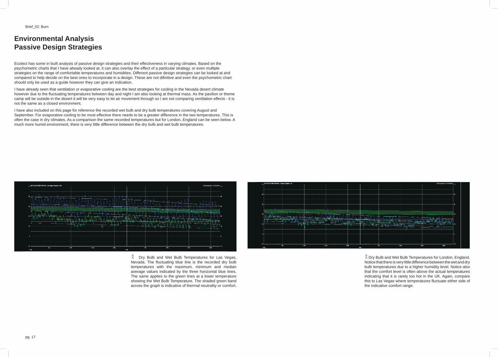
I have also included on this page for reference the recorded wet bulb and dry bulb temperatures covering August and September. For evaporative cooling to be most effective there needs to be a greater difference in the two temperatures. This isoften the case in dry climates. As a comparison the same recorded temperatures but for London, England can be seen below. A much more humid environment, there is very little difference between the dry bulb and wet bulb temperatures.
Dry Bulb and Wet Bulb Temperatures for Las Vegas, Nevada. The fl uctuating blue line is the recorded dry bulb temperatures with the maximum, minimum and median average values indicated by the three horizontal blue lines. The same applies to the green lines at a lower temperature showing the Wet Bulb Temperature. The shaded green band across the graph is indicative of thermal neutrality or comfort.
>> Dry Bulb and Wet Bulb Temperatures for London, England. Notice that there is very little difference between the wet and dry bulb temperatures due to a higher humidity level. Notice also that the comfort level is often above the actual temperatures indicating that it is rarely too hot in the UK. Again, compare this to Las Vegas where temperatures fl uctuate either side of the indicative comfort range.
>>

Michael Clarke pg. 18
<< Psychometric chart overlays
The two graphs below show the effects of fi rst, thermal mass and bottom, evaporative cooling on the range of temperatures that could be included in a comfortable range if that design strategy was put into place.
The large image above shows the combined effect of both strategies on one chart. All of these three charts are for a temperature range in August. Although a few points, particularly in the higher temperatures fall outside of the comfort zone the design strategies include most of the data showing them to be largely successful options. As Burning Man is held right at the end of August, it is likely that these higher temperatures will not be experienced anyway.
<< Psychometric chart overlays
The three graphs on this page show the temperature and humidity ranges for September. The same two design strategies have been applied. Again they are largely successful although the chart shows there is less humidity in the air so that thermal mass becomes less effective at the higher temperatures. The design strategies are struggling to help the cooler dryer ranges. Again, these values are likely to be recorded towards the end of September and not during Burning Man.

pg. 19
Brief_02: Burn
Passive Design StrategiesEvaporative Cooling
Evaporative cooling is a very simple process illustrated by the diagram on the right. Water is soaked into a material which actsas an evaporative pad. The pad needs to not just let the water fall rapidly into the collection point but instead hold enough in the material. As the warm dry air passes through the material/pad it picks up moisture (this is why it works best when there is littlehumidity) making it not only cooler but more humid also. The air can then be circulated around wherever it needs to be. In the topdown diagram there needs to be a collective pan to take any excess moisture.
I am aiming to try and recreate the effect, by replacing the evaporative pad with a material or thread network based on my bunching experiments. These will be a suitable material that can wick water from below up the structure. The warm air passing through the thread network will not only be cooled by the water wicked up, but increase the speed of the wicking by ensuring a constant moisture gradient.
Water drawn up from tray through capillary action
Thread network sucks up the water from below through capillary actionand forms a mesh to act as an evaporative pad
Hot dry air passes through the thread mesh/network and takes on moisture cooling the air. Also by evaporating water from the threads it causes the wicking process to improve and speed up.

Michael Clarke pg. 20
Top specifi c heat capacities (kJ/kg.K) of common liquids and fl uids:
Substance Phase cp
(J/(g·K))
Ammonia, 32°F 4.6
Ammonia, 104°F 4.86
Ammonia, 176°F 5.4
Ammonia, 212°F 6.2
Ammonia, 238°F 6.74
Water, fresh 4.19
Water, sea 36°F 3.93
Sodium chloride 3.31
Sodium hydrate 3.93
Milk 3.93
Calcium Chloride 3.06
Human Urine
(0.05g of solutes per g of urine), 73°F 4.019
Human Urine
(0.90g of solutes per g of urine), 73°F 1.536
Passive Design StrategiesThermal Mass
Thermal mass is a strategy that allows a more constant temperature throughout the day and night rather than greatly swinging temperatures. During the day the thermal mass material absorbs heat from the sun. This helps to cool the surrounding environment by reducing the radiation refl ected. At night when the outside air temperature is much cooler the thermal mass starts to radiate heat warming its surroundings.
Large amounts of concrete, earth or stone are often used as thermal mass materials in architecture. It’s effect can be felt perhaps at its most when entering massive churches or mosques where the sheer volume of stone and little daylight entering a space acts to create a much cooler environment.
I am planning on using water throughout my structure (partly for grey water storage and partly to try and evaporate the grey water) to act as a thermal mass. From the specifi c heat capacity values, water is second only to ammonia as a thermally massive material, far better than concrete and much more readily available. The table also shows that the presence of salts andammonia within the water will not be a bad thing for the thermal mass.
Specifi c heat capacity of building materials:
Substance Phase cp
(J/(g·K))
Asphalt solid 0.920
Brick solid 0.840
Concrete solid 0.880
Glass, silica solid 0.840
Glass, crown solid 0.670
Glass, fl int solid 0.503
Glass, pyrex solid 0.753
Granite solid 0.790
Gypsum solid 1.090
Marble, mica solid 0.880
Sand solid 0.835
Soil solid 0.800
Wood solid 1.7 (1.2 to 2.3)
Above shows the pvc tubing I am proposing to use to transport the water around the structure. This provides a larger surface areafor the removal of grey water through evaporation, larger storage for grey water and a larger surface area of thermal mass.

pg. 21
Brief_02: Burn

Michael Clarke pg. 22
Initial responses
Material research, precedent studies and early sketch proposals for an art pavilion at Burning Man Festival
pg. 23
Brief_02: Burn
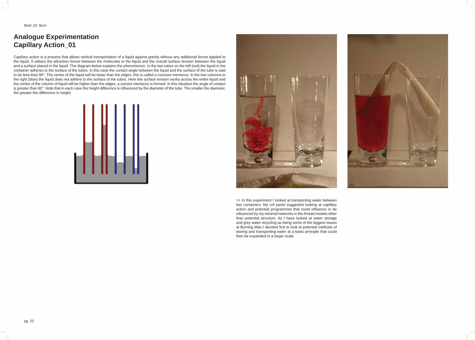
>> In this experiment I looked at transporting water between two containers. My crit panel suggested looking at capillary action and potential programmes that could infl uence or be infl uenced by my minimal networks in the thread models other than potential structure. As I have looked at water storage and grey water recycling as being some of the biggest issues at Burning Man I decided fi rst to look at potential methods of storing and transporting water at a basic principle that could then be expanded to a larger scale.
Analogue ExperimentationCapillary Action_01Capillary action is a process that allows vertical transportation of a liquid against gravity without any additional forces applied to the liquid. It utilises the attraction forces between the molecules in the liquid and the overall surface tension between the liquidand a surface placed in the liquid. The diagram below explains the phenomenon. In the two tubes on the left (red) the liquid in the container adheres to the surface of the tubes. In this case the contact angle between the liquid and the surface of the tube is said to be less than 90°. The centre of the liquid will be lower than the edges, this is called a concave meniscus. In the two columns to the right (blue) the liquid does not adhere to the surface of the tubes. Here the surface tension works across the entire liquid and the centre of the column of liquid will be higher than the edges, a convex meniscus is formed. In this situation the angle of contactis greater than 90°. Note that in each case the height difference is infl uenced by the diameter of the tube. The smaller the diameter, the greater the difference in height.
02.01.

Michael Clarke pg. 24
03. 04.
05.
01. The set up for my fi rst experiment uses two glasses, one full of water and one empty. I have added red food dye to highlight the water movement. As a medium for transporting water I am using a kitchen towel.
02. The kitchen towel is rolled up and placed between the two glasses ensuring one end is below the surface of the water. The paper towel is essentially a whole network of tiny tubes that function with capillary action.
03. The water begins to siphon into the empty container. This continues as long as there is a moisture gradient in the ‘wicking’ material.
04. The water continues to siphon although is paler with a lot of the dye seemingly left in the paper towel.
05. The liquid between both glasses levels out, there no longer being a moisture gradient between the two. It is now in a state of equilibrium with water fl owing in neither direction. I would like to try raising the paper towel in one glass to see if water can continue to fl ow.
pg. 25
Brief_02: Burn
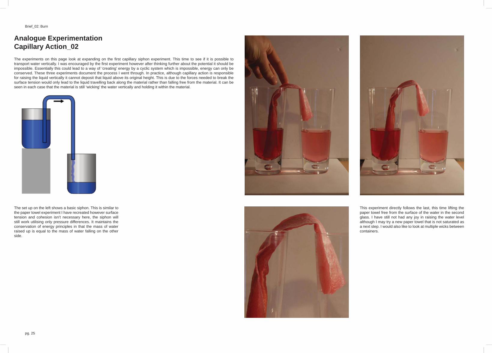
Analogue ExperimentationCapillary Action_02The experiments on this page look at expanding on the fi rst capillary siphon experiment. This time to see if it is possible to transport water vertically. I was encouraged by the fi rst experiment however after thinking further about the potential it should be impossible. Essentially this could lead to a way of ‘creating’ energy by a cyclic system which is impossible, energy can only beconserved. These three experiments document the process I went through. In practice, although capillary action is responsible for raising the liquid vertically it cannot deposit that liquid above its original height. This is due to the forces needed to break the surface tension would only lead to the liquid travelling back along the material rather than falling free from the material. It can be seen in each case that the material is still ‘wicking’ the water vertically and holding it within the material.
This experiment directly follows the last, this time lifting the paper towel free from the surface of the water in the second glass. I have still not had any joy in raising the water level although I may try a new paper towel that is not saturated as a next step. I would also like to look at multiple wicks between containers.
The set up on the left shows a basic siphon. This is similar to the paper towel experiment I have recreated however surface tension and cohesion isn’t necessary here, the siphon will still work utilising only pressure differences. It maintains the conservation of energy principles in that the mass of water raised up is equal to the mass of water falling on the other side.

Michael Clarke pg. 26
This page shows an attempt at utilising plastic bottles, a potential building material for the same purpose of raising the water vertically. Although the water is within the top bottle in the paper towel (I have unscrewed the lid to check) it is not dropping freely into the top container.
Basically a variation of the bottles experiment but with a larger height difference. I was hoping that the potential for greater evaporation at the top could lead to a larger moisture gradient and faster capillary action however this experiment has also reached a stage where the entire wick is wet but no water is being collected in the top glass.

pg. 27
Brief_02: Burn
Analogue ExperimentationCapillary Action_03
A closer look into the best materials with wicking properties was needed to help determine the best material for my pavilion. Whichmaterial would be fastest, which material would transport water the highest, which material allowed the colour to be transportedeasily without fading or absorbing colour and fi nally which material may be able to keep working throughout the week without becoming saturated and losing its moisture gradient. Theoretically this should always work due to the constant evaporation at theend however additional ‘wicks’ may be needed within the containers/bottles to draw water from the material. I started with a simpleset up that could be used to simultaneously test different materials whilst allowing air movement over each material. The designfor the experiment can be seen below.
A ply sheet with variable width holes is slotted into the frame above the tray below. This will hold the materials to be tested and can be removed to allow different tops to be placed in later.
An acrylic container will hold the water with the addition of food dyes, fl orescent dyes and salt and dust.
Your two bottle demo may appear to cause water to move upwards. The mechanism might be that a small amount of the vapour is captured in the upper bottle and condenses back into water. Is the condensate red or clear? What percentage of the loss from the lower bottle is captured in the upper bottle? You could try wrapping plastic tape around the exposed wick, or enclose it in sealed plastic tubing, to eliminate evaporation losses and see what happens.
Flying right off at a tangent: you can have a perpetual fountain in a superfl uid rising through a capillary. There is a video of a fountain that never stops.
Trees move water up to the leaves by capillary action, where most of it evaporates from the leaves. It’s the evaporation that draws up more. So long as you are content for the liquid to be evaporated, capillary action allows you to raise it up higher-that’s what a wick does. The tree trunks are full of very very thin pipes in which the water rises. On a hot day, it is said that a microphone placed on the trunk of a tall tree can hear the pings (or reverberations) as the thread of water in individual pipes regularly breaks when the “suck” exceeds the force of attraction between the water molecules and a vapour lock momentarily forms, then repairs itself.

Michael Clarke pg. 28

pg. 29
Brief_02: Burn
Precedent StudiesLars Spruyboek - Guadalajara Library

Michael Clarke pg. 30
pg. 31
Brief_02: Burn
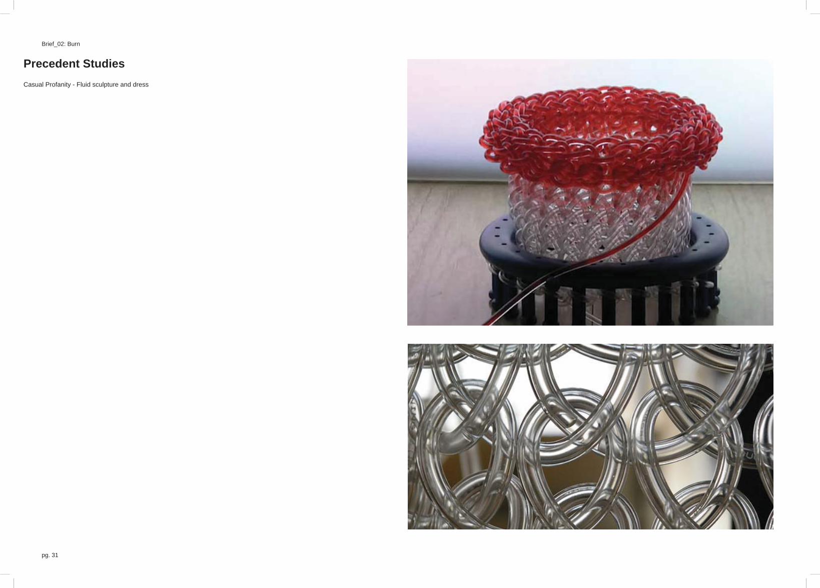
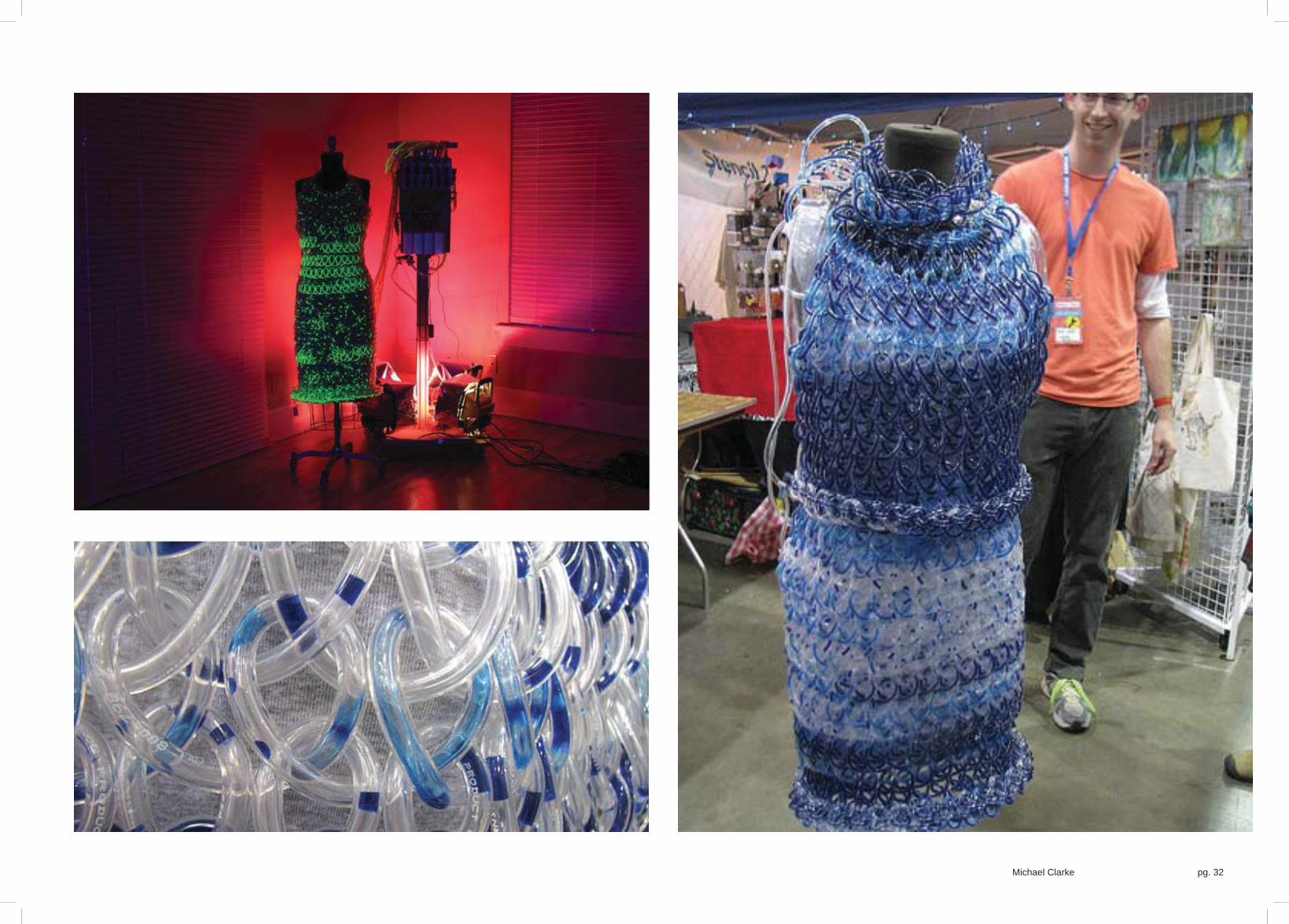
Precedent StudiesCasual Profanity - Fluid sculpture and dress
Michael Clarke pg. 32

pg. 33
Brief_02: Burn
Central thread network wicks up the grey water and forms a mesh over the cone to provide evaporative cooling
Water in the tubes serve as thermal mass for the structure.
Water in the tubes initially spiralled around a cone shape. The pressure differences utilise the venturi effect to speed up the infl owing air and increase the evaporative cooling effect of the wicking central thread mesh.
Need a way of transporting the water back to the higher tank. Potentially through pressure on an elevated dancefl oor forcing water uphill.
Sketch ProposalsThis page shows some initial sketch ideas. It does not intend to illustrate a fully resolved plan and overall form. I hope to informthe plan through further research and exploration of programme and social function in addition to practical needs. The overall formand scale I hope to ‘fi nd’ through exploration and experimentation into air movement, exposed thermal mass surface and structural limitations. I hope to achieve this through both physical models and digital analysis.
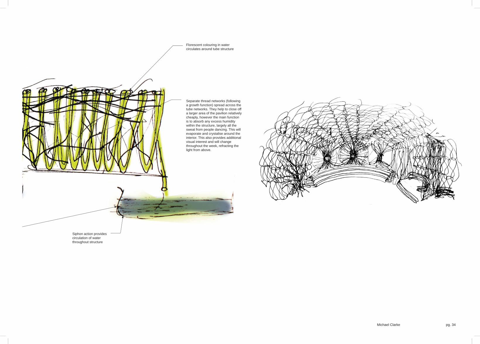
Early Sketch Visualisation - Night time clubThe image is an early visual to explore the potential aesthetic at night and how the structure may evolve. It looks at the threeprocesses outlined in the initial sketch proposals showing the crystallisation and evaporative cooling networks. It also shows the potential for seating and form from the same continuous tube with the fl ourescent lighting throughout the structure and the potential for multiple colours.
I do not like the single large space beneath a vault and feel that the form needs a lot of further exploration. The quality of the image isn’t great but I feel I can use it as a starting point for design exploration.
Michael Clarke pg. 34
Florescent colouring in water circulates around tube structure
Siphon action provides circulation of water throughout structure
Separate thread networks (following a growth function) spread across the tube networks. They help to close off a larger area of the pavilion relatively cheaply, however the main function is to absorb any excess humidity within the structure, largely all the sweat from people dancing. This will evaporate and crystalise around the interior. This also provides additional visual interest and will change throughout the week, refracting the light from above.

pg. 35
Brief_02: Burn
MichaelClarke DS10
Burning Man - Inclusive society
Defi ning a pattern for any surfaceIf I’m going to use a continuous looping tube for my structure it needs to be made stronger and the necessary material to cover an area needs to be reduced. The more tubes I have the better the thermal mass capabilities and the more the evaporative cooling will work, I need to reduce hot air allowed into a space that is being cooled from another direction. In addition, visual interest can be improved by patterning the tubes, not just the water inside.
I looked at a looping pattern that translated in the x direction every time it looped in order to make sure it could cover a space. in addition the loops had to be big enough at the top and bottom to allow multiple layers to overlap. The pattern I came up with canbe defi ned by points on a grid, turning those points into control points for a b-spline curve. It can be stretched in either the x or y directions. This page explores the pattern across a shell and then mapped onto any surface. The more u and v curves on a surfacethe tighter knit the pattern can be and therefore a more accurate representation of the initial surface. This would also mean morematerial however. Fig. 01 illustrates how the pattern works.
>> 02 A crude, initial model to look at the siphoning capability of the PVC/Polypropylene tubing;
03 The weaved pattern hanging loosely on a wall;
04 The same weaving pattern although much closer knit adds strength to be able to stand freely;
05- These are a series of digital explorations of the pattern across an arched surface. In each image the top half 08 shows the initial surface U and V curves used for construction lines and the curve pattern drawn on top. The bottom half shows a render of the curve standing alone. The series of images form a sequence with the number of u curves increased in each case allowing more repetition of the pattern. Figure 06. shows no interlocking of the patterns whereas 07 and 08 show the pattern’s overlapped by a single grid line.
04.03.
02.
Pattern:
• Start at edge of surface at nominal point 0,9
• First control point one across at 1,9
• Second control point below and to the right at 2,8
• Third point x distance below, in this case: two at 2,6
• Fourth control point diagonally below and left at 0,4
• Fifth control point y distance below. This can be the same as x but also an independent variable incase a non-symmetrical result is desired. In this case two below at 0,1
• Sixth control point diagonally below and right one at 1,0 (notice the pattern is a mirror of the fi rst stages only translated across the grid to the right by 1
• Seventh control point horizontally translated by 1 at 2,0
• Eighth point at 3,1
• Ninth point up by y, in this case two at 3,4
• Tenth point diagonally left and up at 1,6
• Eleventh point up by x, in this case two at 1,8
• Twelfth point is equivalent to the fi rst in the pattern and lies at 2,9
• To illustrate the continuation a thirteenth point is highlighted at 3,9
0
1
2
3
4
5
6
7
8
9
-1
1 2 3 5
0 1
2
3
4
5
6 7
8
9
10
11
12 13
x
y
01.

Michael Clarke pg. 36
06.05. 07 08.

pg. 37
Brief_02: Burn
09. 10. 11. 12.

Michael Clarke pg. 38
13. 14. 15.
<< 09- A continuation of the construction curves in the top 11 row and the rendered curves in the bottom row. The surface is now a freer form than the arch and can still have the pattern applied using the u and v curve intersection points as a grid. The number of points and therefore the accuracy of the output in relation to the input increases from fi gure 09. to fi gure 11.
12- The b-spline surface in this series has been modifi ed 15 further to highlight the potential for the pattern.

pg. 39
Brief_02: Burn
Central thread network wicks up the grey water and forms a mesh over the end of the pavilion. The mesh soaks up the water and provides evaporative cooling to the space.
Siphon action provides circulation of water throughout the structure providing the receiving tank is below the level of the intake tank.
Water in the tubes serve as thermal mass for the structure.
Need a way of transporting the water back to the higher tank. Potentially through pressure on an elevated dancefl oor forcing water uphill or solar powered pond pumps
Additional threads around the inside of the structure will absorb the excess moisture in the air and the sweat produced by the occupants dancing. The salts in this water crystallise across the inside of the structure.
Section A - Design Intentions

Michael Clarke pg. 40
pg. 41
Brief_02: Burn
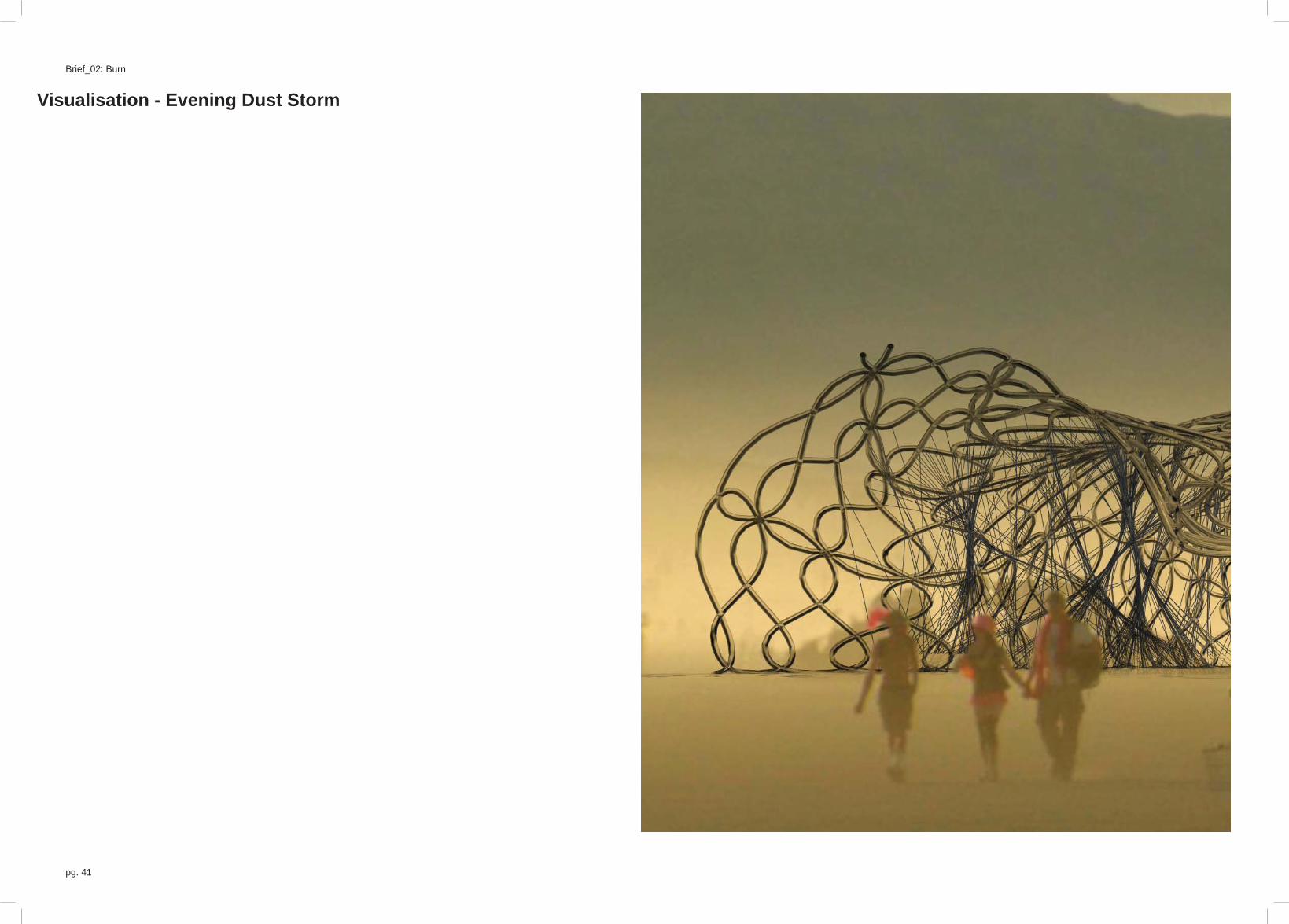
Visualisation - Evening Dust Storm

Michael Clarke pg. 42

pg. 43
Brief_02: Burn Burning Man - Inclusive society
Visualisation - Late Evening HazeThese renders were never fully fi nished although they are included to show the design at this stage of progress. I am beginning to change the overall forms and refi ne the ideas behind the proposal.

Michael Clarke pg. 44

pg. 45
Brief_02: Burn
Visualisation - Night lights

Michael Clarke pg. 46

pg. 47
Brief_02: Burn
Physical Model - Weaving and LightingBased on the initial pattern I set up for weaving across any surface I started to build a physical model to test the structuralimplications as well as the water movement, the fl exible surface and the ability to draw fl ourescent material through the structure at night. From the tests although it does stand up freely it will need a more solid or fi xed foundation. In addition the more levels added the more the pattern loses it’s porosity and begins to sag, the water adds further mass to this effect that would need tobe taken into account in the overall form. I may need to add wire or use the thread networks within to add stiffness or additionaltension members to secure the structure fully. I also need to look further at the design of the tanks for water storage and a pumpmechanism to replace the top reservoir or an evaporative system for the bottom.
The two rows of images are time based sequences from left to right. The top row shows the model growing whereas the bottom row shows the movement of light within the structure.
Sequence 01.
Sequence 02.

Michael Clarke pg. 48

pg. 49
Brief_02: Burn

Michael Clarke pg. 50
Design Development and Final Proposal Refi ning the proposal, further experimentation and researchFinal proposal renders, diagrams, animation and specifi cations including outline costings and the draft submission for the Burning Man arts grant

pg. 51
Brief_02: Burn
ExploreAfter drawing participants in from the approach my structure needs to provide the next level of play and interaction. I have lookedbriefl y into what kind of structure or composition can lead to exploration, what will draw the eye of tease human curiosity. These are just a summary of the kind of design intentions that will help to draw burners into my pavilion to the heart of the structure.
Just around the corner:
The dynamic nature of the curves in contrast with their surroundings draw the eye around a bend. The surroundings: land, a building or an object are very solid and blocks views of what may be around the bend or corner. The effect is much greater if aglimpse of what may be there can be seen before you start around the corner which emerges further as you progress, rewarding your exploration. It works on a similar level without a curved route however, for example exploring the twisting and winding streetsof medieval european cities e.g Rome or the tuscan hilltop villages such as San Gimignano. The key here is the contrast and theconstant turning of the streets, there is always a corner and they are interspersed with large open squares. The contrast is key to this phenomenon on a larger urban scale over individual circumstances.
Glimpses of beyond:
As with around the corner we are encouraged to explore when we can see but not fully understand something just out of our reach.As in a maze where we can begin to see through routes or in a forest where we can glimpse between the trees without seeing the objective or destination itself. This is particularly true in bamboo forests that can be very sparse in places or incredibly dense in others. Bamboo can clump affording places of refuge within screened walls. It can also provide routes between these spaces, offering glimpses of alternative routes and spaces, a scene of hide and seek and races.
Aspirations, curiosity and knowledge:
Humans have an inherent curiosity from a very young age. Part of our development as a child is learning through exploring and questioning. As part of this we always try to fi nd out what we don’t know, even visually. The wall or fence can have so many social and even political connotations however at a very basic and even childish level, it obscures a view. The question is posed, whatlies the other side. There are so many examples of getting a leg up or standing on something to try and see the other side of awall, what is happening or what is there.
Light, contrast and choice:
The analogy of light at the end of a tunnel is known to everyone and to generalise we are all drawn to the light. Light, colour and contrast play a huge part in our moods, feelings and choices. Colour is linked to our feelings, red can be passion or warning, black is often danger, blues are cold etc. Of course there is a whole science to colour affi nities and there are cultural differences in addition. Contrast and brightness also play a part, as with the tunnel humans are often drawn to the brighter areas, these canrepresent activity, life and safety. The fi nal part is choice. Being able to choose a path or direction puts the control in the hands of the person experiencing the space and adds a level of play as with a maze. It means that they are in control of their explorationand as a result are encouraged by their decisions to continue to explore.
<< 01. Around the corner, the curves and the glimpse of a view behind the wall falling away draw the eye and insight a need to explore
02. Bamboo forming in natural clumps, I always enjoyed running between bamboo clumps and the opportunity it afford for refuge. It can be explored and offers unexpected spaces with gaps between the walls allowing you to glimpse the other side
03. Human nature of curiosity shows time and again a desire to see the other side of a wall or fence, we are always curious to view and fi nd out about what we don’t know.
04. Changes in light within a space and specifi cally a brighter light at the end of a route, the light at the end of the tunnel, encourage movement and exploration towards a destination. In addition choice of routes allows the user to control their destination, as in a maze.

Michael Clarke pg. 52

pg. 53
Brief_02: Burn
Catalogue of SpacesFollowing on from my research the fi nal design responds to each need I have identifi ed:
- The Approach - what it looks like from a distance? What draws you near?
- Exploration - something to draw you in further and a childlike play
- The Event - a central space found, where the pavilion comes to life, giving meaning to the structure and the experience
- Refl ection - A more intimate and secluded space to take in the experience and fi nd a calming peace akin to watching a fl ame or the waves
The approach, a rising central tower makes the pavilion stand out from across the playa. At night the water reservoirs held at the top of the spire will glow a series of different fl uorescent dyes as a beacon.
Explore, light moves through the tunnel drawing the visitor down each entrance. The constantly twisting and winding light whose movement in the pipes is only apparent as you get closer to the structure encourages exploration into and through the pavilion.

Michael Clarke pg. 54
The event space starts at the centre of the pavilion. Water is slowly dripped through the pavilion’s pipes from a series of containers at the top of the spire. The light from above is siphoned and pushed through the pipes and even in the day will provide visual interest. This space is a large open space where people who have entered through the tunnels can congregate.
Refl ective spaces come about from the pods surrounding the main space. Burners will be able to weave their way between the water pipes and into smaller spaces big enough for two to three people that are intimate yet open to views of the playa and the stars at night.

pg. 55
Brief_02: Burn
Physical ComponentsFrom a distance the structure can be seen to spiral out of the Playa. A central ‘spire’ comprised of three axis split evenly arounda circle marks it out as a landmark on the Playa and therefore as a destination. These three axis are each made up of 8 solid tubes, spiralling within the element. Two more axis designate entrances/exits to the structure, again made from 8 solid tubes each.These elements are the structural elements of the artwork. The two entrances are to be orientated to face the burning man and the temple, wherever the artwork is to be placed upon the playa. This does not mean that it cannot be approached from other directions and due to the radial nature of the design the experience is not direction specifi c. The entrances are marked out by a tunnel of smaller tubing that carries fl uorescent water during the event. These tunnels of light guide the participant into a central ‘event’ space. This is wrapped in additional tubing in a weaved pattern offering views out whilst enclosing the space. From thecentre of the piece the participant will be able to see how the structure works and watch as water and dyes are added, followingtheir movement around the structure. The water is added towards the top of the central ‘spire’ in a series of tanks constructedfrom upturned 5 litre water bottles lashed to the solid elements. The water tubes that emerge from these are draped over and tiedbetween the solid elements along the main axis.
01.
02.
03.
04.
04.
04.
05.
06.

Michael Clarke pg. 56
01.
02.
04.
03.
05.
06.
<> 01. Concrete fi lled clear PVC tubing provides structural stability for the proposal
02. The water tank (initially empty) is made from 5 gallon water bottles lashed together and hung between the structural columns. This is where the structure is fi lled from each night
03. The event clock - seven pods or rooms formed from a single continuously weaving polypropylene tube. These fi ll up slowly with water over the course of the event with one pod fi lled each night counting the days
04. Further polypropylene tubing split into three segments, this forms the central enclosure whilst allowing views in and out. Each segment will carry separate paths of water
05. Entrance/exit made of a continuously looping polypropylene pipe hung over the concrete support tubes forming a tunnel of water/light that fi lls up over the course of the event, orientated towards the burning man
06. Entrance/exit as 05. however orientated towards the temple

pg. 57
Brief_02: Burn
Water FlowThe water in the structure has two functions although is chiefl y the performance aspect of the pavilion. The other function is the thermal mass capabilities of water to try and cool the space within the pavilion.
The performance is key to the participants experience of the pavilion. Each night a set amount of water is added to the pavilionwith a different coloured fl uorescent dye from the top of the central spire. The water cascades around the tubes weaving over the central space and in addition begins to fi ll up the two entrance tubes and the event clock refl ective spaces. Participants will be able to follow the movement of the water and air bubbles through the tubes in a playful exploration. In addition users will be ableto climb between the tubes into the refl ective spaces to be fully enveloped by the performance.
The dyes are water soluble and can be added to the water in the tank picking and choosing which colours down which routes. UV lighting fi xed to the concrete tubes set off the fl uorescence within the structure.

Michael Clarke pg. 58
<< Water Routes
Central routes envelope the main space in three segments
Two routes form the entrance and exit tunnels from the central space.
A fi nal route runs through each of the seven intimate spaces

pg. 59
Brief_02: Burn
Controlling The Water FlowThe water needs to be constantly added to the structure over the course of the event. For this I need something to regulate thefl ower of water from the tanks at the top of the structure into the pipes so that the pipes don’t overfl ow. I have looked at potentially using IV drip controllers to regulate the fl ow of liquid. This is a simple mechanism that simply pinches the pipes to restrict the fl ow and is variable via sliding the toothed wheel that clamps the pipe along a slope. Although it would be relatively cheap to buythese, they could also be simply manufactured from wood that could be burnt at the end of the festival. Alternatively, these couldbe reusable and clamped to the exterior of the pipes.
As there is a constant fl ow of liquid into the pipes the air already in the pipes will need to have an exit point to allow the water to fi ll the tubes. This cannot be at a lower level than water entered the pipes otherwise the water will simply fl ow out of the system when it reaches the end of the pipe. In addition, the fl ow of water, although added constantly will not move around the structure constantly. Instead it will pool in the pipes low points before fl owing over ‘u-bends’ or being pulled and setting up mini siphons. The pipes internal diameter will also add drag and may need to be increased if the fl ow will not move around the coils. This unknown aspect to the event of the water adds another dimension and added interest for the participants to experience the art.
>> Water fl ow process
01. Water tanks constructed from plastic water bottles turned upside down hold the full amount of water required to fi ll the pavilion
02. Water is released to the pipes that make up the pavilion constantly throughout the event regulated by a drip controller similar to an IV medical drip
03. Water circulates around each of the routes, not necessarily in a predictable manner as the pipes twist and turn causing settling, sudden siphons and air pockets to form
Drip control
This is a very basic section through a drip controller for a standard IV drip. The wheel is free to be adjusted to the left or the right clamping the liquid carrying tube more or less to control the fl ow rate.
clamp wheel
water tube

Michael Clarke pg. 60
04. The end of each pipe needs to be above the point that the water entered to ensure that the air can escape the pipes as the water is forced through and to make sure that the water will not overfl ow at either end

pg. 61
Brief_02: Burn
Structural StabilityThe problem with the main proposal is that the pipes holding the water will not stand up of their own accord. They are too fl exible to be structural even without the addition of the water’s weight. The current model has approximately 815m of polypropylene tubingto carry the water around the structure that needs supporting.
Following the feedback from my end of term crit I have begun to explore the use of concrete as a structural base to support thetubes. I want to maintain the aesthetic of the tubes and the fl uidity of the fi nal form so I began to explore whether fi lling tubes with concrete may be able to provide a solution.
Following a precedent by ecoLogic Studio called Fibrous Room (see fi gure 01) I decided to try samples using different concrete mixes and try some basic load testing on each sample. I then tried to think about scaling this up into a working 1:1 prototype thatcould be prefabricated and transported to site to avoid pouring any concrete on the playa.
02.01.
A CB

Michael Clarke pg. 62
0
1000
2000
3000
4000
5000
6000
7000
8000
9000
10000
11000
12000
13000
14000
15000
-1 0 1 2 3 4 5 6 7 8 9 10 11 12
Load
(N
)
Extension (mm)
Specimen 1 to 3
Specimen LabelSample ASample B (Sand & Cement)Sample C (Sand, Cement + detergent)
>> This experiment created three samples of concrete to test inside identical pVC tubes. The tubes have an internal diameter of 24mm and an outside diameter of 28mm giving a wall thickness of 2mm. The fi rst sample (A) was a traditional concrete mix with 10mm aggregate, sand, cement and water. Sample B removed the aggregate as it is diffi cult to fi ll the tubes with and sample C was the same as sample B but with the addition of liquid detergent to act as a plasticiser to improve the concrete’s workability.
Although the concrete set successfully the subsequent compression loads testing was not so successful. At a certain point after an initial failure the sand cement samples (B and C) just kept compressing tricking the software into the maximum load able to be supported. The triangles on the graph in fi gure 05 supposedly represent the failure point. On observation this was much earlier for B and C, traced back to the fi rst dip in the loading. In addition this does not measure the tension, a key limiting factor of concrete which only really works well in compression and the samples could not be tested in their true performance.03.
04.
05.

pg. 63
Brief_02: Burn
Structural StabilityAs I can’t pump concrete on the playa my structural supports would need to be able to be prefabricated and transported to site.In addition my previous testing of the samples did not work ideally so I need to build a larger prototype to fully test the ability of concrete pipes as a structural solution.
To try and solve the prefabricated problems I decided to split the framework into smaller segments that could be bolted together. This required ends to be fabricated for each pipe work segment. I decided to use rings that could hold multiple pipes and allow the pipes to be rotated for aesthetic reasons. In addition the rings aim to space the concrete pipes apart to allow for minimal impactof a much heavier material in relation to the primary focus of the pavilion - the water pipes.
Unfortunately I have not been able to fully test the component. Whilst the model was setting it fell over before it fully set causingthe concrete to already crack and therefore fail. However, from the process I have already decided this solution, whilst cheap is not the best way forward for my supports. The diffi culties of using concrete as a material at Burning Man, given the leave no trace principles outweigh the potential cost saving. In addition, the process of building the prototype highlighted the diffi culties in fi lling the tubes with concrete. I struggled to evenly fi ll the tubes and have no way of easily ramming or vibrating the concrete. The twisting tubes can not accommodate reinforcement to help the concrete work in tension which for a fl uid and twisting structure is necessary and the weight of the concrete made it very diffi cult to set the components in the desired positions.
This page documents my process and attempts however I will now begin to look at easier, more controllable means of supporting the structure.
<< The prototype was designed to be a potential 1:1 model
The specifi cation and dimensions are as follows:
- Clear PVC tubing x8: 1m length x 28mm diameter
- MDF rings x2: 400mm diameter, 70mm ring width, 8 30mm holes for the pipes and a central hole of 260mm diameter
- rotation angle was adjustable until hung to set to allow for fl exibilty whilst fi lling the pipes
- corks used to bung the pipes to contain the concrete until they could be trimmed once the concrete had set.
02.
01.
03.

Michael Clarke pg. 64
<<
01. Render of the components fi xed together
02. Model of a single structural component before concrete
03. Close up of the mdf rings with cork bungs
04. Concrete ingredients before mixing: aggregate, sand and cement
05. Adding the water to the mix, plasticiser also added at this point
06. 4 of the pipes are fi lled with concrete, already diffi culties are showing in holding the form for it to set and compacting the concrete in the tubes
07. The concrete already failed and cracked before it fully set due to movement in the pipes and fl exibility in the model
04. 05. 06.
07.

pg. 65
Brief_02: Burn
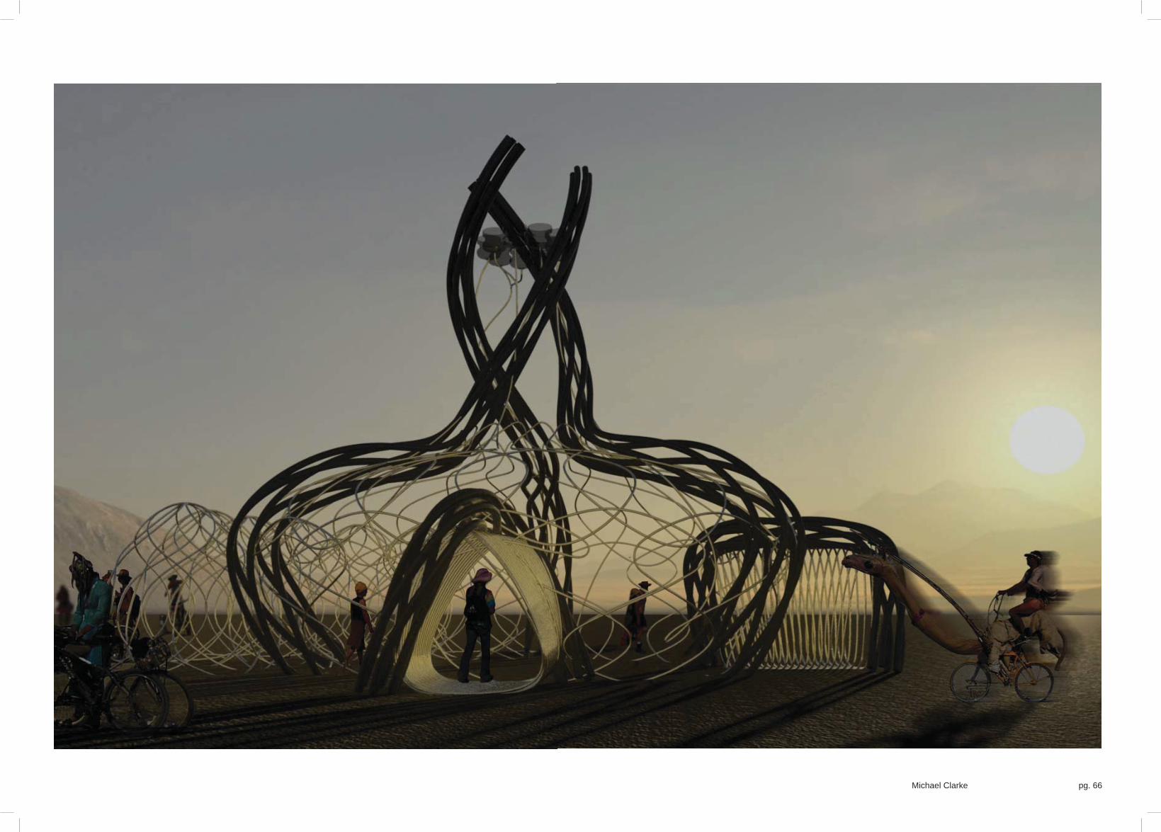
Daytime Render
Michael Clarke pg. 66

pg. 67
Brief_02: Burn
Night-time Render

Michael Clarke pg. 68

pg. 69
Brief_02: Burn
AnimationThe following images represent screenshots from an animation I have put together walking through the structure. Although the fi nal structure may change from this slightly and there will be a lot more pipes this animation gives a clear indication of how thepavilion can be experienced. The animation starts by approaching the structure, and walks into and through it looking around and following the movement of the water. It then exits the structure and quickly fl ies around. The animation, although a slow walkthrough, cycles between the seven days and nights of the festival.
The video can be seen at the unit blog: http://wewanttolearn.net or directly on vimeo: http://vimeo.com/35857649
01. 02. 04.03.
09. 10. 11. 12.
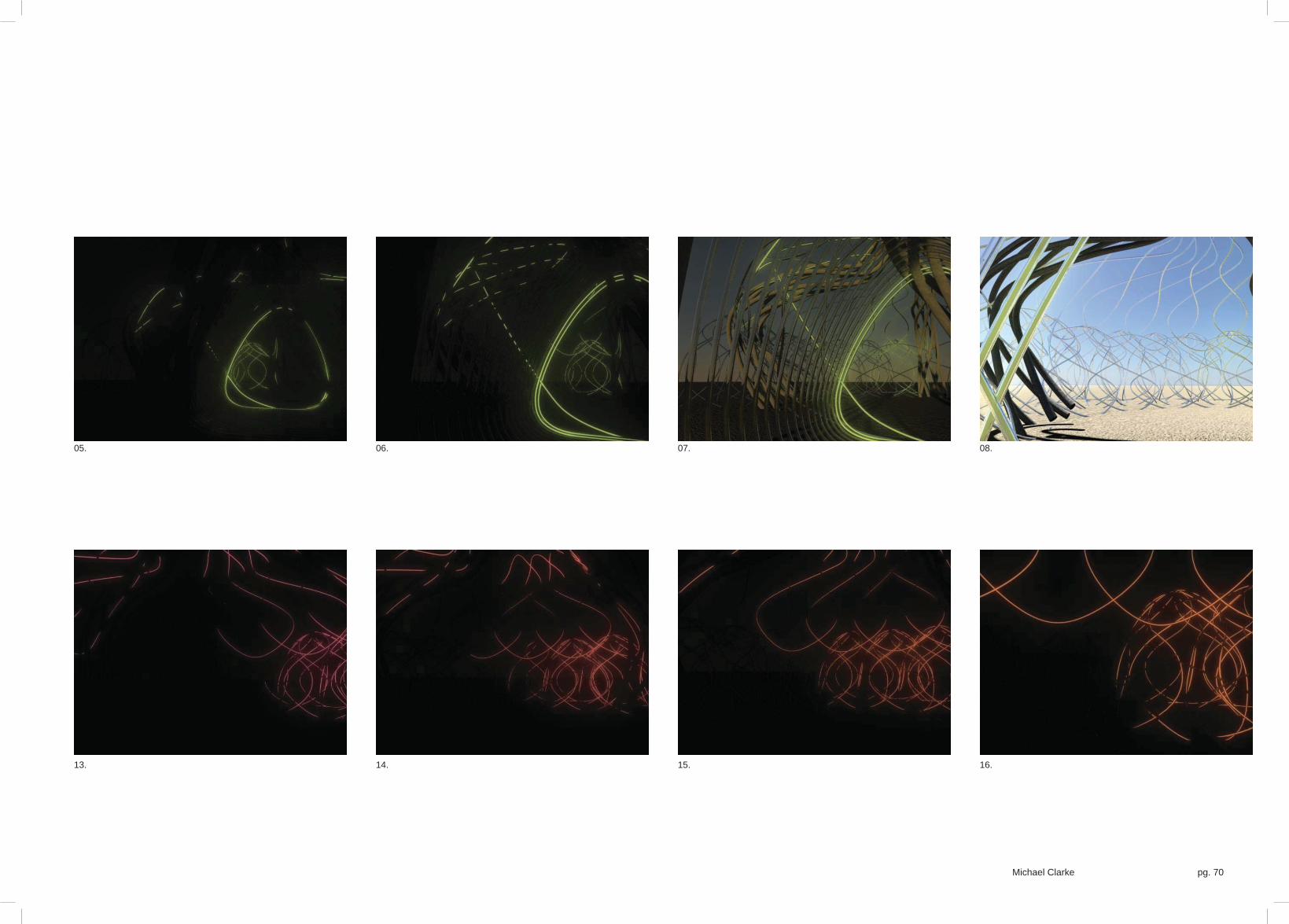
Michael Clarke pg. 70
05. 06. 07. 08.
13. 14. 15. 16.

pg. 71
Brief_02: Burn
Structural Loads and General DimensionsThe problem with the main proposal is that the pipes holding the water will not stand up of their own accord. They are too fl exible to be structural even without the addition of the water’s weight. The current model has approximately 815m of polypropylene tubingto carry the water around the structure that needs supporting.
The weight of the water in addition to the tubes weight is as follows:
Water pipes specifi cation
Imperial: 1/8” ID, 3/16” OD, 1/32” Wall Thickness, 500 available length (feet), weight: 0.85 lbs / 100 ft
Metric: 3.175mm ID, 4.78mm OD, 0.79mm Wall Thickness, 152.4m available length, weight: 0.3855kg/100ft
Weight = 0.3855kg/30.48m = 0.0126kg per metre
Water pipes weight
815m x 0.0126kg = 10.3kg
Weight and volume of water required to fi ll the pipes
Length of pipe x internal area of cross section of pipe = volume of water in cubic metres
815m x (Pi x (0.003175/2)²) = 0.0065m³
1m³ of water weights 1 tonne
0.0065m³ = 6.5kg
1 litre of water weighs one kilogram
therefore: for 815m of pipe I will need 6.5 litres of water and a structure capable of supporting the pipes in addition to 6.5 kg for the weight of the water.
Total weight of the pipes including water = 10.3kg + 6.5kg
= 16.8kg
After the concrete failing I have began to look at using steel. I am currently in conversation with steel fabricators to look at feasible options for the structural work to be built within $15,000 or £10,000.
Probable that the amount of pipework will double over the central structure and the amount of water will increase accordingly.
3 steel sections begin to twist when they reach the centre
1 steel section supports each entrance
Possible need for additional steel framing to the rear of the site
Additional support structure needed to house the water tanks (plastic bottles currently holding 65 litres)

Michael Clarke pg. 72
Bas
e ci
rcle
dia
met
er
Ste
el w
ides
t poi
nt d
iam
eter
Cen
tral t
ower
dia
met
er
3 steel sections equally separated radially by 120°
Each pipe ends rotated through 180° between the start and end of the central tower

pg. 73
Brief_02: Burn
Michael Clarke pg. 74
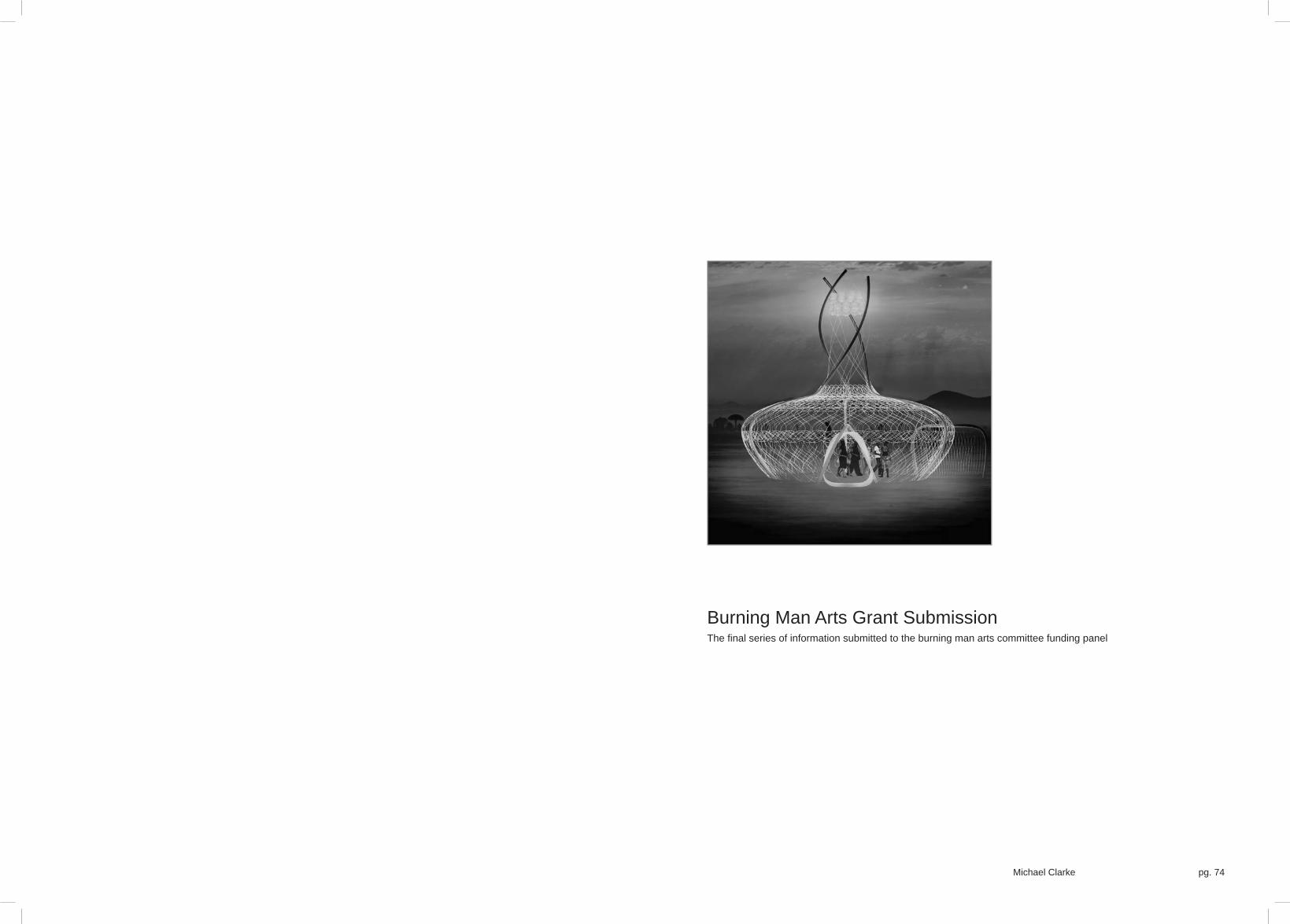
Burning Man Arts Grant SubmissionThe fi nal series of information submitted to the burning man arts committee funding panel

pg. 75
Brief_02: Burn
Michael Clarke
Black LightDay-time Visualisation

Michael Clarke pg. 76

pg. 77
Brief_02: Burn
Michael Clarke
Black LightNight-time Visualisation

Michael Clarke pg. 78

pg. 79
Brief_02: Burn
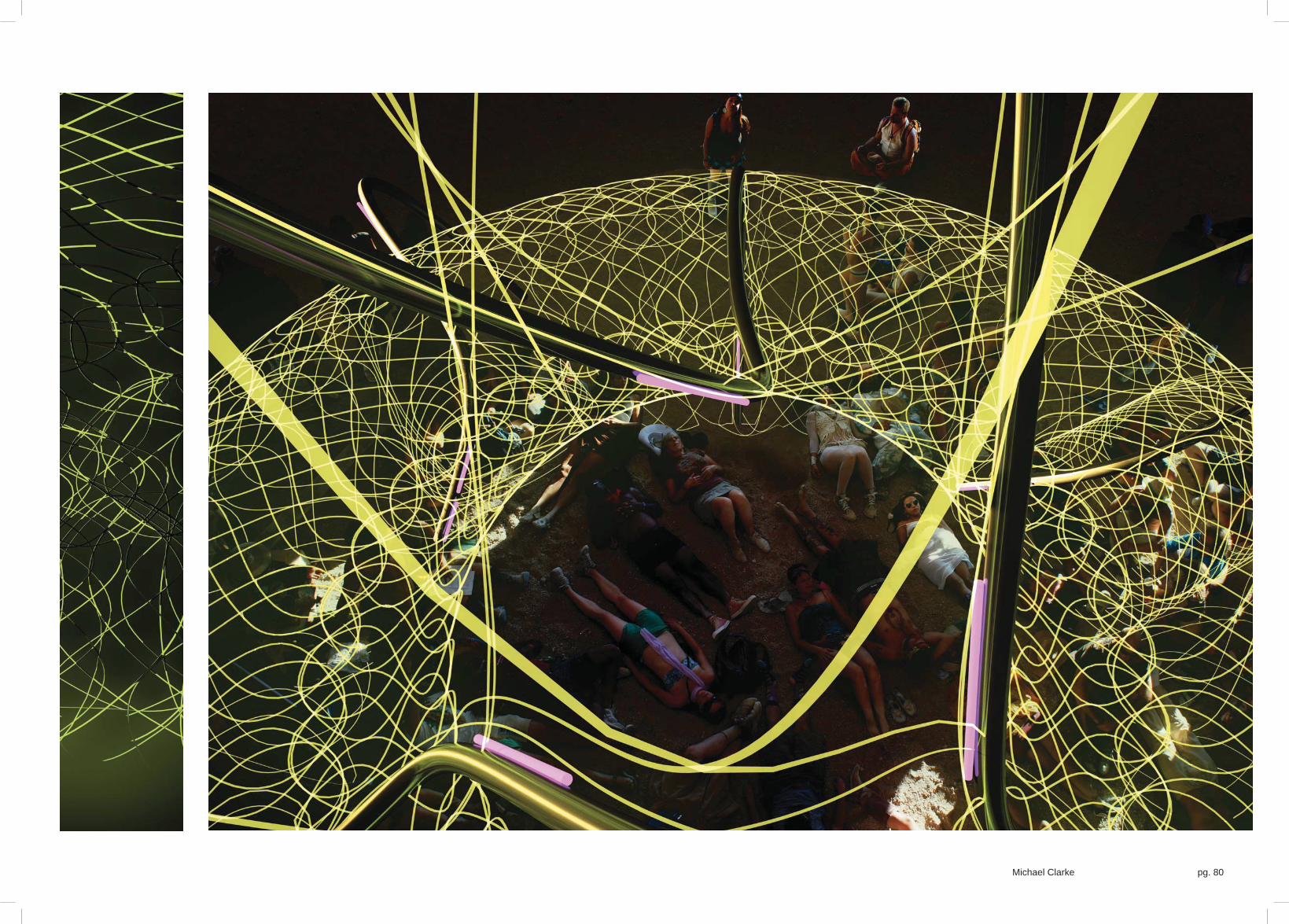
Michael Clarke
Black LightExperiencing the space
Michael Clarke pg. 80

pg. 81
Brief_02: Burn
Michael Clarke
Black LightPhysical ComponentsFrom a distance the structure can be seen to spiral out of the Playa. A central ‘spire’ comprised of three axis split evenly around a circle marks it out as a landmark on the Playa and therefore as a destination. These three axis are each made up of steel tubes, in smaller sections for ease of transportation, bolted together on site. Two more axis designate entrances/exits to the structure, again made from steel elements. These elements are the structural elements of the artwork. The two entrances are to be orientated to face the burning man and the temple, wherever the artwork is to be placed upon the playa. This does not mean that it cannot be approached from other directions and due to the radial nature of the design the experience is not direction specifi c. The entrances are marked out by a tunnel of smaller tubing that carries fl uorescent water during the event. These tunnels of light guide the participant into a central ‘event’ space. This is wrapped in additional tubing in a weaved pattern offering views out whilst enclosingthe space. From the centre of the piece the participant will be able to see how the structure works and watch as water and dyesare added, following their movement around the structure. The water is added towards the top of the central ‘spire’ in a series of tanks constructed from upturned 5 gallon water bottles lashed to the solid elements. The water tubes that emerge from these aredraped over and tied between the solid elements along the main axis.
01.
02.
04.
03.03.
05.
06.
03.

Michael Clarke pg. 82
01.
02.
04.
03.
05.
06.
<> 01. Steel structural elements form stable base for the water tubes
02. The water tank is made from 5 gallon water bottles lashed together and hung between the structural columns.
03. Polypropylene tubing is split into three segments, each one of these split into two networks of tubing. This forms the central enclosure whilst allowing glimpses of views in and out. Each segment will carry separate paths of water
04. Entrance/exit made of a continuously looping polypropylene pipe hung over the steel support tube forming a tunnel of water/light that fi lls up over the course of the event, orientated towards the burning man
05. Entrance/exit as 04. however orientated towards the temple
06. UV strip lights or blacklights fi xed to the steel support elements set of the fl uorescence in the water. This method of fl uorescence ensures that the light remains as bright and emotive on the last day as it started on the fi rst
06.
06.
03.
03.

pg. 83
Brief_02: Burn
3000
1732
Michael Clarke
Black LightStructural Loads, Material quantities and General DimensionsThe problem with the main proposal is that the pipes holding the water will not stand up of their own accord. They are too fl exible to be structural even without the addition of the water’s weight.
The current model has approximately 1705.15m of polypropylene tubing to carry the water around the structure that needs supporting. All calculations work on the basis of 1875m to provide an additional 10% in length for errors on site or the tightness of weave during construction.
The weight of the water in addition to the tubes weight is as follows:
Water pipes specifi cation (these are larger than the initial experiments as siphoning is not being used so to reduce the effect of the surface friction inside the tube the tube diameter has been increased.)
Imperial: 1/4” ID, 3/8” OD, 1/16” Wall Thickness, 50, 100 and 500 available lengths (feet), weight: 3.4 lbs / 100 ft
Metric: 6.35mm ID, 9.52mm OD, 1.6mm Wall Thickness, 15.24m, 30.48m and 152.4m available lengths, weight: 1.5422kg/100ft
Weight = 1.5422kg/30.48m = 0.0506kg per metre
Water pipes weight
1875m x 0.0506kg = 94.875kg
Weight and volume of water required to fi ll the pipes
Length of pipe x internal area of cross section of pipe = volume of water in cubic metres
1875m x (Pi x (0.00635/2)²) = 0.059m³
1m³ of water weights 1 tonne
0.059m³ = 59kg
1 litre of water weighs one kilogram
therefore: for 1875m of pipe I will need 59 litres of water and a structure capable of supporting the pipes in addition to 59 kg for the weight of the water.
Total weight of the pipes including water = 94.875kg + 59kg
= 153.875kg
This means only three water bottles would be necessary to hold the entire water needed for the structure although I am proposingadditional bottles so that the water may be spread out between them and provide a light at the top of the tower. It also means I will need minimal fl uorescent dye due to a small volume of water.
In addition to the tubes and the steel work I need UV lighting. I am proposing 6 UV strip lights on each steel element. These are1200mm long giving a total of 30 UV lights over the structure.
3 steel sections begin to twist when they reach the centre
1 steel section supports each entrance
Additional support structure needed to house the water tanks (plastic bottles currently holding 59 litres)

Michael Clarke pg. 84
7820
2000
Bas
e ci
rcle
dia
met
er
Ste
el w
ides
t poi
nt d
iam
eter
Cen
tral t
ower
dia
met
er
3 steel sections equally separated radially by 120°
Each pipe ends rotated through 180° between the start and end of the central tower

pg. 85
Brief_02: Burn
Michael Clarke
Black LightWater FlowThe water in the structure has two functions although is chiefl y the performance aspect of the pavilion. The other function is the thermal mass capabilities of water to try and cool the space within the pavilion.
The performance is key to the participants experience of the pavilion. Each night a set amount of water is added to the pavilionwith a different coloured fl uorescent dye from the top of the central spire. The water cascades around the tubes weaving over the central space and in addition begins to fi ll up the two entrance tubes and the event clock refl ective spaces. Participants will be able to follow the movement of the water and air bubbles through the tubes in a playful exploration. In addition users will be ableto climb between the tubes into the refl ective spaces to be fully enveloped by the performance.
The dyes are water soluble and can be added to the water in the tank picking and choosing which colours down which routes. UV lighting fi xed to the concrete tubes set off the fl uorescence within the structure.
<<
A conceptual model to illustrate the effects created by the movement of the water and the dye using a glowstick instead of the dye and black light/. Images are in sequence from left to right

Michael Clarke pg. 86
<< Water Routes
Central routes envelope the main space in three segments, each of these has two routes one clockwise and one anti-clockwise
Two routes form the entrance and exit tunnels from the central space.

pg. 87
Brief_02: Burn
Drip control
This is a very basic section through a drip controller for a standard IV drip. The wheel is free to be adjusted to the left or the right clamping the liquid carrying tube more or less to control the fl ow rate.
Michael Clarke
Black LightControlling The Water FlowThe water needs to be constantly added to the structure over the course of the event. For this I need something to regulate the fl ow of water from the tanks at the top of the structure into the pipes so that the pipes don’t overfl ow. I have looked at potentially using IV drip controllers to regulate the fl ow of liquid. This is a simple mechanism that simply pinches the pipes to restrict the fl ow and is variable via sliding the toothed wheel that clamps the pipe along a slope. Although it would be relatively cheap to buy these, theycould also be simply manufactured from wood that could be burnt at the end of the festival. Alternatively, these could be reusableand clamped to the exterior of the pipes.
As there is a constant fl ow of liquid into the pipes the air already in the pipes will need to have an exit point to allow the water to fi ll the tubes. This cannot be at a lower level than water entered the pipes otherwise the water will simply fl ow out of the system when it reaches the end of the pipe. In addition, the fl ow of water, although added constantly will not move around the structure constantly. Instead it will pool in the pipes low points before fl owing over ‘u-bends’ or being pulled and setting up mini siphons. The pipes internal diameter will also add drag and may need to be increased if the fl ow will not move around the coils. This unknown aspect to the event of the water adds another dimension and added interest for the participants to experience the art.
>> Water fl ow process
01. Water tanks constructed from plastic water bottles turned upside down hold the full amount of water required to fi ll the pavilion
02. Water is released to the pipes that make up the pavilion constantly throughout the event regulated by a drip controller similar to an IV medical drip
03. Water circulates around each of the routes, not necessarily in a predictable manner as the pipes twist and turn causing settling, sudden siphons and air pockets to form
clamp wheel
water tube

Michael Clarke pg. 88
04. The end of each pipe needs to be above the point that the water entered to ensure that the air can escape the pipes as the water is forced through and to make sure that the water will not overfl ow at either end