Gradients with Depth in Electrospun Fibrous Scaffolds for...
7
Published: May 02, 2011 r2011 American Chemical Society 2344 dx.doi.org/10.1021/bm200415g | Biomacromolecules 2011, 12, 2344–2350 ARTICLE pubs.acs.org/Biomac Gradients with Depth in Electrospun Fibrous Scaffolds for Directed Cell Behavior Harini G. Sundararaghavan and Jason A. Burdick* Department of Bioengineering, University of Pennsylvania, Philadelphia, Pennsylvania 19104, United States ’ INTRODUCTION Electrospinning has emerged as a versatile, facile way to develop in vivo-like fibrous scaffolds of synthetic and natural materials, with the ability to control material properties (mechanics, adhesion, degradation) independent of fiber size and orientation. 1 5 Although many studies have investigated electrospun scaffolds for a range of tissue engineering applica- tions, few approaches have been successful in creating clinically viable materials that permit cell integration and infiltration. Often, cellular population and tissue formation occur only at the scaffold periphery. 6 Methods that have been previously used to increase cell infiltration include spinning mixed populations of micro and nano-sized fibers, 7 electrospinning in the presence of cells, 8 spinning with sacrifical fibers, 9 including poragens during fiber collection, 9 and photopatterning, 10 all of which have shown some degree of success in increasing initial cell infiltration into the scaffold. However, these methods typically focus on initial scaffold porosity and do not actually direct cells into the scaffold, which can be very important for scaffold integration and vascularization. Directed cell migration is critical during many physiological processes such as tissue development, tumorigenesis, and wound healing and has potential use in several tissue engineering applications, such as tissue vascularization, neurite alignment, and constructs for tissue interfaces. Common approaches to direct cells include gradients of mechanics, adhe- sion and growth factors, and physically through aligned channels and fibers. 11 16 Although growth factors are generally the most influential on cell migration, they are difficult to integrate into tissue engineered scaffolds because both a source and sink for the molecules are necessary. 17,18 Mechanical and adhesive gradients can potentially be included into tissue-engineered constructs, yet the majority of work in this area has been in two dimensions because gradients are difficult to incorporate into 3D scaffolds. Some 3D examples include chemical gradients in agarose, 18 polyethylene glycol (PEG) 19 and collagen 11,20 hydrogels, and mechanical gradients in collagen 11 and PEG 19 hydrogels by modulating cross-linking density. Yet, gradients in fibrous sys- tems have been limited. In fibrous electrospun systems, gradients of materials have been shown in the x y direction, 3 and gradients of nanoparticles 21 have been previously fabricated, but these systems have been limited in their ability to control cell behavior with scaffold depth, including infiltration. Thus, there is a need for systems that can direct cell migration while harnessing the benefits of ECM-like fibrous scaffolds. We have chosen to use hyaluronic acid (HA) for this study because of our ability to manipulate mechanics, adhesion, and degradation within HA gels. 22 24 HA is a naturally found nonadhesive, biocompatible polysaccharide that is made up of alternating D-glucuronic acid and N-acetyl-D-glucosamine and is found in most connective tissues and has been previously used for applica- tions such as bone 25 and neural tissue engineering. 26 HA can be Received: March 26, 2011 Revised: April 29, 2011 ABSTRACT: A major obstacle in creating viable tissue-engi- neered constructs using electrospinning is the lack of complete cellularization and vascularization due to the limited porosity in these densely packed fibrous scaffolds. One potential approach to circumvent this issue is the use of various gradients of chemical and biophysical cues to drive the infiltration of cells into these structures. Toward this goal, this study focused on creating durotactic (mechanical) and haptotactic (adhesive) gradients through the thickness of electrospun hyaluronic acid (HA) scaffolds using a unique, yet simple, modification of common electrospinning protocols. Specifically, both mechanical (via cross-linking: ranging from 27 100% modified methacrylated HA, MeHA) and adhesive (via inclusion of the adhesive peptide RGD: 0 3 mM RGD) gradients were each fabricated by mixing two solutions (one ramping up, one ramping down) prior to electrospinning and fiber collection. Gradient formation was verified by fluorescence microscopy, FTIR, atomic force microscopy, and cellular morphology assessment of scaffolds at different points of collection (i.e., with scaffold thickness). To test further the functionality of gradient scaffolds, chick aortic arch explants were cultured on adhesive gradient scaffolds for 7 days, and low RGD-high RGD gradient scaffolds showed significantly greater cell infiltration compared with high RGD low RGD gradients and uniform high RGD or uniform low RGD control scaffolds. In addition to enhanced infiltration, this approach could be used to fabricate graded tissue structures, such as those that occur at interfaces.
Transcript of Gradients with Depth in Electrospun Fibrous Scaffolds for...
Published: May 02, 2011
r 2011 American Chemical Society 2344 dx.doi.org/10.1021/bm200415g | Biomacromolecules 2011, 12, 2344–2350
ARTICLE
pubs.acs.org/Biomac
Gradients with Depth in Electrospun Fibrous Scaffoldsfor Directed Cell BehaviorHarini G. Sundararaghavan and Jason A. Burdick*
Department of Bioengineering, University of Pennsylvania, Philadelphia, Pennsylvania 19104, United States
’ INTRODUCTION
Electrospinning has emerged as a versatile, facile way todevelop in vivo-like fibrous scaffolds of synthetic and naturalmaterials, with the ability to control material properties(mechanics, adhesion, degradation) independent of fiber sizeand orientation.1�5 Although many studies have investigatedelectrospun scaffolds for a range of tissue engineering applica-tions, few approaches have been successful in creating clinicallyviable materials that permit cell integration and infiltration.Often, cellular population and tissue formation occur only atthe scaffold periphery.6 Methods that have been previously usedto increase cell infiltration include spinning mixed populations ofmicro and nano-sized fibers,7 electrospinning in the presence ofcells,8 spinning with sacrifical fibers,9 including poragens duringfiber collection,9 and photopatterning,10 all of which have shownsome degree of success in increasing initial cell infiltration intothe scaffold. However, these methods typically focus on initialscaffold porosity and do not actually direct cells into the scaffold,which can be very important for scaffold integration andvascularization.
Directed cell migration is critical during many physiologicalprocesses such as tissue development, tumorigenesis, andwound healing and has potential use in several tissueengineering applications, such as tissue vascularization, neuritealignment, and constructs for tissue interfaces. Commonapproaches to direct cells include gradients of mechanics, adhe-sion and growth factors, and physically through aligned channelsand fibers.11�16 Although growth factors are generally the most
influential on cell migration, they are difficult to integrate intotissue engineered scaffolds because both a source and sink for themolecules are necessary.17,18 Mechanical and adhesive gradientscan potentially be included into tissue-engineered constructs, yetthe majority of work in this area has been in two dimensionsbecause gradients are difficult to incorporate into 3D scaffolds.Some 3D examples include chemical gradients in agarose,18
polyethylene glycol (PEG)19 and collagen11,20 hydrogels, andmechanical gradients in collagen11 and PEG19 hydrogels bymodulating cross-linking density. Yet, gradients in fibrous sys-tems have been limited. In fibrous electrospun systems, gradientsof materials have been shown in the x�y direction,3 andgradients of nanoparticles21 have been previously fabricated,but these systems have been limited in their ability to controlcell behavior with scaffold depth, including infiltration.
Thus, there is a need for systems that can direct cell migrationwhile harnessing the benefits of ECM-like fibrous scaffolds. Wehave chosen to use hyaluronic acid (HA) for this study because ofour ability to manipulate mechanics, adhesion, and degradationwithin HA gels.22�24 HA is a naturally found nonadhesive,biocompatible polysaccharide that is made up of alternatingD-glucuronic acid and N-acetyl-D-glucosamine and is found inmost connective tissues and has been previously used for applica-tions such as bone25 and neural tissue engineering.26 HA can be
Received: March 26, 2011Revised: April 29, 2011
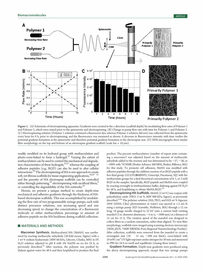
ABSTRACT: A major obstacle in creating viable tissue-engi-neered constructs using electrospinning is the lack of completecellularization and vascularization due to the limited porosity inthese densely packed fibrous scaffolds. One potential approachto circumvent this issue is the use of various gradients ofchemical and biophysical cues to drive the infiltration of cellsinto these structures. Toward this goal, this study focused oncreating durotactic (mechanical) and haptotactic (adhesive)gradients through the thickness of electrospun hyaluronic acid(HA) scaffolds using a unique, yet simple, modification ofcommon electrospinning protocols. Specifically, both mechanical (via cross-linking: ranging from 27�100%modified methacrylatedHA,MeHA) and adhesive (via inclusion of the adhesive peptide RGD: 0�3mMRGD) gradients were each fabricated bymixing twosolutions (one ramping up, one ramping down) prior to electrospinning and fiber collection. Gradient formation was verified byfluorescence microscopy, FTIR, atomic force microscopy, and cellular morphology assessment of scaffolds at different points ofcollection (i.e., with scaffold thickness). To test further the functionality of gradient scaffolds, chick aortic arch explants were culturedon adhesive gradient scaffolds for 7 days, and low RGD-high RGD gradient scaffolds showed significantly greater cell infiltrationcompared with high RGD�low RGD gradients and uniform high RGD or uniform low RGD control scaffolds. In addition toenhanced infiltration, this approach could be used to fabricate graded tissue structures, such as those that occur at interfaces.
2345 dx.doi.org/10.1021/bm200415g |Biomacromolecules 2011, 12, 2344–2350
Biomacromolecules ARTICLE
readily modified on its hydroxyl group with methacrylation andphoto-cross-linked to form a hydrogel.23 Varying the extent ofmethacrylation can be used to control themechanical and degrada-tion characteristics of these hydrogels,23,27 whereas the coupling ofadhesive peptides (e.g., RGD) can also be used to alter cellularinteractions.28The electrospinning ofHA is one approach to createsoft, yet fibrous scaffolds for tissue engineering applications,10,29�31
and the porosity of HA electrospun scaffolds can be controlledeither through patterning,10 electrospinning with sacrificial fibers,9
or controlling the degradability of the HA networks.24
Herein, we present a unique method to create depth-wisemechanical and adhesive gradients through the thickness of HA-based electrospun scaffolds. This was accomplished by modulat-ing the flow rate of two programmable syringe pumps, each withdistinct precursor solutions, one increasing speed and onedecreasing speed, to change the concentration of a fluorescentmolecule or either methacrylation percentage or amount ofadhesive peptide on the HA backbone during scaffold collection.
’MATERIALS AND METHODS
Macromer Synthesis. Methacrylated HA (MeHA) was synthe-sized by reacting methacrylic anhydride (20-fold excess, Sigma) with a1 wt % sodium hyaluronate (MW 66 kDa, Lifecore, Chaska, MN) in DIH2O solution adjusted to pH 8 with 5N NaOH on ice for 24 h, aspreviously described.23 After reaction, the polymer was purified bydialysis against water for 48 h and then lyophilized to produce the final
product. The percent methacrylation (number of repeat units contain-ing a macromer) was adjusted based on the amount of methacrylicanhydride added to the reaction and was determined to be∼27,∼30, or∼100%with 1HNMR (Bruker Advance 360MHz, Bruker, Billerica,MA)for this study. To promote cell adhesion, MeHA was modified withadhesive peptides through the addition reaction of an RGD peptide with afree thiol group (GCGYGRGDSPG, Genscript, Piscataway, NJ) with themethacrylate groups for a final theoretical concentration of 0, 1, or 3 mMRGD in the samples. Specifically, RGD peptide and MeHA were coupledby reacting overnight in triethanolamine buffer, dialyzing against DI H2Ofor 48 h, and lyophilizing to obtain MeHA-RGD.10
Electrospinning HA Scaffolds.MeHA (2 wt %) was cospun withpolyethylene oxide (PEO, 3 wt %, MW 900 kDa, Sigma), as previouslydescribed.4,10 The polymer solution (HA, PEO, and 0.05 wt % Irgacure2959 (I2959, Ciba) photoinitiator in water) was ejected at 1.2 mL/husing a syringe pump (KD Scientific, Holliston, MA) through a 12 cmlong, 18 gauge needle charged to 22 kV onto a custom built rotatingmandrel (2 in. diameter aluminum,∼5m/s,∼1800 rpm) at a distance of15 cm for 15 h. The rotation speed of the mandrel was designed tocollect fibers in a random orientation, rather than aligned. To view fibermorphology, scaffolds were imaged using scanning electron microscopy(SEM, JEOL 7500F HRSEM, Penn Regional Nanotechnology Facility).After collection, scaffolds were removed from the mandrel to create arectangular mat (18 � 15 cm, ∼500 μm thick), cross-linked with10mW/cm2UV light exposure under nitrogen for 30min and immersedin PBS for 24 h to swell and equilibrate (rinsing three times).Gradient Formation. Depth-wise gradients were produced using
the above electrospinning approach, except that two syringe pumps
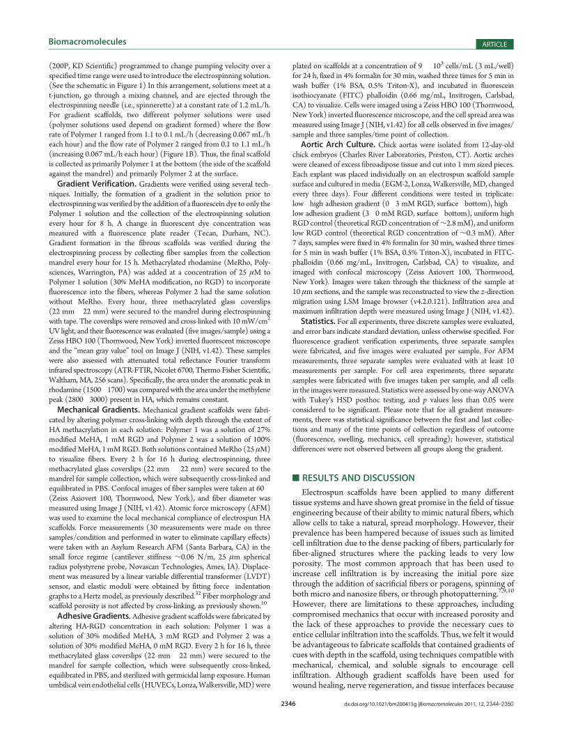
Figure 1. (A) Schematic of electrospinning apparatus. Gradients were created in the z direction (scaffold depth) by modulating flow rates of Polymer 1and Polymer 2, which were mixed prior to the spinnerette and electrospinning. (B) Change in pump flow rate with time for Polymer 1 and Polymer 2.(C) Electrospinning solution (Polymer 1 solution contained a fluorescent dye, whereas Polymer 2 solution did not) was collected from the spinneretteevery hour for 8 h, prior to electrospinning, and the fluorescence was measured as shown. A decrease in fluorescence intensity with time verifies thepotential gradient formation at the spinnerette and therefore potential gradient formation in the electrospun mat. (D) SEM micrographs show similarfiber morphology on the top and bottom of an electrospun gradient scaffold (scale bar = 10 μm).
2346 dx.doi.org/10.1021/bm200415g |Biomacromolecules 2011, 12, 2344–2350
Biomacromolecules ARTICLE
(200P, KD Scientific) programmed to change pumping velocity over aspecified time range were used to introduce the electrospinning solution.(See the schematic in Figure 1) In this arrangement, solutions meet at at-junction, go through a mixing channel, and are ejected through theelectrospinning needle (i.e., spinnerette) at a constant rate of 1.2 mL/h.For gradient scaffolds, two different polymer solutions were used(polymer solutions used depend on gradient formed) where the flowrate of Polymer 1 ranged from 1.1 to 0.1 mL/h (decreasing 0.067 mL/heach hour) and the flow rate of Polymer 2 ranged from 0.1 to 1.1 mL/h(increasing 0.067 mL/h each hour) (Figure 1B). Thus, the final scaffoldis collected as primarily Polymer 1 at the bottom (the side of the scaffoldagainst the mandrel) and primarily Polymer 2 at the surface.Gradient Verification. Gradients were verified using several tech-
niques. Initially, the formation of a gradient in the solution prior toelectrospinningwas verified by the addition of a fluorescein dye to only thePolymer 1 solution and the collection of the electrospinning solutionevery hour for 8 h. A change in fluorescent dye concentration wasmeasured with a fluorescence plate reader (Tecan, Durham, NC).Gradient formation in the fibrous scaffolds was verified during theelectrospinning process by collecting fiber samples from the collectionmandrel every hour for 15 h. Methacrylated rhodamine (MeRho, Poly-sciences, Warrington, PA) was added at a concentration of 25 μM toPolymer 1 solution (30% MeHA modification, no RGD) to incorporatefluorescence into the fibers, whereas Polymer 2 had the same solutionwithout MeRho. Every hour, three methacrylated glass coverslips(22 mm �22 mm) were secured to the mandrel during electrospinningwith tape. The coverslips were removed and cross-linked with 10 mW/cm2
UV light, and their fluorescence was evaluated (five images/sample) using aZeiss HBO 100 (Thornwood, New York) inverted fluorescent microscopeand the “mean gray value” tool on Image J (NIH, v1.42). These sampleswere also assessed with attenuated total reflectance Fourier transforminfrared spectroscopy (ATR-FTIR, Nicolet 6700, Thermo Fisher Scientific,Waltham, MA, 256 scans). Specifically, the area under the aromatic peak inrhodamine (1500�1700) was comparedwith the area under themethylenepeak (2800�3000) present in HA, which remains constant.Mechanical Gradients. Mechanical gradient scaffolds were fabri-
cated by altering polymer cross-linking with depth through the extent ofHA methacrylation in each solution: Polymer 1 was a solution of 27%modified MeHA, 1 mM RGD and Polymer 2 was a solution of 100%modifiedMeHA, 1mMRGD. Both solutions containedMeRho (25 μM)to visualize fibers. Every 2 h for 16 h during electrospinning, threemethacrylated glass coverslips (22 mm � 22 mm) were secured to themandrel for sample collection, which were subsequently cross-linked andequilibrated in PBS. Confocal images of fiber samples were taken at 60�(Zeiss Axiovert 100, Thornwood, New York), and fiber diameter wasmeasured using Image J (NIH, v1.42). Atomic force microscopy (AFM)was used to examine the local mechanical compliance of electrospun HAscaffolds. Force measurements (30 measurements were made on threesamples/condition and performed in water to eliminate capillary effects)were taken with an Asylum Research AFM (Santa Barbara, CA) in thesmall force regime (cantilever stiffness ∼0.06 N/m, 25 μm sphericalradius polystyrene probe, Novascan Technologies, Ames, IA). Displace-ment was measured by a linear variable differential transformer (LVDT)sensor, and elastic moduli were obtained by fitting force�indentationgraphs to a Hertz model, as previously described.32 Fiber morphology andscaffold porosity is not affected by cross-linking, as previously shown.10
Adhesive Gradients. Adhesive gradient scaffolds were fabricated byaltering HA-RGD concentration in each solution: Polymer 1 was asolution of 30% modified MeHA, 3 mM RGD and Polymer 2 was asolution of 30% modified MeHA, 0 mM RGD. Every 2 h for 16 h, threemethacrylated glass coverslips (22 mm �22 mm) were secured to themandrel for sample collection, which were subsequently cross-linked,equilibrated in PBS, and sterilized with germicidal lamp exposure. Humanumbilical vein endothelial cells (HUVECs, Lonza,Walkersville,MD)were
plated on scaffolds at a concentration of 9 � 103 cells/mL (3 mL/well)for 24 h, fixed in 4% formalin for 30 min, washed three times for 5 min inwash buffer (1% BSA, 0.5% Triton-X), and incubated in fluoresceinisothiocyanate (FITC) phalloidin (0.66 mg/mL, Invitrogen, Carlsbad,CA) to visualize. Cells were imaged using a Zeiss HBO 100 (Thornwood,New York) inverted fluorescencemicroscope, and the cell spread area wasmeasured using Image J (NIH, v1.42) for all cells observed in five images/sample and three samples/time point of collection.Aortic Arch Culture. Chick aortas were isolated from 12-day-old
chick embryos (Charles River Laboratories, Preston, CT). Aortic archeswere cleaned of excess fibroadipose tissue and cut into 1 mm sized pieces.Each explant was placed individually on an electrospun scaffold samplesurface and cultured inmedia (EGM-2, Lonza,Walkersville, MD, changedevery three days). Four different conditions were tested in triplicate:low�high adhesion gradient (0�3 mM RGD, surface�bottom), high�low adhesion gradient (3�0 mM RGD, surface�bottom), uniform highRGD control (theoretical RGD concentration of∼2.8mM), and uniformlow RGD control (theoretical RGD concentration of ∼0.3 mM). After7 days, samples were fixed in 4% formalin for 30 min, washed three timesfor 5 min in wash buffer (1% BSA, 0.5% Triton-X), incubated in FITC-phalloidin (0.66 mg/mL, Invitrogen, Carlsbad, CA) to visualize, andimaged with confocal microscopy (Zeiss Axiovert 100, Thornwood,New York). Images were taken through the thickness of the sample at10 μm sections, and the sample was reconstructed to view the z-directionmigration using LSM Image browser (v4.2.0.121). Infiltration area andmaximum infiltration depth were measured using Image J (NIH, v1.42).Statistics. For all experiments, three discrete samples were evaluated,
and error bars indicate standard deviation, unless otherwise specified. Forfluorescence gradient verification experiments, three separate sampleswere fabricated, and five images were evaluated per sample. For AFMmeasurements, three separate samples were evaluated with at least 10measurements per sample. For cell area experiments, three separatesamples were fabricated with five images taken per sample, and all cellsin the imagesweremeasured. Statisticswere assessed by one-wayANOVAwith Tukey’s HSD posthoc testing, and p values less than 0.05 wereconsidered to be significant. Please note that for all gradient measure-ments, there was statistical significance between the first and last collec-tions and many of the time points of collection regardless of outcome(fluorescence, swelling, mechanics, cell spreading); however, statisticaldifferences were not observed between all groups along the gradient.
’RESULTS AND DISCUSSION
Electrospun scaffolds have been applied to many differenttissue systems and have shown great promise in the field of tissueengineering because of their ability to mimic natural fibers, whichallow cells to take a natural, spread morphology. However, theirprevalence has been hampered because of issues such as limitedcell infiltration due to the dense packing of fibers, particularly forfiber-aligned structures where the packing leads to very lowporosity. The most common approach that has been used toincrease cell infiltration is by increasing the initial pore sizethrough the addition of sacrificial fibers or poragens, spinning ofboth micro and nanosize fibers, or through photopatterning.7,9,10
However, there are limitations to these approaches, includingcompromised mechanics that occur with increased porosity andthe lack of these approaches to provide the necessary cues toentice cellular infiltration into the scaffolds. Thus, we felt it wouldbe advantageous to fabricate scaffolds that contained gradients ofcues with depth in the scaffold, using techniques compatible withmechanical, chemical, and soluble signals to encourage cellinfiltration. Although gradient scaffolds have been used forwound healing, nerve regeneration, and tissue interfaces because
2347 dx.doi.org/10.1021/bm200415g |Biomacromolecules 2011, 12, 2344–2350
Biomacromolecules ARTICLE
of their ability to direct cell growth, much of this work wascharacterized in only two dimensions, and there does not appearto have been any techniques developed previously for gradientswith depth in fibrous scaffolds. One previous study has shown theability to create gradients of nanoparticles with depth, which canalso be potentially incorporated in this system.21
Gradient Formation. Thus, a new approach was used tocreate gradient electrospun scaffolds from HA-based materials,where the flow rate of two solutions is altered over the scaffoldcollection period. In our design (Figure 1A), Polymer 1 solutionwas slowly ramped from 1.1 to 0.1 mL/h, and Polymer 2 solutionwas slowly ramped from 0.1 to 1.1 mL/h, prior to meeting at amixing t-junction and ejection through a charged needle forelectrospinning and collection on a rotating mandrel(Figure 1B). With this notation, the solution collects so thatthe bottom of the scaffold (region closest to the mandrel)contains a high concentration of the components of Polymer 1solution, whereas the top of the scaffold contains a highconcentration of the components of Polymer 2 solution. Theflow rate of the solution through the electrospinning needleremains constant at 1.2 mL/h throughout electrospun scaffoldformation, and uniform scaffolds can be fabricated with onepump at this same constant velocity. It should be noted that thereis some imperfection in the gradient formation due to therandomness of fiber collection on the mandrel. Fibers may fallat any location throughout the width of the mandrel duringgradient formation; however, we have used several methods toverify gradient formation throughout the thickness of the scaf-fold. Gradient formation was observed by adding a fluorescentdye to only the Polymer 1 solution and collecting the electro-spinning solution from the spinnerette prior to fiber formation. Adecrease in the concentration of the dye was observed with time,indicating a transition from the solution of Polymer 1 to thesolution of Polymer 2 (Figure 1C). Also, the top and bottom ofthe scaffold was visualized with SEM to verify fiber formation anduniformity throughout the scaffold (Figure 1D).The ability to obtain gradients in the scaffolds was further
verified by creating a fluorescent gradient scaffold where Polymer1 solution contained MeRho (to visualize individual fibers,25 μM) and Polymer 2 solution did not. After collection, the
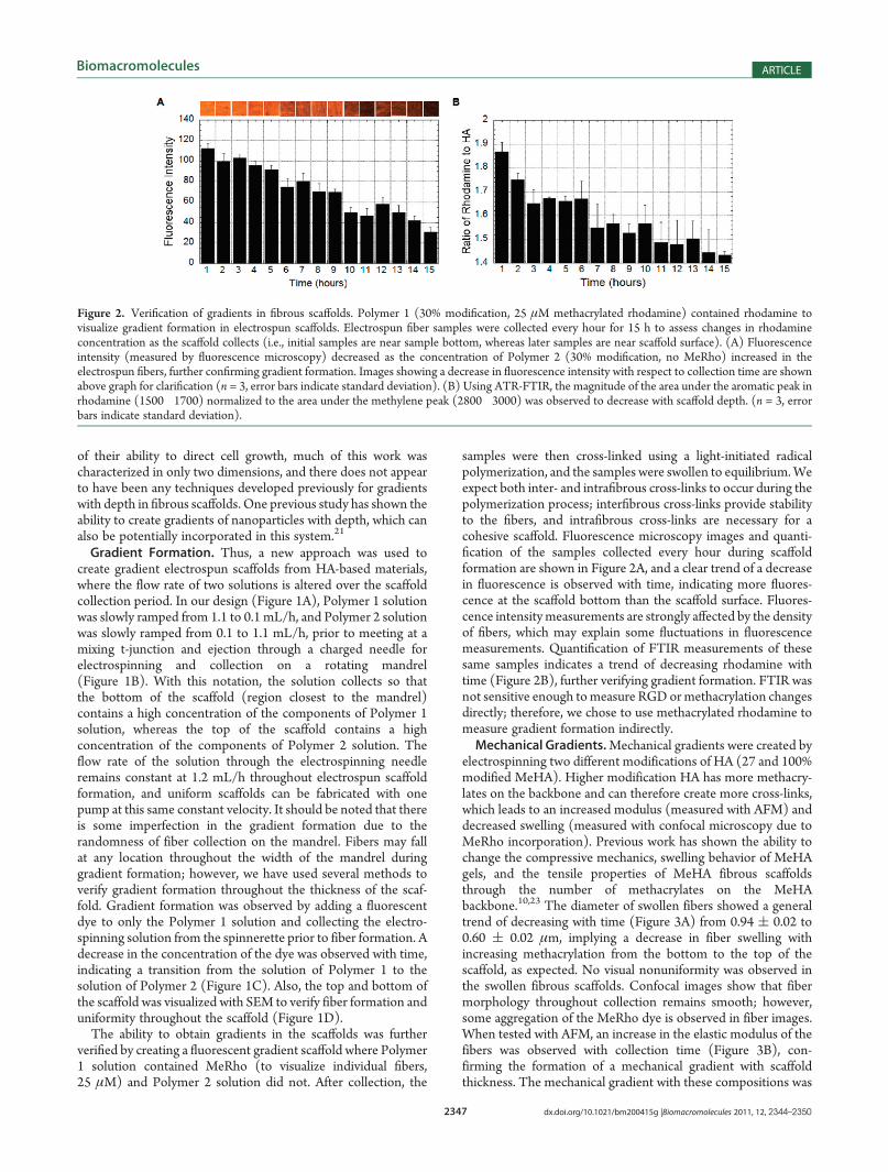
samples were then cross-linked using a light-initiated radicalpolymerization, and the samples were swollen to equilibrium.Weexpect both inter- and intrafibrous cross-links to occur during thepolymerization process; interfibrous cross-links provide stabilityto the fibers, and intrafibrous cross-links are necessary for acohesive scaffold. Fluorescence microscopy images and quanti-fication of the samples collected every hour during scaffoldformation are shown in Figure 2A, and a clear trend of a decreasein fluorescence is observed with time, indicating more fluores-cence at the scaffold bottom than the scaffold surface. Fluores-cence intensitymeasurements are strongly affected by the densityof fibers, which may explain some fluctuations in fluorescencemeasurements. Quantification of FTIR measurements of thesesame samples indicates a trend of decreasing rhodamine withtime (Figure 2B), further verifying gradient formation. FTIR wasnot sensitive enough tomeasure RGDormethacrylation changesdirectly; therefore, we chose to use methacrylated rhodamine tomeasure gradient formation indirectly.Mechanical Gradients.Mechanical gradients were created by
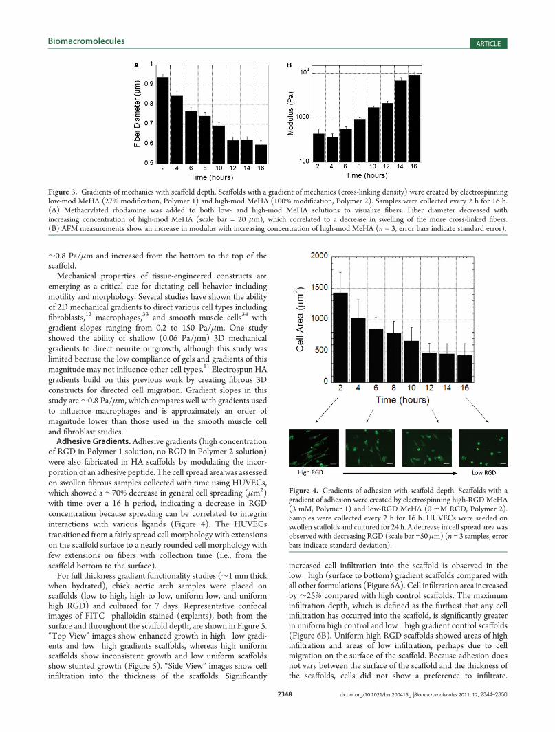
electrospinning two different modifications of HA (27 and 100%modified MeHA). Higher modification HA has more methacry-lates on the backbone and can therefore create more cross-links,which leads to an increased modulus (measured with AFM) anddecreased swelling (measured with confocal microscopy due toMeRho incorporation). Previous work has shown the ability tochange the compressive mechanics, swelling behavior of MeHAgels, and the tensile properties of MeHA fibrous scaffoldsthrough the number of methacrylates on the MeHAbackbone.10,23 The diameter of swollen fibers showed a generaltrend of decreasing with time (Figure 3A) from 0.94 ( 0.02 to0.60 ( 0.02 μm, implying a decrease in fiber swelling withincreasing methacrylation from the bottom to the top of thescaffold, as expected. No visual nonuniformity was observed inthe swollen fibrous scaffolds. Confocal images show that fibermorphology throughout collection remains smooth; however,some aggregation of the MeRho dye is observed in fiber images.When tested with AFM, an increase in the elastic modulus of thefibers was observed with collection time (Figure 3B), con-firming the formation of a mechanical gradient with scaffoldthickness. The mechanical gradient with these compositions was
Figure 2. Verification of gradients in fibrous scaffolds. Polymer 1 (30% modification, 25 μM methacrylated rhodamine) contained rhodamine tovisualize gradient formation in electrospun scaffolds. Electrospun fiber samples were collected every hour for 15 h to assess changes in rhodamineconcentration as the scaffold collects (i.e., initial samples are near sample bottom, whereas later samples are near scaffold surface). (A) Fluorescenceintensity (measured by fluorescence microscopy) decreased as the concentration of Polymer 2 (30% modification, no MeRho) increased in theelectrospun fibers, further confirming gradient formation. Images showing a decrease in fluorescence intensity with respect to collection time are shownabove graph for clarification (n = 3, error bars indicate standard deviation). (B) Using ATR-FTIR, the magnitude of the area under the aromatic peak inrhodamine (1500�1700) normalized to the area under the methylene peak (2800�3000) was observed to decrease with scaffold depth. (n = 3, errorbars indicate standard deviation).
2348 dx.doi.org/10.1021/bm200415g |Biomacromolecules 2011, 12, 2344–2350
Biomacromolecules ARTICLE
∼0.8 Pa/μm and increased from the bottom to the top of thescaffold.Mechanical properties of tissue-engineered constructs are
emerging as a critical cue for dictating cell behavior includingmotility and morphology. Several studies have shown the abilityof 2D mechanical gradients to direct various cell types includingfibroblasts,12 macrophages,33 and smooth muscle cells34 withgradient slopes ranging from 0.2 to 150 Pa/μm. One studyshowed the ability of shallow (0.06 Pa/μm) 3D mechanicalgradients to direct neurite outgrowth, although this study waslimited because the low compliance of gels and gradients of thismagnitude may not influence other cell types.11 Electrospun HAgradients build on this previous work by creating fibrous 3Dconstructs for directed cell migration. Gradient slopes in thisstudy are∼0.8 Pa/μm, which compares well with gradients usedto influence macrophages and is approximately an order ofmagnitude lower than those used in the smooth muscle celland fibroblast studies.Adhesive Gradients. Adhesive gradients (high concentration
of RGD in Polymer 1 solution, no RGD in Polymer 2 solution)were also fabricated in HA scaffolds by modulating the incor-poration of an adhesive peptide. The cell spread area was assessedon swollen fibrous samples collected with time using HUVECs,which showed a ∼70% decrease in general cell spreading (μm2)with time over a 16 h period, indicating a decrease in RGDconcentration because spreading can be correlated to integrininteractions with various ligands (Figure 4). The HUVECstransitioned from a fairly spread cell morphology with extensionson the scaffold surface to a nearly rounded cell morphology withfew extensions on fibers with collection time (i.e., from thescaffold bottom to the surface).For full thickness gradient functionality studies (∼1 mm thick
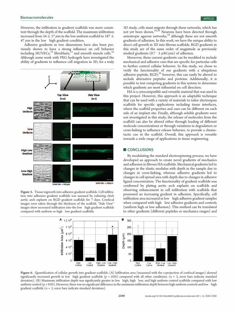
when hydrated), chick aortic arch samples were placed onscaffolds (low to high, high to low, uniform low, and uniformhigh RGD) and cultured for 7 days. Representative confocalimages of FITC�phalloidin stained (explants), both from thesurface and throughout the scaffold depth, are shown in Figure 5.“Top View” images show enhanced growth in high�low gradi-ents and low�high gradients scaffolds, whereas high uniformscaffolds show inconsistent growth and low uniform scaffoldsshow stunted growth (Figure 5). “Side View” images show cellinfiltration into the thickness of the scaffolds. Significantly
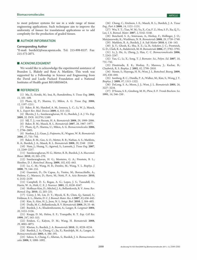
increased cell infiltration into the scaffold is observed in thelow�high (surface to bottom) gradient scaffolds compared withall other formulations (Figure 6A). Cell infiltration area increasedby ∼25% compared with high control scaffolds. The maximuminfiltration depth, which is defined as the furthest that any cellinfiltration has occurred into the scaffold, is significantly greaterin uniform high control and low�high gradient control scaffolds(Figure 6B). Uniform high RGD scaffolds showed areas of highinfiltration and areas of low infiltration, perhaps due to cellmigration on the surface of the scaffold. Because adhesion doesnot vary between the surface of the scaffold and the thickness ofthe scaffolds, cells did not show a preference to infiltrate.
Figure 3. Gradients of mechanics with scaffold depth. Scaffolds with a gradient of mechanics (cross-linking density) were created by electrospinninglow-mod MeHA (27% modification, Polymer 1) and high-mod MeHA (100% modification, Polymer 2). Samples were collected every 2 h for 16 h.(A) Methacrylated rhodamine was added to both low- and high-mod MeHA solutions to visualize fibers. Fiber diameter decreased withincreasing concentration of high-mod MeHA (scale bar = 20 μm), which correlated to a decrease in swelling of the more cross-linked fibers.(B) AFM measurements show an increase in modulus with increasing concentration of high-mod MeHA (n = 3, error bars indicate standard error).
Figure 4. Gradients of adhesion with scaffold depth. Scaffolds with agradient of adhesion were created by electrospinning high-RGDMeHA(3 mM, Polymer 1) and low-RGD MeHA (0 mM RGD, Polymer 2).Samples were collected every 2 h for 16 h. HUVECs were seeded onswollen scaffolds and cultured for 24 h. A decrease in cell spread area wasobserved with decreasing RGD (scale bar =50 μm) (n = 3 samples, errorbars indicate standard deviation).
2349 dx.doi.org/10.1021/bm200415g |Biomacromolecules 2011, 12, 2344–2350
Biomacromolecules ARTICLE
However, the infiltration in gradient scaffolds was more consis-tent through the depth of the scaffold. The maximum infiltrationincreased from 34( 17 μm in the low uniform scaffold to 187(47 μm in the low�high gradient condition.Adhesive gradients in two dimensions have also been pre-
viously shown to have a strong influence on cell behaviorincluding HUVECs,19 fibroblasts,13 and smooth muscle cells.35
Although some work with PEG hydrogels have investigated theability of gradients to influence cell migration in 3D, for a truly
3D study, cells must migrate through these networks, which hasnot yet been shown.19,35 Neurons have been directed throughanisotropic agarose networks,18 although these are not smoothgradients of adhesion. In this work, we have the unique ability todirect cell growth in 3D into fibrous scaffolds. RGD gradients inthis study are of the same order of magnitude as previouslystudied gradients (0.7�5 μM/μm) of adhesion.Moreover, these current gradients can be modified to include
mechanical and adhesive cues that are specific for particular cellsto further control cellular behavior. In this study, we chose toverify the functionality of our gradients with a ubiquitousadhesive peptide, RGD;36 however, this can easily be altered toinclude alternative peptides and proteins. Additionally, it ispossible to test competing gradients in this system to determinewhich gradients are most influential on cell direction.HA is a cytocompatible and versatile material that was used in
this project. However, this approach is an adaptable techniquethat can be used with a variety of materials to tailor electrospunscaffolds for specific applications including tissue interfaces,where the scaffold properties and cues can be different on eachside of an implant site. Finally, although soluble gradients werenot investigated in this study, the release of molecules from thescaffold can also be altered either through loading of differentmolecule concentrations or through variations in degradation orcross-linking to influence release behavior, to provide a chemo-tactic cue in the scaffold. Overall, this approach is versatiletowards a wide range of applications in tissue engineering.
’CONCLUSIONS
By modulating the standard electrospinning process, we havedeveloped an approach to create novel gradients of mechanicsand adhesion in fibrousHA scaffolds. Mechanical gradients led tochanges in the elastic modulus with depth in the sample due tochanges in cross-linking, whereas adhesive gradients led tochanges in cell spread area with depth due to changes in adhesiveligand concentration. The functionality of gradient scaffolds wasconfirmed by plating aortic arch explants on scaffolds andobserving enhancement in cell infiltration with scaffolds thatpossessed an increasing gradient in adhesion. Specifically, cellinfiltration area increased in low�high adhesive gradient sampleswhen compared with high�low adhesive gradients and controls(uniform high or low adhesion). This method can be translatedto other gradients (different peptides or mechanics ranges) and
Figure 6. Quantification of cellular growth into gradient scaffolds. (A) Infiltration area (measured with the z-projection of confocal images) showedsignificantly increased growth in low�high gradient scaffolds (p < 0.05) compared with all other conditions. (n = 3, error bars indicate standarddeviation). (B) Maximum infiltration depth was significantly greater in low�high, high�low, and high uniform control scaffolds compared with lowuniform control (p< 0.05). However, there was no significant difference in themaximum infiltration depth between high uniform controls and low�highgradient scaffolds (n = 3, error bars indicate standard deviation).
Figure 5. Tissue ingrowth into adhesive gradient scaffolds. Cell infiltra-tion into adhesion gradient scaffolds was assessed by culturing chickaortic arch explants on RGD gradient scaffolds for 7 days. Confocalimages were taken through the thickness of the scaffold. “Side View”images show increased infiltration into the low�high gradient scaffoldscompared with uniform or high�low gradient scaffolds.
2350 dx.doi.org/10.1021/bm200415g |Biomacromolecules 2011, 12, 2344–2350
Biomacromolecules ARTICLE
to most polymer systems for use in a wide range of tissueengineering applications. Such techniques aim to improve theuniformity of tissues for translational applications or to addcomplexity for the production of graded tissues.
’AUTHOR INFORMATION
Corresponding Author*E-mail: [email protected]. Tel: 215-898-8537. Fax:215-573-2071.
’ACKNOWLEDGMENT
We would like to acknowledge the experimental assistance ofBrandon L. Blakely and Ross A. Marklein. This work wassupported by a Fellowship in Science and Engineering fromthe David and Lucile Packard Foundation and a NationalInstitutes of Health grant R01AR056624.
’REFERENCES
(1) Ma, Z.; Kotaki, M.; Inai, R.; Ramakrishna, S. Tissue Eng. 2005,11, 101–109.(2) Pham, Q. P.; Sharma, U.; Mikos, A. G. Tissue Eng. 2006,
12, 1197–1211.(3) Baker, B. M.; Handorf, A. M.; Ionescu, L. C.; Li, W. J.; Mauck,
R. L. Expert Rev. Med. Devices 2009, 6, 515–532.(4) Ifkovits, J. L.; Sundararaghavan, H. G.; Burdick, J. A. J. Vis. Exp.
2009, 32. DOI: 10.3791/1589.(5) Sill, T. J.; von Recum, H. A. Biomaterials 2008, 29, 1989–2006.(6) Baker, B. M.; Mauck, R. L. Biomaterials 2007, 28, 1967–1977.(7) Pham, Q. P.; Sharma, U.; Mikos, A. G. Biomacromolecules 2006,
7, 2796–2805.(8) Stankus, J. J.; Guan, J.; Fujimoto, K.; Wagner, W. R. Biomaterials
2006, 27, 735–744.(9) Baker, B. M.; Gee, A. O.; Metter, R. B.; Nathan, A. S.; Marklein,
R. A.; Burdick, J. A.; Mauck, R. L. Biomaterials 2008, 29, 2348�2358.(10) Nam, J.; Huang, Y.; Agarwal, S.; Lannutti, J. Tissue Eng. 2007,
13, 2249–2257.(11) Sundararaghavan, H. G.; Metter, R. B.; Burdick, J. A.Macromol.
Biosci. 2010, 10, 265–270.(12) Sundararaghavan, H. G.; Monteiro, G. A.; Firestein, B. L.;
Shreiber, D. I. Biotechnol. Bioeng. 2009, 102, 632–643.(13) Lo, C. M.; Wang, H. B.; Dembo, M.; Wang, Y. L. Biophys. J.
2000, 79, 144–152.(14) Guarnieri, D.; De Capua, A.; Ventre, M.; Borzacchiello, A.;
Pedone, C.; Marasco, D.; Ruvo, M.; Netti, P. A. Acta Biomater. 2010,6, 2532–2539.(15) Campbell, D. S.; Regan, A. G.; Lopez, J. S.; Tannahill, D.;
Harris, W. A.; Holt, C. E. J. Neurosci. 2001, 21, 8538–8547.(16) Hoffman-Kim, D.; Mitchel, J. A.; Bellamkonda, R. V. Annu. Rev.
Biomed. Eng. 2010, 12, 203–231.(17) Corey, J. M.; Lin, D. Y.; Mycek, K. B.; Chen, Q.; Samuel, S.;
Feldman, E. L.; Martin, D. C. J. Biomed. Mater. Res. A 2007, 83, 636–645.(18) Kim, S.; Kim, H. J.; Jeon, N. L. Integr. Biol. 2010, 2, 584–603.(19) Dodla, M. C.; Bellamkonda, R. V. Biomaterials 2008, 29, 33–46.(20) Burdick, J. A.; Khademhosseini, A.; Langer, R. Langmuir 2004,
20, 5153–5156.(21) Knapp, D. M.; Helou, E. F.; Tranquillo, R. T. Exp. Cell Res.
1999, 247, 543–553.(22) Erisken, C.; Kalyon, D. M.; Wang, H. Biomaterials 2008,
29, 4065–4073.(23) Khetan, S.; Burdick, J. A. Biomaterials 2010, 31, 8228–8234.(24) Burdick, J. A.; Chung, C.; Jia, X.; Randolph, M. A.; Langer, R.
Biomacromolecules 2005, 6, 386–391.(25) Sahoo, S.; Chung, C.; Khetan, S.; Burdick, J. A. Biomacromole-
cules 2008, 9, 1088–1092.
(26) Chung, C.; Erickson, I. E.; Mauck, R. L.; Burdick, J. A. TissueEng., Part A 2008, 14, 1121–1131.
(27) Wei, Y. T.; Tian, W. M.; Yu, X.; Cui, F. Z.; Hou, S. P.; Xu, Q. Y.;Lee, I. S. Biomed. Mater. 2007, 2, S142–S146.
(28) Bencherif, S. A.; Srinivasan, A.; Horkay, F.; Hollinger, J. O.;Matyjaszewski, K.; Washburn, N. R. Biomaterials 2008, 29, 1739–1749.
(29) Marklein, R. A.; Burdick, J. A. Soft Matter 2010, 6, 136–143.(30) Ji, Y.; Ghosh, K.; Shu, X. Z.; Li, B.; Sokolov, J. C.; Prestwich,
G. D.; Clark, R. A.; Rafailovich, M. H. Biomaterials 2006, 27, 3782–3792.(31) Li, J.; He, A.; Zheng, J.; Han, C. C. Biomacromolecules 2006,
7, 2243–2247.(32) Yao, C.; Li, X.; Song, T. J. Biomater. Sci., Polym. Ed. 2007, 18,
731–742.(33) Dimitriadis, E. K.; Horkay, F.; Maresca, J.; Kachar, B.;
Chadwick, R. S. Biophys. J. 2002, 82, 2798–2810.(34) Nemir, S.; Hayenga, H. N.; West, J. L. Biotechnol. Bioeng. 2009,
105, 636–644.(35) Isenberg, B. C.; Dimilla, P. A.; Walker, M.; Kim, S.; Wong, J. Y.
Biophys. J. 2009, 97, 1313–1322.(36) DeLong, S. A.; Moon, J. J.; West, J. L. Biomaterials 2005, 26,
3227–3234.(37) D’Souza, S. E.; Ginsberg, M. H.; Plow, E. F. Trends Biochem. Sci.
1991, 16, 246–250 .