GRADE 12 NATIONAL SENIOR CERTIFICATE GRADE 12… · · 2017-10-05the ratio of the tensile force...
44
Copyright reserved Please turn over MARKS: 200 TIME: 3 hours This question paper consists of 21 pages and a 5-page formula sheet. GRADE 12 MECHANICAL TECHNOLOGY NOVEMBER 2010 NATIONAL SENIOR CERTIFICATE GRADE 12
Transcript of GRADE 12 NATIONAL SENIOR CERTIFICATE GRADE 12… · · 2017-10-05the ratio of the tensile force...

Copyright reserved Please turn over
MARKS: 200 TIME: 3 hours
This question paper consists of 21 pages and a 5-page formula sheet.
GRADE 12
MECHANICAL TECHNOLOGY
NOVEMBER 2010
NATIONAL SENIOR CERTIFICATE
GRADE 12

Mechanical Technology 2 DBE/November 2010 NSC
Copyright reserved Please turn over
INSTRUCTIONS AND INFORMATION 1. Answer ALL the questions. 2. Read ALL the questions carefully. 3. Number the answers correctly according to the numbering system
used in this question paper.
5. Show ALL calculations and units. Round off all final answers to TWO
decimal places.
6. Candidates may use non-programmable scientific calculators and
drawing instruments.
7. The value of gravitational force should be taken as 10 m/s2. 8. Start EACH question on a NEW page. 9. All dimensions are in millimetres unless stated otherwise in the
question.
10. Write neatly and legibly. 11. Use the criteria below to assist you in managing your time.
4. A formula sheet is attached to this paper.
QUESTION ASSESSMENT STANDARD(S) CONTENT MARKS TIME
1 1 – 9 Multiple-choice questions 20 18 minutes
2 6 and 8 Forces, Systems and Control 50 45 minutes
3 2 Tools and Equipment 20 18 minutes
4 3 Materials 20 18 minutes
5 1, 4 and 5 Safety, Terminology and Joining Methods 50 45 minutes
6 7 and 9 Maintenance and Turbines 40 36 minutes
TOTAL 200 180 minutes

Mechanical Technology 3 DBE/November 2010 NSC
Copyright reserved Please turn over
QUESTION 1: MULTIPLE-CHOICE QUESTIONS Various options are provided as possible answers to the following questions. Choose the answer and write only the letter (A – D) next to the question number (1.1 – 1.20) in the ANSWER BOOK.
1.1 Which of the following safety measures apply to a torsion tester?
A
B C D
Make sure the work piece is properly tightened. Be careful of metal particles coming off after the metal fractures. Do not hold the test piece with your hands as it may be hot. All the above-mentioned
(1) 1.2 Which ONE of the following safety procedures does NOT relate to the
coil-spring compressor?
A
B C D
Make sure that the spring clamp does not slip. Compress the spring to remove the shock absorber from the suspension. Use wire or rope to compress the coil spring. Make sure that the coil spring compressor is in a good working condition.
(1) 1.3 What is determined by a cylinder leakage test? A
B C D
Leaking carburettor Leaking cylinder sleeve or engine block Leaking fuel pump Leaking water pump
(1)
1.4 The main reason for a high carbon monoxide reading when using a gas
analyser is …
A
B C D
low compression. worn valves. worn piston rings. a clogged air filter.
(1)

Mechanical Technology 4 DBE/November 2010 NSC
Copyright reserved Please turn over
1.5 Anele has to solder a bronze pipe fitting. What step of the soldering
process does FIGURE 1.1 below show?
FIGURE 1.1 A
B C D
Apply flux to the cleaned surface. Allow the joint to cool. Heat the joint and apply solder to the joint. Clean the surface to be joined with steel wool or emery cloth.
(1)
1.7 Identify the type of milling cutter shown in FIGURE 1.2 below.
FIGURE 1.2 A
B C D
Equal angle cutter Convex cutter Cylindrical/Helical cutter Single corner rounding cutter
(1)
1.6 Thermoplastics are materials that …
A B C D
can be stretched but rapidly return to their original shape. soften under heat and become hard when cooled. form a rigid shape under pressure or heat. is used to manufacture bicycle frames.
(1)
pipe fitting

Mechanical Technology 5 DBE/November 2010 NSC
Copyright reserved Please turn over
1.8 Which lathe operation is shown in FIGURE 1.3 below?
FIGURE 1.3 A
B C D
Diameter turning Facing off Thread cutting Boring
(1) 1.9 What are the disadvantages of downcut milling? A
B C D
A slow cutting feed must be used. Vibration in the arbor is unavoidable. Materials with hard scale damage the cutter teeth. All the above-mentioned
(1) 1.10 What is the reason for using the nick-break test? A
B C D
To test the skill of the welder To check for internal defects To train welders To approve welds to certain standards
(1) 1.11 What are the advantages of gang milling? A
B C D
Less friction of teeth in contact Less grinding is needed to sharpen teeth Less chattering than when using fine tooth cutters All the above-mentioned
(1) 1.12 Stress can be defined or described as an internal force in a material
resisting …
A
B C D
a shearing load. a pulling/tensile load. a pushing/compressive load. any load.
(1)
Mechanical Technology 6 DBE/November 2010 NSC
Copyright reserved Please turn over
1.13 What is understood by the term strain? A
B C D
Force value required to produce unit area in a tensile specimen A measurement for the extension or contraction of material due to the load Stress value required to produce unit strain in a tensile specimen A ratio of the deformation by application of an external force
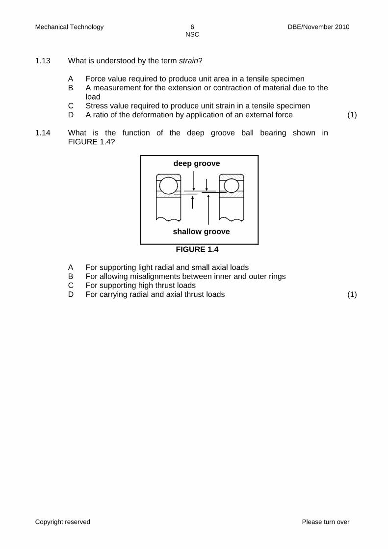
(1) 1.14 What is the function of the deep groove ball bearing shown in
FIGURE 1.4?
FIGURE 1.4 A
B C D
For supporting light radial and small axial loads For allowing misalignments between inner and outer rings For supporting high thrust loads For carrying radial and axial thrust loads
(1)
deep groove
shallow groove

Mechanical Technology 7 DBE/November 2010 NSC
Copyright reserved Please turn over
1.15 Which steps are the most suitable when replacing a roller chain on a chain
drive system as shown in FIGURE 1.5 below?
FIGURE 1.5 A
B C D
Measure the chain length Dismantle the chain Install and join the new chain All the above-mentioned
(1)
roller-link plates
roller link
pin link
pin-link plates
rollers
bushes
pins
one complete link

Mechanical Technology 8 DBE/November 2010 NSC
Copyright reserved Please turn over
1.16 The pulley system shown in FIGURE 1.6 below is …
FIGURE 1.6 A
B C D
changing direction. multiplying force. multiplying distance. All the above-mentioned
(1) 1.17 FIGURE 1.7 shows a single-start nut and bolt. For each complete rotation
of the thread, the nut would move a distance of …
FIGURE 1.7 A
B C D
2 mm. 1 mm. 3 mm. 4 mm.
(1)
load
force
one revolution
pitch = 1 mm
linear movement
Mechanical Technology 9 DBE/November 2010 NSC
Copyright reserved Please turn over
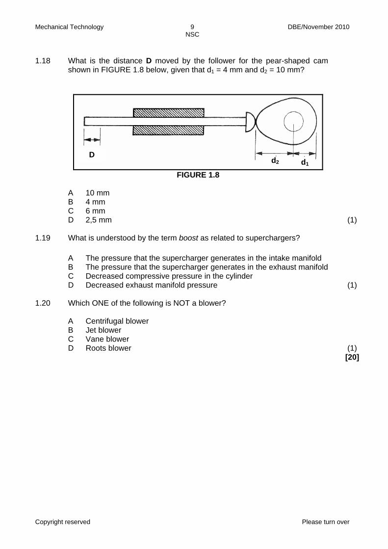
1.18 What is the distance D moved by the follower for the pear-shaped cam
shown in FIGURE 1.8 below, given that d1 = 4 mm and d2 = 10 mm?
FIGURE 1.8
A B C D
10 mm 4 mm 6 mm 2,5 mm
(1) 1.19 What is understood by the term boost as related to superchargers? A
B C D
The pressure that the supercharger generates in the intake manifold The pressure that the supercharger generates in the exhaust manifoldDecreased compressive pressure in the cylinder Decreased exhaust manifold pressure
(1) 1.20 Which ONE of the following is NOT a blower? A
B C D
Centrifugal blower Jet blower Vane blower Roots blower
(1) [20]
D d2 d1

Mechanical Technology 10 DBE/November 2010 NSC
Copyright reserved Please turn over
QUESTION 2: FORCES, SYSTEMS AND CONTROL 2.1 A lever-controlled hydraulic system, with specifications, is shown
diagrammatically in FIGURE 2.1 below.
FIGURE 2.1 Determine, by means of calculations, the following: 2.1.1 The fluid pressure in the hydraulic system in MPa (4) 2.1.2 The force that must be exerted onto PISTON A to lift the load
(150 kN) on PISTON B. (Hint: Use the answer to QUESTION 2.1.1.) Give the answer in kN.
(4) 2.1.3 The force F that must be exerted onto the lever to lift the load of
150 kN on PISTON B. (Give the answers in N.)
(4)
480 mm
80 mm
PISTON A
PISTON B
150 kN
Ø 100 Ø 25
F pivot
lever

Mechanical Technology 11 DBE/November 2010 NSC
Copyright reserved Please turn over
2.2
A compressive test needs to be done on a round stepped shaft, shown in FIGURE 2.2 below. The diameter of part A is 100 mm, part B is 70 mm and part C is 50 mm. A compressive load of 12 kN is exerted onto the shaft. The modulus of elasticity for the material is 108 GPa.
FIGURE 2.2 2.2.1 Identify the part in which the maximum stress will occur and
calculate the stress in MPa.
(5) 2.2.2 Calculate the strain in part A of the stepped shaft. (7)
A
B
C
12 kN
Mechanical Technology 12 DBE/November 2010 NSC
Copyright reserved Please turn over
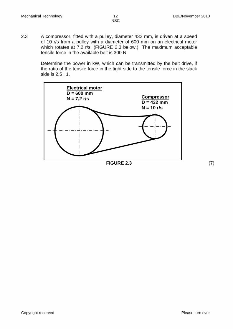
2.3 A compressor, fitted with a pulley, diameter 432 mm, is driven at a speed
of 10 r/s from a pulley with a diameter of 600 mm on an electrical motor which rotates at 7,2 r/s. (FIGURE 2.3 below.) The maximum acceptable tensile force in the available belt is 300 N. Determine the power in kW, which can be transmitted by the belt drive, if the ratio of the tensile force in the tight side to the tensile force in the slack side is 2,5 : 1.
FIGURE 2.3 (7)
Electrical motor D = 600 mm N = 7,2 r/s Compressor
D = 432 mm N = 10 r/s

Mechanical Technology 13 DBE/November 2010 NSC
Copyright reserved Please turn over
2.4 Study FIGURE 2.4 below. Lukas is the engineer who must design a gear
drive for a mincing machine. The shaft of the mincing machine must rotate at 90 r/min. The rest of the gear drive is as follows: On the electrical motor there is a driver gear A with 30 teeth, rotating at 480 r/min, that meshes in with a driven gear B with 80 teeth on a counter shaft. On the countershaft there is a second driver gear C with 20 teeth that meshes in with the final driven gear D.
FIGURE 2.4 Determine, by means of calculations, the following: 2.4.1 The number of teeth on the final driven gear D (4) 2.4.2 The gear ratio of the system (3)
A
T-30
B T-80
C
T-20
D T-?
Counter shaft
Electrical
motor Mincing machine

Mechanical Technology 14 DBE/November 2010 NSC
Copyright reserved Please turn over
2.5 Study FIGURE 2.5 below. A differential wheel and axle lifting machine is
used to lift an engine with a mass of 180 kg. The diameter of the wheel D is 300 mm and the diameters of the axles d2 and d1 are 150 mm and 120 mm respectively. The effort F, needed for this load, is 100 N.
FIGURE 2.5 Determine, by means of calculations, the following: 2.5.1 The mechanical advantage of the appliance (3) 2.5.2 The velocity ratio (2) 2.5.3 The mechanical efficiency of this machine at this load (2) 2.6 A single-plate friction clutch with an effective diameter of 250 mm is used
to transmit torque in the final drive. The clutch plate has friction material on both sides. The friction coefficient is 0,4. The total force applied on the pressure plate is 3 kN.
Determine, by means of calculations, the following: 2.6.1 The torque that can be transmitted by this clutch (3) 2.6.2 The power transmitted at 3 000 r/min (2) [50]
180 kg

Mechanical Technology 15 DBE/November 2010 NSC
Copyright reserved Please turn over
QUESTION 3: TOOLS AND EQUIPMENT 3.1 Explain how a voltmeter and an ammeter are connected to a circuit. (2)
3.2 What does the abbreviation MAGS/MIGS stand for in terms of welding
equipment?
(2) 3.3 State TWO uses of the multi-meter. (2) 3.4 Read the scenario below and answer the questions that follow. Mrs Gogo Xuma uses her car daily from her home to Durban and back.
She covers a distance of 42 km daily. Recently she discovered that her car is losing power. She asks Mr Manzi to assist her to find out why her car is losing power. Mr Manzi did a compression test on her car.
3.4.1 Give FOUR reasons for a compression test. (4) 3.4.2 Explain the procedure to carry out a dry compression test. (10) [20]
Mechanical Technology 16 DBE/November 2010 NSC
Copyright reserved Please turn over
QUESTION 4: MATERIALS
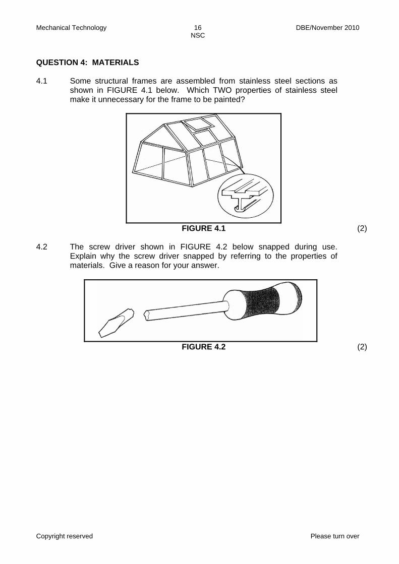
4.1 Some structural frames are assembled from stainless steel sections as shown in FIGURE 4.1 below. Which TWO properties of stainless steel make it unnecessary for the frame to be painted?
FIGURE 4.1 (2) 4.2 The screw driver shown in FIGURE 4.2 below snapped during use.
Explain why the screw driver snapped by referring to the properties of materials. Give a reason for your answer.
FIGURE 4.2 (2)

Mechanical Technology 17 DBE/November 2010 NSC
Copyright reserved Please turn over
4.3 Two test pieces, A and B, are tested for their toughness as shown in
FIGURE 4.3 below. After a single hammer blow test piece A broke from hammer position 1. Test piece B only broke after the hammer was moved to position 2. Refer to the hammer position and explain which one is the toughest.
FIGURE 4.3 (4) 4.4 Electrical cable is made by extruding a plastic coat onto copper wire as
shown in FIGURE 4.4 below. Name TWO plastics which are used for this purpose and also give ONE reason for the suitability of each.
FIGURE 4.4 (4) 4.5 What is understood by the term non-ferrous alloy? Give ONE example of a
non-ferrous alloy.
(2) 4.6 State TWO differences between silver soldering and brazing (hard
soldering) in terms of composition and uses. Draw a table to show the differences.
(4) 4.7 Name ONE of the carbon steels and state its carbon content as a
percentage.
(2) [20]
plastic
coated wire
copper wire
profile
Mechanical Technology 18 DBE/November 2010 NSC
Copyright reserved Please turn over
QUESTION 5: SAFETY, TERMINOLOGY AND JOINING METHODS 5.1 Mary uses a beam bending tester to test a work piece to determine its
degree of deflection. State FOUR safety precautions to be taken when using the beam bending tester.
(4) 5.2 Johannes cuts a solid diameter 25 mm mild steel shaft on a centre lathe.
The working environment of the centre lathe must be kept in a good condition. What FOUR safety precautions must Johannes consider before working on a centre lathe?
(4) 5.3 Give the reason why oil and grease should not be in contact with
oxy-acetylene regulators.
(2) 5.4 Name FOUR methods of indexing that can be used on the universal
dividing head of a milling machine.
(4) 5.5 Before Willy uses the milling machine, he needs to calculate the feed first.
Use the following information to calculate the feed in mm/min. (Hint: First calculate N.) Diameter of cutter = 100 mm Number of teeth = 24 Cutting speed = 40 m/min Feed per tooth = 0,09 mm per tooth
(6)
Mechanical Technology 19 DBE/November 2010 NSC
Copyright reserved Please turn over
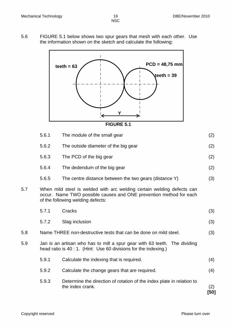
5.6 FIGURE 5.1 below shows two spur gears that mesh with each other. Use
the information shown on the sketch and calculate the following:
FIGURE 5.1 5.6.1 The module of the small gear (2) 5.6.2 The outside diameter of the big gear (2) 5.6.3 The PCD of the big gear (2) 5.6.4 The dedendum of the big gear (2) 5.6.5 The centre distance between the two gears (distance Y) (3) 5.7 When mild steel is welded with arc welding certain welding defects can
occur. Name TWO possible causes and ONE prevention method for each of the following welding defects:
5.7.1 Cracks (3) 5.7.2 Slag inclusion (3) 5.8 Name THREE non-destructive tests that can be done on mild steel. (3) 5.9 Jan is an artisan who has to mill a spur gear with 63 teeth. The dividing
head ratio is 40 : 1. (Hint: Use 60 divisions for the indexing.)
5.9.1 Calculate the indexing that is required. (4) 5.9.2 Calculate the change gears that are required. (4) 5.9.3 Determine the direction of rotation of the index plate in relation to
the index crank.
(2) [50]
teeth = 63 PCD = 48,75 mm
teeth = 39
Y
Mechanical Technology 20 DBE/November 2010 NSC
Copyright reserved Please turn over
QUESTION 6: MAINTENANCE AND TURBINES 6.1 You are instructed to machine a work piece using the milling machine. One
of the requirements is that you use a cutting fluid to ensure that it keeps the work piece cool. Give FOUR other reasons for using a cutting fluid.
(4) 6.2 Most car manufacturers recommend that their cars be serviced at a
10 000 km or 15 000 km intervals. Answer the questions that follow.
6.2.1 State THREE functions of engine oil. (3) 6.2.2 Explain the procedure to change the oil in the differential of a
rear wheel drive motor car.
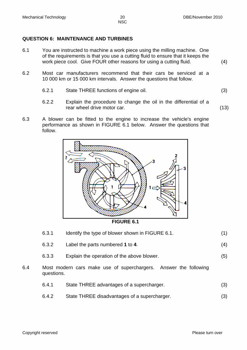
(13) 6.3 A blower can be fitted to the engine to increase the vehicle's engine
performance as shown in FIGURE 6.1 below. Answer the questions that follow.
FIGURE 6.1 6.3.1 Identify the type of blower shown in FIGURE 6.1. (1) 6.3.2 Label the parts numbered 1 to 4. (4) 6.3.3 Explain the operation of the above blower. (5) 6.4 Most modern cars make use of superchargers. Answer the following
questions.
6.4.1 State THREE advantages of a supercharger. (3) 6.4.2 State THREE disadvantages of a supercharger. (3)

Mechanical Technology 21 DBE/November 2010 NSC
Copyright reserved
6.5 State the function of the steam turbine. (2) 6.6 State TWO uses of the steam turbine. (2) [40] TOTAL: 200

Mechanical Technology 1 DBE/November 2010 NSC
Copyright reserved
FORMULA SHEET FOR MECHANICAL TECHNOLOGY – GRADE 12 1. BELT DRIVES
1.1 60πDNspeedBelt =
1.2 thickness)belt(t60
N)t D( πspeedBelt =×+
=
1.3 width) thickness (A density lengthAreamassBelt ×=××=
1.4
Diameter of driven pulleySpeed ratioDiameter of driver pulley
=
1.5 2211 DNDN =
1.6 2c4c
)d-D(2
)dDπ( length belt-Open2
+++
=
1.7 2c4c
)dD(2
)dDπ(lengthbelt-Crossed2
++
++
=
1.8 60
T N 2 Power π=
1.9 2
1
TT side slackto sidetight of Ratio =
1.10 sidetight the in forceT where60
N D π )T(T Power 121 =
−=
1.11 force tensile epermissibl
T Width 1=
2. FRICTION CLUTCHES
2.1
radiuseffective Rsurfacesfrictionofnumber n
forcetotal Wfrictionoftcoefficien µ
µWnR) T ( Torque
=====
2.2
60NT 2 π
=Power

Mechanical Technology 2 DBE/November 2010 NSC
Copyright reserved
3. STRESS AND STRAIN
3.1 )
AFσ(or
AreaForceess Str ==
3.2
)L(lengthoriginal)ΔL(lengthinchange)ε(in Stra =
3.3
)εσ(or
strainstress)E(ulusmodsYoung' =
3.4 4πdA
2
shaft =
3.5 4
)dπ(DA22
pipe−
=
4. HYDRAULICS
4.1 )A(Area)F(Force)P(Pressure =
4.2 )sorl(lengthstrokeareasectional-CrossVolume ×=
4.3 distance forcedone Work ×= 5. WHEEL AND AXLE
5.1 12 dd
2Ddistanceloaddistanceeffort)VR(ratioVelocity
−==
5.2 )F(Effort)W(Load)MA(advantageMechanical =
5.3 100% VRMA)η( efficiency Mechanical mech ×=
6. LEVERS
6.1 )F(Effort)W(Load)MA(advantageMechanical =
6.2 effortbymoveddistanceEffort)IM(movementnputI ×=
6.3 loadby moved distance Load) OM ( movement Output ×=
6.4 movementOutput
movementInput)VR(ratioVelocity =

Mechanical Technology 3 DBE/November 2010 NSC
Copyright reserved
7. GEAR DRIVES
7.1 60
NT 2 π=Power
7.2 gears driving on teeth of number the of Productgears driven on teeth of number the of Productratio Gear =
7.3 gears driving on teeth of number the of Productgears driven on teeth of number the of Product
NN
output
input =
7.4 radius forceTorque ×=
7.5 torqueinputratiogeardtransmitteTorque ×=
7.6 )T( teeth of Number
)PCD( diameter circle-Pitch)m( Module =
7.7 2211 TNTN =
7.8 π
)T( teeth of number )CP( pitch circular)PCD(diameter circle-Pitch ×=
7.9 module PCD)DO(diameter Outside 2+= 7.10 )m(module)a(Addendum = 7.11 m 1,25) b ( Dedendum orm1,157)b(Dedendum == 7.12 m 2,25) h ( depth Cutting orm 2,157 )h( depth Cutting == 7.13 m 0,25 ) c ( Clearanceorm 0,157 )c( Clearance == 7.14 πm)CP(pitchCircular ×=
Mechanical Technology 4 DBE/November 2010 NSC
Copyright reserved
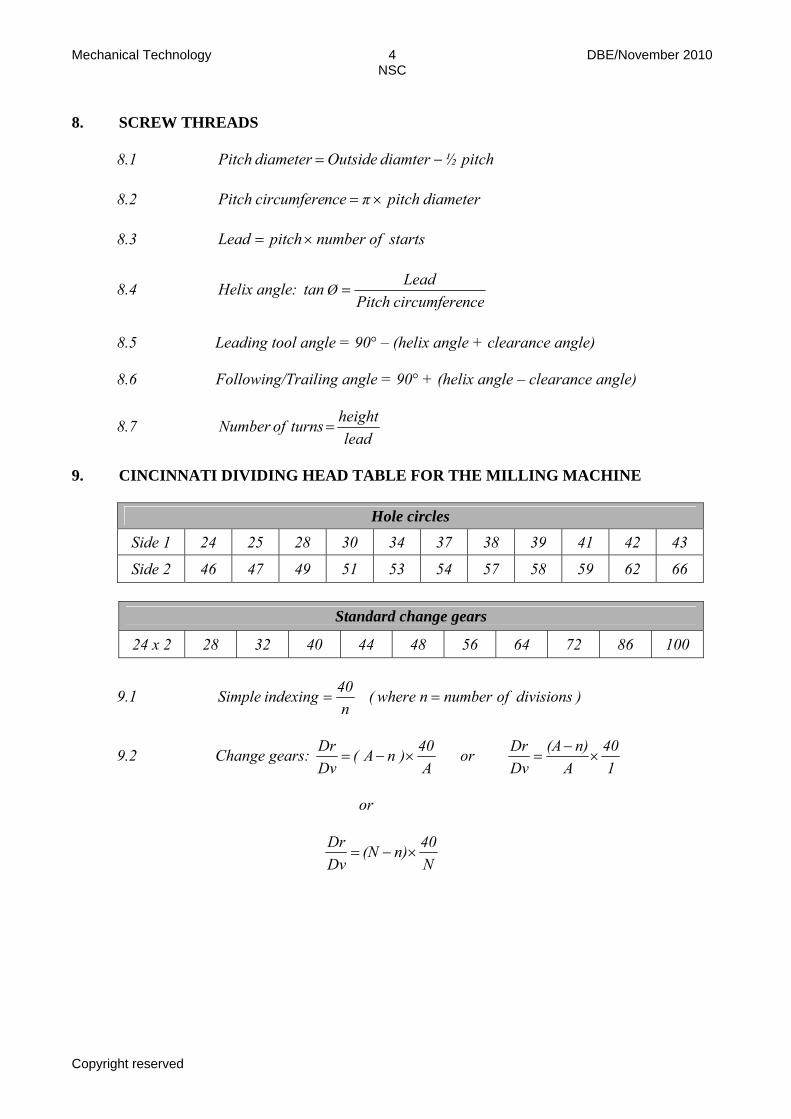
8. SCREW THREADS
8.1 pitch ½ diamter Outside diameter Pitch −= 8.2 diameterpitchπncecircumferePitch ×=
8.3 startsofnumberpitchLead ×=
8.4 ncecircumferePitch
Lead tan :angleHelix Ø =
8.5 Leading tool angle = 90° – (helix angle + clearance angle)
8.6 Following/Trailing angle = 90° + (helix angle – clearance angle)
8.7 lead
heightturnsofNumber =
9. CINCINNATI DIVIDING HEAD TABLE FOR THE MILLING MACHINE
Hole circles Side 1 24 25 28 30 34 37 38 39 41 42 43
Side 2 46 47 49 51 53 54 57 58 59 62 66
Standard change gears
24 x 2 28 32 40 44 48 56 64 72 86 100
9.1 )divisionsofnumbernwhere(n
40indexing Simple ==
9.2 Change gears: 1
40A
n)(ADvDror
A40)nA(
DvDr
×−
=×−=
or
N40n)(N
DvDr
×−=

Mechanical Technology 5 DBE/November 2010 NSC
Copyright reserved
10. CALCULATIONS OF FEED
10.1 Feed (f) = f1 ×T × N
Where: f = feed in millimetres per minute
f1 = feed per tooth in millimetres T = number of teeth on cutter N = number of revolutions of cutter per minute
10.2 Cutting speed (V) = NDπ ××
Where: D = diameter of the cutter in metres
****************************

Copyright reserved Please turn over
MARKS: 200
This memorandum consists of 18 pages.
MECHANICAL TECHNOLOGY
NOVEMBER 2010
MEMORANDUM
NATIONAL SENIOR CERTIFICATE
GRADE 12

Mechanical Technology 2 DBE/November 2010 NSC – Memorandum
Copyright reserved Please turn over
QUESTION 1: MULTIPLE CHOICE QUESTIONS
1.1 D √ (1)
1.2 C √ (1)
1.3 B √ (1)
1.4 D √ (1)
1.5 D √ (1)
1.6 B √ (1)
1.7 C √ (1)
1.8 A √ (1)
1.9 D √ (1)
1.10 B √ (1)
1.11 D √ C (1)
1.12 D √ (1)
1.13 D √ (1)
1.14 A √ (1)
1.15 D √ (1)
1.16 B √ (1)
1.17 B √ (1)
1.18 C √ (1)
1.19 A √ (1)
1.20 B √ (1) [20]

Mechanical Technology 3 DBE/November 2010 NSC – Memorandum
Copyright reserved Please turn over
QUESTION 2: FORCES, SYSTEMS AND CONTROL
2.1 HYDRAULICS
2.1.1 Calculate the fluid pressure in the system:
( )
MPa19,11MPa19,108
107,8510150
AFP
m107,854
0.1π
rA or 4πDA
3
3B
B
23
2
BB
==
××
=
=
×=
=
==
−
−
2π
√ √ √ √ (4)
2.1.2 Calculate the force on piston A:
( )
9,36kNN9363,9
100,49107,8510150
APF
m100,494
0,025π4πDA
33
3AA
23
2
2
A
==
××××
=
×=
×=
=
=
−−
−
√ √ √ √ (4)
2.1.3 Calculate force F:
N1560,650,48
0,089363,9F
0,089363,90,48F
=
×=
×=×
√√ √ √ (4)

Mechanical Technology 4 DBE/November 2010 NSC – Memorandum
Copyright reserved Please turn over
2.2 STRESS AND STRAIN
2.2.1 Calculate the maximum stress in part C:
( )
6,12MPaPa106,12
101,961012
AFσ
m101,964
0,05π4πDA
6
3
3C
C
23
2
2
C
=×=××
=
=
×=
=
=
−
−
√ √ √ √ √ (5)
2.2.2 Calculate the strain in part A:
( )
( )
0.00001414 or 100,01410108101,53
Eσε
MPa1,53Pa101,527
0,1π41012
Dπ4Fσ
AFσ
BUTEσε
εσE
3
9
6
AA
6
2
3
2A
A
AA
AA
A
A
−×=××
=
=
=×=
××=
×=
=
=
=
√ √ √ √ √ √ √ (7)
Mechanical Technology 5 DBE/November 2010 NSC – Memorandum
Copyright reserved Please turn over
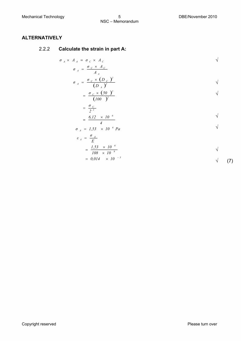
ALTERNATIVELY
2.2.2 Calculate the strain in part A:
( )( )
( )( )
3
9
6
AA
6A
6
2C
2
2C
2A
2CC
A
A
CCA
CCAA
100,01410108101,53
Eσε
Pa101,53σ4
106,122σ
10050σ
DDσσ
AAσσ
AσAσ
−×=××
=
=
×=
×=
=
×=
×=
×=
×=×
√ √ √ √ √ √ √ (7)

Mechanical Technology 6 DBE/November 2010 NSC – Memorandum
Copyright reserved Please turn over
2.3 BELT DRIVE
Calculate power transmitted:
( )( )
( )( )
kW2,44Watt2442,9
100,432π120300πDnTTP
ORkW2,44
Watt2442,97,20,6π120300
πDnTTP
N120T2,5300
2,5TT
2,5TT
21
21
2
12
2
1
==
××−=−=
==
×××−=−=
=
=
=
=
√ √ √ √ √√ √ OR √ √√ √
(7)
2.4 GEAR DRIVE
2.4.1 Calculate the number of teeth on the final gear D:
Teeth408090
2030480T
90480
2030T80
NN
gearsdriveronteethofnumberofProductgearsdrivenonteethofnumberofProduct
D
D
DN
DR
=×
××=
=××
=
√ √ √ √ (4)
Mechanical Technology 7 DBE/November 2010 NSC – Memorandum
Copyright reserved Please turn over
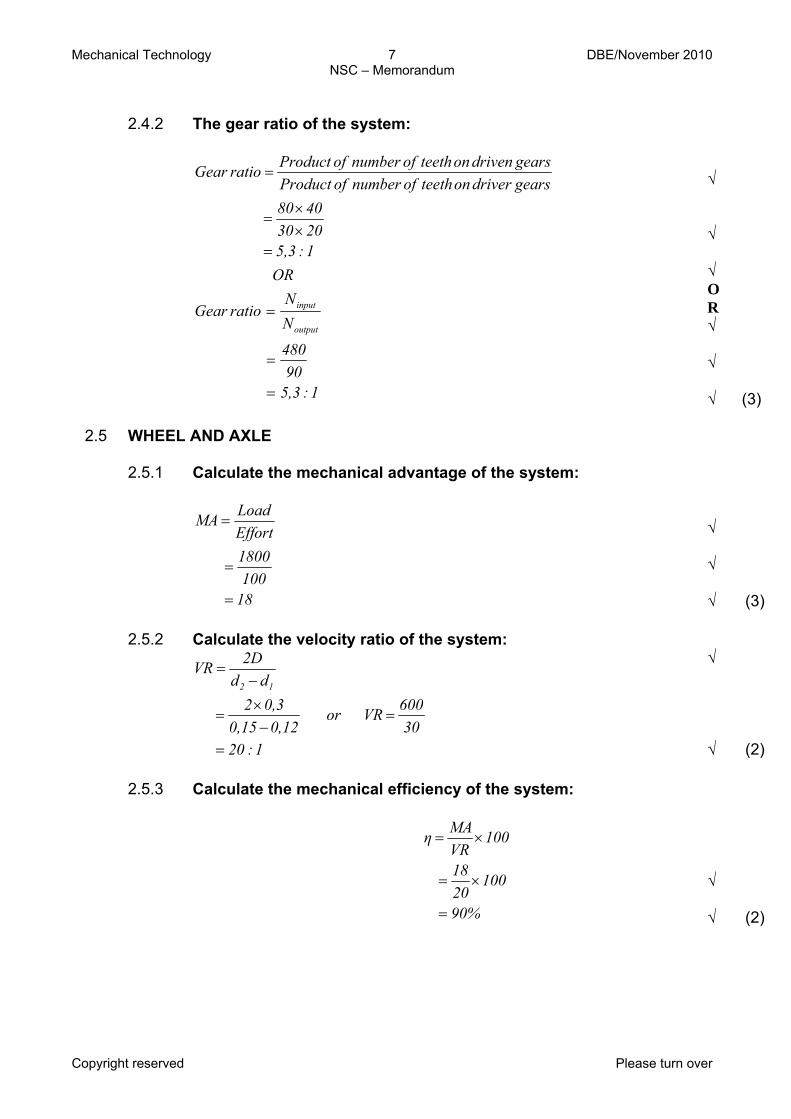
2.4.2 The gear ratio of the system:
1:5,390
480
NN
ratioGear
OR1:5,320304080
gearsdriveronteethofnumberofProductgearsdrivenonteethofnumberofProductratioGear
output
input
=
=
=
=××
=
=
√ √ √ OR √ √ √
(3)
2.5 WHEEL AND AXLE
2.5.1 Calculate the mechanical advantage of the system:
181001800EffortLoadMA
=
=
=
√ √ √ (3)
2.5.2 Calculate the velocity ratio of the system:
1:2030
600 VR or 0,120,15
0,32dd
2DVR12
=
=−×
=
−=
√ √ (2)
2.5.3 Calculate the mechanical efficiency of the system:
90%
1002018
100VRMAη
=
×=
×=
√ √
(2)

Mechanical Technology 8 DBE/November 2010 NSC – Memorandum
Copyright reserved Please turn over
2.6 CLUTCH
2.6.1 Calculate the torque transmitted by the clutch:
300Nm2
0,2521030,4
μWnRT
3
=
⎟⎠⎞
⎜⎝⎛××××=
=
√ √ √ (3)
2.6.2 Calculate the power transmitted:
94,25kWWatt 94247,78 or W1094,247
6030030002π
60 T N π 2P
3
=×=
××=
=
√ √
(2)
[50]

Mechanical Technology 9 DBE/November 2010 NSC – Memorandum
Copyright reserved Please turn over
QUESTION 3: TOOLS AND EQUIPMENT
3.1 VOLTMETER is connected in parallel with a circuit. AMMETER is connected in series with a circuit.
√ √ (2)
3.2 Metal Arc Gas Shielded/Metal Inert Gas Shielded √√ (2)
3.3 USES OF A MULTI-METER:
• Direct current measurement (DC) • Alternating current measurement (AC) • Diode and continuity measurement • Battery measurement • Resistance measurement • Temperature measurement • Transistor test • Direct current voltage measurement
(Any 2 x 1)
√ √ √ √ √ √ √ √
(2)
3.4 COMPRESSION TEST
3.4.1 Reasons for compression test:
• Valve clearances • Leaking exhaust valve • Leaking cylinder head gasket • Worn rings • Worn cylinders • Worn piston • Leaking inlet valve. • Loose cylinder head bolt • Cracked cylinder head • Cracked piston
(Any 4 x 1)
√ √ √ √ √ √
(4)
3.4.2 Dry compression test:
• Run engine until normal operating temperature is reached. • Air cleaner to be removed and jam the choke and throttle
valve in the open position, to allow maximum air to enter the combustion chamber.
• Disconnect the primary coil lead to prevent spark. • Clean area around spark plug and the screw the pressure
gauge into the spark plug hole. • Crank the engine until the gauge stops rising. • Test all the cylinders and compare the readings to the
manufacturer's specifications.
√√ √√ √ √√ √ √√
(10)[20]

Mechanical Technology 10 DBE/November 2010 NSC – Memorandum
Copyright reserved Please turn over
QUESTION 4: MATERIALS
4.1 PROPERTIES OF STAINLESS STEEL: • It has a shiny appearance due to chromium oxide film applied to the
surface • It has good resistance to corrosion due to a high chrome content.
√ √ (2)
4.2 SCREW DRIVER:
Reason: The material is too brittle. Support: A brittle material is the one that fractures with little or no deformation
√ √ (2)
4.3 HAMMER:
Material B is the toughest. Reason: Toughness is measured by the amount of energy needed to break the material. The higher the swing height of the hammer the higher the toughness of the material.
√√ √√
(4)
4.4 ELECTRICAL CABLE: Polyvinylchloride (PVC) and Polythene (Polyethylene) Reasons: They soften on heating and can be moulded into shape. On cooling they harden.
√√ √ √ (4)
4.5 NON-FERROUS ALLOYS:
A non-ferrous alloy is a metal that has a combination of two or more non-ferrous metals which are melted together to form one non-ferrous alloy. Example: Brass; Bronze; White metal; duralumin and solder (only one example)
√ √
(2)
4.6 Process Composition Uses
Silver soldering They are alloys of copper, zinc and silver, tin and lead √
They are used to produce strong ductile joints in copper, brass and in jewellery work √
Brazing They make use of zinc copper alloys
They are used to produce strong ductile joints in ferrous metals. √
(4)
4.7 CARBON STEEL:
Low carbon steel – 0,25% carbon or Medium carbon steel – 0,5 % carbon or High carbon steel – 1% carbon Select only ONE answer (2 x 1)
(2) [20]
Mechanical Technology 11 DBE/November 2010 NSC – Memorandum
Copyright reserved Please turn over
QUESTION 5: SAFETY, TERMINOLOGY AND JOINING METHODS
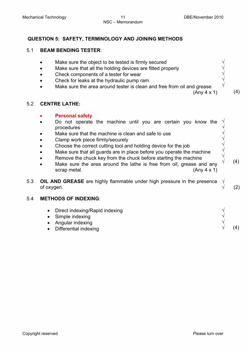
5.1 BEAM BENDING TESTER: • Make sure the object to be tested is firmly secured • Make sure that all the holding devices are fitted properly • Check components of a tester for wear • Check for leaks at the hydraulic pump ram. • Make sure the area around tester is clean and free from oil and grease
(Any 4 x 1)
√ √ √ √ √
(4)
5.2 CENTRE LATHE: • Personal safety • Do not operate the machine until you are certain you know the
procedures • Make sure that the machine is clean and safe to use • Clamp work piece firmly/securely • Choose the correct cutting tool and holding device for the job • Make sure that all guards are in place before you operate the machine • Remove the chuck key from the chuck before starting the machine • Make sure the area around the lathe is free from oil, grease and any
scrap metal. (Any 4 x 1)
√ √ √ √ √ √ √ √
(4)
5.3 OIL AND GREASE are highly flammable under high pressure in the presence
of oxygen. √ √ (2)
5.4 METHODS OF INDEXING:
• Direct indexing/Rapid indexing • Simple indexing • Angular indexing • Differential indexing
√ √ √ √ (4)

Mechanical Technology 12 DBE/November 2010 NSC – Memorandum
Copyright reserved Please turn over
5.5 FEED IN MILLIMETRE PER MINUTE:
mm/min275,01127,32240,09
NTffeedr/min127,32
0,1π40
πDvN
πDNvm0,1
1000100D
1
=××=
××==
×=
=
==
=
√ √ √ √ √ √ (6)
5.6 GEARS
5.6.1 Calculate the module of the small gear:
mm1,2539
48,75T
PCDm
=
=
=
√ √ (2)
5.6.2 Calculate the outside diameter of the big gear:
mm81,252)1,25(63
2)m(TdiameterOutside
=+=
+= or
81.25mm2.578.75
2.5631.252mTm2mPCDOD
=+=
+×=+×=+=
√ √ (2)
5.6.3 Calculate the PCD of the big gear:
mm78,75631,25
TmPCD
=×=
×=
√ √ (2)

Mechanical Technology 13 DBE/November 2010 NSC – Memorandum
Copyright reserved Please turn over
5.6.4 Calculate the dedendum of the big gear:
mm
mDedendumOR
mmmm
mDedendum
56,125,125,1
25,1
45,1446,1
25,1157,1157,1
=×=×=
==
×=×=
√ √ OR √ √
(2) (2)
5.6.5 The centre distance Y
mm63,752
48,7578,752
gearsmallPCDgearbigPCDYDistance
=
+=
+=
√ √ √ (3)
5.7 WELDING DEFECTS
5.7.1 Cracks:
Causes: • Atmospheric pollution • Wrong welding technique • Dirty or wet electrodes / corroded MIG wire • Wrong electrode • Stressed weld • Faulty weld joint preparation • Cooling rate too fast • Craters present
(Any 2 x 1) Corrective measures: • Use low hydrogen electrode. • Increase the temperature of the parts to be welded. • Fill craters with welding material. • Use the correct welding current settings.
(Any 1 x 1)
√ √ √ √ √ √ √ √ √ √ √ √
(2)
(1)

Mechanical Technology 14 DBE/November 2010 NSC – Memorandum
Copyright reserved Please turn over
5.7.2 Slag inclusion: Causes: • Rapid chilling • Repeating a weld without removing the previous slag • Weld temperature is too low • High viscosity of the molten metal • Included angle is too small
(Any 2 x 1) Corrective measures: • Remove slag from the previous weld run. • Increase the preparation angle.
(Any 1 x 1)
√ √ √ √ √ √ √
(2)
(1)
5.8 NON-DESTRUCTIVE TESTS: • Liquid dye penetrant • Ultrasonic • X-ray • Sound test • Hardness test • Visual inspection
(Any 3 x 1)
√ √ √ √ √ √
(3)
5.9 INDEXING
5.9.1 Calculate the required indexing:
circlehole24theonholes16and turns,fullNo2416
88
32326040n
40Indexing
=
×=
=
=
=
Other hole circles can also be allowed
√ √ √√ (4)
Mechanical Technology 15 DBE/November 2010 NSC – Memorandum
Copyright reserved Please turn over
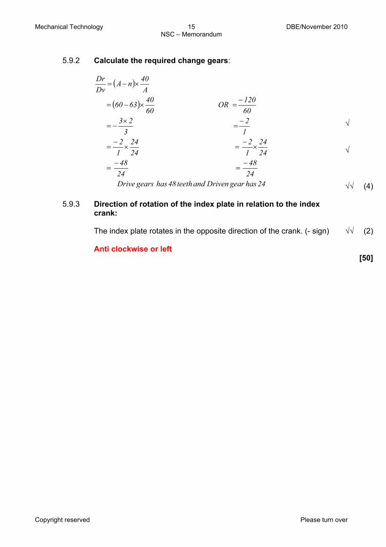
5.9.2 Calculate the required change gears:
( )
( )
24hasgearDrivenandteeth48hasgearsDrive2448
2448
2424
12
2424
12
12
323
60120OR
60406360
A40nA
DvDr
−=
−=
×−
=×−
=
−=
×−=
−=×−=
×−=
√ √ √√ (4)
5.9.3 Direction of rotation of the index plate in relation to the index
crank: The index plate rotates in the opposite direction of the crank. (- sign) Anti clockwise or left
√√ (2)
[50]

Mechanical Technology 16 DBE/November 2010 NSC – Memorandum
Copyright reserved Please turn over
QUESTION 6: MAINTENANCE AND TURBINES
6.1 CUTTING FLUIDS: • Carry away the heat generated by machining process. • Acts as a lubricant. • Prevents the chips/swarf from sticking and fusing to the cutter teeth. • Improve quality of the finish of machine surface. • To keep the cutting tool cool. • To obtain a higher cutting speed. • It gives the cutting tool a longer lifespan. • Does not rust the machine. • Helps to wash away the chips/swarf of the metal being removed from the
work piece, thus keeping the cutting edge of the cutting tool clean. (Any 4 x 1)
√ √ √ √ √ √ √ √ √ (4)
6.2 VEHICLE SERVICE
6.2.1 Functions of an oil:
• It lubricates • Provide cooling and control temperature • It acts as a seal • Reduce engine noise • Prolong engine life • It absorbs shocks and vibrations • Cleans the inside of the engine
(Any 3 x 1)
√ √ √ √ √ √ √
(3)
6.2.2 Draining and filling oil for differential unit: • Run the vehicle so that the rear axle oil is warm, so that it drains
easily. • Keep a drain tray that can hold all the oil at hand. • Clean area around the drain and filler plug. • Remove filler plug this will allow the oil to flow easily and fast. • Remove the drain plug using a correct spanner and allow oil to
drain into the tray. • Allow all the oil to drain out. • Wash the drain and filler plug. • Fit new washers to both the drain and filler plugs. • Replace the drain plug. • Fill oil using oil from a plastic dispenser. • Fill the oil until the oil just trickles out of the filler hole. • Do not overfill the rear axle because this can cause the side
shaft seals to fail • Replace filler plug and wipe off surplus oil
√ √√√ √√√√√√√ √√ (13)

Mechanical Technology 17 DBE/November 2010 NSC – Memorandum
Copyright reserved Please turn over
6.3 BLOWER
6.3.1 Centrifugal blower √ (1)
6.3.2 Components 1. Air inlet 2. Air outlet 3. Impeller 4. Fins
√ √ √ √ (4)
6.3.3 Operation:
• This blower can be driven mechanically by means of a belt drive
from the crank shaft or by means of exhaust gases moving through to the exhaust manifold
• The shaped fins on the impeller move the air around to the outer edge of the impeller into the housing.
• In doing so, the moving fins leave a low pressure behind it. • Air, under atmospheric pressure, rushes in to fill the low
pressure at the centre of the impeller. • The impeller rotates so fast that a continuous movement of air
is present which now builds up a pressure as it is thrown at the rim of the edge.
√ √ √ √ √ (5)
6.4 SUPER CHARGER
6.4.1 Advantages of a supercharger:
• More power is obtained compared to an engine with a similar
capacity without a supercharger • Supercharged engines are more economical per given kilowatt
output. • Less fuel is used compared to engine mass. • Power loss is eliminated above sea level.
(Any 3 x 1)
√ √ √ √
(3)

Mechanical Technology 18 DBE/November 2010 NSC – Memorandum
Copyright reserved
6.4.2 Disadvantages of a supercharger: • A small amount of power is lost in order to drive the
supercharger because it uses the engine power to drive it • Higher fuel consumption if the power generated is not fully
used, as in the case of passenger vehicles • Due to the compression of the air this results in an increase in
air temperature causing a decrease in the density of the inlet charge.
• The lifespan of the engine is decreased because of higher cylinder pressure, which increases the load on the engine components.
(Any 3 x 1)
√ √ √ √
(3)
6.5 FUNCTION OF STEAM TURBINE: • Steam turbines are operated by using steam that generates kinetic
energy • This generates rotational motion which is mechanical energy.
√ √ (2)
6.6 TURBINE USES:
• To power generators which generate large amounts of electricity. • To power ship propulsion.
√ √ (2)
[40]
TOTAL: 200