
GR-150XL - TADANO America Corporation€¦ · - Independently controlled outriggers with -...
12
Feet Meters Turning radius 4 wheel steer 14' 5-1/4" 4.4 2 wheel steer 24' 11-1/8" 7.6 Tail swing of counterweight 5' 3" 1.6 Specifications are subject to change without notice. GENERAL DIMENSIONS (315/80R22.5 Tires) HYDRAULIC ROUGH TERRAIN CRANE DIMENSIONS GR-150XL 15 Ton Capacity (13.6 Metric Tons)
Transcript of GR-150XL - TADANO America Corporation€¦ · - Independently controlled outriggers with -...

Feet MetersTurning radius 4 wheel steer 14' 5-1/4" 4.4 2 wheel steer 24' 11-1/8" 7.6Tail swing of counterweight 5' 3" 1.6
Specifications are subject to change without notice.
GENERAL DIMENSIONS (315/80R22.5 Tires)
HYDRAULIC ROUGH TERRAIN CRANE
DIMENSIONS
GR-150XL15 Ton Capacity (13.6 Metric Tons)

CRANE SPECIFICATIONS
BOOM WIRE ROPE - Warrington seal wire, extra improved plow steel,
6 section full power partially synchronized telescoping boom, preformed, independent wire rope core, right regular lay.17.4'~78' (5.3m~23.8m), of box construction with 4 sheaves, 7/16" (11.2mm) 6x37 class9-5/16" (0.236m) root diameter, at boom head. Breaking Strength - Main: 19,000 lbs (8,660 kg)The synchronization system consists of two double acting Breaking Strength - Aux : 20,000 lbs (9,100 kg)telescope cylinders , extension cables and retraction cables.Hydraulic cylinder fitted with holding valve. Boom telescope HOOK BLOCKS
sections are supported by wear pads both vertically and horizontally. 15 ton (13.6 metric ton)- 4 sheaves with swivel and safety latch.Extension speed 60.6' (18.5m) in 52 seconds. 2.0 ton (1.8 metric ton) - Weighted hook ball with swivel and safety latch.
BOOM ELEVATION - By a double acting hydraulic cylinder withholding valve. Elevation -3 o~82o, combination controls for hand HYDRAULIC SYSTEM
or foot operation.Automatic speed reduction and soft stop function. PUMPS - 2 variable piston pumps for crane functions.
Elevation speed -3 o to 82 o in 29 seconds Tandem gear pump for steering, slewing and accumulator.Powered by carrier engine. Pump disconnect for crane is
JIB - 2 stage extension type with 5 o, 25o,45o or 60o engaged/ disengaged by rotary switch from operator's cab.
offset(tilt type). Single sheave, 7-9/16" (0.192 m) root diameter, at jib head.Box type top section telescopes from box type base section CONTROL VALVES - Multiple valves actuated by pilot pressure
which stores under base boom section. with integral pressure relief valves.Jib length is 11.8' (3.6m) or 18' (5.5m).
RESERVOIR - 45 gallon (172 lit.) capacity. External sight levelAUXILIARY LIFTING SHEAVE (SINGLE TOP) gauge.
Single sheave, 7-9/16" (0.192 m) root diameter. Mounted to mainboom head for single line work. FILTRATION - BETA10=10 return filter, full flow with bypass
protection, located inside of hydraulic reservoir. Accessible forANTI-TWO BLOCK - Pendant type over-winding cut out device easy replacement.
with audio-visual (FAILURE lamp/BUZZER) warning system.OIL COOLER - Air cooled fan type.
SLEWING
Hydraulic axial piston motor through planetary slewing speedreducer. Continuous 360 o full circle slewing on ball bearing turn CAB AND CONTROLStable at 2.4min -1 {rpm}. Equipped with manually locked/released
slewing brake. A 360 o positive slewing lock for pick and carry and travel Both crane and drive operations can be performed from one cabmodes. mounted on rotating superstructure.
Right side, 1 man type, steel construction with sliding door accessHOIST and safety glass windows opening at side. Door window is
powered control. Windshield glass window and roof glass windowMAIN HOIST - Grooved drum driven by hydraulic axial piston are shatter-resistant. Wiper and washer (front windshield and roof
motor through winch speed reducer. Power load lowering and window). Tinted saftey glass and sun visor.raising. Equipped with automatic brake (neutral brake) and Tilt-telescoping steering wheel. Adjustable control lever forcounterbalance valve. Controlled independently of auxiliary hoist. slewing, boom elevating, boom telescoping, auxiliary winch and main winch. Equipped with cable follower and drum rotation indicator. Control lever can change
neutral positions and tilt for easy access to cab. 3 way adjustableMAIN DRUM operator's seat with high back, headrest and armrest. Engine
Grooved 10-7/16" (0.265m) root diameter x 9-7/16" (0.239m) wide. throttle knob. Foot operated controls: boom elevating,Wire rope: 450' of 7/16" diameter rope (137m of 11.2mm). boom telescoping, service brake and engine throttle. Drum capacity: 486.8' (148.4m) 7 layers. Hot water cab heater and air conditioning.Maximum line pull (available): 6,700lbs. (3,050kg).Maximum line speed: 410FPM (125m/min) at the 5th layer.
Dash-mounted engine start/stop, monitor lamps, cigarette lighter,AUXILIARY HOIST - Grooved drum driven by hydraulic axial drive selector switch, parking brake switch, steering mode
piston motor through winch speed reducer. Power load lowering select switch, power window switch, pump engaged/disengagedand raising. Equipped with automatic brake (neutral brake) and switch, slewing brake switch and outrigger controls.counterbalance valve. Controlled independently of main hoist.Equipped with cable follower and drum rotation indicator. Instruments - Torque converter oil temperature, engine water
temperature, air pressure, fuel, speedometer, tachometer,AUXILIARY DRUM hour meter and odometer / trip meter. Hydraulic oil pressure is
Grooved 10-7/16" (0.265m) root diameter x 9-7/16" (0.239m) wide. monitored and displayed on the AML-C display panel.Wire rope: 217' of 7/16" diameter rope (66m of 11.2mm).Drum capacity: 486.8' (148.4m) 7 layers.Maximum line pull (available): 6,700lbs. (3,050kg).Maximum line speed: 361FPM (110m/min) at the 3rd layer.
2

Tadano electronic LOAD MOMENT INDICATOR system TADANO AML-C monitors outrigger extended length and(AML-C) including: automatically programs the corresponding "RATED LIFTING Control lever lockout function CAPACITIES" table Boom position indicator Outrigger state indicator Operator's left hand console includes transmission gear selector Boom angle / boom length / jib offset angle / jib length / load and sight level bubble. Upper console includes roof washer
radius / rated lifting capacities / actual loads read out and wiper switch, emergency outrigger set up key switch, Ratio of actual load moment to rated load moment jib equipped/removed select switch and air conditioning control
indication switch. Automatic Speed Reduction and Slow Stop function
on boom elevation and slewing Working condition register switch Load radius / boom angle / tip height / slewing range NOTE: Each crane motion speed is based on unloaded
preset function conditions. External warning lamp Tare function Drum rotation indicator (audible and visible type) main and
auxiliary hoist
CARRIER SPECIFICATIONS
TYPE - Rear engine, left hand steering, driving axle 2-way SUSPENSION - Front: Semi-elliptic leaf springs with hydraulicselected type by manual switch, 4x2 front drive, 4x4 front and lockout device. Rear: Semi-elliptic leaf springs with hydraulicrear drive. lockout device.
FRAME - High tensile steel, all welded mono-box construction. BRAKE SYSTEMS - Service: Air over hydraulic disc brakes onall 4 wheels. Parking/Emergency: Spring applied-air released
TRANSMISSION - Electronically controlled full automatic brake acting on input shaft of front axle. Auxiliary: Electro-transmission. Torque converter driving full powershift with pneumatic operated exhaust brake.driving axle selector. 6 forward and 2 reverse speeds, constantmesh. TIRES - 315/80R22.5
2 speeds - high range - 2 wheel drive; 4 wheel drive3 speeds - low range - 4 wheel drive OUTRIGGERS - Four hydraulic, beam and jack outriggers.
Vertical jack cylinders equipped with integral holding valve. EachTRAVEL SPEED - 25 mph (41 km/h) outrigger beam and jack is controlled independently from cab.
Beams extend to 15' 5" (4.7 m) center-line and retract toAXLE - Front: Full floating type, steering and driving axle within 5' 4-1/2" (1.64 m) overall width with floats. Outrigger jack
with planetary reduction. floats are attached thus eliminating the need of manually AXLE - Rear: Full floating type, steering and driving axle attaching and detaching them. Controls and sight bubble located
with planetary reduction and non-spin rear differential. in superstructure cab. Four outrigger extension lengths areprovided with corresponding "RATED LIFTING CAPACITIES" for
STEERING- Hydraulic power steering controlled by steering crane duty in confined areas.wheel. Four steering modes available: 2 wheel front, 2 wheel rear, Min. Extension 5' 4-1/2" (1.64m) center to center4 wheel coordinated and 4 wheel crab. Mid. Extension 8' 2-3/8" (2.5m) center to center
Mid. Extension 11' 5-3/4" (3.5m) center to centerMid. Extension 14' 1-1/4" (4.3m) center to centerMax. Extension 15' 5" (4.7m) center to centerFloat size(Diameter) 1' 1- 3/4" (0.35m)
ENGINEModel Mitsubishi 4M50-TLA3B Radiator Fin and tube core, thermostat controlledType Direct injection diesel Fan, in.(mm) Suction type, 10-blade, 18 (457) dia.No. of cylinders 4 Starting 24 voltCombustion 4 cycle, turbo charged and after cooled Charging 24 volt system, negative groundBore x Stroke, in.(mm) 4.488 X 4.724 (114X120) Battery 2-80 amp. HourDisplacement, cu. in (liters) 299 (4.900) Compressor, air, CFM(l /min) 21.6 CFM (612) at 2,700rpmAir inlet heater 24 volt preheat Output, Max. HP (kW) Gross 172 (129) at 2,700rpmAir cleaner Dry type, replaceable element Torque, Max. ft-lb (Nm) 390 (529) at 1,600rpmOil filter Full flow with replaceable element Capacity, gal.(liters)Fuel filter Full flow with replaceable element Cooling water 2.9 (11)Fuel tank, gal.(liters) 50 (189), right side of carrier Lubrication 2.1 ~ 2.9 (8 ~11)Cooling Liquid pressurized, recirculating by-pass Fuel 50 (189)
Lower console includes working light switch and boom emergencytelescoping switch (2nd-3rd and 4th-top).
3

- Six section full power partially synchronized boom - Mitsubishi 4M50-TL turbo charged after17.4' ~ 78' (5.3 m~23.8 m) cooled engine (172HP) with exhaust brake
- 11.8' or 18' (3.6 m or 5.5 m) box jib (tilt type) - Electronic controlled automatic transmission drivenwith 5 o, 25o, 45o and 60o pinned offsets and self storing pins. by torque converter
- Auxiliary lifting sheave (single top). - 4 X 4 X 4 drive/steer- Main hoist with grooved drum and 450' of 7/16" cable. - Semi-elliptic leaf springs suspension with hydraulic lockout- Auxiliary hoist with grooved drum and 217' of 16" cable. device (front and rear)- Drum rotation indicator (visible type) - 315/80R22.5 tires- Anti-Two block device (overwind cutout) - Disc brakes- Tadano electronic load moment indicator system (AML-C) - Fenders- Outrigger extension length detector - Air dryer- Electronic crane monitoring system - Water separator with filter- Self centering finger control levers with pilot control - Engine over-run alarm- Control pedals for boom elevating and boom telescoping - Back-up alarm- 3 way adjustable cloth seat with armrests, high back - Low oil pressure/high water temp. warning device (visual)
and seat belt - Rear steer centering light- Tilt-telescoping steering wheel - Air cleaner dust indicator- Tinted safety glass and sun visor - Full instrumentation package- Front windshield wiper and washer - Complete highway light package- Roof window wiper and washer - Tool storage compartment- Power window (cab door) - Tire inflation kit- Rear view mirrors (right and left side) - 24 volt electric system- Cigarette lighter - 2.0 ton (1.8 metric ton) hook ball with swivel- Cab floor mat - 15 ton (13.6 metric ton) hook block with swivel- Pump disconnect in operator's cab - Towing hooks-Front and rear- Hydraulic oil cooler - Fuel consumption monitor (#FD2021~)- Hot water cab heater and air conditioner - Eco mode system (#FD2247~)- Work lights - Telematics (machine data logging and monitoring system)- Independently controlled outriggers with - HELLO-NET via internet (#FD3345~)- Five outrigger extension positions- Self-storing outrigger pads
HOISTING PERFORMANCELINE SPEEDS AND PULLS DRUM WIRE ROPE CAPACITIES
Drum grooved lagging
Line pulls 7/16" (11.2mm) wire rope Available2 Total wire rope
F.P.M. m/min Lbs. kgf Feet Meters1st 308 94 6700 3050 1 57.0 17.42nd 330 101 6200 2810 2 118.3 36.03rd 361 108 5700 2610 3 183.6 56.04th 375 114 5400 2430 4 253.2 77.25th 410 121 5000 2280 5 326.9 99.66th 420 128 4700 2140 6 404.8 123.47th 443 135 4500 2020 7 486.8 148.4
* Maximum permissible line pull may be affected by wire rope strengthMaximum lifting capacity per line (Main & Aux): 4,000 lbs. (1,800kg
DRUM DIMENSIONS1 Line speeds based only on hook block, not loaded. Inch mm2 Developed by machinery with each layer of wire rope, but not based Root diameter 10-7/16" 265
on rope strength or other limitation in machinery or equipment. Length 9-7/16" 239Flange diameter 1' 5-11/16" 450
Layer
Main or auxiliary hoist - 10'-7/8" (0.28m) drum
STANDARD EQUIPMENT
Line speeds1
Wire rope layer
4
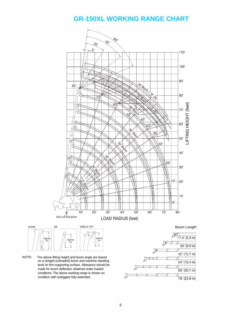
GR-150XL WORKING RANGE CHART
Boom Length
NOTE: The above lifting height and boom angle are based on a straight (unloaded) boom and machine standing level on firm supporting surface. Allowance should be made for boom deflection obtained under loaded conditions. The above working range is shown on condition with outriggers fully extended.
5
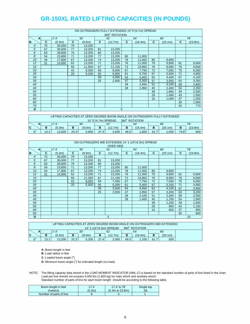
GR-150XL RATED LIFTING CAPACITIES (IN POUNDS)
ON OUTRIGGERS FULLY EXTENDED 15' 5"(4.7m) SPREAD
360o ROTATIONA 17.4' 30' 42' 54' 66' 78'
B C (5.3m) C (9.0m) C (12.7m) C (16.4m) C (20.1m) C (23.8m)4' 70 30,000 79 13,2005' 67 30,000 77 13,200 81 13,2006' 63 28,800 75 13,200 80 13,2008' 54 23,800 71 13,200 77 13,200 80 11,00010' 44 17,800 67 13,200 74 13,200 78 11,000 80 9,90012' 31 14,800 62 13,200 71 13,200 76 11,000 79 9,900 81 6,60015' 55 11,500 67 11,100 72 10,850 76 8,950 79 6,60020' 42 8,300 59 8,000 67 7,750 72 7,050 75 6,05025' 20 6,200 50 5,850 61 5,700 67 5,500 71 4,95030' 39 4,050 54 4,400 62 4,400 67 4,10035' 25 2,950 47 3,350 57 3,550 63 3,35040' 39 2,650 51 3,150 58 2,80045' 28 1,950 45 2,400 54 2,35050' 38 1,850 49 2,00055' 29 1,400 43 1,55060' 16 1,050 37 1,25065' 30 1,00070' 20 770D 0
LIFTING CAPACITIES AT ZERO DEGREE BOOM ANGLE ON OUTRIGGERS FULLY EXTENDED
15' 5"(4.7m) SPREAD 360o ROTATIONA 17.4' 30' 42' 54' 66' 78'
C B (5.3m) B (9.0m) B (12.7m) B (16.4m) B (20.1m) B (23.8m)
0o 13.1' 13,500 25.3' 5,900 37.4' 2,600 49.5' 1,600 61.7' 1,000 73.8' 600
ON OUTRIGGERS MID EXTENDED 14' 1-1/4"(4.3m) SPREADOVER SIDE
A 17.4' 30' 42' 54' 66' 78'B C (5.3m) C (9.0m) C (12.7m) C (16.4m) C (20.1m) C (23.8m)
4' 70 30,000 79 13,2005' 67 30,000 77 13,200 81 13,2006' 63 28,800 75 13,200 80 13,2008' 54 23,800 71 13,200 77 13,200 80 11,00010' 44 17,800 67 13,200 74 13,200 78 11,000 80 9,90012' 31 14,800 62 13,200 71 13,200 76 11,000 79 9,900 81 6,60015' 55 11,300 67 11,100 72 10,850 76 8,950 79 6,60020' 42 8,050 59 7,450 67 7,750 72 7,050 75 6,05025' 20 5,500 50 5,300 61 5,400 67 5,100 71 4,95030' 39 3,500 54 4,050 62 4,100 67 3,90035' 25 2,500 47 2,850 57 3,200 63 3,20040' 39 2,100 51 2,300 58 2,55045' 28 1,450 45 1,750 54 1,95050' 38 1,250 49 1,50055' 29 900 43 1,15060' 16 600 37 90065' 30 600D 0 23
LIFTING CAPACITIES AT ZERO DEGREE BOOM ANGLE ON OUTRIGGERS MID EXTENDED
14' 1-1/4"(4.3m) SPREAD 360o ROTATIONA 17.4' 30' 42' 54' 66'
C B (5.3m) B (9.0m) B (12.7m) B (16.4m) B (20.1m)
0o 13.1' 13,200 25.3' 5,200 37.4' 2,000 49.5' 1,100 61.7' 500
A :Boom length in feetB :Load radius in feet
C :Loaded boom angle (o)
D :Minimum boom angle (o) for indicated length (no load)
NOTE: The lifting capacity data stored in the LOAD MOMENT INDICATOR (AML-C) is based on the standard number of parts of line listed in the chart.Load per line should not surpass 4,000 lbs (1,800 kg) for main winch and auxiliary winch.Standard number of parts of line for each boom length should be according to the following table.
Boom length in feet 17.4' 17.4' to 78' Single top(meters) (5.3m) (5.3m to 23.8m) Jib
Number of parts of line 8 4 1
6

GR-150XL RATED LIFTING CAPACITIES (IN POUNDS)
ON OUTRIGGERS MID EXTENDED 11' 5-3/4"(3.5m) SPREADOVER SIDE
A 17.4' 30' 42' 54' 66' 78'B C (5.3m) C (9.0m) C (12.7m) C (16.4m) C (20.1m) C (23.8m)
4' 70 30,000 79 13,2005' 67 30,000 77 13,200 81 13,2006' 63 28,800 75 13,200 80 13,2008' 54 23,800 71 13,200 77 13,200 80 11,00010' 44 17,800 67 13,200 74 13,200 78 11,000 80 9,90012' 31 14,800 62 13,200 71 13,200 76 11,000 79 9,900 81 6,60015' 55 10,150 67 10,000 72 9,450 76 8,950 79 6,60020' 42 5,800 59 5,550 67 6,300 71 6,550 75 5,95025' 20 3,600 50 3,400 60 4,050 67 4,400 71 4,50030' 39 2,100 54 2,650 61 3,000 67 3,10035' 25 1,250 47 1,800 56 2,050 62 2,25040' 38 1,150 51 1,350 58 1,55045' 28 700 45 950 53 1,05050' 37 650 48 70055' 43 450D 0 26 39
LIFTING CAPACITIES AT ZERO DEGREE BOOM ANGLE ON OUTRIGGERS MID EXTENDED 11' 5-3/4"(3.5m) SPREAD 360o ROTATION
A 17.4' 30' 42' 54'C B (5.3m) B (9.0m) B (12.7m) B (16.4m)
0o 13.1' 13,200 25.3' 3,300 37.4' 1,000 49.5' 400
ON OUTRIGGERS MID EXTENDED 8' 2-3/8"(2.5m) SPREADOVER SIDE
A 17.4' 30' 42' 54' 66' 78'B C (5.3m) C (9.0m) C (12.7m) C (16.4m) C (20.1m) C (23.8m)
4' 70 30,000 79 13,2005' 67 30,000 77 13,200 81 13,2006' 63 28,800 75 13,200 80 13,2008' 54 18,700 71 13,200 77 13,200 80 11,00010' 44 12,200 67 11,800 74 11,800 78 11,000 80 9,90012' 31 8,800 62 8,600 71 8,550 76 9,250 79 9,900 81 6,60015' 55 5,450 66 5,350 72 6,000 76 6,300 79 6,60020' 42 2,850 58 2,750 66 3,300 71 3,600 75 3,85025' 20 1,500 50 1,350 60 1,900 66 2,200 70 2,35030' 39 500 54 1,000 61 1,350 66 1,45035' 47 500 56 750 62 85040' 58 450D 0 30 41 49 55
LIFTING CAPACITIES AT ZERO DEGREE BOOM ANGLE ON OUTRIGGERS MID EXTENDED 8' 2-3/8"(2.5m) SPREAD 360o ROTATION
A 17.4' 30'C B (5.3m) B (9.0m)
0o 13.1' 7,400 25.3' 1,300
ON OUTRIGGERS MIN EXTENDED 5' 4-1/2"(1.64m) SPREADOVER SIDE
A 17.4' 30' 42' 54' 66' 78'B C (5.3m) C (9.0m) C (12.7m) C (16.4m) C (20.1m) C (23.8m)
4' 70 17,500 79 13,2005' 67 15,300 77 12,800 81 12,5006' 63 13,250 75 12,300 80 12,5008' 54 8,650 71 8,800 77 8,300 80 7,50010' 44 5,800 67 6,100 74 5,600 78 5,600 80 5,60012' 30 4,250 62 4,100 71 4,050 75 4,200 78 4,300 80 4,35015' 55 2,450 66 2,300 72 2,700 76 3,000 78 3,10020' 42 900 59 750 66 1,250 71 1,550 74 1,80025' 70 950D 0 26 52 58 63 67
LIFTING CAPACITIES AT ZERO DEGREE BOOM ANGLE ON OUTRIGGERS MIN EXTENDED 8' 2-3/8"(2.5m) SPREAD 360o ROTATION
A 17.4'C B (5.3m)
0o 13.1' 3,500
A :Boom length in feet B :Load radius in feet C :Loaded boom angle (o) D :Minimum boom angle (o) for indicated length (no load)
NOTE: The lifting capacity data stored in the LOAD MOMENT INDICATOR (AML-C) is based on the standard number of parts of line listed in the chart.Load per line should not surpass 4,000 lbs (1,800 kg) for main winch and auxiliary winch.Standard number of parts of line for each boom length should be according to the following table.
Boom length in feet 17.4' 17.4' to 78' Single top(meters) (5.3m) (5.3m to 23.8m) Jib
Number of parts of line 8 4 1
7
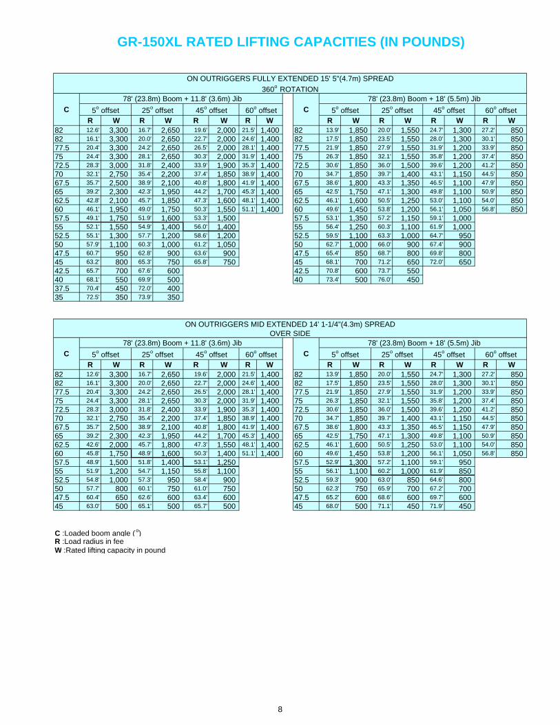
GR-150XL RATED LIFTING CAPACITIES (IN POUNDS)
ON OUTRIGGERS FULLY EXTENDED 15' 5"(4.7m) SPREAD
360o ROTATION78' (23.8m) Boom + 11.8' (3.6m) Jib 78' (23.8m) Boom + 18' (5.5m) Jib
C 5o offset 25o offset 45o offset 60o offset C 5o offset 25o offset 45o offset 60o offsetR W R W R W R W R W R W R W R W
82 12.6' 3,300 16.7' 2,650 19.6' 2,000 21.5' 1,400 82 13.9' 1,850 20.0' 1,550 24.7' 1,300 27.2' 85082 16.1' 3,300 20.0' 2,650 22.7' 2,000 24.6' 1,400 82 17.5' 1,850 23.5' 1,550 28.0' 1,300 30.1' 85077.5 20.4' 3,300 24.2' 2,650 26.5' 2,000 28.1' 1,400 77.5 21.9' 1,850 27.9' 1,550 31.9' 1,200 33.9' 85075 24.4' 3,300 28.1' 2,650 30.3' 2,000 31.9' 1,400 75 26.3' 1,850 32.1' 1,550 35.8' 1,200 37.4' 85072.5 28.3' 3,000 31.8' 2,400 33.9' 1,900 35.3' 1,400 72.5 30.6' 1,850 36.0' 1,500 39.6' 1,200 41.2' 85070 32.1' 2,750 35.4' 2,200 37.4' 1,850 38.9' 1,400 70 34.7' 1,850 39.7' 1,400 43.1' 1,150 44.5' 85067.5 35.7' 2,500 38.9' 2,100 40.8' 1,800 41.9' 1,400 67.5 38.6' 1,800 43.3' 1,350 46.5' 1,100 47.9' 85065 39.2' 2,300 42.3' 1,950 44.2' 1,700 45.3' 1,400 65 42.5' 1,750 47.1' 1,300 49.8' 1,100 50.9' 85062.5 42.8' 2,100 45.7' 1,850 47.3' 1,600 48.1' 1,400 62.5 46.1' 1,600 50.5' 1,250 53.0' 1,100 54.0' 85060 46.1' 1,950 49.0' 1,750 50.3' 1,550 51.1' 1,400 60 49.6' 1,450 53.8' 1,200 56.1' 1,050 56.8' 85057.5 49.1' 1,750 51.9' 1,600 53.3' 1,500 57.5 53.1' 1,350 57.2' 1,150 59.1' 1,00055 52.1' 1,550 54.9' 1,400 56.0' 1,400 55 56.4' 1,250 60.3' 1,100 61.9' 1,00052.5 55.1' 1,300 57.7' 1,200 58.6' 1,200 52.5 59.5' 1,100 63.3' 1,000 64.7' 95050 57.9' 1,100 60.3' 1,000 61.2' 1,050 50 62.7' 1,000 66.0' 900 67.4' 90047.5 60.7' 950 62.8' 900 63.6' 900 47.5 65.4' 850 68.7' 800 69.8' 80045 63.2' 800 65.3' 750 65.8' 750 45 68.1' 700 71.2' 650 72.0' 65042.5 65.7' 700 67.6' 600 42.5 70.8' 600 73.7' 55040 68.1' 550 69.9' 500 40 73.4' 500 76.0' 45037.5 70.4' 450 72.0' 40035 72.5' 350 73.9' 350
ON OUTRIGGERS MID EXTENDED 14' 1-1/4"(4.3m) SPREADOVER SIDE
78' (23.8m) Boom + 11.8' (3.6m) Jib 78' (23.8m) Boom + 18' (5.5m) Jib
C 5o offset 25o offset 45o offset 60o offset C 5o offset 25o offset 45o offset 60o offsetR W R W R W R W R W R W R W R W
82 12.6' 3,300 16.7' 2,650 19.6' 2,000 21.5' 1,400 82 13.9' 1,850 20.0' 1,550 24.7' 1,300 27.2' 85082 16.1' 3,300 20.0' 2,650 22.7' 2,000 24.6' 1,400 82 17.5' 1,850 23.5' 1,550 28.0' 1,300 30.1' 85077.5 20.4' 3,300 24.2' 2,650 26.5' 2,000 28.1' 1,400 77.5 21.9' 1,850 27.9' 1,550 31.9' 1,200 33.9' 85075 24.4' 3,300 28.1' 2,650 30.3' 2,000 31.9' 1,400 75 26.3' 1,850 32.1' 1,550 35.8' 1,200 37.4' 85072.5 28.3' 3,000 31.8' 2,400 33.9' 1,900 35.3' 1,400 72.5 30.6' 1,850 36.0' 1,500 39.6' 1,200 41.2' 85070 32.1' 2,750 35.4' 2,200 37.4' 1,850 38.9' 1,400 70 34.7' 1,850 39.7' 1,400 43.1' 1,150 44.5' 85067.5 35.7' 2,500 38.9' 2,100 40.8' 1,800 41.9' 1,400 67.5 38.6' 1,800 43.3' 1,350 46.5' 1,150 47.9' 85065 39.2' 2,300 42.3' 1,950 44.2' 1,700 45.3' 1,400 65 42.5' 1,750 47.1' 1,300 49.8' 1,100 50.9' 85062.5 42.6' 2,000 45.7' 1,800 47.3' 1,550 48.1' 1,400 62.5 46.1' 1,600 50.5' 1,250 53.0' 1,100 54.0' 85060 45.8' 1,750 48.9' 1,600 50.3' 1,400 51.1' 1,400 60 49.6' 1,450 53.8' 1,200 56.1' 1,050 56.8' 85057.5 48.9' 1,500 51.8' 1,400 53.1' 1,250 57.5 52.9' 1,300 57.2' 1,100 59.1' 95055 51.9' 1,200 54.7' 1,150 55.8' 1,100 55 56.1' 1,100 60.2' 1,000 61.9' 85052.5 54.8' 1,000 57.3' 950 58.4' 900 52.5 59.3' 900 63.0' 850 64.6' 80050 57.7' 800 60.1' 750 61.0' 750 50 62.3' 750 65.9' 700 67.2' 70047.5 60.4' 650 62.6' 600 63.4' 600 47.5 65.2' 600 68.6' 600 69.7' 60045 63.0' 500 65.1' 500 65.7' 500 45 68.0' 500 71.1' 450 71.9' 450
C :Loaded boom angle ( o)R :Load radius in feeW :Rated lifting capacity in pounds
8

GR-150XL RATED LIFTING CAPACITIES (IN POUNDS)
ON OUTRIGGERS MID EXTENDED 11' 5-3/4"(3.5m) SPREADOVER SIDE
78' (23.8m) Boom + 11.8' (3.6m) Jib 78' (23.8m) Boom + 18' (5.5m) Jib
C 5o offset 25o offset 45o offset 60o offset C 5o offset 25o offset 45o offset 60o offsetR W R W R W R W R W R W R W R W
82 12.6' 3,300 16.7' 2,650 19.6' 2,000 21.5' 1,400 82 13.9' 1,850 20.0' 1,550 24.7' 1,300 27.2' 85082 16.1' 3,300 20.0' 2,650 22.7' 2,000 24.6' 1,400 82 17.5' 1,850 23.5' 1,550 28.0' 1,300 30.1' 85077.5 20.4' 3,300 24.2' 2,650 26.5' 2,000 28.1' 1,400 77.5 21.9' 1,850 27.9' 1,550 31.9' 1,200 33.9' 85075 24.4' 3,300 28.1' 2,650 30.3' 2,000 31.9' 1,400 75 26.3' 1,850 32.1' 1,550 35.8' 1,200 37.4' 85072.5 28.3' 2,850 31.8' 2,400 33.9' 1,900 35.3' 1,400 72.5 30.6' 1,850 36.0' 1,500 39.6' 1,200 41.2' 85070 31.8' 2,400 35.4' 2,200 37.4' 1,850 38.9' 1,400 70 34.7' 1,850 39.7' 1,400 43.1' 1,150 44.5' 85067.5 35.3' 2,000 38.7' 1,850 40.8' 1,600 41.9' 1,400 67.5 38.6' 1,650 43.3' 1,300 46.5' 1,100 47.9' 85065 38.7' 1,550 41.9' 1,500 43.8' 1,400 45.3' 1,400 65 42.2' 1,450 46.9' 1,150 49.8' 1,000 50.9' 85062.5 42.0' 1,200 45.7' 1,200 46.9' 1,150 47.9' 1,150 62.5 45.7' 1,200 50.2' 1,000 52.9' 850 53.8' 75060 45.2' 900 48.9' 950 49.8' 900 50.7' 900 60 48.9' 900 53.4' 800 55.8' 700 56.6' 65057.5 48.3' 700 51.8' 750 52.6' 700 57.5 52.2' 700 56.7' 600 58.7' 60055 51.4' 550 54.2' 550 55.4' 500 55 55.6' 500 59.7' 450 61.6' 450
ON OUTRIGGERS MID EXTENDED 8' 2-3/8"(2.5m) SPREADOVER SIDE
78' (23.8m) Boom + 11.8' (3.6m) Jib 78' (23.8m) Boom + 18' (5.5m) Jib
C 5o offset 25o offset 45o offset 60o offset C 5o offset 25o offset 45o offset 60o offsetR W R W R W R W R W R W R W R W
82 12.6' 3,300 16.7' 2,650 19.6' 2,000 21.5' 1,400 82 13.9' 1,850 20.0' 1,550 24.7' 1,300 27.2' 85082 16.1' 3,200 20.0' 2,650 22.7' 2,000 24.6' 1,400 82 17.5' 1,850 23.5' 1,550 28.0' 1,300 30.1' 85077.5 20.1' 2,850 23.9' 2,300 26.3' 1,900 28.1' 1,400 77.5 21.9' 1,850 27.7' 1,500 31.9' 1,200 33.9' 85075 23.9' 2,400 27.7' 2,000 30.0' 1,750 31.9' 1,400 75 26.3' 1,850 31.9' 1,400 35.7' 1,100 37.4' 85072.5 27.5' 1,800 31.1' 1,550 33.5' 1,400 35.1' 1,150 72.5 30.2' 1,500 35.5' 1,100 39.1' 900 41.1' 75070 31.0' 1,250 34.5' 1,100 36.7' 1,000 38.3' 850 70 33.9' 1,100 39.3' 850 42.8' 750 44.4' 65067.5 34.5' 900 37.9' 800 39.9' 700 41.4' 570 67.5 37.6' 80065 37.8' 550 41.1' 500 43.0' 450 44.3' 300 65 41.0' 450
C :Loaded boom angle ( o)R :Load radius in feeW :Rated lifting capacity in pounds
9
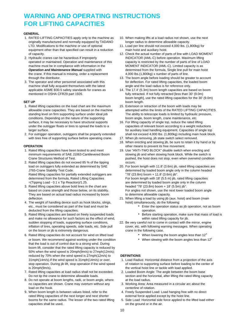
WARNING AND OPERATING INSTRUCTIONSFOR LIFTING CAPACITIESGENERAL1. RATED LIFTING CAPACITIES apply only to the machine as 10. When making lifts at a load radius not shown, use the next
originally manufactured and normally equipped by TADANO longer radius to determine allowable capacity.LTD. Modifications to the machine or use of optional 11. Load per line should not exceed 4,000 lbs. (1,800kg) forequipment other than that specified can result in a reduction main hoist and auxiliary hoist.of capacity. 12. Check the actual number of parts of line with LOAD MOMENT
2. Hydraulic cranes can be hazardous if improperly INDICATOR (AML-C) before operation. Maximum liftingoperated or maintained. Operation and maintenance of this capacity is restricted by the number of parts of line of LOADmachine must be in compliance with information in the MOMENT INDICATOR (AML-C). Limited capacity is asOperation and Maintenance Manual supplied with determined from the formula, Single line pull for main hoistthe crane. If this manual is missing, order a replacement 4,000 lbs.(1,800kg) x number of parts of line.through the distributor. 13. The boom angle before loading should be greater to account
3. The operator and other personnel associated with this for deflection. For rated lifting capacities, the loaded boommachine shall fully acquaint themselves with the latest angle and the load radius is for reference only.applicable ASME B30.5 safety standards for cranes as 14. The 17.4' (5.3m) boom length capacities are based on boommentioned in OSHA CFR29 part 1926. fully retracted. If not fully retracted [less than 30' (9.0m)
boom length], use the rated lifting capacities for the 30' (9.0m)SET UP boom length.1. Rated lifting capacities on the load chart are the maximum 15. Extension or retraction of the boom with loads may be
allowable crane capacities. They are based on the machine attempted within the limits of the RATED LIFTING CAPACITIES.standing level on firm supporting surface under ideal job The ability to telescope loads is limited by hydraulic pressure,conditions. Depending on the nature of the supporting boom angle, boom length, crane maintenance, etc.surface, it may be necessary to have structural supports 16. For lifting capacity of single top, reduce the rated liftingunder the outrigger floats or tires to spread the loads to a capacities of relevant boom according to a weight reductionslarger surface. for auxiliary load handling equipment. Capacities of single top
2. For outrigger operation, outriggers shall be properly extended shall not exceed 4,000 lbs. (1,800kg) including main hook block.with tires free of supporting surface before operating crane. 17. When jib removing, jib state switch select removed.
18. When erecting and stowing jib, be sure to retain it by hand or byOPERATION other means to prevent its free movement.1. Rated lifting capacities have been tested to and meet 19. Use "ANTI-TWO BLOCK" disable switch when erecting and
minimum requirements of SAE J1063-Cantilevered Boom stowing jib and when stowing hook block. While the switch isCrane Structures Method of Test. pushed, the hoist does not stop, even when overwind condition
2. Rated lifting capacities do not exceed 85 % of the tipping occurs.load on outriggers fully extended as determined by SAE 20. For boom length with 11.8' (3.6m) jib, rated lifting capacities areJ765-Crane Stability Test Code. determined by loaded boom angle only in the column headedRated lifting capacities for partially extended outriggers are "78' (23.8m) boom + 11.8' (3.6m) jib".determined from the formula, Rated Lifting Capacities For boom length with 18' (5.5 m) jib, rated lifting capacities=(Tipping Load - 0.1 x Tip Reaction)/1.25. are determined by loaded boom angle only in the column
3. Rated lifting capacities above bold lines in the chart are headed "78' (23.8m) boom + 18' (5.5m) jib".based on crane strength and those below, on its stability. For angles not shown, use the next lower loaded boom angleThey are based on actual load radius increased by boom to determine allowable capacity.deflection. 21. When lifting a load by using jib (aux. hoist) and boom (main
4. The weight of handling device such as hook blocks, slings, hoist) simultaneously, do the following:etc., must be considered as part of the load and must be Enter the operation status as jib operation, not as boomdeducted from the lifting capacities. operation.
5. Rated lifting capacities are based on freely suspended loads Before starting operation, make sure that mass of load isand make no allowance for such factors as the effect of wind, within rated lifting capacity for jib.sudden stopping of loads, supporting surface conditions, 22. Be very careful not to come in contact with the mirror, engineinflation of tires, operating speeds, side loads, etc. Side pull cover, etc. with following warning messages. When operatingon the boom or jib is extremely dangerous. crane in the following case.
6. Rated lifting capacities do not account for wind on lifted load When lowering the boom angles less than 12 o
or boom. We recommend against working under the condition When slewing with the boom angles less than 12 o
that the load is out of control due to a strong wind. Duringboom lift, consider that the rated lifting capacity is reduced by50% when the wind speed is 20mph(9m/s) to 27mph(12m/s);reduced by 70% when the wind speed is 27mph(12m/s) to DEFINITIONS31mph(14m/s).If the wind speed is 31mph(14m/s) or over, 1. Load Radius: Horizontal distance from a projection of the axisstop operation. During jib lift, stop operation if the wind speed of rotation to supporting surface before loading to the center ofis 20mph(9m/s). the vertical hoist line or tackle with load applied.
7. Rated lifting capacities at load radius shall not be exceeded. 2. Loaded Boom Angle: The angle between the boom baseDo not tip the crane to determine allowable loads. section and the horizontal, after lifting the rated lifting capacity
8. Do not operate at boom lengths, radii, or boom angle, where at the load radius.no capacities are shown. Crane may overturn without any 3. Working Area: Area measured in a circular arc about theload on the hook. centerline of rotation.
9. When boom length is between values listed, refer to the 4. Freely Suspended Load: Load hanging free with no directrated lifting capacities of the next longer and next shorter external force applied except by the hoist line.booms for the same radius. The lesser of the two rated lifting 5. Side Load: Horizontal side force applied to the lifted load eithercapacities shall be used. on the ground or in the air.
10

GR-150XL RATED LIFTING CAPACITIES (IN POUNDS)ON RUBBER
A Stationary CreepOver Front 360o Rotation Over Front
17.4' 30' 42' 17.4' 30' 42' 17.4' 30' 42'B C (5.3m) C (9.0m) C (12.7m) C (5.3m) C (9.0m) C (12.7m) C (5.3m) C (9.0m) C (12.7m)
4 70 7,900 79 7,900 70 6,200 79 6,200 70 7,050 79 7,050 6 63 7,650 75 7,650 79 7,900 63 6,200 75 6,200 79 6,150 63 6,750 75 6,750 79 7,050 8 54 6,900 71 6,900 77 6,900 54 4,900 71 77 4,700 54 6,200 71 6,100 77 5,90010' 44 5,750 67 5,650 74 5,500 44 3,450 67 74 3,200 44 5,200 67 4,950 74 4,75012' 31 4,850 62 4,600 71 4,350 31 2,500 62 71 2,100 31 4,150 62 4,000 71 3,75015' 55 3,450 66 3,000 55 66 750 55 3,000 66 2,70020' 42 1,900 58 1,700 42 1,700 58 1,50025' 19 550 49 650 19 500 49 650
D 0 42 0 44 60 0 42
LIFTING CAPACITIES AT ZERO DEGREE BOOM ANGLE ON RUBBER OPERATIONA Stationary Creep
Over Front 360o Rotation Over Front17.4' 30' 17.4' 17.4' 30'
C B (5.3m) B (9.0m) B (5.3m) B (5.3m) B (9.0m)0 13.1' 4,200 25.3' 500 13.1' 1,600 13.1' 3,600 25.3' 400
A :Boom length in feetB :Load radius in feet
C :Loaded boom angle (o)D :Minimum boom angle (o) for indicated length (no load)
NOTE: The lifting capacity data stored in the LOAD MOMENT INDICATOR (AML-C) is based on the standard number of parts of line listed in the chart.Standard number of parts of line for rubber operation should be according to the following table.
Boom length in feet 17.4' to 42' Single top(meters) (5.3m to 12.7m) Jib
Number of parts of line 4 1
WARNING AND OPERATING INSTRUCTIONSFOR ON RUBBER LIFTING CAPACITIES
1. Rated lifting capacities on rubber are in pounds and do not exceed 5. Over front operation shall be performed within 2 degrees in front of75 % of tipping loads as determined by SAE J765-Crane Stability chassis.Test Code. 6. On rubber lifting with "jib" is not permitted. Maximum permissible
2. Rated lifting capacities shown in the chart are based on condition boom length is 42' (12.7m).that crane is set on firm level surfaces with suspension-lock 7. When making lift on rubber stationary, set parking brake.applied. Those above bold lines are based on tire capacity and 8. For creep operation, boom must be centered over front of machine,those below, on crane stability. They are based on actual load slewing lock engaged, and load restrained from slewing. Travel slowlyradius increased by tire deformation and boom deflection. and keep the lifted load as close to the ground as possible, and
3. Rated lifting capacities are based on proper tire inflation, capacity especially avoid any abrupt steering, accelerating or braking.and condition. Damaged tires are hazardous to safe operation of 9. Do not operate the crane while carrying the load.crane. 10. Creep is motion for crane not to travel more than 200' (60 m) in any
4. Tires shall be inflated to correct air pressure. 30 minute period and to travel at the speed of less than 1 mphTires Air Pressure (1.6km/h).
315/80R22.5 123 psi (850 kPa) 11. For creep operation, choose the drive mode and proper gearaccording to the road or working condition.
4,8003,3502,3501,000
11

1. When operating crane on outriggers: When a load is lifted in the front position and then swung Set P.T.O. switch to "ON". to the side area, make sure the value of the LOAD Press the outrigger mode select key to register for the MOMENT INDICATOR(AML-C) is below the 360 o lifting
outrigger operation. Press the register key, then the outrigger capacity.mode indicative symbol changes from flashing to a solid light (2) For creep operation.
Press the lift mode select key to select the lift status that The creep capacities are attainable only when boom iscorresponds to the actual boom configuration. in the straight forward position of chassis and the over Each time the lift mode select key is pressed, the status changes. front position symbol is on. If boom is not in the straight Press the register key to register the lift status, then the lift forward position of chassis , never lift load.indicative symbol changes from flashing to a solid light. 3. A slewing does not automatically stop even if the crane
when mounting and stowing jib, select the jib set status. becomes overloaded.(the jib state indicative symbol will be flashing.) 4. During crane operation, make sure that the displays on front
2. When operating crane on rubber: panel are in accordance with actual operating conditions. Set P.T.O. switch to "ON". 5. The displayed values of LOAD MOMENT INDICATOR Press the outrigger mode select key. The on-tire mode (AML-C) are based on freely suspended loads and make no
indicative symbol comes on. Each time the outrigger mode allowance for such factors as the effect of wind, suddenselect key is pressed the status changes. Select the creep stopping of loads, supporting surface conditions, inflation ofoperation, the on-tire mode indicative symbol flicker. tire, operating speed, side loads, etc.
Press the lift mode select key to register the boom or single top For safe operation, it is recommended when extending andlift. lowering boom or slewing, lifting loads shall be appropriately
However, pay attention to the following. reduced.(1) For stationary operation. 6. LOAD MOMENT INDICATOR (AML-C) is intended as an aid
The front capacities are attainable only when the over front to the operator. Under no condition should it be relied uponposition symbol comes on. When the boom is more than to replace use of capacity charts and operating instruction.2 degrees from centered over front of chassis, 360o Sole reliance upon LOAD MOMENT INDICATOR (AML-C)capacities are in effect. aids in place of good operating practice can cause an
accident. The operator must exercise caution to assuresafety.
GR-150XL Axle weight distribution chart
Base machine with 2 stage jib, auxiliary lifting sheave and auxiliary hoist
Remove: 1. 2.0 ton (1.8metric ton) hook ball -340 220 -53 -155 102 and auxiliary lifting sheave (single top)2. 2-stage jib -490 80 -185 -221 36
TADANO AMERICA Corporation4242 West Greens RoadHouston, Texas, 77066 U.S.A.
Phone: (281) 869-0030Fax: (281) 869-0040www.tadanoamerica.com
Form No. TAC-GR-150-ORI-04272017
WARNING AND OPERATING INSTRUCTIONS
PoundsGVW
14,080
KilogramsGVW Rear
6,950
-120
Front
FOR USING THE LOAD MOMENT INDICATOR (AML-C)
Front
-410
7,130
Rear
15,320 15,72031,040