GPV 4page brochure 2 - Dinafluid · Tel: (86-28) 8662 8833 Fax: (86-28) 8662 5854 Email:...
23
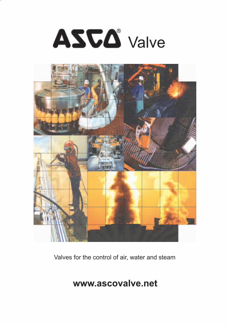
Valve Valves for the control of air, water and steam www.ascovalve.net
Transcript of GPV 4page brochure 2 - Dinafluid · Tel: (86-28) 8662 8833 Fax: (86-28) 8662 5854 Email:...
Valve
Valves for the control of air, water and steam
www.ascovalve.net

• Fluids : water, air & neutral gas; light oil < 40 cSt• Body : Brass• Sealing : NBR (steam: PTFE)• Maximum temperature
Ambient : +60 oC Fluid : +85 oC (106 Series : +80 oC)• Protection : IP65• Standard voltage DC (=) : 24V
AC (~) : 110V / 50-60 Hz220V / 50-60 Hz
230V / 50 Hz Other voltages available upon request
SOLENOID VALVESGENERAL PURPOSE APPLICATIONS
1/8” - 2”
TECHNICAL DATA
• Steam + 80 oC + 170 oC
106 series
238 series
240 series
Note: Manual Operator, Viton and EPDM can be suppliedConversion: Cv = 0.069kv (l/min) bar = 100kpa = 14.5psi oF = 9/5 oC + 32Viscosity: 40cSt = 186SSU
SPECIFICATIONS
minoperating pressure differential (bar)
maximumair / gas / water / light oil
AC(l/min)
flow coef
Kv- - - - - - - - - - - - - - - - - - - - - - - - - - - - AC DC
pipe
size
orifice
size(mm)
power
ratingG
DC
catalog
number- - - - - - - - - - - - - - - - - - -
(W) (W)
2 WAY NORMALLY CLOSED - STEAM / SUPERHEATED WATER
SCG240A100
SCG240A103
SCG240A102
SCG240A101
-
-
-
-
8
8
6
6
3/8”
1/2”
3/4”
1”
10
10
16
18.5
33
42
75
142
0.4
0.4
0.4
0.4
6
6
9
9
-
-
-
-
1/8”
1/8”
1/4”
1/4”
3/8”
3/8”
1/2”
1/2”
1/2”
1/2”
3/4”
3/4”
1”
1”
1 1/4”
1 1/2”
2”
1.5
2.5
1.5
2.5
12
12
12
12
15
15
20
20
25
25
30
45
45
2 WAY NORMALLY CLOSED12
4
12
4
10
16
10
16
10
16
10
16
10
16
10
10
10
20
10
20
10
10
16
10
16
10
16
10
16
10
16
10
10
10
1
1.7
1.1
2.9
40
40
40
40
70
70
110
110
165
165
250
450
566
0
0
0
0
0.3
0.3
0.3
0.3
0.3
0.3
0.3
0.3
0.3
0.3
0.5
0.5
0.5
4
4
4
4
4
5
4
5
4
5
4
5
4
5
6
6
6
6.9
6.9
6.9
6.9
6.9
6.9
6.9
6.9
6.9
6.9
6.9
6.9
6.9
6.9
9.5
9.5
9.5
10600058
10600187
10600003
10600189
SCE238A001
SCG238A016
SCG238A017
SCG238A018
SCE238A006
SCE238A002
SCE238B003
SCE238A004
SCE238A005
SCE238A007
SCE238B008
SCE238A009
SCE238A010
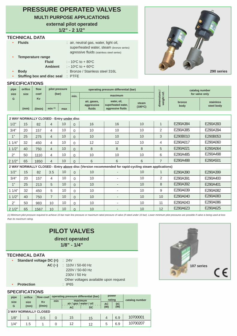
• Fluids : air, neutral gas, water, light oil,superheated water, steam (bronze series)
agressive fluids (stainless steel series)
• Temperature range Fluid : - 10oC to + 80oC
Ambient : - 10oC to + 60oC• Body : Bronze / Stainless steel 316L• Stuffing box and disc seal : PTFE
TECHNICAL DATA
(1) Minimum pilot pressure required to achieve 10 bar main line pressure or maximum rated pressure of valve (if rated under 10 bar). Lower minimum pilot pressures are possible if valve is being used at less
than its maximum rating.
PRESSURE OPERATED VALVESMULTI PURPOSE APPLICATIONS
external pilot operated1/2” - 2 1/2”
PILOT VALVESdirect operated
1/8” - 1/4”
SPECIFICATIONS
min
operating pressure differential (bar)
maximumair / gas / water / oil
(l/min)
flow coef
Kv- - - - - - - - - - - - - - - - -
3 WAY NORMALLY CLOSED
pipe
size
orifice
size(mm)
catalog number
powerrating
10700207
10700001
• Standard voltage DC (=) : 24V AC (~) : 110V / 50-60 Hz
220V / 50-60 Hz 230V / 50 Hz Other voltages available upon request• Protection : IP65
TECHNICAL DATA
AC DCAC DC
290 series
G
SPECIFICATIONS
(W) (W)
2 WAY NORMALLY CLOSED - Entry under disc
-----------------------------------------------------------------------
operating pressure differential (bar)
----
----
----water, oil,
superheated water,aggressive fluids
steam(180oC)
maximum
dim
ensi
on
s /
wei
gh
t re
f.
pipe
size
G
orifice
size
flow
coef
Kvmin.
air, gases,aggressive
fluids(mm) (l/min) ----
----
----
min (1) max
pilot pressure
(bar)
2 WAY NORMALLY CLOSED - Entry above disc (Version recommended for rapid-cycling steam applications)
catalog numberfor valve only
stainlesssteel body
E290A393
E290A394
E290A021 E290A064E290A498
E290A501
E290A399
E290A400
E290A401
E290A082E290A083
E290A086
E290A625
E290B053
E290A060
E290A384
E290A385
E290B010
E290A017
E290A485
E290A488
bronzebody
E290A040
E290A390
E290A391
E290A392
E290A039
E290A043E290A623
107 series
1/2”
3/4”
1”
1 1/4”
1 1/2”
2”
2 1/2”
15
20
25
32
40
50
65
82
157
275
450
750
1110
1850
4
4
4
4
4
4
4
10
10
10
10
10
10
10
0
0
0
0
0
0
0
16
10
10
12
8
10
6
16
10
10
12
8
10
6
10
10
10
10
8
10
6
1
2
3
4
5
6
7
1/2”
3/4”
1”
1 1/4”
1 1/2”
2”
2 1/2”
15
20
25
32
40
50
65
82
157
213
450
750
983
1567
3.5
4
5
5
7
10
10
10
10
10
10
10
10
10
0
0
0
0
0
0
0
10
10
10
10
10
10
10
-
-
-
-
-
-
-
10
10
10
10
10
10
10
1
2
8
9
10
11
12
1/8”
1/4”
1
1.5
0.5
1
0
0
15
12
15
12
4
5
6.9
6.9

DB
AE C
S
DIMENSIONS (mm), WEIGHT (kg)
C
A
D E
B
Pilot connection290 series
A B C D Eweight
142 69 155 65 27 1/ 8” 0.9169 159 75 32 1/ 8” 12
183 85 197 90 41 1/ 8” 1.73236 118 246 110 50 1/ 4” 2.74243 118 262 120 60 1/ 4” 3.55315 156 328 150 70 1/ 4” 6.86347 156 352 190 86 1/ 4” 8.17155 69 165 90 41 1/ 4” 1.48217 85 229 110 50 1/ 8” 2.19224 85 245 120 60 1/ 8” 2.910267 118 276 150 70 1/ 4” 4.311299 300 190 86 1/ 4” 6.312
151
118
pilotdimensions
290 seriesref G thread (kg)
----------------------------------------------------------------------------
----------------------------------------------------------------------------
----------------------------------------------------------------------------
----------------------------------------------------------------------------
catalog
numberA B C D E
weight
(kg)
A006 , A007
238 series
B003B008A004A009A005A010
81.5
95
105.5
62
84.5
95.5
105
82
57
68
87
43
71
79.5
84.5
68.5
28.5
34
43.5
21.50.50.50.60.80.91.01.1
0.4
A016A017A018
106 00 058106 00 003106 00 187
A100A101
113
145
33
40
6066
135142153
52
61
8085
81110110
60
60
4040
109112117
45
51
6972
40.55555
14
15
2020
1.72.62.9
0.14
0.17
0.380.41
A103
107 00 001107 00 207
79105
33
40
94.5123
5260
5071
2526.5
78102
45
50
2535.5
1111.5
0.611.34
0.1380.226
A001 , A002
140
106 series
----------------------------------------------------------------------------
240 series
A102
107 series
106 00 189
238 / 106 / 240 / 107 series
ASCO VALVE - ASIA / PACIFIC
AustraliaTel: (612) 9451 7077 Fax: (612) 9451 9924Email: [email protected]
BeijingTel: (86-10) 8563 1122 Fax: (86-10) 8561 5224Email: [email protected]
ChengduTel: (86-28) 8662 8833 Fax: (86-28) 8662 5854Email: [email protected]
GuangzhouTel: (86-20) 3877 1766 Fax: (86-20) 8761 6507Email: [email protected]
ShanghaiTel: (86-21) 6391 2588 Fax: (86-21) 6391 2319Email: [email protected]
Hong KongTel: (852) 2343 8580 Fax: (852) 2790 1771Email: [email protected]
New ZealandTel: (649) 478 0192 Fax: (649) 478 0193Email: [email protected]
SingaporeTel: (65) 6556 1100 Fax: (65) 6556 0011Email: [email protected]
South KoreaTel: (82-2) 515 2485 Fax: (82-2) 540 3250Email: [email protected]
TaiwanTel: (886-2) 2325 9555 Fax: (886-2) 2702 6009Email: [email protected]
China
Form: A2 (12/02)

CCaattaalloogg sshheeeettss

SOLENOID VALVESnormally closeddirect operated
1/8
1
2
NC
2
FEATURES● Compact design and low weight for easy installation● Manual operator as standard● Interchangeability of magnetic heads, AC and DC and for potentially explosive
atmospheres to EEx m (encapsulation)
GENERALDifferential pressure 0 to 20 bar [1 bar = 100 kPa]Maximum allowable pressure 20 barAmbient temperature range -10°C to +60°CMaximum viscosity 40 cSt (mm2/s)Response time 5 - 10 ms (with air ∆P = 6 bar)
temperature ranges sealingsfluids- 10°C to- 10°C to
+ 80°C+ 130°C
Water, air, neutral gas, light oilHydrocarbons
NBR (nitrile / buna-n)FPM (fluoroelastomer / viton)
2 1
CONSTRUCTIONBody BrassCore tube Stainless steelInternal parts Stainless steelSpring Stainless steelSeat BrassSealings NBR or FPMShading coil CopperCoil insulation class FConnector Spade plugConnector specification
for coil CM22-4W 3 x DIN 46244 (Pg 9P)for coil CM25-5W ISO 4400 (Pg 11P)
Electrical safety VDE 0580
V210-GB-R4
maximum
(m3/h)
(M)
catalogue number(~ / =)coil
type
~ / =
pipesize
G (mm)
flowcoefficient
Kv
(l/min)min.
~ =
water/oil=~ FPMNBR
106 00 004106 00 00120 20 20 20 CM22-4W ●
operating pressure differential(bar)
air/gas
orificesize
1 0,04 0,6 0
1,5 0,06 1 0106 00 064106 00 058●
106 00 244106 00 242●
CM22-4WCM25-5W
121520 15 20
20
2,5 0,10 1,7 0106 00 006106 00 003●
106 00 245106 00 243CM22-4WCM25-5W
414 7 14
4
12
10 10
20
7 ●
1/8
sealings
NC - normally closed operation, brass body
(°C)
coiltype
ambienttemperature
rangeprotection
(VA)
nominal power ratings
(W)(VA) (W)
holding~
inrush~
moulded IP65moulded IP65
-10 to +60-10 to +60
5 / 6,95 / 6,9
45
67
1215
CM22-4WCM25-5W (1)
=
SPECIFICATIONS
(M) Manual operator: ●: screwdriver(1) Coil CM25-5W is dual-voltage: (24V ~, 12V =) (48V ~, 24V =) (115V ~, 48V =) (230V ~, 110V =).
2/2Series
106
hot/coldhot/coldhot/coldhot/coldhot/cold
The codes in the grey shaded areas correspond to commonly used products which can be supplied rapidly
ELECTRICAL CHARACTERISTICSStandard voltages DC (=) : 24V(Other voltages and 60 Hz on request) AC (~) : 24V - 115V - 230V / 50 Hz
A
B
C
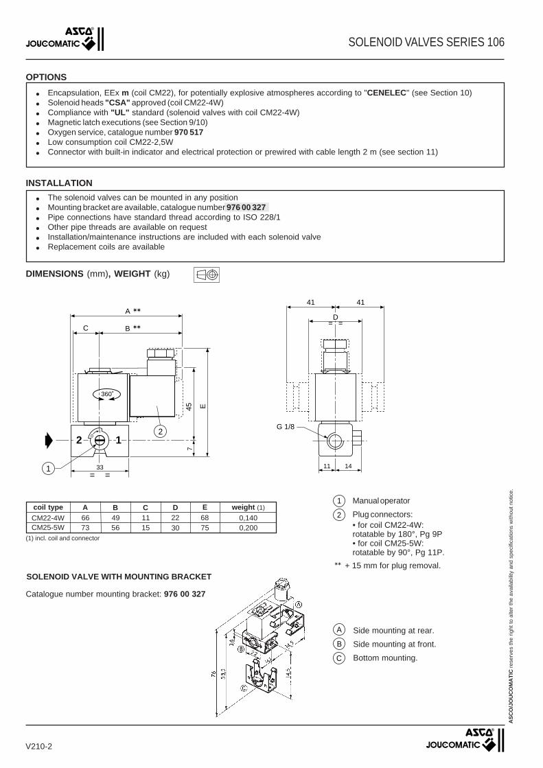
SOLENOID VALVES SERIES 106
OPTIONS
● Encapsulation, EEx m (coil CM22), for potentially explosive atmospheres according to "CENELEC" (see Section 10)● Solenoid heads "CSA" approved (coil CM22-4W)● Compliance with "UL" standard (solenoid valves with coil CM22-4W)● Magnetic latch executions (see Section 9/10)● Oxygen service, catalogue number 970 517● Low consumption coil CM22-2,5W● Connector with built-in indicator and electrical protection or prewired with cable length 2 m (see section 11)
Side mounting at rear.
Side mounting at front.
Bottom mounting.
360˚
INSTALLATION
● The solenoid valves can be mounted in any position● Mounting bracket are available, catalogue number 976 00 327● Pipe connections have standard thread according to ISO 228/1● Other pipe threads are available on request● Installation/maintenance instructions are included with each solenoid valve● Replacement coils are available
AS
CO
/JO
UC
OM
AT
IC r
eser
ves
the
right
to a
lter
the
avai
labi
lity
and
spec
ifica
tions
with
out n
otic
e.
7
33=
11
0
=14
41 41
= =
45 E
B
A ✶✶
✶✶
1
2G 1/8
C
2 11
D
Manual operator
Plug connectors:• for coil CM22-4W:rotatable by 180°, Pg 9P• for coil CM25-5W:rotatable by 90°, Pg 11P.
CM22-4W
coil type
(1) incl. coil and connector
1
2
CM25-5W66 49 1173 56 15 30
A B C
7522 68D E weight (1)
0,2000,140
✶✶ + 15 mm for plug removal.
Catalogue number mounting bracket: 976 00 327
SOLENOID VALVE WITH MOUNTING BRACKET
DIMENSIONS (mm), WEIGHT (kg)
V210-2

SOLENOID VALVESnormally closeddirect operated
1/4
1
2
NC
2
FEATURES● Compact design and low weight for easy installation● Interchangeability of magnetic heads, AC and DC and for potentially explosive
atmospheres to EEx m (encapsulation)
2 1
2/2Series
106
GENERALDifferential pressure 0 to 20 bar [1 bar = 100 kPa]Maximum allowable pressure 20 barAmbient temperature range -10°C to +60°CMaximum viscosity 40 cSt (mm2/s)Response time 5 - 10 ms (with air ∆P = 6 bar)
temperature ranges sealingsfluidsWater, air, neutral gas, light oilHydrocarbons
- 10°C to- 10°C to
+ 80°C+130°C
NBR (nitrile / buna-n)FPM (fluoroelastomer / viton)
CONSTRUCTIONBody BrassCore tube Stainless steelInternal parts Stainless steelSpring Stainless steelSeat BrassSealings NBR or FPMShading coil CopperCoil insulation class FConnector Spade plugConnector specification
for coil CM22-4W 3 x DIN 46244 (Pg 9P)for coil CM25-5W ISO 4400 (Pg 11P)
Electrical safety VDE 0580
V230-GB-R4
SPECIFICATIONS
(m3/h)
(M)
catalogue number(~ / =)
sealings
~ / =
pipesize
(G*) (mm)
flowcoefficient
Kv
(l/min)min.
~ =
water/oil
=~ FPMNBR
operating pressure differential(bar)
air/gas
orificesize
(°C)
coiltype
ambienttemperature
rangeprotection
(VA)
nominal power ratings
(W)(VA) (W)
holding~
inrush~
moulded IP65moulded IP65
-10 to +60-10 to +60
5 / 6,95 / 6,9
45
67
1215
CM22-4WCM25-5W
maximumcoiltype
(1)
106 00 191106 00 18620 20 20 20 CM22-4W1 0,04 0,6 0
1,5 0,07 1,12 0106 00 192106 00 187●
106 00 259106 00 257●
CM22-4W121520 15 20
20
2,5 0,17 2,85 0106 00 194106 00 189●
106 00 260106 00 258CM22-4WCM25-5W
414 7 14
4
12
10 10
20
7
106 00 143106 00 1365 0,39 6,5 0 3 1 3 1 CM25-5W ✕
●
CM25-5W
106 00 142106 00 1354 0,30 5 0 5 1,5 5 1,5 CM25-5W ✕
●
1/4
(M) Manual operator: ✕: without ●: screwdriver.(1) Coil CM25-5W is dual-voltage: (24V ~, 12V =) (48V ~, 24V =) (115V ~, 48V =) (230V ~, 110V =).
=hot/cold
The codes in the grey shaded areas correspond to commonly used products which can be supplied rapidly
ELECTRICAL CHARACTERISTICSStandard voltages DC (=) : 24V(Other voltages and 60 Hz on request) AC (~) : 24V - 115V - 230V / 50 Hz

OPTIONS
● Encapsulation, EEx m (coils CM22), for potentially explosive atmospheres according to "CENELEC" (see Section 10)● Solenoid heads "CSA" approved (coil CM22-4W)● Oxygen service, catalogue number 970 517● Connector with built-in indicator and electrical protection or prewired with cable length 2 m (see Section 11)
SOLENOID VALVES SERIES 106
AS
CO
/JO
UC
OM
AT
IC r
eser
ves
the
right
to a
lter
the
avai
labi
lity
and
spec
ifica
tions
with
out n
otic
e.
V230-2
68 49 1176 56 15 30
A B C
8322 79D E weight (1)
0,2300,170
(1) incl. coil and connector
Manual operator (except dia. 4 and 5)
Plug connectors:• for coil CM22-4W:rotatable by 180°, Pg 9P• for coil CM25-5W:rotatable by 90°, Pg 11P
Mounting: two M4, depth 5 holes
10
41 41
= =
50 E
B
A ✶✶
✶✶
1
1/4
C
40= = = =
15
1511,5
D
0
1
2 12
3
360˚
INSTALLATION
● The solenoid valves can be mounted in any position● These valves have 2 mounting holes in the body● Pipe connections (G*) have standard combination thread according to ISO 228/1 and ISO 7/1● Other pipe threads are available on request● Installation/maintenance instructions are included with each solenoid valve● Replacement coils are available
coil typeCM22-4WCM25-5W
DIMENSIONS (mm), WEIGHT (kg)
✶✶ + 15 mm for plug removal.
1
2
3

All leaflets are available on: www.ascojoucomatic.com
-10 to +85°C NBR (nitrile / buna-n))DN ≤ 25: air, inert gas and water
DN > 25: air and water
SOLENOID VALVESnormally closed, built-in pilot
pilot operated, floating diaphragm3/8 to 2
NC
3
FEATURES●●●●● Solenoid valves satisfy all relevant EC directives● Minimum operating pressure differential 0.3 / 0.5 bar● Interchangeability of magnetic heads, AC and DC
V316-GB-R5a
GENERALDifferential pressure See "SPECIFICATIONS" (1 bar = 100 kPa)Ambient temperature range -10°C to +60°CMaximum viscosity 40 cSt (mm2/s)Response time (Air operation, ∆P = 6 bar) 3/8 1/2 3/4 1 1 1/4 1 1/2 2
opening time (ms) 25 30 55 70 300 300 1500closing time (ms) 40 90 110 200 1000 1000 2000
2/2
238Series
MATERIALS IN CONTACT WITH FLUID(✷) Ensure that the compatibility of the fluids in contact with the materials is verifiedBody BrassInternal parts Stainless steel and brassSprings Stainless steelSeals, diaphragm and disc NBRShading coil Copper
ELECTRICAL CHARACTERISTICSCoil isolation class FConnector Spade plugConnector specification
for CM22-4W 3 x DIN 46244 (Pg 9P)for CM25-5W / AMX ISO 4400 (Pg 11P)
Electrical safety VDE 0580Standard voltages DC (=): 24V(Other voltages and 60 Hz on request) AC (~): 24V - 115V - 230V / 50 Hz
(°C)
ambienttemperaturerange (TS)
(VA)
nominal power ratingscoiltype
protection
moulded IP65
hot/cold=
inrush~
holding~
(VA) (W) (W)
-10 to +605 / 6,95 / 6,9
7,5 / 9,5
456
6710
121520
CM22-4WCM25-5WAMX
The codes in the grey shaded areas correspond to commonly used products which can be supplied rapidly
temperature range (TS) sealings (✷)fluids (✷)
(mm) (m3/h) (l/min)min. air (✷) water (✷)
maximum (PS)
~ ~/=
operating pressure differential(bar)flow
coefficientKv
G* 3/8G* 3/8G* 1/2G* 1/2G* 1/2G* 1/2G* 3/4G* 3/4G* 1G* 1
G 1 1/4G 1 1/2
G 2
= ~ =
12121212151520202525304545
2,42,42,42,44,24,26,66,69,99,9152734
40 40 40 40 70 70110110165165250450566
0,30,30,30,30,30,30,30,30,30,30,50,50,5
10161016101610161016101010
10161016101610161016101010
10161016101610161016101010
10161016101610161016101010
CM22-4WCM25-5WCM22-4WCM25-5WCM22-4WCM25-5WCM22-4WCM25-5WCM22-4WCM25-5W
AMXAMXAMX
pipesize
orificesize
coil type
SPECIFICATIONS
FP
M
EP
DM
catalogue number
NBRsealings
SC E238A001SC E238A006SC E238A002SC E238A007SC E238B003SC E238B008SC E238A004SC E238A009SC E238A005SC E238A010SC G238A016SC G238A017SC G238B018
OPTIONAL
VVVVVVVVVVVVV
EEEEEEEEEE---

All leaflets are available on: www.ascojoucomatic.com
A B C
E HJ
K
DG
360˚
F
SOLENOID VALVES SERIES 238
OPTIONS
●●●●● Valves can also be supplied with FPM (fluorelastomer / viton), EPDM (ethylene-propylene) sealings, diaphragm and disc.Use the appropriate optional suffix letter for identification
●●●●● Manual operator, suffix MOVersions 3/8 to 1:
● Explosionproof EEx m coil for hazardous areas (only for versions with coil CM22-4W); see V1037 (section 10)●●●●● Compliance with "UL" and "CSA" standards (catalogue numbers A001/A002/B003/A004/A005 only, optional)●●●●● Magnetic latch execution for CM22 coil type only; see V910-10 (Section 9/10)
All versions:● Connectors with built-in indicator and electrical protection or prewired with cable length 2 m (see section 11)
V316-2
(1) Incl. coil and connector (2) Manual operated (option) (3) Manual operated, added +23 mm (C) Construction type
AS
CO
/JO
UC
OM
AT
IC r
eser
ves
the
right
to a
lter
the
avai
labi
lity,
des
ign
and
spec
ifica
tions
with
out n
otic
e.
Fig. 1 Fig. 2
(2) (2)
DIMENSIONS (mm), WEIGHT (kg)
INSTALLATION
● Solenoid valves can be mounted in any position without affecting operation● Pipe connections (G*) have standard combination thread according to ISO 228/1 and ISO 7/1. Pipe connections (G)
have standard combination thread according to ISO 228/1● The third digit in the catalogue number indicates the standard pipe connection: E= ISO 228/1 and ISO 7/1● Other pipe connections are available on request● Installation/maintenance instructions are included with each valve● Spare parts kits and replacement coils are available (see section 11)
catalogue number Ø A C E G
SC E238A001SC E238A002SC E238B003SC E238A004SC E238A005SC E238A006SC E238A007SC E238B008SC E238A009SC E238A010SC G238A016SC G238A017SC G238B018
2222222222
1111111111
B
4949494949
D
959597108118
4343576887
F
3/81/21/23/41
3/81/21/23/41
1 1/41 1/2
2
H K
58,558,574,586,594
J
6262
81,595
105,5
weight (1)
68,568,571
79,584,5
8282
84,595,5105
34,534,545,55358
3030303030323232
1515151515161616
5757575757575757
96,596,599110
119,5150157168
434357688781110110
62,562,578,590,598106129129
6262
81,595
105,5113140157
68,568,571
79,584,5
109 (3)112 (3)117 (3)
8282
84,595,5105
135 (3)142 (3)153 (3)
34,534,545,55358638085
(C)
fig. 1
fig. 2
0,40,40,50,81,00,50,50,60,91,11,72,62,9
fig. 3
B
FG
D
E HJK
A C
360˚
B C
D
E
FG
HJK
A
360˚
Fig. 3

All leaflets available on: www.ascojoucomatic.com
air and water
SOLENOID VALVESnormally open, built-in pilot
pilot operated, floating diaphragm1 1/4 to 2
NO
3
FEATURES●●●●● Solenoid valves satisfy all relevant EC directives● Two way normally open valves for automatic control of water, air and inert
gas and other gases/liquids compatible with the sealing materials used● Minimum operating pressure differential 0.3 bar● Interchangeability of magnetic heads, AC and DC
V393-GB-R1
GENERALDifferential pressure 0,5 to 10 bar (1 bar = 100 kPa)Ambient temperature range -10°C to +60°CMaximum viscosity 40 cSt (mm2/s)Response time (Air operation, ∆P = 6 bar) 1 1/4 1 1/2 2
opening time (ms) 300 300 1500closing (ms) 1000 1000 2000
fluids (✷) temperature range (TS) sealings (✷)NBR (nitrile / buna-n)-10°C to +85°C
2/2
238Series
MATERIALS IN CONTACT WITH FLUID(✷) Ensure that the compatibility of the fluids in contact with the materials is verifiedBody BrassInternal parts Stainless steel and brassSprings Stainless steelSeals, diaphragm and disc NBRShading coil Copper
(°C)
ambienttemperaturerange (TS)
(VA)
nominal power ratingscoiltype
protection
moulded IP65
hot/cold=
(G) (mm) (m3/h) (l/min)min. air (✷) water (✷)
maximum (PS)
~ ~/=
operating pressure differential(bar)flow
coefficientKv
1 1/41 1/2
2
= ~ =
304545
152734
250450566
0,50,50,5
101010
101010
101010
101010
AMXAMXAMX
pipesize
orificesize coil type
SPECIFICATIONS
inrush~
holding~
(VA) (W) (W)
-10 to +607,5 / 9,561020AMXF
PM
catalogue number
NBRsealings
SC G238A019SC G238A020SC G238B021
OPTIONAL
VVV
ELECTRICAL CHARACTERISTICSCoil isolation class FConnector Spade plugConnector specification ISO 4400Electrical safety VDE 0580Standard voltages DC (=) : 24V(Other voltages and 60 Hz on request) AC (~) : 24V - 115V - 230V / 50 Hz
The codes in the grey shaded areas correspond to commonly used products which can be supplied rapidly
All leaflets available on: www.ascojoucomatic.com
SOLENOID VALVES SERIES 238
OPTIONS
V393-2
AS
CO
/JO
UC
OM
AT
IC r
eser
ves
the
right
to a
lter
the
avai
labi
lity,
des
ign
and
spec
ifica
tions
with
out n
otic
e.
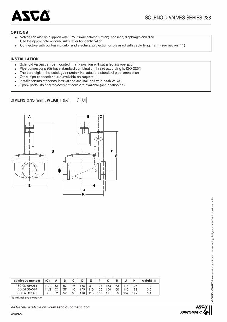
DIMENSIONS (mm), WEIGHT (kg)
INSTALLATION
●●●●● Valves can also be supplied with FPM (fluorelastomer / viton) sealings, diaphragm and disc.Use the appropriate optional suffix letter for identification
● Connectors with built-in indicator and electrical protection or prewired with cable length 2 m (see section 11)
● Solenoid valves can be mounted in any position without affecting operation● Pipe connections (G) have standard combination thread according to ISO 228/1● The third digit in the catalogue number indicates the standard pipe connection● Other pipe connections are available on request● Installation/maintenance instructions are included with each valve● Spare parts kits and replacement coils are available (see section 11)
(1) Incl. coil and connector
catalogue number (G) A C E G
SC G238A019SC G238A020SC G238B021
323232
161616
B
575757
D
168175186
81110110
F
1 1/41 1/2
2
H K
106129129
J
113140157
weight (1)
127130135
153160171
638085
1,93,03,4
A B C
E HJ
K
360˚
FDG
4
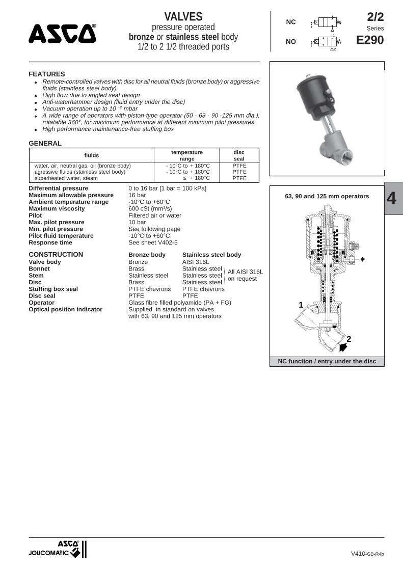
NC function / entry under the disc
2/2Series
E290
NC
NO1
2
V410-GB-R4b
63, 90 and 125 mm operators
1
2
GENERAL
fluids temperaturerange
discsealPTFEPTFEPTFE
- 10°C to + 180°C- 10°C to + 180°C
≤ + 180°C
water, air, neutral gas, oil (bronze body)agressive fluids (stainless steel body)superheated water, steam
FEATURES● Remote-controlled valves with disc for all neutral fluids (bronze body) or aggressive
fluids (stainless steel body)● High flow due to angled seat design● Anti-waterhammer design (fluid entry under the disc)● Vacuum operation up to 10 - 2 mbar● A wide range of operators with piston-type operator (50 - 63 - 90 -125 mm dia.),
rotatable 360°, for maximum performance at different minimum pilot pressures● High performance maintenance-free stuffing box
VALVESpressure operated
bronze or stainless steel body1/2 to 2 1/2 threaded ports
Differential pressure 0 to 16 bar [1 bar = 100 kPa]Maximum allowable pressure 16 barAmbient temperature range -10°C to +60°CMaximum viscosity 600 cSt (mm2/s)Pilot Filtered air or waterMax. pilot pressure 10 barMin. pilot pressure See following pagePilot fluid temperature -10°C to +60°CResponse time See sheet V402-5
CONSTRUCTION Bronze body Stainless steel bodyValve body Bronze AISI 316LBonnet Brass Stainless steelStem Stainless steel Stainless steelDisc Brass Stainless steelStuffing box seal PTFE chevrons PTFE chevronsDisc seal PTFE PTFEOperator Glass fibre filled polyamide (PA + FG)Optical position indicator Supplied in standard on valves
with 63, 90 and 125 mm operators
All AISI 316Lon request

V410-2
VALVES SERIES E290
SPECIFICATIONS
The codes in the grey shaded areas correspond to commonly used products which can be supplied rapidly
pipesize min.
(m3/h)(G*) (mm) (l/min) min. max.
watersuperheated water
oilaggressive liquids
airgases
aggressivefluids
flowcoefficient
Kv
pilotpressure
(bar)
maximum catalogue numberfor valve only
(mm)
operatordiameter
orificesize
operating pressure differential (bar)
STAINLESSSTEEL BODY
BRONZEBODY
steam(180°C)
(❉) Minimum pilot pressure varies with differential pressure, see V402-5(1) Minimum pilot pressure 1,5 and 2,5 bar, optional
Calculation of the minimum pilot pressure with backpressure acceptable, within ∆P max. 10 bar (not recommended with liquids as waterhammer effect).• 50 mm operator: 4 bar minimum pilot pressure version: add 2 bar to the minimum pilot pressure of Chart V, page V402-5.• 63, 90 and 125 mm operators: 4 bar minimum pilot pressure version: add 1,5 bar to the minimum pilot pressure of Chart VI, VII or VIII, page V402-5.
94 1567
48 800
45 750
4 10 0 16 16 10 50 E290A384 E290A3934 10 0 10 10 10 50 E290A385 E290A3944 10 0 16 16 10 63 E290B005 E290B0484 10 0 6 6 6 50 E290A386 E290A3954 10 0 10 10 10 63 E290B010 E290B0534 10 0 16 16 10 90 E290B011 E290B0544 10 0 6 6 6 63 E290A016 E290A0594 10 0 12 12 10 90 E290A017 E290A0604 10 0 16 16 10 125 E290A642 E290A6464 10 0 4 4 4 63 E290A020 E290A0634 10 0 8 8 8 90 E290A021 E290A0644 10 0 16 16 10 125 E290A482 E290A4954 10 0 2,5 2,5 2,5 63 E290A024 E290A0674 10 0 6 6 6 90 E290A025 E290A0684 10 0 10 10 10 125 E290A485 E290A4984 10 0 2 2 2 90 E290A487 E290A5004 10 0 6 6 6 125 E290A488 E290A501
V 10 0 10 - 10 50 E290A390 E290A399V 10 0 10 - 10 50 E290A391 E290A400VI 10 0 10 - 10 63 E290B037 E290B080V 10 0 10 - 10 50 E290A392 E290A401VI 10 0 10 - 10 63 E290B038 E290B081VI 10 0 10 - 10 63 E290A039 E290A082VII 10 0 10 - 10 90 E290A136 E290A137VI 10 0 10 - 10 63 E290A040 E290A083VII 10 0 10 - 10 90 E290A041 E290A084VI 10 0 9 - 9 63 E290A042 E290A085VII 10 0 10 - 10 90 E290A043 E290A086VII 10 0 10 - 10 90 E290A623 E290A625
1/2 15 4,9 82
3/4 20 9,4 157
1 25
1 1/4 32 27 450
2 50
I 10 0 16 16 10 50 E290A387 E290A396I 10 0 16 16 10 50 E290A388 E290A397II 10 0 16 16 10 63 E290B027 E290B070I 10 0 16 16 10 50 E290A389 E290A398II 10 0 16 16 10 63 E290B028 E290B071III 10 0 16 16 10 90 E290B029 E290B072II 10 0 16 16 10 63 E290A030 E290A073III 10 0 16 16 10 90 E290A031 E290A074II 10 0 11 11 10 63 E290A032 E290A075III 10 0 16 16 10 90 E290A033 E290A076IV 10 0 16 16 10 125 E290A489 E290A502II 10 0 7 7 7 63 E290A034 E290A077III 10 0 13 13 10 90 E290A035 E290A078IV 10 0 16 16 10 125 E290A490 E290A503III 10 0 7 7 7 90 E290A491 E290A504IV 10 0 16 16 10 125 E290A492 E290A505
1/2 15 4,9 82
3/4 20 9,4 157
1 1/4 32 27 450
1/2 15 4,9 82
3/4 20 9,4 157
(❉)1 1/4 32 27 450
(❉)
(❉)
1 1/2 40 45 750
2 50 59 983
(❉)
(❉)
(❉)
(❉)
(❉)
(❉)
(❉)
(❉)
(❉)
16,5 275
12,8 213
1 25 16,5 275
12,8 213 (❉)
1 2516,5 27512,8 213
(❉)
2 1/2 65
(❉)
(❉)2 1/2 65 94 1567
59 983
66 1100
111 1850
2 50
2 1/2 65
59 983
1 1/2 40
48 800
45 7501 1/2 40
94 156766 1100
111 1850
29 483
NC - normally closed - entry above disc (Version recommended for rapid-cycling steam applications)
NO - normally open - entry under disc
NC - normally closed - entry under disc (1)
(❉)
(❉)
(❉)
4
VALVES SERIES E290
V410-3
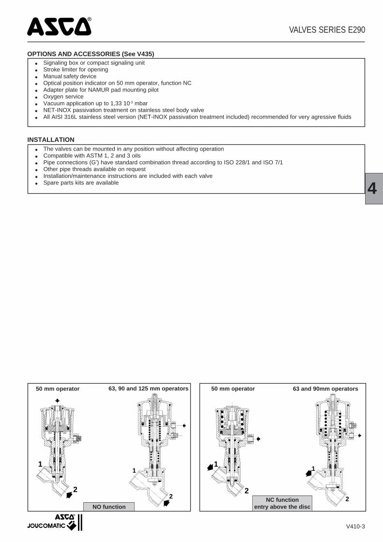
● The valves can be mounted in any position without affecting operation● Compatible with ASTM 1, 2 and 3 oils● Pipe connections (G*) have standard combination thread according to ISO 228/1 and ISO 7/1● Other pipe threads available on request● Installation/maintenance instructions are included with each valve● Spare parts kits are available
INSTALLATION
1
2
1
2
1
2
NO functionNC function
entry above the disc
50 mm operator 63, 90 and 125 mm operators 63 and 90mm operators50 mm operator
1
2
OPTIONS AND ACCESSORIES (See V435)● Signaling box or compact signaling unit● Stroke limiter for opening● Manual safety device● Optical position indicator on 50 mm operator, function NC● Adapter plate for NAMUR pad mounting pilot● Oxygen service● Vacuum application up to 1,33 10-3 mbar● NET-INOX passivation treatment on stainless steel body valve● All AISI 316L stainless steel version (NET-INOX passivation treatment included) recommended for very agressive fluids

Ø A B C D E ØF G H weight (1)1/2 142 154,5 141 65 69 43 27 0,93/4 150,5 159 143 75 69 43 32 11 155 165 145 90 69 43 41 1,4
V410-4
AS
CO
/JO
UC
OM
AT
IC r
eser
ves
the
right
to a
lter
the
avai
labi
lity,
des
ign
and
spec
ifica
tions
with
out n
otic
e.
DIMENSIONS (mm), WEIGHT (kg)
VALVES SERIES E290
Construction with 50 mm operator
NC and NO valvesentry under disc at 2entry above disc at 1
Construction with 63 mm operator Construction with 90 mm operator
Construction with 125 mm operator
50 mm operator
63, 90 or 125 mm operator
Ø A B C D E ØF G H weight (1)1/2 170 183 169 65 85 50,5 27 1,23/4 175 186 170 75 85 50,5 32 1,31 183 197 177 90 85 50,5 41 1,7
1 1/4 217 229 204 110 85 50,5 50 2,11 1/2 224 245 215 120 85 50,5 60 2,9
2 249 259 224 150 85 50,5 70 3,7
Ø A B C D E ØF G H weight (1)1 204 217 197 90 118 67 41 2,3
1 1/4 236 246 221 110 118 67 50 2,71 1/2 243 262 232 120 118 67 60 3,5
2 267 276 241 150 118 67 70 4,32 1/2 299 300 257 190 118 67 86 6,3
Ø A B C D E ØF G H weight (1)1 1/4 284 298 273 110 156 86 50 5,21 1/2 291 313,5 283,5 120 156 86 60 6,0
2 315 328 293 150 156 86 70 6,82 1/2 347 352 308 190 156 86 86 8,9
1/8
Ø A H
Ø F
360˚C D
50˚
EB
G
360˚
C
D
H EB
50˚
Ø F
Ø A
G
2
(1) Weight of valve without pilot. Pilot solenoid valves, see V440 (63 mm operator)
V443 (90 - 125 mm operators)
Pilot port• 1/8 (with 63 mm operator)• 1/4 (with 90 or 125 mm operator)
2
5
NC
NO
3/2Series
107
2
3 12
13
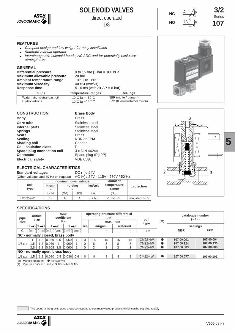
FEATURES● Compact design and low weight for easy installation● Standard manual operator● Interchangeable solenoid heads, AC / DC and for potentially explosive
atmospheres
GENERALDifferential pressure 0 to 15 bar [1 bar = 100 kPa]Maximum allowable pressure 20 barAmbient temperature range -10°C to +60°CMaximum viscosity 40 cSt (mm2/s)Response time 5-10 ms (with air ∆P = 6 bar)
temperature ranges sealingsfluidsWater, air, neutral gas, oilHydrocarbons
NBR (nitrile / buna-n)FPM (fluoroelastomer / viton)
-10°C to-10°C to
+ 80°C+130°C
3
2 1
SOLENOID VALVESdirect operated
1/8
CONSTRUCTION Brass BodyBody BrassCore tube Stainless steelInternal parts Stainless steelSprings Stainless steelSeats BrassSealing NBR or FPMShading coil CopperCoil insulation class FSpade plug connection coil 3 x DIN 46244Connector Spade plug (Pg 9P)Electrical safety VDE 0580
(°C)(VA) (W)(VA) (W)
coil type
ambienttemperature
rangeprotection
nominal power ratingsinrush
~ =holding
~
SPECIFICATIONS
4CM22-4W -10 to +605 / 6,9612 moulded IP65
(M) Manual operator: ●: screwdriver(1) Pipe size orifices 1 and 2: G 1/8, orifice 3: M5.
(M)
NBR
coiltype
operating pressure differential(bar)maximum
air/gasmin.
catalogue number(~ / =)
sealings1➞2 2➞3 1➞2 2➞3FPMG (m3/h)(l/min) (m3/h)(l/min)(mm)(mm)
water/oil=~~ =
NC - normally closed, brass body1 1,2 0,030 0,5 0,060 1 0 15 15 15 15
1,5 1,2 0,060 1 0,060 1 0 8 8 8 82,5 1,2 0,108 1,8 0,060 1 0 3 3 3 3
●●●
107 00 004107 00 130107 00 006
CM22-4WCM22-4WCM22-4W
107 00 001107 00 124107 00 003
1/8 (1)
orificesizepipe
size
flowcoefficient
Kv
NO - normally open, brass body1,5 1,2 0,030 0,5 0,036 0,6 0 8 8 8 8 ●CM22-4W 107 00 077 107 00 1011/8 (1)
V505-GB-R4
hot/cold
The codes in the grey shaded areas correspond to commonly used products which can be supplied rapidly
ELECTRICAL CHARACTERISTICSStandard voltages DC (=) : 24V(Other voltages and 60 Hz on request) AC (~) : 24V - 115V - 230V / 50 Hz
~ / =

SOLENOID VALVES SERIES 107
SOLENOID VALVE WITH MOUNTING BRACKET
Mounting bracket catalogue number: 976 00 327
ACCESSORIES AND OPTIONS
INSTALLATION
(1) Incl. coil and connector
DIMENSIONS (mm), WEIGHT (kg)
Side mounting at rear
Side mounting at front
Bottom mounting
A
B
C
Manual operator
Plug connector:size 22 rotatable by 180°, Pg 9P
Port 3 fitting M5, depth 5,5
1
2
✶✶ + 15 mm for plug removal
3
CM22-4W
coil type weight (1)
0,138
7
33=
11
0
=14
= =
45 68
49
66 ✶✶
✶✶
1
2G 1/8
11
2 11
22
360˚
33
Inlet pressure:
● NC operation = port 1
● NO operation = port 3 (M5)
AS
CO
/JO
UC
OM
AT
IC r
eser
ves
the
right
to a
lter
the
avai
labi
lity
and
spec
ifica
tions
with
out n
otic
e
● The solenoid valves can be mounted in any position● Mounting bracket are available, catalogue number 976 00 327● Pipe connections G 1/8 have standard thread according to ISO 228/1● Other pipe threads are available on request● Installation/maintenance instructions are included with each solenoid valve● Replacement coils are available
● Encapsulation, EEx m (coils CM22), for explosive atmospheres according to "CENELEC" (see Section 10)● Solenoid heads "CSA" approved● Compliance with "UL" standard● Magnetic latch executions (see Section 9/10)● Oxygen service, catalogue number 970 517● Low consumption coil CM 22-2,5W● Connector with built-in indicator and electrical protection or prewired with cable length 2 m (see Section 11)● Exhaust port regulator M5 adaptable on port 3, catalogue number 346 00 380
V505-2

SOLENOID VALVESdirect operated
1/4NC
3/2Series
107
CONSTRUCTIONBody BrassCore tube Stainless steelInternal parts Stainless steelSprings Stainless steelSeats BrassSealings NBR or FPMShading coil CopperCoil insulation class FConnector Spade plug (Pg 11P)Connector specification ISO 4400Electrical safety VDE 0580
temperature ranges sealingsfluidsWater, air, neutral gas, light oilHydrocarbons
-10°C to-10°C to
+ 80°C+130°C
NBR (nitrile / buna-n)FPM (fluoroelastomer / viton)
2
3 1
5
2 1
3
FEATURES● Compact design and low weight for easy installation● Manual operator as standard● Interchangeability of magnetic heads, AC and DC
GENERALDifferential pressure 0 to 15 bar [1 bar = 100 kPa]Maximum allowable pressure 20 barAmbient temperature range -10°C to +60°CMaximum viscosity 40 cSt (mm2/s)Response time 5-10 ms (with air ∆P = 6 bar)
(°C)
coiltype
ambienttemperature
rangeprotection
(VA)
nominal power ratings
(W)(VA) (W)
holding~
inrush~ =
-10 to +605 / 6,95715CM25-5W (1) moulded IP65
SPECIFICATIONS
(M)
NBR
coil type
operating pressure differential(bar)maximum
air/gasmin.
pipesize
catalogue number(~ / =)
sealings2➞3 1➞2 2➞3FPM(G*) (m3/h) (l/min) (m3/h)(mm)(mm)
water/oil=~~ =
●●●
107 00 209107 00 210107 00 211
CM25-5WCM25-5WCM25-5W
107 00 206107 00 207107 00 208
1 1,5 0,030 0,5 0,075 1,25 0 15 15 15 151,5 1,5 0,060 1 0,075 1,25 0 12 12 12 122,5 1,5 0,144 2,4 0,075 1,25 0 5 5 5 5
(M) Manual operator: ●: screwdriver(1) Coil CM25-5W is dual-voltage: (24V ~, 12V =) (48V ~, 24V =) (115V ~, 48V =) (230V ~, 110V =).(2) Pipe size orifices 1 and 2: 1/4, orifice 3: M5.
1➞2
flowcoefficient
Kv
1/4 (2)
orifice size
(l/min)
V540-GB-R4
hot/cold
The codes in the grey shaded areas correspond to commonly used products which can be supplied rapidly
ELECTRICAL CHARACTERISTICSStandard voltages DC (=) : 24V(Other voltages and 60 Hz on request) AC (~) : 24V - 115V - 230V / 50 Hz
~ / =
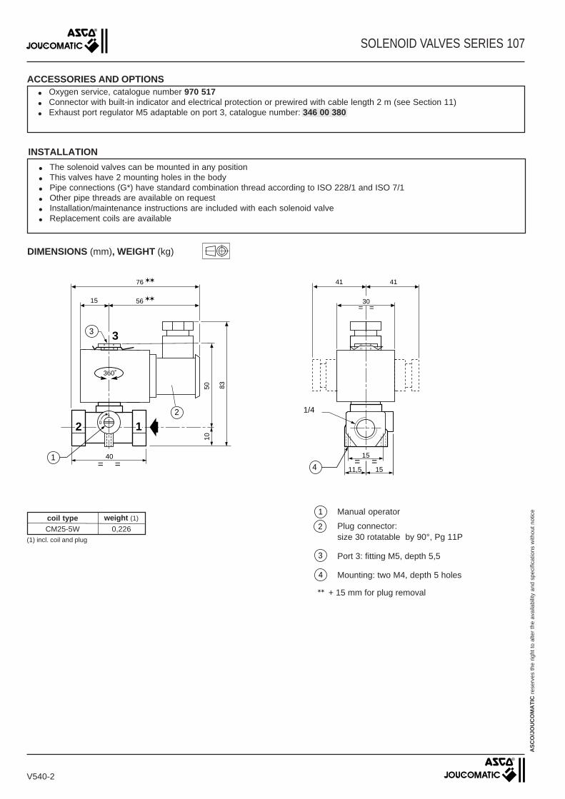
Manual operator
Plug connector:size 30 rotatable by 90°, Pg 11P
Port 3: fitting M5, depth 5,5
Mounting: two M4, depth 5 holes
SOLENOID VALVES SERIES 107
ACCESSORIES AND OPTIONS● Oxygen service, catalogue number 970 517● Connector with built-in indicator and electrical protection or prewired with cable length 2 m (see Section 11)● Exhaust port regulator M5 adaptable on port 3, catalogue number: 346 00 380
AS
CO
/JO
UC
OM
AT
IC r
eser
ves
the
right
to a
lter
the
avai
labi
lity
and
spec
ifica
tions
with
out n
otic
e
INSTALLATION
● The solenoid valves can be mounted in any position● This valves have 2 mounting holes in the body● Pipe connections (G*) have standard combination thread according to ISO 228/1 and ISO 7/1● Other pipe threads are available on request● Installation/maintenance instructions are included with each solenoid valve● Replacement coils are available
DIMENSIONS (mm), WEIGHT (kg)
10
41 41
= =
50 83
56
76 ✶✶
✶✶
1
1/4
15
40= = = =
15
1511,5
30
0
1
2 1
3
360˚
2
3
4
coil typeCM25-5W
(1) incl. coil and plug
weight (1)
0,226
1
2
3
✶✶ + 15 mm for plug removal
4
V540-2

All leaflets are available on: www.ascojoucomatic.com
905
~
superheated water - steam
SOLENOID VALVESnormally closed, pilot operated
for superheated water/steam applications3/8 to 1
NC
FEATURES●●●●● Solenoid valves satisfy all relevant EC directives● Two-way normally closed valves for automatic control of superheated water /
steam, air and inert gas and other gases/liquids compatible with the sealingmaterials used
● Minimum operating differential pressure 0.4 bar
V905-21-GB-R1
GENERALDifferential pressure 0,4 to 8 bar (1 bar = 100 kPa)Maximum viscosity 37 cSt (mm2/s)Response time 100 to 1500 ms
fluids (✷) temperature range (TS) sealings (✷)
reinforced PTFE (rulon)+60°C to +170°C
2/2
240Series
MATERIALS IN CONTACT WITH FLUID(✷) Ensure that the compatibility of the fluids in contact with the materials is verifiedBody BrassInternal parts Stainless steel and brassSprings Stainless steelSeals, diaphragm PTFEDisc Reinforced PTFESeating Stainless steelShading coil Copper
ELECTRICAL CHARACTERISTICSCoil isolation class HConnector Spade plugConnector specification
for BMX 3 x DIN 46244 (Pg 9P)for AMX ISO 4400 (Pg 11P)
Electrical safety VDE 0580Standard voltages(Other voltages and 60 Hz on request) AC (~) : 24V - 115V - 230V / 50 Hz
SPECIFICATIONS
pipesize
orificesize
flowcoefficient
Kv
operating pressuredifferential (bar)
(l/min)(m3/h)
maximum (PS)
(°C)steam
(✷)water
(✷)
min.
(mm)
10 1016
18,5
22,54,58,5
33,341,675,0141,6
0,40,40,40,4
8866
8866
170170170170
BMXBMXAMXAMX
3/81/23/41
(1) Min. fluid temperature: + 60°C.
SC G240A100 SC G240A101 SC G240A102 SC G240A103
max.fluidtemp.
(1)
coil type catalogue number
(G)
(°C)
ambienttemperaturerange (TS)
(VA)
nominal power ratingscoiltype
protection
moulded IP65
hot/cold=
inrush~
holding~
(VA) (W) (W)
-10 to +80--
66
1014
1623
BMXAMX
The codes in the grey shaded areas correspond to commonly used products which can be supplied rapidly

All leaflets are available on: www.ascojoucomatic.com
SOLENOID VALVES SERIES 240
OPTIONS
● Connectors with built-in indicator and electrical protection or prewired with cable length 2 m (see section 11)
V905-21-2
(1) Incl. coil and connector
AS
CO
/JO
UC
OM
AT
IC r
eser
ves
the
right
to a
lter
the
avai
labi
lity,
des
ign
and
spec
ifica
tions
with
out n
otic
e.
DIMENSIONS (mm), WEIGHT (kg)
INSTALLATION
● Solenoid valves can be mounted in any position without affecting operation● Pipe connections (G) have standard combination thread according to ISO 228/1● The third digit in the cataloguenumber indicates the standard pipe connection● Other pipe connections are available on request● Installation/maintenance instructions are included with each valve● Spare parts kits and replacement coils are available (see section 11)
catalogue number (G) A C E G
SC G240A100SC G240A101SC G240A102SC G240A103
25253232
12,512,51616
B
49495757
D
95100
109,5138
40405071
F
3/81/23/41
H K
4745,555,575
J
606679105
weight (1)
697278102
8085
94,5123
34,533
39,559
0,380,410,611,34
H
A
F
C B
E
K
360˚
D
J
G