
GPS_modem.pdf
20
Copyright © Fastrax Ltd. 2010 Rev 1.1 TECHNICAL DESCRIPTION Fastrax UP5 01 GPS Re ceiv er This document describes the electrical connectivity and main functionality of the Fastrax UP501 hardware. July 1 st , 2010 Fastrax Ltd.
-
Upload
ajay-bhalerao -
Category
Documents
-
view
215 -
download
0
Transcript of GPS_modem.pdf

7/28/2019 GPS_modem.pdf
http://slidepdf.com/reader/full/gpsmodempdf 1/19
Copyright © Fastrax Ltd. 2010
Rev 1.1
TECHNICAL DESCRIPTION
Fastrax UP501 GPS Receiv er
This document describes the electrical connectivity andmain functionality of the Fastrax UP501 hardware.
July 1st, 2010
Fastrax Ltd.
7/28/2019 GPS_modem.pdf
http://slidepdf.com/reader/full/gpsmodempdf 2/19
2010-07-01Page 2 of 19
UP501_Tech_doc
Copyright © Fastrax Ltd. 2010
TRADEMARKS
Fastrax is a registered trademark of Fastrax Ltd.
All other trademarks are trademarks or registered trademarks of their respect ive holders.
COPYRIGHT
© 2010 Fastrax Ltd.
DISCLAIMER
This document is compiled and kept up-to-date as conscientiously as possible. FastraxLtd. cannot, however, guarantee that the data are free of errors, accurate or complete and,therefore, assumes no liability for loss or damage of any kind incurred directly or indirectlythrough the use of this document. The information in this document is subject to changewithout notice and describes only generally the product defined in the introduction of thisdocumentation. Fastrax products are not authorized for use in life-support or safety-criticalapplications. Use in such applications is done at the sole discretion of the customer.Fastrax will not warrant the use of its devices in such applications.

7/28/2019 GPS_modem.pdf
http://slidepdf.com/reader/full/gpsmodempdf 3/19
2010-07-01Page 3 of 19
UP501_Tech_doc
Copyright © Fastrax Ltd. 2010
CHANGE LOG
Rev. Notes Date
1.0 First Release 2010-05-11
1.1 Added chapter on UP500 vs. UP501, addedUP501H, IO voltage specification clarified, traydimensions added in chapter 7. Table 2updated. Table 4 updated.
2010-07-01
7/28/2019 GPS_modem.pdf
http://slidepdf.com/reader/full/gpsmodempdf 4/19
2010-07-01Page 4 of 19
UP501_Tech_doc
Copyright © Fastrax Ltd. 2010
CONTENTS
1.
GENERAL DESCRIPTION .............................................................................. 6
1.1
Default firmware configuration............................................................ 7
1.2
UP500 vs. UP501 .................................................................................. 7
2.
SPECIFICATIONS ........................................................................................... 8
2.1
General ................................................................................................. 8
2.2
Absolute maximum ratings .................................................................. 9
3.
OPERATION ................................................................................................. 10
3.1
Operating modes ................................................................................ 10
3.1.1
Tracking/Navigating mode ....................................................... 10
3.1.2
Low Power Tracking/Navigating mode ..................................... 10
3.1.3
Backup mode ........................................................................... 10
4.
CONNECTIVITY ............................................................................................ 11
4.1
Connection assignments ................................................................... 11
4.2
Power supply ...................................................................................... 12
4.3 Reset ................................................................................................... 12 4.4
UART ................................................................................................... 12
4.5
PPS ..................................................................................................... 12
4.6
Mechanical dimensions and contact numbering.............................. 13
5.
MODULE OPTIONS ...................................................................................... 15
6.
PCB MOUNTING ........................................................................................... 16
7.
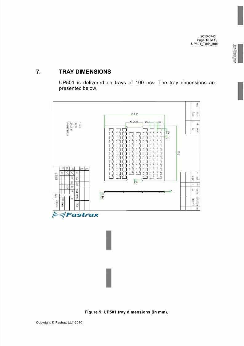
TRAY DIMENSIONS ..................................................................................... 18
7/28/2019 GPS_modem.pdf
http://slidepdf.com/reader/full/gpsmodempdf 5/19
2010-07-01Page 5 of 19
UP501_Tech_doc
Copyright © Fastrax Ltd. 2010
COMPLEMENTARY READING
The following Fastrax reference documents are complementaryreading for this document.
Ref. # Document name
1 Fastrax UP500 GPS Receiver – TechnicalDescription
2 NMEA Manual for Fastrax IT500 Series GPS
receivers

7/28/2019 GPS_modem.pdf
http://slidepdf.com/reader/full/gpsmodempdf 6/19
2010-07-01Page 6 of 19
UP501_Tech_doc
Copyright © Fastrax Ltd. 2010
1. GENERAL DESCRIPTION
The Fastrax UP501 is a GPS receiver module with embeddedantenna and tiny form factor 22.0 x 22.0mm x 8mm. The size,mechanics and interface connectivity is an exact match with theFastrax UP500 [1]. Therefore, customers may replace UP500 withUP501 to gain improved performance with minimal design effort.
The Fastrax UP501 receiver provides very fast TTFF together with
market leading weak signal acquisition and tracking sensitivity figures.The Fastrax UP501 module supports enhanced navigation accuracyby utilizing WAAS/EGNOS corrections, which may be enabled viaNMEA command [2]. The Fastrax UP501 can also utilize 14-dayspredicted ephemeris data in AGPS applications.
The Fastrax UP501 module provides complete signal processing frominternal antenna to serial data output in NMEA messages. Themodule requires a power supply VDD and a backup supply VDD_Bvoltage for non-volatile RTC & RAM blocks. There is a variant of themodule available with on-board backup battery, which will eliminate
the need for external backup voltage source. PPS signal output isavailable for accurate timing applications.
The Fastrax UP501 module interfaces to the customer’s applicationvia one serial port, which uses CMOS voltage levels. If RS232 signallevels are required, there is a variant of Fastrax UP501 available withon-board CMOS-to-RS232 level converter. UP501U is communicatingvia USB port and has VDD range up to 5.5V. PPS output is availablefrom the module as CMOS level signal.
There is also a Dual-SAW filter version of the UP501 available. This
module variant is named as Fastrax UP501D. The Dual-SAW filter istargeted for telematic applications where a radio transmitter is placedclose to the GPS receiver. The dual filter design will provide higher attenuation outside of the GPS band and it helps to reduce the risk of EMC issues that are sometimes present when high-gain systems(GPS receiver) that are in strong signal field (radio transmitter).
For complete electrical compatibility with UP500, there is a high-voltage variant UP501H with 5.5V tolerant VDD supply.

7/28/2019 GPS_modem.pdf
http://slidepdf.com/reader/full/gpsmodempdf 7/19
2010-07-01Page 7 of 19
UP501_Tech_doc
Copyright © Fastrax Ltd. 2010
1.1 Default firmware configuration
Fastrax UP501 default firmware configuration:
1. Port 0: NMEA 9600 baud
2. NMEA output: GGA, RMC, GSV, GSA (all 1 sec interval)
3. DGPS/SBAS: Disabled (Module supports WAAS/EGNOS)
4. Datum: WGS84
1.2 UP500 vs. UP501
The table below will identify the differences between UP500 andUP501. This information is useful for customers who already haveproducts with UP500 and would like to upgrade to UP501.
Table 1. UP500 vs. UP501.
Item UP500 UP501 Note
VDD Range +3.0V…+5.5V +3.0V…+4.2V UP501H is up to +5.5V
SBAS default status Enabled Disabled Enable/disable withNMEA command.
Max. fix rate 5Hz 10Hz Configurable via NMEA.
Navigationsensitivity
-158dBm -165dBm
Cold start sensitivity -146dBm -148dBm
Power consumption [email protected] [email protected] Typical in navigation.
AGPS NA 14-dayspredictedephemeris.

7/28/2019 GPS_modem.pdf
http://slidepdf.com/reader/full/gpsmodempdf 8/19
7/28/2019 GPS_modem.pdf
http://slidepdf.com/reader/full/gpsmodempdf 9/19
2010-07-01Page 9 of 19
UP501_Tech_doc
Copyright © Fastrax Ltd. 2010
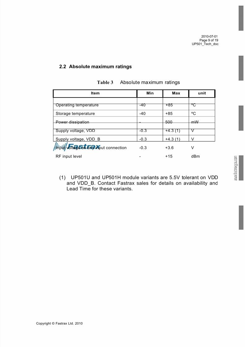
2.2 Absolute maximum ratings
Table 3 Absolute maximum ratings
Item Min Max unit
Operating temperature -40 +85 ºC
Storage temperature -40 +85 ºC
Power dissipation - 500 mW
Supply voltage, VDD -0.3 +4.3 (1) V
Supply voltage, VDD_B -0.3 +4.3 (1) V
Input voltage on any input connection -0.3 +3.6 V
RF input level - +15 dBm
(1) UP501U and UP501H module variants are 5.5V tolerant on VDD
and VDD_B. Contact Fastrax sales for details on availability andLead Time for these variants.
7/28/2019 GPS_modem.pdf
http://slidepdf.com/reader/full/gpsmodempdf 10/19
2010-07-01Page 10 of 19
UP501_Tech_doc
Copyright © Fastrax Ltd. 2010
3. OPERATION
3.1 Operating modes
After power up the receiver boots from the internal flash memory for normal operation. Modes of operation:
Tracking/navigating mode
Low power tracking/navigating mode
Backup mode
3.1.1 Tracking/Navigating mode
In tracking/navigating mode the Fastrax UP501 receiver module willsearch for additional satellites and collects almanac data. Once thereceiver has collected almanac data (this takes about 12 minutes from
Cold Start), it will enter Low Power Tracking mode. The VDD power consumption in table 1 is measured in Low Power Tracking/Navigating mode.
3.1.2 Low Power Tracking/Navigating mode
In Low power tracking/navigating mode the receiver continues normalnavigation but does not collect further Almanacs data. Therefore thecurrent consumption is reduced to level of <75 mW (<85 mW for UP501R with default UART baud rate).
3.1.3 Backup mode
When the operating voltage VDD is removed from the Fastrax UP501,the module enters Backup mode. In this mode, the module is keepingtime by the RTC oscillator. Also, satellite ephemeris data is stored inbattery backup RAM in order to get fast TTFF when VDD is connectedagain. Any user configuration settings are also valid as long as thebackup supply VDD_B is active. When the VDD_B is powered off, theconfiguration is reset to factory configuration on next power up.
7/28/2019 GPS_modem.pdf
http://slidepdf.com/reader/full/gpsmodempdf 11/19
2010-07-01Page 11 of 19
UP501_Tech_doc
Copyright © Fastrax Ltd. 2010
4. CONNECTIVITY
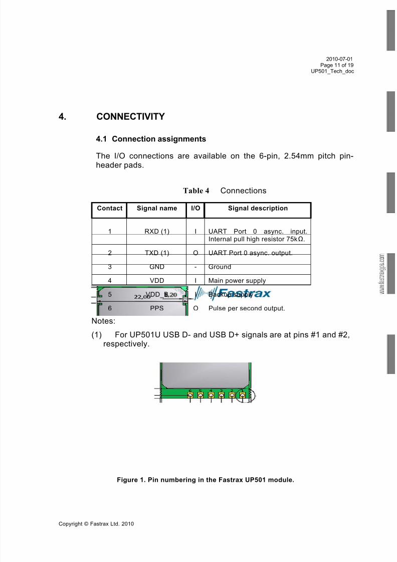
4.1 Connection assignments
The I/O connections are available on the 6-pin, 2.54mm pitch pin-header pads.
Table 4 Connections
Contact Signal name I/O Signal description
1 RXD (1) I UART Port 0 async. input.Internal pull high resistor 75kΩ.
2 TXD (1) O UART Port 0 async. output.
3 GND - Ground
4 VDD I Main power supply
5 VDD_B I Backup supply
6 PPS O Pulse per second output.
Notes:
(1) For UP501U USB D- and USB D+ signals are at pins #1 and #2,respectively.
Figure 1. Pin numbering in the Fastrax UP501 module.
7/28/2019 GPS_modem.pdf
http://slidepdf.com/reader/full/gpsmodempdf 12/19
2010-07-01Page 12 of 19
UP501_Tech_doc
Copyright © Fastrax Ltd. 2010
4.2 Power supply
The Fastrax UP501 module requires two separate power supplies:VDD_B for non-volatile back up block and the VDD for digital partsand I/O. VDD can be switched off when navigation is not needed but if possible keep the backup supply VDD_B active all the time in order tokeep the non-volatile RTC & RAM active for fastest possible TTFF.
Backup supply VDD_B draws typically 5 uA current in back up state.During navigation (while VDD is active) VDD_B current may peak up
to 100 uA, while staying at <30 uA average level.
On-board backup battery is available as an assembly option(UP501B). In this case the backup supply (VDD_B) should be leftopen and the module handles the backup state power supplyautomatically. The backup battery is charged when VDD supply isconnected. A fully charged internal back-up battery is able to keep theUP501B in back-up state for 4hours (typical at room temperature).
Main power supply VDD current varies according to the processor load and satellite acquisition. Typically VDD peak current is up to
40mA during Search mode. In Low Power Tracking mode the averageVDD current is typically below 25 mA for the Fastrax UP501 andUP501B modules, and below 28 mA for Fastrax UP501R module withdefault baud rate of 9600 baud.
4.3 Reset
Reset can be initiated by switching off VDD supply for >150 ms.
4.4 UART
The device supports UART communication via Port 0 of the GPS IC.With the standard firmware the Port 0 is configured by default toNMEA protocol (9600 baud).
I/O levels at the serial ports are CMOS compatible (see table 1). On-board RS232 level converter is available with the Fastrax UP501Rmodule.
4.5 PPS
The pulse-per-second (PPS) output provides an output for timingpurposes. There is a 100ms pulse once per second synchronized to
7/28/2019 GPS_modem.pdf
http://slidepdf.com/reader/full/gpsmodempdf 13/19
2010-07-01Page 13 of 19
UP501_Tech_doc
Copyright © Fastrax Ltd. 2010
UTC second at rising edge when the receiver has a valid 3D positionfix available.
4.6 Mechanical dimensions and contact numbering
Module size is 22.0 mm (width) x 22.0 mm (length) x 8 mm
(thickness). General tolerance is 0.3 mm. Detailed mechanicaldrawing is presented in figure 2. Mechanically the UP501 is fullycompatible with the UP500 module.

7/28/2019 GPS_modem.pdf
http://slidepdf.com/reader/full/gpsmodempdf 14/19
2010-07-01Page 14 of 19
UP501_Tech_doc
Copyright © Fastrax Ltd. 2010
Figure 2. Mechanics drawing of the Fastrax UP501 module.
7/28/2019 GPS_modem.pdf
http://slidepdf.com/reader/full/gpsmodempdf 15/19
2010-07-01Page 15 of 19
UP501_Tech_doc
Copyright © Fastrax Ltd. 2010
5. MODULE OPTIONS
The Fastrax UP501 module is available in three different HW-configurations. This makes it possible for a customer to select optimalsolution for different applications depending on required functionalityand/or price target.
The following table will summarize the differences in the FastraxUP501 module options.
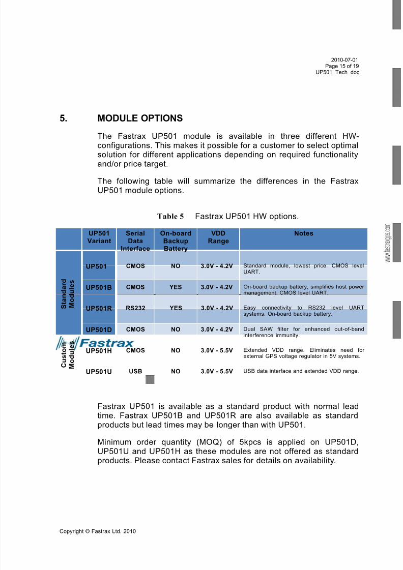
Table 5 Fastrax UP501 HW options.
UP501Variant
SerialData
Interface
On-boardBackupBattery
VDDRange
Notes
S t a n d a r d
M o d u l e s
UP501 CMOS NO 3.0V - 4.2V Standard module, lowest price. CMOS levelUART.
UP501B CMOS YES 3.0V - 4.2V On-board backup battery, simplifies host power management. CMOS level UART.
UP501R RS232 YES 3.0V - 4.2V Easy connectivity to RS232 level UARTsystems. On-board backup battery.
C u s t o m
M o d u l e s
UP501D CMOS NO 3.0V - 4.2V Dual SAW filter for enhanced out-of-bandinterference immunity.
UP501H CMOS NO 3.0V - 5.5V Extended VDD range. Eliminates need for external GPS voltage regulator in 5V systems.
UP501U USB NO 3.0V - 5.5V USB data interface and extended VDD range.
Fastrax UP501 is available as a standard product with normal leadtime. Fastrax UP501B and UP501R are also available as standardproducts but lead times may be longer than with UP501.
Minimum order quantity (MOQ) of 5kpcs is applied on UP501D,UP501U and UP501H as these modules are not offered as standardproducts. Please contact Fastrax sales for details on availability.
7/28/2019 GPS_modem.pdf
http://slidepdf.com/reader/full/gpsmodempdf 16/19
2010-07-01Page 16 of 19
UP501_Tech_doc
Copyright © Fastrax Ltd. 2010
6. PCB MOUNTING
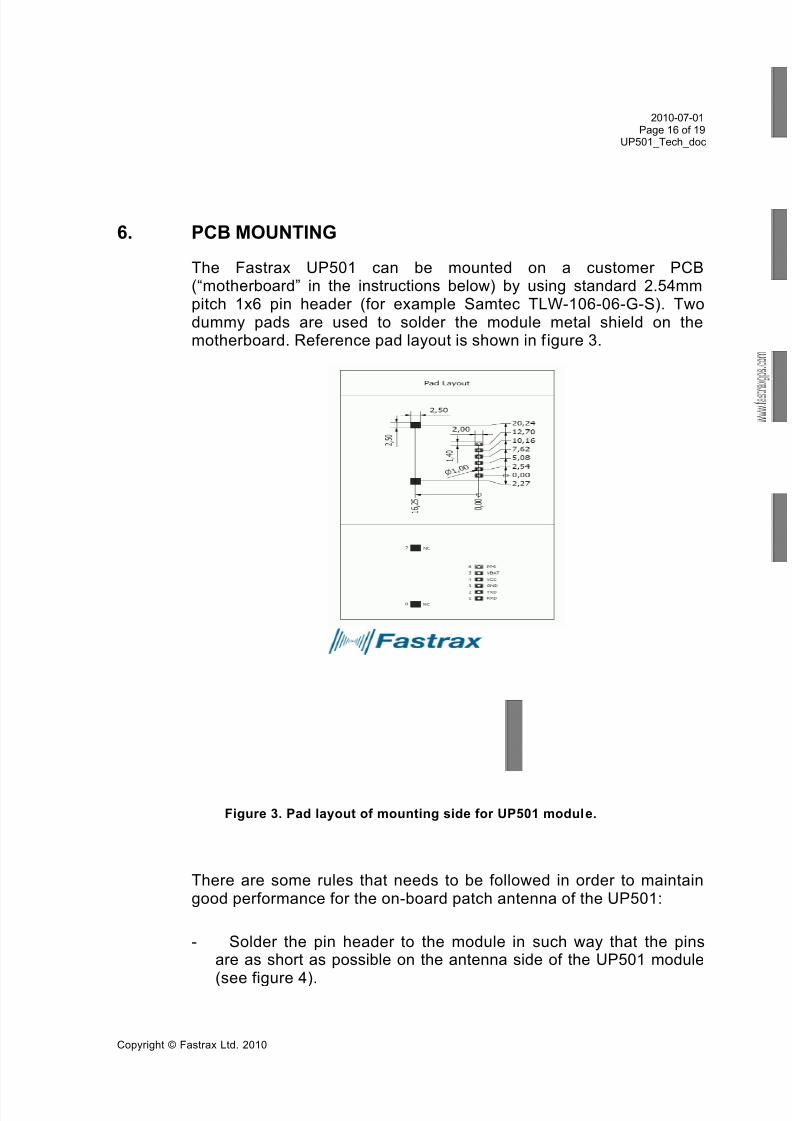
The Fastrax UP501 can be mounted on a customer PCB(“mother board” in the instructions below) by using standard 2.54mmpitch 1x6 pin header (for example Samtec TLW-106-06-G-S). Twodummy pads are used to solder the module metal shield on themotherboard. Reference pad layout is shown in f igure 3.
Figure 3. Pad layout of mounting side for UP501 module.
There are some rules that needs to be followed in order to maintaingood performance for the on-board patch antenna of the UP501:
- Solder the pin header to the module in such way that the pinsare as short as possible on the antenna side of the UP501 module
(see figure 4).
7/28/2019 GPS_modem.pdf
http://slidepdf.com/reader/full/gpsmodempdf 17/19
2010-07-01Page 17 of 19
UP501_Tech_doc
Copyright © Fastrax Ltd. 2010
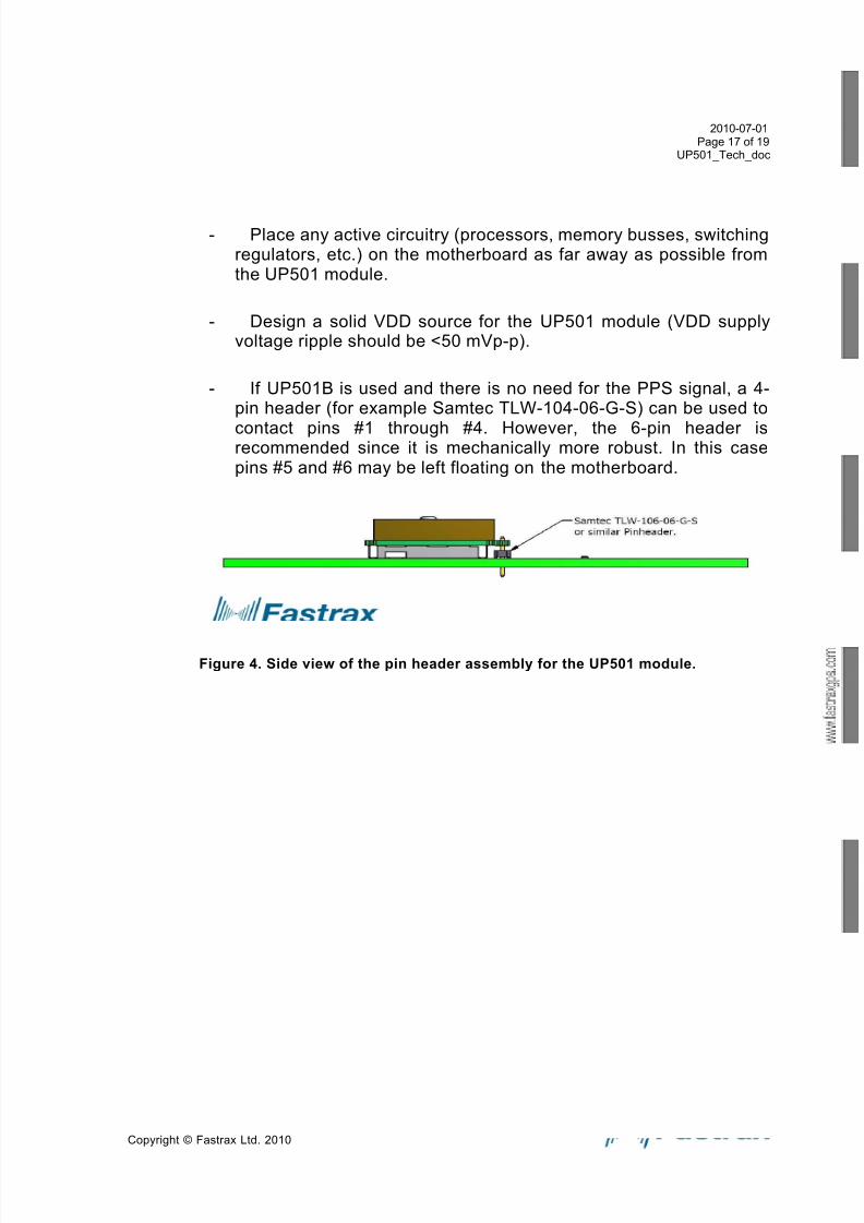
- Place any active circuitry (processors, memory busses, switchingregulators, etc.) on the motherboard as far away as possible fromthe UP501 module.
- Design a solid VDD source for the UP501 module (VDD supplyvoltage ripple should be <50 mVp-p).
- If UP501B is used and there is no need for the PPS signal, a 4-pin header (for example Samtec TLW-104-06-G-S) can be used to
contact pins #1 through #4. However, the 6-pin header isrecommended since it is mechanically more robust. In this casepins #5 and #6 may be left floating on the motherboard.
Figure 4. Side view of the pin header assembly for the UP501 module.
7/28/2019 GPS_modem.pdf
http://slidepdf.com/reader/full/gpsmodempdf 18/19

7/28/2019 GPS_modem.pdf
http://slidepdf.com/reader/full/gpsmodempdf 19/19
2010-07-01Page 19 of 19
UP501_Tech_doc
Copyright © Fastrax Ltd 2010
Contact Information
Fastrax Ltd.
Street Address: Valimotie 7, 01510 Vantaa, FINLAND
Tel: +358 (0)424 733 1
Fax: +358 (0)9 8240 9691
http://www.fastraxgps.com
E-mail:
Sales: [email protected]
Support: [email protected]


