GPR-3100 Oxygen Purity Analyzer - Process Sensing
47
2855 Metropolitan Place, Pomona, CA 91767 USA ♦ Tel: 909-392-6900, Fax: 909-392-3665, www.aii1.com, e-mail: [email protected] Rev 10/15 Advanced Sensor Technology Unmatched ROI and Performance in O2 Analysis 24 Month Life Continuous Exposure @ 100% O2 Sensitivity < 0.1% Oxygen Temperature Control Sample System 3 Suppressed Ranges, 0-100% FS Range 4½ Digit Display with 0.01% Resolution Insensitive to Vibration and Moisture 2 Field Selectable Alarm Setpoints Auto Ranging or Single Fixed Options: Auto-Zero and Auto-Cal Remote Communication via USB, RS232, RS485 GPR-3100 Oxygen Purity Analyzer Innovative Sensor & Analyzer (see back page) Technical Specifications * Accuracy: < 2% of FS range under constant conditions, e.g. constant temperature, flow rate and ambient pressure: +5% with temperature fluctuation of +10°F Analysis: Suppressed ranges: 90-100%, 80-100%, 50-100% and 0-100% FS range; Auto-ranging or fixed single range Application: Continuous analysis of high purity oxygen concentrations up to 100% oxygen in inert, He, H2 and mixed gases Approvals: CE Area Classification: General purpose Alarms: Two adjustable form C relay contacts non-latching; “weak sensor” indicator; power failure; system failure Calibration: Max interval—3 months. Use certified span gas with 97- 100% O2 (balance N2). To comply with FDA require- ments for medical grade O2, zero calibrate with not less than 99.9% N2 (balance O2) or span calibrate with not less than 99.99% O2 (balance N2). For Oxygen 93 (transfilling), calibrate with 93% +0.1% O2 (balance N2). Compensation: Barometric pressure and temperature; temperature con- trolled sample system and sensor for stability Connections: Compression tube fittings 1/4" inlet, 1/4” vent Controls: Water resistant keypad; menu driven range selection, calibration, alarm and system functions Data Acquisition: Selectable data point intervals Display: Graphical LCD 5” x 2.75”; resolution .01%; displays real time ambient temperature and pressure Enclosure: Painted aluminum 7.5” x 10.8” x 12.25” panel mount Flow: Not flow sensitive; recommended flow rate 2 SCFH Linearity: > .995 over all ranges Pressure: Inlet - regulate to 5-30 psig to deliver 2 SCFH flow; vent - atmospheric Power: Universal; specify 110 or 220 VAC for heater system Range ID: 1-5V; Optional (1) 4-20mA non-isolated OR (2) relay contacts w/ 4-20mA or 1-5V Response Time: 90% of final FS reading < 13 seconds Sample System: Stainless steel wetted parts, flow control, flow indicator, special integral sample Sensitivity: < 0.1% oxygen Sensor Model: GPR-11-120-OP Sensor Life: 24 months in 100% oxygen at 25ºC and 1 atm Signal Output: 4-20mA isolated, 0-1V, and 0-5V Temp. Range: 5ºC to 45ºC Warranty: 12 months analyzer; 12 months sensor Optional Equipment 19” rack, wall mounting, auto zero/cal, remote communication-contact factory * Specification subject to change without notice. ISO 9001:2008 Certified INTERTEK Certificate No. 485
Transcript of GPR-3100 Oxygen Purity Analyzer - Process Sensing

2855 Metropolitan Place, Pomona, CA 91767 USA ♦ Tel: 909-392-6900, Fax: 909-392-3665, www.aii1.com, e-mail: [email protected] Rev 10/15
Advanced Sensor Technology Unmatched ROI and Performance in O2 Analysis
24 Month Life Continuous Exposure @ 100% O2
Sensitivity < 0.1% Oxygen
Temperature Control Sample System
3 Suppressed Ranges, 0-100% FS Range
4½ Digit Display with 0.01% Resolution
Insensitive to Vibration and Moisture
2 Field Selectable Alarm Setpoints
Auto Ranging or Single Fixed
Options: Auto-Zero and Auto-Cal
Remote Communication via USB, RS232, RS485
GPR-3100 Oxygen Purity Analyzer
Innovative Sensor & Analyzer (see back page)
Technical Specifications *
Accuracy: < 2% of FS range under constant conditions, e.g. constant temperature, flow rate and ambient pressure: +5% with temperature fluctuation of +10°F
Analysis: Suppressed ranges: 90-100%, 80-100%, 50-100% and 0-100% FS range; Auto-ranging or fixed single range
Application: Continuous analysis of high purity oxygen concentrations up to 100% oxygen in inert, He, H2 and mixed gases
Approvals: CE
Area Classification: General purpose
Alarms: Two adjustable form C relay contacts non-latching; “weak sensor” indicator; power failure; system failure
Calibration:
Max interval—3 months. Use certified span gas with 97-100% O2 (balance N2). To comply with FDA require-ments for medical grade O2, zero calibrate with not less than 99.9% N2 (balance O2) or span calibrate with not less than 99.99% O2 (balance N2). For Oxygen 93 (transfilling), calibrate with 93% +0.1% O2 (balance N2).
Compensation: Barometric pressure and temperature; temperature con-trolled sample system and sensor for stability
Connections: Compression tube fittings 1/4" inlet, 1/4” vent
Controls: Water resistant keypad; menu driven range selection, calibration, alarm and system functions
Data Acquisition: Selectable data point intervals
Display: Graphical LCD 5” x 2.75”; resolution .01%; displays real time ambient temperature and pressure
Enclosure: Painted aluminum 7.5” x 10.8” x 12.25” panel mount
Flow: Not flow sensitive; recommended flow rate 2 SCFH
Linearity: > .995 over all ranges
Pressure:
Inlet - regulate to 5-30 psig to deliver 2 SCFH flow; vent - atmospheric
Power: Universal; specify 110 or 220 VAC for heater system
Range ID: 1-5V; Optional (1) 4-20mA non-isolated OR (2) relay contacts w/ 4-20mA or 1-5V
Response Time: 90% of final FS reading < 13 seconds
Sample System: Stainless steel wetted parts, flow control, flow indicator, special integral sample
Sensitivity: < 0.1% oxygen
Sensor Model: GPR-11-120-OP
Sensor Life: 24 months in 100% oxygen at 25ºC and 1 atm
Signal Output: 4-20mA isolated, 0-1V, and 0-5V
Temp. Range: 5ºC to 45ºC
Warranty: 12 months analyzer; 12 months sensor
Optional Equipment
19” rack, wall mounting, auto zero/cal, remote communication-contact factory
* Specification subject to change without notice.
ISO 9001:2008 Certified INTERTEK Certificate No. 485

2855 Metropolitan Place, Pomona, CA 91767 USA ♦ Tel: 909-392-6900, Fax: 909-392-3665, www.aii1.com, e-mail: [email protected] Rev 10/15
Advancements: Innovative design, materials Extend life in continuous use @ 100% O2 Control reaction rate @ 100% O2 Suppressed range capability Insensitive to vibration Compact inexpensive design
Performance: 24 month life @ 100% O2 Accuracy < + 2% FS Sensitivity 0.1% oxygen Capable of analysis > 99.50% Fast 13 response time Extended calibration period
Galvanic Oxygen Purity Sensor
GPR-3100 W
Background Oxygen Purity Analyzers Historically, the production of pure oxygen has been confined to medical grade oxygen (99.0%). However, the demand for oxygen is expanding rapidly due to developments in chemical processes requiring elevated levels of oxygen (85-95%) that boost yields and re-duce emissions without significant cost increases. Analyzers based on paramagnetic sensors have been the primary method of measuring oxygen purity. Accu-racy at the suppressed range of 98-100% oxygen is their strength. However, compensating for their weak-
nesses is very expensive as they are sensitive to changes in the flow rate of the sample gas, the pres-ence of minute particulates and moisture, temperature variations and vibration and require frequent calibra-tion. Analyzers based on galvanic oxygen sensors have al-ways generated interest for oxygen purity measure-ments because they are specific to oxygen, versatile, low maintenance and less expensive. However, short sensor life and drift in the sensor’s signal output with time have precluded their use.
Major Advancement in Galvanic Sensor Technology An new galvanic sensor has been developed that is capable of precisely ana-lyzing 100% oxygen concentrations continuously over a two (2) year period. This proprietary design addresses the challenges of: 1) providing a sufficient amount of anode material to support the reduction of oxygen over several years, 2) maintaining at all times a sufficient concentration of hydroxyl ions to support the reduction of oxygen at and near the sensing electrode, and, 3) preventing the build-up of PbO at and near the sensing electrode that can cause the signal output of the sensor to drop or drift with time. Through proprietary means the production rate of the reaction product is con-trolled without sacrificing either the fast response time (less than 13 seconds) or any of the features (described above) of analyzers based on galvanic sen-sors. The performance of this proprietary sensor was confirmed over 14 months of testing and exhibited excellent stability in 100% oxygen. Test Results With the sensor and sample gas lines temperature controlled and the signal output of the sensor compensated for ambient pressure variations, it was pos-sible to measure oxygen in the suppressed range of 90-100% with less than +1% of full scale (+0.1% oxygen) accuracy. The calibration was checked peri-odically and found to be within +1% of full scale over the 14 month test peri-od suggesting the interval between calibrations could be extended to several months.
Conclusion The GPR-3100 galvanic sensor based Oxygen Purity Analyzer offers a very viable and cost effective solution for measuring elevated oxygen levels up to and above 99.5% in a maximum suppressed range of 90-100% with excellent accuracy and stability, a significant reduction in calibration requirements, unaf-fected by vibration and minor amounts of particulates and moisture.

Advanced Instruments Inc.
2855 Metropolitan Place, Pomona, CA 91767 USA ♦ Tel: 909-392-6900, Fax: 909-392-3665, e-mail: [email protected], www.aii2.com
Owner’s Manual
GPR-3100 Oxygen Purity Analyzer
Advanced Sensor Technology 24 Month Operating Life in 100% Oxygen Inherent Accuracy 0.1%, Resolution 00.01%
Auto Ranging & Suppressed Range Capability Temperature Controlled & Barometric Compensationsy

Advanced Instruments Inc.
Table of Contents
Introduction
1
Quality Control Certification
2
Safety
3
Features & Specifications
4
Operation
5
Maintenance
6
Spare Parts
7
Troubleshooting
8
Warranty
9
(MSDS) Material Safety Data Sheet
10
Reference Drawings
As Required
Rev 3/2004 i

Advanced Instruments Inc.
1 Introduction
Thank You For Your Business
Your new oxygen analyzer is a precision piece of equipment designed to give you years of use in variety of industrial oxygen applications.
This analyzer is designed to measure the purity of oxygen gas containing innert gases such as nitrogen, helium or argon and/or other reactive gases such as hydrogen and gaseous hydrocarbon gases as minor contaminants.
In order to derive maximum performance from your new oxygen analyzer, please read and follow the guidelines provided in this Owner’s Manual.
The serial number of this analyzer may be found on the inside the analyzer. You should note the serial number in the space provided and retains this Owner’s Manual as a permanent record of your purchase, for future reference and for warranty considerations.
Serial Number: _______________________
Every effort has been made to select the most reliable state of the art materials and components designed for superior performance and minimal cost of ownership. This analyzer was tested thoroughly by the manufacturer for best performance. However, modern electronic devices do require service from time to time. The warranty included herein plus a staff of trained professional technicians to quickly service your analyzer is your assurance that we stand behind every analyzer sold.
Advanced Instruments Inc. appreciates your business and pledge to make effort to maintain the highest possible quality standards with respect to product design, manufacturing and service.
1
Advanced Instruments Inc.
2 Quality Control Certification
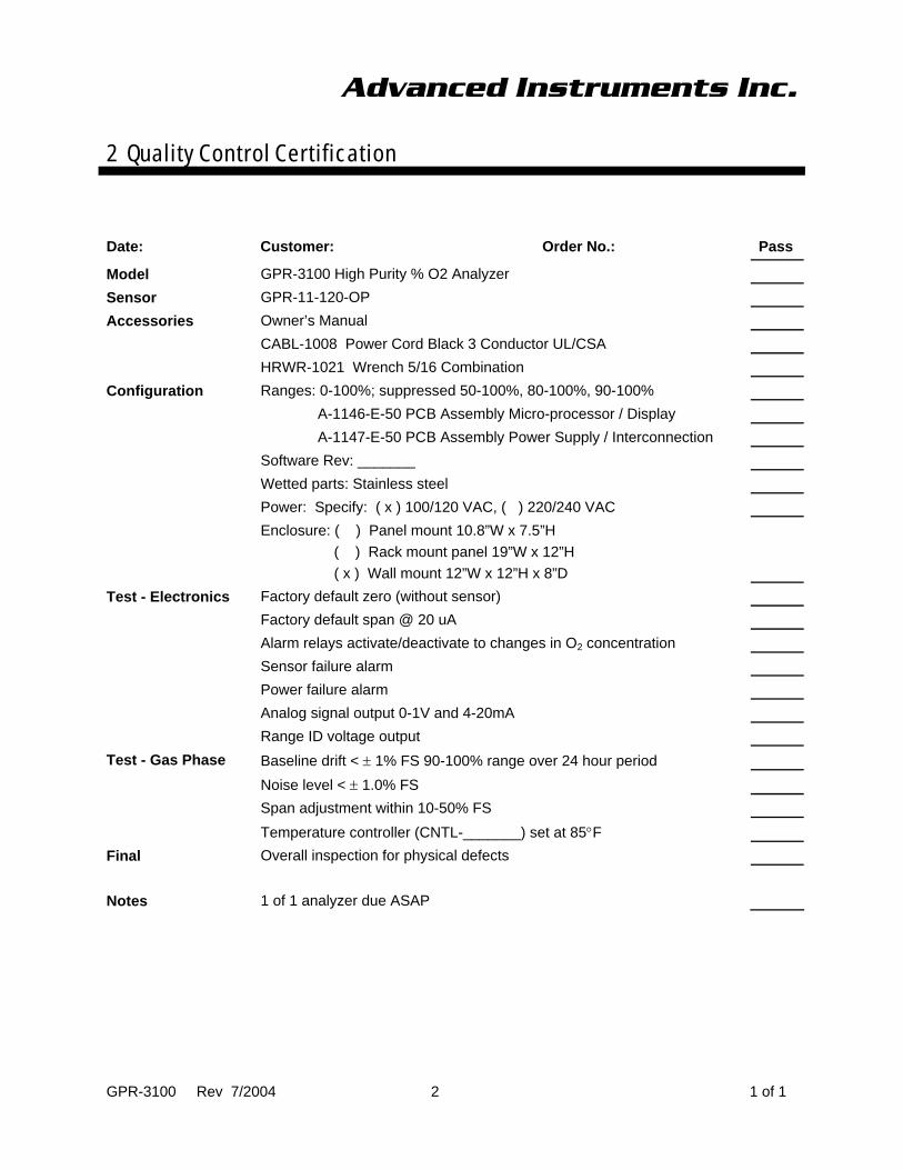
Date: Customer: Order No.: Pass
Model GPR-3100 High Purity % O2 Analyzer
Sensor GPR-11-120-OP
Accessories Owner’s Manual
CABL-1008 Power Cord Black 3 Conductor UL/CSA
HRWR-1021 Wrench 5/16 Combination
Configuration Ranges: 0-100%; suppressed 50-100%, 80-100%, 90-100%
A-1146-E-50 PCB Assembly Micro-processor / Display
A-1147-E-50 PCB Assembly Power Supply / Interconnection
Software Rev: _______
Wetted parts: Stainless steel
Power: Specify: ( x ) 100/120 VAC, ( ) 220/240 VAC
Enclosure: ( ) Panel mount 10.8”W x 7.5”H ( ) Rack mount panel 19”W x 12”H ( x ) Wall mount 12”W x 12”H x 8”D
Test - Electronics Factory default zero (without sensor)
Factory default span @ 20 uA
Alarm relays activate/deactivate to changes in O2 concentration
Sensor failure alarm
Power failure alarm
Analog signal output 0-1V and 4-20mA
Range ID voltage output
Test - Gas Phase Baseline drift < ± 1% FS 90-100% range over 24 hour period
Noise level < ± 1.0% FS
Span adjustment within 10-50% FS
Temperature controller (CNTL-_______) set at 85°F
Final Overall inspection for physical defects
Notes 1 of 1 analyzer due ASAP
GPR-3100 Rev 7/2004 2 1 of 1

Advanced Instruments Inc.
3 Safety
This section summarizes the essential generic precautions applicable to all analyzers. Additional precautions specific to individual analyzers are contained in the following sections of this manual. To operate the analyzer safely and obtain maximum performance follow the basic guidelines outlined in this Owner’s Manual.
Caution: This symbol is used throughout the Owner’s Manual to CAUTION and alert the user to recommended safety and/or operating guidelines.
Danger: This symbol is used throughout the Owner’s Manual to identify sources of immediate DANGER such as the presence of hazardous voltages.
Read Instructions: Before operating the analyzer read the instructions.
Retain Instructions: The safety precautions and operating instructions found in the Owner’s Manual should be retained for future reference.
Heed Warnings: Follow all warnings on the analyzer, accessories (if any) and in this Owner’s Manual.
Follow Instructions: Observe all precautions and operating instructions. Failure to do so may result in personal injury or damage to the analyzer.
Inlet Pressure: Recommended 5-30 psi, 100 psi maximum.
Outlet Pressure: The sample gas vent pressure should be atmospheric.
Oxygen Sensor: DO NOT open the sensor. The sensor contains a corrosive liquid electrolyte that could be harmful if touched or ingested, refer to the Material Safety Data Sheet contained in the Owner’s Manual appendix. Avoid contact with any liquid or crystal type powder in or around the sensor or sensor housing, as either could be a form of electrolyte. Leaking sensors should be disposed of in accordance with local regulations.
Mounting: The analyzer is approved for indoor use only. It may be used outdoors with optional enclosures. Mount as recommended by the manufacturer.
Power: Supply power to the analyzer only as rated by the specification in Section 4 nd/or markings on the analyzer enclosure. The wiring/cords that connect the analyzer to the power source should be installed in accordance with recognized electrical standards and so they are not pinched particularly near the power source and the point where they attach to the analyzer. Never yank a power cord to remove it from an outlet or from the analyzer.
Operating Temperature: The maximum operating temperature is 45º C.
Heat: Situate and store the analyzer away from sources of heat.
Liquid and Object Entry: The analyzer should not be immersed in any liquid. Care should be taken so that liquids are not spilled into and objects do not fall into the inside of the analyzer.
Handling: Do not use force when using the switches and knobs. Before moving your analyzer be sure to disconnect the wiring/power cord and any cables connected to the output terminals located on the analyzer.
Rev 10/2002 3 1

Advanced Instruments Inc.
3 Safety
Serviceability: Except for replacing the oxygen sensor, there are no parts inside the analyzer for the operator to service.
Only trained personnel with the authorization of their supervisor should conduct maintenance.
Oxygen Sensor: DO NOT open the sensor. The sensor contains a corrosive liquid electrolyte that could be harmful if touched or ingested, refer to the Material Safety Data Sheet contained in the Owner’s Manual appendix. Avoid contact with any liquid or crystal type powder in or around the sensor or sensor housing, as either could be a form of electrolyte. Leaking sensors should be disposed of in accordance with local regulations.
Troubleshooting: Consult the guidelines in Section 8 for advice on the common operating errors before concluding that your analyzer is faulty.
Do not attempt to service the analyzer beyond those means described in this Owner’s Manual. Do not attempt to make repairs by yourself as this will void the warranty as per Section 9 and may result in electrical shock, injury or damage. All other servicing should be referred to qualified service personnel.
Cleaning: The analyzer should be cleaned only as recommended by the manufacturer. Wipe off dust and dirt from the outside of the unit with a soft damp cloth then dry immediately. Do not use solvents or chemicals.
Nonuse Periods: Isolate ppb and ppm oxygen sensors as described in this manual and disconnect the power when the analyzer is left unused for a long period of time.
Rev 10/2002 3 2

Technical Specifications
Accuracy: < 1% of FS range at constant conditions; inherent accu-racy of 0.1% following calibration with 95-100% oxygen
Analysis: 0-100% full scale range; 50-100%, 80-100%, 90-100 sup-pressed ranges
Application: Continuous monitoring of high purity oxygen levels up to 100% oxygen in inert, helium, hydrogen and mixed gases
Approvals: CE
Area Classification: General purpose
Alarms: 2 adjustable form C relay contacts non-latching; “weak sensor” indicator; power failure; system failure
Calibration:
Certified gas of O2 balance N2 approximating 95-100% oxygen for optimum accuracy; otherwise, O2 content should approximate 80% of full scale range
Compensation: Barometric pressure and temperature; temperature con-trolled heated sample system and sensor housing
Connections: Compression tube fittings 1/8” inlet; 1/4” vent
Controls: Water resistant keypad; menu driven range selection, calibration, alarm and system functions
Data Acquisition: Selectable data point intervals
Display: Graphical LCD 5 x 2.75; resolution .01%; displays real time ambient temperature and pressure
Enclosure: Painted aluminum 7.5” x 10.8” x 12.25” panel mount
Flow Sensitivity: None between 1-3 SCFH, 2 SCFH recommended
Linearity: > .995 over all ranges
Pressure: Inlet - regulate to 5-30 psig; vent - atmospheric
Power: Specify 100/120 or 220/240 VAC
Response Time: 90% of final FS reading < 13 seconds
Sample System: Flow control, flow indicator, special integral sample temperature equalization system
Sensitivity: 0.1% oxygen
Sensor Model: GPR-11-120-OP - requires no maintenance
Sensor Life: 24 months in 100% oxygen at 25ºC and 1 atm
Signal Output: 4-20mA isolated and 0-1V
Temp. Range: 5º to 45ºC
Warranty: 12 months analyzer; 12 months sensor
Wetted Parts: 316 stainless steel
Optional Equipment
Bezel for 19” rack mounting, wall mount NEMA4 and 4X enclosure
Sample conditioning accessories - contact factory
GPR-3100 Oxygen Purity Analyzer
Breakthrough Sensor Technology
24 month life at 100% Oxygen Levels
Accuracy < 1% FS Range
Sensitivity < 0.1% Oxygen
No maintenance
Inherent Accuracy 0.1% Following
Calibration With 100% Oxygen
4 Standard Analysis Ranges including
3 Suppressed Ranges 50/80/90-100%
Auto Zero, Span Calibration
Temperature Controlled Sample System
Pressure Compensated
Remote Communication Link
Certified ISO 9001 QA System
2855 Metropolitan Place, Pomona, CA 91767 USA ♦ Tel: 909-392-6900, Fax: 909-392-3665, www.aii1.com, e-mail: [email protected] Rev 5/05
Advanced Instruments Inc. Gas analysis solutions through advanced analyzer and sensor technology
‘the only electrochemical sensor based analyzer
capable of analyzing > 99.5% pure oxygen
continuously 24/7 for 24 months‘

Advanced Instruments Inc.
5 Operation
GPR-3100 Rev 2/05 1
Principle of Operation
The GPR-3100 oxygen analyzer incorporates an advanced galvanic fuel cell type sensor capable of measuring 100% oxygen on a suppressed range of 90-100% on a continuous basis It is the only electrochemical sensor based analyzer capable of this measurement.
Background
The production of pure oxygen has been confined to the production of medical grade oxygen (99.0%, typically specified at 99.5% or greater purity). However, the demand for oxygen is expanding rapidly due largely to recent developments in chemical processes requiring elevated concentrations of oxygen (85-95%) that boost yields and reduce emissions without significant cost increases and to a lesser extent the growth of transfilling oxygen (92%) cylinders for home care use. The oxygen supplied can be be generated cryogenically or by pressure (PSA) or vacuum (VSA) swing adsorption methods.
Historically producers and users have relied on analyzers based on paramagnetic method for measuring oxygen purity. These sensor offer highly accurate results especially at the suppressed ranges of 90-100% oxygen. However, they are very sensitive to changes in the flow rate of sample gas, the presence of minute particulates and moisture, temperature variations and vibration. Consequently, paramagnetic analyzers are expensive and require frequent almost daily calibration.
Analyzers based on galvanic sensor concept have always generated an interest for oxygen purity measurements because they are specific to oxygen, versatile, low maintenance and inexpensive. However, short sensor life (3-4 months at best) and the gradual drop (drift) in the signal output of the micro-fuel cell with time has precluded their use.
Major Advancement in Galvanic Fuel Cell Sensor Technology
In competing with paramagnetic devices the focus was primarily on advancing the galvanic sensor technology but also included temperature controlling the sample gas and automatically compensating the signal output of the sensor for barometric pressure variations to assure a stable ‘drift free’ oxygen measurement.
An advanced galvanic sensor has been developed that provides two years of sensor life and is capable of operating properly on a continuous basis in 100% oxygen concentrations. This proprietary design addresses the challenges of:
Providing a sufficient amount of anode material to support the reduction of oxygen over several years.
Maintaining at all times a sufficient concentration of hydroxyl ions to support the reduction of oxygen at and near the sensing cathode.
Preventing the build-up of PbO at and near the sensing cathode (that eventually starts precipitating and covers the sensing cathode) that can cause the signal output of the sensor to drop (drift) with time.
Through proprietary means the production rate of the reaction product is controlled without sacrificing either the fast less than 13 second response time or any of the features (described above) of the micro-fuel cell analyzer. The resulting on-line and portable analyzers are approximately half the cost of their paramagnetic counterparts.
The performance of the sensor was validated over 14 months of testing and exhibited excellent stability in 100% oxygen. The sample flow rate was set at 0.1 lpm (and insensitive to changes of up to 1.0 lpm) with the sample vented to the atmosphere via ¼” diameter tube to minimize the backpressure.
Advanced Instruments Inc.
5 Operation
GPR-3100 Rev 2/05 2
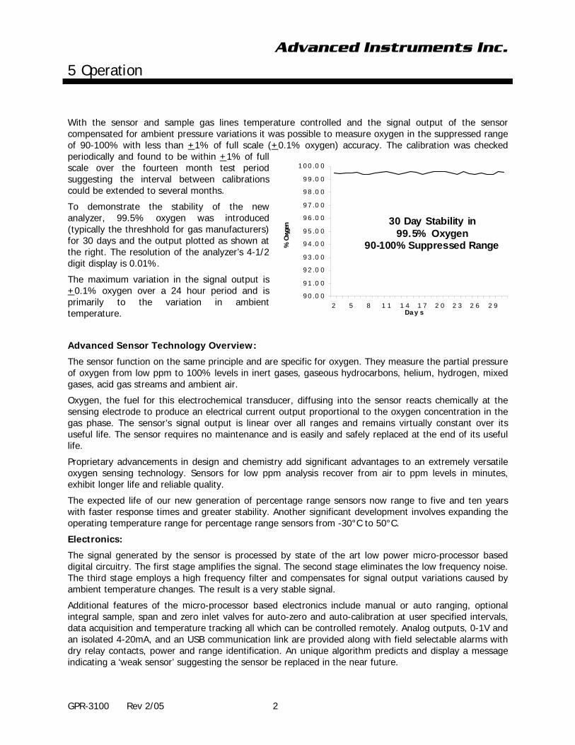
With the sensor and sample gas lines temperature controlled and the signal output of the sensor compensated for ambient pressure variations it was possible to measure oxygen in the suppressed range of 90-100% with less than +1% of full scale (+0.1% oxygen) accuracy. The calibration was checked periodically and found to be within +1% of full scale over the fourteen month test period suggesting the interval between calibrations could be extended to several months.
To demonstrate the stability of the new analyzer, 99.5% oxygen was introduced (typically the threshhold for gas manufacturers) for 30 days and the output plotted as shown at the right. The resolution of the analyzer’s 4-1/2 digit display is 0.01%.
The maximum variation in the signal output is +0.1% oxygen over a 24 hour period and is primarily to the variation in ambient temperature.
Advanced Sensor Technology Overview:
The sensor function on the same principle and are specific for oxygen. They measure the partial pressure of oxygen from low ppm to 100% levels in inert gases, gaseous hydrocarbons, helium, hydrogen, mixed gases, acid gas streams and ambient air.
Oxygen, the fuel for this electrochemical transducer, diffusing into the sensor reacts chemically at the sensing electrode to produce an electrical current output proportional to the oxygen concentration in the gas phase. The sensor’s signal output is linear over all ranges and remains virtually constant over its useful life. The sensor requires no maintenance and is easily and safely replaced at the end of its useful life.
Proprietary advancements in design and chemistry add significant advantages to an extremely versatile oxygen sensing technology. Sensors for low ppm analysis recover from air to ppm levels in minutes, exhibit longer life and reliable quality.
The expected life of our new generation of percentage range sensors now range to five and ten years with faster response times and greater stability. Another significant development involves expanding the operating temperature range for percentage range sensors from -30°C to 50°C.
Electronics:
The signal generated by the sensor is processed by state of the art low power micro-processor based digital circuitry. The first stage amplifies the signal. The second stage eliminates the low frequency noise. The third stage employs a high frequency filter and compensates for signal output variations caused by ambient temperature changes. The result is a very stable signal.
Additional features of the micro-processor based electronics include manual or auto ranging, optional integral sample, span and zero inlet valves for auto-zero and auto-calibration at user specified intervals, data acquisition and temperature tracking all which can be controlled remotely. Analog outputs, 0-1V and an isolated 4-20mA, and an USB communication link are provided along with field selectable alarms with dry relay contacts, power and range identification. An unique algorithm predicts and display a message indicating a ‘weak sensor’ suggesting the sensor be replaced in the near future.
9 0 .0 0
9 1 .0 0
9 2 .0 0
9 3 .0 0
9 4 .0 0
9 5 .0 0
9 6 .0 0
9 7 .0 0
9 8 .0 0
9 9 .0 0
1 0 0 .0 0
2 5 8 1 1 1 4 1 7 2 0 2 3 2 6 2 9
% O
xygen
Da y s
30 Day Stability in 99.5% Oxygen
90-100% Suppressed Range
Advanced Instruments Inc.
5 Operation
GPR-3100 Rev 2/05 3
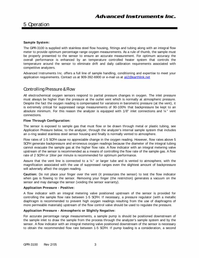
Sample System:
The GPR-3100 is supplied with stainless steel flow housing, fittings and tubing along with an integral flow meter to provide optimum percentage range oxygen measurements. As a rule of thumb, the sample must be properly presented to the sensor to ensure an accurate measurement. For optimum accuracy the overall performance is enhanced by an temperature controlled heater system that controls the temperature around the sensor to eliminate drift and daily calibration requirements associated with competitive analyzers.
Advanced Instruments Inc. offers a full line of sample handling, conditioning and expertise to meet your application requirements. Contact us at 909-392-6900 or e-mail us at [email protected]
Controlling Pressure & Flow
All electrochemical oxygen sensors respond to partial pressure changes in oxygen. The inlet pressure must always be higher than the pressure at the outlet vent which is normally at atmospheric pressure. Despite the fact the oxygen reading is compensated for variations in barometric pressure (at the vent), it is extremely critical for suppressed range measurements of 90-100% that backpressure be kept to an absolute minimum. For this reason the analyzer is equipped with 1/8” inlet connections and ¼” vent connections.
Flow Through Configuration:
The sensor is exposed to sample gas that must flow or be drawn through metal or plastic tubing, see Application Pressure below, to the analyzer, through the analyzer’s internal sample system that includes an o-ring sealed stainless steel sensor housing and finally is normally vented to atmosphere.
Flow rates of 1-5 SCFH cause no appreciable change in the oxygen reading. However, flow rates above 5 SCFH generate backpressure and erroneous oxygen readings because the diameter of the integral tubing cannot evacuate the sample gas at the higher flow rate. A flow indicator with an integral metering valve upstream of the sensor is recommended as a means of controlling the flow rate of the sample gas. A flow rate of 2 SCFH or 1liter per minute is recommended for optimum performance.
Assure that the vent line is connected to a ¼” or larger tube and is vented to atmosphere, with the magnification associated with the use of suppressed ranges even the slightest amount of backpressure will adversely affect the oxygen reading.
Caution: Do not place your finger over the vent (it pressurizes the sensor) to test the flow indicator when gas is flowing to the sensor. Removing your finger (the restriction) generates a vacuum on the sensor and may damage the sensor (voiding the sensor warranty).
Application Pressure - Positive:
A flow indicator with an integral metering valve positioned upstream of the sensor is provided for controlling the sample flow rate between 1-5 SCFH. If necessary, a pressure regulator (with a metallic diaphragm is recommended to prevent high oxygen readings resulting from the use of diaphragms of more permeable materials) upstream of the flow control valve should be used to regulate the pressure.
Application Pressure - Atmospheric or Slightly Negative:
For accurate percentage range measurements, a sample pump is should be positioned downstream of the sample inlet to draw the sample from the process through the analyzer’s sample system and by the sensor. A flow indicator with an integral metering valve positioned downstream of the sensor is necessary to obtain the recommended flow rate between 1-5 SCFH. If pump loading is a consideration, a second

Advanced Instruments Inc.
5 Operation
GPR-3100 Rev 2/05 4
throttle valve on the pump’s inlet side may be necessary to provide a bypass path so the sample flow rate is within the above parameters.
An eductor jet pump is an alternative to a pump that is used in classified areas since it has no moving parts or to eliminate the maintenance associated with mechanical pumps. The eductor must be positioned downstream of the sample outlet. The eductor has three (3) orifices and requires a source of compressed gas which enters through the top and exits at the bottom while drawing a mild vacuum (and sample gas) through the side orifice. A flow indicator with an integral metering valve positioned downstream of the sensor is recommended for controlling the sample flow rate between 1-5 SCFH.
To avoid erroneous oxygen readings and damaging the sensor:
Assure there are no restrictions in the sample line that could create and draw a vacuum exceeding 14” of water column on the sensor.
Avoid excessive flow rates above 5 SCFH which generate backpressure on the sensor.
Avoid sudden changes in pressure that can severely damage the sensor – assure a flow control valve is positioned upstream of the analyzer’s inlet.
Assure no particulates, liquids or condensation collect on the sensor that could block the diffusion of oxygen into the sensor.
Do not place your finger over the vent (it pressurizes the sensor) to test the flow indicator when gas is flowing to the sensor. Removing your finger (the restriction) generates a vacuum on the sensor and may damage the sensor (voiding the sensor warranty).
Advanced Instruments Inc.
5 Operation
GPR-3100 Rev 2/05 5
Calibration and Accuracy
Single Point Calibration: As previously described the galvanic oxygen sensor generates an electrical current sensor exhibiting an absolute zero, e.g. the sensor does not generate a current output in the absence of oxygen. Given these linearity and absolute zero properties, single point calibration is possible.
Pressure: Because sensors are sensitive to the partial pressure of oxygen in the sample gas their output is a function of the number of molecules of oxygen 'per unit volume'. Readouts in percent are permissible only when the total pressure of the sample gas being analyzed remains constant. The pressure of the sample gas and that of the calibration gas(es) must be the same (reality < 1-2 psi).
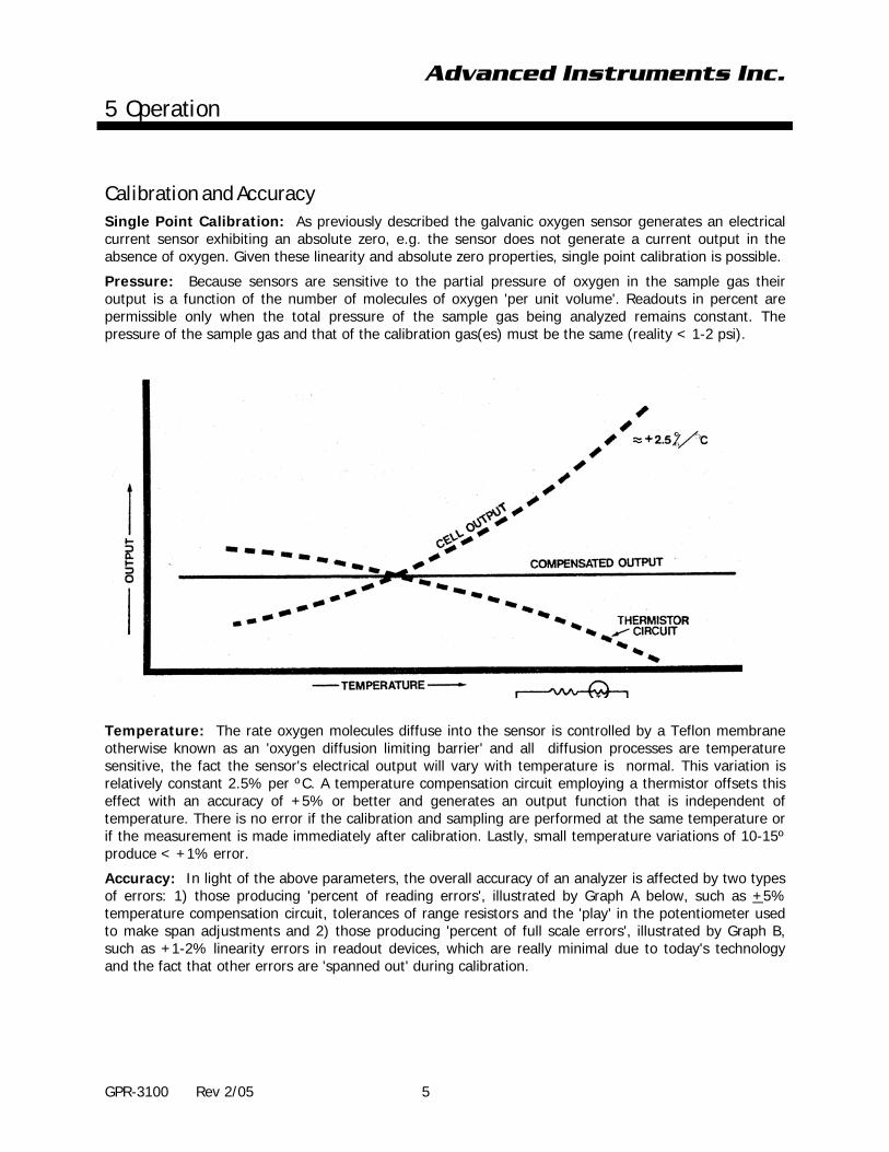
Temperature: The rate oxygen molecules diffuse into the sensor is controlled by a Teflon membrane otherwise known as an 'oxygen diffusion limiting barrier' and all diffusion processes are temperature sensitive, the fact the sensor's electrical output will vary with temperature is normal. This variation is relatively constant 2.5% per ºC. A temperature compensation circuit employing a thermistor offsets this effect with an accuracy of +5% or better and generates an output function that is independent of temperature. There is no error if the calibration and sampling are performed at the same temperature or if the measurement is made immediately after calibration. Lastly, small temperature variations of 10-15º produce < +1% error.
Accuracy: In light of the above parameters, the overall accuracy of an analyzer is affected by two types of errors: 1) those producing 'percent of reading errors', illustrated by Graph A below, such as +5% temperature compensation circuit, tolerances of range resistors and the 'play' in the potentiometer used to make span adjustments and 2) those producing 'percent of full scale errors', illustrated by Graph B, such as +1-2% linearity errors in readout devices, which are really minimal due to today's technology and the fact that other errors are 'spanned out' during calibration.

Advanced Instruments Inc.
5 Operation
GPR-3100 Rev 2/05 6
Graph C illustrates these 'worse case' specifications that are typically used to develop an analyzer's overall accuracy statement of +2% of full scale at constant temperature or +5% over the operating temperature range. QC testing is typically <+0.5% prior to shipment.
Example: As illustrated by Graph A any error, play in the multi-turn span pot or the temperature compensation circuit, during a span adjustment at 20.9% (air) of full scale range would be multiplied by a factor of 4.78 (100/20.9) if used for measurements of 95-100% oxygen concentrations. Conversely, an error during a span adjustment at 100% of full scale range is reduced proportionately for measurements of lower oxygen concentrations.
Recommendation: The analyzer may be calibrated by using a certified span gas of 80-90% value of the range of analysis. For example, for analysis on 90-100% range, use 98-99% oxygen as the span gas and for analysis on 80-90% oxygen, use 96-98% oxygen as the span gas.
Note: The accuracy of the analyzer is given as the % of full-scale. Therefore, the calibration of the analyzer must be done on the range of analysis or one range above the range of analysis. The analysis of the sample gas must be carried out on the range that provides the required accuracy.
Advanced Instruments Inc.
5 Operation
GPR-3100 Rev 2/05 7
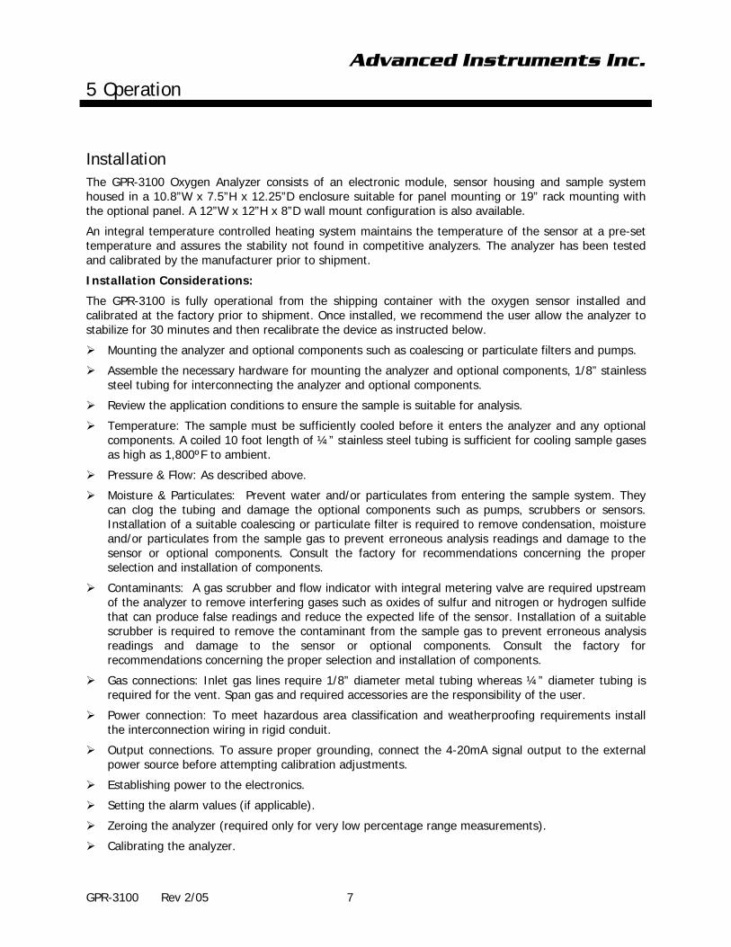
Installation
The GPR-3100 Oxygen Analyzer consists of an electronic module, sensor housing and sample system housed in a 10.8”W x 7.5”H x 12.25”D enclosure suitable for panel mounting or 19” rack mounting with the optional panel. A 12”W x 12”H x 8”D wall mount configuration is also available.
An integral temperature controlled heating system maintains the temperature of the sensor at a pre-set temperature and assures the stability not found in competitive analyzers. The analyzer has been tested and calibrated by the manufacturer prior to shipment.
Installation Considerations:
The GPR-3100 is fully operational from the shipping container with the oxygen sensor installed and calibrated at the factory prior to shipment. Once installed, we recommend the user allow the analyzer to stabilize for 30 minutes and then recalibrate the device as instructed below.
Mounting the analyzer and optional components such as coalescing or particulate filters and pumps.
Assemble the necessary hardware for mounting the analyzer and optional components, 1/8” stainless steel tubing for interconnecting the analyzer and optional components.
Review the application conditions to ensure the sample is suitable for analysis.
Temperature: The sample must be sufficiently cooled before it enters the analyzer and any optional components. A coiled 10 foot length of ¼” stainless steel tubing is sufficient for cooling sample gases as high as 1,800ºF to ambient.
Pressure & Flow: As described above.
Moisture & Particulates: Prevent water and/or particulates from entering the sample system. They can clog the tubing and damage the optional components such as pumps, scrubbers or sensors. Installation of a suitable coalescing or particulate filter is required to remove condensation, moisture and/or particulates from the sample gas to prevent erroneous analysis readings and damage to the sensor or optional components. Consult the factory for recommendations concerning the proper selection and installation of components.
Contaminants: A gas scrubber and flow indicator with integral metering valve are required upstream of the analyzer to remove interfering gases such as oxides of sulfur and nitrogen or hydrogen sulfide that can produce false readings and reduce the expected life of the sensor. Installation of a suitable scrubber is required to remove the contaminant from the sample gas to prevent erroneous analysis readings and damage to the sensor or optional components. Consult the factory for recommendations concerning the proper selection and installation of components.
Gas connections: Inlet gas lines require 1/8” diameter metal tubing whereas ¼” diameter tubing is required for the vent. Span gas and required accessories are the responsibility of the user.
Power connection: To meet hazardous area classification and weatherproofing requirements install the interconnection wiring in rigid conduit.
Output connections. To assure proper grounding, connect the 4-20mA signal output to the external power source before attempting calibration adjustments.
Establishing power to the electronics.
Setting the alarm values (if applicable).
Zeroing the analyzer (required only for very low percentage range measurements).
Calibrating the analyzer.
Advanced Instruments Inc.
5 Operation
GPR-3100 Rev 2/05 8
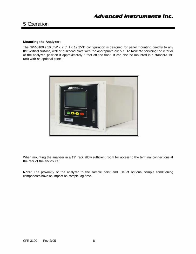
Mounting the Analyzer:
The GPR-3100’s 10.8”W x 7.5”H x 12.25”D configuration is designed for panel mounting directly to any flat vertical surface, wall or bulkhead plate with the appropriate cut out. To facilitate servicing the interior of the analyzer, position it approximately 5 feet off the floor. It can also be mounted in a standard 19” rack with an optional panel.
When mounting the analyzer in a 19” rack allow sufficient room for access to the terminal connections at the rear of the enclosure.
Note: The proximity of the analyzer to the sample point and use of optional sample conditioning components have an impact on sample lag time.
Advanced Instruments Inc.
5 Operation
GPR-3100 Rev 2/05 9
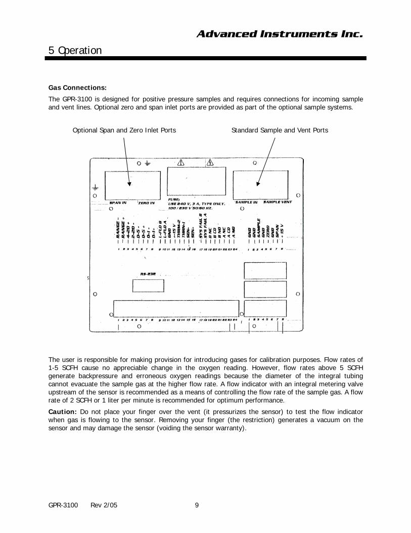
Gas Connections:
The GPR-3100 is designed for positive pressure samples and requires connections for incoming sample and vent lines. Optional zero and span inlet ports are provided as part of the optional sample systems.
Optional Span and Zero Inlet Ports Standard Sample and Vent Ports
The user is responsible for making provision for introducing gases for calibration purposes. Flow rates of 1-5 SCFH cause no appreciable change in the oxygen reading. However, flow rates above 5 SCFH generate backpressure and erroneous oxygen readings because the diameter of the integral tubing cannot evacuate the sample gas at the higher flow rate. A flow indicator with an integral metering valve upstream of the sensor is recommended as a means of controlling the flow rate of the sample gas. A flow rate of 2 SCFH or 1 liter per minute is recommended for optimum performance.
Caution: Do not place your finger over the vent (it pressurizes the sensor) to test the flow indicator when gas is flowing to the sensor. Removing your finger (the restriction) generates a vacuum on the sensor and may damage the sensor (voiding the sensor warranty).

Advanced Instruments Inc.
5 Operation
GPR-3100 Rev 2/05 10
Procedure:
Caution: Do not change the factory setting until instructed to do in this manual.
1. Regulate the pressure and flow of the incoming sample and zero/span calibration gas(es) as described in Controlling Pressure & Flow above.
2. Connect the ¼” vent line to the compression fitting labeled VENT.
3. Connect the 1/8” sample line to the fitting labeled SAMPLE.
4. Connect the 1/8” ZERO and SPAN gas lines as labeled, if equipped with optional sample system(s).
5. Once power is established to the analyzer, purge the air trapped inside the sample system.
6. Allow gas to flow through the analyzer for 3-5 minutes and set the flow rate to 2 SCFH
The analyzer is ready for calibration.
Power Connections:
Power for the on-line analyzers is supplied by an integral universal (100-240V AC) power supply. The appropriate AC line voltage is supplied with a standard power cord through a universal power entry module. A standard computer type power cord (P/N A-1008 is required for the universal power entry module.
Note: While the power entry module is universal, the heater is not. The heater must be configured to the local power supply (100-110 or 220-240V AC) at time of order.
Power Connections for External Calibration Valves

Advanced Instruments Inc.
5 Operation
GPR-3100 Rev 2/05 11
Output Connections
As illustrated above the sensor, alarm relays and signal output connections are hard wired to screw type terminal blocks located at the rear of the analyzer.
1. Use a small bladed screwdriver to loosen the appropriate terminal screws as illustrated above.
2. Strip the wires of the cable no more than 3/16 inch.
3. To connect to an active relay or “fail safe”, connect the live cable to the common terminal C and the secondary cable to the normally open NO terminal.
4. To break the connection upon relay activation, connect the secondary cable to the normally closed NC terminal.
5. Insert the stripped end of the cables into the appropriate terminal slots assuring no bare wire remains exposed that could come in contact with the back panel of the analyzer enclosure.
6. Tighten the terminal screws to secure the wires of the cable.
Danger: While connecting the cables to the relay terminals, ensure there is no voltage on the cables to prevent electric shock and possible damage to the analyzer.
Caution: Assure the stripped wire ends of the cable are fully inserted into the terminal slots and do not touch each other or the back panel of the analyzer enclosure.
Alarm Relays
The four alarm circuit connectors are spring loaded terminals for making connections to internal alarm relay contacts.
Alarm 1 and Alarm 2 - Represents two threshold type alarms that can be set and configured in the field from the analyzer’s display menu layout in Appendix A&B, Alarm menu as follows:
Establish independent set points
Either Hi or Lo
Either On or Off (enabled or disabled)
Both temporarily defeated using a user entered ‘timeout’ period (normally minutes)
The alarm set point represents a value. When the oxygen reading exceeds (high alarm) or falls below (low alarm) the alarm set point, the relay is activated and the LCD displays the alarm condition. When activated the alarms trigger SPDT Form C non-latching relays @ 5A, 30VDC or 240VAC resistive. To prevent chattering of the relays, a 2% hysteresis is added to the alarm set point. This means that the alarm will remain active until the oxygen reading has fallen 2% below the alarm set point (high alarm) or risen 2% above the alarm set point (low alarm) after the alarm was activated.
Aside from being totally defeated in the Off mode, the timeout feature is useful while replacing the oxygen sensor or during calibration when the oxygen reading might well rise above the alarm set point and trigger a false alarm.
Note: When making connections the user must decide whether to configure/connect Alarm 1 and Alarm 2 in failsafe mode (Normally Open – NO – where the alarm relay de-energizes and closes in an alarm condition) or non-failsafe mode (Normally Closed – NC – where alarm relay energizes and opens in an alarm condition).

Advanced Instruments Inc.
5 Operation
GPR-3100 Rev 2/05 12
Power Failure Alarm
A dry contact rated at 30VDC @ 1A is provided as a power failure alarm that activates when power supplied to the analyzer’s circuits is unacceptable. The contact is normally closed but opens when the power to the analyzer is switched off or interrupted and cannot be disabled.
Weak Sensor Indicator
A 5V output with negative ground is provided when the sensor is operational. The output is 0V when the sensor output drops 20-25% from a baseline established at a previous calibration.
4-20mA and 0-1V Signal Outputs
The analyzer provides 0-1V full scale with negative ground and a 4-20mA full scale fully isolated ground signals for external recording devices. The integral IC on the main PCB converts the 0-1V signal with negative ground to a 4-20mA fully isolated signal. A finer adjustment of the zero offset of the 4-20mA converter can be provided by a potentiometer mounted on the main PCB Assembly. Consult factory for instructions.
Caution: The integral 4-20mA converter is internally powered and does not require external power. DO NOT supply any voltage to either of the two terminals of the 4-20mA converter.
Range ID (identification)
A voltage output corresponding to each range is provided. The output of the highest range (normally CAL) is 5V and the remaining three ranges 4V, 3V and 2V for the low range.
RS-232 / USB Port
The digital signal output is a standard 9-pin D connection type RS-232 serial communications port used to connect the analyzer to a computer, terminal or other digital device.
Bi-directionsl data lines are provided via a RS-232C serial port for diagnostics and access via remote computer that enables the user to obtain status information and initiate functions remotely.

Advanced Instruments Inc.
5 Operation
GPR-3100 Rev 2/05 13
Installing the Oxygen Sensor
The GPR-3100 is equipped with an integral oxygen sensor that is fully operational from the shipping container with the oxygen sensor installed, tested and calibrated by the manufacturer prior to shipment. However, for a variety of reasons it may be necessary to ship the oxygen sensor separately.
Caution: DO NOT open the oxygen sensor. The sensor contains a corrosive liquid electrolyte that could be harmful if touched or ingested, refer to section 10 Material Safety Data Sheet of this manual. Avoid contact with any liquid or crystal type powder in or around the sensor or sensor housing, as either could be a form of electrolyte. Leaking sensors should be disposed of in accordance with local regulations.
Note: All analyzers must be calibrated once the installation has been completed and periodically thereafter as described below.
Procedure:
1. Using the 5/16 wrench supplied loosen but do not remove the clamp bolt – the long one located in the center under the bottom section of the sensor housing.
2. Rotate the upper section of the sensor housing 90º to disengage from the clamp.
3. Remove the upper section by pulling it straight up and place it on a smooth surface.
4. Open the barrier bag containing the new sensor.
5. Remove the new oxygen sensor from the shipping bag and remove the red label and the gold ribbon (shorting device) from the PCB at the rear of the sensor.
6. Caution: Minimize the time the sensor is exposed to ambient air.
7. Place the new sensor in the bottom section of the sensor housing with the PCB facing up.
8. Place the upper section of the sensor housing over the sensor.
9. Gently push the upper section downward and rotate 90º to engage the clamp.
10. Finger tighten the clamp bolt and one full turn with the 5/16 wrench to compressed the o-ring seal.
Advanced Instruments Inc.
5 Operation
GPR-3100 Rev 2/05 14
Installing Span Gas
Caution: Do not contaminate the span gas cylinder when connecting the regulator. Bleed the air filled regulator (faster and more reliable than simply flowing the span gas) before attempting the initial calibration of the instrument.
Required components:
Span gas cylinder with an oxygen concentration described in the Calibration section below.
Regulator to reduce pressure to between 5 and 30 psig.
Flowmeter to set the flow to 2 SCFH,
Suitable male union connector to connect the regulator to the Flowmeter.
Fitting, preferably with barbed and male NPT connections, to connect the flowmeter vent to one end of the plastic Tygon tubing.
4-6 feet of 1/8” diameter metal tubing.
Procedure:
1. With the span gas cylinder valve closed, install the regulator on the cylinder.
2. Open the regulator’s exit valve and partially open the pressure regulator’s control knob.
3. Open slightly the cylinder valve.
4. Loosen the nut connecting the regulator to the cylinder and bleed the pressure regulator.
5. Retighten the nut connecting the regulator to the cylinder
6. Adjust the regulator exit valve and slowly bleed the pressure regulator.
7. Open the cylinder valve completely.
8. Set the pressure between 5-30 psig using the pressure regulator’s control knob.
Caution: Do not exceed the recommended flow rate. Excessive flow rate could cause the backpressure on the sensor and may result in erroneous readings and permanent damage to the sensor.

Advanced Instruments Inc.
5 Operation
GPR-3100 Rev 2/05 15
Establishing Power to the Electronics:
Once the power cord is connected into to the power entry module at the rear of the enclosure as illustrated above, connect the plug end to the appropriate AC outlet.
When power is applied to the analyzer, the analyzer performs diagnostic status checks and the 5” x 2.75” graphical LCD displays the following:
Note: After establishing power to the analyzer, place the SENSOR BYPASS SWITCH (SW1) in the ON position. SW1 has been placed on the OFF position prior shipment as a precautionary measure to isolate the sensor from the electronics. SW1 is located near the ribbon cable connector on the right side of the Main Micro-processor / Display PCB Assembly attached to the front door of the analyzer.
A few seconds after the completion of the status checks the LCD will display the following information:
A few seconds after the information display appears the LCD will display the MAIN MENU.
System Self Test
CPU OK
Memory OK
RTC OK
Analog OK
GPR Series Oxygen Analyzer
Serial No.
Advanced Instruments Inc.
2855 Metropolitan Place
Pomona, CA 91767
Tel: 909-392-6900
Fax: 909-392-3665

Advanced Instruments Inc.
5 Operation
GPR-3100 Rev 2/05 16
Operating the Menu Driven Controls –
The appendix details the entire menu layout and functional operation of the GPR-1600 when equipped with either the standard bypass or optional zero and span inlets sample systems with manual valves.
1. The menu options at the upper left corner are as simple and straightforward as possible.
2. The current MODE of the analyzer is indicated at the top center of the LCD.
3. The upper line across the bottom of the LCD reflects information related to the analyzer’s range:
a. ‘Auto Range’ indicates whether the user has selected manual (MAN) or auto (AUTO) ranging.
c. ‘0 to 1000 PPM’ reflects the current range of measurement.
4. The bottom line across the bottom of the LCD reflects information utilized by the micro-processor:
a. Temperature inside the insulated analyzer enclosure
b. Ambient pressure
c. Date
d. Time
Menu Navigation:
The cursor indicates the menu option selected with an asterisk (*).
Press the yellow UP or DOWN arrow keys to move the cursor and select a menu option.
Press the green ENTER key to accept the menu option selected with the (*) cursor.
Press the red ESC escape key to return to the previous menu.
Note: If a selection is not made within 30 seconds, the display returns to the MAIN MENU.

Advanced Instruments Inc.
5 Operation
GPR-3100 Rev 2/05 17
Range Selection:
The analyzer display defaults to the sampling mode when 30 seconds elapses without user interface.
The GPR-3100 analyzer provides four (4) standard ranges and gives users a choice of sampling modes. By accessing the MAIN MENU, users may select either the AUTO SAMPLING (ranging) or MANUAL SAMPLING (to lock on a single range) mode.
Auto Sampling
The display will shift to the next higher range when the oxygen reading (actually the sensor’s signal output) exceeds 99.9% of the upper limit of the current range. The display will shift to the next lower range when the oxygen reading drops to 85% of the upper limit of the next lower range.
For example, if the analyzer is reading 1% on the 0-10% range and an upset occurs, the display will shift to the 0-25% range when the oxygen reading exceeds 9.9%. Conversely, once the upset condition is corrected, the display will shift back to the 0-10% range when the oxygen reading drops to 8.5%.
Manual Sampling
The display will not shift automatically. Instead, when the oxygen reading (actually the sensor’s signal output) exceeds 110% of the upper limit of the current range an OVER RANGE warning will be displayed.
Once the OVER RANGE warning appears the user must advance the analyzer to the next higher range via the menu and keypad Press MENU, select MANUAL SAMPLING, press ENTER, select the appropriate MANUAL RANGE and press ENTER again.
Temperature Controlled Heater System with Runaway Protection Circuit
If the analyzer is equipped with an optional temperature controlled heater system, open the front door of the analyzer to access it. This unit is a PID controller which operates between 0-99°F. The controller is
programmed to maintain the temperature at 75-85°F.
Caution: Do not change this setting. A higher temperature setting may drastically reduce sensor life and possibly cause damage to the electronic circuitry of both the controller and the analyzer.
Warning: Keep the front door securely fastened closed when the temperature controller is ON.
When power is applied to the temperature controller, the controller tunes itself to eliminate and/or minimize the over/under shoot of temperature from the set point.
It is recommended that at initial start-up, when replacing the oxygen sensor or when trouble shooting, turn off the power to the heater or set the temperature set point at 60°F to turn the heater off to prevent
overheating the analyzer.
This can be achieved by pressing the “INDEX” (LOVE Controller) and then using the UP/DOWN arrow key to set the temperature to 60°F. After setting the temperature, press the RETURN key to complete the
process.
With ATHENA controller, simply use the UP/DOWN arrow key to set the temperature to the desired value.
When operating the analyzer under normal conditions, set the temperature between 75-85°F.
Changing the display value from °F to °C:
1. Push the UP ARROW and ENTER buttons down for 5 seconds to access the SECURE MENU
2. Press INDEX to advance to the F-C MENU
3. Select °C or °F by pressing the UP ARROW key

Advanced Instruments Inc.
5 Operation
GPR-3100 Rev 2/05 18
4. Press the ENTER key when F-C starts flashing on the display
5. Press INDEX to exit the SECURE MENU
Part of the optional temperature controlled heater system is a heater runaway protection circuit that protects the electronics in the event the temperature controller should fail and thereby allowing the heater to runaway damaging the interior of the analysis unit.
The runaway protection is provided by a J2 type device positioned between the temperature controller and the heater.
This device cuts of power to the heater if the temperature inside the analysis unit exceeds 70°C.
Should the J2 device cut power to the heater, correct the problem and reset the runaway protector device by exposing it to 0°C for a few minutes (a refrigerator freezer will do).
Installation is complete . . . proceed to Calibration
Advanced Instruments Inc.
5 Operation
GPR-3100 Rev 2/05 19
Calibration - General Guideline
Zeroing the analyzer is recommended for oxygen measurements requiring accuracy greater than +/- 0.5% oxygen and when the analysis is carried out on 0-100% range. The ZERO OFFSET is not required if the analysis is carried out on the suppressed ranges.
Caution: Do not attempt to calibrate the unit in the atmosphere air (20.9% oxygen) and use the analyzer for either elevated or high purity oxygen measurements.
Zero calibration should precede the span calibration and once performed should not have to be repeated with subsequent span calibrations. Normally, zero calibrations are performed when a new sensor is installed or changes are made in the sample system connections.
Certifying Medical Grade Oxygen:
The FDA requires the use of certified gases for zeroing and calibrating analyzers used in certifying medical grade oxygen.
The analyzer zero gas must be a certified cylinder of nitrogen with a minimum purity of 99.9%.
Once the analyzer has been zeroed (as described below), calibrate (as described below) with a certified cylinder of oxygen with a minimum purity of 99.2%.
Advanced Instruments Inc. recommends zeroing and calibrating the analyzer at least every 8 hours or before each certification.
Non-medical grade oxygen applications:
In non-medical applications the analyzer does not require zeroing before every calibration. It is recommended the analyzer be calibrated at least monthly. In most cases a nitrogen zero gas of 99% minimum purity and a span gas of 95-100% oxygen purity is sufficient.
Zero Calibration
In theory, the oxygen sensor produces no signal output when exposed to an oxygen free sample gas. However, the analyzer will generate an oxygen reading when sampling oxygen free sample gas due to:
Contamination or quality of the zero gas
Minor leakage in the sample line connections
Residual oxygen dissolved in the sensor’s electrolyte
Tolerances of the electronic components
Zero calibration is recommended for very low percentage measurements on the 1% range only. It is not practical on higher ranges, such as ambient monitoring, because of the low value, normally < 0.1%, is not material to the accuracy of higher level measurements.
Procedure:
In the event the user desires to conduct a zero calibration, with a few differences a zero calibration follows the same procedure as the span calibration described above. Differences include substituting a suitable zero gas for the span gas and allowing the analyzer 24 hours with flowing zero gas to determine the true zero offset (a stable reading evidenced by a horizontal trend on an external recording device) of the system before conducting the zero calibration. A minimum of 24 hours is required for the sensor to

Advanced Instruments Inc.
5 Operation
GPR-3100 Rev 2/05 20
consume the oxygen that has dissolved into the electrolyte inside the sensor (while exposed to air or percentage levels of oxygen).
However, finding the true zero offset (and waiting 24 hours) is not always necessary particularly in the case of applications requiring higher level oxygen measurements. But, being absolutely precise and correct requires time.
Satisfying users that the zero offset is reasonably acceptable for their application can be accomplished much quicker. Unless the zero gas is contaminated or there is a significant leak in the sample connections, the analyzer should read less than 0.1% oxygen within 15 minutes after being placed on zero gas.
The maximum zero calibration adjustment permitted is 60% of the lowest full scale range available, which normally is 1%. Thus the maximum zero calibration adjustment or zero offset is 0.6% oxygen. Accordingly, the analyzer’s ZERO has not been adjusted prior to shipment because the factory conditions are different from the application condition at the user’s installation.
Accuracy due to manufacturer tolerances may result in a slight difference between the LCD display and the analog output of the 4-20mA integrated circuit. However, the difference is less than 0.25% of range and falls well below the specified accuracy of the analyzer.
Default Span:
Refer to Appendix A, the software will eliminate any previous span calibration adjustment and display the actual the signal output of the sensor at a specified oxygen concentration. For example, when a span gas of say 21% is introduced, the display will reflect an oxygen reading within +50% of the span gas value.
This feature allows the user to test the sensor’s signal output without removing it from the sensor housing.
Default Zero:
Refer to Appendix A, the software will eliminate any previous span calibration adjustment and display the actual the signal output of the sensor at a specified oxygen concentration. For example, assuming a zero gas is introduced, the display will reflect an oxygen reading representing basically the zero calibration adjustment as described above.
This feature allows the user to test the sensor’s signal output without removing it from the sensor housing.
Span Calibration
Refer to the Installing Span Gas and Calibration – General Guideline sections above.
Maximum drift from calibration temperature is approximately 0.11% of reading per °C. The GPR-3100 has been calibrated at the factory. However, in order to obtain reliable data, the analyzer must be calibrated at installation (for optimum accuracy 24 hours after installation) and periodically thereafter recommended every 3-4 months, or as determined by the user’s application. This involves calibrating the analyzer electronics to the sensor’s signal output at a given oxygen standard, e.g. instrument air or a certified span gas approximating 21% oxygen content.
Assuming the initial zero is performed according to the procedure described herein, the analyzer should not require zeroing again until the either the sensor is replaced or a change is made to the sample system or gas lines. In most cases, a zero gas of 99% nitrogen purity and a span gas of 95-100% oxygen purity are sufficient. Following the initial zero and calibration, the analyzer should not require

Advanced Instruments Inc.
5 Operation
GPR-3100 Rev 2/05 21
span calibration again for up to 3 months under “normal” application conditions as described in the published specifications.
In standard configuration, the GPR-3100 can be calibrated by exposing the sensor to the readily available cost effective and reliable 20.9% (209,000 ppm) oxygen concentration of ordinary atmospheric air or a certified span gas with an oxygen concentration of 80-100% of full scale range balance nitrogen. For example, for a 0-25% range, the span gas should be a certified grade between 19-23% oxygen preferably approximately 20.9% oxygen.
Accuracy due to manufacturer tolerances may result in a slight difference between the LCD display and the analog output of the 4-20mA integrated circuit. However, the difference is less than 0.25% of range and falls well below the specified accuracy of the analyzer.
Factory Default Span
The software will set the SPAN adjustment based on the average oxygen reading (actually the sensor’s signal output) at a specified oxygen concentration. For example, when a span gas is introduced, the micro-processor will display an oxygen reading within +50% of the span gas value. This feature allows the user to test the sensor’s signal output without removing it from the sensor housing.
Manual Span
The user must ascertain that the oxygen reading (actually the sensor’s signal output) has reached a stable value within the limits entered below before entering the span adjustment. Failure to do so will result in an error. Entering the span value – follow the menu layout in Appendix A.
Procedure:
1. Recommended for flow through configurations, refer to Appendix A for a description of this features and operational instructions.
2. Select the RANGE dictated by the accuracy of the analysis required, see Calibration – General Guideline above
3. Advance the cursor (*) on the MAIN MENU to SAMPLE and press ENTER to accept the selection.
4. From the above SAMPLE menu advance the cursor (*) to MANUAL RANGING and press ENTER.
5. Advance the cursor (*) on the MAN RANGE menu the RANGE dictated by the span gas and press ENTER to select.
6. Return to the MAIN MENU and display the oxygen concentration of the span gas.
7. Assure there are no restrictions in the span gas line.
8. Regulate the pressue and control the flow rate as described above, 5-30 psig and 2 SCFH flow rate.
9. Start the flow of span gas, before disconnecting the sample gas line, to purge the air trapped in the span gas line – allow the span gas to flow for about 2 minutes.
10. Disconnect the sample gas line and replace it with the purged span gas line.
11. Wait 10-15 minutes to ensure the reading is stable (a premature adjustment will cause drift).
12. Allow the oxygen reading to stabilize. The analyzer would typically stabilize in 5-15 minutes.
13. Refer to Appendix A and advance the cursor (*) on the MAIN MENU to SPAN and press ENTER to accept the selection.
14. From the SPAN menu advance the cursor (*) to Calibrate and press ENTER to select.
15. Follow the menus in Appendix A to enter and accept the span value.

Advanced Instruments Inc.
5 Operation
GPR-3100 Rev 2/05 22
16. The analyzer returns to the SAMPLE mode after 30 seconds.
17. Before disconnecting the span gas line and connecting the sample gas line, restart if necessary the flow of sample gas and allow it to flow for 1-2 minutes to purge the air inside the line.
18. Disconnect the span gas line and replace it with the purged sample gas line.
19. Wait 10-15 minutes to ensure the reading is stable and proceed to sampling.
20. Once calibrated, the analyzer is ready for Sampling.
Sampling
Procedure Following Span Calibration
1. Reconnect the sample gas line as described above (the analyzer returns to the SAMPLE automatically).
2. Caution: Assure that the vent line is connected to a ¼” or larger tube and is vented to atmosphere, with the magnification associated with the use of suppressed ranges even the slightest amount of backpressure will adversely affect the oxygen reading.
3. Set the sample gas pressure between 5 and 30 psig (100 psig maximum to retain the precision control of the flow from the flow control valve).
4. Set the sample gas flow rate to approximately 2 SCFH.
5. Advance the cursor (*) on the SAMPLE menu to select either AUTO or MANUAL RANGING
6. Press ENTER to accept the selection.
7. Allow the oxygen reading to stabilize, the analyzer would typically stabilize in 5-15 minutes.
Display Negative (Readings)
The analyzer provides the user with the option to choose whether they wish to display negative readings. This feature is useful if the user prematurely zeroes the analyzer either inadvertently or knowingly during a quick start situation.
Advance the cursor (*) on the MAIN MENU to SYSTEM and press ENTER to accept the selection.
From the above SYSTEM menu advance the cursor (*) to DISPLAY NEGATIVE and press ENTER to select/toggle between ON and OFF (default). The default or OFF selection causes the analyzer to automatically correct the reading displayed and the zero offset once a negative reading (signal) has been detected for a constant 90 minutes.
Note: Prematurely zeroing the analyzer can cause the analyzer to display a negative reading in both the ZERO and SAMPLE modes.
Depending on the magnitude of the zero offset and the oxygen value of the sample gas, the analyzer may only display a reading of 00.0 (if the zero offset value exceeds the oxygen value of the gas). A constant 00.0 reading suggests repeating the zero calibration procedure with DISPLAY NEGATIVE ON (allowing sufficient time for the reading to stabilize) before concluding there is a problem with the analyzer.

Advanced Instruments Inc.
5 Operation
GPR-3100 Rev 2/05 23
To avoid damaging the sensor or sample system observe the following guidelines:
1. Drawing a vacuum on the sensor by pressurizing the analyzer: Results when sample gas flows into the analyzer, builds up within the analyzer sample system because the SHUT OFF valve is closed or the outlet vent is restricted, and, is suddenly released when the blockage is removed. This sudden release of backpressure draws a vacuum on the sensor.
2. Drawing a vacuum on the sensor when using a sampling pump or eductor downstream of the analyzer.
Special considerations include:
Sampling - before activating the pump or eductor, assure the FLOW valve and SHUT OFF valve are completely open. Set the sample flow rate to 2 SCFH on the flow indicator by adjusting the PUMP BYPASS valve.
Span calibration - deactivate the pump or eductor, set the span flow rate to 2 SCFH on the flow indicator by adjusting the FLOW valve. After span calibration is complete, open the FLOW valve completely before activating the pump or eductor.
Note: The vacuum generated in 1 or 2 above may exceed the recommended limit and stress the sensor’s seals to the point of rupture causing the sensor to leak electrolyte (voiding the sensor warranty). Electrolyte leakage may damage the electrical contacts of the upper section of the sensor housing assembly (if not removed quickly) dictating replacement of the entire upper assembly.
3. Subjecting the analyzer to high positive pressure can damage the sensor, pumps or other flow system components.
4. Introducing calibration span gas from a pressurized cylinder without pressure regulation: Results in an inaccurate calibration and possible damage to the analyzer’s scrubber and pumps.
5. NEVER block the outlet vent of the sample gas on the side of the analyzer: This includes pressing your finger over the outlet vent to confirm the flow indicator is operating.
6. The pressure at the vent outlet must be lower than the inlet pressure. Normally, the vent is at atmospheric pressure. Otherwise a back pressure regulator may be required to stabilize the pressure at the sensor.
Standby & Storage
The analyzer has no special storage requirements. If storing for an extended period of time, disconnect the power to the analyzer.

Advanced Instruments Inc.
6 Maintenance
GPR-3100 Rev 7/2004 6
1
Periodically, the oxygen sensor will require replacement. The operating life is determined by a number of factors that are influenced by the user and therefore difficult to predict. Cleaning the electrical contacts when replacing the sensor is the extent of the maintenance requirements of this analyzer.
Serviceability: Except for replacing the oxygen sensor, there are no parts inside the analyzer for the operator to service. Only trained personnel with the authorization of their supervisor should conduct maintenance.
Caution: DO NOT open the oxygen sensor. The sensor contains a corrosive liquid electrolyte that could be harmful if touched or ingested, refer to the Material Safety Data Sheet contained in the Owner’s Manual appendix. Avoid contact with any liquid or crystal type powder in or around the sensor or sensor housing, as either could be a form of electrolyte. Leaking sensors should be disposed of in accordance with local regulations.
Sensor Replacement Procedure
1. Using the 5/16 wrench supplied loosen but do not remove the clamp bolt.
2. Rotate the upper section of the sensor housing 90º to disengage from the clamp.
3. Remove the upper section by pulling it straight up and place it on a smooth surface.
4. Remove the old oxygen sensor and dispose of it in accordance with local regulations for disposing of batteries.
5. Remove the new oxygen sensor from the shipping bag.
6. Remove the red label and the gold ribbon (shorting deveice) from the PCB at the rear of the sensor.
7. Caution: Minimize the time the sensor is exposed to ambient air.
8. Place the new sensor in the bottom section of the sensor housing with the PCB facing up.
9. Place the upper section of the sensor housing over the sensor.
10. Gently push the upper section downward and rotate 90º to engage the clamp.
11. Finger tighten the clamp bolt
12. Tighten the clamp bolt it one full turn with the 5/16 wrench to compressed the o-ring seal.
13. Sensor replacement is complete proceed to Zero and Span Calibration.

Advanced Instruments Inc.
7 Spare Parts
Recommended spare parts for the GPR-3100 % High Purity O2 Analyzer include:
Item No. Description
GPR-11-120-OP Oxygen Sensor (standard)
Other spare parts
CTRL-1002 Temperature Controller (Love)
CTRL-1003 Temperature Controller (Dwyer)
CTRL-1004 Temperature Controller (Fuji)
HTR-1002 Heater 110 VAC
HTR-1003 Heater 220 VAC
A-1004-1-24 Housing Sensor Stainless Steel
MTR-1011 Meter LCD Digital Display
A-1146-E-50 PCB Assembly Micro-processor / Display
A-1147-E-50 PCB Assembly Power Supply / Interconnection
SNSR-1001 RTD Temperature Sensor
SNSR-1002 Runaway Protector J-2
TOOL-1001 5/16 Wrench Combination
GPR-3100 Rev 7/2004 7 1

Advanced Instruments Inc.
8 Troubleshooting
Symptom Possible Cause Recommended Action
Reading does not reflect expected values
Sensor was not calibrated at the pressure, flow rate and temperature anticipated in the sample gas stream
Recalibrate the analyzer
Oxygen reading drifts toward zero or significant number of turns of the span control adjustment is required to calibrate the analyzer.
Indication sensor is nearing the end of its useful life
Replace sensor, see Section 6 - Maintenance.
Slow response time
Erratic oxygen reading
No oxygen reading
Liquid covering sensing membrane
Presence of interference gases.
Unauthorized maintenance
Defective electrical connection
Sensor failure
Gently remove with alcohol and lint free towel.
Consult factory, replace sensor, see Section 6 - Maintenance.
Use voltmeter and determine uA or mV output and contact factory.
High oxygen reading
Inadequate control of pressure and flowrate
Abnormality in span gas
See Section 5 - Operation,
Getting Started,
Control of Pressure and Flow
Qualify source
8 1

Advanced Instruments Inc.
9 Warranty
What is covered:
Any defect in material and workmanship from normal use in accordance with the Owner’s Manual.
This warranty applies to all analyzers purchased worldwide. Advanced Instruments Inc. reserves the right in it’s sole discretion to invalidate this warranty if the serial number does not appear on the analyzer.
For how long:
One year from shipment by manufacturer or purchase from a distributor with proof of purchase.
Who is warranted:
This warranty is limited to the first customer who submits a claim. Under no circumstances will the warranty extend to more than one customer.
What we will do:
If your Advanced Instruments Inc. analyzer is defective with respect to material and workmanship, we will repair it or, at our option, replace it at no charge to you.
If we choose to replace your Advanced Instruments Inc. analyzer, we may use new or reconditioned replacement parts.
If we choose to replace your Advanced Instruments Inc. analyzer, we may replace it with a new or reconditioned one of the same or upgraded design.
Limitations:
Implied warranties, including those of fitness for a particular purpose and merchantability (an unwritten warranty that the product is fit for ordinary use), are limited to one year from the date of shipment by manufacturer or purchase from a distributor with proof of purchase.
Advanced Instruments Inc. will not pay for: loss of time; inconvenience; loss of use of your Advanced Instruments Inc. analyzer or property damage caused by your Advanced Instruments Inc. analyzer or its failure to work; any special, incidental or consequential damages; or any damage resulting from alterations, misuse or abuse; lack of proper maintenance; unauthorized repair or modification of the analyzer; affixing of any attachment not provided with the analyzer or other failure to follow the Owner’s Manual.
Some states and provinces do not allow limitations on how an implied warranty lasts or the exclusion of incidental or consequential damages, so the above exclusions may not apply to you. This warranty gives you specific legal rights, and you may also have other rights which vary from state to state and province to province.
Rev 9/2002 9 1 of 2
Advanced Instruments Inc.
9 Warranty
What is not covered:
This warranty does not cover installation; defects resulting from accidents; damage while in transit to our service location; damage resulting from alterations, misuse or abuse; lack of proper maintenance; unauthorized repair or modification of the analyzer; affixing of any attachment not provided with the analyzer; fire, flood, or acts of God; or other failure to follow the Owner’s Manual.
Sole Warranty
This warranty is the only one we will give on your Advanced Instruments Inc. analyzer, and it sets forth all our responsibilities regarding your Advanced Instruments Inc. analyzer.
There are no other express warranties.
How to obtain warranty service:
Do-It-Yourself-Service Call Advanced Instruments Inc. at 909-392-6900 between 8:00am and 5:00pm Pacific Time weekdays. Trained technicians will assist you in diagnosing the problem and arrange to supply you with the required parts.
Service from Distributors If warranty service is provided by a distributor, Advanced Instruments Inc. will provide all required parts under warranty at no charge to you, but the distributor is an independent business and may render a service charge for their services. Advanced Instruments Inc. will not reimburse you or otherwise be responsible for those charges.
Return to Advanced Instruments Inc. You may obtain warranty service by returning you analyzer, postage prepaid to:
Advanced Instruments Inc.
2855 Metropolitan Place
Pomona, Ca 91767 USA
Be sure to pack the analyzer securely. Include your name, address, telephone number, proof of date of purchase and a description of the operating problem. After repairing or, at our option, replacing your Advanced Instruments Inc. analyzer, we will ship it to you at no cost for parts and labor.
Your choice of any one of the service options described above is your exclusive remedy under this warranty.
Rev 9/2002 9 2 of 2
Advanced Instruments Inc.
10 Material Safety Data Sheet (MSDS)
Product Identification
Product Name Oxygen Sensor Models CAD, GPR, PSR, SAF, 67013
Synonyms Galvanic Fuel Cell, Electrochemical Transducer
Manufacturer Analytical Industries Inc.
2855 Metropolitan Place, Pomona, CA 91767 USA
Emergency Phone Number 909-392-6900
Preparation / Revision Date January 1, 1995
Notes Oxygen sensors are sealed, contain protective coverings and in normal conditions do not present a health hazard.
Information applies to electrolyte unless otherwise noted.
Specific Generic Ingredients
Carcinogens at levels > 0.1% None
Others at levels > 1.0% Potassium Hydroxide, Lead
CAS Number Potassium Hydroxide = KOH 1310-58-3, Lead = Pb 7439-92-1
Chemical (Synonym) and Family Potassium Hydroxide (KOH) - Base, Lead (Pb) - Metal
General Requirements
Use Potassium Hydroxide - electrolyte, Lead - anode
Handling Rubber or latex gloves
Safety glasses
Storage Indefinitely
Physical Properties
Boiling Point Range 100 to 115° C
Melting Point Range KOH -10 to 0° C, Lead 327° C
Freezing Point -40 to 0° C
Molecular Weight KOH = 56, Lead = 207
Specific Gravity 1.09 @ 20° C
Vapor Pressure Not applicable
Vapor Density Not applicable
pH > 14
Solubility in H2O Complete
% Volatiles by Volume None
Evaporation Rate Similar to water
Appearance and Odor Colorless, odorless aqueous solution
GPR/PSR 10

Advanced Instruments Inc.
10 Material Safety Data Sheet (MSDS)
Fire and Explosion Data
Flash and Fire Points Not applicable
Flammable Limits Not flammable
Extinguishing Method Not applicable
Special Fire Fighting Procedures Not applicable
Unusual Fire and Explosion Hazards Not applicable
Reactivity Data
Stability Stable
Conditions Contributing to Instability None
Incompatibility Avoid contact with strong acids
Hazardous Decomposition Products None
Conditions to Avoid None
Spill or Leak
Steps if material is released Sensor is packaged in a sealed protective plastic bag, check the sensor inside for electrolyte leakage.
If the sensor leaks inside the protective plastic bag or inside an analyzer sensor housing do not remove it without rubber or latex gloves and safety glasses and a source of water.
Flush or wipe all surfaces repeatedly with water or wet paper towel. Use a fresh towel each time.
Waste Disposal Method In accordance with federal, state and local regulations
Health Hazard Information
Primary Route(s) of Entry Ingestion, eye and skin contact
Exposure Limits Potassium Hydroxide - ACGIH TLV 2 mg/cubic meter
Lead - OSHA PEL .05 mg/cubic meter
Effects of Exposure -
Ingestion Electrolyte could be harmful or fatal if swallowed.
Oral LD50 (RAT) = 2433 mg/kg
Eye Electrolyte is corrosive and eye contact could result in permanent loss of vision.
Skin Electrolyte is corrosive and skin contact could result in a chemical burn.
Inhalation Liquid inhalation is unlikely.
GPR/PSR 10

Advanced Instruments Inc.
10 Material Safety Data Sheet (MSDS)
Symptoms Eye contact - burning sensation.
Skin contact - soapy slick feeling.
Medical Conditions Aggravated None
Carcinogenic Reference Data NTP Annual Report on Carcinogens - not listed
LARC Monographs - not listed
OSHA - not listed
Other Lead is listed as a chemical known to the State of California to cause birth defects or other reproductive harm.
Emergency First Aid
Ingestion Do not induce vomiting.
Give plenty of cold water.
Seek medical attention immediately.
Skin Contact Wash affected area repeatedly with plenty of water.
Remove contaminated clothing.
If burning persists, seek medical attention.
Eye Contact Flush repeatedly with plenty of water for at least 15 minutes.
Seek medical attention immediately.
Inhalation Liquid inhalation is unlikely.
Special Protection Information
Ventilation Requirements None
Eye Safety glasses
Hand Rubber or latex gloves
Respirator Type Not applicable
Other Protective Equipment None
Special Precautions
Precautions Do not remove the sensor’s protective Teflon and PCB coverings.
Do not probe the sensor with sharp objects.
Wash hands thoroughly after handling.
Avoid contact with eyes, skin and clothing.
Empty sensor body may contain hazardous residue.
Transportation Not applicable
GPR/PSR 10

Advanced Instrtuments Inc.
5 Operation - Appendix A
* MAIN MENU Sample
Sample
Span
Zero
Alarm
System
Auto Range 90 to 100 %
75F 101 Kpa 02/10/2004 17:32:48
MAIN MENU Sample SAMPLE Sample * MAIN MENU Sample
* Sample * Auto Ranging (default) Sample
Span Manual Ranging Span
Zero Zero
Alarm Alarm
System System
Auto Range 90 to 100 % Auto Range 90 to 100 % Auto Range 90 to 100 %
75F 101 Kpa 02/10/2004 17:32:48 75F 101 Kpa 02/10/2004 17:32:48 75F 101 Kpa 02/10/2004 17:32:48
Move cursor (*) to Sample using DOWN ARROW key Press ENTER to select
Press ENTER to select Returns to MAIN MENU
Note: Returns to MAIN MENU if no entry within 30 seconds
SAMPLE Sample MAN RANGE Sample * MAIN MENU Sample
Auto Ranging (default) * 90 to 100% Sample
* Manual Ranging 80 to 100% Span
50 to 100% Zero
0 to 100% Alarm
System
Auto Range 90 to 100 % Auto Range 90 to 100 % Man Range 90 to 100 %
75F 101 Kpa 02/10/2004 17:32:48 75F 101 Kpa 02/10/2004 17:32:48 75F 101 Kpa 02/10/2004 17:32:48
Move cursor (*) to Manual Ranging using DOWN ARROW key Move cursor (*) to desired Man Range using DOWN ARROW key
Press ENTER to select Press ENTER to select
Returns to MAIN MENU
99.55 %
99.55 % 99.55 %
99.55 %
5_ops_3100_menu 11/22/2005 Page 1 of 7
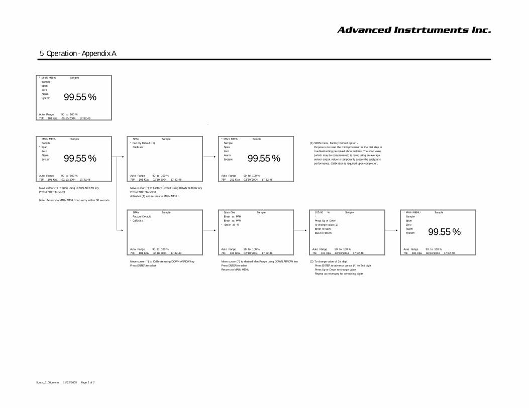
Advanced Instrtuments Inc.
5 Operation - Appendix A
* MAIN MENU Sample
Sample
Span
Zero
Alarm
System
Auto Range 90 to 100 %
75F 101 Kpa 02/10/2004 17:32:48
99.55 %
MAIN MENU Sample SPAN Sample * MAIN MENU Sample
Sample * Factory Default (1) Sample (1) SPAN menu, Factory Default option -
* Span Calibrate Span Purpose is to reset the microprocessor as the first step in
Zero Zero troubleshooting perceived abnormalities. The span value
Alarm Alarm (which may be compromised) is reset using an average
System System sensor output value to temporarily assess the analyzer's
performance. Calibration is required upon completion.
Auto Range 90 to 100 % Auto Range 90 to 100 % Auto Range 90 to 100 %
75F 101 Kpa 02/10/2004 17:32:48 75F 101 Kpa 02/10/2004 17:32:48 75F 101 Kpa 02/10/2004 17:32:48
Move cursor (*) to Span using DOWN ARROW key Move cursor (*) to Factory Default using DOWN ARROW key
Press ENTER to select Press ENTER to select
Activates (1) and returns to MAIN MENU
Note: Returns to MAIN MENU if no entry within 30 seconds
SPAN Sample Span Gas Sample 100.00 % Sample * MAIN MENU Sample
Factory Default Enter as PPB * Sample
* Calibrate Enter as PPM Press Up or Down Span
* Enter as % to change value (2) Zero
Enter to Save Alarm
ESC to Return System
Auto Range 90 to 100 % Auto Range 90 to 100 % Auto Range 90 to 100 % Auto Range 90 to 100 %
75F 101 Kpa 02/10/2004 17:32:48 75F 101 Kpa 02/10/2004 17:32:48 75F 101 Kpa 02/10/2004 17:32:48 75F 101 Kpa 02/10/2004 17:32:48
Move cursor (*) to Calibrate using DOWN ARROW key Move cursor (*) to desired Man Range using DOWN ARROW key (2) To change value of 1st digit.
Press ENTER to select Press ENTER to select Press ENTER to advance cursor (*) to 2nd digit
Returns to MAIN MENU Press Up or Down to change value
Repeat as necessary for remaining digits
99.55 % 99.55 %
99.55 %
5_ops_3100_menu 11/22/2005 Page 2 of 7
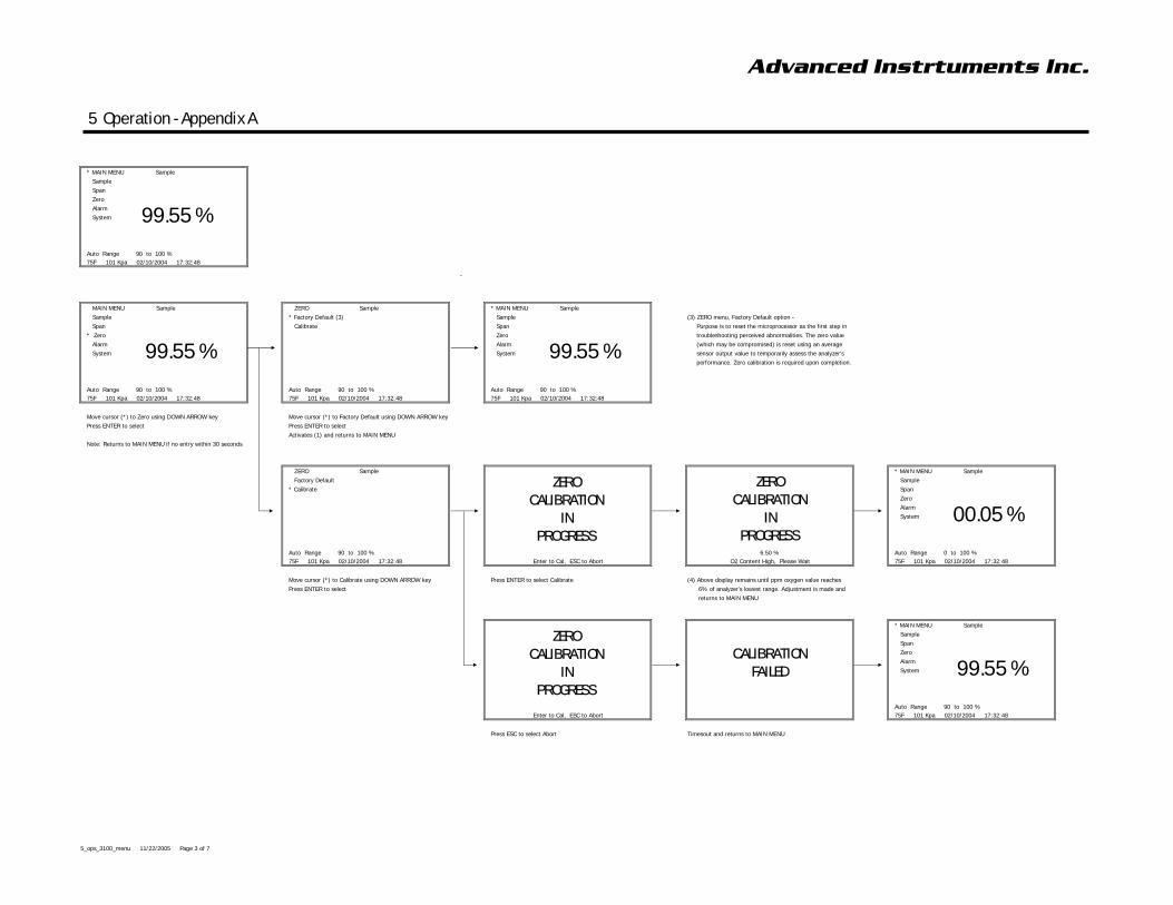
Advanced Instrtuments Inc.
5 Operation - Appendix A
* MAIN MENU Sample
Sample
Span
Zero
Alarm
System
Auto Range 90 to 100 %
75F 101 Kpa 02/10/2004 17:32:48
99.55 %
MAIN MENU Sample ZERO Sample * MAIN MENU Sample
Sample * Factory Default (3) Sample (3) ZERO menu, Factory Default option -
Span Calibrate Span Purpose is to reset the microprocessor as the first step in
* Zero Zero troubleshooting perceived abnormalities. The zero value
Alarm Alarm (which may be compromised) is reset using an average
System System sensor output value to temporarily assess the analyzer's
performance. Zero calibration is required upon completion.
Auto Range 90 to 100 % Auto Range 90 to 100 % Auto Range 90 to 100 %
75F 101 Kpa 02/10/2004 17:32:48 75F 101 Kpa 02/10/2004 17:32:48 75F 101 Kpa 02/10/2004 17:32:48
Move cursor (*) to Zero using DOWN ARROW key Move cursor (*) to Factory Default using DOWN ARROW key
Press ENTER to select Press ENTER to select
Activates (1) and returns to MAIN MENU
Note: Returns to MAIN MENU if no entry within 30 seconds
ZERO Sample * MAIN MENU Sample
Factory Default Sample
* Calibrate Span
Zero
Alarm
System
Auto Range 90 to 100 % 6.50 % Auto Range 0 to 100 %
75F 101 Kpa 02/10/2004 17:32:48 Enter to Cal, ESC to Abort O2 Content High, Please Wait 75F 101 Kpa 02/10/2004 17:32:48
Move cursor (*) to Calibrate using DOWN ARROW key Press ENTER to select Calibrate (4) Above display remains until ppm oxygen value reaches
Press ENTER to select 6% of analyzer's lowest range. Adjustment is made and
returns to MAIN MENU
* MAIN MENU Sample
Sample
Span
Zero
Alarm
System
Auto Range 90 to 100 %
Enter to Cal, ESC to Abort 75F 101 Kpa 02/10/2004 17:32:48
Press ESC to select Abort Timesout and returns to MAIN MENU
99.55 % 99.55 %
00.05 %
ZERO
CALIBRATION
IN
PROGRESS
ZERO
CALIBRATION
IN
PROGRESS
ZERO
CALIBRATION
IN
PROGRESS
CALIBRATION
FAILED 99.55 %
5_ops_3100_menu 11/22/2005 Page 3 of 7
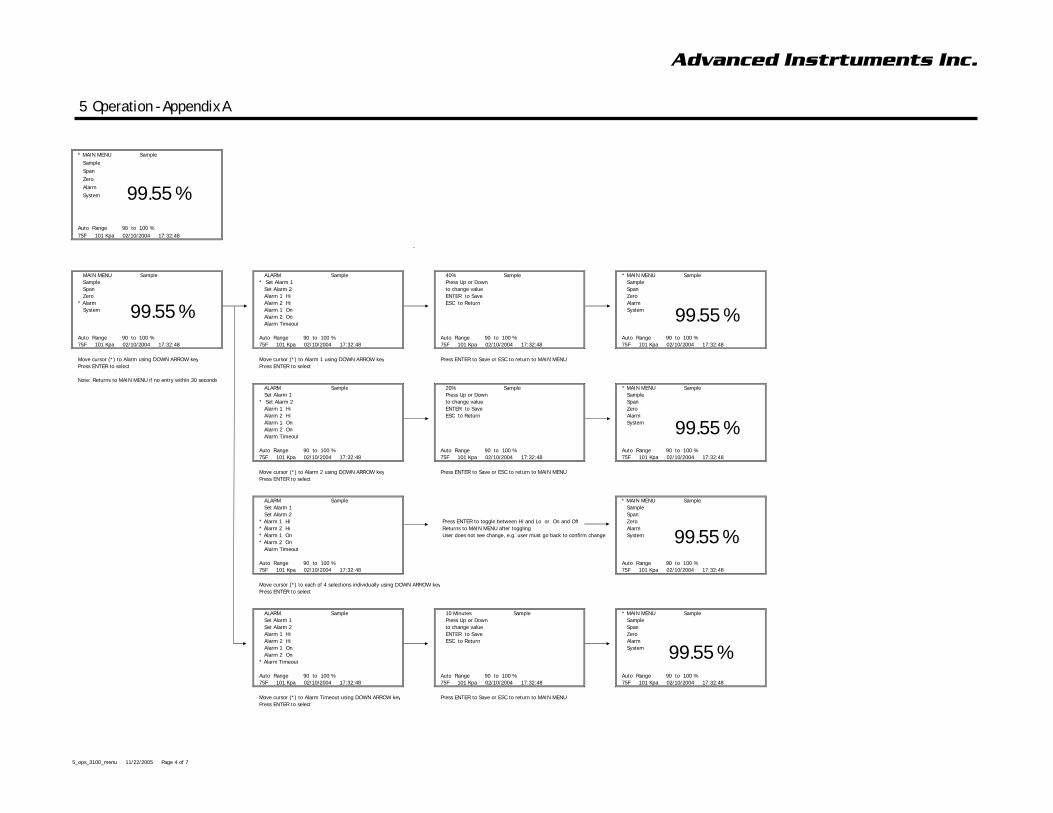
Advanced Instrtuments Inc.
5 Operation - Appendix A
* MAIN MENU Sample
Sample
Span
Zero
Alarm
System
Auto Range 90 to 100 %
75F 101 Kpa 02/10/2004 17:32:48
99.55 %
MAIN MENU Sample ALARM Sample 40% Sample * MAIN MENU Sample
Sample * Set Alarm 1 Press Up or Down Sample
Span Set Alarm 2 to change value Span
Zero Alarm 1 Hi ENTER to Save Zero
* Alarm Alarm 2 Hi ESC to Return Alarm
System Alarm 1 On System
Alarm 2 On
Alarm Timeout
Auto Range 90 to 100 % Auto Range 90 to 100 % Auto Range 90 to 100 % Auto Range 90 to 100 %
75F 101 Kpa 02/10/2004 17:32:48 75F 101 Kpa 02/10/2004 17:32:48 75F 101 Kpa 02/10/2004 17:32:48 75F 101 Kpa 02/10/2004 17:32:48
Move cursor (*) to Alarm using DOWN ARROW key Move cursor (*) to Alarm 1 using DOWN ARROW key Press ENTER to Save or ESC to return to MAIN MENU
Press ENTER to select Press ENTER to select
Note: Returns to MAIN MENU if no entry within 30 seconds
ALARM Sample 20% Sample * MAIN MENU Sample
Set Alarm 1 Press Up or Down Sample
* Set Alarm 2 to change value Span
Alarm 1 Hi ENTER to Save Zero
Alarm 2 Hi ESC to Return Alarm
Alarm 1 On System
Alarm 2 On
Alarm Timeout
Auto Range 90 to 100 % Auto Range 90 to 100 % Auto Range 90 to 100 %
75F 101 Kpa 02/10/2004 17:32:48 75F 101 Kpa 02/10/2004 17:32:48 75F 101 Kpa 02/10/2004 17:32:48
Move cursor (*) to Alarm 2 using DOWN ARROW key Press ENTER to Save or ESC to return to MAIN MENU
Press ENTER to select
ALARM Sample * MAIN MENU Sample
Set Alarm 1 Sample
Set Alarm 2 Span
* Alarm 1 Hi Press ENTER to toggle between Hi and Lo or On and Off Zero
* Alarm 2 Hi Returns to MAIN MENU after toggling Alarm
* Alarm 1 On User does not see change, e.g. user must go back to confirm change. System
* Alarm 2 On
Alarm Timeout
Auto Range 90 to 100 % Auto Range 90 to 100 %
75F 101 Kpa 02/10/2004 17:32:48 75F 101 Kpa 02/10/2004 17:32:48
Move cursor (*) to each of 4 selections individually using DOWN ARROW key
Press ENTER to select
ALARM Sample 10 Minutes Sample * MAIN MENU Sample
Set Alarm 1 Press Up or Down Sample
Set Alarm 2 to change value Span
Alarm 1 Hi ENTER to Save Zero
Alarm 2 Hi ESC to Return Alarm
Alarm 1 On System
Alarm 2 On
* Alarm Timeout
Auto Range 90 to 100 % Auto Range 90 to 100 % Auto Range 90 to 100 %
75F 101 Kpa 02/10/2004 17:32:48 75F 101 Kpa 02/10/2004 17:32:48 75F 101 Kpa 02/10/2004 17:32:48
Move cursor (*) to Alarm Timeout using DOWN ARROW key Press ENTER to Save or ESC to return to MAIN MENU
Press ENTER to select
99.55 % 99.55 %
99.55 %
99.55 %
99.55 %
5_ops_3100_menu 11/22/2005 Page 4 of 7
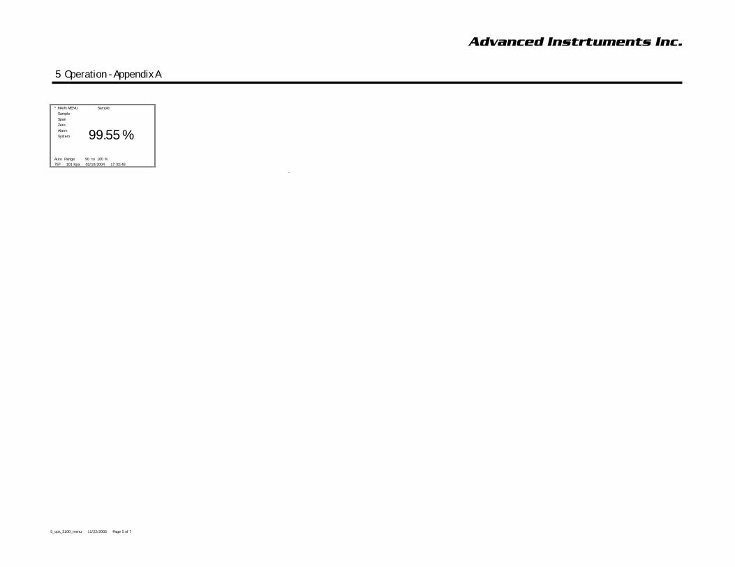
Advanced Instrtuments Inc.
5 Operation - Appendix A
* MAIN MENU Sample
Sample
Span
Zero
Alarm
System
Auto Range 90 to 100 %
75F 101 Kpa 02/10/2004 17:32:48
99.55 %
5_ops_3100_menu 11/22/2005 Page 5 of 7

Advanced Instrtuments Inc.
5 Operation - Appendix A
* MAIN MENU Sample
Sample
Span
Zero
Alarm
System
Auto Range 90 to 100 %
75F 101 Kpa 02/10/2004 17:32:48
99.55 %
MAIN MENU Sample * SYSTEM
Sample Enable Low Flow Alarm If active, press ENTER to toggle between Enable and Disable
Span Disable Alarm During Cal Press ENTER to toggle between Enable and Disable
Zero Signal Average Low, Medium or High (default Medium) - response time vs. noise filtering
Alarm Range Same as SAMPLE, Manual Ranging above
* System Logging Interval
Temp co-efficient Not active at this time
View Data Graph Fullscreen display of data points - provided Logging On
Set Clock (and Date)
Auto Range 90 to 100 % Logging On Press ENTER to toggle between On and Off
75F 101 Kpa 02/10/2004 17:32:48 Show Text Press ENTER to toggle between MAIN MENU display options - 1.) menu text with large numbers or 2.) menu text with small number and graph
Display Negative (Reading) On Press ENTER to toggle between On and Off
Move cursor (*) to Systemusing DOWN ARROW key
Press ENTER to select
Note: Returns to MAIN MENU if no entry within 30 seconds 75F 101 Kpa 02/10/2004 17:32:48
Move cursor (*) to desired selection using DOWN ARROW key
11 Minutes
Press Up or Down
to change value
ENTER to Save
ESC to Return
75F 101 Kpa 02/10/2004 17:32:48
Press ENTER to Save and return to SYSTEM menu
Press ESC to Return to SYSTEM menu
SET CLOCK * SET CLOCK * MAIN MENU Sample
* Set Time Set Hour Sample
Set Date Set Minute Span
Set Second Zero
Alarm
System
Auto Range 90 to 100 %
75F 101 Kpa 02/10/2004 17:32:48 75F 101 Kpa 02/10/2004 17:32:48 75F 101 Kpa 02/10/2004 17:32:48
Move cursor (*) to desired selection using DOWN ARROW key Move cursor (*) to desired selection using DOWN ARROW key
Press ENTER to select Press ENTER to select
Press UP or DOWN arrows to change value
Returns to MAIN MENU
Repeat for each selection option
* SET DATE * MAIN MENU Sample
Set Year Sample
Set Month Span
Set Day Zero
Alarm
System
Move cursor (*) to desired selection using DOWN ARROW key
Press ENTER to select Auto Range 90 to 100 %
Press UP or DOWN arrows to change value 75F 101 Kpa 02/10/2004 17:32:48 75F 101 Kpa 02/10/2004 17:32:48
99.55 %
99.55 %
99.55 %
5_ops_3100_menu 11/22/2005 Page 6 of 7

Advanced Instrtuments Inc.
5 Operation - Appendix A
* MAIN MENU Sample
Sample
Span
Zero
Alarm
System
Auto Range 90 to 100 %
75F 101 Kpa 02/10/2004 17:32:48
99.55 %
Returns to MAIN MENU
Repeat for each selection option
5_ops_3100_menu 11/22/2005 Page 7 of 7