GPO PRICE $ CFSTI PRICE(S) $ Hard copy - NASA · GPO PRICE $ CFSTI PRICE(S) $ Hard copy Microfiche...
104
GPO PRICE $ CFSTI PRICE(S) $ Hard copy Microfiche (MF) ff 653 July 65 https://ntrs.nasa.gov/search.jsp?R=19670018380 2018-06-21T01:07:35+00:00Z
Transcript of GPO PRICE $ CFSTI PRICE(S) $ Hard copy - NASA · GPO PRICE $ CFSTI PRICE(S) $ Hard copy Microfiche...

GPO PRICE $
CFSTI PRICE(S) $
Hard copy
Microfiche (MF)
ff 653 July 65
https://ntrs.nasa.gov/search.jsp?R=19670018380 2018-06-21T01:07:35+00:00Z
_ ii i:ii_::i
v --
RESEARCH REPORT 258
THE PLASMA RADIATION SHIELD: CONCEPT,
APPLICATIONS TO SPACE VEHICLES;:"
by
.,..,.
Richard H. Levy, and Francis W. French ......
AND
AVCO EVERETT RESEARCH LABORATORY
a division of
AVCO CORPORATION
Everett, Massachusetts
Contract No. NAS 8-Z0310
April 1967
prepared for
NATIONAL AERONAUTICS AND SPACE ADMINISTRATION
GEORGE C. MARSHALL SPACE FLIGHT CENTER
Huntsville, Alabama
",-'Submitted to Journal of Spacecraft and Rockets.
e,";:=SeniorConsultant Engineer, Avco Space Systems Division, Lowell, Mass.


PRECEDING PAGE BLANK NOT FILMED.
ABSTRACT
The Plasma Radiation Shield is an active device using free electrons,
electric and magnetic fields for the purpose of shielding astronauts from
energetic solar flare-produced protons. The concept of Plasma Radiation
Shielding is reviewed in the light of current studies. The available evidence
indicates that the concept is physically sound, but important practical
questions remain in at least two areas: these have to do with establishment
and control of the extremely high voltages required, and with integration of
the concept into a realistic space vehicle design.
-iii-

t u_:_r_L_,i,d_ PAGE BLANK NOT FILM_-D,"
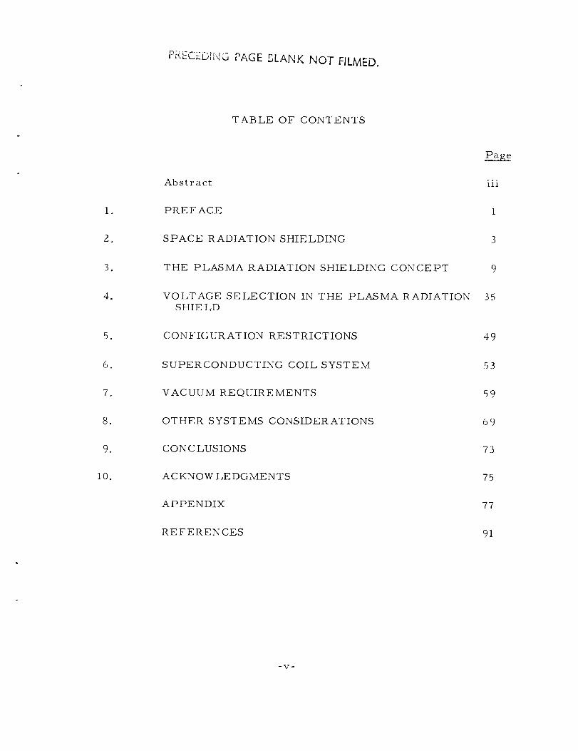
TABLE OF CONTENTS
Abstract
Pa_e
iii
I° PREFACE i
_° SPACE RADIATION SHIELDING
o THE PLASMA RADIATION SHIELDING CONCEPT
. VOLTAGE SELECTION IN THE PLASMA RADIATION 35
SHIE LD
. CONFIGURATION RESTRICTIONS 49
° SUPERCONDUCTING COIL SYSTEM 53
.
°
,
i0.
VACUUM REQUIREMENTS
OTHER SYSTEMS CONSIDERATIONS
CONCLUSIONS
ACKNOW LEDGMENTS
59
69
73
75
APPENDIX 77
REFERENCES 91
-V-


i. PREFACE
The Plasma Radiation Shield is an active device intended to protect
astronauts on long missions in deep space from the penetrating proton
radiation that follows large solar flares. The nature of the Plasma Radiation
Shield is such that it is not by any means certain that it will be successful°
However, if it is successful, it offers the prospect of radiation shielding at
a comparatively low cost in weight, provided that certain features of the
device prove to be compatible with broader aspects of the space mission
profile. Research on the Plasma Radiation Shielding principle, although
far from finished, has yielded encouraging results to the point that it seems
worthwhile to consider in a preliminary way the broader problems that must
be dealt with if the concept is to be useful in a practical sense. In this con-
text, the present paper is intended to accomplish the following objectives:
I. To explain the fundamentals of the Plasma Radiation Shielding
concept;
2. To outline the present status of research on basic aspects of the
concept, with particular emphasis on the uncertainties still to be
resolved;
3. To extract from the above a list of possible problem areas likely
to arise in integrating the Plasma Radiation Shield with a
realistic spacecraft design;
4. To discuss these problem areas in general terms, quantitatively
where possible. These discussions are viewed as being essen-
tially preliminary to a more thorough systems type study.
The organization of this paper is as follows: In Section 2 we give a
very brief summary of the nature of the space radiation shielding problem.
This summary points to the desirability of finding unconventional light-
weight shielding methods. We discuss electrostatic and magnetic shielding,
and conclude that neither of these schemes looks promising. This leaves the
Plasma Radiation Shield as the only advanced shielding concept still in the

running; the basic principles of the Plasma Radiation Shield are thoroughlydiscussed in Section 3. The two basic design parameters in the Plasma
Radiation Shield are the size and the voltage. The size is determined by
such straightforward factors as the crew size_ and compatibility with launch
vehicles. The determination of the voltage is more complicated, and is the
subject of Section 4. VVeconclude that the range fron_ 10-60 million volts
is likely to be of interest. The following sections (5 through 8) take upparticular problems of importance in adapting the Plasma Radiation Shield
concept to a space vehicle. These are, respectively, restrictions on the
configuration, the superconducting coils, the vacuum requirements, and
other miscellaneous prob|ems. Section 9 offers our conclusions from the
study; these are principally that we have succeeded in isolating the mostdifficult practical problems associated with the Plasn_a Radiation Shield,that these problems appear difficult but not insuperab!e, and that studies in
greater depth are definitely required before firmer conclusions about the
merits of the Plasma Radiation Shield can be reached. An appendix discusses
the present status of research on the physics of the underlying concept.Here again, in spite of favorable initial results, much work remains to bedone.
-2-

2. SPACE RADIATION SHIELDING
Manned space vehicles outside the geomagnetic field on lunar andinterplanetary missions are subjected to the hazards of the unattenuated
space radiation environment. Of the two principal components of this_,._.
environment, the galactic and the solar flare radiations, the latter is gen-erally considered the more important because of the large fluxes associated
with it. The solar flare radiation hazard is compounded on long durationmissions because of the integrated effects of the doses received over the
extended mission. Vehicles orbiting the earth at high (e. go, synchronous)
altitudes are subjected to much the same environmental components as well
as to the protons and electrons associated with the outer edges of the trappedradiation belts. Since inadequate radiation protection can result in absorbed
doses that cause discomfort, illness, and even (in extreme cases) death to
the crew, it is apparent that provisions must be made to limit the anticipatedradiation doses to acceptable levels.
There is a wide variation in opinion {e.g., Refs. I to 29) concerningthe degree of hazard posed to astronauts by solar flares. This lack of
agreement can be attributed to two factors. First, adequate quantitative
data on the space radiation environment has only been obtained through one
We restrict ourselves to considering the radiation hazard due to naturallyoccurring charged particles. On the one hand, the dangerous portion ofthe solar electromagnetic radiation spectrum (principally the far UV) iseasily screened; on the other hand, there is no appreciable component ofneutron radiation present in space.
This is a fortunate accident, because the energies of the galactic radiationare so large that shielding against them is an order of magnitude moredemanding than in the case of solar flares, and, for practical purposes,can be considered essentially impossible. Astronauts in the foreseeablefuture will have to live with the galactic radiation; this situation is notideal, but, in quantitative terms, is probably acceptable.
-3-
solar cycle. This data suggests that it will be very @ifficult to make a use-ful art out of forecasting the occurrence of major flares. Further, the
wide range in intensity of different flares makes it difficult to predict the
confidence levels appropriate to the more intense flares. Thus, postulation
of radiation conditions to be encountered on future flights based on this
modest experience is questionable. Second, information on the responseof the human body to the type of radiations encountered in space is limited.
This deficiency is due to the lack of experience with a natural source of
protons on earth, difficulties in simulating the fluxes of high energy par-
ticles in the laboratory, and humanistic considerations which preclude theuse of human subjects for hazardous experiments.
The simplest method of providing radiation protection is to use bulk
shielding material to stop the incident radiations. For solar flare protonsand alpha particles, the most appropriate materials have low atomic num-
bers (e.g., water, polyethylene). For long-duration missions, the amount
of shielding required can be reduced if the recovery capacity of the humanbody is taken into consideration. However, there are many uncertaintiesinvolved in formulating a radiation tolerance criterion on this basis, 27,30
and the shielding requirements, while reduced, are still substantial. As an
example, the amounts of polyethylene shielding required on a two-yearMartian mission are given in Ref. 27 to be 17 gm/cm 2 using a cumulativedose criterion and 7 gm/cm Z using a criterion that takes into account
biological recovery. On the other hand, much larger figures have recentlybeen suggested, 26, 31 depending on the desired probability of not exceeding
some stated dose and the phase of the solar cycle. Some of these figuresare given in Table 2. I.
If it is desired to completely shield a cylindrical vehicle 15 ft(_4. 6 re) in diameter by 25 ft (_7. 6 m) long with 7 gm/cm 2 of material, the
shielding material would weigh about 22,000 Ibs (_i0,000 kg). An alternateprocedure to shielding the entire vehicle is to shield only a minimum-sizestorm cellar to which the crew can retire in the event of severe solar flares.
This approach, however, severely restricts the activities of the crew andprobably rules out normal flight and scientific duties for the duration of the
flare. This restriction could be particularly compromising to the success
-4-

.,,,,.
°r..I
I---I
0
©
c_
0
Eo_
L)
_ _o_o:-.I
o,_oo0eoo
o_
o
°rt
_o_o_
N eq N
U r_ _ U
eq D,I N
E EU U C_
_ E Ehi) t:_ hi) b_
_ L_ I"_
E E E E EU U _ U C_
E E E E E
E E
E E©
o < <
E
.el
_ E E
E E E
E
°,.-I
iI N _ N N
I u u u u
i E E EI _ _ _I "_ _ _-I o_ ""II
g
E _ EI _ _ _
I ,._ . _ .,,
I _ _ _
I o < o <I I_III
I
I
o_,o',
oo
II
o_ I
I|
_e
o'--
oorq
o
0
,..C
o
_._ o
_o
-,.-_ rJ
m
0
-5-

of the mission if a solar flare occurs during a crucial phase of the flight.
What is clearly needed, then, is a system that will provide adequate
radiation protection, not interfere with the normal functioning of the space-
craft, and be relatively light in weight.
From this brief survey of the space radiation shielding problem as
a whole, we wish only to draw the following conclusion: a large uncertainty
presently exists concerning the shielding that will ultimately be required.
It is therefore manifestly worthwhile to consider whether, by unconventional
means, the degree of protection afforded bya given weight can be sub-
stantially increased. This conclusion launches us into a brief review of
advanced concepts in radiation shielding. To the knowledge of the present
authors, all advanced radiation shielding schemes so far put forward have
depended on the fact that the solar flare protons (and alphas) which constitute
the hazard are charged particles and can therefore be acted upon by electro-
magnetic forces. The first of these schemes is "Pure Magnetic Shielding."
2. I Pure Magnetic Shielding
It has long been known that the spectrum of cosmic rays or solar
flare protons measured near the top of the atmosphere exhibits a low-energy
cut-off which is a strong function of geomagnetic latitude. 32 This phenom-
enon is due to the fact that charged particles are able to cross a quantity of
magnetic field lines that increase with their energy; it is clearly possible
for a particle to arrive at either magnetic pole without crossing a single
field line; on the other hand, the equatorial regions are strongly protected
by the geomagnetic field. "Equatorial" in this sense means within, say,
45 ° of the geomagnetic equator. These equatorial regions have, therefore,
been the scene of all U. S. manned space flights so far. It is clearly pos-
sible to achieve a protective effect of this type for space vehicles far from
the earth by carrying an appropriate magnetic field coil; this possibility33-42
{known as pure magnetic shielding) has been studied a good deal.
We note first that the method is equally valid for charged particles of
either sign. It appears that the method has a certain promise 43'44 when it
is desired to shield against electrons in the energy range up to several
MeV; these occur in the form of trapped particles at certain locations in
-6-

the geomagnetic field, but are essentially unknown in deep space. Magnetic
radiation shielding of the type in which the field extends to "infinity" isparticularly attractive in this application since the radiation hazard caused
by the electrons is not due so much to the penetration of the primary elec-
trons, as to the comparatively long range of the secondary x-rays and-rays produced by stopping the electrons. These secondaries are absent
in the magnetic radiation shield.
Whereas pure magnetic radiation shielding against trapped electrons
looks attractive today, the same cannot be said of using pure magneticradiation shielding against solar flare protons in deep space. The reasons
for this situation are strictly quantitative; the solar flare protons against
which it is desired to shield have higher rigidities than the trapped elec-
trons, and therefore require more intense magnetic fields to do the job.
The situation has been studied both roughly and carefully; the conclusion
is always that except for cases where it is desired to stop very energetic(_ l BeV) protons from penetrating into large volumes, the weight advan-
tage of pure magnetic shielding over solid shielding is not great enough to
compensate for the substantially reduced reliability and increased com-
plexity of the active system. This conclusion can probably be regarded asdefinitive.
2.2 Pure Electrostatic Shielding
There are two forms of pure electrostatic shielding, and neither is35
sound. In one scheme, the space vehicle is pictured as being constructed
of two concentric shells, these shells to act as a charged capacitor. In
this arrangement the space vehicle as a whole is electrically neutral. In45
the other arrangement, the space vehicle is considered as a charged con-.,p
ductor at some potential relative to "infinity. ''" Without going into great
detail the difficulty with the first scheme is technical; the largest steady
voltages produced on earth between conductors are found in Van de Graaff
machines. The massiveness of these machines, which nevertheless cannot
attain voltages as high as 20 MV, speaks for itself. It is virtually certain
The meaning of this is explained in detail in connection with the PlasmaRadiation Shield.
-7-

that the insulators that would be required by an electrostatic space shielding
system would weigh far more than the solid material required to do thesame shielding job.
The difficulty with the second scheme is, perhaps, slightly less
obvious. It might be thought in the first instance that the very high vacuumprevailing in deep space would itself be a very good insulator. This is not
the case, however, since the solar wind fills the planetary system with free
protons and electrons to a density of about 10/cc. These charges are freeto respond to an electric field of the type here considered and would dis-
charge any substantial potential of either sign in a very short time. This is
particularly true if (as is always the case) one tried to maintain the spacevehicle positive as a protection against energetic protons. The free elec-
trons in space would discharge the potential in a time so short that thescheme becomes quite unrealistic.
From the foregoing it is clear that (in our opinion) neither pure
magnetic nor pure electrostatic radiation shielding looks attractive;
furthermore, the limitations on both these methods are of a sufficientlyfundamental character that it is very unlikely that our conclusions could besubstantially modified by technological developments. This situation leaves
the field of "active" radiation shielding open to the only other scheme of
this type which has been put forward. This is the so-called "Plasma
Radiation Shielding" scheme which is the principal subject of this paper andto which we now turn our attention.
-8-

3. THE PLASMA RADIATION SHIELDING CONCEPT
3. [ Plasma Radiation Shielding
The Plasma Radiation Shield 46' 47 involves the use of both electric
and magnetic fields, but the specific purposes of the two fields are as follows:
the electric field is the direct means of providing the shielding against
energetic protons, while the magnetic field has the sole purpose of support-
ing the electric field. It follows that the electric field that is required for
the Plasma Radiation Shield is just the same as that required for the pure
electrostatic shield. We therefore require the establishment of a voltage on
the order of 30-100 MV, i.e. , higher than has ever been achieved on earth.
Now, while the achievement of such voltages must obviously remain in doubt
until positively demonstrated, we hope to show in this paper that under the
special conditions of deep space there are sound reasons to hope that such
voltages are in fact attainable.
In the remainder of this section, we will present the basic features
of the Plasma Radiation Shield. The sections that follow are devoted to pre-
liminary discussion of various aspects of the Plasma Radiation Shield viewed
as a single system in an integrated space vehicle. An appendix describes the
current status of research on the problems associated with the basic physics
of the Plasma Radiation Shielding concept.
3.2 Electrostatics
We consider first the electrostatic meaning of "potential of a space
vehicle with respect to infinity." Now engineers in general are used (for
good reasons) to considering virtually any electrical device in terms of the
voltages applied or induced between pairs of terminals. In view of this, it
is a surprising fact that the concept of a voltage between a conductor and
infinity is normally the very first subject introduced in elementary electro-
statics. We generally consider a conducting sphere of radius a carrying a
positive charge Q on its surface; the electric field produced by this
arrangement (in the absence of other charges) is radially outwards from the
-9-

surface of the sphere. The magnitude of this radial electric field at radius
r(> a) is E - QrZ and this field can be derived from a potential
4,v6 0
- Q (3. z. i)
In defining the potential an arbitrary constant may always be added; in this
case we have assumed that _b = 0 at a large distance from the sphere. It
follows that the sphere is at a potential
Q
(a) - 4=¢0 a (3. Z.2)
above the potential of distant space. A way of interpreting this statement in
terms relevant to the Plasma Radiation Shield is as follows: the work
necessary to bring a proton (of charge +e) from infinity to the surface ofeQ
our sphere is just e,%(a) - 4_c0 a In space the <:_n_ysource of this
energy is the kinetic energy of the proton when at infinity; only if this
exceeds the quantity e{,_(a) will the proton be able to r<_ach the surface of
the sphere. Measuring this kinetic energy in electron volts we find (since
the charges on an electron and a proton are of equal magnitude) that the
sphere is electrostatically shielded against protons having less than 6(a)
electron volts. If we wish to exclude protons up to 50 MeV, 6(a) must
have the value 5 x 10⁷ volts.
For a capacitor of capacitance C , the charge and the voltage are
related by the formula
Q : C6 (3. z.3)
Comparing this with the formula (2) we see that the capacitance of the
isolated sphere is C : 47,(0 a . Thus, a two-meter radius isolated sphere
-10-

-12farads = 222 picofarads.has the capacitance 222 x I0 It follows that if
we wish 4(a) to be 5 x 10⁷ volts, the charge Q must be II. I x 10-3
coulombs = I I. I millicoulombs.
Now, as was explained in connection with pure electrostaticradiation shielding, the arrangement described is not, as it stands, satis-
factory. This is because a positive charge of the magnitude being considered
would attract electrons from the surrounding space plasma at a rate so largeas to make the whole concept useless. In the Plasma Radiation Shield, the
vehicle is surrounded by a cloud of free electrons, the cloud being held inplace by a magnetic field. Now the voltage across the electron cloud is
always fixed by shielding considerations, but the details of the way in whichthe electron cloud is distributed are quite difficult to calculate. However,
any given distribution can be characterized by a capacitance C , which,
through (3.2. 3) will determine the required charge. In this section we shall
discuss briefly two geometrical arrangements which are intended to conveya general picture of the electrostatic arrangement of the Plasma RadiationShield, without simulating the geometrical details.
Consider first the situation that arises if the sphere of the previous
example is surrounded by a larger concentric conducting sphere of radiusb' . The capacitance between the two spheres is
4=_0ab' iC = = 4_E0a (3.2.4)a
b'-a I -
If b' = 4 meters and a remains 2 meters, this is 444 picofarads. To
maintain a potential difference of 5 x 10⁷ volts between the spheres requires
a charge of 22.2 millicoulombs. Now, if the large sphere carries a charge
of - 22.2 millicoulombs, the combination of two spheres carries no net
charge, and it follows that the electric field is entirely confined to the space
between the two spheres. Thus it does not attract electrons from the sur-
rounding space plasma and thereby overcomes the objection to the single
sphere model. In terms of the Plasma Radiation Shield the inner sphere is
-ll-

7not only at a potential 5 x i0 volts higher than the outer sphere; it is also
75 x 10 volts above the potential of "infinity". Suppose that the outer sphere
is transparent to protons; then a proton of 50 MeV kinetic energy approach-ing the arrangement from a large distance will be unaware of the existence
of the spheres until it penetrates the outer one. Then, as it travels into
regions of higher potential its kinetic energy will fall until it is brought torest at the surface of the inner sphere. At this point, it will start to fail
back towards the outer sphere. When it recrosses the surface of this sphere,
it will have reacquired its initial energy of 50 MeV and will retain this energyin its further travels.
The example just discussed is in many ways a fair idealization of
the electrostatic aspects of the Plasma Radiation Shield, even though thespherical geometry is not representative of the Plasma Radiation Shield.
If we continue to ignore this difference, we can regard the inner sphere asrepresenting the space vehicle. But we have already (in the discussion of
pure electrostatic radiation shielding) dismissed the possibility that theouter sphere could be a solid electrode for the reason that the insulators
separating the spheres would surely weigh more than a solid material
radiation shield. In the Plasma Radiation Shield the outer sphere is replaced
by a distributed cloud of electrons held in place by a magnetic field of
moderate intensity. Therefore, in our second example, we imagine a cloudof electrons to be distributed around the inner sphere in such a manner that
their number density n (i.e. the mean number of electrons per cubicemeter) is a function only of r . For the moment we shall just suppose that
they are held in place by "magic". Later we shall discuss this obviously
vital question in detail. Clearly, the electron cloud is completely trans-parent to incoming protons in the sense of the discussion of proton reflectiongiven earlier.
Poisson's equation connects the potential with the charge density.
In the present spherically symmetric situation we have:
i d
r dr 2 d#)] n (r)e
er --
dr _0
-12-

Now for simplicity, suppose that the electron distribution is one of constant
density n extending between the surface of the inner sphere {radius a )e
and some larger radius b . This distributed electron cloud represents the
outer sphere of the previous example; the electron cloud therefore contains
a total charge Q given by:
Q _ 4 33 _ (b3 a }nee (3.2.5)
The appropriate solution of Poisson's equation, valid for a _< r _< b can
now be shown to be:
_(r) - Q (b - r)Z(b + r/2) (3.2.6)
4,_ff0r (b3 _ a 3}
The potential at r = b is zero, as is also the potential of all points r > b .
The electric field at r = b is also zero because there is no net charge
inside this radius. The electric field also vanishes for r > b . It follows
now that the potential of the "space vehicle" is higher than the potential at
"infinity" by the amount
(a) - Q (b - a)(b + a/Z) (3 2 7)
4_0a b2+ab+a 2 " .
For a given value of _(a) , (b(r) can be written in the form:
d)(r) = (_(a) • (1 -r/b)2(1 + 2b/r)
(1 - a/b)2(1 + 2b/a)(3.2.8)
For vario_s values of b/a , this variation in 6(r) across the electron
-13-
cloud is shown in Fig. 3. io
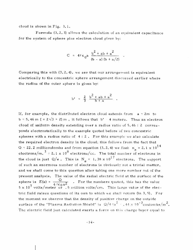
Formula (3.2. 3) allows the calculation of an equivalent capacitance
for the system of sphere plus electron cloud given by:
C = 4v_0a
b 2 + ab + a 2
(b - a)(b + a/Z)
Comparing this with {3. Z°4), we see that our arrangement is equivalent
electrically to the concentric sphere arrangement discussed earlier where
the radius of the outer sphere is given by:
2 b 2 + ab + a 2b w -
3 b+a
If, for example, the distributed electron cloud extends from a --2m to
b = 5.46m ( = 2 _,F3+ 2)m , it follows that b' - 4 meters. Thus an electron
cloud of uniform density extending over a radius ratio of 5.46 : 2 corres-
ponds electrostatically to the example quoted before of two concentric
spheres with a radius ratio of 4 : 2 . For this example we also calculate
the required electron density in the cloud; this follows from the fact that
14Q = 22.2 millicoulombs and from equation (3.2.4) we find: n = 2. I x 10
e
electrons/m. 3 = 2. i x 108 electrons/cc. The total number of electrons in
• I017the cloud is just Q/e This is N = I. 38 x electrons. The supporte
of such an enormous number of electrons is obviously not a trivial matter,
and we shall come to this question after taking one more number out of the
present analysis. The value of the radial electric field at the surface of the
sphere is E(a) - Q For the numbers quoted, this has the value=E 0 a 2
5 x 10⁷ volts/mete 4 or . 5 million volts/cm. This large value of the elec-
tric field raises questions of its own to which we shall return (in 3. 5). For
the moment we observe that the density of positive charge on the outside
2 -3 c 2surface of the "Plasma Radiation Shield" is 6]/4_7a .44 x I0 oulombs/m
The electric field just calculated exerts a force on th_ charge layer equal to
-14-

wn_WT
"--" 0
d d
Z ZW W
1.0
0.5--
I I ' I
POS,Z,VE CHARGED -------._/
SPHERE _ o
L RADIUS OF ELECTRON CLOUD b
I 2 5 4,-r
5_
Fig. 3.1 Distribution of potential outside a charged sphere in the
presence of an electron cloud of uniform density extending
from the sphere (radius a ) to radius b . The negative
charge in the electron cloud is equal in magnitude to the
positive charge on the sphere.
-15-
A5731

Ii x 10 5 newtons/m 2• _ .II atmospheres. This force can also be thought
of as the force of attraction between the positive charg_ +Q on the inner
sphere and the negative charge -Q in the electron clo_Ld. The nature of
this force is the same as that of a gas atmosphere at this pressure inside
the sphere; the magnitude would not be such as to cause much of a structural
problem.
The preceding discussion of the electrostatic situation near a
"Plasma Radiation Shield" of spherical geometry gives an idea of the way
in which the electric fields are distributed around the space vehicle, and
also gives a preliminary indication of the orders of magnitude of the quan-
tities involved; we turn next to the means by which a magnetic field can be
used to hold the electron cloud in place.
3. 3 The Magnetic Field
The force exerted on an electron of charge -e moving with velocity
v in a magnetic field B is -e(vx B) . This force has no component
parallel to _B , and from this observation follow important consequences.
For, should there be any electric field in the direction of the magnetic field,
the electrons will respond immediately by flowing along it until it is essen-
tially nullified. It follows that after a very short time magnetic field lines
(or at least those portions of the magnetic field lines on which there are
electrons) will have no electric field along them, or, what is the same thing,
they will become equipotentials. Now, since "infinity" and the space vehicle
are supposed to differ in potential by 5 x 10 7 volts, there can be no lines of
force which in one place are near the space vehicle and in another place far
away from it. There is really only one kind of magnetic field geometry that
satisfies both this requirement and the additional requirement that the field
be outside the space vehicle, and that is, in its simplest form, the magnetic
field due to loop of current, illustrated in Fig. 3.2. T_ be more precise,
one would like to make the surface of the vehicle correspond in form to a
given magnetic field line. This can be accomplished in a large variety of
ways, but all these are topologically the same as the single loop coil shown
in Fig. 3.2. Thus, the simple observation that v x i_ is perpendicular to
B leads us to reject the possibility of a spherical Plas_Ta Radiation Shield
- i_-

/- AX IS OF
MAGNETIC FIELD,LINES
CURRENT LOOP
Fig. 3.2 A loop current is the simplest form of magnet giving a
field shape satisfying the requirements of the Plasma
Radiation Shield. This illustration shows the general
shape of the magnetic field lines surrounding such a loop.
-17-
A742=2

in favor of a topological torus. The condition that a space vehicle utilizing
the Plasma Radiation Shield be a topological torus is on examination not as
restrictive as one might suppose, although it does ru|e out direct adaptation
of shapes not satisfying this condition. There are an unlimited number of
ways in which a topological torus can be deformed; two examples are shown
in Figs. 3. 3 and 3.4. Of these two, the first represents a more substantial
departure from current thinking about the shape of space vehicles than the
second. Several other possibilities are discussed in Section 5 under the
general heading of Vehicle Configuration Possibilities. For the present, we
note that the configuration of Fig. 3.4 may have important advantages,
although, pending further study, these remain uncertain. A brief discussion
of these advantages is given in Section 3. 6.
A second observation of considerable importance also follows
directly from the form of the expression (v x B1 for the force exerted on an
electron by a magnetic field. That is that the force is zero when the elec-
tron is stationary. But since a force is obviously required to counteract the
electric field, the electrons must be (on the average) in motion. Thus, we
are seeking a dynamic rather than a static equilibrium. The electron cloud
must be permanently in motion of a rather complicated kind, and this motion
must be so accurately perpendicular to the electric field that the electrons
do not reach the space vehicle in a time comparable to the duration of a
solar flare (i.e., about 48 hours). The nature and present state of under-
standing of this dynamic equilibrium are briefly discussed in Section 3.4
and in the Appendix. For the present we note only that the dynamics of the
electron cloud poses many problems concerning which our present knowledge
is incomplete.
One further conclusion to be reached on the basis of the force
expression is quantitative. The magnitude of the magnetic force is evB .
The electric force which this is supposed to counterbalance is eE .
Equating these yields
EB = E/v - , where _ = v/c (3. 3. i)
_c
-18-

MAGNETICFIELD
ELECTRON CLOUD DRIFT ."
CRYOGENICINSULATION
Fig. 3. 3
SUPERCONDUCTOR;OUTER SHELL
SPACE SH IPINTERIOR
Shows how the simple loop current shown in Fig. 3.2 can
be adapted to a space vehicle. In this particular realization,
the vehicle is symmetric in azimuth around the axis of the
loop. Also shown are the electron cloud with its associated
direction of drift, and a possible 4-coil arrangement for the
superconducting magnet. The double-walled construction is
discussed in Section 7. Of the many other realizations of the
Plasma Radiation Shield that are possible, one more is
shown in Fig. 3.4.
-19-
A2089

/
//
/ OUTER SPACE p I0 -15 TORR/'
/ ,.. .. _io \
I- INSULATING STRUTS
2-MAGNETIC FIELD COILS5- NON-BAKEABLE INNER SKIN
4-BAKEABLE OUTER SKIN
5-INNER SPACE,p,,10 -9 TORR6-EXIT PORT WITH VITON "0"
RING SEAL
7-EQUIPOTENTIAL SURFACES
8-MAGNETIC FIELD LINES9-LIVING & WORKING SPACE
p,,5 psi
IO-LIMITS OF ELECTRON CLOUD
It- ANTENNAS ETC.
Fig. 3.4 Possible alternate conceptual configuration for a Plasma
Radiation Shielded space vehicle. This speculative config-
uration could utilize a cylindrical launch vehicle. The
relative merits of this approach are discussed in Section
3.6. The equipotentials follow magnetic field lines in the
interior of the electron cloud, but are distinct outside of the
cloud.
-ZO-
A7807

and if we knew v this would determine B since E is fixed by the electro-
statics of the situation. But an absolute upper limit to v is given (by the
theory of relativity) as the speed of light c = 3 x 10⁸m/sec. Using the value
of E = 5 x 10⁷ volts/m and assuming that the electron velocity can be one-
half of its maximum value (i.e., _ = I/2), we find a characteristic magnetic
field of . 33 webers/m Z, or 3.3 k gauss. This magnetic field is far below
what would be required for a pure magnetic radiation shield. Note also that
it depends directly on our assumption about the electron velocity. Here
again is a case where necessary basic knowledge is lacking; in this case if
the _ chosen to be I/2 had been in fact 1/10, the magnetic field would have
been 5 times more intense than the 3. 3 k gauss quoted. This would give a
magnetic field comparable in strength to that required for a pure magnetic
shield, and we already know that the weight of these devices makes them
unattractive. On the other hand, it may be permissible to go the other way;
perhaps _ can be as high as 0.9, giving a magnetic field of only 1.9 k gauss.
This large uncertainty has a considerable effect on the calculated weight of
the Plasma Radiation Shield, since the superconducting magnetic field coil
(with its structure, insulation, power supply, controls, etc.) is the only
massive item in the Plasma Radiation Shield. Up to the present, it has been
guessed that 6 = i/2 and all estimates have been based on this guess. The
factors that determine the largest achievable _(< l) are not yet fully
understood.
A final point to consider in connection with the magnitude of the
magnetic field is the following: although low values of the mean magnetic
field appear attainable, this by itself does not necessarily represent an
optimum design. A more meaningful quantity is the total magnitude of the
magnetic field energy. Now this total energy varies as the square of the
mean magnetic field, and the cube of some linear dimension. It may very
well turn out to be desirable to utilize larger mean magnetic fields over
smaller volumes. Study of this trade-off is likely to be an important
element in a deeper systems study of the Plasma Radiation Shield. In par-
ticular, the configuration illustrated in Fig. 3.4 (and briefly discussed in
Section 3. 6) would probably operate with rather substantial fields
-21-
(10-30 k gauss) in the relatively small interior volume. The most impor-tant unknown in this trade-off is the way in which the shielded volume varies
with magnetic field energy.
3.4 Containment of the _lectron Cloud
The fundamental idea underlying the concept of the Plasma Radiation
Shield is certainly sound in principle. However, although a magnetic field
as described is capable of holding the electron cloud in place, many difficult
problems must be solved before it can be stated with assurance that this
capability can actually be realized. The basic problem is that the electron
cloud has a strong tendency to collapse onto the Plasma Radiation Shield;
from the thermodynamic point of view this tendency is due to the very large
free energy associated with the electric field. The Plasma Radiation Shield
will work if it turns out that all the means available to the electron cloud of
giving up its free energy operate at acceptably low rates.
The quantitative definition of "acceptably low" turns out to be very
restrictive. Specifically, the electrons in the cloud are held at a distance
from the space vehicle by the magnetic field; various mechanisms will allow
the electrons to cross the magnetic field at appropriate speeds, and to fall
into the space vehicle. Such motion constitutes a loss current. Plainly,
this loss current must be extremely small if all the electrons (and hence the
protective electric field) are not to be lost in a time short in comparison
with the duration of a solar flare. If we take this time to be 2 days _ Z x 105
seconds, and take the total charge in the cloud to be .022 coulombs, the loss
current due to all losses should be substantially less than . iIi_ amps. A
current of this magnitude crossing a voltage of 5 x 10⁷ volts yields a maxi-
mum acceptable loss power of 5.5 watts. Put somewhat differently, at a
speed of I/Zc, an electron will drift around the Plasma Radiation Shield in
a time of about . l_z secs. Thus the mean direction of drift must be perpen-
dicular to the magnetic field to an accuracy of roughly [ part in 1012 (or
I0 5 secs/, l/J. secs).
3.4. I Instabilities
By far the most dangerous possibility is that the electron cloud
would be unstable. By this we mean that some collective effect in the
-ZZ -

electron cloud could cause the cloud to fall across the magnetic field on a
large scale. But the times associated with inherent instabilities of the
usual kind would be expected to correspond to the inherent time scales of
the electron cloud. These time scales are typically on the order of the
time it takes an electron to drift around the device (i.e., .Ip sec), or,
even shorter, the electron plasma period, or even the electron cyclotron
period. These times are so extremely short that it is vital for the success
of the concept that the electron cloud be exceedingly stable. It is a fortunate
fact that prolonged and careful study of the question of stability has yieldedconsistently encouraging results. The details of these studies are given in
Ref. 48 to 53; but a summary of the results suggests that if the inner edge
of the electron cloud is maintained very close to the surface of the space
vehicle, stability can be attained. There is also empirical evidence that a54
small-scale device (the Vac-Ion Pump) which is closely related to the
Plasma Radiation Shield is successful only because electron clouds of our
type are in fact very stable. Our own experiments have also suggested the
same, but there is an important proviso: no experiments have been done in
the geometry demanded by the Plasma Radiation Shield concept. Since cer-
tain possible modes of instability are strongly dependent on geometricalfactors, it will ultimately be necessary to test the stability of the Plasma
Radiation Shield in a direct manner. At present, all that we can say is
that experimental, empirical, and theoretical evidences are all sufficiently
encouraging to proceed to other (generally slower) forms of loss on theassumption that the hoped for stability is in fact present. The question of
stability is discussed in somewhat greater detail in the Appendix.3.4.2 Classical Diffusion
These other, slower forms of loss come generally under the heading
of "classical diffusion" caused by close collisions of the electrons with
(I) other electrons; (2) ions; (3) neutral atoms and (4) particulate matter.
We deal with these possibilities in order.
(1) Electron-electron collisions. Collisions between like particles
cause only a very weak form of diffusion, when there is a
gradient of density or temperature. Calculations indicate that
losses from this source are less than 0. 1 watts, and are
-23 -

(2)
(3)
therefore well within the allowable maximum diffusion rate.
Electron-ion collisions. These are no problem in the Plasma
Radiation Shield for the following reasons: positive ions are
strongly expelled from the electron cloud by the electric field
and are sufficiently massive that the magnetic field cannot
restrain them. The residence time for a typical ion in this-7
field is on the order of l0 seconds, and this time is so short
that the ion will generally have no close collisions with elec-
trons of the cloud. This is true of the solar flare ions, and
also of any other ions that from time to time might be present
in the system. In particular, ions coming from outside the
cloud (i.e., from space) are reflected elastically by the
electric field with no net exchange of energy.
Electron-neutral collisions. Due to solar UV radiation and
other effects, the ambient density of neutral atoms in deep
space is negligible, but there will be atoms coming out of the
space vehicle due to leaks from the pressurized cabin, and to
outgassing from exposed surfaces. The Plasma Radiation
Shield concept puts a very severe restriction on the flux of
these atoms, for the following reasons: an atom coming off
the space vehicle wilt generally be moving at a speed corres-
ponding to the temperature of the surface from which it came.
These speeds are generally moderate, and the atom is at once
exposed to the circulating flux of electrons in the cloud. If these
electrons have a density of 108/cm 3, and a speed of 1010cm/sec,
and if we take the cross section for ionization as l0 -18 2cm , the
length of time that elapses before the atom is ionized will
generally be about 1 sec. This suggests that a non-negligible
fraction of the neutral atoms coming off the space vehicle will
be ionized during their passage across the electron cloud. Now,
after ionization an electron and a positive ion are formed; the
electron will become just part of the electron cloud, but the
ion, unrestrained by the magnetic field on account of its greater
-24-

(4)
mass, will be ejected into deep space by the electric field in
the time 10 -7 seconds previously quoted. But the transport of
a positive ion from some point rear the surface of the space
vehicle to infinity is just as much a loss as is the transport of
electrons from the outer regions of the cloud to the surface of
the space vehicle. In the worst case, all the ions are formed
right at the surface of the space vehicle and subsequently
ejected across the full 5 x 10⁷ volts. In this case the limit on
the current of ions is about . I_ amps. This represents a maxi-
mum allowable number of such ions on the order of 1012/sec,
and this is also the maximum allowable rate of escape of
neutral atoms from the active space vehicle. If this is a leak
of oxygen from the cabin, it corresponds to an allowable leak
rate of about 10 -6 grams of oxygen in two days! In fact, the
mean potential at which neutrals are ionized can be considerably
lower than 5 x l07 volts, since in the I sec mean free time
estimated above the neutrals would cover a distance like 100 m.
or more. Suppose, for instance, that the mean potential of
ionization is only 1% of the full voltage, or 5 x 10⁵ volts. The
tolerable current is then 10_2 amps corresponding to a flux of
1014/sec, or 10 -4 gins in 2 days. However, even with these
figures, it is obvious that the cabin pressure vessel must be a
high quality vacuum vessel; if it is double-walled, however,
this low leak rate should be attainable. There is also a severe
restriction on the amount of outgassing of the whole surface
that can be permitted; this corresponds roughly to a pressure-12
over the surface of about i0 mm Hg, again a very low but
not unattainable level. It must be remembered that ample time
is generally available to bake and thoroughly clean all exposed
surfaces before activation of the Plasma Radiation Shield. We
shall return to this question in Section 7.
Particulate matter. If the surface of the Plasma Radiation
Shield is clean, no dust particles should be present on it;
-25-
preliminary activation of the electric field should help toachieve the required degree of cleanliness. There remains,
then, the flux of micrometeorites from space. If, as is
believed, 55 this flux is less than 10-8 gm/cm2/year outside
the immediate neighborhood of the earth, there should be no
problem from this source. A large meteorite might shut off
the electric field, and reactivation would take perhaps an hour
or less, but the probability of such an event coinciding with a
solar flare is reasonably low.
This completes our discussion of problems of classical diffusion;
by far the most important difficulty to have arisen is the control of leakage
and outgassing. Although difficult, it cannot be stated that this problem is
insuperable; the actual constraints that it is likely to impose are reviewed
in Section 7.
3. 5 Achievement of Very High Voltages
It was mentioned in Section 2 (in connection with electrostatic
shielding} that the required voltages are higher than any yet achieved on
earth, and the same comment applies to the Plasma Radiation Shield. It is
natural to ask, in these circumstances, how it is that _e can contemplate
reaching these voltages in the Plasma Radiation Shield. At this stage we
can do no more than explain why the effects that limit the voltage in present-
day machines do not apply to the Plasma Radiation Shield. This lack of
applicability of known limitations is encouraging, but is obviously not a
guarantee that the required voltages can be reached. This is an area in
which there can be no substitute for an experiment.
In general, the achievement of high voltages in the laboratory has
been limited by problems of breakdown. 56-64 The particular breakdown
experiments which are most relevant are those having to do with breakdown
between parallel electrodes in high vacuum conditions. It seems that the56
best available theory of how this occurs is as follows: at the negative
electrode (or cathode) the electric field points in such a direction as to draw
electrons out of the surface. A current is actually drawn by the quantum-
mechanical mechanism known as field emission. This current depends
-2() -

exponentially on the electric field and is therefore concentrated at micro-scopic projections on the cathode where the electric field is intensified.
Next, the current through these projections heats them by Ohmic dissipation.
At a certain field strength this heating is sufficient to evaporate the pro-
jections altogether; breakdown then occurs in the gas thus formed. Now, ifthis is indeed the true mechanism of breakdown, there is reason to be
optimistic where the Plasma Radiation Shield is concerned, for in our case,
there is no material cathode at which field emission can occur. The only
material electrode is the space vehicle itself, and this is the anode (positive
electrode); that is the direction of the electric field is such that it tries to
extract positive ions. From a quantum-mechanical viewpoint, the extraction
of positive ions by field emission is virtually impossible. The evidence as
regards anode field strength limitations is from the working of the positive65
ion microscope, a device in which a large cathode and a tiny anode produce
an enormous electric field at the surface of the latter. This device draws a
satisfactory ion current only when the electric field is on the order of 100
million volts/cm, a field some 100 times greater than that contemplated for
the Plasma Radiation Shield. Furthermore, this field strength produces
electrostatic forces on the order of 3,000 atmospheres, that is, on the
order of the yield strength of most materials. Microscopically, it is
l volt/angstrom. Taking l angstrom as a typical spacing between ions in a
lattice, and I volt as a typical binding energy, it is again plain why an ion
current can be drawn by an electric field of this strength. To sum up this
subject, the Plasma Radiation Shield should not be subject to high vacuum
breakdown as it is presently understood, and should not lose appreciable
ions at the field strengths contemplated. As stated before, these hopes can
only be proved sound by an appropriate experiment.
3.6 Possibilities for the Configuration of Fig. 3.4
The configuration of Fig. 3.4 may turn out to be very advantageous.
The reasons for this possibility must for the moment be regarded as specu-
lative, but nevertheless it is worthwhile to offer herewith some discussion
of these reasons. This discussion accomplishes two purposes, of which
the first is specific and the second general. The first purpose is that if the
-27-

anticipated advantages of this configuration hold up under further study, the
Plasma Radiation Shield will be substantially simpler to achieve than might
otherwise have been the case. The second purpose is to show, by means of
an example, that there is still a large amount of room for the application of
imaginative ideas to the Plasma Radiation Shield. The concept is still far
from complete definition; further study on a broad front can still be expected
to yield large as well as small changes in its overall desirability.It was stated in Section 3.2 that magnetic field lines on which there
were electrons must be equipotentials. This statement may not be strictly
true, for the following reasons: in axially symmetric magnetic fields (as,for instance, that shown in Fig. 3.2) magnetic field lines that pass close to
the axis of symmetry (say, at a radial distance rsmal I) close at a very2
large radial distance, roughly rlarg e = V/(2_rsmal l) , where V is arepresentative volume of the magnet. But since the electrons of the cloud
are attracted to the positive charge on the space vehicle, the electrons may
not wish to locate themselves quite so far away from the vehicle as rlarg e.This suggests that the electron cloud might be confined to some region nearthe space vehicle, of characteristic volume V , and that the remainder of
the magnetic field is largely, or even entirely, free of electrons. The
interpretation of the statement in Section 3. 3 about magnetic field lines
being equipotentials is then as follows: throughout the electron cloud, mag-netic field lines are indeed equipotentials, but in regions of the magnetic
field where there are no electrons, there is no such requirement. Thus, it
is possible to imagine that the equipotentials follow the magnetic field linesin the region near the axis of the magnetic field, but that outside of some
contour defining the boundary of the electron cloud, the electrostatic
potential satisfies Laplace's equation. In this case the equipotentials would
fall inside the magnetic field lines in the vacuum region, but would becometangent to the magnetic field at the boundary of the electron cloud. This
situation would not affect the basic shielding properties of the configuration.
It is not known for sure whether such an electron cloud is possible,but, on the assumption that it is, the configuration of Fig. 3.4 would have
important advantages, as follows:
-28 -

I. The shape of the magnetic field is roughly that of a long sol-
enoid; in such a magnetic field, the field lines close at larger
distances than they would, say, for the loop current of Fig. 3.2.Thus, the electron cloud should be substantially confined to theinterior of the solenoid.
2. The general shape of the space vehicle is cylindrical, in accor-
dance with many current ideas about such vehicles; such a shape
is naturally compatible with launching rockets.3. The construction of a solenoidal magnet is a simpler task
structurally than the construction of the four-coil magnet of
Fig. 3. 3. Also, the stray magnetic fields in the shielded
volume would be very small indeed.
4. Since there is essentially no electron cloud outside the vehicle,
gas atoms coming from the vehicle will not be ionized, and will
therefore constitute no electrical loss. Thus, the vacuum prob-lem (discussed briefly in Section 3.4.2, and in detail in Section
7) would be confined to the relatively small area of the space
vehicle facing the electron cloud. In particular, ports, doors,
antennas, etc. could be located on the exterior surface without
the necessity for special sealing.
5. The electric field on the outside of the space vehicle would be
quite low. Thus protuberances of various sorts could easily betolerated, and would have essentially no effect on the electroncloud.
6. The injection of the electrons could be accomplished in the low
field region outside the vehicle; these electrons would then
quite naturally proceed to the high magnetic field region inside
the solenoid. Such an injection procedure might be extremely
s imple.
In conclusion, we must emphasize that the existence of the type of
equilibrium we are considering has not yet been demonstrated. Fven less
is known about possible instabilities of such equilibrium configurations. In
particular, we do not yet know how to calculate the shielded volume
-29-

associated with such a configuration, i.e., what outer radius of the space
vehicle can be tolerated. An important effect of this ignorance is that
calculations of the weight of such a Plasma Radiation Shield are irrelevant
to the extent that we cannot associate them with definite values of the
shielded volume. Lastly, the extent of these uncertainties can be taken as
a rough measure of the present degree of definition of the Plasma Radiation
Shielding concept.
3.7 Basic Design Parameters
The most basic design parameters of the Plasma Radiation Shield
are, first, the size and shape, and second, the overall voltage. The vol-
tage is set by considering such questions as the actual frequency and spectra
of solar flares, and allowable radiation doses to the crew. This subject is
discussed in some detail in Section 4. The size is set fundamentally by the
nature of the mission to be undertaken, especially the crew size and the
mission duration, but the shape is set (as discussed in Section 3. 3) by the
requirement that the Plasma Radiation Shield be essentially toroidal. Two
possible configurations are shown in Figs. 3. 3 and 3.4, but these suggestions
are far from exhausting the possibilities.
Now a principal object of any analysis of the possibilities inherent
in the Plasma Radiation Shield must be a curve showing the relation between
the shielded volume and the systems weight. However, we are not yet in a
position to calculate either of these quantities with any precision. The
uncertainty associated with the shielded volume was discussed briefly in
Section 3.6 in connection with the configuration of Fig. 3.4, but stems basic-
ally from lack of definition of the overall configuration of the space vehicle,
magnetic field and electron cloud. The uncertainty associated with the
systems weight stems basically from a lack of definition (_fthe attainable
value of _ (Eq. 3.3. I), since this parameter determines the level of the
required magnetic field. The weight of a Plasma Radiation Shield resides
primarily in the superconducting coil. The weight of the superconductor-l
itself is proportional to _ , while the weight of its power supply and-2
structure scale with i_ The weight of the cryogenic system (including
refrigerator) depends strongly on the coil configuration. Lack of certainty
-30-

about the configuration also makes it difficult to assign a weight to other
components of the system, such as penalties associated with vacuum require-ments.
The net result of these considerations is that it is not possible, atthe present time, to calculate the weight of a Plasma Radiation Shield with
any more precision than was done in Ref. 44. The curve of weight vs.shielded volume of that paper is reproduced here, as Fig. 3.5, and indicates
clearly the advantages that may be possible with a Plasma Radiation Shield.
Since this curve was drawn, the physical basis for the concept has been
placed in a much sounder framework. Thus it is now possible to take up
again the question of systems integration; as stated in the Preface {Section I),
it is the purpose of this paper to lay the basis for such a systems study,
rather than to accomplish it. This being the case, in calculating system
weights, we leave our results for the most part as formulas, showing the
dependence of the weights of different components on characteristic param-
eters such as the magnet current. In particular, we do not attempt toestablish a sample design for which weights can be calculated, as this does
not seem presently to be justified.
3.8 Summary
To sum up, the basic features of the Plasma Radiation Shield are
as follows:
i. A cloud of electrons of total charge -Q is held away from the
space vehicle (which has a positive charge +Q) by a magnetic
field. The magnitude of Q is determined roughly by a knowl-
edge of the required voltage of the space vehicle and its size
and shape, and (to a smaller extent) by the details of the distri-
bution of the electron cloud. Potentials from i0 to, say, 200
million volts are considered. Characteristic electric fields
are on the order of I million volts/ca.
2. The space vehicle is necessarily toroidal; it carries a large
current (generally several million ampere turns) around its
major radius, and its shape in the meridional section must
coincide with some line of force of the magnetic field.
-31 -

I05
CDv 104
u')u)<_:E
bJI--fj')>-(,/3
iO_
r f I P
DESIGN PROTON ENERGY200 MeV SOLIDSHIELDING
PURE MAGNETICSHIELDING
5 MANCELLAR
PLASMA SHIELDING
I I I5
I I I ] I I j I I II0 I00 I000
SHIELDED VOLUME M 3
Fig. 3.5 The weight of a Plasma Radiation Shield as a function of
the shielded volume. This curve, reproduced from Ref. 44,
remains the most reasonable estimate of the weight of a
Plasma Radiation Shield, pending more detailed systems
studies. Thus it must be regarded as subject to large
uncertainties. Shown for comparison are estimated weights
for solid and pure magnetic shields, for 200 MeV design
energy.
- 32-
42090

Magnetic fields required are on the order of several thousands
of gauss.
The whole concept of Plasma Radiation Shielding is associated with
two large unknowns; these are as follows:
I. It is not certain that under any conditions the electron cloud
around the Plasma Radiation Shield will function satisfactorily,
although there are at present grounds for being guardedly
optimistic on this score. Some of the questions that arise, and
the reasons for our guarded optimism are discussed later in the
paper, and especially in the Appendix.
2. Even if all the questions that arise under the above topic are
satisfactorily resolved, it will still remain true that to incor-
porate a Plasma Radiation Shield in an actual space vehicle
would involve very far reaching design "boundary conditions"
affecting the space vehicle as a whole. Whether these conditions
are acceptable or not will certainly be a question of balancing in
detail all the various pro's and con's. In particular, it is impor-
tant to know exactly what concessions in terms of weight would
be demanded by the provision of adequate solid shielding. If
the weights are large, it could well be worthwhile to adapt the
over-all space vehicle design to the demands of the Plasma
Radiation Shielding concept. We are not yet ready to undertake
a detailed study of the relative advantages of this concept;
however, we are in a position to be fairly specific about the
demands of the Plasma Radiation Shield. To the extent presently
possible, these demands are discussed in the following sections.
-33-


PRECEDING PAGE BLANK NOT FILMED.
4. VOLTAGE SELECTION IN THE PLASMA RADIATION SHIELD
The two most basic parameters of the Plasma Radiation Shield are
the over-all size and shape, and the magnitude of the voltage. In this
section we discuss the considerations which enter into the selection of the
voltage.
The starting point is a consideration of the maximum permissible
dose to which the crew may be subjected. In Table 8 of Ref. 30 are listed
the biological doses sustained behind various bulk shielding configurations
for all the principal solar flare events from February 1956 to October 1962.
If one stipulates some sort of dose tolerance criterion -- e.g., a maxi-
mum acute dose or a maximum cumulative dose over some time period --
one can then determine the thickness of bulk shielding that will just satisfy
this criterion. One can then enter proton range-energy tables, such as
Ref. 66, and determine the maximum energy of proton that is stopped by
this thickness. As a first approximation we may consider that a Plasma
Radiation Shielding system should be capable of stopping this same proton.
For example, Ref. 30 shows that the maximum surface dose behind 10gm/cm 2
of aluminum for any single event {actually three separate events in one week)
was 66 rad. Also, the same source shows that the maximum cumulative
dose during any two-year period for the same shielding configuration was
151 rad. If it is assumed that these dose figures are tolerable, then the
required bulk shielding thickness is 10 gm/cm 2 of aluminum. Reference to
66range-energy tables shows that this thickness is adequate to stop 100 Mev
protons.
Now, the rate of loss of energy of fast particles in matter is a
strongly decreasing function of energy. Thus, at high energy, the use of
solids to stop protons is relatively wasteful. Conversely, at low energy,
the use of solid shielding is relatively efficient. Further, any space vehicle
configuratio n will possess a certain amount of solid shielding in the form of
its skin and other equipment. This shielding may be estimated roughly at
-35-
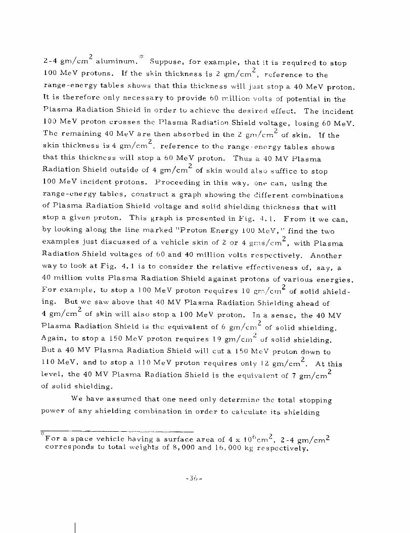
2-4 gm/cm2_ aluminum. :'_ Suppose, for example, that it is required to stop
i00 MeV protons. If the skin thickness is 2 gm/crn 2, reference to the
range-energy tables shows that this thickness will just stop a 40 MeV proton.
It is therefore only necessary to provide 60 million volts of potential in the
Plasma Radiation Shield in order to achieve the desired effect. The incident
100 MeV proton crosses the Plasma Radiation Shield voltage, losing 60 MeV.
The remaining 40 MeV are then absorbed in the 2 gm/cm Z of skin. If the
skin thickness is 4 gm/cm Z, reference to the range-energy tables shows
that this thickness will stop a 60 MeV proton. Thus a 40 MV Plasma
Radiation Shield outside of 4 gm/cm Z of skin would also suffice to stop
100 MeV incident protons. Proceeding in this way, one can, using the
range-energy tables, construct a graph showing the different combinations
of Plasma Radiation Shield voltage and solid shielding thickness that will
stop a given proton. This graph is presented in Fig. 4. I. From it we can,
by looking along the line marked "Proton Energy I00 MeV," find the two2
examples just discussed of a vehicle skin of 9 or 4 gms/cm , with Plasma
Radiation Shield voltages of 60 and 40 million volts respectively. Another
way to look at Fig. 4. l is to consider the relative effectiveness of, say, a
40 million volts Plasma Radiation Shield against protons of various energies.2
For example, to stop a I00 MeV proton requires 10 gm/cm of solid shield-
ing. But we saw above that 40 MV Plasma Radiation Shielding ahead of
4 gm/cm 2 of skin will also stop a I00 MeV proton. In a sense, the 40 MV
Plasma Radiation Shield is the equivalent of 6 gm/cr_ 2 of solid shielding.
Again, to stop a 150 MeV proton requires 19 gm/cm 2 of solid shielding.
But a 40 MV Plasma Radiation Shield will cut a 150 MeV proton down to
ll0 MeV, and to stop a if0 MeV proton requires only [Z gm/cm 2. At this
level, the 40 MV Plasma Radiation Shield is the equivalent of 7 gm/cm 2
of solid shielding.
We have assumed that one need only determine the total stopping
power of any shielding con_bination in order to calculate its shielding
_':_'Fora space vehicle having a surface area of 4 x 106cm 2, 2-4 gm/cm 2
corresponds to total weights of 8,000 and 16,000 kg respectively.
-36-

z
.J¢I
EU
E
z
Jwn
Q
_IO£0
25
2O
15
I0
5
2'5 PROTON ENERGY (MeV)
0 I
0 20 40 60 80 I00 120 140 160 180
PLASMA RADIATION SHIELDING VOLTAGE (MeV)
Fig. 4.1 "Range-Energy Tables" appropriate to a combination of
electrostatic and solid shielding. Following the curves
corresponding to a given proton energy, one may read off
the different proportions of the two shielding components
required to stop the proton. Note the great relative advan-
tage of the first Z0 or 30 MV of electrostatic shielding.
Note also that the graph assumes the electrostatic potential
is outside the solid matter. Reversing the order of the
shields greatly reduces the effectiveness of a given com-
bination.
-37-
A7431

effectiveness. This will, in general, be true where the incident spectrum
is soft, because in this case nearly all the dose delivered at any point is
given (since the spectrum is soft) by those particles _,_hich just arrive.
However, it is not strictly true since different shielding combinations will
differently affect the spectra of protons above the cut off energy. This
effect is exhibited in Fig. 4.2, and in Table 4. I. We consider, for example,
a 60 MV Plasma Radiation Shield ahead of 2 gm/cn_ 2 of aluminum. Both
these shields just stop 100 MeV protons; their different effects on more
energetic protons are listed in Table 4. i. At energies above 100 MeV the
composite shield removes more energy from the incident protons than the
solid shield, but this effect is relatively small for very high energies.
To make these considerations more specific, consider an incident
flux of protons having an integral spectrum in free space given by
ERE F ] n10( > E 0) : IRE F E0 (4. l)
ERE F is any convenient reference energy (in MeV), and IRE F is the inte-Z
grated flux of particles per sq. cm having energies greater than ERE F .
Later on, for a specific case, we shall choose ERE F = i00 MeV, and
IRE F = 108 protons/cm 2, but these choices have no special validity.
The flux of particles in free space having energies between E 0 and
E 0 + dE 0 is
dI 0
dE 0 dEo i
EREF
= n IRE F E0
n+ 1dE 0
EREF(4.2)
Let the Plasma Radiation Shield have a voltage V . There will then be no
flux of particles behind the Plasma Radiation Shield whose energy E 0 in
free space was less than V . The simplest model would be to consider the
flux of particles with energy E I , behind the Plasma Radiation Shield, to
-38-

Incident Energy__..._E0
Plasma Radiation Shield, 60 MV
El I0 gm/cm 2 Aluminum
2gm/cm 2 Aluminum
E2_Energy behind shield _E2
Shield I Shield II
Fig. 4.2 Schematic diagram of two shields each having the abilityto stop i00 MeV protons. Shield I consists of a 60 MVPlasma Radiation Shield ahead of 2 gm/cm 2 of aluminum.Shield II consists of i0 gm/cm 2 of aluminum. The dif-ferent effects that these shields have on protons > I00 MeV,and on the spectra of such protons are discussed in the text.
-39-
A7681

TABLE 4. I
Comparison of Shield Effectiveness
E2
Mev
0
20
50
lO0
150
200
500
lO00
Shield I
E l
Mev
40
47
67
ii0
158
206
5O2
1001
E 0
Mev
100
107
127
170
218
266
562
1061
Shield II
E0
M_v
100
102
115
149
190
232
522
1020
-40-

equal the flux of particles with energy (E l + V) in free space. However,
this approach would yield a finite flux of particles with low energy behind
the Plasma Radiation Shield and does not do justice to the properties of the
electrostatic shield. Particles having an energy just greater than V in
free space will be strongly deflected by the electric field, and can only
penetrate it if their initial motion is accurately parallel to some electric
field line. An estimate of the strength of this effect is that the flux of par-
ticles of energy E0(>V) is reduced by the factor (E 0 V)/E 0 in passing
through the field. This factor is strictly correct for simple geometries and
is probably at least representative for more complicated ones. It has the
right general trend of emphasizing the deflection, or scattering phenomenon
for particles with free space energy IEO just greater than V . When E 0
is much greater than V , the deflection is insignificant, and the factor goes
to unity. Use of this factor yields a differential flux behind the Plasma
Radiation Shield given by:
n+2
dI1 (lE1) [IERIE_F] lEldEldEl = nIRlEF El+V 2die I ERE F
(4.3)
For the present purposes we can roughly simulate the loss of energy
of protons in matter by the equation
die k
dx lE (4.4)
where x is in gm/cm 2. k is a constant, representative of the stopping
material, and having the dimensions (MeV)Zcm2/gm. If the thickness of
the solid shield in the composite arrangement is x I , it will just stop protons
of energy E l = _2kx I . If E i is higher than this, the energy I£2 on
emerging from the solid shield is lE2 : _lE--_ - 2kxI " The total stopping
power of the arrangement is V + _/2kx I . The spectrum of energies
-41 -

emerging from the solid shield is:
dI2(E2)
dE2
dE Z = n IRE F
+ Zkx I + V
n+ 2
E2dE 2
E 2REF
(4.5)
If the thickness of Shield II is Xll gms/cm 2, the differential spectrum
behind it is
n+2
d12(E2) dE2 [" EREF ] E2dE22dE2 = nlREF _E_ + gkXli EREF
(4. 6)
and the shields are comparable if
V + _/2kx I = _ 2kxii (4. 75
f
Choosing for Shield I ___2kx I : 40 MeV and V : 60 MeV , and for
Shield II _2kXli = I00 MeV, the differential spectra (4. 55 and (4.65 are
shown in Fig. 4. 3. We have chosen two values of n , n = 2 (a hard spec-
trum), and n = 4 (a soft spectrum). We have also shown the differential
spectrum (4. Z) in free space. All these spectra are normalized to the
quantity IREF/ERE F , and we have chosen ERE F - I00 MeV, so that
IRE F is the total flux of particles in free space with energies greater than
I00 MeV. We observe that the composite shield passes less flux than the
solid shield at all energies, and that the effect is more pronounced for the
softer flare. This is because the electrostatic scattering factor (E 0 - V)/E 0
is more effective for the softer flare.
These flux calculations can also be converted into dose calculations
if we neglect the variation of the RBE with energy. Using the assumption
-42 -

X
kl.
Z,,Irri,iLLi,
a
I0-I
10-3
10-4I
//
//
//
//
/
''i
FREE SPACE SPECTRA
SOFT
HARD SPI
SOLID SHIELD
SOFT SPECTRUM_HARD SPE
\
//
COMPOSITE SHIELD
SOFT SP
HARD
i I i , I i [
IO IOO
PROTON ENERGY (MeV)
\\\
\\
I000
Fig. 4.3 Differential flux spectra behind the two shields illustrated
in Fig. 4.2. The units of flux are protons/cm2/MeV
divided by the total flux of particles IRFI v above i00 MeV.Two free space spectra are considerea,--5 soft spectrum
having I(>_E2) oc E-4 and a hard spectrum havingI(> E) cc E . Both spectra are assumed to have the sametotal flux above i00 MeV.
-43-
A7454

(4.45 on the rate of energy loss of the protons, the total energy deposition
per unit mass at the back of Shield I (composite5 is just:
oo n+ 2
k _0 [ol EREF ] EREFdE2
n (4. 85D - ERE F IREF 2
WE 2 + 2kx I + V
Doses calculated in this way can be shown to be the point dose at the center
of a sphere of radius x I , and charged to a potential V , provided the flux
in space is isotropic, with intensity I0/4,v per steradian.
The energy deposition per unit mass of equation (4. 8) is (owing to
the units in which k is defined) in units of MeV/gm. However, this is
easily converted, first to ergs/gm, and thence to rads, so that D is a
measure of the radiation dose. To give an idea of the magnitude of the
dimensional factor in Eq. (4.8) we can take ERE F -- 100 MeV, IR_
(which is the number of protons above 100 MeV) = 10 8 protons/cm__an dF k
appropriate to the range of 100 MeV protons in aluminum, i.e., 500 MeV 2
cm2/gm. In this case the dimensional factor kIREF/ERE F is, after
changing units, approximately 8 rads. We introduce the notation
2_-_x I = E (4. 95
so that E is the thickness of the solid shield measured in MeV, we find:
y2+ (E/EREF}2 n+2 (4. 105+ V/ERF F(k IREF/EREF)
Using this formula, we have calculated the dose as a function of
F./ERG F , V/ERE F , and n . ERE F is just an arbitrary normalizing con-
stant, so that the true parameters are E (the equivalent thickness, in
-44-
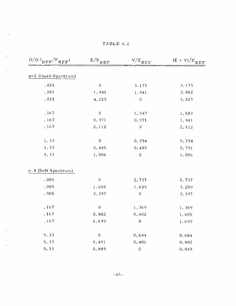
TABLE 4. Z
D/(k IREF/EREF) E/ERE F V/ERE F (E + V)/ERE F
n:2 (Hard Spectrum)
• 021
. 021
.021
0
i. 941
4. 225
3.175
I. 941
0
3. 175
3. 882
4. 225
.167
.167
.167
0
O. 971
2.112
1.587
0.971
0
1.587
1.941
2.112
1.33
1.33
1.33
0
0.485
1.056
0.794
0.485
0
0.794
0.791
1.056
n:4 (Soft Spectrum)
.005
.005
.005
.167
.167
.167
0
I. 605
3. 397
0
0. 802
1.699
2. 737
1.605
0
1. 369
0. 802
0
2. 737
3. 209
3. 397
1.369
1.605
1.699
5.33
5.33
5.33
0
0.401
0.849
0.684
0.401
0
0. 684
0. 802
0. 849
-45-

energy terms, of the solid absorber part of a composite shield), V (thevoltage of the Plasma Radiation Shield part of a composite shield), and
n , the spectrum index. As indicated at the beginning of this section, the
most important parameter of any shield is the energy of the particle it will
just stop. In our case, the composite shield will just stop a proton of
initial energy (]E+ V) MeV. We have therefore shown, in Fig. 4.4, con-
tours of constant dose D (non-dimensionalized as indicated in ]_q. 4.10),
on axes representing the total stopping power of the shield (I_ + V), and the
Plasma Radiation Shield voltage V . On such a graph straight lines can bedrawn to indicate constant values of the ratio of E to V . When E _>V ,
the solid shield is thick and the Plasma Radiation Shield voltage is low, andvice -versa.
As expected, the dose is overwhelmingly a function of E + V , and
only to lesser extent is it affected by the proportions of I_ and V going to
make up E + V . Thus, for the soft spectrum (n = 4) , a factor of 2 change
in E + V yields a factor of 32 change in D . For the hard spectrum (n = 2),
a factor of 2 change in ]_ + V yields a factor of 8 change in D . In spite of
this basic dependence on E + V, however, there is a distinct reduction in
the dose if, at constant E + V , the Plasma Radiation Shield voltage is
raised and the solid shielding thickness reduced. Thus, for the soft spec-
trum at constant ]E + V, the dose for pure Plasma Radiation Shielding is
66% lower than the dose for pure solid shielding. But, since the skin of the
vehicle is not negligible, this is an extreme case. If, instead of going to
pure Plasma Radiation Shielding (E = 0) we go only as far as E = V, the
dose is only 25o/0 below the pure solid (V --0) case -- always at constant
E ÷ V . For the harder spectrum, these percentages are respectively 58%
and 22o/o. But for the harder spectrum, the dose is not quite such a strong
function of (E + V), so that these differences can be more significant. The
differences are chiefly of importance in evaluating the skin dose just behind
the skin of the space vehicle. The dose to organs located deep in the body
is likely to correspond to ]E >>V , so that the total stopping power (E + V)
of the shield is the only parameter of significance. Some of the numbers
calculated from Eq. (4. 10) are listed in Table 4.2.
-46 -

2V
EREF
00
SOFT
- - - HARD
1.33
5.33
I
SPECTRUM( n =4 )SPECTRUM (rl = 2 )
.I
167 \
\
I 2
I
DOSE.021
.005
3
E+V
EREF
E=O
\
\
\\\
\
E=V
E=4V
5
Fig. 4.4 Contours of constant dose behind shields having varying
proportions of Plasma Radiation Shielding (at voltage V)and absorber (measured by the energy E of the proton
which it will just stop). The doses are given in arbitrary
units, which depend on the choice of a reference energy
(ERE F) and a reference integrated flux (IREF_of protons> ERE F . For ERE F - 100 MeV, IRE F = 10 /ca L , theunit of dose is roughly 8rads. The two spectra used have
the same total flux of particles above the energy ERE F .The dose is principally determined by the total stoppingpower {E + V) of the combination, but this is truer for the
soft spectrum than for the hard one. The straight linesrepresent constant proportions of Plasma Radiation Shield-
ing voltage V and absorber thickness E .
-47 -
_,7437

A point of unknown importance is the effect of the Plasma Radiation
Shield on the production of secondary radiations. Although the efficiency
with which energetic protons produce secondaries is a strongly increasing
function of energy, the steep spectra associated with solar flares are thought
to result in the lower energy particles producing the bulk of the secondaries.
If this is true, the Plasma Radiation Shield will exhibit a further advantage,
since the low energy protons will be deflected electrostatically and have no
opportunity to produce secondaries. The relative magnitude of the dose due
to secondaries in solid shields has been estimated 7 at 10% of the direct dose
for thick shields.
Another factor whose importance remains to be evaluated is the effect
on the flux of protons of the magnetic field. There may be a further reduc-
tion of the flux of particles of energy just greater than V due to this effect,
but the magnitude of this reduction wilt depend on the configuration, and is
presently unknown.
In conclusion, we have attempted to bring out the principal factors
governing the choice of Plasma Radiation Shielding voltage. By far the most
important parameter, from the dose point of view, is the total stopping
power (E + V) of the shielding system, including the vehicle skin. Final
selection of the voltage must involve consideration of the total weight of a
shielding system of given (E + V), as E and V vary. It is likely that an
optimum combination will be found, but it is too early to be precise about
its location. In numbers our conclusion from Fig. 4. i is that voltages in
the general range 30-60 MV are likely to be attractive for shielding purposes.
-48 -

5. CONFIGURATION RESTRICTIONS
As previously discussed, conditions on the magnetic fieId dictate
that the shape of a space vehicle that utilizes the Plasma Radiation Shield-
ing concept be a topological torus. However, this requirement is not as
restrictive as one would initially suppose, and we wilt discuss some possible
approaches that may be explored to satisfy this requirement. It should be
borne in mind that the following discussion is intended to be heuristic rather
than definitive, and it is hoped that this brief exposition will stimulate
further ideas in this area.
Shown in Figs. 5. IA to F are some possible spacecraft designs that
would satisfy the configuration requirements. It should be noted that their
common feature is that they all contain a hole someplace. Fig. 5. IA shows
a single element toroidal vehicle that is suitable for a small space station
or interplanetary vehicle. Such a vehicle could have a maximum diameter
of about 33 feet to fit the diameter of a Saturn S-II stage. This type of
vehicle could be made from rigid material, with a minimum number of joints,
and checked out for leaks on the ground. These last considerations are of
particular importance for the Plasma Radiation Shielding concept for, as
will be discussed in Section 7, the need for an extremely tight pressure vessel
favors configurations with a minimum number of joints and a low wall porosity.
The maximum allowable size for the vehicle should not be limited by
the diameter of the launch vehicle. One way of attaining growth potential
while still retaining the basic toroidal shape is to use an inflatable torus that
can be packaged into a small volume and deployed in orbit. Such a device,
however, is probably not too practical as it would lack the requisite structural
strength and rigidity, as well as probably being prone to leakage. A second
way of attaining growth potential that appears more attractive is to use rigid
modules to construct a large vehicle. One such possibility is illustrated in
Fig. 5.1B which shows a larger space vehicle constructed from two rigid
toroidal modules. The modules could be stacked up, for instance, on a
-49-

A SINGLE TORUS
/ \\/
\. /\, /
D "CYLINDRICAL" SPACE VEHICLE
TUNNEL
C TORUS OF CYLINDRICAL MODULES
B TWO TOROIDAL MODULES
\
\.
E SHROUDED COIL
/
F SOLENOID
Fig. 5. I Some possible configurations of spacecraft that utilize the
Plasma Radiation Shield concept. In 'A' is shown the basic
toroidal shape that may be most appropriate for small
vehicles. In 'B' and 'C' are shown growth versions that may
find application for intermediate and very large size vehicles.
Configurations that are not geometrical toruses but which are
acceptable from a topological point of view are shown in 'D'
through 'F' In 'D' is shown a design that utilizes a cylindrical
vehicle with a coil that can be deployed in orbit, while in 'E'
is shown a cylindrical vehicle with a col[ contained in a rigidshroud-like structure. Illustrated in 'F' is a vehicle that
utilizes the solenoid principle discussed in Section 3.6; such
a configuration, if feasible, offers severM potential design
a dvanta g e s.
-50-
A7789

Saturn S-II and assembled in orbit. The docking port and access tunnels
could be of conventional construction, and detached from the systems when
the Plasma Radiation Shield is activated. This configuration has the same
advantages as the single module shown in Fig. 5. IA, with the additional
advantage of a redundant shelter for crew safety in the event of a failure in
one of the modules. If it is desired to use the system for a high altitude,
earth-orbiting station, this configuration would provide some gravity gradient
stabilization.
Another version of the multi-module approach is shown in Fig. 5. IC
which shows several cylindrical elements joined together to form a six-
sided torus. The cylindrical elements could be launch vehicle upper stages,
and this configuration could serve as a very large space station. It may be
noted that the vehicle in Fig. 5.1C is not too different from several designs
that have previously been suggested, with the exception that the latter have
generally included a central docking hub and access spokes to the toroid.
However, because of the requirement that no magnetic field lines intersect
the vehicle, such a variant is unacceptable here. The vehicle shown in
Fig. 5.1C has the ability to provide a measure of artificial gravity for the
crew by rotation about its axis.
There are also allowable spacecraft configurations that do not look
like conventional toruses but still meet the requirements imposed by the
Plasma Radiation Shielding concept. Three of these are shown in Figs. 5. ID
to F. In Fig. 5. ID is shown a cylindrical type spacecraft with a field coil
deployed from it. Such a coil could be deployed in orbit from a vehicle that
may be similar to proposed MOL or Apollo Applications-type vehicles. Such
an approach, however, presents several difficult problems in storing and
erecting the coil in space, as well as in adequately supporting it once it is
erected. This concept also does not make the most effective use of the
field. The vehicle shown in Fig. 5. IE is a variation of that shown in Fig.
5. iD, with a shrouded coil replacing the deployable coil. This design elimi-
nates the coil storage and deployment problems, and provides better support
for the coil.
An interesting possibility is illustrated in Fig. 5. IF where the
vehicle has many of the characteristics of a solenoid. (See also Fig. 3.4.)
-51-

The feature of this design is that the preponderance of electrons are con-
centrated in a relatively small hole through the center of the vehicle.
Because of the low density of electrons along the field lines exterior to the
vehicle, the outer surface may have less stringent requirements for leak
prevention and protuberance control. Thus, as shown in Fig. 5. iF, the
outer surface could contain solar panels, antennas, hatches, docking ports,telescopes, etc., and be of more conventional construction. The inner sur-
face, however, would still require careful control of its leakage charac-
teristics and surface smoothness. Although this approach has many attrac-
tive features, it should be emphasized that it is speculative, being dependenton the unproven assumption of electron concentration in the hole.
It has been mentioned above that the outer surfaces of the vehicles
(with the possible exception of that shown in Fig. 5. IF) should be relatively
smooth and free of protuberances. Just what constitutes an acceptable
degree of smoothness requires further study, and this criteria might well
strongly influence vehicle design and construction. Also influencing the
configuration is the requirement for a structure to resist the magnetic fieldforces (a topic that will be discussed in Section 6).
-52-

6. SUPERCONDUCTING COIL SYSTEM
It is clear that our whole concept depends on the hope that large
scale superconducting coils can be operated in space. It is easily demon-
strated that the power requirements of any room temperature or cryogenic
(not superconducting) electromagnet would be prohibitive for our appli-
cation. Superconductors, however, have the property of dissipating no
heat at all through resistive losses but they must be maintained at very
low temperatures. To achieve very high magnetic fields, it is desirable
to work at 4.2°K (boiling point of liquid helium}. But the Plasma Radiation
Shield may be operated with relatively small fields over relatively large
volumes. In this case it might be adequate to operate around 13°K _:'_and
use liquid hydrogen. It is quite possible that a space vehicle would have a
liquid hydrogen system in connection with its propulsion. Thus this possi-
bility may be quite attractive.
In the absence of ohmic dissipation in the field coils, the only
requirement for power arises from the necessity of removing the heat that
leaks through the thermal insulation. These powers are generally low, but
since heat must be removed at very low temperatures and rejected at
almost room temperature, refrigeration efficiencies are low. Notice,
however, that the Carnot efficiency of a refrigerating cycle operating
between I3°K and room temperature is three times greater than the
efficiency of a cycle operating from 4.2°K.
The current that must be carried by the coil is proportional to the
required level of the magnetic field B , times a characteristic radius R
of the magnet. From Eq. (3. 3. I) the magnetic field intensity B is pro-
portional to E/_ But the voltage V of the Plasma Radiation Shield is
a more basic parameter than the level of the electric field, and scales as
For example, Niobium-Tin has a critical temperature of over 18°K.
-53-

ER . Thus
BR ER VI oc oc oc (6. I)
_0 aoPC Ho_C
and in a first approximation the current is independent of the size of the
vehicle, although there is a dependence on the shape which it is not yet
possible to calculate with much precision. For V = 50 x I06 volts and
p = I/2 , Eq. (6.1) yields a current of 3 x 10⁵ amperes, but the actual cur-
rent required might be several times this value. In particular, the attain-
able value of _ is quite uncertain. In the rest of this section we shall use
a total current of 3 x I06 ampere turns as a typical value, allowing a factor
of I0 for the various uncertainties in F q. (6. I).
Present-day superconductors are characterized by maximum current
densities of about I04 amp/cm 2, but this figure has been increasing as a
result of technical progress. If it is assumed that by the time the Plasma
Radiation Shield is built current densities of the order of 105 amp/cm 2 will
be available, then the cross-sectional area of superconductor required,
2 06 2A , will be 10-5Icm . If I = 3 x i amps, A = 30 cm TheS.C. S.C.
associated mass of superconductor, M , is thenSoC,
M = 2=RD A (6.2)S.C. S.C. S.C.
Ps.c. is the density of the superconducting materiaL, and may be taken as
10 gms/cm 3 The value of R depends on the coil configuration but will
probably be in the neighborhood of 5 meters. Thus M _ 930 kg.,S.C.
subject to the uncertainty in I . The characteristic magnetic fields are
several thousands of gauss.
The weight of the cryogenic system (insulation, refrigeration
machinery, power supply and waste heat radiator) is directly proportional
to the coil surface area, and inversely proportional to the absolute
-54-

operating temperature. For a single turn coil (Fig. 3. 2), the area of the
cryogenic surface is
A .7R (I/106)1"2-/2
= m (6.3)cry
106 2For I = 3 x amps, R = 5m. this is 6.6 m , and is less sensitive to
the uncertainty in I than M . The four-coil arrangement of Fig. 3. 3S.C,
having one quarter the current in each of four coils,would have twice the2
cryogenic area, about 13. Z m If the configuration of Fig. 3.4 used a
winding distributed along the length of the solenoid, A might be asZ cry
much as 50 m For a system operating at 4. Z°K, the mass of the cryo-
genic system and the refrigerator power may be estimated from data pre-
sented in Fig. 6. I (based on Ref. 36). From this figure it is seen that ifZ
Acry 50 m , the power required is 42 kw, and the mass of the system
750 kg. The weight of the power supply has been estimated using a figure
of about I0 kg/kw. Operating at 13°K, the same system would require a
power of 8 kw, and would weigh about 250 kg.
The third component in the superconducting magnet system, in
addition to the superconducting coil and the cryogenic components, is the
support structure necessary to contain the energy stored in the coil. The
structural mass is determined by requirements to resist both tangential
(or hoop) and meridional stresses in the torus (Ref. 36). The magnitude of
the characteristic magnetic field has a strong influence on the structural
weight since the weight varies as the square of the field strength. The
stress level in the magnet is approximately equal to the magnetic pressure
B2/2jX 0 . For a magnetic field strength of about 3300 gauss, such as con-
sidered herein, the equivalent magnetic pressure is about 5 psi. Since this
pressure is of the same order of magnitude as the cabin atmosphere
pressure, the required structuraI problems are not contemplated to be
severe. The actual stress pattern in a configuration like that of Fig. 3. 3
would be quite complex and it is difficult to arrive at an accurate estimate
for the structural weight. The structure of the solenoidal field coil
-55 -
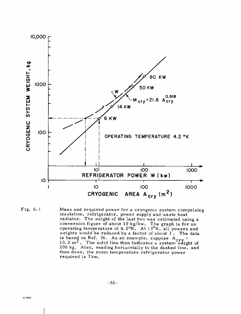
Z
W
W
U)>-U)
L)m
zILl
0>-oc(.)
I0,000
I000
I00
I0
m
m
)
14 KW
80 KW
50 KW
0.918
cry =21-6 Acry
KW
OPERATING TEMPERATURE 4.2 OK
I01 I00
REFRIGERATOR POWER W (kw)I
II000
I 1 I
I0 I00 IO00
CRYOGENIC AREA Acry (m2)
===r
Fig. 6.1 Mass and required power for a cryogenic system comprisinginsulation, refrigerator, power supply and waste heat
radiator. The weight of the last two was estimated using aconversion figure of about 10 kg/kw. The graph is for an
operating temperature of 4.2°K. At 13°K, all powers and
weights would be reduced by a factor of about 3 . The data
is based on Ref. 36. As an example, suppose Act_ =10. Z m 2 . The solid line then indicates a system w_ight of
200 kg. Also, reading horizontally to the dashed line, and
then down, the room temperature refrigerator powerrequired is 7kw.
-56-
A7590

associated with the configuration of Fig. 3.4 would be relatively simple.
Only a small amount of work has been carried out in this area and much
more remains to be done.
One last problem needs to be mentioned in connection with the
design of the magnetic field. In general, one would like to design the coils
so that the vast majority of the magnetic flux is where it is needed, that is,
in the electron cloud and hence outside the space vehicle. In general,
however, any particular coil design will have a certain level for the stray
fields inside the space vehicle. These stray fields must be kept at low
levels if they are not to interfere with the function of equipment sensitive
to magnetic fields within the space vehicle; such things as cathode ray
tubes, magnetic tape recorders and ferrites come to mind. The need to
keep stray fields low would tend to produce a diffused coil design, such as
the four-coil scheme shown in Fig. 3. 3 or the solenoid of Fig. 3.4. Such
designs, however, would entail a penalty in surface area (and hence
refrigeration).
-57-

PRECEDING PAGE BLANK NOT FILMED.
7. VACUUM REQUIREMENTS
It was pointed out in Section 3 that the ionization of neutral atoms
by the electron cloud can constitute a serious source of loss; control of
this source of loss requires that the outward flow of neutral gas originating
in the space vehicle must be held to extremely low levels. The two primary
sources of such gas are: l) Outgassing from the outer surface of the space
vehicle, and 2) Leaks from the interior. In this section we discuss first
the factors determining allowable loss rates, and second, the effect of these
rates on the design of the Plasma Radiation Shield.
7. I Factors Controlling Allowable Leak Rates
In Section 3 we made a preliminary estimate of the allowable leak
rate, but this was based on the most pessimistic assumption, namely, that
each neutral emitted by the space vehicle was ionized right at the wall.
When this happens, the ion thus formed carries away an energy corres-
ponding to the full voltage of the Plasma Radiation Shield. On the other
hand, our estimate of the mean free time of the neutral before ionization
was i second; in this time the neutral is capable of crossing the electron
cloud many times. For example, let the speed of the neutral be 105cm/sec
3and let the size of the electron cloud be 10 cm. In this case, the mean
potential at ionization will be on the order of I% of the full potential; this
results in a vacuum requirement 100 times less stringent than the most
pessimistic case discussed above. To resolve the uncertainties arising in
this way, it is necessary to take account of a number of factors. These
factors are listed below, but, except for the last one (influence of the over-
all geometry), it is felt that the individual uncertainties are not very large.
Later on, in the interest of offering definite numbers, we shall guess that
the combined effect of all the factors does not amount to more than an
order of magnitude, but additional work is required to justify this guess.
The factors are:
-59-

i. The actual velocity of the neutrals. Here it is reasonable to
assume that the neutrals leave the surface of the space vehicle with a
Maxwellian distribution of velocities corresponding to the temperature ofthe surface. If the temperature of the surface is 15°C - Z88°K, the mean
value of the velocity component normal to the surface for some typicalgases is:
H 1.2 x 105cm/s
H2 . 87 x 105
He .60 x 105
N . 32 x 105
N2 .23 x 105
0 .3 x 105
50 2 .21 x i0
ec
Z. The spatial distribution of the electrons. The mean free time
of i sec quoted above was a very rough average. In order to calculate this
time correctly, we require (among other things) to know whether the elec-
trons are in a dense layer near the space vehicle, or spread out over a
considerable distance. The ratio of the size of the electron cloud x to the
mean free path of the neutrals is roughly xnOVe/V n where the symbols
stand for the size of the electron cloud, the electron number density, the
ionization cross section, the electron velocity, and the neutral velocity.
But xn is roughly proportional to the electric field at the wall of thee
vehicle, and this in turn is roughly proportional to _0/x , where 60 is
the potential of the Plasma Radiation Shield. For a given potential, the
ratio in question is smaller when x is relatively large. A more important
ratio is that of the mean potential at ionization to the potential _0 "
However, to a first approximation, this ratio is similar to the ratio of
lengths calculated above.
3. The distribution of electron velocities. This quantity has an
important effect on the product ov which occurs in these calculations.e
-60-
For electrons having kinetic energies significantly large compared to the
ionization energy, the product _v varies roughly ase
_Ve
1 21
mv eoc In
v I ele
where I is an appropriate ionization energy. In general, the electron
energies will be well above the ionization energy so that
l(YV OC
e ve
roughly. Hotter electrons are therefore less efficient producers of
ionization, and hence more desirable from our point of view. To a first
approximation, the electron velocity is simply E/B , but superposed on
this drift motion there is likely to be a "thermal" distribution at an unknown
temperature. This thermal component is likely to be especially important
near the outer edge of the electron cloud, where ]E/B is low. However,
the effect of ionizations which occur near the outer edge is also low.
Its magnitude is at present quite uncertain; this lack of knowledge may
eventually require experimental study.
4. The species of neutral. This not only affects the expected
neutral velocity, but also the ionization cross-section through the quantity
I occurring in the above formula. In general, the heavier gases not only
move more slowly through the electron cloud, but also have larger ioniza-
tion cross-sections. However, it is easier to control the leakage of the
heavier gases.
5. The overall geometry. The electric and magnetic field, the
potential and the electron density have characteristic values, but can also
vary quite widely as a function of position around the space vehicle. For
-61-

example, the electric field and the number density on the outside of the
Plasma Radiation Shield {facing away from the axis) are substantially lower
than those on the inside (facing towards the axis). The extreme possibility
here is the solenoidal configuration of Fig. 3.4. If, as we hope, it turns
out that the electron cloud is entirely confined to the region inside thesolenoid, the whole vacuum problem becomes very much easier. For leaks
from those parts of the surface not facing the electron cloud (i.e., the
outer surface) are of no consequence, and we only have to restrict leakage
from the inside of the solenoid. Thus, one would place all access doors,
antennas and other protuberances on the outside. As stated in Section 3.6,
the existence of this type of confined electron cloud has not yet been demon-strated.
The factors discussed above are not likely to achieve substantially
better definition in the immediate future. It is therefore appropriate, inthe spirit of this paper, to consider the effects of our rough estimates of
allowable leak rates on the design of the Plasma Radiation Shield.The allowable leak rates were estimated in Section 3, on the basis
-6 -4of two different assumptions, as the equivalent of I0 and i0 gins of
oxygen in two days. Except for the configuration of Fig. 3.4, it is probably
not reasonable to imagine that more than a further factor of I0 could comeout of detailed consideration of the various factors enumerated above. This
-3could give an upper limit to the leak rate of I0 gins in two days. To
appreciate the magnitude of these figures let us compare them with com-
parable figures for past and planned manned vehicles. The Mercury vehiclesexperienced a leak rate of 2. 24 [b/day = I kg/day (of air at 5 psia).67 The
internal volume of the Mercury vehicles was small, about 30 ft3 (.85 m3),
so the leak rate per unit volume was about 7. 5 x 10 -2 Ib/day/ft 3
(1.2 kg/day/m3). It is anticipated that the latter figure for the Apollo
-3vehicles will be improved by an order of magnitude to about 7.5 x I0
ib/day/ft 3 68, 69(. 12 kg/day/m3). However, this vehicle will have a much
larger internal volume so that the leak rate itself will not be an order of
magnitude less than Mercury's. Clearly the Mercury-Apollo type con-
struction would yield leak rates that are many orders of magnitude too
large for the application in mind. However, for these vehicles no
-62 -

particular attempt was made in the design to obtain low leak rates, for the
principal penalty was to carry along a few extra pounds of air. At the veryleast it is obviously unreasonable to contemplate losses on the order of
l kg/day for missions lasting several hundred days. Current thinkingindicates that it is possible to obtain much lower leak rates than those
quoted through careful design and a pre-launch program of leak detection.
7.2 Outgassing
If we suppose that the principal source of neutrals near the space
vehicle is due to outgassing from the walls, then we can estimate an
allowable effective pressure over the walls. The permitted current of
atoms may be in the range 1012 to 1015 atoms/sec. Assuming a surface
area of 3 x 10⁶ 2cm , this gives a mean allowed flux of from 106 to 109
atoms/cm2sec. By way of example, these fluxes correspond to a partial
pressure of oxygen of 10 -15 to 10 -12 mm Hg at 15°C. These levels imply
that it will be necessary to apply very high quality vacuum technology to
the design of the Plasma Radiation Shield. However, there are certain
factors which make the environment in deep space exceptionally suitable
for the application of this technology. There will, for example, be ample
time to clean the surface thoroughly in the hard vacuum of outer space.
This could be accomplished by baking out the entire surface while in space,
to above 400°C. On the basis of present knowledge, these procedures, if
applied in space, should be extremely effective and should indeed result in
outgassing rates of the right order of magnitude. Many metal materials
are compatible with bakeout procedures of this type, and bakeout of the
outer metal wall could be accomplished in earth orbit, before departure for
deep space. It could also be accomplished before the vehicle was manned,
although there need be no requirement for the temperature inside the vehicle
to reach the bakeout temperature. Hydrocarbon or teflon seals cannot be
baked to 400°C, but ceramic seals can. It would be desirable to have more
information on the achievement of very clean, outgassed surfaces in the
space environment, but preliminary ideas suggest that this environment is
uniquely suitable to our purposes.
-63-

7. 3 Leaks from the Interior
At room temperature and pressure, the flux of oxygen through a
small plane hole into a vacuum is roughly I0 gms/cm 2 sec or I. 7 x
106 gm/cm 2 in two days. On this simple-minded basis, it would appear
-12 -9 2necessary to restrict leaks to a total area of i0 to I0 cm , but
several factors render this estimate unreasonably pessimistic. Principally,
leaks generally involve long and narrow paths which offer considerable
resistance to any flow. Possibly more important is the fact that the use of
high quality seals and good high vacuum techniques should result in an
essential elimination of leaks.
In spite of these possibilities it seems that it would be highly
desirable to use a double-walled construction technique for the space
vehicle. The inner wall would contain the atmosphere in which the crew
would live, while the space between the two walls could be evacuated to a
rather low pressure, say between 10 -6 and 10 -9 mm Hg. With pressures
of this order in the space between the two walls, the leak through an aper-
ture in the outer wall would be reduced to 2. 3 x I0-3 gm/cm 2 to 2. 3 x IO-6
gms/cm 2 in a period of two days. Thus, in the best case (allowable loss of
-3 -9i0 gms, and an inter-wall pressure of 10 mm Hg), it would be per-
missible to have holes in the outer vessel amounting to [000 cm2! In the
worst case (allowable loss of 10 -6 gins, and an inter-wall pressure of
-6 -3 2I0 mm Hg), plane holes in the outer vessel should not exceed 10 cm
The comment above on long, narrow leakage paths also applies here.
The double-walled construction suggested above has several very
attractive features:
I. Double-walled construction is highly favored as a protection
against puncture of the pressure vessel by large micrometeorites. In
addition to contributing materially to the stopping power of the wall, the
construction provides some degree of fail-safe protection of the cabin
atmosphere.
2. Pumping in the space between the walls to maintain a low pres-
sure in this region would in any event not be difficult. It is particularly
assisted in the present case by the presence of the cryogenic system
associated with the superconducting coils. This syst_I_ normally comprises
-64-

a liquid nitrogen container surrounding the liquid helium; surfaces at liquid
nitrogen temperatures should effectively trap all the heavy gases leaking
out through the inner wall, and reduce the pressure of all other gases that
might be present.3. Double-walled construction with inter-wall pumping relieves the
problem of leaks to such an extent that the use of standard polymer or teflon
seals should be quite satisfactory for the inner vacuum barrier.
Although any form of high vacuum pump could be used to keep the
pressure low between the walls, a particularly attractive prospect might be
to utilize the existing magnetic field to turn part of the space between the
walls into a sort of Vac-Ion Pump. This would involve maintaining a
moderate electric potential between a cathode and an anode, and using acirculating electron beam to ionize and pump any residual neutrals. A
particularly attractive possibility associated with the configuration of
Fig. 3.4 is that the outer wall need only cover that part of the surface
facing the electron cloud, i.e., the interior. Thus, if the outer wall werenot continued on the outside part of the surface, the infinite pump of outer
space would be available to pump from the inter-wall region on the insidesurface.
7.4 Summary
The Plasma Radiation Shield will require a clean outgassed outer
surface and a double-walled pressure vessel with a pressure of roughly
10 -6 to 10 -9 mm Hg in the space between the walls. The exact require-
ments cannot yet be stated with much precision, but do not appear excess-
ively difficult. The space environment is especially favorable to the
achievement of clean surfaces and high vacuum, and the double-walled
construction has subsidiary advantages. On the other hand, this construction
presents many novel design problems to the space vehicle designer. The
requirements for low permeability walls and ground detection of leaks indi-
cate that a welded, metal construction will be necessary. Such a construction
is rigid and places limitations on packaging within the launch vehicle as well
as on the manner in which the system can grow. It will also require careful
consideration of the placement and design of cutouts in the pressure vessel
-65 -

walls, and in the design and selection of material for the seals around thesecutouts.
In addition to the prevention and careful control of leaks, care must
be exercised in allowing no other type of expirations from the vehicle during
a solar flare. This has ramifications in design of such systems as power
supply, attitude control, propulsion, life support, etc. Such systems should
either be chosen to not have an exhaust or, if they do, to be inoperative
during a solar flare. A possible exception to these considerations is the
configuration of Fig. 3.4.
A preliminary conception of the double-walled construction is shown
in Fig. 7. I.
-66 -

A7647


PRECEDING PAGE BLANK NOT FILMED.
8. OTHER SYSTEMS CONSIDERATIONS
The design of other subsystems that go into the total spacecraft
system will also be influenced by the requirements imposed by the Plasma
Radiation Shield. Several of these systems that are most obviously
influenced will now be discussed, and possible design approaches suggested.
8. I Magnet Charging Power Supply
I V 2The total electric field energy is _ C
capacity of the space vehicle and electron cloud.
where C is the effective
If we guess that C is
10 -9 farads, the stored electric energy at 50 x 106 volts is 1.25 x 10⁶ joules.
The magnetic energy is larger than this by roughly r_-2 , so that if f_ --_I
the magnetic energy is 5 x 10⁶ joules. These total figures are subject to
considerable uncertainty both as regards the capacity and the value of _ .
We shal[ suppose, for purposes of illustration, that the uncertainty is a
6factor of ten, and take a representative magnetic field energy as 50 x I0
joules.
The maximum time allowable to energize these fields is of the order
of the time interval between first detection of the flare and the first arrival
of appreciable particle flux. If this time is taken as I-I/2 hr, the power
that must be supplied during this time is about I0 kw for a 50 MV 50 M
joule system. (This figure is in addition to steady power requirements for
the cryogenic system, and typically about 5 to 10 kw for other spacecraft
needs.) The power source for field energization must be operative during
every major solar flare (maybe ten times during a mission) and must not
(except possibly in the configuration of Fig. 3.4) vent exhaust gases to the
exterior during its operation. The latter requirement rules out several
otherwise likely candidates, and a very large solar cell array is ruled out
because it would cut through magnetic field lines. A class of power sources
that meet these requirements and can be available in the time period of
interest is the fue[ ceil. Two types of fuel ceils may be considered for the
application discussed here -- the hydrogen-oxygen and the lithium-chlorine
-69-

types. The hydrogen-oxygen fuel cell is currently available for powers of
a few kilowatts. These devices give off easily-storable water as a by-
product of the reaction, and operate optimally at a relatively Low tempera-ture (90°C). A 2 kw unit will soon be available that weighs 146 Lbs. 70
If more power is necessary, the power supply should have a lower specificweight. Taking hydrogen and oxygen consumption rates of 0. i and 0. 8
lb/kw-hr, respectively, the weight of the fuel cell reactants for the missionis then
Lb.wf = (0. I + 0.8) kw. hr. x 1.5 hr x 10kw x 10applications = 135 lbs.
Including the tankage, the total weight of the power supply using hydrogen-
oxygen fuel cells should be around 1500 lbs for the 10 kw level, and would
scale roughly as the field energy. Lithium-chlorine fuel cells are still in
development but offer the promise of high power levels for short times at
low weight. Aside from their present unavailability, a disadvantage to this
type of fuel cell is their high operating temperature, 650°C. A reasonable
energy density figure to be expected from these ceils for a L0 kw system
with an operating time of i-I/2 hr is about 200 w-hr/lb. 71,72 Using I0 of
these units for the mission would result in a total power supply system
weight of about
lO,O00w x 1-1/2 hrW =
200 w-hr/ibx I0 applications 750 lbs.
In summary, it appears feasible to use hydrogen-oxygen or lithium-chlorine
fuel ceils for the power supply with system weights of Less than 1500 [bs.
Integration of the magnet charging power supply with the general spacecraft
power system would result in a lower weight assignable directly to the
Plasma Radiation Shield, because the specific weight of such power systems
is smaller for Larger powers.
-70-

8. Z Communications
It is very desirable, if not essential, for the crew to be able to com-
municate with the outside while the Plasma Radiation Shield is in operation.
With the exception of the configuration of Fig. 3.4, this must be accomplished
by transmission through the electron cloud that surrounds the space vehicle,
and without the use of lengthy antennas. To do this in the radio range
requires a frequency above the plasma frequency, v 0 , given by v 0 ---3 I/2
9 x 10 (n e) with w0 expressed in megacycles per second, and n e ,
the electron density, in electrons per cubic centimeter. For n = 2. i x3 e
108 per cm (Section 3.2), the plasma frequency is 130 Mc/s. Thus,
transmissions at higher frequencies (such as commonly-used S-band) would
be possible. Another means of communication that could be considered is
by laser beam, since it is anticipated that this type of communication, with
its promised high data rate, will be available in the time period of interest.
8. 3 Attitude Control and Propulsion
The attitude control and the propulsion systems are constrained not
to have an exhaust while the Plasma Radiation Shield is in operation. If it
is necessary to change vehicle attitude during a solar flare, such a change
could possibly be affected by the use of devices such as momentum wheels.
If chemical or nuclear rockets are used as the main propulsion system on
the space vehicle, it would seem that the probability of having to fire them
during a solar flare would be somewhat small. If, however, the propulsion
unit is a system that depends on attaining a desired impulse by a small
thrust applied over a long time, the system would be required to be shut
down while the Plasma Radiation Shield is in operation.
8.4 Life Support
In regard to the crew and their life support, the ecological system
must be of the closed-cycle type, at least for the duration of the flare.
Although the Plasma Radiation Shield concept requires the magnetic field to
be external to the spacecraft, it is fairly certain that some stray, extraneous
fields are bound to exist within the spacecraft interior. While the level of
these stray fields can be reduced arbitrarily, stringent requirements on the
allowab_e level will cause the magnet weight to rise. It is therefore
-71-

worthwhile to examine the effects of these fields on the crew and on internal
equipment.
Medical evidence has been negative as to the effects of magnetic
fields, at least of the magnitudes anticipated in the spacecraft, on human73
beings. The effects of magnetic field gradients are somewhat more
obscure but it is felt that gradients of the magnitude occurring in the space-
craft will also be safe for humans.
8. 5 Effect of Stray Magnetic Fields on Electronic F, quipment
With respect to the effects of these stray magnetic fields on internal
electronic devices, the situation is not so optimistic° It is anticipated that
field strengths could conceivably be strong enough to require shielding or
careful positioning of devices such as tape recorders and oscilloscopes.
-72 -

9. CONCLUSIONS
We have reviewed in some detail the various features of the Plasma
Radiation Shield concept likely to be important in any systems analysis of a
space vehicle using the Plasma Radiation Shield. In summing up our find-
ings, the point of departure must be the following observation: there still
remains a wide range of opinions on the magnitude of the threat posed by
solar flare protons to astronauts. Our premise is that a substantial prob-
lem exists. Since estimates of the solid shielding required are high, the
possibility of reducing shielding weight by using the Plasma Radiation Shield
is attractive.
Pending the satisfactory resolution of several questions, the possi-
bility of realizing the advantages offered by the Plasma Radiation Shield
must remain in doubt. The outstanding questions fall into two distinct
categories:
I) Questions associated with the fundamentals of the concept itself,
such as the attainability of very high voltages, and the stability of the
electron cloud.
2) Questions associated with the integration of a Plasma Radiation
Shield into a space vehicle. The Plasma Radiation Shield makes demands on
the vehicle design in areas of overall configuration, power supply, and leak
control, to name only the most important.
At this point, it is possible to be guardedly optimistic about the
questions in the first category. No insuperable difficulties have been found,
but affirmative statements cannot be made without further experimental and
theoretical studies. It is particularly important to establish the maximum
permissible value of _ = E/cB , since this parameter determines the
strength of the magnetic field and hence the weight of the magnet. In esti-
mating the weight of a Plasma Radiation Shield, the magnet is by far the
most important component.
-73-

As regards the second category of questions, these reduce to defi-
nite quantitative requirements which must be met byanyspace vehicle incor-
porating the Plasma Radiation Shield. The most important questions are
those of overall configuration, and control of leaks.
It was stated in the preface that this paper was regarded as prelimi-
nary to a deeper systems analysis of the Plasma Radiation Shield. It is
therefore appropriate to make some remarks here oi_the basic problems
likely to be encountered in such an analysis. Now a pri11_ary goal of such a
systems analysis will be a reliable graph of weight vs. shielded volume.
This is because unless such a graph can be developed, the advantages of
the Plasma Radiation Shield over solid shielding cann_otbe exhibited in a
quantitative manner. It was explained above that the ,._eight will remain
uncertain until the allowable va[ue of _% can be established. However, it is
also true that the shielded volume of different configurations cannot yet be
given with much accuracy; it is even more true that for a given configuration,
the dimensions cannot be optimized to yield a minimum magnet weight per
unit shielded volume. We are now in a position to calc,llate the shielded
volume for a variety of configurations, but the calculations are difficult
and have not yet been undertaken. Clearly, such calculations must consti-
tute the first step in a detailed systems analysis.
In summary, the Plasma Radiation Shield still appears to offer the
promise of substantial reductions in shielding weight. More work in several
areas will be required in order to show that these reductions can be realized.
-74-

10. ACKNOWLEDGMENTS
It is a pleasure to acknowledge the assistance of G. S. Janes and
J. D. Daugherty in connection with several parts of this paper. We are
indebted to Dr. John C. Helmer of Varian Associates, Palo Alto, California
for permission to use Figs. A. I and A.2, and to Mr. A. Reetz of NASA,
Washington, Do C. for supplying the figures appearing in Table 2. I.
-75 -


PRECEDING PAGE BLANK NOT FILM_D_
Appendix
Status of Work on the Electron Cloud
A.I. introduction
The current status of work on the electron cloud is as follows:
I. Theoretical work 47-53 has thus far failed to find any reason why
a stable dynamic equilibrium for the electron cloud should not exist. This
"double negative" statement is the best that can be made, since, in a prob-
lem as complicated as that of the electron cloud, a positive theoretical
proof of stability is virtually impossible. There have, nevertheless,
appeared certain conditions that the electron cloud must satisfy if it is to
be stable. The most important of these are:
a) the number density n of the electrons, and the magnetic
field strength B must satisfy the condition
ne < 1
_0 B2 30
(A. I. l)
b) the inner edge of the electron cloud must be rather close to
the surface of the Plasma Radiation Shield.
2. It has been observed that the electron cloud in the Plasma
Radiation Shield closely resembles the electron cloud in a high vacuum
pump (the Vac-lon Pump). Encouraging conclusions may be drawn from
the apparent stability of the electron cloud in this pump.
3. Several experiments 49' 74 have been performed to study the
electron cloud, although none has been in the geometry of the Plasma
Radiation Shield. One of the objects of these experiments has been the
demonstration of high voltages using the inductive charging system. In an
electron cloud I0 cm. in radius, voltages in excess of 80,000 have been
-77 -
demonstrated; the achievement of higher voltages presently awaits develop-ment of the means to measure them.
A. 2 Theoretical Work
It is a relatively easy matter to find dynamic equilibria for the
electron cloud under the assumption that the motions of the electrons are
adequately represented by the "guiding center" approxirr'ation:
v = E x B//B Z (A.2.1)
In configurations with axial symmetry, both the electric and magnetic field
vectors lie in the meridional plane, so that the velocity vector is in the azi-
muthal direction. Then, if the number density of electrons is independent of
the azimuth (the symmetrical situation) the condition
div j = div n ev (A.2.2)
on the current is trivially satisfied. It is necessary, however, to require
that the electric potential be such that the magnetic field lines are equi-
potentials. This can be done as follows: since div B = 0 we can write (in
r,0 , z coordinates)
B _ 1 3_ B - [ 5_ (A Z. 3)r r -_z z r 3 r "
the surfaces _(r, z) = constant are then the field lines since along such a
surface
O = d_ 3 _ dr + _ dz =-r [B dr- tB dz] (A 2 4)Or 3z z r " "
-78-

B drr
B dzZ
(A.Z.5)
If we then require the potential _(r, z) to have the form
O(r,7) -- (A.a.6)
where F is an arbitrary function, all the necessary conditions are satis-
fied. The number density can be obtained from (A. 2.6) through Poisson's
equation. It is then only necessary to restrict the range of functions F by
the condition that the number density be everywhere positive.
Inasmuch as the equation (A.2. I) is a very good approximation to
the electron dynamics in the Plasma Radiation Shield, it is expected that
equilibria derived by the method just described will be very close to true
equilibria of the whole electron cloud.
Having exhibited the possibility of equilibria, we turn next to the
much more difficult problem of stability. As stated in the introduction,
stability analysis can in general only arrive at negative statements. Thus,
one can prove that such and such a mode is stable, but, in complicated
systems, one can never be sure that all the important modes have in fact
been dealt with. With these reservations, we can make the following general
statements: In general, we expect stability trouble to occur at or near
characteristic frequencies of the medium. For our electron plasma there
are three such frequencies, namely, the electron gyro frequency
_0 = eB/m (A. 2. 7)C
the electron plasma frequency
-79-
.... . (ne2/¢ l/2p 0 m)
(A. 2. 8)
and the frequency with which the electrons circulate ar,_,md the space
vehicle
_0 = E/BR (A. 2.9)
In view of the connection between the electron number density and the elec-
tric field, these frequencies are related by the following approximate for-
mula:
2= _0 _ (A.2. 10)p c
A convenient non-dimensional number is the ratio
2_, n 173
q - P - (A. 2. ll)
_c 2 ¢0B2
In terms of this ratio, our frequencies can be ordered _s follows:
: _ : co q : \'q : 1 (A. 2. 12)I_ 0 p c
Now for the Plasma Radiation Shield q is a small number, on the order of
10 -3 It follows that the frequencies listed in (A.2. 12) are in ascending
order, with a factor _ 30 between each pair.
All these frequencies are high, however, _() being in the range of
3Mc/sec or so. Hence any instability having a growth rate of even a fairly
-80-

small fraction of these frequencies would be disastrous.
Our findings for the three frequency ranges are as follows:
a) The gyro frequency: Here there is apparently always an
instability. However, the growth rate of this instability is on
the order of 0_0 e-2/q . For q = 10 -3 and 000/2= = 3Mc/sec.,
this gives an exponentiating time longer by far than the age of the
universe! This is not a "fairly" small fraction of w 0 and repre-
sents a growth so slow as to be quite unreasonable. This insta-
bility is of interest only for q > 1/30 .
b) The plasma frequency: Analysis in this region is not yet com-
plete, but it appears that there is no important instability here.
c) Thefrequency _0 = °_p_c : The instability that is important in
this range is called the "diocotron instability." It appears, on
the basis of a considerable amount of work, that this instability
can be avoided in the Plasma Radiation Shie[d configuration pro-
vided that there is not too large a gap between the inner edge of
the electron beam and the conducting wall of the Plasma Radiation
Shield.
Thus, the results of our stability analysis, while not conclusive, are
encouraging. We turn next to the empirical and experimental evidence in
favor of the stability of low-q crossed-field electron beams.
A. 3 Empirical Evidence
Two important devices depend upon crossed-field electron beams --
the microwave magnetron and the low density Penning discharge as applied,
say, in the Vac-Ion Pump.54'75These devices are geometrically rather simi-
lar: both have cylindrical anodes and axial magnetic fields. It is a striking
fact that while both devices are thoroughly successful, the magnetron works
because an inherent instability of the electron beam makes it possible to
extract considerable microwave power, while the Vac-lon Pump works
because the beam is extremely stable; this stability results in long contain-
ment times for the electrons which are therefore quite effective at pumping.
It can be shown that the principal difference between these devices are
the value of q . For the magnetron, q is characteristically a few tenths.
-81-

For the Vac-Ion Pump, q is generally _.07 or less. The instability
previous section having a growth rate _0e-2/q is of thedescribed in the
utmost importance for the magnetron and is altogether negligible for the
Vac-Ion Pump. Naturally, at still smaller values of q this instability is"even more negligible." It appears that the Plasma Radiation Shield can
be considered as a scaled-up Vac-Ion Pump. As such, it may be hoped that
it will exhibit the same remarkable degree of stability.
Fig. A. i is a schematic drawing of the Vac-lon Pump, taken froman article byHelmer and Jepsen. 54 Fig. A.2 is characteristic of the cali-
bration curves associated with these pumps. The most striking feature of
Fig. A.2 is the roughly linear relationship existing between the gas pressurein the device and the current drawn. This linear relationship is an indi-
cation that nothing other than classical diffusion of the electrons by collisionswith the neutrals is taking place. Knowing the voltage applied across thedevice and its characteristic size, it is possible to estimate the total num-
ber of electrons contained in it. Then, on dividing by the current, one
obtains an estimate for the containment time. At a pressure 10-6 mm Hg,_his containment time is approximately 10-3 secs. For the Plasma Radiation
Shield, in the vacuum of space, a pressure of i0 -14 mm should lead to the
required containment time of 105 secs, or about a day.
A. 4 Experimental Work
A number of experiments related to the Plasma Radiation Shield have
been carried out. However, none of these has been in the geometrical shape
of the Plasma Radiation Shield, for the following reason: the topology of the
Plasma Radiation Shield (see, for example, Fig. 3. 3) cannot be used in a
simple way in a laboratory experiment, since the supporting strut which
must necessarily be used is certain to interrupt the drift of the electron
cloud.
The first experiments on the containment of electron clouds are
described in Refs. 49 and 74. Here, we shall give a very brief description
of the most recent experiment. This is an "inside out" torus, shown
schematically in Fig. A. 3, and photographically in Fig. A.4. The object
of the experiment is to exhibit the containment of electron plasmas for
-82 -

ANODE
POTENTIAL
RADIALPOTENTIAL
CATHODE
POTENTIAL
CATHODE I
PLATE
CYLINDRICAL
ANODE
CATHODE
PLATE l
I
' I/_t/ANODE
POTENTIAL£ TRAPPED
ELECTRONCLOUD
SPACE CHARGE
ALDEPRESSION
AXIAL
CATHODE
POTENTIAL
J.C. HELMERR.L. JEPSEN
IAL
Fig. A. I Schematic diagram of a Vac-Ion Pump taken from Ref. 54.
The dynamics of the electron cloud in this device are very
similar to the dynamics of the electron cloud in the Plasma
Radiation Shield, since the value of q = COp./C0c2 < 1/30 .The stability of the electron cloud in this device is clearly
implied by the calibration curve shown in Fig. A. 2.
-83-
A5474

i0-3
0
lo-SW
Z
.Ju.
,, io-6
I1.
F--
W= io-7:)U'J
W
0,.
,o-e
159
II
IO_o
.... ] I .:-
I--- !11
__ IIIIIII '" ::-_CCU;AICYcg _ P_E85LSURTE ,ND,CAT,ON OVER TH,S
P THAT OF GOOD ION GAUGESi I fi i i i II i I [ii i i iii i i ili I i
lOOuo lmo lOmo lOOmo lomp.
PUMP CURRENT
!II
IIlI
IlOomps
Fig. A. Z Calibration curve of a Vac-Ion Pump taken from a Varian
catalog (Ref. 75). Note the roughly linear relationship
between the pressure and the output current over a very
wide range of the variables. This linear relationship can
only be the result of classical diffusion of the electrons to
the anode by means of collisions with the neutrals. Other
pumps of this character have operated down to pressures
like I0 -IZ mm Hg. An estimate of the electron confine-
ment time at this pressure is 1000 secs.
-84-
A7676

TOROIDAL VACUUMSYSTEM
FIELD COILS
_'_POTENTIAL
Fig. A. 3 Schematic of toroidal electron plasma experiment.Electrons are introduced into the torus from a filament in
the slot, compressed by a rising magnetic field, and create
a potential depression along the circular axis of the device.
-85-
A5292

Fig. A. 4 Photograph of the apparatus shown in Fig. A. 3. Note themeter rule across the device.
-86-
A5294

short times (_l msec.), and the achievement of high voltages by com-
pressing the electron cloud with a rising magnetic field. Containment
times longer than l msec. cannot be achieved with this apparatus since
a) the magnetic field is aligned by image currents in the aluminum torus;
these currents decay after about l msec., and b) the apparatus cannot
be pumped down below pressures of a few x 10 -8 mm Hg. The residual gas
at this pressure will discharge the electron cloud in approximately l msec.
Electrons are injected into the apparatus from the heated circular
filament shown in Fig. A. 3. The rising magnetic field then carries these
electrons in towards the middle of the device, where they generate a
potential depression or well. The depth of the well is measured by electro-
static probes. When the magnetic field reaches its peak value, it is
" crowbarred," and decays in about I msec.
The experiment has a minor radius of 10 cm and a major radius of
50 cm. Approximately .02 webers of magnetic flux are introduced in a rise
time of about 20_ sec, giving an induced voltage of about l kV. This voltage
appears across the slot where the filament is located. The peak magnetic
field is about 5 k gauss.
An experimental oscillogram is shown in Fig. A. 5, and data from
several runs is plotted in Fig. A.6. Peak well depths in excess of 80,000
volts have been observed, and our ability to generate higher voltages is
limited at present by lack of means to measure them, since the electrostatic
probes cannot be operated much beyond this figure.
The well depth generated appears to scale roughly with the voltage
induced across the gap by the rising magnetic field, the amplification fac-
tor (or gain), being in the range 50-i00.
So far as they go, these experiments may be regarded as satisfactory.
Current work is directed at improving the gain to a number on the order of
several hundred; it is hoped that this can be done through better control of
the details of the injection process. Another objective is the development
of diagnostic techniques capable of recording voltages above 100 kV. When
these techniques become available, it should be possible to operate the
experiment at generally higher levels of power, voltage, etc.
-87 -

P=5x 10⁻⁷
mm/Hg
IOkVCA PAC ITOR
BANKVOLTAGE
FILAMENT BIAS VOLTAGE,2kV/CM
ETIC FIELD,8 Kg/CM
POTENTIAL (PROBE 4) 50kV/CM
RADIAL POTENTIAL (PROBE ,5) 50kV/CM
TIME 20/zSEC/CM
FILAMENT BIAS VOLTAGE,2 kV/CM
MAGNETIC FIELD, SKg/CM
RADIAL POTENTIAL ( PROBE 4) 50kV/CM
RADIAL POTENTIAL ( PROBE 5) 50 kV/CM
Fig. A. 5 Data obtained with the apparatus of Figs. A. 3 and A. 4.Note the favorable effect of biasing the filament in thesecond oscillogram. The peak potential is 80,000 volts,when the magnetic field is about 5 k gauss.
-88-
A7017

200-
150-
I00-
o
n-
I0 t.2
I0
I.4
I I I I
2 4 6 8
I I I I I I I4 6 8 I0 12 14 20
I I I I.6 .8 1.0 1.2 GAP VOLTAGE, kV
Ito MAGNETIC FIELD, kG
CAPACITOR BANK VOLTAGE, kV
Fig. A. 6 Cross plot of data from the apparatus of Figs. A. 3 andA. 4. Note the linear relationship between the depth of the
potential well and the gap voltage.
-89-
A7018

Under consideration is a new experiment designed to extend our
capabilities in the direction of longer containment times. In this area, the
primary requirement is the use of superior vacuum techniques.
A. 5. Summary
Experimental and theoretical work on a wide front has failed to
produce any fundamental obstacle to the realization of the Plasma Radiation
Shield; on the other hand, the highest voltage exhibited falls short of that
required for the Plasma Radiation Shield by a factor of several hundred,
and containment times at these voltages fall short of the Plasma Radiation
Shield requirements by a factor of 108 .
With regard to the absolute voltage level, however, for a given
electron number density this scales with the square of a suitable linear
dimension. As a full scale device would certainly be ten times the size of
the existing experiment, the short fall in voltage level appears quite reason-
able. As regards the containment time, the Vac-lon Pump shows that in
devices of this kind very long containment times are possible, and that
these times depend only on the pressure of the residual gas. Thus, while
further experimental and theoretical work is obviously required, it is
reasonable to interpret optimistically the data obtained so far.
-90-

REFERENCES
•
_o
B
•
So
t
,
So
o
10.
11.
12.
13.
Second Symposium on Protection Against Radiations in Space, NASA
liP-71, Gatlinburg, Tennessee, October 1964.
Burrel[, M. O., Wright, J. J. and Watts, J. W., "A Preliminary
Report on Energetic Space Radiation and Dose Rate Analysis," NASA
Technical Memorandum X-53531, October 31, 1966.
Hi[berg, R. H., "Solar Cosmic Ray Events," BeHcomm, Inc.,
Report No. TR-65-340-I, November I, 1965.
Hilberg, R. H. , "Radiation Shielding Needed for Extended Inter-
planetary Missions -- Case 103-2," Bellcomm, Inc. , August II,1966.
Burrell, M. O., "Space Radiation Doses During Planetary Missions,"
NASA Technical Memorandum X-53190, January 20, 1965.
Anderson, K. A. , "Preliminary Study of Prediction Aspects of Solar
Cosmic Ray Events," NASA TN D-700, April 1961.
French, F. W. and Hansen, K. F. , "Radiation Shielding Requirements
for Manned Satellites," J. Spacecraft and Rockets 2, 931 (1965).
Keller, J. W., "Long-Range NASA Shielding Requirements,"
Symposium on the Protection Against Radiation Hazards in Space,
_atlinburg, Tennessee, l_ovember 1962.
Abel, J., "Radiation Considerations for Lunar Missions," AAS
Preprint 62-37, January 1962.
Bailey, D. K. , "Time Variations of the Energy Spectrum of Solar
Cosmic Rays in Relation to the Radiation Hazard in Space, " J.
Geophys. Res. 67, 391-396 (January 1962).
Ehricke, K. A., "A Study of Early Manned Interplanetary Missions
(Empire Follow-On)," General Dynamics/Astronautics, GD/A-AOK
64 -002, January 1964.
"Manned Mars Exploration in the Unfavorable (1975-1985) Time
Period," Vo[. If, Summary, Douglas Report SM-45576, January 1964.
Sanders, H. C., "The Effects of Man on the Weight of a Manned
Space Vehicle, '_AAS Preprint 62-12, January 1962.
-91 -

14.
15.
16.
17.
18.
21.
22.
23.
24.
25.
26.
27.
"Manned Interplanetary Missions," Lockheed Missiles and SpaceCompany, Vol. I, Summary, 8-32-63-4. January 1964.
Langham, W. H.,Astron. Sci. Rev.
"Some Radiation Problems of Space Conquest, "2, 9 (October-December 1960).
Proceedings of Conference on Radiation Proble_z_s in Manned SpaceFlight, NASA TN D-588, June 1960.
Barnes, T. G., Finkelman, E. M. and Barazotti, A.
Shielding of Lunar Spacecraft," Astron. Sci. Rev. 3,
1961).
L., "Radiation
i I (January-March
Tobias, C. A., "Radiation Hazards in Space Flight," University of
California RAD Laboratory Report UCRL 8115, January 1958.
Schaefer, H. J., "Radiation Danger in Space," Astron. 5, 36 (1960).
Schaefer, H. J. , "Proton Radiation Hazards in Space," Astron. 6,
39 (1961).
Foelsche, T., "Protection Against Solar Flare Protons," 7th Annual
Meeting, American Astronautical Society, Dallas, Texas, January1961.
Babinsky, A. D., De[ Duca, M. G. and Bond, A. F., "The Radiation
Problem in Low Thrust Space Travel," presented at the ARS 14th
Annual Meeting, Washington, D. C., November 16-20, 1959, ARS
Report 989-59.
Robey,
Flares,D. H., "Radiation Shield Requirements for Two Large Solar" Astronautica Acta 6, Z06 (1960).
Barbieri, L. J. and Lampert, S., "The Interdependence of Manned
Spacecraft Design and Radiation Shielding," Aerospace Eng. 20, 14(1961).
Anderson, K. A. and Fichtel, C. E., "Discussions of Solar Proton
Events and Manned Space Flight," NASA TN D-671, March 1961.
Savin, R. C., Deerwester, J. M., and Mascy, A. C., "Sensitivity of
Manned Planetary Spacecraft Design to Radiation Uncertainties, "
J. Spacecraft 4, 249 (1967).
French, F. W., "Radiation Shielding of Manned Mars Vehicles,"
presented at AIAA "Stepping Stones to Mars Meeting" at Baltimore,
Maryland, March 1966.
-92-

28.
29.
30.
31.
3Z.
33.
34.
35.
36.
37.
38.
39.
40.
41.
Saylor, W. P., Winter, D. E., Fiwen, C. J. and Coriker, A.W.,
"Space Radiation Guide," Aerospace Medical Div. Report AMRI.-TDR62-86, p. 25, 1962.
Webber, !47. R., "An Evaluation of the Radiation IIazard Due to
Solar-Particle Events, _'Boeing Company Report D2-90469, December1963.
"Radiation Biology and Space Environmental Parameters in Manned
Spacecraft Design and Operations, '_Aerospace Medicine 36 (February1965).
Private communication, A. Reetz.
Cosmic Rays, Handbuch d. Phys. 46 (1961).
Levy, R. H. , "Radiation Shielding of Space Vehicles by Means of
Superconducting Coils," ARS J. 31, 1568 (1961}.
Brown, G. , "Magnetic Radiation Shielding," Proceedings of the Inter-
national Conference on High Magnetic Fields, M.I.T., November 1961"
also Wiley, 1962, pp. 370-378.
Dow, N. F., "Structural Implications of the Ionizing Radiation in
Space," Proceedings of the Manned Space Stations Symposium, Los
Angeles, California, April, 1960.
Bernert, R. E. and Stekly, Z. J. J., "Magnetic Radiation Shielding
Systems Analysis," Avco Everett Research Eaboratory Report AMP
134, July 1964.
Levy, R. H. , "Prospects of Active Shielding," presented at Symposium
on the Protection Against Radiation Hazards in Space, Gatlinburg,
Tennessee, November 1962.
Tooper, R. F. and Davies, W. O., "Electromagnetic Shielding of
Space Vehicles," IAS Paper No. 62-156, June 1962.
Tooper, R. F., "Electromagnetic Shielding Feasibility Study,"
Armour Research Foundation Technical Documentary Report No.
ASD-TDR-63-194, May 1963.
Kash, S. W., "Magnetic Space Shields," AIAA Paper No. 65-629,
August I965.
Levine, S. H., Bhattacharjie, A. and Lepper, R., "Forbidden
Regions Produced by Two Parallel Dipoles," AIAA J. 4, 654 (1966}.
-93-

42.
43.
44.
45.
46.
47.
48.
49.
50.
51.
52.
53.
54.
Prescott, Urban and Shelton, "The Application of the Liouville
Theorem to Partially Shielded Regions," Paper presented at Second
Symposium on Protection Against Radiation Hazards in Space, Gatlin-burg, Tennessee, October, 1964.
Bhattacharjie, A. and Michael, I., "Mass and Magnetic Dipole
Shielding Against Electrons of the Artificial Radiation Belt, " AIAA J.2, 2198 (1964).
Levy, R. H., Comment on "Mass and Magnetic Dipole Shielding
Against Electrons on the Artificial Radiation Belt," AIAA J. 3, 988(196s).
Felten, J. E. , "Feasibility of Electrostatic Systems for Space
Vehicle Radiation Shielding," J. Astronautical Sci. ii, 16 (1964).
Levy, R. H. and Janes, G. S., "Plasma Radiation Shielding,2, 1835 (1964).
" AIAA J.
Levy, R. H. and Janes, G. S., "Plasma Radiation Shielding,"Space/Aeronautics 45, 106 (1966).
Levy, R. H., "The Diocotron Instability in a Cylindrical Geometry,"Phys. Fluids 8, 1288 (1965).
Levy, R. H., "The Effect of Coherent Radiation on the Stability of a
Crossed-Field Electron Beam," J. Appl. Phys. 37, 119 (1966).
Levy, R. H. and Janes, G. S., "The Electron Plasma: Experiment,
Theory and Applications," AIAA Paper No. 65-538 (1965).
Janes, G. S., "Experiments on Magnetically Produced and Confined
Electron Clouds," Phys. Rev. Letters 15, 135 (1965).
Levy, R. H. and Callen, J° D., "The Diocotron Instability in a Quasi-
Toroidal Geometry," Phys. Fluids 8, 2298 (1965}o
Buneman, O., Levy, R. H. and Linson, L., "The Stability of Crossed-
Field Electron Beams," J. App[. Phys. 37, 3203 (1966).
Helmet, J. C° and Jepsen, R. L.,
Penning Discharge," Proc. IRE 49,
"Electrical Characteristics of a
1920 (1961).
Alexander, W. M., "Cosmic Dust," Science 138, 1098 (1962)./
Alpert, D., Lee, D. A., Lyman, E. M. and Tomaschke, H. _.,
"Initiation of Electrical Breakdown in Ultrahigh Vacuum," J. of
Vacuum Science g_ Technologyl, November/December 1964.
-94-

57.
58.
59.
60.
61.
62
63
64
65
66
67
68
69
70.
71.
Dyke, W. P. and Trolan, J. K., "Field Emission: Large Current
Densities, Space Charge and the Vacuum Arc," Phys. Rev. 89, 799
(i953).
Dyke, W. P., Trolan, J. K., Martin, E. E."The Field Emission Initiated Vacuum Arc.
Initiation," Phys. Rev. 9[, 1043 (1953).
and Barbour, J. P.,
I. Experiments on Arc
Dolan, W. W., Dyke, Wo P. and Trolan, J. K., "The Field Emission
Initiated Vacuum Arc. If. The Resistive[y Heated Emitter," Phys.
Rev. 91, 1054 (1953).
Fowler, R. H. and Nordheim, L. , "Electron Emission in Intense
Electric Fields," Proc. Roy. Soco (London} All9, 173 (1928).
Van Atta, L. C., Van De Graaff, R. J. and Barton, H. A., "A New
Design for a High-Voltage Discharge Tube, '_ Phys. Rev. 43, 158(1933).
Cranberg, L. , "Initiation of Electrical Breakdo\_n in Vacuum,
Appt. Phys. 23, 5[8 (1952).
', _"
Bennett, W. H., "Magnetical[y Self-Focusing Streams," Phys. Rev.
45, S90 (1934).
Boyle, W. S., Kisliuk, P. and Germer, L. H., "Electrical Break-
down in High Vacuum," 3. AppI. Phys. 26, 720 (1955).
Muller, E. W., "Field Ionization and Field Ion Microscopy, '_ Advances
in Electronics and Electron Physics, Vol. XIII (1960).
Rich, M. and Madey, R. , "Range-Energy Tables," University of
California Radiation Laboratory Report No. 2301, March 1954.
"Environmental Control Systerr, s and Selection for Manned Space
Vehicles," ASD-TDR-61-240, Part I, December 1961.
Ein, H. , "Structures and Materials in the Long-Duration Manned
Spacecraft, '_Astron. and Aeron. 4, 37 (March 1966}.
Thomas, R. S., "Choice of an Atmosphere for an Extended Space
Mission," Proceedings of the First Space Vehicle Thermal and
Atmospheric Control Symposium, ASD-TDR-63-260, April 1963,
pp. 735-759.
Hibben, R. D. , "A1lis-Chalmers Pushes Fuel Cell Efforts," Aviat.
Wk. 86, 65 (1967).
"First Quarterly Technical Progress Report, Thermal Battery,
I July - 30 September 1966," Contract AF33(615)-5343, AllisonDivision of General Motors, October 1966.
-95-

72.
73.
74.
75.
Hietbrink, F. H. , Private communication, Allison Division of General
Motors, Indianapolis, Indiana, 1967.
Beischer, D. E., "Human Tolerance to Magnetic Fields,
24-25, 46 -48 (1962).
" Astron. 7,
QuarterlyProgress Report,
and Space Administration,December 1966.
Contract NAS8-20310, NationaIAeronautics
Office of Advanced Research and Technology,
Vac-Ion Pump 140, 270, 500 and I000 L/S Data Study, Varian Vacuum
Division, Palo Alto, California.
-96-