
GPFS: Concepts, Planning, and Installation Guide
144
General Parallel File System Concepts, Planning, and Installation Guide Version 3.1 GA76-0413-00
Transcript of GPFS: Concepts, Planning, and Installation Guide
General Parallel File System
Concepts, Planning, and Installation Guide
Version 3.1
GA76-0413-00
���


General Parallel File System
Concepts, Planning, and Installation Guide
Version 3.1
GA76-0413-00
���
Note:
Before using this information and the product it supports, be sure to read the general information under “Notices” on page
97.
First Edition (April 2006)
This edition applies to version 3 release 1 for the IBM General Parallel File System for Linux Multiplatform licensed
program (number 5724-N94), the IBM General Parallel File System for Linux on POWER licensed program (number
5765-G67), the IBM General Parallel File System for AIX 5L licensed program (number 5765-G66) and to all
subsequent versions until otherwise indicated in new editions.
IBM welcomes your comments. A form for your comments may be provided at the back of this publication, or you
may address your comments to the following:
International Business Machines Corporation
Department 55JA, Mail Station P384
2455 South Road
Poughkeepsie, NY 12601-5400
United States of America
FAX (United States and Canada): 1+845+432-9405
FAX (Other Countries):
Your International Access Code +1+845+432-9405
IBMLink™ (United States customers only): IBMUSM10(MHVRCFS)
Internet e-mail: [email protected]
If you would like a reply, be sure to include your name, address, telephone number, or FAX number.
Make sure to include the following in your comment or note:
v Title and order number of this book
v Page number or topic related to your comment
When you send information to IBM, you grant IBM a nonexclusive right to use or distribute the information in any
way it believes appropriate without incurring any obligation to you.
Permission to copy without fee all or part of these Message Passing Interface Forum documents is granted by the
University of Tennessee:
v MPI: A Message-Passing Interface Standard, Version 1.1 (c) 1993, 1994, 1995 University of Tennessee, Knoxville,
Tennessee.
v MPI-2: Extensions to the Message-Passing Interface (c) 1995, 1996, 1997 University of Tennessee, Knoxville,
Tennessee.
For more information, see: www.mpi-forum.org.
© Copyright International Business Machines Corporation 1998, 2006. All rights reserved.
US Government Users Restricted Rights – Use, duplication or disclosure restricted by GSA ADP Schedule Contract
with IBM Corp.
Contents
Figures . . . . . . . . . . . . . . . . . . . . . . . . . . . . . . . . . . . . vii
Tables . . . . . . . . . . . . . . . . . . . . . . . . . . . . . . . . . . . . . ix
About this book . . . . . . . . . . . . . . . . . . . . . . . . . . . . . . . . . xi
Who should read this book . . . . . . . . . . . . . . . . . . . . . . . . . . . . . xi
Accessibility information . . . . . . . . . . . . . . . . . . . . . . . . . . . . . . xi
How this book is organized . . . . . . . . . . . . . . . . . . . . . . . . . . . . . xi
Conventions used in this book . . . . . . . . . . . . . . . . . . . . . . . . . . . . xii
Prerequisite and related information . . . . . . . . . . . . . . . . . . . . . . . . . . xii
ISO 9000 . . . . . . . . . . . . . . . . . . . . . . . . . . . . . . . . . . . xiii
How to send your comments . . . . . . . . . . . . . . . . . . . . . . . . . . . . xiii
Summary of changes . . . . . . . . . . . . . . . . . . . . . . . . . . . . . . xv
Part 1. Understanding General Parallel File System . . . . . . . . . . . . . . . 1
Chapter 1. Introducing General Parallel File System . . . . . . . . . . . . . . . . . . . 3
The strengths of GPFS . . . . . . . . . . . . . . . . . . . . . . . . . . . . . . . 3
Shared file system access among GPFS clusters . . . . . . . . . . . . . . . . . . . . 3
Improved system performance . . . . . . . . . . . . . . . . . . . . . . . . . . . 4
File consistency . . . . . . . . . . . . . . . . . . . . . . . . . . . . . . . . 5
High recoverability and increased data availability . . . . . . . . . . . . . . . . . . . . 5
Enhanced system flexibility . . . . . . . . . . . . . . . . . . . . . . . . . . . . 5
Simplified storage management . . . . . . . . . . . . . . . . . . . . . . . . . . . 6
Simplified administration . . . . . . . . . . . . . . . . . . . . . . . . . . . . . 6
The basic GPFS structure . . . . . . . . . . . . . . . . . . . . . . . . . . . . . . 7
GPFS administration commands . . . . . . . . . . . . . . . . . . . . . . . . . . 7
The GPFS kernel extension . . . . . . . . . . . . . . . . . . . . . . . . . . . . 7
The GPFS daemon . . . . . . . . . . . . . . . . . . . . . . . . . . . . . . . 7
The GPFS open source portability layer . . . . . . . . . . . . . . . . . . . . . . . . 8
GPFS cluster configurations . . . . . . . . . . . . . . . . . . . . . . . . . . . . . 8
Interoperable cluster requirements . . . . . . . . . . . . . . . . . . . . . . . . . 12
Chapter 2. Planning for GPFS . . . . . . . . . . . . . . . . . . . . . . . . . . . 15
Hardware requirements . . . . . . . . . . . . . . . . . . . . . . . . . . . . . . 15
Software requirements . . . . . . . . . . . . . . . . . . . . . . . . . . . . . . 15
Recoverability considerations . . . . . . . . . . . . . . . . . . . . . . . . . . . . 16
Node failure . . . . . . . . . . . . . . . . . . . . . . . . . . . . . . . . . 16
Network Shared Disk server and disk failure . . . . . . . . . . . . . . . . . . . . . 19
GPFS cluster creation considerations . . . . . . . . . . . . . . . . . . . . . . . . . 21
GPFS node adapter interface names . . . . . . . . . . . . . . . . . . . . . . . . 22
Nodes in your GPFS cluster . . . . . . . . . . . . . . . . . . . . . . . . . . . 22
GPFS cluster configuration servers . . . . . . . . . . . . . . . . . . . . . . . . . 23
Private IP addresses . . . . . . . . . . . . . . . . . . . . . . . . . . . . . . 24
Remote shell command . . . . . . . . . . . . . . . . . . . . . . . . . . . . . 24
Remote file copy command . . . . . . . . . . . . . . . . . . . . . . . . . . . . 24
Cluster name . . . . . . . . . . . . . . . . . . . . . . . . . . . . . . . . . 24
User ID domain for the cluster . . . . . . . . . . . . . . . . . . . . . . . . . . . 24
Starting GPFS automatically . . . . . . . . . . . . . . . . . . . . . . . . . . . 25
Cluster configuration file . . . . . . . . . . . . . . . . . . . . . . . . . . . . . 25
Managing distributed tokens . . . . . . . . . . . . . . . . . . . . . . . . . . . 25
Disk considerations . . . . . . . . . . . . . . . . . . . . . . . . . . . . . . . . 25
© Copyright IBM Corp. 1998, 2006 iii

NSD creation considerations . . . . . . . . . . . . . . . . . . . . . . . . . . . 27
NSD server considerations . . . . . . . . . . . . . . . . . . . . . . . . . . . . 29
File system descriptor quorum . . . . . . . . . . . . . . . . . . . . . . . . . . . 30
File system creation considerations . . . . . . . . . . . . . . . . . . . . . . . . . . 31
Mountpoint directory . . . . . . . . . . . . . . . . . . . . . . . . . . . . . . 32
Device name of the file system . . . . . . . . . . . . . . . . . . . . . . . . . . 33
NFS V4 ’deny-write open lock’ . . . . . . . . . . . . . . . . . . . . . . . . . . . 33
Disks for your file system . . . . . . . . . . . . . . . . . . . . . . . . . . . . 33
Deciding how the file system is mounted . . . . . . . . . . . . . . . . . . . . . . . 33
Block size . . . . . . . . . . . . . . . . . . . . . . . . . . . . . . . . . . 34
atime values . . . . . . . . . . . . . . . . . . . . . . . . . . . . . . . . . 34
mtime values . . . . . . . . . . . . . . . . . . . . . . . . . . . . . . . . . 35
File system authorization . . . . . . . . . . . . . . . . . . . . . . . . . . . . . 35
File system recoverability parameters . . . . . . . . . . . . . . . . . . . . . . . . 35
Number of nodes mounting the file system . . . . . . . . . . . . . . . . . . . . . . 36
Maximum number of files . . . . . . . . . . . . . . . . . . . . . . . . . . . . 36
Assign mount command options . . . . . . . . . . . . . . . . . . . . . . . . . . 37
Automatic quota activation . . . . . . . . . . . . . . . . . . . . . . . . . . . . 37
Migrate file system format to latest level . . . . . . . . . . . . . . . . . . . . . . . 38
Disk usage verification . . . . . . . . . . . . . . . . . . . . . . . . . . . . . 39
Assign a new device name to the file system . . . . . . . . . . . . . . . . . . . . . 39
Enable DMAPI . . . . . . . . . . . . . . . . . . . . . . . . . . . . . . . . 39
A sample file system creation . . . . . . . . . . . . . . . . . . . . . . . . . . . 39
Part 2. Establishing GPFS on your system . . . . . . . . . . . . . . . . . . 41
Chapter 3. Steps to establishing and starting your GPFS cluster . . . . . . . . . . . . . 43
Chapter 4. Installing GPFS on Linux nodes . . . . . . . . . . . . . . . . . . . . . . 45
Files to ease the installation process . . . . . . . . . . . . . . . . . . . . . . . . . 45
Verifying the level of prerequisite software . . . . . . . . . . . . . . . . . . . . . . . 45
Installation procedures . . . . . . . . . . . . . . . . . . . . . . . . . . . . . . 45
Setting the remote command environment . . . . . . . . . . . . . . . . . . . . . . 46
Electronic license agreement . . . . . . . . . . . . . . . . . . . . . . . . . . . 46
Creating the GPFS directory . . . . . . . . . . . . . . . . . . . . . . . . . . . 46
Installing the GPFS man pages . . . . . . . . . . . . . . . . . . . . . . . . . . 47
Installing GPFS over a network . . . . . . . . . . . . . . . . . . . . . . . . . . 47
Verifying the GPFS installation . . . . . . . . . . . . . . . . . . . . . . . . . . 47
Building your GPFS portability layer . . . . . . . . . . . . . . . . . . . . . . . . . . 48
Using the automatic configuration tool to build GPFS portability layer . . . . . . . . . . . . 48
Chapter 5. Installing GPFS on AIX 5L nodes . . . . . . . . . . . . . . . . . . . . . 49
Files to ease the installation process . . . . . . . . . . . . . . . . . . . . . . . . . 49
Verifying the level of prerequisite software . . . . . . . . . . . . . . . . . . . . . . . 49
Installation procedures . . . . . . . . . . . . . . . . . . . . . . . . . . . . . . 49
Electronic license agreement . . . . . . . . . . . . . . . . . . . . . . . . . . . 50
Creating the GPFS directory . . . . . . . . . . . . . . . . . . . . . . . . . . . 50
Creating the GPFS installation table of contents file . . . . . . . . . . . . . . . . . . . 50
Installing the GPFS man pages . . . . . . . . . . . . . . . . . . . . . . . . . . 50
Installing GPFS over a network . . . . . . . . . . . . . . . . . . . . . . . . . . 50
Existing GPFS files . . . . . . . . . . . . . . . . . . . . . . . . . . . . . . . 51
Verifying the GPFS installation . . . . . . . . . . . . . . . . . . . . . . . . . . 51
Installing Tivoli SANergy and configuring SANergy file systems . . . . . . . . . . . . . . . . 51
Chapter 6. Migration, coexistence and compatibility . . . . . . . . . . . . . . . . . . 53
Migrating to GPFS 3.1 from GPFS 2.3 . . . . . . . . . . . . . . . . . . . . . . . . . 53
iv GPFS: Concepts, Planning, and Installation Guide
Migrating to GPFS 3.1 from GPFS 2.2 or earlier releases of GPFS . . . . . . . . . . . . . . 53
Completing the migration to a new level of GPFS . . . . . . . . . . . . . . . . . . . . 56
Reverting to the previous level of GPFS . . . . . . . . . . . . . . . . . . . . . . . 56
Coexistence . . . . . . . . . . . . . . . . . . . . . . . . . . . . . . . . . . 58
Compatibility . . . . . . . . . . . . . . . . . . . . . . . . . . . . . . . . . . 59
Applying maintenance to your GPFS system . . . . . . . . . . . . . . . . . . . . . . 59
Chapter 7. Configuring and tuning your system for GPFS . . . . . . . . . . . . . . . . 61
General system configuration and tuning considerations . . . . . . . . . . . . . . . . . . 61
Clock synchronization . . . . . . . . . . . . . . . . . . . . . . . . . . . . . . 61
GPFS administration security . . . . . . . . . . . . . . . . . . . . . . . . . . . 61
Cache usage . . . . . . . . . . . . . . . . . . . . . . . . . . . . . . . . . 62
Private IP addresses . . . . . . . . . . . . . . . . . . . . . . . . . . . . . . 63
GPFS I/O . . . . . . . . . . . . . . . . . . . . . . . . . . . . . . . . . . 64
Access patterns . . . . . . . . . . . . . . . . . . . . . . . . . . . . . . . . 64
Aggregate network interfaces . . . . . . . . . . . . . . . . . . . . . . . . . . . 64
Swap space . . . . . . . . . . . . . . . . . . . . . . . . . . . . . . . . . 65
SANergy-controlled file systems . . . . . . . . . . . . . . . . . . . . . . . . . . 65
Linux configuration and tuning considerations . . . . . . . . . . . . . . . . . . . . . . 65
updatedb considerations . . . . . . . . . . . . . . . . . . . . . . . . . . . . . 65
SUSE LINUX considerations . . . . . . . . . . . . . . . . . . . . . . . . . . . 65
GPFS helper threads . . . . . . . . . . . . . . . . . . . . . . . . . . . . . . 66
Communications I/O . . . . . . . . . . . . . . . . . . . . . . . . . . . . . . 66
Disk I/O . . . . . . . . . . . . . . . . . . . . . . . . . . . . . . . . . . . 66
AIX configuration and tuning considerations . . . . . . . . . . . . . . . . . . . . . . . 67
Communications I/O . . . . . . . . . . . . . . . . . . . . . . . . . . . . . . 67
Disk I/O . . . . . . . . . . . . . . . . . . . . . . . . . . . . . . . . . . . 67
Switch pool . . . . . . . . . . . . . . . . . . . . . . . . . . . . . . . . . . 68
Eserver High Performance Switch . . . . . . . . . . . . . . . . . . . . . . . . . 68
IBM Virtual Shared Disk . . . . . . . . . . . . . . . . . . . . . . . . . . . . . 68
GPFS use with Oracle . . . . . . . . . . . . . . . . . . . . . . . . . . . . . . 69
Chapter 8. Steps to permanently uninstall GPFS . . . . . . . . . . . . . . . . . . . . 71
Appendix A. GPFS architecture . . . . . . . . . . . . . . . . . . . . . . . . . . 73
Special management functions . . . . . . . . . . . . . . . . . . . . . . . . . . . 73
The GPFS configuration manager . . . . . . . . . . . . . . . . . . . . . . . . . 73
The file system manager . . . . . . . . . . . . . . . . . . . . . . . . . . . . . 73
The metanode . . . . . . . . . . . . . . . . . . . . . . . . . . . . . . . . 75
Use of disk storage and file structure within a GPFS file system . . . . . . . . . . . . . . . 75
Metadata . . . . . . . . . . . . . . . . . . . . . . . . . . . . . . . . . . 75
Quota files . . . . . . . . . . . . . . . . . . . . . . . . . . . . . . . . . . 77
GPFS recovery logs . . . . . . . . . . . . . . . . . . . . . . . . . . . . . . 77
User data . . . . . . . . . . . . . . . . . . . . . . . . . . . . . . . . . . 78
GPFS and memory . . . . . . . . . . . . . . . . . . . . . . . . . . . . . . . . 78
Pinned and non-pinned memory . . . . . . . . . . . . . . . . . . . . . . . . . . 78
GPFS and network communication . . . . . . . . . . . . . . . . . . . . . . . . . . 79
GPFS daemon communications . . . . . . . . . . . . . . . . . . . . . . . . . . 79
GPFS administration commands . . . . . . . . . . . . . . . . . . . . . . . . . . 81
Application and user interaction with GPFS . . . . . . . . . . . . . . . . . . . . . . . 81
Operating system commands . . . . . . . . . . . . . . . . . . . . . . . . . . . 81
Operating system calls . . . . . . . . . . . . . . . . . . . . . . . . . . . . . 82
GPFS command processing . . . . . . . . . . . . . . . . . . . . . . . . . . . 85
NSD disk discovery . . . . . . . . . . . . . . . . . . . . . . . . . . . . . . . . 86
Recovery . . . . . . . . . . . . . . . . . . . . . . . . . . . . . . . . . . . 86
Cluster configuration data files . . . . . . . . . . . . . . . . . . . . . . . . . . . . 87
Contents v

GPFS backup data . . . . . . . . . . . . . . . . . . . . . . . . . . . . . . . . 88
Appendix B. IBM Virtual Shared Disk considerations . . . . . . . . . . . . . . . . . . 89
Virtual shared disk server considerations . . . . . . . . . . . . . . . . . . . . . . . . 89
Disk distribution . . . . . . . . . . . . . . . . . . . . . . . . . . . . . . . . 89
Disk connectivity . . . . . . . . . . . . . . . . . . . . . . . . . . . . . . . . 90
Virtual shared disk creation considerations . . . . . . . . . . . . . . . . . . . . . . 90
Virtual shared disk server and disk failure . . . . . . . . . . . . . . . . . . . . . . 93
Appendix C. Considerations for GPFS applications . . . . . . . . . . . . . . . . . . . 95
Exceptions to Open Group technical standards . . . . . . . . . . . . . . . . . . . . . 95
Determining if a file system is controlled by GPFS . . . . . . . . . . . . . . . . . . . . 95
GPFS exceptions and limitations to NFS V4 ACLs . . . . . . . . . . . . . . . . . . . . 96
Notices . . . . . . . . . . . . . . . . . . . . . . . . . . . . . . . . . . . . 97
Trademarks . . . . . . . . . . . . . . . . . . . . . . . . . . . . . . . . . . 98
Glossary . . . . . . . . . . . . . . . . . . . . . . . . . . . . . . . . . . . 101
Bibliography . . . . . . . . . . . . . . . . . . . . . . . . . . . . . . . . . 107
GPFS publications . . . . . . . . . . . . . . . . . . . . . . . . . . . . . . . 107
Eserver Cluster 1600 hardware publications . . . . . . . . . . . . . . . . . . . . . 108
AIX publications . . . . . . . . . . . . . . . . . . . . . . . . . . . . . . . . 108
Tivoli publications . . . . . . . . . . . . . . . . . . . . . . . . . . . . . . . . 108
Storage references . . . . . . . . . . . . . . . . . . . . . . . . . . . . . . . 108
Disaster recovery references . . . . . . . . . . . . . . . . . . . . . . . . . . . . 108
IBM Redbooks . . . . . . . . . . . . . . . . . . . . . . . . . . . . . . . . . 109
White papers . . . . . . . . . . . . . . . . . . . . . . . . . . . . . . . . . 109
Useful Web sites . . . . . . . . . . . . . . . . . . . . . . . . . . . . . . . . 109
Non-IBM publications . . . . . . . . . . . . . . . . . . . . . . . . . . . . . . . 110
Index . . . . . . . . . . . . . . . . . . . . . . . . . . . . . . . . . . . . 111
vi GPFS: Concepts, Planning, and Installation Guide

Figures
1. GPFS utilizes the network shared disk subsystem for global disk naming and access . . . . . . 9
2. A Linux-only cluster with disks that are SAN-attached to all nodes . . . . . . . . . . . . . 9
3. A Linux-only cluster with an NSD server . . . . . . . . . . . . . . . . . . . . . . 10
4. An AIX and Linux cluster with an NSD server . . . . . . . . . . . . . . . . . . . . 10
5. An AIX and Linux cluster providing remote access to disks through the High Performance Switch
(HPS) for the AIX nodes and a LAN connection for the Linux nodes . . . . . . . . . . . . 11
6. An AIX and Linux cluster that provides remote access to disks through primary and backup NSD
servers . . . . . . . . . . . . . . . . . . . . . . . . . . . . . . . . . . 11
7. An AIX cluster with an NSD server . . . . . . . . . . . . . . . . . . . . . . . . 12
8. GPFS clusters providing shared file system access . . . . . . . . . . . . . . . . . . 12
9. GPFS configuration utilizing node quorum . . . . . . . . . . . . . . . . . . . . . 17
10. GPFS configuration utilizing node quorum with tiebreaker disks . . . . . . . . . . . . . . 18
11. RAID/ESS Controller twin-tailed in a SAN configuration . . . . . . . . . . . . . . . . . 19
12. GPFS configuration specifying both primary and backup NSD servers connected to a common
disk controller utilizing RAID5 with four data disks and one parity disk . . . . . . . . . . . 20
13. GPFS utilizes failure groups to minimize the probability of a service disruption due to a single
component failure . . . . . . . . . . . . . . . . . . . . . . . . . . . . . . 20
14. GPFS files have a typical UNIX structure . . . . . . . . . . . . . . . . . . . . . . 76
15. Basic failure groups with servers and disks . . . . . . . . . . . . . . . . . . . . . 91
16. Failure groups with twin-tailed disks . . . . . . . . . . . . . . . . . . . . . . . . 92
17. Primary node serving RAID device . . . . . . . . . . . . . . . . . . . . . . . . 93
18. Backup node serving RAID device . . . . . . . . . . . . . . . . . . . . . . . . 93
19. RAID/ESS Controller multi-tailed to the primary and secondary virtual shared disk servers . . . . 94
20. Concurrent node serving device . . . . . . . . . . . . . . . . . . . . . . . . . 94
© Copyright IBM Corp. 1998, 2006 vii

viii GPFS: Concepts, Planning, and Installation Guide

Tables
1. Typographic conventions . . . . . . . . . . . . . . . . . . . . . . . . . . . . xii
2. GPFS cluster creation options . . . . . . . . . . . . . . . . . . . . . . . . . . 21
3. Disk descriptor usage for the GPFS disk commands . . . . . . . . . . . . . . . . . . 29
4. File system creation options . . . . . . . . . . . . . . . . . . . . . . . . . . . 31
© Copyright IBM Corp. 1998, 2006 ix

x GPFS: Concepts, Planning, and Installation Guide

About this book
The General Parallel File System: Concepts, Planning, and Installation Guide describes:
v The IBM® General Parallel File System for Linux® (GPFS) on Multiplatform licensed program, 5724-N94
v The IBM General Parallel File System for Linux (GPFS) on POWER™ licensed program, 5765-G67
v The IBM General Parallel File System for AIX 5L™ (GPFS) licensed program, 5765-G66
v Introducing GPFS
v Planning concepts for GPFS
v Installing GPFS
v Migration, coexistence and compatibility
v Applying maintenance
v Configuration and tuning
v Steps to uninstall GPFS
Who should read this book
This book is intended for system administrators, analysts, installers, planners, and programmers of GPFS
clusters.
It assumes that you are very experienced with and fully understand the operating systems on which your
cluster is based.
Use this book if you are:
v Planning for GPFS
v Installing GPFS on a supported cluster configuration, consisting of:
– Linux nodes
– AIX 5L nodes
– an interoperable cluster comprised of both operating systems
Accessibility information
Accessibility information for the IBM Eserver pSeries® is available online. Visit the IBM Eserver pSeries
Information Center at publib16.boulder.ibm.com/pseries/en_US/infocenter/base. To view information about
the accessibility features of Eserver pSeries software and the AIX® operating system, click AIX and
pSeries accessibility.
How this book is organized
Part 1, “Understanding General Parallel File System” includes:
v Chapter 1, “Introducing General Parallel File System,” on page 3
v Chapter 2, “Planning for GPFS,” on page 15
Part 2, “Establishing GPFS on your system” includes:
v Chapter 3, “Steps to establishing and starting your GPFS cluster,” on page 43
v Chapter 4, “Installing GPFS on Linux nodes,” on page 45
v Chapter 5, “Installing GPFS on AIX 5L nodes,” on page 49
v Chapter 6, “Migration, coexistence and compatibility,” on page 53
v Chapter 7, “Configuring and tuning your system for GPFS,” on page 61
v Chapter 8, “Steps to permanently uninstall GPFS,” on page 71
© Copyright IBM Corp. 1998, 2006 xi
The Appendixes includes:
v Appendix A, “GPFS architecture,” on page 73
v Appendix B, “IBM Virtual Shared Disk considerations,” on page 89
v Appendix C, “Considerations for GPFS applications,” on page 95
“Notices” on page 97
“Glossary” on page 101
“Bibliography” on page 107
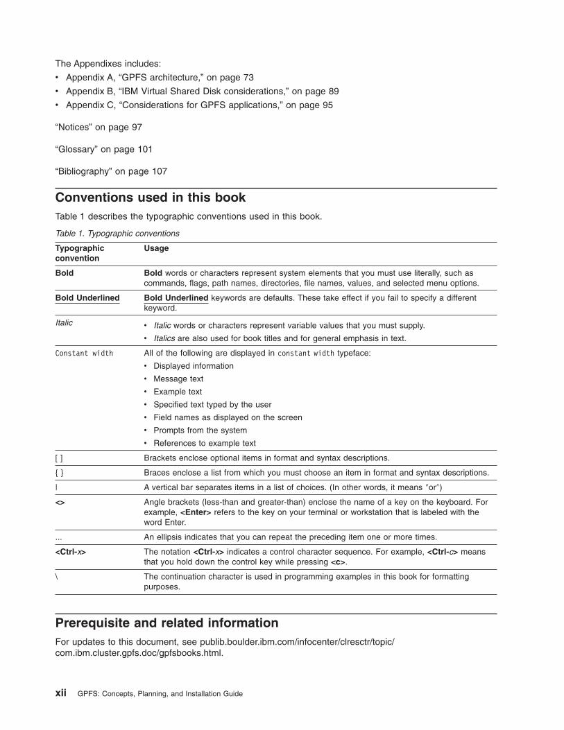
Conventions used in this book
Table 1 describes the typographic conventions used in this book.
Table 1. Typographic conventions
Typographic
convention
Usage
Bold Bold words or characters represent system elements that you must use literally, such as
commands, flags, path names, directories, file names, values, and selected menu options.
Bold Underlined Bold Underlined keywords are defaults. These take effect if you fail to specify a different
keyword.
Italic v Italic words or characters represent variable values that you must supply.
v Italics are also used for book titles and for general emphasis in text.
Constant width All of the following are displayed in constant width typeface:
v Displayed information
v Message text
v Example text
v Specified text typed by the user
v Field names as displayed on the screen
v Prompts from the system
v References to example text
[ ] Brackets enclose optional items in format and syntax descriptions.
{ } Braces enclose a list from which you must choose an item in format and syntax descriptions.
| A vertical bar separates items in a list of choices. (In other words, it means ″or″)
<> Angle brackets (less-than and greater-than) enclose the name of a key on the keyboard. For
example, <Enter> refers to the key on your terminal or workstation that is labeled with the
word Enter.
... An ellipsis indicates that you can repeat the preceding item one or more times.
<Ctrl-x> The notation <Ctrl-x> indicates a control character sequence. For example, <Ctrl-c> means
that you hold down the control key while pressing <c>.
\ The continuation character is used in programming examples in this book for formatting
purposes.
Prerequisite and related information
For updates to this document, see publib.boulder.ibm.com/infocenter/clresctr/topic/com.ibm.cluster.gpfs.doc/gpfsbooks.html.
xii GPFS: Concepts, Planning, and Installation Guide

For the latest support information, see the GPFS Frequently Asked Questions at publib.boulder.ibm.com/infocenter/clresctr/topic/com.ibm.cluster.gpfs.doc/gpfs_faqs/gpfsclustersfaq.html.
ISO 9000
ISO 9000 registered quality systems were used in the development and manufacturing of this product.
How to send your comments
Your feedback is important in helping us to produce accurate, high-quality information. If you have any
comments about this book or any other GPFS documentation:
v Send your comments by e-mail to: [email protected]
Include the book title and order number, and, if applicable, the specific location of the information you
have comments on (for example, a page number or a table number).
v Fill out one of the forms at the back of this book and return it by mail, by fax, or by giving it to an IBM
representative.
To contact the IBM cluster development organization, send your comments by e-mail to:
About this book xiii

xiv GPFS: Concepts, Planning, and Installation Guide
Summary of changes
The following sections summarize changes to the GPFS licensed program and the GPFS library for V3.1
Summary of changes
for GPFS 3.1
as updated, April 2006
Changes to GPFS for this release include:
v New information:
– GPFS now provides for Information Lifecycle Management (ILM) with the introduction of storage
pools, policy-based file management, and filesets.
Storage pools allow you to manage your file system’s storage in groups. You may now partition your
storage based on such factors as performance, locality, and reliability. Files are assigned to a
storage pool based on defined policies.
Policies provide for:
- File placement to a specific storage pool when it is created.
- Migration of a file from one storage pool to another.
- Deletion of a file based on characteristics of the file.
Filesets provide a means of partitioning the namespace of a file system, allowing administrative
operations at a finer granularity than the entire file system:
- You can define per-fileset quotas on data blocks and inodes. These are analogous to existing per
user and per group quotas.
- Filesets can be specified in the policy rules used for placement and migration of file data.
Details on these features are provided in the chapter Policy-based data management for GPFS of
General Parallel File System: Advanced Administration Guide.
New commands in support of storage pools, policies, and filesets include:
- mmapplypolicy
- mmchfileset
- mmchpolicy
- mmcrfileset
- mmdelfileset
- mmlinkfileset
- mmlsfileset
- mmlspolicy
- mmrestripefile
- mmunlinkfileset
New subroutines in support of storage pools and filesets include:
- gpfs_igetstoragepool()
- gpfs_igetfilesetname()
– The requirements for IP connectivity in a multi-cluster environment have been relaxed. In earlier
releases of GPFS, 'all-to-all' connectivity was required. Any node mounting a given file system had to
be able to open a TCP/IP connection to any other node mounting the same file system, irrespective
of which cluster either of the nodes belonged to.
In GPFS 3.1, a node mounting a file system from a remote cluster is only required to be able to
open a TCP/IP connection to nodes in the cluster that owns the file system, but not any other nodes
from other clusters that may be mounting the same file system.
– Enhanced file system mounting supported by three new commands:
© Copyright IBM Corp. 1998, 2006 xv

- The mmmount and mmumount commands are provided for cluster-wide file system
management, alleviating the need for the administrator to issue the dsh command.
- The mmlsmount command displays the IP addresses and names of the nodes (local and remote)
that have a particular file system mounted.
– Enhanced Network Shared Disk functions:
- An option to allow or restrict failover from local to remote access is now provided on the mmchfs,
mmmount, and mmremotefs commands.
In prior releases of GPFS, the only way to failback to local disk access once the connection had
been repaired and access through an NSD server was no longer desired, was to remount the file
system. In this release, GPFS discovers if the path has been repaired. If the path has been
repaired, GPFS falls back to local disk access.
- Improved NSD access information provided by the mmlsnsd command:
v The NSD identifier is now available when specifying the -L option.
v The device type of the disk is now available when specifying the -X option.
– Enhancements to the mmpmon performance monitoring tool:
- Use of a named socket. The mmpmon command no longer uses a network connection for
communication with the GPFS daemon.
- Extends support to include a list of nodes, in the local cluster, to report on instead of just the node
from which the command is issued.
- A new request, source, that specifies an input file for requests.
- A prefix request, once, that directs mmpmon to process a request only once.
– Enhanced mount support for clusters utilizing NSD servers.
You may now specify how long to wait for an NSD server to come online before allowing the mount
to fail. The mmchconfig command has been enhanced allowing to specify wait time when:
- Bringing a cluster online:
v The cluster formation time is at most nsdServerWaitTimeWindowOnMount seconds from the
current time.
v The number of seconds to wait for the server to come up before declaring the mount a failure
as specified by the nsdServerWaitTimeForMount option.
- Bringing an NSD server online when client nodes are already active:
v The last failed time is at most nsdServerWaitTimeWindowOnMount seconds from the current
time.
v The number of seconds to wait for the server to come up before declaring the mount a failure
as specified by the nsdServerWaitTimeForMount option.
– You may now specify different networks for GPFS daemon communication and for GPFS
administration command usage within your cluster. The node descriptor for the mmchcluster
command now allows you to specify separate node interfaces for these uses, for each node within
your cluster. You may choose to use this capability when considering cluster security or performance.
– Improved cluster network access. You may now specify the use of multiple networks for a node in
your cluster allowing both the use of internal networks within a cluster and the use of external
address for remote mounts. The mmchconfig command has been enhanced so that you may
specify a list of individual subnets used to communicate between nodes in a GPFS cluster, ordered
by preference (order in which operands are specified on the subnets option).
– GPFS now provides for the ability to distribute the token management function among multiple nodes
in a cluster, reducing possible bottlenecks. This feature is enabled by default. Nodes that have been
designated as manager nodes are used to distribute the token manager function.
See the General Parallel File System: Concepts, Planning, and Installation Guide for further
information on the roles of the file system manager and the General Parallel File System: Advanced
Administration Guide for details on distributed token managers.
– An autoconfiguration tool is now provided for GPFS for Linux installations.
xvi GPFS: Concepts, Planning, and Installation Guide

GPFS Linux installations require a set of kernel extensions be built to match a customer’s specific
hardware, Linux distribution and kernel . Prior to GPFS V3.1, this was a manual operation (see the
General Parallel File System: Concepts, Planning, and Installation Guide and search on The GPFS
portability layer). In addition to the manual method, there now exists an autoconfiguration tool to
query your system configuration and generate a working configuration file.
– The use of a single port removing conflicts with existing network services.
As of November 2004, port number 1191 was officially registered with InterNet Assigned Numbers
Authority (IANA) for handling GPFS-specific traffic. With this release, all GPFS-related traffic has
been consolidated on port number 1191.
– Improved usability and command consistency by providing the -N flag to indicate which nodes are to
participate in processing the command. Node classes may also be used to specify nodes.
Commands using this new option are:
- mmadddisk
- mmaddnode
- mmchcluster
- mmchconfig
- mmchdisk
- mmcrcluster
- mmdeldisk
- mmdelnsd
- mmdelnode
- mmfsck
- mmgetstate
- mmmount
- mmrestripefs
- mmrpldisk
- mmshutdown
- mmstartup
- mmumount
– The gpfs_getacl() and gpfs_putacl() subroutines have been expanded to allow an externalized
version of the ACL structure to be passed between an application and GPFS.
Please see the GPFS FAQ for information on the latest support for GPFS interoperability.
– The gpfs_quotactl() subroutine has been added to allow manipulating disk quotas on file systems.
v Changed information:
– Improved quorum semantics when utilizing node quorum with tiebreaker disks. The maximum
number of quorum nodes has been increased from two to eight.
– Enhanced quota information in support of filesets.
– Enhancements to the support of NFS V4 on AIX that includes:
- Enhanced ACL behavior:
v UNIX® permissions on an object no longer include a DELETE specification in either the allow
or deny entries.
v DELETE is permitted if the user has either DELETE on the object or DELETE CHILD on the
parent.
– Performance and security enhancements to the mmauth command:
- You may experience performance improvements as GPFS now uses a multithreaded receiver for
authentication, encryption and decryption.
- Multiple security levels, up to one for each authorized cluster, may be specified by the cluster
granting access.
Summary of changes xvii
- The local cluster no longer needs to be shut down prior to changing security keys. This enables
online management of security keys, for example:
v In order to make connection rate performance acceptable in large clusters, the size of the
security keys used for authentication cannot be very large. As a result, it may be necessary to
change security keys in order to prevent a given key from being compromised while it is still in
use.
v As a matter of policy, some institutions may require security keys are changed periodically.
– Enhancement to the mmbackup command to permit specifying a sort directory, using the -s flag.
– Enhancement to the mmlsattr command to display additional file attributes (including the fileset,
storage pool, and snapshot), using the -L flag.
– Enhancement to the mmlsdisk command to display information about how disk I/O requests are
satisfied (locally or using an NSD server), with the -M and -m flags.
– Enhanced error messages reporting in the mmfs log. Messages previously reporting no explanation
now provide the proper text.
– You may experience performance improvements when issuing either the mmlsnsd -M or the
mmlsnsd -m command due to a redesign of the command.
v Deleted information:
– The mmpmon command no longer uses a network connection for communication with the GPFS
daemon.
Summary of changes
for GPFS Version 3.1 library
as updated, April 2006
Changes to the GPFS library for this release include:
v New information:
– The General Parallel File System: Advanced Administration Guide has been introduced. The guide
contains:
- Shared file system access
- Policy-based data management
- Creating and maintaining snapshots
- Disaster recovery
- Monitoring GPFS I/O performance
- Miscellaneous topics, including SANergy®
– For the General Parallel File System: Concepts, Planning, and Installation Guide:
- Information about new configuration and tuning parameters.
– For the General Parallel File System: Administration and Programming Reference:
- New information needed to administer the new GPFS functions listed previously.
- New entries for the commands and subroutines listed previously.
– For the General Parallel File System: Problem Determination Guide:
- New messages for the new functions listed previously.
- New problem determination sections for the new functions listed previously.
– For the General Parallel File System: Data Management API Guide:
- No new information.
v Changed information:
– For the General Parallel File System: Concepts, Planning, and Installation Guide:
- Quorum semantics
- Installation instructions
xviii GPFS: Concepts, Planning, and Installation Guide
- Migration instructions
- Configuration and tuning information
– For the General Parallel File System: Administration and Programming Reference:
- These have been moved to the General Parallel File System: Advanced Administration Guide:
v Shared file system access
v Creating and maintaining snapshots
v Disaster recovery
v Monitoring GPFS I/O performance
v Miscellaneous topics, including SANergy
– For the General Parallel File System: Problem Determination Guide:
Messages and problem determination information for all new and changed GPFS features, as
appropriate.
v Deleted information:
There has been no information deleted from the GPFS library for GPFS V3.1
Summary of changes xix

xx GPFS: Concepts, Planning, and Installation Guide
Part 1. Understanding General Parallel File System
Part 1 provides planning concepts for the General Parallel File System (GPFS) licensed programs:
v Chapter 1, “Introducing General Parallel File System,” on page 3
v Chapter 2, “Planning for GPFS,” on page 15
© Copyright IBM Corp. 1998, 2006 1

2 GPFS: Concepts, Planning, and Installation Guide

Chapter 1. Introducing General Parallel File System
IBM’s General Parallel File System (GPFS) provides file system services to parallel and serial applications.
GPFS allows parallel applications simultaneous access to the same files, or different files, from any node
which has the GPFS file system mounted while managing a high level of control over all file system
operations. GPFS is particularly appropriate in an environment where the aggregate peak need for data
bandwidth exceeds the capability of a distributed file system server.
GPFS allows users shared file access within a single GPFS cluster and across multiple GPFS clusters. A
GPFS cluster consists of:
v AIX 5L nodes, Linux nodes, or a combination thereof (see “GPFS cluster configurations” on page 8). A
node may be:
– An individual operating system image on a single computer within a cluster.
– A system partition containing an operating system. Some System p5™ and pSeries machines allow
multiple system partitions, each of which is considered to be a node within the GPFS cluster.
v Network shared disks (NSDs) created and maintained by the NSD component of GPFS
– All disks utilized by GPFS must first be given a globally accessible NSD name.
– The GPFS NSD component provides a method for cluster-wide disk naming and access.
– On Linux machines running GPFS, you may give an NSD name to:
- Physical disks
- Logical partitions of a disk
- Representations of physical disks (such as LUNs)
– On AIX machines running GPFS, you may give an NSD name to:
- Physical disks
- Virtual shared disks
- Representations of physical disks (such as LUNs)
v A shared network for GPFS communications allowing a single network view of the configuration. A
single network, a LAN or a switch, is used for GPFS communication, including the NSD communication.
The strengths of GPFS
GPFS is a powerful file system offering:
v Shared file system access among GPFS clusters
v Improved system performance
v File consistency
v High recoverability and increased data availability
v Enhanced system flexibility
v “Simplified storage management” on page 6
v Simplified administration
Shared file system access among GPFS clusters
GPFS allows users shared access to files in either the cluster where the file system was created or other
GPFS clusters. Each site in the network is managed as a separate cluster, while allowing shared file
system access. When multiple clusters are configured to access the same GPFS file system, Open Secure
Sockets Layer (OpenSSL) is used to authenticate and check authorization for all network connections.
Note: If you use a cipher, the data will be encrypted for transmissions. However, if you set the cipherlist
keyword of the mmauth command to AUTHONLY, only authentication will be used for data
transmissions and data will not be encrypted.
© Copyright IBM Corp. 1998, 2006 3
GPFS shared file system access provides for:
v The ability of the cluster granting access to specify multiple security levels, up to one for each
authorized cluster.
v A highly available service as the local cluster may remain active prior to changing security keys.
Periodic changing of keys is necessary for a variety of reasons, including:
– In order to make connection rate performance acceptable in large clusters, the size of the security
keys used for authentication can not be very large. As a result it may be necessary to change
security keys in order to prevent a given key from being compromised while it is still in use.
– As a matter of policy, some institutions may require security keys are changed periodically.
Note: The pair of public and private security keys provided by GPFS are similar to host based
authentication mechanism provided by OpenSSH. Each GPFS cluster has a pair of these keys that
identify the cluster. In addition, each cluster also has an authorized_keys list. Each line in the
authorized_keys list contains the public key of one remote cluster and a list of file systems that
cluster is authorized to mount. For details on shared file system access, see the GPFS: Advanced
Administration Guide.
Improved system performance
Using GPFS to store and retrieve your files can improve system performance by:
v Allowing multiple processes or applications on all nodes in the cluster simultaneous access to the same
file using standard file system calls.
v Increasing aggregate bandwidth of your file system by spreading reads and writes across multiple disks.
v Balancing the load evenly across all disks to maximize their combined throughput. One disk is no more
active than another.
v Supporting very large file and file system sizes.
v Allowing concurrent reads and writes from multiple nodes. This is a key concept in parallel processing.
v Allowing for distributed token (lock) management. Distributing token management reduces system
delays associated with a lockable object waiting to obtaining a token. Refer to “Managing distributed
tokens” on page 25 and “High recoverability and increased data availability” on page 5 for additional
information on token management.
v Allowing for the specification of different networks for GPFS daemon communication and for GPFS
administration command usage within your cluster.
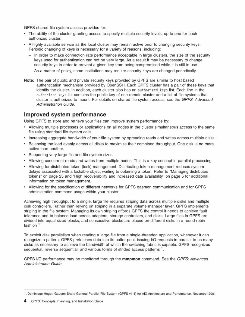
Achieving high throughput to a single, large file requires striping data across multiple disks and multiple
disk controllers. Rather than relying on striping in a separate volume manager layer, GPFS implements
striping in the file system. Managing its own striping affords GPFS the control it needs to achieve fault
tolerance and to balance load across adapters, storage controllers, and disks. Large files in GPFS are
divided into equal sized blocks, and consecutive blocks are placed on different disks in a round-robin
fashion
1
To exploit disk parallelism when reading a large file from a single-threaded application, whenever it can
recognize a pattern, GPFS prefetches data into its buffer pool, issuing I/O requests in parallel to as many
disks as necessary to achieve the bandwidth of which the switching fabric is capable. GPFS recognizes
sequential, reverse sequential, and various forms of strided access patterns
1.
GPFS I/O performance may be monitored through the mmpmon command. See the GPFS: Advanced
Administration Guide.
1. Dominique Heger, Gautam Shah: General Parallel File System (GPFS v1.4) for AIX Architecture and Performance, November 2001
4 GPFS: Concepts, Planning, and Installation Guide
File consistency
GPFS uses a sophisticated token management system to provide data consistency while allowing multiple
independent paths to the same file by the same name from anywhere in the cluster. See “Special
management functions” on page 73.
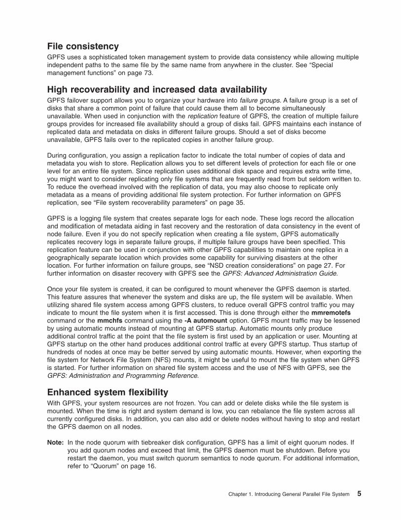
High recoverability and increased data availability
GPFS failover support allows you to organize your hardware into failure groups. A failure group is a set of
disks that share a common point of failure that could cause them all to become simultaneously
unavailable. When used in conjunction with the replication feature of GPFS, the creation of multiple failure
groups provides for increased file availability should a group of disks fail. GPFS maintains each instance of
replicated data and metadata on disks in different failure groups. Should a set of disks become
unavailable, GPFS fails over to the replicated copies in another failure group.
During configuration, you assign a replication factor to indicate the total number of copies of data and
metadata you wish to store. Replication allows you to set different levels of protection for each file or one
level for an entire file system. Since replication uses additional disk space and requires extra write time,
you might want to consider replicating only file systems that are frequently read from but seldom written to.
To reduce the overhead involved with the replication of data, you may also choose to replicate only
metadata as a means of providing additional file system protection. For further information on GPFS
replication, see “File system recoverability parameters” on page 35.
GPFS is a logging file system that creates separate logs for each node. These logs record the allocation
and modification of metadata aiding in fast recovery and the restoration of data consistency in the event of
node failure. Even if you do not specify replication when creating a file system, GPFS automatically
replicates recovery logs in separate failure groups, if multiple failure groups have been specified. This
replication feature can be used in conjunction with other GPFS capabilities to maintain one replica in a
geographically separate location which provides some capability for surviving disasters at the other
location. For further information on failure groups, see “NSD creation considerations” on page 27. For
further information on disaster recovery with GPFS see the GPFS: Advanced Administration Guide.
Once your file system is created, it can be configured to mount whenever the GPFS daemon is started.
This feature assures that whenever the system and disks are up, the file system will be available. When
utilizing shared file system access among GPFS clusters, to reduce overall GPFS control traffic you may
indicate to mount the file system when it is first accessed. This is done through either the mmremotefs
command or the mmchfs command using the -A automount option. GPFS mount traffic may be lessened
by using automatic mounts instead of mounting at GPFS startup. Automatic mounts only produce
additional control traffic at the point that the file system is first used by an application or user. Mounting at
GPFS startup on the other hand produces additional control traffic at every GPFS startup. Thus startup of
hundreds of nodes at once may be better served by using automatic mounts. However, when exporting the
file system for Network File System (NFS) mounts, it might be useful to mount the file system when GPFS
is started. For further information on shared file system access and the use of NFS with GPFS, see the
GPFS: Administration and Programming Reference.
Enhanced system flexibility
With GPFS, your system resources are not frozen. You can add or delete disks while the file system is
mounted. When the time is right and system demand is low, you can rebalance the file system across all
currently configured disks. In addition, you can also add or delete nodes without having to stop and restart
the GPFS daemon on all nodes.
Note: In the node quorum with tiebreaker disk configuration, GPFS has a limit of eight quorum nodes. If
you add quorum nodes and exceed that limit, the GPFS daemon must be shutdown. Before you
restart the daemon, you must switch quorum semantics to node quorum. For additional information,
refer to “Quorum” on page 16.
Chapter 1. Introducing General Parallel File System 5
In a SAN configuration where you have also defined NSD servers, if the physical connection to the disk is
broken, GPFS dynamically switches disk access to the servers nodes and continues to provide data
through NSD server nodes. GPFS falls back to local disk access when it has discovered the path has
been repaired.
After GPFS has been configured for your system, depending on your applications, hardware, and
workload, you can re-configure GPFS to increase throughput. You can set up your GPFS environment for
your current applications and users, secure in the knowledge that you can expand in the future without
jeopardizing your data. GPFS capacity can grow as your hardware expands.
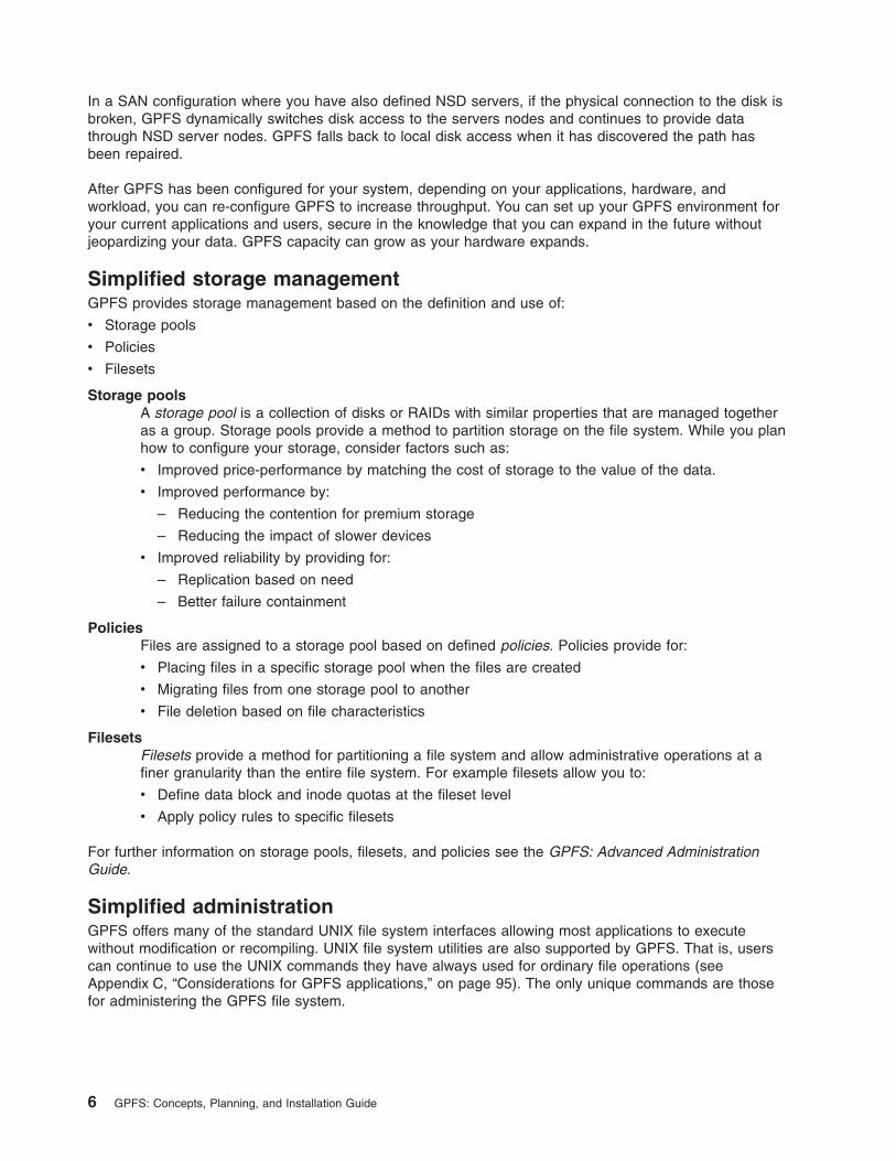
Simplified storage management
GPFS provides storage management based on the definition and use of:
v Storage pools
v Policies
v Filesets
Storage pools
A storage pool is a collection of disks or RAIDs with similar properties that are managed together
as a group. Storage pools provide a method to partition storage on the file system. While you plan
how to configure your storage, consider factors such as:
v Improved price-performance by matching the cost of storage to the value of the data.
v Improved performance by:
– Reducing the contention for premium storage
– Reducing the impact of slower devices
v Improved reliability by providing for:
– Replication based on need
– Better failure containment
Policies
Files are assigned to a storage pool based on defined policies. Policies provide for:
v Placing files in a specific storage pool when the files are created
v Migrating files from one storage pool to another
v File deletion based on file characteristics
Filesets
Filesets provide a method for partitioning a file system and allow administrative operations at a
finer granularity than the entire file system. For example filesets allow you to:
v Define data block and inode quotas at the fileset level
v Apply policy rules to specific filesets
For further information on storage pools, filesets, and policies see the GPFS: Advanced Administration
Guide.
Simplified administration
GPFS offers many of the standard UNIX file system interfaces allowing most applications to execute
without modification or recompiling. UNIX file system utilities are also supported by GPFS. That is, users
can continue to use the UNIX commands they have always used for ordinary file operations (see
Appendix C, “Considerations for GPFS applications,” on page 95). The only unique commands are those
for administering the GPFS file system.
6 GPFS: Concepts, Planning, and Installation Guide

GPFS administration commands are similar in name and function to UNIX file system commands, with one
important difference: the GPFS commands operate on multiple nodes. A single GPFS command performs
a file system function across the entire cluster. See the individual commands as documented in the GPFS:
Administration and Programming Reference.
GPFS commands save configuration and file system information in one or more files, collectively known as
GPFS cluster configuration data files. The GPFS administration commands are designed to keep these
files synchronized between each other and with the GPFS system files on each node in the cluster,
thereby providing for accurate configuration data. See “Cluster configuration data files” on page 87.
The basic GPFS structure
GPFS is a clustered file system defined over a number of nodes. On each node in the cluster, GPFS
consists of:
1. Administration commands
2. A kernel extension
3. A multithreaded daemon
4. For nodes in your cluster operating with the Linux operating system, “The GPFS open source
portability layer” on page 8
For a detailed discussion of GPFS, see Appendix A, “GPFS architecture,” on page 73.
GPFS administration commands
Most GPFS administration tasks can be performed from any node running GPFS. See the individual
commands as documented in the GPFS: Administration and Programming Reference.
The GPFS kernel extension
The GPFS kernel extension provides the interfaces to the operating system vnode and virtual file system
(VFS) interfaces for adding a file system. Structurally, applications make file system calls to the operating
system, which presents them to the GPFS file system kernel extension. In this way, GPFS appears to
applications as just another file system. The GPFS kernel extension will either satisfy these requests using
resources which are already available in the system, or send a message to the GPFS daemon to complete
the request.
The GPFS daemon
The GPFS daemon performs all I/O and buffer management for GPFS. This includes read-ahead for
sequential reads and write-behind for all writes not specified as synchronous. All I/O is protected by GPFS
token management which honors atomicity thereby providing for data consistency of a file system on
multiple nodes.
The daemon is a multithreaded process with some threads dedicated to specific functions. Dedicated
threads for services requiring priority attention are not used for or blocked by routine work. The daemon
also communicates with instances of the daemon on other nodes to coordinate configuration changes,
recovery and parallel updates of the same data structures. Specific functions that execute on the daemon
include:
1. Allocation of disk space to new files and newly extended files. This is done in coordination with the file
system manager.
2. Management of directories including creation of new directories, insertion and removal of entries into
existing directories, and searching of directories that require I/O.
3. Allocation of appropriate locks to protect the integrity of data and metadata. Locks affecting data that
may be accessed from multiple nodes require interaction with the token management function.
4. Disk I/O is initiated on threads of the daemon.
Chapter 1. Introducing General Parallel File System 7

5. User security and quotas are also managed by the daemon in conjunction with the file system
manager.
For further information, see “Special management functions” on page 73.
The GPFS open source portability layer
For Linux nodes running GPFS, you must build custom portability modules based on your particular
hardware platform and Linux distribution to enable communication between the Linux kernel and the GPFS
kernel modules. See “Building your GPFS portability layer” on page 48.
GPFS cluster configurations
GPFS is designed to operate with:
The operating system kernel
Provides the basic operating system services and the routing of file system calls requiring GPFS
data.
Network Shared Disk (NSD)
This GPFS component provides:
v Disk access through disk discovery
The NSDs in your cluster may be physically attached to all nodes or serve their data through a
primary and, if specified, backup NSD server, providing a virtual connection. GPFS determines if
a node has physical or virtual connectivity to an underlying NSD through a sequence of
commands invoked from the GPFS daemon. This determination is called disk discovery and
occurs at both initial GPFS startup as well as whenever a file system is mounted.
The default order of access used in disk discovery:
1. Local /dev block device interfaces for virtual shared disk, SAN, SCSI or IDE disks
2. NSD servers
This order can be changed by use of the useNSDserver mount option.
As GPFS determines the available connections to disks in the file system, it is suggested you
always define NSD servers for the disks. In a SAN configuration where NSD servers have also
been defined, if the physical connection is broken, GPFS dynamically switches to the servers
nodes and continues to provide data. GPFS falls back to local disk access when it has
discovered the path has been repaired. This is the default behavior, and can be changed with
the useNSDserver file system mount option.
v Cluster-wide disk naming
The cluster-wide NSD name uniquely identifies a disk, even when that disk is visible as different
/dev entries on different nodes.
8 GPFS: Concepts, Planning, and Installation Guide

For further information, see “Disk considerations” on page 25 and “NSD disk discovery” on page
86.
GPFS has several cluster configurations. A subset of these configurations includes:
1. Configurations where all disks are SAN-attached to all nodes in the cluster and the nodes in the cluster
are either all Linux or all AIX (refer to Figure 2). For the latest hardware that GPFS has been tested
with, see the GPFS FAQ at publib.boulder.ibm.com/infocenter/clresctr/topic/com.ibm.cluster.gpfs.doc/gpfs_faqs/gpfsclustersfaq.html
2. A Linux-only cluster consisting of xSeries®, System p5, pSeries, or Eserver
™ machines with an NSD
server attached to the disk (refer to Figure 3 on page 10). Nodes not directly attached to the disk have
remote data access over the local area network (either Ethernet or Myrinet) to the NSD server. A
backup NSD server having direct Fibre Channel access to the disks may also be defined. Any nodes
directly attached to the disk will not access data through the NSD server. This is the default behavior
and can be changed with the useNSDserver file system mount option.
Figure 1. GPFS utilizes the network shared disk subsystem for global disk naming and access
Figure 2. A Linux-only cluster with disks that are SAN-attached to all nodes
Chapter 1. Introducing General Parallel File System 9
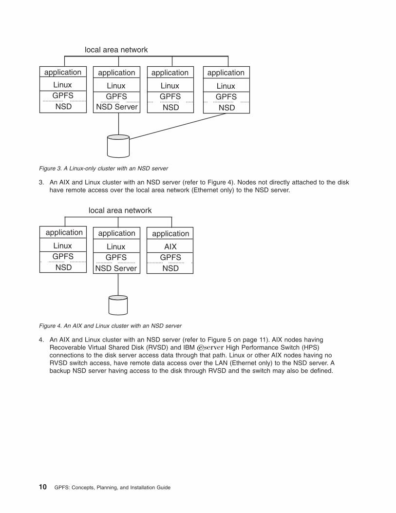
3. An AIX and Linux cluster with an NSD server (refer to Figure 4). Nodes not directly attached to the disk
have remote access over the local area network (Ethernet only) to the NSD server.
4. An AIX and Linux cluster with an NSD server (refer to Figure 5 on page 11). AIX nodes having
Recoverable Virtual Shared Disk (RVSD) and IBM ERserver High Performance Switch (HPS)
connections to the disk server access data through that path. Linux or other AIX nodes having no
RVSD switch access, have remote data access over the LAN (Ethernet only) to the NSD server. A
backup NSD server having access to the disk through RVSD and the switch may also be defined.
Figure 3. A Linux-only cluster with an NSD server
Figure 4. An AIX and Linux cluster with an NSD server
10 GPFS: Concepts, Planning, and Installation Guide
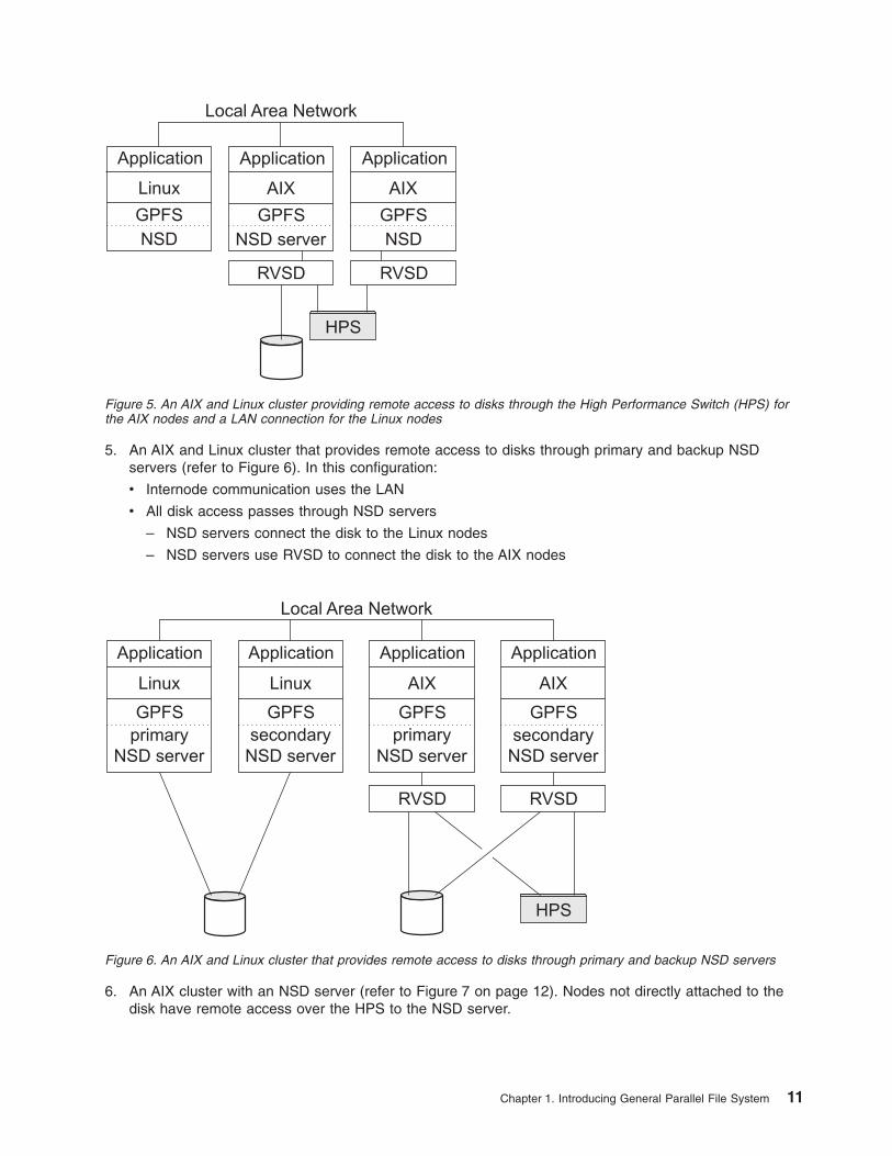
5. An AIX and Linux cluster that provides remote access to disks through primary and backup NSD
servers (refer to Figure 6). In this configuration:
v Internode communication uses the LAN
v All disk access passes through NSD servers
– NSD servers connect the disk to the Linux nodes
– NSD servers use RVSD to connect the disk to the AIX nodes
6. An AIX cluster with an NSD server (refer to Figure 7 on page 12). Nodes not directly attached to the
disk have remote access over the HPS to the NSD server.
HPS
GPFS
NSD
Linux
Application
GPFS
NSD server
AIX
Application
GPFS
NSD
AIX
Application
RVSDRVSD
Local Area Network
Figure 5. An AIX and Linux cluster providing remote access to disks through the High Performance Switch (HPS) for
the AIX nodes and a LAN connection for the Linux nodes
HPS
GPFS
NSD server
Linux
primary
Application
GPFS
NSD server
AIX
secondary
ApplicationApplication
GPFS
NSD server
AIX
primary
GPFS
NSD server
Linux
secondary
Application
RVSD RVSD
Local Area Network
Figure 6. An AIX and Linux cluster that provides remote access to disks through primary and backup NSD servers
Chapter 1. Introducing General Parallel File System 11

7. Shared file system access among multiple GPFS clusters (refer to Figure 8). The GPFS clusters
sharing file system access may be any supported configuration.
For the latest list of supported cluster configurations, please see the GPFS FAQ at publib.boulder.ibm.com/infocenter/clresctr/topic/com.ibm.cluster.gpfs.doc/gpfs_faqs/gpfsclustersfaq.html.
Interoperable cluster requirements
Consult the GPFS FAQ at publib.boulder.ibm.com/infocenter/clresctr/topic/com.ibm.cluster.gpfs.doc/gpfs_faqs/gpfsclustersfaq.html for any changes to requirements and currently tested:
1. Hardware configurations
2. Software configurations
3. Cluster configurations
These software requirements apply to an interoperable GPFS cluster:
v All nodes must have GPFS 3.1 and the latest service level installed.
These configuration requirements apply to an interoperable GPFS cluster:
GPFS
NSD
AIX
Application
GPFS
NSD server
AIX
Application
GPFS
NSD
AIX
Application
High Performance Switch
Figure 7. An AIX cluster with an NSD server
Figure 8. GPFS clusters providing shared file system access
12 GPFS: Concepts, Planning, and Installation Guide

v All file systems defined on versions of GPFS prior to version 2.3 must be exported from their old cluster
definition and re-imported into a newly created 3.1 cluster. Cluster configuration dependencies and
setup changed significantly in GPFS version 2.3. See “Migrating to GPFS 3.1 from GPFS 2.2 or earlier
releases of GPFS” on page 53.
v The NSD primary and backup servers for each disk device must be defined on a homogenous set of
Linux or AIX nodes. They may not be split between operating system types. See Figure 6 on page 11.
v For most disk subsystems, all nodes accessing a SAN-attached disk (LUN) must use the same
operating system. Most disk subsystems do not allow you to have Linux nodes and AIX nodes attached
to the same LUN. Refer to the information supplied with your specific disk subsystem for details about
supported configurations.
Chapter 1. Introducing General Parallel File System 13

14 GPFS: Concepts, Planning, and Installation Guide
Chapter 2. Planning for GPFS
Planning for GPFS includes:
v “Hardware requirements”
v “Software requirements”
v “Recoverability considerations” on page 16
v “GPFS cluster creation considerations” on page 21
v “Disk considerations” on page 25
v “File system creation considerations” on page 31
Although you can modify your GPFS configuration after it has been set, a little consideration before
installation and initial setup will reward you with a more efficient and immediately useful file system. During
configuration, GPFS requires you to specify several operational parameters that reflect your hardware
resources and operating environment. During file system creation, you have the opportunity to specify
parameters based on the expected size of the files or allow the default values to take effect. These
parameters define the disks for the file system and how data will be written to them.
Hardware requirements
1. Please consult the GPFS FAQ at publib.boulder.ibm.com/infocenter/clresctr/topic/com.ibm.cluster.gpfs.doc/gpfs_faqs/gpfsclustersfaq.html for latest list of:
v Supported hardware
v Tested disk configurations
v Maximum cluster size
2. Enough disks to contain the file system. Disks can be:
v SAN-attached to each node in the cluster
v Attached to the primary and, if specified, backup NSD server
v A mixture of direct attached and primary and secondary NSDs
v Refer to “NSD creation considerations” on page 27 for additional information
3. Since GPFS passes a large amount of data between its daemons, it is suggested that you configure a
dedicated high speed network supporting the IP protocol when you are using GPFS:
v With NSD disks configured with servers providing remote disk capability
v Multiple GPFS clusters providing remote mounting of and access to GPFS file systems
v Refer to the GPFS: Advanced Administration Guide for additional information
GPFS communications require invariant static IP addresses for each specific GPFS node. Any IP address
takeover operations which transfer the address to another computer are not allowed for the GPFS
network. Other IP addresses within the same computer which are not used by GPFS can participate in IP
takeover. GPFS can use virtual IP addresses created by aggregating several network adapters using
techniques such as EtherChannel or channel bonding.
Software requirements
Please consult the GPFS FAQ at publib.boulder.ibm.com/infocenter/clresctr/topic/com.ibm.cluster.gpfs.doc/gpfs_faqs/gpfsclustersfaq.html for latest list of:
v Linux distributions
v Linux kernel versions
v AIX environments
v OpenSSL levels
© Copyright IBM Corp. 1998, 2006 15

Note: When multiple clusters are configured to access the same GPFS file system OpenSSL is used to
authenticate and check authorization for all network connections. In addition, if you use a cipher,
data will be encrypted for transmissions. However, if you set the cipherlist keyword of the
mmauth command to AUTHONLY, only authentication will be used for data transmissions and
data will not be encrypted.
Recoverability considerations
Sound file system planning requires several decisions about recoverability. After you make these
decisions, GPFS parameters enable you to create a highly available file system with fast recoverability
from failures:
v At the file system level, consider replication through the metadata and data replication parameters. See
“File system recoverability parameters” on page 35.
v At the disk level, consider preparing disks for use with your file system by specifying failure groups that
are associated with each disk. With this configuration, information is not vulnerable to a single point of
failure. See “NSD creation considerations” on page 27.
Additionally, GPFS provides several layers of protection against failures of various types:
1. “Node failure”
2. “Network Shared Disk server and disk failure” on page 19
Node failure
In the event of a node failure, GPFS:
v Prevents the continuation of I/O from the failing node
v Replays the file system metadata log for the failing node
GPFS prevents the continuation of I/O from a failing node through a GPFS-specific fencing mechanism
called disk leasing. When a node has access to file systems, it obtains disk leases that allow it to submit
I/O. However, when a node fails, that node cannot obtain or renew a disk lease. When GPFS selects
another node to perform recovery for the failing node, it first waits until the disk lease for the failing node
expires. This allows for the completion of previously submitted I/O and provides for a consistent file system
metadata log. Waiting for the disk lease to expire also avoids data corruption in the subsequent recovery
step. For further information on recovery from node failure, see the GPFS: Problem Determination Guide.
File system recovery from node failure should not be noticeable to applications running on other nodes.
The only noticeable effect may be a delay in accessing objects being modified on the failing node.
Recovery involves rebuilding metadata structures which may have been under modification at the time of
the failure. If the failing node is the file system manager for the file system, the delay will be longer and
proportional to the activity on the file system at the time of failure. However, administrative intervention will
not be needed.
During node failure situations, quorum needs to be maintained in order to recover the failing nodes. If
quorum is not maintained due to node failure, GPFS unmounts local file systems on the remaining nodes
and attempts to reestablish quorum, at which point file system recovery occurs. For this reason it is
important that the set of quorum nodes be carefully considered.
Quorum
GPFS quorum must be maintained within the cluster for GPFS to remain active. If the quorum semantics
are broken, GPFS performs recovery in an attempt to achieve quorum again. GPFS can use one of two
methods for determining quorum:
v Node quorum
v Node quorum with tiebreaker disks.
Node quorum: Node quorum is the default quorum algorithm for GPFS. With node quorum:
16 GPFS: Concepts, Planning, and Installation Guide

v Quorum is defined as one plus half of the explicitly defined quorum nodes in the GPFS cluster.
v There are no default quorum nodes, you must specify which nodes have this role.
v GPFS does not limit the number of quorum nodes.
For example, in Figure 9, there are six quorum nodes. In this configuration, GPFS remains active as long
as there are four quorum nodes available.
Node quorum with tiebreaker disks: Node quorum with tiebreaker disks allows you to run with as little
as one quorum node available as long as you have access to a majority of the quorum disks (refer to
Figure 10 on page 18). Switching to quorum with tiebreaker disks is accomplished by indicating a list of
one to three disks to use on the tiebreakerDisks parameter on the mmchconfig command.
When utilizing node quorum with tiebreaker disks, there are specific rules for cluster nodes and for
tiebreaker disks.
Cluster node rules
1. There is a maximum of eight quorum nodes.
2. You should include the primary and secondary cluster configuration servers as quorum nodes.
3. You may have an unlimited number of non-quorum nodes.
Changing quorum semantics::
1. If you exceed eight quorum nodes, you must disable node quorum with tiebreaker disks and
restart GPFS daemon using the default node quorum configuration. To disable node quorum
with tiebreaker disks:
a. Shutdown the GPFS daemon by issuing mmshutdown -a on all nodes.
b. Change quorum semantics by issuing mmchconfig tiebreakerdisks=no.
c. Add quorum nodes.
High Performance Switch
s - secondary cluster configuration server
p - primary cluster configuration server
nq - non-quorum node
q - quorum node
pNSD - primary NSD server
bNSD - backup NSD server
pNSD bNSD
q
bNSDnq nq
pNSDnq
qnq
s p
Figure 9. GPFS configuration utilizing node quorum
Chapter 2. Planning for GPFS 17

d. Restart the GPFS daemon by issuing mmstartup -a on all nodes.
2. If you remove quorum nodes and the new configuration has less than eight quorum nodes, you
can change the configuration to node quorum with tiebreaker disks. To enable quorum with
tiebreaker disks:
a. Shutdown the GPFS daemon by issuing mmshutdown -a on all nodes.
b. Delete the quorum nodes.
c. Change quorum semantics by issuing the mmchconfig tiebreakerdisks=″diskList″
command.
v The diskList contains the names of the tiebreaker disks.
v The list contains the NSD names of the disks, preferably one or three disks, separated
by a semicolon (;) and enclosed by quotes.
d. Restart the GPFS daemon by issuing mmstartup -a on all nodes.
Tiebreaker disk rules
v You may have one, two, or three tiebreaker disks. However, you should use an odd number of
tiebreaker disks.
v Tiebreaker disks must have a cluster-wide NSD name defined through the mmcrnsd command.
v Tiebreaker disks must use one of following attachments to the quorum nodes:
– fibre-channel SAN
– IP SAN
– virtual shared disks
In Figure 10 GPFS remains active with the minimum of a single available quorum node and two available
tiebreaker disks.
Selecting quorum nodes
To configure a system with efficient quorum nodes, follow these rules:
v Select nodes that are likely to remain active
Figure 10. GPFS configuration utilizing node quorum with tiebreaker disks
18 GPFS: Concepts, Planning, and Installation Guide

– If a node is likely to be rebooted or require maintenance, do not select that node as a quorum node.
v Select nodes that have different failure points such as:
– Nodes located in different racks
– Nodes connected to different power panels
v You should select nodes that GPFS administrative and serving functions rely on such as:
– Primary configuration servers
– Secondary configuration servers
– Primary Network Shared Disk servers
– Backup NSD servers
v Select an odd number of nodes as quorum nodes
– The suggested maximum is seven quorum nodes.
v Having a large number of quorum nodes may increase the time required for startup and failure recovery.
– Having more than seven quorum nodes does not guarantee higher availability.
Network Shared Disk server and disk failure
The three most common reasons why data becomes unavailable are:
v Disk failure
v Disk server failure with no redundancy
v Failure of a path to the disk
In the event of a disk failure where GPFS can no longer read or write to the disk, GPFS will discontinue
use of the disk until it returns to an available state. You can guard against loss of data availability from
disk failure by:
v Utilizing hardware data replication as provided by a Redundant Array of Independent Disks (RAID)
device
Figure 11. RAID/ESS Controller twin-tailed in a SAN configuration
Chapter 2. Planning for GPFS 19
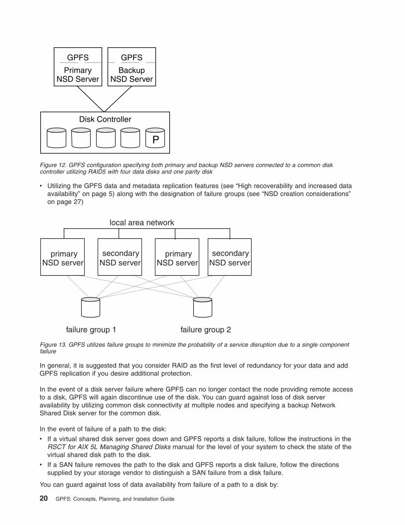
v Utilizing the GPFS data and metadata replication features (see “High recoverability and increased data
availability” on page 5) along with the designation of failure groups (see “NSD creation considerations”
on page 27)
In general, it is suggested that you consider RAID as the first level of redundancy for your data and add
GPFS replication if you desire additional protection.
In the event of a disk server failure where GPFS can no longer contact the node providing remote access
to a disk, GPFS will again discontinue use of the disk. You can guard against loss of disk server
availability by utilizing common disk connectivity at multiple nodes and specifying a backup Network
Shared Disk server for the common disk.
In the event of failure of a path to the disk:
v If a virtual shared disk server goes down and GPFS reports a disk failure, follow the instructions in the
RSCT for AIX 5L Managing Shared Disks manual for the level of your system to check the state of the
virtual shared disk path to the disk.
v If a SAN failure removes the path to the disk and GPFS reports a disk failure, follow the directions
supplied by your storage vendor to distinguish a SAN failure from a disk failure.
You can guard against loss of data availability from failure of a path to a disk by:
GPFS
NSD ServerPrimary
Disk Controller
GPFS
NSD ServerBackup
P
Figure 12. GPFS configuration specifying both primary and backup NSD servers connected to a common disk
controller utilizing RAID5 with four data disks and one parity disk
Figure 13. GPFS utilizes failure groups to minimize the probability of a service disruption due to a single component
failure
20 GPFS: Concepts, Planning, and Installation Guide

v Creating primary and backup NSD servers for all disks. As GPFS determines the available connections
to disks in the file system, it is suggested you always define NSD servers for the disks. In a SAN
configuration where NSD servers have also been defined, if the physical connection is broken, GPFS
dynamically switches to the primary NSD server and continues to provide data. When GPFS discovers
the path has been repaired, it falls back to local disk access. This is the default behavior, and can be
changed with the -o useNSDserver file system mount option on the mmmount, mount, mmchfs, and
mmremotefs commands.
v Utilizing the Multiple Path I/O (MPIO) feature of AIX to define alternate paths to a device for failover
purposes. Failover is a path-management algorithm that improves the reliability and availability of a
device because the system automatically detects when one I/O path fails and reroutes I/O through an
alternate path. All Small Computer System Interface (SCSI) Self Configured SCSI Drive (SCSD) disk
drives are automatically configured as MPIO devices. Other devices can be supported, providing the
device driver is compatible with the MPIO implementation in AIX. For more information about MPIO, see
the:
– AIX 5L Version 5.3 System Management Concepts: Operating System and Devices book and search
on Multi-path I/O.
– AIX 5L Version 5.3 System Management Guide: Operating System and Devices book and search on
Multi-path I/O.
v Use Subsystem Device Driver (SDD) or Subsystem Device Driver Path Control Module (SDDPCM) to
give the AIX host the ability to access multiple paths to a single LUN within an Enterprise Storage
Server® (ESS). This ability to access a single logical unit number (LUN) on multiple paths allows for a
higher degree of data availability in the event of a path failure. Data can continue to be accessed within
the ESS as long as there is at least one available path. Without one of these installed, you will lose
access to the LUN in the event of a path failure.
GPFS cluster creation considerations
You create GPFS clusters by issuing the mmcrcluster command. Table 2 details:
v The GPFS cluster creation options provided by the mmcrcluster command
v How to change the options
v The default values are for each option
Note: Refer to theGPFS: Advanced Administration Guide for information on accessing GPFS file systems
in remote clusters and large cluster administration.
Table 2. GPFS cluster creation options
Cluster option Command to change the
option
Default value
“Nodes in your GPFS cluster” on page
22
Add nodes through the
mmaddnode command
None
Delete nodes through the
mmdelnode command
Node designation: Manager or client,
see “Nodes in your GPFS cluster” on
page 22
mmchconfig
Client
Node designation: Quorum or
non-quorum, see “Nodes in your GPFS
cluster” on page 22
Non-quorum
Primary cluster configuration server,
see “GPFS cluster configuration
servers” on page 23
mmchcluster None
Chapter 2. Planning for GPFS 21
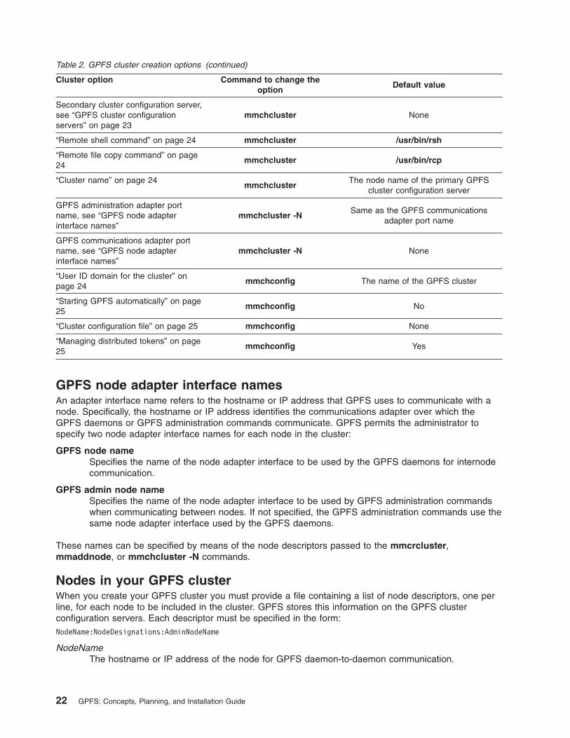
Table 2. GPFS cluster creation options (continued)
Cluster option Command to change the
option
Default value
Secondary cluster configuration server,
see “GPFS cluster configuration
servers” on page 23
mmchcluster None
“Remote shell command” on page 24 mmchcluster /usr/bin/rsh
“Remote file copy command” on page
24
mmchcluster /usr/bin/rcp
“Cluster name” on page 24
mmchcluster
The node name of the primary GPFS
cluster configuration server
GPFS administration adapter port
name, see “GPFS node adapter
interface names”
mmchcluster -N
Same as the GPFS communications
adapter port name
GPFS communications adapter port
name, see “GPFS node adapter
interface names”
mmchcluster -N None
“User ID domain for the cluster” on
page 24
mmchconfig The name of the GPFS cluster
“Starting GPFS automatically” on page
25
mmchconfig No
“Cluster configuration file” on page 25 mmchconfig None
“Managing distributed tokens” on page
25
mmchconfig Yes
GPFS node adapter interface names
An adapter interface name refers to the hostname or IP address that GPFS uses to communicate with a
node. Specifically, the hostname or IP address identifies the communications adapter over which the
GPFS daemons or GPFS administration commands communicate. GPFS permits the administrator to
specify two node adapter interface names for each node in the cluster:
GPFS node name
Specifies the name of the node adapter interface to be used by the GPFS daemons for internode
communication.
GPFS admin node name
Specifies the name of the node adapter interface to be used by GPFS administration commands
when communicating between nodes. If not specified, the GPFS administration commands use the
same node adapter interface used by the GPFS daemons.
These names can be specified by means of the node descriptors passed to the mmcrcluster,
mmaddnode, or mmchcluster -N commands.
Nodes in your GPFS cluster
When you create your GPFS cluster you must provide a file containing a list of node descriptors, one per
line, for each node to be included in the cluster. GPFS stores this information on the GPFS cluster
configuration servers. Each descriptor must be specified in the form:
NodeName:NodeDesignations:AdminNodeName
NodeName
The hostname or IP address of the node for GPFS daemon-to-daemon communication.
22 GPFS: Concepts, Planning, and Installation Guide

The hostname or IP address used for a node must refer to the communications adapter over
which the GPFS daemons communicate. Alias interfaces are not allowed. Use the original address
or a name that is resolved by the host command to that original address. You may specify a node
using any of these forms:
Format Example
Short hostname h135n01
Long hostname h135n01.frf.ibm.com
IP address 7.111.12.102
NodeDesignations
An optional, ″-″ separated list of node roles.
v manager | client – Indicates whether a node is part of the node pool from which configuration
managers, file system managers, and token manager can be selected. The special functions of
the file system manager consume extra processing time. See “The file system manager” on
page 73. The default is to not have the node included in the pool.
In general, small systems do not need multiple nodes dedicated for the file system manager.
However, if you are running large parallel jobs, threads scheduled to a node performing these
functions may run slower. As a guide, in a large system there should be a different file system
manager node for each GPFS file system.
v quorum | nonquorum – This designation specifies whether or not the node should be included
in the pool of nodes from which quorum is derived. The default is non-quorum. You must
designate at least one node as a quorum node. It is strongly suggested that you designate the
primary and secondary cluster configuration servers and any primary and secondary NSD
servers as quorum nodes.
How many quorum nodes you designate depends upon whether you use node quorum or node
quorum with tiebreaker disks. See “Quorum” on page 16.
AdminNodeName
Specifies an optional field that consists of a node name to be used by the administration
commands to communicate between nodes.
If AdminNodeName is not specified, the NodeName value is used.
You must follow these rules when creating your GPFS cluster:
v While a node may mount file systems from multiple clusters, the node itself may only be added to a
single cluster through either the mmcrcluster command or the mmaddnode command.
v The default quorum type is node quorum. To enable node quorum with tiebreaker disks, you must issue
the mmchconfig command.
v The node must be available for the command to be successful. If any of the nodes listed are not
available when the command is issued, a message listing those nodes is displayed. You must correct
the problem on each node, create a new input file containing the failed nodes only, and issue the
mmaddnode command to add those nodes.
GPFS cluster configuration servers
You must designate one of the nodes in your GPFS cluster as the primary GPFS cluster configuration
server, where GPFS configuration information is maintained. It is strongly suggested that you also specify
a secondary GPFS cluster configuration server.
Attention: If your primary server fails and you have not designated a secondary server, the GPFS
cluster configuration data files are inaccessible and any GPFS administration commands that are issued,
fail. Similarly, when the GPFS daemon starts up, at least one of the two GPFS cluster configuration
servers must be accessible. See “Cluster configuration data files” on page 87.
Chapter 2. Planning for GPFS 23

Private IP addresses
GPFS uses private IP addresses among cluster nodes that are connected with communications adapters.
To define private IP addresses, use the subnets operand of the mmchconfig command. For more
information and an example, see Using remote access with public and private IP addresses in General
Parallel File System: Advanced Administration.
Note: Standard private IP addresses are located on these subnets:
v 10.0.0.0
v 172.16.0.0
v 192.168.0.0
Remote shell command
The default remote shell command is rsh. This requires that a properly configured .rhosts file exist in the
root user’s home directory on each node in the GPFS cluster.
If you choose to designate the use of a different remote shell command on either the mmcrcluster or the
mmchcluster command, you must specify the fully qualified pathname for the program to be used by
GPFS. You must also ensure:
1. Proper authorization is granted to all nodes in the GPFS cluster.
2. The nodes in the GPFS cluster can communicate without the use of a password.
The remote shell command must adhere to the same syntax as rsh but may implement an alternate
authentication mechanism.
Remote file copy command
The default remote file copy program is rcp. This requires that a properly configured .rhosts file exist in
the root user’s home directory on each node in the GPFS cluster.
If you choose to designate the use of a different remote file copy command on either the mmcrcluster or
the mmchcluster command, you must specify the fully-qualified pathname for the program to be used by
GPFS. You must also ensure:
1. Proper authorization is granted to all nodes in the GPFS cluster.
2. The nodes in the GPFS cluster can communicate without the use of a password.
The remote copy command must adhere to the same syntax as rcp but may implement an alternate
authentication mechanism.
Cluster name
Provide a name for the cluster by issuing the -C option on the mmcrcluster command. If the
user-provided name contains dots, it is assumed to be a fully qualified domain name. Otherwise, to make
the cluster name unique in a multiple cluster environment, GPFS appends the domain name of the primary
cluster configuration server. If the -C option is not specified, the cluster name defaults to the hostname of
the primary cluster configuration server. The name of the cluster may be changed at a later time by issuing
the -C option on the mmchcluster command.
The cluster name is applicable when GPFS file systems are mounted by nodes belonging to other GPFS
clusters. See the mmauth and the mmremotecluster commands.
User ID domain for the cluster
The user ID domain for a cluster when accessing a file system remotely. This option is further explained in
the GPFS: Advanced Administration Guide and the white paper entitled UID Mapping for GPFS in a
Multi-Cluster Environment at www.ibm.com/servers/eserver/clusters/library/wp_aix_lit.html
24 GPFS: Concepts, Planning, and Installation Guide

Starting GPFS automatically
Specify whether to start GPFS automatically on all nodes in the cluster whenever they come up with the
autoload attribute. The default is for GPFS to not automatically start GPFS on all nodes. You may change
this by specifying the autoload=yes on the mmchconfig command. This eliminates the need to start
GPFS by issuing the mmstartup command when a node comes back up.
Cluster configuration file
GPFS provides you with default configuration options that may generically apply to most systems. You
may:
v Accept the system defaults at cluster creation time and tune your system after the cluster is created by
issuing the mmchconfig command (see Chapter 7, “Configuring and tuning your system for GPFS,” on
page 61). This is the suggested method.
v Experienced users may use a customized cluster configuration file on the mmcrcluster command. For
detailed information, please see the GPFS: Administration and Programming Reference.
Managing distributed tokens
GPFS implements distributed locking using token-based lock management. In GPFS, the
distributedTokenServer option of the mmchconfig command allows you to distribute the token server
workload over multiple token manager nodes in a cluster. Distributing token management among file
system manager nodes reduces system delays associated with a lockable object waiting to obtaining a
token.
When the file system is initially mounted with distributedTokenServer in the default state (yes), the file
system manager is the only token server. However, when the number of external mounts reaches a
threshold, the file system manager appoints additional manager nodes as token servers. You can disable
the distributed token manager feature by setting distributedTokenServer to no. If set to no, the file
system manager continues to act as the only token server no matter how many nodes mount the file
system.
Notes:
1. The total number of token manager nodes depends on the number of manager nodes you defined in
the cluster.
2. If you only designated one node as a manager node, you can only have one token server regardless
of the distributedTokenServer setting.
3. Once the token state has been distributed, it remains distributed until all external mounts have gone
away.
4. The maxFilesToCache and maxStatCache parameters are indirectly affected by multiple token
manager nodes as distributing tokens across multiple nodes could allow more tokens than if you only
had one token server.
5. Refer to the General Parallel File System: Advanced Administration Guide for details on distributed
token managers.
Disk considerations
Proper planning for your GPFS installation includes:
v Ensuring you have sufficient disks to meet the expected I/O load. In GPFS terminology, a disk may be a
physical disk or a RAID device. With GPFS 2.3 or later, you may have up to 268 million disks in the file
system. However, to achieve this maximum limit, you must recompile GPFS.
Notes:
1. The actual number of disks in your system may be constrained by products other than the version of
GPFS installed on your system.
Chapter 2. Planning for GPFS 25
2. With file systems created with GPFS 2.3 or later, the theoretical limit on the maximum number of
disks in a file system has been increased from 4096 to approximately 268 million. However, the
actual limit enforced by the current version of GPFS is 2048. It can be increased if necessary
(please contact IBM to discuss increasing the limit).
v Ensuring you have sufficient free disk space.
If your system contains AIX nodes with NSDs created on existing virtual shared disks, sufficient free
disk space needs to be kept in /var for the correct operation of the IBM Recoverable Virtual Shared
Disk component. While GPFS does not use large amounts of /var, this component requires several
megabytes to correctly support GPFS recovery. Failure to supply this space on all nodes may appear as
a hang in your GPFS file system when recovering failed nodes.
v Ensuring you have sufficient connectivity (adapters and buses) between disks and network shared disk
servers.
v Deciding how your disks will be connected. Supported types of disk connectivity include:
1. All disks are SAN-attached to all nodes in all clusters which access the file.
In this configuration, every node sees the same disk simultaneously and has a corresponding disk
device entry in /dev.
2. Each disk is connected to a single primary NSD server node and, if specified, a single backup NSD
server node.
In this configuration, a single node with connectivity to a disk performs data shipping to all other
nodes. This node is called a primary NSD server. Additionally, it is suggested that you define a
backup NSD server to guard against the loss of the primary disk server. When using a backup NSD
server, both primary and backup disk servers must have connectivity to the same disks. Note that in
this configuration, all other nodes will receive their data over the local area network from the primary
and, if specified, backup NSD server.
3. A combination of SAN-attached and an NSD server configuration.
Configuration consideration:
– If the node has a physical or virtual attachment to the disk and that connection fails, the node
switches to utilizing any specified NSD server to perform I/O. For this reason it is suggested that
NSDs be defined with primary and backup servers, even if all nodes have physical attachments to
the disk.
– Configuring GPFS disks without an NSD server stops the serving of data when the direct path to the
disk is lost. This may be a preferable option for nodes requiring a higher speed data connection
provided through a SAN as opposed to a lower speed network NSD server connection. Parallel jobs
using MPI often have this characteristic.
– The -o useNSDserver file system mount option on the mmmount, mount, mmchfs, and
mmremotefs commands can be used to specify the disk discovery, and limit or eliminate switching
from local access to NSD server access, or the other way around.
v Deciding if you will use storage pools to manage your disks.
Storage pools allow you to manage your file system’s storage in groups. You may now partition your
storage based on such factors as performance, locality, and reliability. Files are assigned to a storage
pool based on defined policies.
Policies provide for:
– Placing files in a specific storage pool when the files are created
– Migrating files from one storage pool to another
– File deletion based on file characteristics
See the GPFS: Advanced Administration Guide.
Disk considerations include:
1. “NSD creation considerations” on page 27
2. “NSD server considerations” on page 29
26 GPFS: Concepts, Planning, and Installation Guide

3. “File system descriptor quorum” on page 30
NSD creation considerations
You must prepare each physical disk you intend to use with GPFS as an NSD through the mmcrnsd
command. NSDs may be created on:
v Physical disks
– An hdisk or vpath on AIX
– A block disk device or a disk partition on Linux
v Virtual shared disks:
– An RSCT peer domain virtual shared disk, see Reliable Scalable Cluster Technology: Managing
Shared Disks
Note: When you are using the High Performance Switch (HPS) in your configuration it is suggested you
process your disks in two steps:
1. Create virtual shared disks on each physical disk through the mmcrvsd command.
2. Using the rewritten disk descriptors from the mmcrvsd command, create NSDs through the
mmcrnsd command.
The mmcrnsd command expects as input a file, DescFile, containing a disk descriptor, one per line, for
each of the disks to be processed. Disk descriptors have the format:
DiskName:PrimaryServer:BackupServer:DiskUsage:FailureGroup:DesiredName:StoragePool
DiskName
The block device name appearing in /dev for the disk you want to define as an NSD. Examples of
disks accessible through a block device are SAN-attached disks or virtual shared disks. If a
PrimaryServer node is specified, DiskName must be the /dev name for the disk device on the
primary NSD server node. See the Frequently Asked Questions at publib.boulder.ibm.com/infocenter/clresctr/topic/com.ibm.cluster.gpfs.doc/ gpfs_faqs/gpfsclustersfaq.html for the latest
supported disk types.
In the AIX environment, GPFS provides the mmcrvsd command to ease configuration of virtual
shared disks. This command allows you to configure a virtual shared disk and make it accessible
to nodes connected over a High Performance Switch. In addition, you can use the output disk
descriptor file from the mmcrvsd command as input to the mmcrnsd command.
Note: The virtual shared disk names listed in output disk descriptor file appear as /dev block
devices on switch attached nodes.
PrimaryServer
The name of the primary NSD server node.
If this field is omitted, the disk is assumed to be SAN-attached to all nodes in the cluster. If not all
nodes in the cluster have access to the disk, or if the file system to which the disk belongs is to be
accessed by other GPFS clusters, PrimaryServer must be specified.
BackupServer
The name of the backup NSD server node.
If the PrimaryServer has been specified and this field is omitted, it is assumed you do not want
failover in the event that the PrimaryServer fails. If BackupServer is specified and the
PrimaryServer has not been specified, the command fails.
The hostname or IP address must refer to the communications adapter over which the GPFS
daemons communicate. Alias interfaces are not allowed. Use the original address or a name that
is resolved by the host command to that original address. You may specify a node using any of
these forms:
Chapter 2. Planning for GPFS 27

Format Example
Short hostname h125n01
Long hostname h125n01.frn.ibm.com
IP address 8.112.11.113
DiskUsage
Specify a disk usage or accept the default. This field is ignored by the mmcrnsd command, and is
passed unchanged to the output descriptor file produced by the mmcrnsd command. Possible
values are:
v dataAndMetadata Indicates that the disk contains both data and metadata. This is the default.
v dataOnly Indicates that the disk contains data and does not contain metadata.
v metadataOnly Indicates that the disk contains metadata and does not contain data.
v descOnly Indicates that the disk contains no data and no metadata. Such a disk is used solely
to keep a copy of the file system descriptor, and can be used as a third failure group in certain
disaster recovery configurations.
FailureGroup
A number identifying the failure group to which this disk belongs. You can specify any value from
-1 (where -1 indicates that the disk has no point of failure in common with any other disk) to 4000.
If you do not specify a failure group, the value defaults to the NSD primary server node number
plus 4000. If an NSD server node is not specified, the value defaults to -1. GPFS uses this
information during data and metadata placement to assure that no two replicas of the same block
are written in such a way as to become unavailable due to a single failure. All disks that are
attached to the same NSD server or adapter should be placed in the same failure group.
This field is ignored and passed unchanged to the output descriptor file written by either the
mmcrvsd command or the mmcrnsd command.
DesiredName
Specify the name you desire for the NSD to be created. This name must not already be used as
another GPFS disk name, and it must not begin with the reserved string ’gpfs’.
Note: This name can contain only the characters: ’A’ through ’Z’, ’a’ through ’z’, ’0’ through ’9’, or
’_’ (the underscore). All other characters are not valid.
If a desired name is not specified, the NSD is assigned a name according to the convention:
gpfsNNnsd where NN is a unique nonnegative integer not used in any prior NSD.
StoragePool
Specifies the name of the storage pool that the NSD is assigned to. Storage pool names:
v Must be unique within a file system, but not across file systems
v Should not be larger than 255 alphanumeric characters
v Are case sensitive
– MYpool and myPool are distinct storage pools
If this name is not provided, the default is system. Only the system pool may contain
metadataOnly, dataAndMetadata, or descOnly disks.
Upon successful completion of the mmcrnsd command the disk descriptors in the input file are rewritten:
v The original descriptor line is copied and commented out.
v The physical device name is replaced with the assigned unique global name.
v The primary and backup server names are omitted.
v The DiskUsage, FailureGroup, and StoragePool fields, when provided by the user, are not changed. If
the those values are not provided, the appropriate default values are inserted.
28 GPFS: Concepts, Planning, and Installation Guide
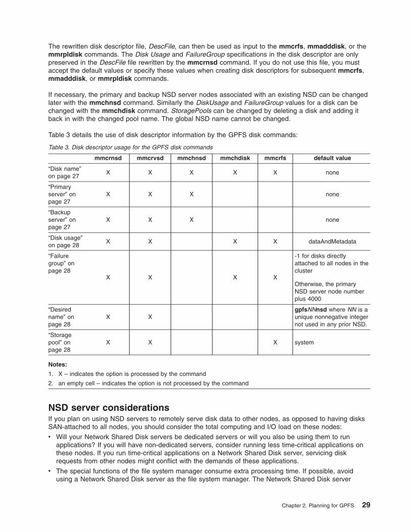
The rewritten disk descriptor file, DescFile, can then be used as input to the mmcrfs, mmadddisk, or the
mmrpldisk commands. The Disk Usage and FailureGroup specifications in the disk descriptor are only
preserved in the DescFile file rewritten by the mmcrnsd command. If you do not use this file, you must
accept the default values or specify these values when creating disk descriptors for subsequent mmcrfs,
mmadddisk, or mmrpldisk commands.
If necessary, the primary and backup NSD server nodes associated with an existing NSD can be changed
later with the mmchnsd command. Similarly the DiskUsage and FailureGroup values for a disk can be
changed with the mmchdisk command. StoragePools can be changed by deleting a disk and adding it
back in with the changed pool name. The global NSD name cannot be changed.
Table 3 details the use of disk descriptor information by the GPFS disk commands:
Table 3. Disk descriptor usage for the GPFS disk commands
mmcrnsd mmcrvsd mmchnsd mmchdisk mmcrfs default value
“Disk name”
on page 27
X X X X X none
“Primary
server” on
page 27
X X X none
“Backup
server” on
page 27
X X X none
“Disk usage”
on page 28
X X X X dataAndMetadata
“Failure
group” on
page 28
X X X X
-1 for disks directly
attached to all nodes in the
cluster
Otherwise, the primary
NSD server node number
plus 4000
“Desired
name” on
page 28
X X
gpfsNNnsd where NN is a
unique nonnegative integer
not used in any prior NSD.
“Storage
pool” on
page 28
X X X system
Notes:
1. X – indicates the option is processed by the command
2. an empty cell – indicates the option is not processed by the command
NSD server considerations
If you plan on using NSD servers to remotely serve disk data to other nodes, as opposed to having disks
SAN-attached to all nodes, you should consider the total computing and I/O load on these nodes:
v Will your Network Shared Disk servers be dedicated servers or will you also be using them to run
applications? If you will have non-dedicated servers, consider running less time-critical applications on
these nodes. If you run time-critical applications on a Network Shared Disk server, servicing disk
requests from other nodes might conflict with the demands of these applications.
v The special functions of the file system manager consume extra processing time. If possible, avoid
using a Network Shared Disk server as the file system manager. The Network Shared Disk server
Chapter 2. Planning for GPFS 29

consumes both memory and processor cycles that could impact the operation of the file system
manager. See “The file system manager” on page 73.
v The actual processing capability required for Network Shared Disk service is a function of the
application I/O access patterns, the type of node, the type of disk, and the disk connection. You can
later run iostat on the server to determine how much of a load your access pattern will place on a
Network Shared Disk server.
v Providing sufficient disks and adapters on the system to yield the required I/O bandwidth. Dedicated
Network Shared Disk servers should have sufficient disks and adapters to drive the I/O load you expect
them to handle.
v Knowing approximately how much storage capacity you will need for your data.
You should consider what you want as the default behavior for switching between local access and NSD
server access in the event of a failure. To set this configuration, use the -o useNSDserver file system
mount option of the mmmount, mount, mmchfs, and mmremotefs commands to:
v Specify the disk discovery behavior
v Limit or eliminate switching from either:
– Local access to NSD server access
– NSD server access to local access
You should consider specifying how long to wait for an NSD server to come online before allowing a file
system mount to fail because the server is not available. The mmchconfig command has these options:
nsdServerWaitTimeForMount
When a node is trying to mount a file system whose disks depend on NSD servers, this option
specifies the number of seconds to wait for those servers to come up. If a server recovery is
taking place, the wait time you are specifying with this option starts after recovery completes.
Note: The decision to wait for servers is controlled by the nsdServerWaitTimeWindowOnMount
option.
nsdServerWaitTimeWindowOnMount
Specifies a window of time (in seconds) during which a mount can wait for NSD servers as
described for the nsdServerWaitTimeForMount option. The window begins when quorum is
established (at cluster startup or subsequently), or at the last known failure times of the NSD
servers required to perform the mount.
Notes:
1. When a node rejoins a cluster, it resets all the failure times it knew about within that cluster.
2. Because a node that rejoins a cluster resets its failure times within that cluster, the NSD server
failure times are also reset.
3. When a node attempts to mount a file system, the GPFS code checks the cluster formation
criteria first. If that check falls outside the window, it will then check for NSD server fail times
being in the window.
File system descriptor quorum
There is a structure in GPFS called the file system descriptor that is initially written to every disk in the file
system, but is replicated on a subset of the disks as changes to the file system occur, such as adding or
deleting disks. Based on the number of failure groups and disks, GPFS creates between one and five
replicas of the descriptor:
v If there are at least five different failure groups, five replicas are created.
v If there are at least three different disks, three replicas are created.
v If there are only one or two disks, a replica is created on each disk.
30 GPFS: Concepts, Planning, and Installation Guide
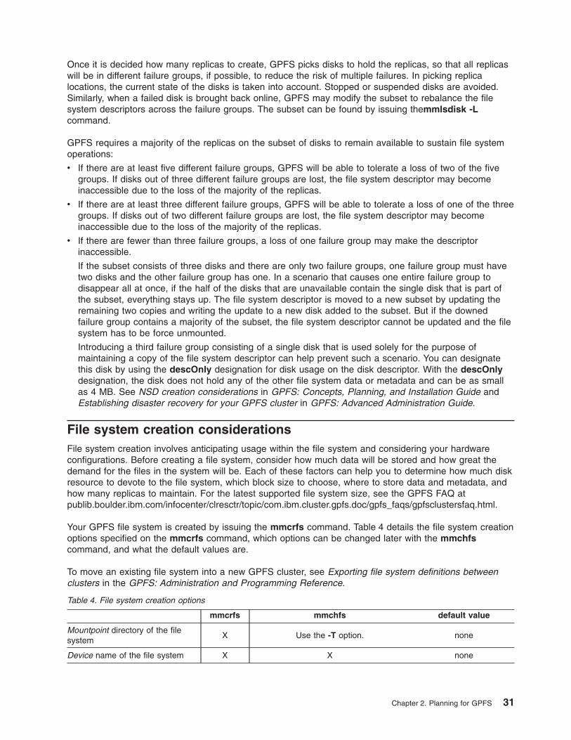
Once it is decided how many replicas to create, GPFS picks disks to hold the replicas, so that all replicas
will be in different failure groups, if possible, to reduce the risk of multiple failures. In picking replica
locations, the current state of the disks is taken into account. Stopped or suspended disks are avoided.
Similarly, when a failed disk is brought back online, GPFS may modify the subset to rebalance the file
system descriptors across the failure groups. The subset can be found by issuing themmlsdisk -L
command.
GPFS requires a majority of the replicas on the subset of disks to remain available to sustain file system
operations:
v If there are at least five different failure groups, GPFS will be able to tolerate a loss of two of the five
groups. If disks out of three different failure groups are lost, the file system descriptor may become
inaccessible due to the loss of the majority of the replicas.
v If there are at least three different failure groups, GPFS will be able to tolerate a loss of one of the three
groups. If disks out of two different failure groups are lost, the file system descriptor may become
inaccessible due to the loss of the majority of the replicas.
v If there are fewer than three failure groups, a loss of one failure group may make the descriptor
inaccessible.
If the subset consists of three disks and there are only two failure groups, one failure group must have
two disks and the other failure group has one. In a scenario that causes one entire failure group to
disappear all at once, if the half of the disks that are unavailable contain the single disk that is part of
the subset, everything stays up. The file system descriptor is moved to a new subset by updating the
remaining two copies and writing the update to a new disk added to the subset. But if the downed
failure group contains a majority of the subset, the file system descriptor cannot be updated and the file
system has to be force unmounted.
Introducing a third failure group consisting of a single disk that is used solely for the purpose of
maintaining a copy of the file system descriptor can help prevent such a scenario. You can designate
this disk by using the descOnly designation for disk usage on the disk descriptor. With the descOnly
designation, the disk does not hold any of the other file system data or metadata and can be as small
as 4 MB. See NSD creation considerations in GPFS: Concepts, Planning, and Installation Guide and
Establishing disaster recovery for your GPFS cluster in GPFS: Advanced Administration Guide.
File system creation considerations
File system creation involves anticipating usage within the file system and considering your hardware
configurations. Before creating a file system, consider how much data will be stored and how great the
demand for the files in the system will be. Each of these factors can help you to determine how much disk
resource to devote to the file system, which block size to choose, where to store data and metadata, and
how many replicas to maintain. For the latest supported file system size, see the GPFS FAQ at
publib.boulder.ibm.com/infocenter/clresctr/topic/com.ibm.cluster.gpfs.doc/gpfs_faqs/gpfsclustersfaq.html.
Your GPFS file system is created by issuing the mmcrfs command. Table 4 details the file system creation
options specified on the mmcrfs command, which options can be changed later with the mmchfs
command, and what the default values are.
To move an existing file system into a new GPFS cluster, see Exporting file system definitions between
clusters in the GPFS: Administration and Programming Reference.
Table 4. File system creation options
mmcrfs mmchfs default value
Mountpoint directory of the file
system
X Use the -T option. none
Device name of the file system X X none
Chapter 2. Planning for GPFS 31

Table 4. File system creation options (continued)
mmcrfs mmchfs default value
-D {nfs4 | posix} semantics for a
’deny-write open lock’
X X posix
-F DiskDesc for each disk in your
file system X
Issue the mmadddisk and mmdeldisk
commands respectively to add or delete
disks from the file system
none
-A {yes | no | automount} when
to mount the file system
X X yes
-B BlockSize 16K, 64K, 256K,
512K, 1024K, or 1M data block
size
X
this value cannot be changed without
recreating the file system 256K
-E {yes | no} to report exact
mtime values
X X yes
-k {posix | nfs4 |all} authorization
types supported by the file system
X X posix
-m DefaultMetadataReplicas X X 1
- M MaxMetadataReplicas X this value cannot be changed 1
-N NumInodes determine the
maximum number of files in the
file system
X Use the -F option. file system size/1 MB
-n NumNodes that will mount the
file system
X
this value cannot be changed after the
file system has been created
32
-o MountOptions to be passed to
the mount command
X none
-Q {yes | no } to activate quota X X no
-r DefaultDataReplicas X X 1
-RMaxDataReplicas X this value cannot be changed 1
-S {yes | no} to suppress periodic
updating of atime values
X X no
-V to migrate file system format to
latest level
X none
-v {yes | no} to verify disk usage X yes
-W NewDeviceName to assign a
new device name to the file
system
X none
-z yes | no to enable DMAPI X X no
Notes:
1. X – indicates the option is available on the command
2. an empty cell – indicates the option is not available on the command
Mountpoint directory
GPFS does not have a default mountpoint directory for the file system. You must specify the directory
when creating a file system. Creating filesets is part of the process of laying out the namespace for the file
system. While filesets can be created at any time, partitioning an existing file system into filesets or
reorganizing the fileset structure of a file system can be time-consuming. Since filesets have quota and
policy implications, it is useful to give some thought to filesets when establishing the hierarchy of a new file
system.
32 GPFS: Concepts, Planning, and Installation Guide

Filesets can be used for any reasonably independent subtree of the file system such as the home
directories belonging to a user, project trees, and installation directories for large applications. Generally,
subtrees with characteristic uses or purposes can be beneficially assigned to filesets so that policy
statements can be concisely applied to them. When sharing a pool of storage between various uses that
are aligned by hierarchy, rather than by user or group, the fileset quota can be useful; user and project
directories are a common example of this situation.
Note: When using the mmchfs command, the -T option can be used to change the file system
mountpoint.
Device name of the file system
File system names must be unique within a GPFS clusters. However, two different clusters can have two
distinct file systems with the same name. The device name of the file system does not need to be fully
qualified. fs0 is as acceptable as /dev/fs0. Do not specify an existing entry in /dev.
NFS V4 ’deny-write open lock’
Specify whether a ’deny-write open lock’ blocks writes, which is expected and required by NFS V4. See
Managing GPFS access control lists and NFS export in the GPFS: Administration and Programming
Reference
nfs4 Must be specified for file systems supporting NFS V4.
posix Specified for file systems supporting NFS V3 or ones which are not NFS exported. This is the
default.
posix allows NFS writes even in the presence of a deny-write open lock.
Disks for your file system
Prior to issuing the mmcrfs command you must decide if you will:
1. Create new disks through the mmcrnsd command.
2. Select NSDs no longer in use by another GPFS file system. Issue the mmlsnsd -F command to
display the available disks.
See “Disk considerations” on page 25.
Deciding how the file system is mounted
Specify when the file system is to be mounted:
yes When the GPFS daemon starts. This is the default.
no Manual mount.
automount When the file system is first accessed.
This can be changed at a later time by using the -A option on the mmchfs command.
Considerations:
1. GPFS mount traffic may be lessened by using the automount feature to mount the file system when it
is first accessed instead of at GPFS startup. Automatic mounts only produce additional control traffic at
the point that the file system is first used by an application or user. Mounts at GPFS startup on the
other hand produce additional control traffic at every GPFS startup. Thus startup of hundreds of nodes
at once may be better served by using automatic mounts.
2. Automatic mounts will fail if the node does not have the operating systems automount support enabled
for the file system.
3. When exporting file systems for NFS mounts, it may be useful to mount the file system when GPFS
starts.
Chapter 2. Planning for GPFS 33

Block size
The size of data blocks in a file system may be specified at file system creation by using the -B option on
the mmcrfs command or allowed to default to 256 KB. This value cannot be changed without recreating
the file system.
GPFS offers five block sizes for file systems: 16 KB, 64 KB, 256 KB, 512 KB, and 1024 KB or 1 MB. This
value should be specified with the character K or M as appropriate. For example 512K. You should choose
the block size based on the application set that you plan to support and if you are using RAID hardware:
v The 256 KB block size is the default block size and normally is the best block size for file systems that
contain large files accessed in large reads and writes.
v The 16 KB block size optimizes use of disk storage at the expense of large data transfers.
v The 64 KB block size offers a compromise if there are a mix of many files of approximately 64K or less
in size. It makes more efficient use of disk space than 256 KB while allowing faster I/O operations than
16 KB.
v The 1024 KB or 1 MB block sizes are more efficient if the dominant I/O pattern is sequential access to
large files (1 MB or more).
If you plan to use RAID devices in your file system, a larger block size may be more effective and help
avoid the penalties involved in small block write operations to RAID devices. For example, in a RAID
configuration utilizing 4 data disks and 1 parity disk (a 4+P configuration), which utilizes a 64 KB stripe
size, the optimal file system block size would be an integral multiple of 256 KB (4 data disks × 64 KB
stripe size = 256 KB). A block size of an integral multiple of 256 KB results in a single data write that
encompasses the 4 data disks and a parity-write to the parity disk. If a block size smaller than 256 KB,
such as 64 KB, is used, write performance is degraded by the read-modify-write behavior. A 64 KB
block size results in a single disk writing 64 KB and a subsequent read from the three remaining disks
in order to compute the parity that is then written to the parity disk. The extra read degrades
performance.
The choice of block size also affects the performance of certain metadata operations, in particular, block
allocation performance. GPFS block allocation map is stored in blocks, similar to regular files. When
block size is small:
– It takes more blocks to store a given amount of data resulting in additional work to allocate those
blocks
– One block of allocation map data contains less information
Note: The choice of block size is particularly important for large file systems. For file systems larger
than 100 TB, you should use a block size of at least 256 KB.
Fragments and subblocks
GPFS divides each block into 32 subblocks. Files smaller than one block size are stored in fragments,
which are made up of one or more subblocks. Large files are stored in a number of full blocks plus zero or
more subblocks to hold the data at the end of the file.
The block size is the largest contiguous amount of disk space allocated to a file and therefore the largest
amount of data that can be accessed in a single I/O operation. The subblock is the smallest unit of disk
space that can be allocated. For a block size of 256 KB, GPFS reads as much as 256 KB of data in a
single I/O operation and small files can occupy as little as 8 KB of disk space. With a block size of 16 KB,
small files occupy as little as 512 bytes of disk space (not counting the inode), but GPFS is unable to read
more than 16 KB in a single I/O operation.
atime values
atime represents the time when the file was last accessed. The -S parameter controls the updating of the
atime value. The default is -S no, which results in updating atime locally in memory whenever a file is
read, but the value is not visible to other nodes until after the file is closed. If an accurate atime is needed,
34 GPFS: Concepts, Planning, and Installation Guide
the application must use the GPFS calls gpfs_stat() and gpfs_fstat(). When -S yes is specified, or the file
system is mounted read-only, the updating of the atime value is suppressed. See “Exceptions to Open
Group technical standards” on page 95.
mtime values
mtime represents the time when the file was last modified. The -E parameter controls the frequency of
updating of the mtime value. The default is -E yes, which results in the stat() and fstat() calls reporting
exact mtime values. Specifying -E no results in the stat() and fstat() calls reporting the mtime value
available at the completion of the last sync period. This may result in the calls not always reporting the
exact mtime value. Note that regardless of the -E setting, the GPFS calls gpfs_stat() and gpfs_fstat()
always report the exact mtime. See “Exceptions to Open Group technical standards” on page 95.
File system authorization
The type of authorization for the file system is specified on the -k option on the mmcrfs command or
changed at a later time by using the -k option on the mmchfs command:
posix Traditional GPFS access control lists (ACLs) only (NFS V4 ACLs are not allowed).
nfs4 Support for NFS V4 ACLs only. Users are not allowed to assign traditional ACLs to any file system
objects. This should not be specified unless the file system is going to be exported to NFS V4
clients.
all Allows for the coexistence of POSIX and NFS V4 ACLs within a file system. This should not be
specified unless at least one file within the file system is going to be exported to NFS V4 clients.
File system recoverability parameters
The metadata (inodes, directories, and indirect blocks) and data replication parameters are set at the file
system level and apply to all files. They are initially set for the file system when issuing the mmcrfs
command. They can be changed for an existing file system using the mmchfs command, but
modifications only apply to files subsequently created. To apply the new replication values to existing files
in a file system, issue the mmrestripefs command.
Metadata and data replication are specified independently. Each has a default replication factor of 1 (no
replication) and a maximum replication factor. Although replication of metadata is less costly in terms of
disk space than replication of file data, excessive replication of metadata also affects GPFS efficiency
because all metadata replicas must be written. In general, more replication uses more space. When
considering data replication for files accessible to Tivoli® SANergy, see SANergy export considerations in
General Parallel File System: Advanced Administration Guide.
Default metadata Replicas
The default number of copies of metadata for all files in the file system may be specified at file system
creation by using the -m option on the mmcrfs command or changed at a later time by using the -m
option on the mmchfs command. This value must be equal to or less than MaxMetadataReplicas, and
cannot exceed the number of failure groups with disks that can store metadata. The allowable values are
1 or 2, with a default of 1.
Maximum metadata replicas
The maximum number of copies of metadata for all files in the file system may be specified at file system
creation by using the -M option on the mmcrfs command or allowed to default to 1. The allowable values
are 1 or 2, but it cannot be lower than DefaultMetadataReplicas. This value cannot be changed.
Default data replicas
The default replication factor for data blocks may be specified at file system creation by using the -r option
on the mmcrfs command or changed at a later time by using the -r option on the mmchfs command. This
value must be equal to or less than MaxDataReplicas, and the value cannot exceed the number of failure
groups with disks that can store data. The allowable values are 1 and 2, with a default of 1.
Chapter 2. Planning for GPFS 35
If you want to change the data replication factor for the entire file system, the data disk in each storage
pool must have a failure group that is equal to or greater than the replication factor. For example, you will
get a failure with error messages if you try to change the replication factor for a file system to 2 but the
storage pool only has one failure group.
This is an example of a successful update to the data replication factor:
mmlsdisk fs2
disk driver sector failure holds holds storage
name type size group metadata data status availability pool
------------ -------- ------ ------- -------- ----- ------------- ------------ ------------
gpfs1005nsd nsd 512 2 no yes ready up sp4
gpfs2nsd nsd 512 2 no yes ready up sp3
gpfs1004nsd nsd 512 4001 yes yes ready up system
gpfs1006nsd nsd 512 4001 no yes ready up sp3
gpfs1007nsd nsd 512 4001 no yes ready up sp4
gpfs1008nsd nsd 512 2 yes yes ready up system
gpfs3nsd nsd 512 3 no yes ready up sp1
gpfs1002nsd nsd 512 4001 no yes ready up sp1
GPFS: 6027-741 Attention: Due to an earlier configuration change the file system
may contain data that is at risk of being lost.
mmchfs fs2 -r 2
mmlsfs fs2 -r
flag value description
---- -------------- -----------------------------------------------------
-r 2 Default number of data replicas
Maximum data replicas
The maximum number of copies of data blocks for a file may be specified at file system creation by using
the -R option on the mmcrfs command or allowed to default to 1. The allowable values are 1 and 2, but
cannot be lower than DefaultDataReplicas. This value cannot be changed.
Number of nodes mounting the file system
The estimated number of nodes that will mount the file system may be specified at file system creation by
using the -n option on the mmcrfs command or allowed to default to 32.
When creating a GPFS file system, over estimate the number of nodes that will mount the file system.
This input is used in the creation of GPFS data structures that are essential for achieving the maximum
degree of parallelism in file system operations (see Appendix A, “GPFS architecture,” on page 73).
Although a larger estimate consumes a bit more memory, insufficient allocation of these data structures
can limit node ability to process certain parallel requests efficiently, such as the allotment of disk space to
a file. If you cannot predict the number of nodes, allow the default value to be applied. Specify a larger
number if you expect to add nodes, but avoid wildly overestimating as this can affect buffer operations.
Note: This value cannot be changed later.
Maximum number of files
The maximum number of files in a file system may be specified at file system creation by using the -N
option on the mmcrfs command or changed at a later time by using the -F option on the mmchfs
command. This value defaults to the size of the file system at creation divided by 1 MB and cannot exceed
the architectural limit of 2,147,483,647.
These options limit the maximum number of files that may actively exist within the file system. However,
the maximum number of files in the file system may be restricted by GPFS so the control structures
associated with each file do not consume all of the file system space.
36 GPFS: Concepts, Planning, and Installation Guide

Notes:
1. For file systems that will be doing parallel file creates, if the total number of free inodes is not greater
than 5% of the total number of inodes there is the potential for slowdown in file system access. Take
this into consideration when creating or changing your file system. Use the mmdf command to display
the number of free inodes.
2. Excessively increasing the value for the maximum number of files will cause the allocation of too much
disk space for control structures.
Assign mount command options
Options may be passed to the file system mount command using the -o option on the mmchfs command.
Automatic quota activation
Whether or not to automatically activate quotas when the file system is mounted may be specified at file
system creation by using the -Q option on the mmcrfs command or changed at a later time by using the
-Q option on the mmchfs command. After the file system has been mounted, quota values are established
by issuing the mmedquota command and activated by issuing the mmquotaon command. The default is
to not have quotas activated.
The GPFS quota system helps you control the allocation of files and data blocks in a file system. GPFS
quotas can be defined for individual users, groups of users, or filesets. Quotas should be installed by the
system administrator if control over the amount of space used by the individual users, groups of users, or
filesets is desired. When setting quota limits for a file system, the system administrator should consider the
replication factors of the file system. GPFS quota management takes replication into account when
reporting on and determining if quota limits have been exceeded for both block and file usage. In a file
system that has either type of replication (data replication or metadata replication) set to a value of two,
the values reported on by both the mmlsquota and the mmrepquota commands are double the value
reported by the ls command.
GPFS quotas operate with three parameters that you can explicitly set using the mmedquota and
mmdefedquota commands:
1. Soft limit
2. Hard limit
3. Grace period
The soft limits define levels of disk space and files below which the user, group of users, or fileset can
safely operate. The hard limits define the maximum disk space and files the user, group of users, or fileset
can accumulate. Specify hard and soft limits for disk space in units of kilobytes (k or K), megabytes (m or
M), or gigabytes (g or G). If no suffix is provided, the number is assumed to be in bytes.
The grace period allows the user, group of users, or fileset to exceed the soft limit for a specified period of
time (the default period is one week). If usage is not reduced to a level below the soft limit during that
time, the quota system interprets the soft limit as the hard limit and no further allocation is allowed. The
user, group of users, or fileset can reset this condition by reducing usage enough to fall below the soft
limit.
Default quotas
Applying default quotas provides all new users of the file system, groups of users of the file system, or a
fileset with established minimum quota limits. If default quota values are not enabled, a new user, a new
group, or a new fileset has a quota value of zero, which establishes no limit to the amount of space that
can be used.
Chapter 2. Planning for GPFS 37

Default quotas may be set for a file system only if the file system was created with the -Q yes option on
the mmcrfs command, or updated with the -Q option on the mmchfs command. Default quotas may then
be enabled for the file system by issuing the mmdefquotaon command. Default values are established by
issuing the mmdefedquota command.
Quota system files
The GPFS quota system maintains three separate files that contain data about usage and limits. These
files reside in the root directory of the GPFS file systems:
v user.quota
v group.quota
v fileset.quota
All three .quota files are:
v Built with the information provided in the mmedquota and mmdefedquota commands.
v Updated through normal allocation operations throughout the file system and when the mmcheckquota
command is issued.
v Readable by the mmlsquota and mmrepquota commands.
The .quota files are read from the root directory when mounting a file system with quotas enabled. When
these files are read, one of three possible actions take place:
v The files contain quota information and the user wants these files to be used.
v The files contain quota information, however, the user wants different files to be used.
To specify the use of different files, the mmcheckquota command must be issued prior to the mount of
the file system.
v The files do not contain quota information. In this case the mount fails and appropriate error messages
are issued. See the GPFS: Problem Determination Guide for further information regarding mount
failures.
Notes:
1. If these files are not available when mounting the file system, new quota files are created.
2. A fileset quota behaves the same way as a user or group quota.
3. The result of an online quota check may be incomplete when files are being accessed through
SANergy at the time of the file system quota check. See SANergy export considerations in the GPFS:
Advanced Administration Guide. To get an accurate online quota check result, rerun the
mmcheckquota command when SANergy is not active.
Migrate file system format to latest level
Attention: Changing file system format causes the file system to become permanently incompatible with
prior releases of GPFS.
GPFS Version 3.1 supports filesets and storage pools. When you migrate an existing GPFS file system to
the latest version, the migration process automatically creates a "root" fileset and "system" storage pool.
Root filesets
During migration, all existing files and directories are assigned to the root fileset. After migration,
you can:
v Create new filesets with mmcrfileset
v Link filesets into the namespace with mmlinkfileset
v Copy data into the filesets using ordinary file system tools such as cp or tar
Note: Upgrading a file system with quotas enabled will not enable fileset quota. This must be
explicitly enabled using the mmchfs -Q yes command. That command will automatically
create the fileset.quota file in the root directory of the file system.
38 GPFS: Concepts, Planning, and Installation Guide

System storage pools
During migration, all of the disks belonging to an existing file system are assigned to the system
storage pool. When you add new disks, you can assign them to other storage pools. Adding new
disks automatically creates the storage pool named in the disk description. To move a disk already
belonging to the file system to a new storage pool use mmdeldisk followed by mmadddisk.
Notes:
1. After GPFS migration, you may need to change the file system format to the latest format supported by
the currently installed level of GPFS. To change the file system format, use the -V option on the
mmchfs command. Refer to File system format changes for additional information.
2. The migration process does not create an initial policy file. If you are going to use a policy file, you
must create one and install it with the mmchpolicy command.
Disk usage verification
When you create your file system, you may check whether or not the disks you are specifying do not
already belong to an existing file system by using the -v option on the mmcrfs command. The default is to
verify disk usage. You should only specify no when you want to reuse disks that are no longer needed for
an existing GPFS file system. To determine which disks are no longer in use by any file system, issue the
mmlsnsd -F command.
Assign a new device name to the file system
The device name of a file system may be changed using the -W option on the mmchfs command.
Enable DMAPI
Whether or not the file system can be monitored and managed by the GPFS Data Management API
(DMAPI) may be specified at file system creation by using the -z option on the mmcrfs command or
changed at a later time by using the -z option on the mmchfs command. The default is not to enable
DMAPI for the file system. For further information on DMAPI for GPFS, see the GPFS: Data Management
API Guide.
A sample file system creation
To create a file system called gpfs2 with the properties:
v the disks for the file system listed in the file /tmp/gpfs2dsk
v automatically mount the file system when the GPFS daemon starts (-A yes)
v a block size of 256 KB (-B 256K)
v mount it on 32 nodes (-n 32)
v both default replication and the maximum replication for metadata set to two (-m 2 -M 2)
v default replication for data set to one and the maximum replication for data set to two (-r 1 -R 2)
Enter:
mmcrfs /gpfs2 gpfs2 -F /tmp/gpfs2dsk -A yes -B 512K -n 24 -m 2 -M 2 -r 1 -R 2
The system displays information similar to:
The following disks of gpfs2 will be formatted on node k194p03.tes.nnn.com:
hd25n09: size 17796014 KB
hd24n09: size 17796014 KB
hd23n09: size 17796014 KB
Formatting file system ...
Disks up to size 59 GB can be added to storage pool system.
Creating Inode File
56 % complete on Mon Mar 6 15:10:08 2006
100 % complete on Mon Mar 6 15:10:11 2006
Creating Allocation Maps
Chapter 2. Planning for GPFS 39
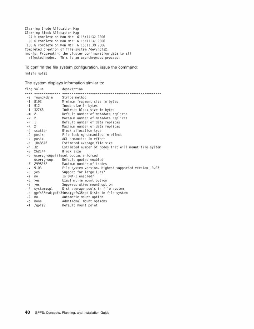
Clearing Inode Allocation Map
Clearing Block Allocation Map
44 % complete on Mon Mar 6 15:11:32 2006
90 % complete on Mon Mar 6 15:11:37 2006
100 % complete on Mon Mar 6 15:11:38 2006
Completed creation of file system /dev/gpfs2.
mmcrfs: Propagating the cluster configuration data to all
affected nodes. This is an asynchronous process.
To confirm the file system configuration, issue the command:
mmlsfs gpfs2
The system displays information similar to:
flag value description
---- -------------- -----------------------------------------------------
-s roundRobin Stripe method
-f 8192 Minimum fragment size in bytes
-i 512 Inode size in bytes
-I 32768 Indirect block size in bytes
-m 2 Default number of metadata replicas
-M 2 Maximum number of metadata replicas
-r 1 Default number of data replicas
-R 2 Maximum number of data replicas
-j scatter Block allocation type
-D posix File locking semantics in effect
-k posix ACL semantics in effect
-a 1048576 Estimated average file size
-n 32 Estimated number of nodes that will mount file system
-B 262144 Block size
-Q user;group;fileset Quotas enforced
user;group Default quotas enabled
-F 2998272 Maximum number of inodes
-V 9.03 File system version. Highest supported version: 9.03
-u yes Support for large LUNs?
-z no Is DMAPI enabled?
-E yes Exact mtime mount option
-S yes Suppress atime mount option
-P system;sp1 Disk storage pools in file system
-d gpfs33nsd;gpfs34nsd;gpfs35nsd Disks in file system
-A no Automatic mount option
-o none Additional mount options
-T /gpfs2 Default mount point
40 GPFS: Concepts, Planning, and Installation Guide

Part 2. Establishing GPFS on your system
© Copyright IBM Corp. 1998, 2006 41

42 GPFS: Concepts, Planning, and Installation Guide

Chapter 3. Steps to establishing and starting your GPFS
cluster
Follow these steps to establish your GPFS cluster:
1. See the GPFS FAQ at publib.boulder.ibm.com/infocenter/clresctr/topic/com.ibm.cluster.gpfs.doc/gpfs_faqs/gpfsclustersfaq.html for the latest recommendations on establishing a GPFS cluster.
2. Place the GPFS code on your system:
v For existing systems, see Chapter 6, “Migration, coexistence and compatibility,” on page 53.
v For new systems:
– For your Linux nodes, see Chapter 4, “Installing GPFS on Linux nodes,” on page 45.
– For your AIX nodes, see Chapter 5, “Installing GPFS on AIX 5L nodes,” on page 49.
3. Decide which nodes in your system will be quorum nodes (see “Quorum” on page 16 ) .
4. Create your GPFS cluster by issuing the mmcrcluster command. See “GPFS cluster creation
considerations” on page 21.
After your GPFS cluster has been established:
1. Ensure you have configured and tuned your system according to the values suggested in Configuring
and tuning your system for GPFS.
2. Start GPFS by issuing the mmstartup command. See the GPFS: Administration and Programming
Reference.
3. Create new disks for use in your file systems by issuing the mmcrnsd command. See “NSD creation
considerations” on page 27.
4. Create new file systems by issuing the mmcrfs command. See “File system creation considerations”
on page 31.
5. If any existing files systems have not already been moved to the new GPFS cluster, do so. For file
systems created prior to GPFS version 2 release 3, see Chapter 6, “Migration, coexistence and
compatibility,” on page 53. For file systems already migrated to or created on a GPFS version 2
release 3 system, see the section on Exporting file system definitions between clusters in the GPFS:
Administration and Programming Reference.
6. Mount your file systems.
7. As an optional step, you can also create a temporary directory (/tmp/mmfs) to collect problem
determination data. If you decide to do so, the /tmp/mmfs directory should not be placed in a GPFS
file system as it might not be available should GPFS fail. However, the /tmp/mmfs directory can be a
symbolic link to another location if more space can be found there.
If a problem should occur, GPFS may write 200 MB or more of problem determination data into
/tmp/mmfs. These files must be manually removed when any problem determination is complete. This
should be done promptly so that a NOSPACE condition is not encountered during the next failure. An
alternate path may be specified through the mmchconfig command.
© Copyright IBM Corp. 1998, 2006 43

44 GPFS: Concepts, Planning, and Installation Guide
Chapter 4. Installing GPFS on Linux nodes
It is suggested you read Chapter 2, “Planning for GPFS,” on page 15 and the GPFS FAQ at
publib.boulder.ibm.com/infocenter/clresctr/topic/com.ibm.cluster.gpfs.doc/gpfs_faqs/gpfsclustersfaq.html.
Do not attempt to install GPFS if you do not have the prerequisites listed in “Hardware requirements” on
page 15 and “Software requirements” on page 15.
Ensure that the PATH environment variable on each node includes /usr/lpp/mmfs/bin.
The installation process includes:
1. “Files to ease the installation process”
2. “Verifying the level of prerequisite software”
3. “Installation procedures”
4. “Building your GPFS portability layer” on page 48
Files to ease the installation process
To ease the installation process, it is suggested that you create a file listing all of the nodes in your GPFS
cluster using either host names or IP addresses.
For example, create the file /tmp/gpfs.allnodes, listing the nodes one per line:
k145n01.dpd.ibm.com
k145n02.dpd.ibm.com
k145n03.dpd.ibm.com
k145n04.dpd.ibm.com
k145n05.dpd.ibm.com
k145n06.dpd.ibm.com
k145n07.dpd.ibm.com
k145n08.dpd.ibm.com
Verifying the level of prerequisite software
Before you install GPFS, it is necessary to verify you have the correct levels of the prerequisite software
installed on each node in the cluster. If the correct level of prerequisite software is not installed, see the
appropriate installation manual before proceeding with your GPFS installation.
See the GPFS FAQ at publib.boulder.ibm.com/infocenter/clresctr/topic/com.ibm.cluster.gpfs.doc/gpfs_faqs/gpfsclustersfaq.html for the latest:
v Linux distributions
v RPM levels
v Software recommendations
v Configuration information
Installation procedures
Follow these steps in the specified order to install the GPFS software using the rpm command. This
procedure installs GPFS on one node at a time:
1. “Setting the remote command environment” on page 46
2. “Electronic license agreement” on page 46
3. “Creating the GPFS directory” on page 46
4. “Installing the GPFS man pages” on page 47
© Copyright IBM Corp. 1998, 2006 45
5. “Installing GPFS over a network” on page 47
6. “Verifying the GPFS installation” on page 47
Setting the remote command environment
Configure your remote command environment to use either:
v rsh and rcp
– This is the GPFS default
– Are specified on the mmcrcluster command
v An alternative form of remote shell and remote copy commands. These commands:
– Must adhere to the same syntax form as rsh and rcp
– May implement alternate authentication mechanism
– Must be specified on the mmcrcluster command
Regardless of whether you use rsh and rcp or alternative commands, you must make certain that:
v You grant proper authorization to all nodes in the GPFS cluster.
v The nodes in the GPFS cluster can communicate without the use of a password.
For additional information, refer to “GPFS cluster creation considerations” on page 21.
Electronic license agreement
The GPFS software license agreement is shipped and viewable electronically. The electronic license
agreement must be accepted before software installation can continue. See “Creating the GPFS directory.”
Creating the GPFS directory
To create the GPFS directory:
1. On any node create a temporary subdirectory where GPFS installation images will be extracted. For
example:
mkdir /tmp/gpfslpp
2. Copy the self-extracting product image, gpfs_install-3.1*, from the CD-ROM to the new directory
(where * is the correct version of the product for your hardware platform and Linux distribution).
The image contains:
v The GPFS product installation images
v The License Acceptance Process (LAP) Tool
The LAP Tool is invoked for acceptance of the GPFS license agreements. The license agreements
must be accepted to obtain access to the GPFS product installation images.
v A version of the Java™ Runtime Environment (JRE) necessary to run the LAP Tool
3. Verify that the self-extracting program has executable permissions.
4. Invoke the self extracting image that you copied from the CD-ROM and accept the license agreement:
a. By default, the LAP Tool, JRE and GPFS installation images will be extracted to the target directory
/usr/lpp/mmfs/3.1* .
b. The license agreement files on the media may be viewed in either graphics or text-only modes.
To view in graphics mode, simply invoke gpfs_install-3.1*. To view the license agreements in text
only mode, use the --text-only option.
c. Use the --silent option to accept the license agreements.
d. Use the --help option to obtain usage information from the self extracting archive.gpfs_install-3.1.* --silent
46 GPFS: Concepts, Planning, and Installation Guide

5. Either copy or move the install images from the extraction target directory (default of
/usr/lpp/mmfs/3.1*) to the /tmp/gpfslpp directory. All subsequent install command examples expect
the images to reside in the /tmp/gpfslpp directory.
Upon license agreement acceptance, the GPFS product installation images will reside in the extraction
target directory. Copy these images to the /tmp/gpfslpp directory:
1. gpfs.base-3.1*.rpm
2. gpfs.gpl-3.1*.noarch.rpm
3. gpfs.msg.en_US-3.1*.noarch.rpm
4. gpfs.docs-3.1*.noarch.rpm
The License agreements will remain available in the extraction target directory under the license
subdirectory for future access. The license files are written using operating system-specific code pages.
Accordingly, you may view the license in English and the local language configured on your machine. The
other languages are not guaranteed to be viewable.
Installing the GPFS man pages
In order to use the GPFS man pages the gpfs.docs RPM must be installed. Once you have installed the
gpfs.docs RPM, the GPFS manual pages will be located at /usr/share/man/.
Note: The gpfs.docs RPM need not be installed on all nodes if man pages are not desired or local file
space on the node is minimal.
Installing GPFS over a network
Install GPFS according to these directions, where localNode is the name of the node on which you are
running:
1. If you are installing on a shared file system network, ensure the directory where the GPFS images can
be found is NFS exported to all of the nodes planned for your GPFS cluster (/tmp/gpfs.allnodes).
2. Ensure an acceptable directory or mountpoint is available on each target node, such as /tmp/gpfslpp.
If there is not, create one:
cat /tmp/gpfs.allnodes | xargs -i rsh {} mkdir /tmp/gpfslpp
3. If you are installing on a shared file system network, to place the GPFS images on each node in your
network, issue:
cat /tmp/gpfs.allnodes | xargs -i rsh {} mount localNode:/tmp/gpfslpp /tmp/gpfslpp
Otherwise, issue:
cat /tmp/gpfs.allnodes | xargs -i rcp /tmp/gpfslpp/gpfs*.rpm {}:/tmp/gpfslpp
4. Install GPFS on each node:
cat /tmp/gpfs.allnodes | xargs -i rsh {} rpm -Uvh /tmp/gpfslpp/gpfs*.rpm
Verifying the GPFS installation
Verify the installation of GPFS file sets on each system node to check that the software has been
successfully installed:
rpm -qa | grep gpfs
The system should return output similar to:
gpfs.docs-3.1.0-0
gpfs.base-3.1.0-0
gpfs.msg.en_US-3.1.0-0
gpfs.gpl-3.1.0-0
Chapter 4. Installing GPFS on Linux nodes 47
Building your GPFS portability layer
Prior to starting GPFS, you must build the GPFS portability layer, which is a set of binaries that need to be
built locally from source code to match your Linux kernel and configuration:
1. Before building the portability layer check for:
v Updates to the portability layer at techsupport.services.ibm.com/server/cluster/fixes/gpfsfixhome.html.
v The latest kernel level support in the GPFS FAQ at publib.boulder.ibm.com/infocenter/clresctr/topic/com.ibm.cluster.gpfs.doc/gpfs_faqs/ gpfsclustersfaq.html
v Any applicable GPFS Linux Kernel Patches available at www.ibm.com/developerworks/oss/linux/patches/ under the project General Parallel File System (GPFS) for Linux Kernel Patches.
2. Build your GPFS portability layer in one of two ways:
v Using the directions in /usr/lpp/mmfs/src/README
v Using the Autoconfig tool described in “Using the automatic configuration tool to build GPFS
portability layer.”
Using the automatic configuration tool to build GPFS portability layer
To help you build the portability layer, GPFS provides an automatic configuration tool. This tool, named
configure is a Perl script residing in /usr/lpp/mmfs/src/config/configure on installed GPFS systems.
When you run the configure tool, it automatically examines the system and generates a working
configuration file. GPFS will then use the configuration file as it creates the portability layer.
Note: You must manually invoke the configure tool.
While it is running, the configure tool gathers system-specific parameters and combines them with a
template file to produce a configuration file for the build. The makefile invocation for the configure tool is
make Autoconfig which must be issued from the top level $SHARKCLONEROOT directory. The
configuration file is then invoked by issuing make World in the usual manner. The invoker has the option
to specify input parameters as well as pairs of attributes and values to change the configuration attributes.
Use configure -help to see a list of options and attributes.
Notes:
1. The environment variable SHARKCLONEROOT is the root of the GPFS source
2. If SHARKCLONEROOT is not set, configure uses /usr/lpp/mmfs/src
This example shows the commands to create the configuration file and then invoke it to make the
portability layer:
cd /usr/lpp/mmfs/src
export SHARKCLONEROOT=/usr/lpp/mmfs/src
make Autoconfig
#Can check /usr/lpp/mmfs/src/config/site.mcr
make World
make InstallImages
echo $?
48 GPFS: Concepts, Planning, and Installation Guide

Chapter 5. Installing GPFS on AIX 5L nodes
It is suggested you read Chapter 2, “Planning for GPFS,” on page 15 and the GPFS FAQs at
publib.boulder.ibm.com/infocenter/clresctr/topic/com.ibm.cluster.gpfs.doc/gpfs_faqs/gpfsclustersfaq.html.
Do not attempt to install GPFS if you do not have the prerequisites listed in “Hardware requirements” on
page 15 and “Software requirements” on page 15.
Ensure that the PATH environment variable on each node includes /usr/lpp/mmfs/bin.
The installation process includes:
1. “Files to ease the installation process”
2. “Verifying the level of prerequisite software”
3. “Installation procedures”
Files to ease the installation process
Creation of a file that contains all of the nodes in your GPFS cluster prior to the installation of GPFS, will
be useful during the installation process. Using either host names or IP addresses when constructing the
file will allow you to use this information when creating your cluster through the mmcrcluster command.
For example, create the file /tmp/gpfs.allnodes, listing the nodes one per line:
k145n01.dpd.ibm.com
k145n02.dpd.ibm.com
k145n03.dpd.ibm.com
k145n04.dpd.ibm.com
k145n05.dpd.ibm.com
k145n06.dpd.ibm.com
k145n07.dpd.ibm.com
k145n08.dpd.ibm.com
Verifying the level of prerequisite software
Before you can install GPFS, you must verify that your system has the correct software levels installed. If
your system does not have the prerequisite AIX level, refer to the appropriate installation manual before
proceeding with your GPFS installation. For GPFS Version 3.1, your system must have AIX 5L Version 5
Release 3 with the latest service packs installed. To verify the software version, run the command:
WCOLL=/tmp/gpfs.allnodes dsh "oslevel"
The system should display output similar to:
5.3.0.10
Note: If you are utilizing NFS V4, at a minimum your output should include:
5.3.0.10
Installation procedures
The installation procedures are generalized for all levels of GPFS. Ensure you substitute the correct
numeric value for the modification (m) and fix (f) levels, where applicable. The modification and fix level
are dependent upon the current level of program support.
Follow these steps to install the GPFS software using the installp command:
1. “Electronic license agreement” on page 50
2. “Creating the GPFS directory” on page 50
© Copyright IBM Corp. 1998, 2006 49
3. “Creating the GPFS installation table of contents file”
4. “Installing the GPFS man pages”
5. “Installing GPFS over a network”
6. “Existing GPFS files” on page 51
7. “Verifying the GPFS installation” on page 51
Electronic license agreement
The GPFS software license agreements is shipped and viewable electronically. The electronic license
agreement must be accepted before software installation can continue.
For additional software package installations, the installation cannot occur unless the appropriate license
agreements are accepted. When using the installp command, use the -Y flag to accept licenses and the
-E flag to view license agreement files on the media.
Creating the GPFS directory
To create the GPFS directory:
1. On any node create a temporary subdirectory where GPFS installation images will be extracted. For
example:
mkdir /tmp/gpfslpp
2. Copy the installation images from the CD-ROM to the new directory, by issuing:
bffcreate -qvX -t /tmp/gpfslpp -d /dev/cd0 all
This command places these GPFS installation files in the images directory:
a. gpfs.base
b. gpfs.docs.data
c. gpfs.msg.en_US
Creating the GPFS installation table of contents file
To create the GPFS installation table of contents file:
1. Make the new image directory the current directory:
cd /tmp/gpfslpp
2. Use the inutoc command to create a .toc file. The .toc file is used by the installp command.
inutoc .
Installing the GPFS man pages
In order to use the GPFS man pages you must install the gpfs.docs.data image. The GPFS manual
pages will be located at /usr/share/man/.
Installation consideration: The gpfs.docs.data image need not be installed on all nodes if man pages
are not desired or local file system space on the node is minimal.
Installing GPFS over a network
Install GPFS according to these directions, where localNode is the name of the node on which you are
running:
1. If you are installing on a shared file system network, ensure the directory where the GPFS images can
be found is NFS exported to all of the nodes planned for your GPFS cluster (/tmp/gpfs.allnodes).
2. Ensure an acceptable directory or mountpoint is available on each target node, such as /tmp/gpfslpp.
If there is not, create one:
WCOLL=/tmp/gpfs.allnodes dsh "mkdir /tmp/gpfslpp"
50 GPFS: Concepts, Planning, and Installation Guide

3. If you are installing on a shared file system network, to place the GPFS images on each node in your
network, issue:
WCOLL=/tmp/gpfs.allnodes dsh "mount localNode:/tmp/gpfslpp /tmp/gpfslpp"
Otherwise, issue:
WCOLL=/tmp/gpfs.allnodes dsh "rcp localNode:/tmp/gpfslpp/gpfs* /tmp/gpfslpp"
WCOLL=/tmp/gpfs.allnodes dsh "rcp localNode:/tmp/gpfslpp/.toc /tmp/gpfslpp"
4. Install GPFS on each node:
WCOLL=/tmp/gpfs.allnodes dsh "installp -agXYd /tmp/gpfslpp gpfs"
Existing GPFS files
If you have previously installed GPFS on your system, during the install process you may see messages
similar to:
Some configuration files could not be automatically merged into the
system during the installation. The previous versions of these files
have been saved in a configuration directory as listed below. Compare
the saved files and the newly installed files to determine if you need
to recover configuration data. Consult product documentation to
determine how to merge the data.
Configuration files which were saved in /lpp/save.config:
/var/mmfs/etc/gpfsready
/var/mmfs/etc/gpfsrecover.src
/var/mmfs/etc/mmfsdown.scr
/var/mmfs/etc/mmfsup.scr
If you have made changes to any of these files, you will have to reconcile the differences with the new
versions of the files in directory /var/mmfs/etc. This does not apply to file /var/mmfs/etc/mmfs.cfg which
is automatically maintained by GPFS.
Verifying the GPFS installation
Verify that the installation procedure placed the required GPFS files on each node by running the lslpp
command on each node:
lslpp -l gpfs\*
The system should return output similar to:
Fileset Level State Description
----------------------------------------------------------------------------
Path: /usr/lib/objrepos
gpfs.base 3.1.0.0 COMMITTED GPFS File Manager
gpfs.msg.en_US 3.1.0.0 COMMITTED GPFS Server Messages - U.S.
English
Path: /etc/objrepos
gpfs.base 3.1.0.0 COMMITTED GPFS File Manager
Path: /usr/share/lib/objrepos
gpfs.docs.data 3.1.0.0 COMMITTED GPFS Server Manpages and
Documentation
Note: The path returned by lslpp -l shows the location of the package control data used by installp.
The listed path does not show GPFS file locations. To view GPFS file locations, use the -f flag.
Installing Tivoli SANergy and configuring SANergy file systems
If you plan to use Tivoli SANergy clients to access GPFS files, there are a number of steps you must
perform:
Chapter 5. Installing GPFS on AIX 5L nodes 51
1. Before working with SANergy, refer to SANergy export considerations in General Parallel File System:
Advanced Administration Guide for GPFS restrictions on the use of SANergy.
2. Choose the correct level of SANergy software to install. You must use version 3.2.2.0 or higher.
3. Install the SANergy software. Refer to A Practical Guide to Tivoli SANergy and search on installation.
Note: If you currently have SANergy software installed, and need to check the version, it is located in
file: /usr/SANergy/version.txt.
4. Perform these steps to link the libraries and prepare file systems:
a. Recycle the SANergy daemons on the GPFS metadata controller node with these commands:
/etc/rc.sanergy stop and /etc/rc.sanergy start.
b. Modify /var/mmfs/etc/gpfsready to restart the SANergy daemon (sanergyd) on the GPFS
metadata controller when GPFS restarts on that node. The GPFS daemon must be up when
sanergyd starts.
A sample of needed modification can be found in /usr/lpp/mmfs/samples/gpfsready.sample,
which is copied below:
#
# Uncomment the following to start sanergyd after the daemon is up.
#
## ############## sanergy init START
##
## sanergyd_cmd=/usr/SANergy/sanergyd32
##
## if [ -x $sanergyd_cmd ]
## then
## print "$(date) $0 $sanergyd_cmd started"
## $sanergyd_cmd &
## else
## print "$(date) $0 can’t execute $sanergyd_cmd"
## fi
##
## ############## sanergy init END
c. Make a GPFS file system NFS exportable and mount the file system on the SANergy client by
issuing this command: mount -o noac node_name:file_system_name /nfs_mnt_point.
d. On the client, issue the SANergy fuse command for the file system: /usr/SANergy/SANergyconfig
fuse /nfs_mnt_point.
52 GPFS: Concepts, Planning, and Installation Guide

Chapter 6. Migration, coexistence and compatibility
GPFS migration consists of these topics:
v “Migrating to GPFS 3.1 from GPFS 2.3”
v “Migrating to GPFS 3.1 from GPFS 2.2 or earlier releases of GPFS”
v “Coexistence” on page 58
v “Compatibility” on page 59
v “Applying maintenance to your GPFS system” on page 59
For the latest information on migration, coexistence, and compatibility, see the GPFS FAQ at
publib.boulder.ibm.com/infocenter/clresctr/topic/com.ibm.cluster.gpfs.doc/gpfs_faqs/gpfsclustersfaq.html
Migrating to GPFS 3.1 from GPFS 2.3
To migrate a cluster to GPFS 3.1 from GPFS 2.3, perform these steps:
1. Stop all user activity in the file systems.
2. Cleanly unmount all mounted GPFS file systems. Do not use force unmount.
3. Follow any local administrative backup procedures to ensure protection of your file system data in the
event of a failure.
4. Stop GPFS on all nodes in the cluster:
mmshutdown -a
5. Copy the install images and install the new code on the nodes in the cluster as described in:
v Chapter 4, “Installing GPFS on Linux nodes,” on page 45.
v Chapter 5, “Installing GPFS on AIX 5L nodes,” on page 49.
6. Start GPFS on all nodes in the new cluster, issue:
mmstartup -a
7. Mount the file systems if not done automatically upon GPFS daemon start.
8. Proceed to “Completing the migration to a new level of GPFS” on page 56.
Migrating to GPFS 3.1 from GPFS 2.2 or earlier releases of GPFS
In release 2.2 and earlier, GPFS could be configured in a number of cluster types: sp, hacmp, rpd, lc.
The different cluster types supported different disk types - virtual shared disks, AIX logical volumes, NSDs.
In addition, one could divide a GPFS cluster into a number of independent nodesets which determined the
scope of the nodes on which a given file system could be mounted.
Starting with GPFS 2.3, many of these concepts have been eliminated and streamlined. For example:
v The only (implied) GPFS cluster type is lc.
v The concept of nodesets is eliminated.
v All nodes in the GPFS cluster are now automatically members of the one and only nodeset that you can
have in a GPFS cluster.
v The dependence on RSCT has been removed.
v The only disk type that you can have is NSD.
NSDs can be created out of any of the existing disk types, preserving file systems created prior to
GPFS 2.3.
All of these changes, plus some of the new features that are introduced with GPFS 2.3, require you
rebuild your existing cluster. For a complete list of new functions and changes, see “Summary of changes”
on page xv. For an overview and description of GPFS cluster and NSD, please see Chapter 1,
“Introducing General Parallel File System,” on page 3.
© Copyright IBM Corp. 1998, 2006 53

If you currently utilize more than one nodeset, you have to decide whether you want to combine the
nodesets into one GPFS cluster, or create more than one GPFS cluster to correspond to each of your
nodesets. The migration procedure described in this book assumes that you are going to create a single
GPFS cluster and move all of your file systems into it. You can always create new clusters later and move
your file systems around using the mmexportfs and mmimportfs commands.
Notes:
1. Before you proceed, it is recommended that you read the notes specific for your existing cluster
environment.
2. GPFS cluster type sp: The mmcrcluster command is not available on GPFS cluster type sp. If you
have an sp type cluster, use the mmlsnode -a command to obtain the names of your nodesets and
the nodes that belong to them.
To determine your cluster type, issue the mmlscluster command. That command displays output similar
to:
GPFS cluster information
========================
GPFS cluster type: rpd
GPFS cluster id: gpfs0103263150103
RSCT peer domain name: rpd12
Remote shell command: /usr/bin/rsh
Remote file copy command: /usr/bin/rcp
GPFS cluster data repository servers:
-------------------------------------
Primary server: k145n43.kgn.ibm.com
Secondary server: k145n44.kgn.ibm.com
Nodes in nodeset set1:
----------------------
1 k145n29 9.114.133.29 k145n29.kgn.ibm.com
2 k145n30 9.114.133.30 k145n30.kgn.ibm.com
3 k145n31 9.114.133.31 k145n31.kgn.ibm.com
4 k145n32 9.114.133.32 k145n32.kgn.ibm.com
Nodes in nodeset set2:
----------------------
5 k145n33 9.114.133.33 k145n33.kgn.ibm.com
6 k145n34 9.114.133.34 k145n34.kgn.ibm.com
7 k145n35 9.114.133.35 k145n35.kgn.ibm.com
8 k145n36 9.114.133.36 k145n36.kgn.ibm.com
9 k145n37 9.114.133.37 k145n37.kgn.ibm.com
10 k145n38 9.114.133.38 k145n38.kgn.ibm.com
11 k145n39 9.114.133.39 k145n39.kgn.ibm.com
12 k145n40 9.114.133.40 k145n40.kgn.ibm.com
13 k145n41 9.114.133.41 k145n41.kgn.ibm.com
14 k145n42 9.114.133.42 k145n42.kgn.ibm.com
15 k145n43 9.114.133.43 k145n43.kgn.ibm.com
16 k145n44 9.114.133.44 k145n44.kgn.ibm.com
17 k145n45 9.114.133.45 k145n45.kgn.ibm.com
18 k145n46 9.114.133.46 k145n46.kgn.ibm.com
Cluster nodes that are not assigned to a nodeset:
-------------------------------------------------
19 k145n47 9.114.133.47 k145n47.kgn.ibm.com
v If your current cluster type is lc:
Since your disks are already defined as NSDs, there are no additional considerations. Some or all of
your nodes are members of an RSCT peer domain. As GPFS no longer depends on RSCT, whether
you continue to keep the nodes in the domain from now on should be dictated by other non-GPFS
considerations you may have. GPFS will not be affected one way or another.
54 GPFS: Concepts, Planning, and Installation Guide

v If your current cluster type is rpd or hacmp:
Your current GPFS disks are either virtual shared disks or AIX logical volumes. They will continue to be
the same but GPFS automatically converts them into NSDs as part of the mmimportfs command
processing (see step 13). During the import process, even though your disks are converted to NSDs,
the names of your disks are preserved. For example, you may have NSDs with the names gpfs5vsd or
gpfs7lv. This is only an cosmetic artifact and does not affect the performance of your file system in any
way.
Although GPFS does not depend on RSCT any more, if your current disks are virtual shared disks you
will have to maintain the node membership in the RSCT peer domain because of the requirements of
the IBM Virtual Shared Disk subsystem.
v If your current cluster type is sp:
Your current GPFS disks are virtual shared disks. They will continue to be the same but GPFS will
automatically convert them into NSDs as part of the mmimportfs command processing (see step 13).
During the import process, even though your disks are converted to NSDs, the names of your disks are
preserved. For example, you may have an NSD with the name gpfs5vsd. This is only an cosmetic
artifact and does not affect the performance of your file system in any way.
To migrate your GPFS cluster to GPFS 3.1, follow these steps:
1. Ensure all disks, in all GPFS file systems to be migrated, are in working order by issuing the
mmlsdisk command. Verify that the disk status is ready and availability is up. If not, correct any
problems and reissue the mmlsdisk command before continuing.
2. Stop all user activity in the file systems.
3. Follow any local administrative backup procedures to ensure protection of your file system data in the
event of a failure.
4. Cleanly unmount all mounted GPFS file systems. Do not use force unmount.
5. Shutdown the GPFS daemon on all nodes in the cluster, issue:
mmshutdown -a
6. Export the GPFS file systems by issuing the mmexportfs command. This command creates the
configuration output file exportDataFile, which contains all exported configuration data. Retain this file
because it is required when issuing the mmimportfs command to import your file systems into the
new cluster or in the event that you decide to go back to the previous release.
mmexportfs all -o exportDataFile
7. Delete all existing nodes. For each nodeset in the cluster, where nodesetId is the name of the
nodeset, issue:
mmdelnode -a -C nodesetId
8. Delete the existing cluster by issuing:
mmdelcluster -a
Note: This step does not apply to GPFS cluster type sp.
9. Ensure that all disks from the old GPFS cluster are properly connected, and are online and available
to the appropriate nodes of the new GPFS cluster.
10. Install the new level of GPFS on the affected nodes:
v For your Linux nodes, see Chapter 4, “Installing GPFS on Linux nodes,” on page 45
v For your AIX nodes, see Chapter 5, “Installing GPFS on AIX 5L nodes,” on page 49
11. Decide which nodes in your system will be quorum nodes (see “Quorum” on page 16).
12. Create a new GPFS cluster across all desired nodes by issuing the mmcrcluster command.
13. To complete the movement of your file systems to the new cluster, using the configuration file created
in step 6, issue:
mmimportfs all -i ImportfsFile
14. Start GPFS on all nodes in the new cluster, issue:
Chapter 6. Migration, coexistence and compatibility 55
mmstartup -a
15. Mount the file systems if not done automatically upon GPFS daemon start.
16. Proceed to “Completing the migration to a new level of GPFS.”
Completing the migration to a new level of GPFS
Operate GPFS with the new level of code until you are sure that you want to permanently migrate. If you
decide to go back to the previous level of GPFS, see “Reverting to the previous level of GPFS.” Once the
new level of GPFS is satisfactory for your environment, you must complete migration of both the cluster
configuration data and all file systems:
1. Migrate the cluster configuration data and enable new cluster-wide functionality:
mmchconfig release=LATEST
2. Migrate all file systems to the latest metadata format changes.
For each file system in your cluster, where filesystem is the name of the file system, issue:
mmchfs filesystem -V
Notes:
a. Once the mmchfs -V command has been issued against a file system, any attempt to mount a
migrated file system on a back-level GPFS system will be rejected with an error.
b. Refer to “Migrate file system format to latest level” on page 38 for additional information.
3. If you were using single-node quorum in versions prior to GPFS 2.3, you must transition to the new
node quorum with tiebreaker disks. See “Quorum” on page 16.
Reverting to the previous level of GPFS
If you should decide not to continue the migration to the latest level of GPFS, and you have not yet issued
the mmchfs -V command, you may reinstall the earlier level of GPFS. Note that the procedure differs
depending on which GPFS release you are reverting to.
Reverting to GPFS 2.3
The procedure for reverting to GPFS 2.3 differs depending on whether you have issued the mmchconfig
release=LATEST command or not.
v If you have not issued the mmchconfig release=LATEST command, see “Reverting to GPFS 2.3
when you have not issued mmchconfig release=LATEST.”
v If you have issued the mmchconfig release=LATEST command, see “Reverting to GPFS 2.3 when
you have issued mmchconfig release=LATEST” on page 57.
Reverting to GPFS 2.3 when you have not issued mmchconfig release=LATEST: If you have not
issued the mmchconfig release=LATEST command, perform these steps:
1. Stop all user activity in the file systems.
2. Cleanly unmount all mounted GPFS file systems. Do not use force unmount.
3. Stop GPFS on all nodes in the cluster:
mmshutdown -a
4. Run the appropriate de-install program to remove GPFS from each node in the cluster. For example:
v For your Linux nodes:
rpm -e gpfs.gpl gpfs.base gpfs.docs
v For your AIX nodes:
installp -u gpfs
Documentation: For the remaining steps, please see the GPFS 2.3 Concepts, Planning, and
Installation Guide at publib.boulder.ibm.com/infocenter/clresctr/topic/
com.ibm.cluster.gpfs.doc/ gpfsbooks.html.
5. Copy the install images of the GPFS 2.3 code on all affected nodes.
56 GPFS: Concepts, Planning, and Installation Guide
6. Install the original install images and all required PTFs.
7. For Linux nodes running GPFS, you must rebuild the GPFS portability layer.
8. Reboot all nodes.
Reverting to GPFS 2.3 when you have issued mmchconfig release=LATEST: If you have issued the
mmchconfig release=LATEST command, you will have to rebuild the cluster. Perform these steps:
1. Stop all user activity in the file systems.
2. Cleanly unmount all mounted GPFS file systems. Do not use force unmount.
3. Stop GPFS on all nodes in the cluster:
mmshutdown -a
4. Export the GPFS file systems by issuing the mmexportfs command:
mmexportfs all -o exportDataFile
5. Delete the cluster:
mmdelnode -a
6. Run the appropriate de-install program to remove GPFS from each node in the cluster. For example:
v For your Linux nodes:
rpm -e gpfs.gpl gpfs.base gpfs.docs
v For your AIX nodes:
installp -u gpfs
Documentation: For the remaining steps, please see the GPFS 2.3 Concepts, Planning, and
Installation Guide at publib.boulder.ibm.com/infocenter/clresctr/topic/
com.ibm.cluster.gpfs.doc/ gpfsbooks.html.
7. Copy the install images of the GPFS 2.3 code on all affected nodes.
8. Install the original install images and all required PTFs.
9. For Linux nodes running GPFS, you must rebuild the GPFS portability layer.
10. Reboot all nodes.
11. Recreate your original cluster using the mmcrcluster command.
12. Import the file system information using the mmimportfs command. Specify the file created by the
mmexportfs command from Step 4 above:
mmimportfs all -i exportDataFile
13. Start GPFS on all nodes in the cluster, issue:
mmstartup -a
14. Mount the file systems if not done automatically upon GPFS daemon start.
Reverting to GPFS 2.2 or earlier releases
If you are moving back to GPFS 2.2 and you still have the result from the mmexportfs command from
step 6 on page 55, follow these steps to recreate your original environment:
Attention: If you are moving back to release other than GPFS 2.2, or if you do not have the original
output from the mmexportfs command, contact IBM Service for assistance.
1. Ensure all disks, in all GPFS file systems, are in working order. Verify that the disk status is ready
and availability is up. If not, correct any problems and reissue the mmlsdisk command to verify the
status before continuing. For each file system, where Device is the name of the file system, issue:
mmlsdisk Device
2. Stop all user activity in the file systems.
3. Cleanly unmount all mounted GPFS file systems. Do not use force unmount.
4. Shutdown the GPFS daemon on all nodes in the cluster, issue:
mmshutdown -a
Chapter 6. Migration, coexistence and compatibility 57

5. Export the GPFS file systems by issuing the mmexportfs command. This command creates the
configuration output file which contains all exported configuration data. Retain this file in case you
need to recover from a failure.
Attention: Do not specify the same name and accidently destroy the file created by the
mmexportfs command from step 6 on page 55.mmexportfs all -o exportDataFile2
6. Delete the cluster, issue:
mmdelnode -a
7. Run the de-install program on each node:
v For your Linux nodes, run the de-install to remove GPFS for the correct version of the RPM for
your hardware platform and Linux distribution. For example:
rpm -e gpfs.gpl gpfs.base gpfs.docs
v For your AIX nodes:
installp -u gpfs
Documentation: For the remaining steps, please see the GPFS 2.2 Concepts, Planning, and
Installation Guide for your cluster type at publib.boulder.ibm.com/infocenter/clresctr/topic/ com.ibm.cluster.gpfs.doc/ gpfsbooks.html.
8. Copy the install images of the GPFS 2.2 code on all affected nodes.
9. Install the original install images and all required PTFs.
10. For Linux nodes running GPFS, you must rebuild the GPFS portability layer.
11. Reboot all nodes.
12. Recreate your original cluster and nodesets using the mmcrcluster and mmconfig commands.
GPFS cluster type sp: Use of the mmcrcluster command is not needed if your GPFS cluster type
is sp.
13. Import the file system information using the mmimportfs command:
Attention: Specify file created by the mmexportfs command from step 6 on page 55mmimportfs all -i ImportfsFile
14. Start GPFS on all nodes in the cluster, issue:
mmstartup -a
15. Mount the file systems if not done automatically upon GPFS daemon start.
Coexistence
Each GPFS cluster may have multiple GPFS file systems that coexist on the cluster but function
independently of each other. In addition, each file system may have different data management programs.
However, if your configuration uses multiple file systems and multiple data management programs, there
are several file system functions that cannot be used on the same file system. With coexistence, the
functions that cannot be used on the same file system include:
v If you are using SANergy to export GPFS file systems, you cannot use the GPFS Data Management
API or GPFS file system snapshots.
v If you are using the GPFS Data Management API, you cannot use SANergy to export GPFS file
systems or have GPFS file system snapshots.
v If you are using GPFS file system snapshots, you cannot use SANergy to export GPFS file systems or
use the GPFS Data Management API.
58 GPFS: Concepts, Planning, and Installation Guide
Compatibility
All applications which executed on the previous release of GPFS will execute on the new level of GPFS.
File systems created under the previous release of GPFS may continue to be used under the new level of
GPFS. However, once a file system has been migrated explicitly by issuing the mmchfs -V command, the
disk images can no longer be read by a prior version of GPFS. You will be required to recreate the file
system from the backup media and restore the content if you choose to go back after this command has
been issued. The same rules apply for file systems newly created with GPFS 3.1. See “Migrating to GPFS
3.1 from GPFS 2.2 or earlier releases of GPFS” on page 53.
Applying maintenance to your GPFS system
Maintenance reminders:
1. Interoperability between maintenance levels will be specified on a per-maintenance-level basis. See
the GPFS FAQ at publib.boulder.ibm.com/infocenter/clresctr/topic/com.ibm.cluster.gpfs.doc/gpfs_faqs/gpfsclustersfaq.html for the latest on service information for GPFS.
2. Maintenance images for GPFS Linux retrieved from the web are named differently from the installation
images of the GPFS Linux product. Maintenance images contain the word update in their name. For
example, gpfs.base-2.3-1-1.i386.update.rpm.
3. For the latest service information, see the GPFS FAQ at publib.boulder.ibm.com/infocenter/clresctr/topic/com.ibm.cluster.gpfs.doc/gpfs_faqs/gpfsclustersfaq.html
To download fixes for GPFS go to techsupport.services.ibm.com/server/cluster/fixes/gpfsfixhome.html and
obtain the fixes for your hardware and operating system.
To install the latest fixes:
v For AIX nodes, see Chapter 5, “Installing GPFS on AIX 5L nodes,” on page 49.
v For Linux nodes, see Chapter 4, “Installing GPFS on Linux nodes,” on page 45.
Chapter 6. Migration, coexistence and compatibility 59

60 GPFS: Concepts, Planning, and Installation Guide

Chapter 7. Configuring and tuning your system for GPFS
In addition to configuring your GPFS cluster (see “GPFS cluster creation considerations” on page 21), you
need to configure and tune your system. Values suggested here reflect evaluations made at the time this
document was written. For the latest system configuration settings, see the GPFS FAQ at
publib.boulder.ibm.com/infocenter/clresctr/topic/com.ibm.cluster.gpfs.doc/gpfs_faqs/gpfsclustersfaq.html.
Additional GPFS and system configuration and tuning considerations include:
1. “General system configuration and tuning considerations”
2. “Linux configuration and tuning considerations” on page 65
3. “AIX configuration and tuning considerations” on page 67
See the GPFS: Advanced Administration Guide for information on:
v The mmpmon command for analyzing I/O performance on a per-node basis in Monitoring GPFS I/O
performance with the mmpmon command
v See Large system considerations for information on using multiple token servers.
General system configuration and tuning considerations
Configuration and tuning considerations for all systems include:
1. “Clock synchronization”
2. “GPFS administration security”
3. “Cache usage” on page 62
4. “Private IP addresses” on page 63
5. “GPFS I/O” on page 64
6. “Access patterns” on page 64
7. “Aggregate network interfaces” on page 64
8. “Swap space” on page 65
9. “SANergy-controlled file systems” on page 65
For the latest system configuration settings, see the GPFS FAQ at publib.boulder.ibm.com/infocenter/clresctr/topic/com.ibm.cluster.gpfs.doc/gpfs_faqs/gpfsclustersfaq.html
Clock synchronization
The clocks of all nodes in the GPFS cluster must be synchronized. If this is not done, NFS access to the
data, as well as other GPFS file system operations may be disrupted.
GPFS administration security
Before administering your GPFS file system, make certain that your system has been properly configured
for security. This includes:
v Assigning root authority to perform all GPFS administration tasks except:
– Tasks with functions limited to listing GPFS operating characteristics.
– Tasks related to modifying individual user file attributes.
v Establishing the authentication method between nodes in the GPFS cluster.
– Until you set the authentication method, you cannot issue any GPFS commands.
v Designating a remote communication program for remote shell and remote file copy commands.
The default remote communication commands are rcp and rsh. If you have designated the use of a
different remote communication program, you must make certain that:
– You have granted proper authorization to all nodes in the GPFS cluster.
© Copyright IBM Corp. 1998, 2006 61

– The nodes in the GPFS cluster can communicate without the use of a password and without any
extraneous messages.
Note: If you are using rcp and rsh commands for remote communication, the root user must have a
properly configured .rhosts file in the home directory on each node in the GPFS cluster.
Cache usage
GPFS creates a number of cache segments on each node in the cluster. The amount of cache is
controlled by three attributes. These attributes have default values at cluster creation time and may be
changed through the mmchconfig command:
pagepool
The GPFS pagepool is used to cache user data and file system metadata. The pagepool
mechanism allows GPFS to implement read as well as write requests asynchronously. Increasing
the size of pagepool increases the amount of data or metadata that GPFS may cache without
requiring synchronous I/O. The default value for pagepool is 64 MB. The maximum GPFS
pagepool size is 8 GB. The minimum allowed value is 4 MB. On Linux systems, the maximum
pagepool size is one half the physical memory in the machine. The amount of memory available
for GPFS pagepool on a particular node may be restricted by the operating system and other
software running on the node.
The optimal size of the pagepool depends on the needs of the application and effective caching of
its re-accessed data. For systems where applications access large files, reuse data, benefit from
GPFS prefetching of data, or have a random I/O pattern, increasing the value for pagepool may
prove beneficial. However, if the value is set too large, GPFS will not start. See the GPFS:
Problem Determination Guide and search on The GPFS daemon will not come up.
To change the pagepool to 100 MB:
mmchconfig pagepool=100M
maxFilesToCache
The total number of different files that can be cached at one time. Every entry in the file cache
requires some pageable memory to hold the content of the file’s inode plus control data structures.
This is in addition to any of the file’s data and indirect blocks that might be cached in the page
pool.
The total amount of memory required for inodes and control data structures can be calculated as:
maxFilesToCache × 2.5 KB
where 2.5 KB = 2 KB + 512 bytes for an inode
Valid values of maxFilesToCache range from 1 to 100,000. For systems where applications use a
large number of files, of any size, increasing the value for maxFilesToCache may prove
beneficial. This is particularly true for systems where a large number of small files are accessed.
The value should be large enough to handle the number of concurrently open files plus allow
caching of recently used files. The default value is 1000.
maxStatCache
This parameter sets aside additional pageable memory to cache attributes of files that are not
currently in the regular file cache. This is useful to improve the performance of both the system
and GPFS stat( ) calls for applications with a working set that does not fit in the regular file cache.
The memory occupied by the stat cache can be calculated as:
maxStatCache × 176 bytes
Valid values of maxStatCache range from 0 to 10,000,000. For systems where applications test
the existence of files, or the properties of files, without actually opening them (as backup
applications do), increasing the value for maxStatCache may prove beneficial. The default value
is:
62 GPFS: Concepts, Planning, and Installation Guide

4 × maxFilesToCache
The total amount of memory GPFS uses to cache file data and metadata is arrived at by adding pagepool
to the amount of memory required to hold inodes and control data structures (maxFilesToCache × 2.5
KB), and the memory for the stat cache (maxStatCache × 176 bytes) together. The combined amount of
memory to hold inodes, control data structures, and the stat cache is limited to 50% of the physical
memory on a node running GPFS.
During configuration, you can specify the maxFilesToCache, maxStatCache, and pagepool parameters
that control how much cache is dedicated to GPFS. These values can be changed later, so experiment
with larger values to find the optimum cache size that improves GPFS performance without negatively
affecting other applications.
The mmchconfig command can be used to change the values of maxFilesToCache, maxStatCache,
and pagepool. The pagepool parameter is the only one of these parameters that may be changed while
the GPFS daemon is running. A pagepool change occurs immediately when using the -i option on the
mmchconfig command. Changes to the other values are effective only after the daemon is restarted.
For further information on these cache settings for GPFS, please see GPFS and memory.
The GPFS token system’s affect on cache settings
Lock tokens play a role in maintaining cache consistency between nodes. A token allows a node to cache
data it has read from disk, because the data cannot be modified elsewhere without revoking the token first.
Each token manager can handle approximately 300,000 different file tokens (this number depends on how
many distinct byte-range tokens are used when multiple nodes access the same file). If you divide the
300,000 by the number of nodes in the GPFS cluster you get a value that should approximately equal
maxFilesToCache (the total number of different files that can be cached at one time) + maxStatCache
(additional pageable memory to cache file attributes that are not currently in the regular file cache).
The configuration parameter:
v maxFilesToCache should be large enough to handle the number of concurrently open files plus allow
caching of recently used files.
v maxStatCache defaults to 4 x maxFilesToCache but can be set independently to balance the speed of
ls -l calls with the memory load on the token manager memory.
v maxStatCache can be set higher on user-interactive-nodes and smaller on dedicated compute-nodes,
since ls -l performance is mostly a human response issue.
v maxFilesToCache and maxStatCache are indirectly affected by the distributedTokenServer
configuration parameter because distributing the tokens across multiple token servers might allow
keeping more tokens than if a file system has only one token server.
Private IP addresses
GPFS uses private IP addresses among cluster nodes that are connected with communications adapters.
To define private IP addresses, use the subnets operand of the mmchconfig command. For more
information and an example, see Using remote access with public and private IP addresses in General
Parallel File System: Advanced Administration.
Note: Standard private IP addresses as those on are located on these subnets:
v 10.0.0.0
v 172.16.0.0
v 192.168.0.0
Chapter 7. Configuring and tuning your system for GPFS 63
GPFS I/O
The maxMBpS option determines the maximum amount of I/O in MB that can be submitted by GPFS per
second. If the default value is not adjusted accordingly it will affect GPFS performance. Note that setting
this number too high can have an adverse effect on performance of the system since overrunning the
capabilities of the I/O bus or network adapter tends to drastically degrade throughput. This number is
normally set after empirical study to determine your nodes I/O bandwidth limits. The default value is 150
MB per second. To change maxMBpS to 500 MB per second:
mmchconfig maxMBpS=500
Access patterns
GPFS attempts to recognize the pattern of accesses (such as strided sequential access) that an
application makes to an open file. If GPFS recognizes the access pattern, it will optimize its own behavior.
For example, GPFS can recognize sequential reads and will retrieve file blocks before they are required by
the application. However, in some cases GPFS does not recognize the access pattern of the application or
cannot optimize its data transfers. In these situations, you may improve GPFS performance if the
application explicitly discloses aspects of its access pattern to GPFS through the gpfs_fcntl() library call.
Aggregate network interfaces
It is possible to aggregate multiple physical Ethernet interfaces into a single virtual interface. This is known
as Channel Bonding on Linux and EtherChannel/IEEE 802.3ad Link Aggregation on AIX. GPFS supports
using such aggregate interfaces. The main benefit is increased bandwidth. The aggregated interface has
the network bandwidth close to the total bandwidth of all its physical adapters. Another benefit is improved
fault tolerance. If a physical adapter fails, the packets are automatically sent on the next available adapter
without service disruption.
EtherChannel and IEEE802.3ad each requires support within the Ethernet switch. Refer to the product
documentation for your switch to determine if EtherChannel is supported.
For details on how to configure EtherChannel and IEEE 802.3ad Link Aggregation:
1. Go to
publib16.boulder.ibm.com/pseries/en_US/aixbman/commadmn/tcp_etherchannel.htm#yu528frokferg
2. Search on Configuring EtherChannel
Hint: Make certain that the switch ports are configured for LACP (the default is PAGP).
For details on how to verify whether the adapter and the switch are operating with the correct protocols
For IEEE 802.3ad:
1. Go to
publib16.boulder.ibm.com/pseries/en_US/aixbman/commadmn/tcp_etherchannel.htm#yu528frokferg
2. Search on Troubleshooting IEEE 802.3ad.
For additional service updates regarding the use of EtherChannel:
1. Go to www.ibm.com/support
2. In the Search technical support box, enter the search term EtherChannel
3. Click Search
Hint: A useful command for troubleshooting, where device is the Link Aggregation device, is:
entstat -d device
64 GPFS: Concepts, Planning, and Installation Guide

Swap space
It is highly suggested that a sufficiently large amount of swap space is configured. While the actual
configuration decisions should be made taking into account the memory requirements of other
applications, it is suggested to configure at least as much swap space as there is physical memory on a
given node.
SANergy-controlled file systems
Tuning the hyper-extension values of SANergy may improve performance for those file systems accessed
by GPFS and SANergy. See the IBM Tivoli SANergy Administrator’s Guide and search for the hyper
command.
For more information about GPFS and SANergy, see SANergy export considerations in General Parallel
File System: Advanced Administration.
Linux configuration and tuning considerations
Configuration and tuning considerations for the Linux nodes in your system include:
1. “updatedb considerations”
2. “SUSE LINUX considerations”
3. “GPFS helper threads” on page 66
4. “Communications I/O” on page 66
5. “Disk I/O” on page 66
For the latest system configuration settings, see the GPFS FAQ at publib.boulder.ibm.com/infocenter/clresctr/topic/com.ibm.cluster.gpfs.doc/gpfs_faqs/gpfsclustersfaq.html
updatedb considerations
On some Linux distributions, for example, Red Hat EL 3.0, the system is configured by default to run the
file system indexing utility updatedb through the cron daemon on a periodic basis (usually daily). This
utility traverses the file hierarchy and generates a rather extensive amount of I/O load. For this reason, it is
configured by default to skip certain file system types and nonessential file systems. However, the default
configuration does not prevent updatedb from traversing GPFS file systems. In a cluster this results in
multiple instances of updatedb traversing the same GPFS file system simultaneously. This causes general
file system activity and lock contention in proportion to the number of nodes in the cluster. On smaller
clusters, this may result in a relatively short-lived spike of activity, while on larger clusters, depending on
the overall system throughput capability, the period of heavy load may last longer. Usually the file system
manager node will be the busiest, and GPFS would appear sluggish on all nodes. Re-configuring the
system to either make updatedb skip all GPFS file systems or only index GPFS files on one node in the
cluster is necessary to avoid this problem.
SUSE LINUX considerations
On the SUSE LINUX ES 9 distribution, it is recommended you adjust the vm.min_free_kbytes kernel
tunable. This tunable controls the amount of free memory that Linux kernel keeps available (i.e. not used
in any kernel caches). When vm.min_free_kbytes is set to its default value, on some configurations it is
possible to encounter memory exhaustion symptoms when free memory should in fact be available.
Setting vm.min_free_kbytes to a higher value (Linux sysctl utility could be used for this purpose), on the
order of magnitude of 5-6% of the total amount of physical memory, should help to avoid such a situation.
Also, please see the GPFS Redpapers:
v GPFS Sequential Input/Output Performance on IBM pSeries 690 at www.redbooks.ibm.com/redpapers/pdfs/redp3945.pdf
v Native GPFS Benchmarks in an Integrated p690/AIX and x335/Linux Environment at
www.redbooks.ibm.com/redpapers/pdfs/redp3962.pdf
Chapter 7. Configuring and tuning your system for GPFS 65
GPFS helper threads
Since systems vary, it is suggested you simulate an expected workload in GPFS and examine available
performance indicators on your system. For instance some SCSI drivers publish statistics in the /proc/scsi
directory. If your disk driver statistics indicate that there are many queued requests it may mean you
should throttle back the helper threads in GPFS. Suggested starting points are:
mmchconfig prefetchThreads=18
mmchconfig worker1Threads=24
Communications I/O
To optimize the performance of GPFS and your network, it is suggested you:
v Enable Jumbo Frames if your switch supports it:
If GPFS is configured to operate over Gigabit Ethernet, set the MTU size for the communication adapter
to 9000.
If GPFS is configured to operate over Myrinet, to enable the Jumbo Frames for Myrinet IP driver build
the GM driver with the --enable-new-features.
v Verify /proc/sys/net/ipv4/tcp_window_scaling is enabled. It should be by default.
v Tune the TCP window settings by adding these lines to the /etc/sysctl.conf file:
# increase Linux TCP buffer limits
net.core.rmem_max = 8388608
net.core.wmem_max = 8388608
# increase default and maximum Linux TCP buffer sizes
net.ipv4.tcp_rmem = 4096 262144 8388608
net.ipv4.tcp_wmem = 4096 262144 8388608
# increase max backlog to avoid dropped packets
net.core.netdev_max_backlog=2500
After these changes are made to the /etc/sysctl.conf file, apply the changes to your system:
1. Issue the sysctl -p /etc/sysctl.conf command to set the kernel settings.
2. Issue the mmstartup -a command to restart GPFS
Disk I/O
To optimize disk I/O performance, you should consider theses options for NSD servers or other GPFS
nodes that are directly attached to a SAN over a Fibre Channel network:
1. The storage server cache settings can impact GPFS performance if not set correctly. Suggested
settings for the IBM TotalStorage® DS4500 include:
v read cache = enabled
v read ahead multiplier = 0
v write cache = disabled
v write cache mirroring = disabled
v cache block size = 16K
Note: Other storage server brands may have similar settings.
2. When the storage server disks are configured for RAID5, some configuration settings can affect GPFS
performance. These settings include:
v GPFS block size
v Maximum I/O size of host Fibre Channel (FC) host bus adapter (HBA) device driver
v Storage server RAID5 stripe size
Note: For optimal performance, GPFS block size should be a multiple of the maximum I/O size of the
FC HBA device driver. In addition, the maximum I/O size of the FC HBA device driver should be
a multiple of the RAID5 stripe size.
66 GPFS: Concepts, Planning, and Installation Guide
3. These suggestions may avoid the performance penalty of read-modify-write at the storage server for
GPFS writes. Examples of the suggested settings are:
v 8+P RAID5
– GPFS block size = 512K
– Storage Server RAID5 segment size = 64K (RAID5 stripe size=512K)
– Maximum IO size of FC HBA device driver = 512K
v 4+P RAID5
– GPFS block size = 256K
– Storage Server RAID5 segment size = 64K (RAID5 stripe size = 256K)
– Maximum IO size of FC HBA device driver = 256K
For the example settings using 8+P and 4+P RAID5, the RAID5 parity can be calculated from the data
written and will avoid reading from disk to calculate the RAID5 parity. The maximum IO size of the FC
HBA device driver can be verified using iostat or the Storage Server performance monitor. In some
cases, the device driver may need to be patched to increase the default maximum IO size.
4. The GPFS parameter maxMBpS can limit the maximum throughput of an NSD server or a single
GPFS node that is directly attached to the SAN with a FC HBA. Increase the maxMBpS from the
default value of 150 to 200 (200 MB/s). The maxMBpS parameter is changed by issuing the
mmchconfig command. After this change is made, restart GPFS on the nodes and test both read and
write performance of both a single node in addition to a large number of nodes.
AIX configuration and tuning considerations
Configuration and tuning considerations for the AIX nodes in your system include:
1. “Communications I/O”
2. “Disk I/O”
3. “Switch pool” on page 68
4. “Eserver High Performance Switch” on page 68
5. “IBM Virtual Shared Disk” on page 68
6. “GPFS use with Oracle” on page 69
For the latest system configuration settings, see the GPFS FAQ at publib.boulder.ibm.com/infocenter/clresctr/topic/com.ibm.cluster.gpfs.doc/gpfs_faqs/gpfsclustersfaq.html.
Communications I/O
There are two considerations for communications within your cluster:
1. For a cluster utilizing the HPS:
v Configure GPFS to communicate and pass administrative traffic over the LAN, not the switch.
v Attach and configure AIX nodes designated as virtual shared disk servers, to use the switch.
2. The ipqmaxlen network option should be considered when configuring for GPFS. The ipqmaxlen
parameter controls the number of incoming packets that can exist on the IP interrupt queue. Since
both GPFS and IBM Virtual Shared Disk use IP, the default of 100 is often insufficient. The suggested
setting is 512. To set the value to 512 after the next reboot, issue the command:
no -r -o ipqmaxlen=512
This value will persist throughout subsequent reboots. For detailed information on the ipqmaxlen
parameter, see the AIX 5L Performance Management Guide for AIX V5.3: publib.boulder.ibm.com/infocenter/pseries/index.jsp.
Disk I/O
The disk I/O option to consider when configuring GPFS and using SSA RAID:
Chapter 7. Configuring and tuning your system for GPFS 67
max_coalesce
The max_coalesce parameter of the SSA RAID device driver allows the device driver to coalesce
requests which have been broken up to satisfy LVM requirements. This parameter can be critical
when using RAID and is required for effective performance of RAID writes. The suggested setting
is 0x40000 for RAID-54+P configurations.
v To view:
lsattr -E -l hdiskX -a max_coalesce
v To set:
chdev -l hdiskX -a max_coalesce=0x40000
For further information on the max_coalesce parameter see the AIX 5L Technical Reference: Kernel and
Subsystems, Volume 2 for AIX V5.3: publib.boulder.ibm.com/infocenter/pseries/index.jsp
Switch pool
If your hardware configuration consists of the Eserver HPS, there are two communication subsystem
parameters which must be considered when tuning for GPFS. They are rpoolsize and spoolsize. For
optimal system performance, you must allocate sufficient memory for use by these switch pools.
v Switch receive pool, rpoolsize, is the pool of memory which is allocated for buffers being received from
the switch. Shortages of these buffers will result in dropped packets and retries at higher protocol levels.
v Switch send pool, spoolsize, is the pool of memory which is used for all switch output. Shortages of
these buffers will result in a delay of I/O operations. On virtual shared disk servers, shortages of these
buffers may result in idle disks because buddy buffers can not be freed.
For the HPS, the default value for rpoolsize and spoolsize is 67108864. The maximum allowed value for
both parameters is 134217728. When setting the rpoolsize and spoolsize parameters for a individual
node, the value should scale with the number of HPS links.
v For each link on a node you need to allocate 16 Megabytes of rpoolsize and spoolsize.
v For a 2 link system, the rpoolsize and spoolsize values should be 33554432.
v For an 8 link node the values should be set to 134217728.
v For other configurations the value should be proportional.
The suggested setting on virtual shared disk servers is the default value. Under some loads, lesser values
may be sufficient on application nodes without disks attached to them.
v To verify the value of spoolsize and rpoolsize:
lsattr -E -l sni0
v To change the value:
chgsni sn0 -a rpoolsize=33554432 -a spoolsize 33554432
For a complete listing of the required AIX file sets and for information on network tuning and Technical
Large Page Support configuration, refer to the Switch Network Interface for Eserver High Performance
Switch Guide and Reference, (SC23-4869):
v For AIX V5.3, go to publib.boulder.ibm.com/infocenter/pseries/index.jsp
Eserver High Performance Switch
If your system consists of the Eserver High Performance Switch, it is suggested that you configure GPFS
over the ml0 IP network interface.
IBM Virtual Shared Disk
There are three IBM Virtual Shared Disk configuration settings for the efficient operation of GPFS:
68 GPFS: Concepts, Planning, and Installation Guide

1. The buddy buffer is pinned kernel memory. The virtual shared disk server node uses the buddy buffer
to temporarily store data for I/O operations originating at a client node. The data in a buddy buffer is
purged immediately after the I/O operation completes. The values associated with the buddy buffer
are:
v Minimum buddy buffer size allocated to a single request
v Maximum buddy buffer size allocated to a single request
v Total number of maximum-size buddy buffers that the system will attempt to dynamically allocate
Suggested values (unless your system is memory-constrained and you want to restrict the amount of
buddy buffer space) are:
v Minimum buddy buffer size: 4096 (4 KB)
v Maximum buddy buffer size: 262144 (256 KB)
If your application uses the fastpath option of asynchronous I/O, the maximum buddy buffer size
must be greater than or equal to 128 KB. Otherwise, you will receive EMSGSIZE Message too
long errors.
v Total number of maximum-size buffers:
– 2000 for a virtual shared disk server node
– One for a virtual shared disk client-only node
You can either set these values using the vsdnode command, or update the values using the
updatevsdnode command.
When the device driver is configured, the total buddy buffer space is not pinned; instead,
approximately one-quarter of the total space requested is pinned when the device driver is configured.
This initial amount of spaced pinned is limited to a maximum of 64 MB for a 32-bit kernel, or 128 MB
for a 64-bit kernel. After configuration, the device driver attempts to dynamically expand and contract
additional buddy buffer space up to the maximum specified, or until AIX can no longer satisfy the
memory request. If a buddy buffer cannot be obtained, then the request is queued at the virtual shared
disk server until a buddy buffer is available.
2. The IP_max_msg_size parameter controls the size of the packets that the IBM Virtual Shared Disk
will send between the client and the server. Larger message sizes will result in fewer packets to
transfer the same amount of data. The suggested setting is 61440 on all nodes.
Note: For virtual shared disks in a system utilizing the HPS, see the Reliable Scalable Cluster
Technology: Managing Shared Disks manual for information on buddy buffers.
GPFS use with Oracle
When utilizing GPFS with Oracle, configuration and tuning considerations include:
v When setting up your LUNS it is important to:
1. Create the logical volumes such that they map one to one with a volume group and a volume group
be one to one with a LUN which is a single RAID device.
2. Not stripe logical volumes across multiple RAIDs for I/O parallelism when using raw logical volumes
because:
– GPFS puts each block of a file on different LUNs spread across all LUNs
– Logical volume striping makes removing a bad RAID more difficult
v For file systems holding large Oracle databases, set the GPFS file system block size through the
mmcrfs command using the -B option, to a large value:
– 512 KB is generally suggested.
– 256 KB is suggested if there is activity other than Oracle using the file system and many small files
exist which are not in the database.
– 1 MB is suggested for file systems 100 TB or larger.
Chapter 7. Configuring and tuning your system for GPFS 69

The large block size makes the allocation of space for the databases manageable and has no affect on
performance when Oracle is using the Asynchronous I/O (AIO) and Direct I/O (DIO) features of AIX.
v Set the GPFS worker threads through the mmchconfig - prefetchThreads command to allow the
maximum parallelism of the Oracle AIO threads:
– On a 64-bit AIX kernel, the setting can be as large as 548.
The GPFS prefetch threads must be adjusted accordingly through the mmchconfig -
prefetchThreads command as the sum of those two classes of threads must be 550 or less.
– On a 32-bit kernel, the setting can be as large as 162.
The GPFS prefetch threads must be adjusted accordingly through the mmchconfig -
prefetchThreads command as the sum of those two classes of threads must be 164 or less.
– When requiring GPFS sequential I/O, set the prefetch threads between 50 and 100 (the default is
64), and set the worker threads to have the remainder.
Note: These changes through the mmchconfig command take effect upon restart of the GPFS
daemon.
v The number of AIX AIO kprocs to create should be approximately the same as the GPFS
worker1Threads setting.
v The AIX AIO maxservers setting is the number of kprocs PER CPU. It is suggested to set is slightly
larger than worker1Threads divided by the number of CPUs. For example if worker1Threads is set to
500 on a 32-way SMP, set maxservers to 20.
v Set the Oracle database block size equal to the LUN segment size or a multiple of the LUN pdisk
segment size.
v Set the Oracle read-ahead value to prefetch one or two full GPFS blocks. For example, if your GPFS
block size is 512 KB, set the Oracle blocks to either 32 or 64 16 KB blocks.
v Do not use the dio option on the mount command as this forces DIO when accessing all files. Oracle
automatically uses DIO to open database files on GPFS.
v When running Oracle RAC 10g, it is suggested you increase the value for
OPROCD_DEFAULT_MARGIN to at least 500 to avoid possible random reboots of nodes.
In the control script for the Oracle CSS daemon, located in /etc/init.cssd the value for
OPROCD_DEFAULT_MARGIN is set to 500 (milliseconds) on all UNIX derivatives except for AIX. For
AIX this value is set to 100. From a GPFS perspective, even 500 milliseconds maybe too low in
situations where node failover may take up to a minute or two to resolve. However, if during node failure
the surviving node is already doing direct IO to the oprocd control file, it should have the necessary
tokens and indirect block cached and should therefore not have to wait during failover.
70 GPFS: Concepts, Planning, and Installation Guide
Chapter 8. Steps to permanently uninstall GPFS
GPFS maintains a number of files that contain configuration and file system related data. Since these files
are critical for the proper functioning of GPFS and must be preserved across releases, they are not
automatically removed when you uninstall GPFS.
Follow these steps if you do not intend to use GPFS any more on any of the nodes in your cluster and
you want to remove all traces of GPFS:
Attention: After following these steps and manually removing the configuration and file system related
information, you will permanently lose access to all of your current GPFS data.
1. unmount all GPFS file systems on all nodes.
2. Issue the mmdelfs command for each file system in the cluster to remove GPFS file systems.
3. Issue the mmdelnsd command for each NSD in the cluster to remove the NSD volume ID written on
sector 2.
If the NSD volume ID is not removed and the disk is again used with GPFS at a later time, you will
receive an error message when issuing the mmcrnsd command. See NSD creation fails with a
message referring to an existing NSD in the GPFS: Problem Determination Guide.
4. Issue the mmshutdown -a command to shutdown GPFS on all nodes.
5. Uninstall GPFS from each node:
v For your Linux nodes, run the de-install to remove GPFS for the correct version of the RPM for your
hardware platform and Linux distribution. For example:
cat /tmp/gpfs.allnodes | xargs -i rsh {} rpm -e gpfs.gpl
cat /tmp/gpfs.allnodes | xargs -i rsh {} rpm -e gpfs.msg.en_us
cat /tmp/gpfs.allnodes | xargs -i rsh {} rpm -e gpfs.base
cat /tmp/gpfs.allnodes | xargs -i rsh {} rpm -e gpfs.docs
v For your AIX nodes:
installp -u gpfs
6. Remove the /var/mmfs and /usr/lpp/mmfs directories.
7. Remove all files that start with mm from the /var/adm/ras directory.
8. Remove /tmp/mmfs directory and its content, if present.
© Copyright IBM Corp. 1998, 2006 71

72 GPFS: Concepts, Planning, and Installation Guide
Appendix A. GPFS architecture
Interaction between nodes at the file system level is limited to the locks and control flows required to
maintain data and metadata integrity in the parallel environment.
A discussion of GPFS architecture includes:
v “Special management functions”
v “Use of disk storage and file structure within a GPFS file system” on page 75
v “GPFS and memory” on page 78
v “GPFS and network communication” on page 79
v “Application and user interaction with GPFS” on page 81
v “GPFS command processing” on page 85
v “NSD disk discovery” on page 86
v “Recovery” on page 86
v “Cluster configuration data files” on page 87
v “GPFS backup data” on page 88
Special management functions
In general, GPFS performs the same functions on all nodes. It handles application requests on the node
where the application exists. This provides maximum affinity of the data to the application. There are three
cases where one node provides a more global function affecting the operation of multiple nodes. These
are nodes acting as:
1. “The GPFS configuration manager”
2. “The file system manager”
3. “The metanode” on page 75
The GPFS configuration manager
There is one GPFS configuration manager per cluster. The configuration manager is chosen through an
election held between the set of quorum nodes designated for the cluster (see “Quorum” on page 16). The
roles of the configuration manager are to:
v Drive recovery from node failure within the cluster.
The configuration manager determines whether or not a quorum of nodes exist to allow the GPFS
daemon to start and for file system usage to continue.
v Select the file system manager node.
The configuration manger prevents multiple nodes from assuming the role of file system manager
thereby avoiding data corruption as the token management function resides on the file system manager
node and possibly other nodes. See Large system considerations in General Parallel File System:
Advanced Administration.
The file system manager
There is one file system manager per file system, which handles all of the nodes using the file system.
The services provided by the file system manager include:
1. File system configuration
Processes changes to the state or description of the file system:
v Adding disks
v Changing disk availability
v Repairing the file system
© Copyright IBM Corp. 1998, 2006 73

Mount and unmount processing is performed on both the file system manager and the node requesting
the service.
2. Management of disk space allocation
Controls which regions of disks are allocated to each node, allowing effective parallel allocation of
space.
3. Token management
The file system manager node may also perform the duties of the token manager server. If you have
explicitly designated some of the nodes in your cluster as file system manager nodes, then the token
server load will be distributed among all of the designated manager nodes. For additional information,
refer to Large system considerations in General Parallel File System: Advanced Administration.
The token management server coordinates access to files on shared disks by granting tokens that
convey the right to read or write the data or metadata of a file. This service ensures the consistency of
the file system data and metadata when different nodes access the same file. The status of each token
is held in two places:
a. On the token management server
b. On the token management client holding the token
The first time a node accesses a file it must send a request to the token management server to obtain
a corresponding read or write token. After having been granted the token, a node may continue to
read or write to the same file without requiring additional interaction with the token management server.
This continues until an application on another node attempts to read or write to the same region in the
file.
The normal flow for a token is:
v A message to the token management server.
The token management server then either returns a granted token or a list of the nodes that are
holding conflicting tokens.
v The token management function at the requesting node then has the responsibility to communicate
with all nodes holding a conflicting token and get them to relinquish the token.
This relieves the token server of having to deal with all nodes holding conflicting tokens. In order for
a node to relinquish a token, the daemon must give it up. First, the daemon must release any locks
that are held using this token. This may involve waiting for I/O to complete.
4. Quota management
In a quota-enabled file system, the file system manager node automatically assumes quota
management responsibilities whenever the GPFS file system is mounted. Quota management involves:
v Allocating disk blocks to nodes that are writing to the file system
v Comparing the allocated space to the quota limits at regular intervals
Note: To reduce the number of space requests from nodes writing to the file system, the quota
manager allocates more disk blocks than requested (see “Automatic quota activation” on page
37). That allows nodes to write to the file system without having to go to the quota manager and
check quota limits each time they write to the file system.
The file system manager is selected by the configuration manager. If a file system manager should fail for
any reason, a new file system manager is selected by the configuration manager and all functions
continue without disruption, except for the time required to accomplish the takeover.
Depending on the application workload, the memory and CPU requirements for the services provided by
the file system manager may make it undesirable to run a resource intensive application on the same
node as the file system manager. GPFS allows you to control the pool of nodes from which the file system
manager is chosen through:
v the mmcrcluster command when creating your cluster
v the mmaddnode command when adding nodes to your cluster
74 GPFS: Concepts, Planning, and Installation Guide
v the mmchconfig command to change a node’s designation at any time
These preferences are honored except in certain failure situations where multiple failures occur (see
Multiple file system manager failures in the GPFS: Problem Determination Guide). You may list which node
is currently assigned as the file system manager by issuing the mmlsmgr command or change which
node has been assigned to this task through the mmchmgr command.
The metanode
There is one metanode per open file. The metanode is responsible for maintaining file metadata integrity
(see “Metadata”). In almost all cases, the node that has had the file open for the longest continuous period
of time is the metanode. All nodes accessing a file can read and write data directly, but updates to
metadata are written only by the metanode. The metanode for each file is independent of that for any
other file and can move to any node to meet application requirements.
Use of disk storage and file structure within a GPFS file system
A file system consists of a set of disks, a stripe group, which are used to store:
v “Metadata”
v “Quota files” on page 77
v “GPFS recovery logs” on page 77
v “User data” on page 78
This set of disks is listed in a file system descriptor, which is at a fixed position on each of the disks in the
stripe group. In addition, the file system descriptor contains information about the state of the file system.
Metadata
Within each file system, files are written to disk as in traditional UNIX file systems, using inodes, indirect
blocks, and data blocks. Inodes and indirect blocks are considered metadata, as distinguished from data,
or actual file content. You can control which disks GPFS uses for storing metadata when you create disk
descriptors at file system creation time when issuing mmcrfs or at a later time by issuing mmchdisk.
Each file has an inode containing information such as file size and time of last modification. The inodes of
small files also contain the addresses of all disk blocks that comprise the file data. A large file can use too
many data blocks for an inode to directly address. In such a case, the inode points instead to one or more
levels of indirect blocks that are deep enough to hold all of the data block addresses. This is the
indirection level of the file.
A file starts out with direct pointers to data blocks in the inodes (a zero level of indirection). As the file
increases in size to the point where the inode cannot hold enough direct pointers, the indirection level is
increased by adding an indirect block and moving the direct pointers there. Subsequent levels of indirect
blocks are added as the file grows. This allows file sizes to grow up to the file system size.
Appendix A. GPFS architecture 75

Notes:
1. The maximum number of mounted file systems within a GPFS cluster is 32.
2. See the GPFS FAQ at publib.boulder.ibm.com/infocenter/clresctr/topic/com.ibm.cluster.gpfs.doc/gpfs_faqs/gpfsclustersfaq.html for the latest supported file system size.
3. The maximum number of files within a file system cannot exceed the architectural limit of
2,147,484,647.
Using the file system descriptor to find all of the disks that make up the file system’s stripe group, and
their size and order, it is possible to address any block in the file system. In particular, it is possible to find
the first inode, which describes the inode file, and a small number of inodes that are the core of the rest of
the file system. The inode file is a collection of fixed length records that represent a single file, directory, or
link. The unit of locking is the single inode because the inode size must be a multiple of the sector size
(the inode size is internally controlled by GPFS). Specifically, there are fixed inodes within the inode file for
the:
v Root directory of the file system
v Block allocation map
v Inode allocation map
The data contents of each of these files are taken from the data space on the disks. These files are
considered metadata and are allocated only on disks where metadata is allowed.
Block allocation map
The block allocation map is a collection of bits that represent the availability of disk space within the disks
of the file system. One unit in the allocation map represents a subblock or 1/32 of the block size of the file
system. The allocation map is broken into regions that reside on disk sector boundaries. The number of
regions is set at file system creation time by the parameter that specifies how many nodes will access this
file system. The regions are separately locked and, as a result, different nodes can be allocating or
de-allocating space represented by different regions independently and concurrently.
Figure 14. GPFS files have a typical UNIX structure
76 GPFS: Concepts, Planning, and Installation Guide

Inode allocation map
The inode allocation file represents the availability of inodes within the inode file. This file represents all
the files, directories, and links that can be created. The mmchfs command can be used to change the
maximum number of files that can be created in the file system.
Quota files
For file systems with quotas enabled, quota files are created at file system creation time. There are three
quota files for a file system:
v user.quota for users
v group.quota for groups
v fileset.quota for filesets
For a file system with fileset quotas enabled, there is a single quota file named fileset.quota.
For every user who works within the file system, the user.quota file contains a record of limits and current
usage within the file system for the individual user. If default quota limits for new users of a file system
have been established, this file also contains a record for that value.
For every group whose users work within the file system, the group.quota file contains a record of
common limits and the current usage within the file system of all the users in the group. If default quota
limits for new groups of a file system have been established, this file also contains a record for that value.
For every fileset, the fileset.quota file contains a record of limits and current usage within the fileset. If
default quota limits for filesets have been established, this file also contains a record for that value. The
quota limit on blocks and inodes in a fileset are independent of the limits for specific users or groups of
users. During allocation, the corresponding the limits for users, groups, and filesets are checked and the
lowest threshold is applied.
Quota files are found through a pointer in the file system descriptor. Only the file system manager has
access to the quota files. For backup purposes, quota files are also accessible as regular files in the root
directory of the file system.
Quota security:
1. If you are a root user, you may view quota information for all users, groups, and filesets.
2. If you are a non-root user, you may view:
v Your own quota information
v Quota information for any groups to which you belong
v Fileset quota information
GPFS recovery logs
GPFS recovery logs are created at file system creation. Additional recovery logs may be created if
needed. Recovery logs are always replicated and are found through a pointer in the file system descriptor.
The file system manager assigns a recovery log to each node accessing the file system.
Logging
GPFS maintains the atomicity of the on-disk structures of a file through a combination of rigid sequencing
of operations and logging. The data structures maintained are the inode, the indirect block, the allocation
map, and the data blocks. Data blocks are written to disk before any control structure that references the
data is written to disk. This ensures that the previous contents of a data block can never be seen in a new
file. Allocation blocks, inodes, and indirect blocks are written and logged in such a way that there will never
be a pointer to a block marked unallocated that is not recoverable from a log.
Appendix A. GPFS architecture 77

There are certain failure cases where blocks are marked allocated but not part of a file, and this can be
recovered by running mmfsck online or offline. GPFS always replicates its log. There are two copies of
the log for each executing node. Log recovery is run:
1. As part of the recovery of a node failure affecting the objects that the failed node might have locked.
2. As part of a mount after the file system has been unmounted everywhere.
User data
The remaining space is allocated from the block allocation map as needed and is used for user data and
directories.
GPFS and memory
GPFS uses three areas of memory:
v Memory allocated from the kernel heap
v Memory allocated within the daemon segment
v Shared segments accessed from both the daemon and the kernel
Memory allocated from the kernel heap
GPFS uses kernel memory for control structures such as vnodes and related structures that
establish the necessary relationship with the operating system.
Memory allocated within the daemon segment
GPFS uses daemon segment memory for file system manager functions. Because of that, the file
system manager node requires more daemon memory since token states for the entire file system
are initially stored there. File system manager functions requiring daemon memory include:
v Structures that persist for the execution of a command
v Structures that persist for I/O operations
v States related to other nodes
Note: Other nodes may assume token management responsibilities. Refer toLarge system
considerations in General Parallel File System: Advanced Administration
Shared segments accessed from both the daemon and the kernel
Shared segments consist of both pinned and unpinned memory that are allocated at daemon
startup. The initial values are the system defaults. However, you can change these values later
using the mmchconfig command. See “Cluster configuration file” on page 25.
Pinned memory is labeled, pagepool. In a non-pinned area of the shared segment, GPFS keeps
information about open and recently opened files. This information is held in two forms:
1. A full inode cache
2. A stat cache
Pinned and non-pinned memory
Pinned memory
GPFS uses pinned memory (also called pagepool memory) for storing file data and metadata in support
of I/O operations. With some access patterns, increasing the amount of pagepool memory may increase
I/O performance for file systems if they have these operating characteristics:
v Frequent writes that can be overlapped with application execution
v Reuse of files and sequential reads of a size such that prefetch will benefit the application
78 GPFS: Concepts, Planning, and Installation Guide

Non-pinned memory
The inode cache contains copies of inodes for open files and for some recently used files that are no
longer open. The maxFilesToCache parameter controls the number of inodes cached by GPFS. However,
the number of inodes for recently used files is constrained by how much the maxFilesToCache parameter
exceeds the number of currently open files.
Note: The number of open files can exceed the value defined by the maxFilesToCache parameter.
The stat cache contains enough information to respond to inquiries about the file and open it, but not
enough information to read from it or write to it. There is sufficient data from the inode to respond to a
stat( ) call (the system call under commands such as ls -l). A stat cache entry consumes significantly less
memory than a full inode. The default value stat cache is four times the maxFilesToCache parameter.
This value may be changed through the maxStatCache parameter on the mmchconfig command. Stat
cache entries are kept for:
1. Recently accessed files
2. Directories recently accessed by a number of stat( ) calls
Notes:
1. GPFS will prefetch data for stat cache entries if a pattern of use indicates this will be productive. Such
a pattern might be a number of ls -l commands issued for a large directory.
2. Each entry in the inode cache and the stat cache requires appropriate tokens:
a. To ensure the cached information remains correct
b. For the storage of tokens on the file system manager node
3. Depending on the usage pattern, system performance may degrade when an information update
requires revoking a token. This happens when two or more nodes share the same information and the
most recent information is moved to a different location. When the current node needs to access the
updated information, the token manager must revoke the token from the current node before that node
can access the information in the new location.
GPFS and network communication
Within the GPFS cluster, you may specify different networks for GPFS daemon communication and for
GPFS administration command usage. You make these selections using the mmchcluster command. In
this command, the node descriptor allows you to specify separate node interfaces for those functions on
each node. The correct operation of GPFS is directly dependent upon these selections:
v “GPFS daemon communications”
v “GPFS administration commands” on page 81
GPFS daemon communications
In a cluster environment, the GPFS daemon depends on the correct operation of TCP/IP. These
dependencies exist because:
v The communication path between nodes must be built at the first attempt to communicate.
v Each node in the cluster is required to communicate with the configuration manager and the file system
manager during startup and mount processing.
v Once a connection is established, it must remain active until the GPFS daemon is shut down on the
nodes.
Note: Establishing other communication paths depends upon application usage among nodes.
The daemon also uses sockets to communicate with other instances of the file system on other nodes.
Specifically, the daemon on each node communicates with the file system manager for allocation of logs,
allocation segments, and quotas, as well as for various recovery and configuration flows. GPFS requires
an active internode communications path between all nodes in a cluster for locking, metadata coordination,
Appendix A. GPFS architecture 79

administration commands, and other internal functions. The existence of this path is necessary for the
correct operation of GPFS. The instance of the GPFS daemon on a node will go down if it senses that this
communication is not available to it. If communication is not available to another node, one of the two
nodes will exit GPFS.
Using public and private IP addresses for GPFS nodes
GPFS permits the system administrator to set up a cluster such that both public and private IP addresses
are in use. For example, if a cluster has an internal network connecting some of its nodes, it is
advantageous to use private IP addresses to communicate on this network, and public IP addresses to
communicate to resources outside of this network. Public IP addresses are those that can be used to
access the node from any other location for which a connection exists. Private IP addresses may be used
only for communications between nodes directly connected to each other with a communications adapter.
Private IP addresses are assigned to each node at hardware setup time, and must be in a specific
address range (IP addresses on a 10.0.0.0, 172.16.0.0, or 192.168.0.0 subnet). For more information on
private IP addresses see RFC 1597 - Address Allocation for Private Internets).
The subnets operand on the mmchconfig command specifies an ordered list of subnets available to
GPFS for private TCP/IP communications. Each subnet listed may have a list of cluster names (allowing
shell-style wild cards) that specifies other GPFS clusters that have direct access to the same subnet.
When the GPFS daemon starts on a node, it obtains a list of its own IP addresses and associated subnet
masks from its local IP configuration. For each IP address, GPFS checks whether that address is on one
of the subnets specified on the subnets configuration parameter. It records the list of its matching IP
addresses and subnet masks, and then listens for connections on any of these addresses. If any IP
address for the node (specified when the cluster was created or when the node was added to the cluster),
is not specified with the subnets configuration parameter, GPFS automatically adds it to the end of the
node’s IP address list.
Therefore, when using public IP addresses for a node, there is no need to explicitly list the public IP
subnet with the subnets configuration parameter. For example, the normal way to configure a system
would be to use host names that resolve to the external Ethernet IP address in the mmcrcluster
command, and then, if the system administrator wants GPFS to use the High Performance Switch within
the cluster, add one subnets configuration parameter for the HPS subnet. It is acceptable to add two
subnets configuration parameters, one for the HPS and one for the external Ethernet, making sure that
they are in that order. In this case it does not matter which of each node’s two addresses was specified
when the cluster was created or when the node was added to the cluster. For example, to add remote
access to an existing cluster that was using only switch addresses, it is sufficient to add two subnets
configuration parameters.
When a node joins a cluster (its own cluster on startup, or another cluster when mounting a file system
owned by another cluster), the node sends its list of IP addresses (ordered according to the order of
subnets configuration parameters) to the configuration manager node, which forwards the list to all other
nodes as part of the join protocol. No other additional information needs to be propagated.
When a node attempts to establish a connection to another node, GPFS determines the destination IP
address to use according to this procedure:
1. For each of its own IP addresses, it searches the other node’s list of IP addresses for an address that
is on the same subnet.
v For normal public IP addresses this is done by comparing IP address values ANDed with the node’s
subnet mask for its IP address.
v For private IP addresses GPFS assumes that two IP addresses are on the same subnet only if the
two nodes are within the same cluster, or if the other node is in one of the clusters explicitly listed in
the subnets configuration parameter.
2. If the two nodes have more than one IP address pair on a common subnet, GPFS uses the first one
found according to the order of subnets specified in the initiating node’s configuration parameters.
80 GPFS: Concepts, Planning, and Installation Guide

3. If there are no two IP addresses on the same subnet, GPFS uses the last IP address in each node’s
IP address list. In other words, the last subnet specified in the subnets configuration parameter is
assumed to be on a network that is accessible from the outside.
For more information and an example, see Using remote access with public and private IP addresses in
General Parallel File System: Advanced Administration.
GPFS administration commands
Socket communications are used to process GPFS administration commands. Depending on the nature of
the command, GPFS may process commands either on the node issuing the command or on the file
system manager. The actual command processor merely assembles the input parameters and sends them
along to the daemon on the local node using a socket.
Some GPFS commands permit you to specify a separate administrative network name. You make this
specification using the AdminNodeName field of the node descriptor. For additional information, refer to
the GPFS: Administration and Programming Reference for descriptions of these commands:
v mmaddnode
v mmchcluster
v mmcrcluster
If the command changes the state of a file system or its configuration, the command is processed at the
file system manager. The results of the change are sent to all nodes and the status of the command
processing is returned to the node, and eventually, to the process issuing the command. For example, a
command to add a disk to a file system originates on a user process and:
1. Is sent to the daemon and validated.
2. If acceptable, it is forwarded to the file system manager, which updates the file system descriptors.
3. All nodes that have this file system are notified of the need to refresh their cached copies of the file
system descriptor.
4. The return code is forwarded to the originating daemon and then to the originating user process.
Be aware that this chain of communication may allow faults related to the processing of a command to
occur on nodes other than the node on which the command was issued.
Application and user interaction with GPFS
There are four ways to interact with a GPFS file system:
1. “Operating system commands”
2. “Operating system calls” on page 82
3. “GPFS command processing” on page 85
4. Programming calls (see the GPFS: Administration and Programming Reference and the GPFS: Data
Managemen API Guide).
Operating system commands
Operating system commands operate on GPFS data during:
v The initialization of the GPFS daemon
v The mounting of a file system
Initialization
GPFS initialization can be done automatically as part of the node startup sequence, or manually using the
mmstartup command to start the daemon. The daemon startup process loads the necessary kernel
extensions, if they have not been previously loaded by an earlier instance of the daemon subsequent to
the current boot of this node. The initialization sequence then waits for the configuration manager to
Appendix A. GPFS architecture 81

declare that a quorum exists. When quorum is achieved, the configuration manager changes the state of
the group from initializing to active. This transition is evident in a message to the GPFS console file
(/var/adm/ras/mmfs.log.latest). When this state changes from initializing to active, the daemon is ready to
accept mount requests. The message mmfsd ready will appear in the GPFS console file.
mount
GPFS file systems are mounted using the operating system’s mount command, or the GPFS mmmount
command. GPFS mount processing builds the structures that serve as the path to the data, and is
performed on both the node requesting the mount and the file system manager node. If there is no file
system manager, a call is made to the configuration manager, which appoints one. The file system
manager will ensure that the file system is ready to be mounted. This includes checking that there are no
conflicting utilities being run by the mmfsck or mmcheckquota commands, for example, and running any
necessary log processing to ensure that metadata on the file system is consistent.
On the local node the control structures required for a mounted file system are initialized and the token
management function domains are created. In addition, paths to each of the disks that make up the file
system are opened. Part of mount processing involves unfencing the disks, which may be necessary if this
node had previously failed. This is done automatically without user intervention. If insufficient disks are up,
the mount will fail. That is, in a replicated system if two disks are down in different failure groups, the
mount will fail. In a non-replicated system, one disk down will cause the mount to fail.
Operating system calls
The most common interface is through normal file system calls to the operating system, which are relayed
to GPFS if data in a GPFS file system is involved. This uses GPFS code in a kernel extension, which
attempts to satisfy the application request using data already in memory. If this can be accomplished,
control is returned to the application through the operating system interface. If the request requires
resources that are not available at the time, the request is transferred for execution by a daemon thread.
The daemon threads wait for work in a system call in the kernel, and are scheduled as necessary.
Services available at the daemon level are the acquisition of tokens and disk I/O.
Operating system calls operate on GPFS data during:
v The opening of a file
v The reading of data
v The writing of data
open
The open of a GPFS file involves the application making a call to the operating system specifying the
name of the file. Processing of an open involves two stages:
1. The directory processing required to identify the file specified by the application.
2. The building of the required data structures based on the inode.
The kernel extension code will process the directory search for those directories that reside in GPFS (part
of the path to the file may be directories in other physical file systems). If the required information is not in
memory, the daemon will be called to acquire the necessary tokens for the directory or part of the directory
needed to resolve the lookup. It will also read the directory entry into memory.
The lookup process occurs one directory at a time in response to calls from the operating system. In the
final stage of open, the inode for the file is read from disk and connected to the operating system vnode
structure. This requires acquiring locks on the inode, as well as a lock that indicates the presence to the
metanode:
v If no other node has this file open, this node becomes the metanode.
v If another node has a previous open, then that node is the metanode and this node will interface with
the metanode for certain parallel write situations.
82 GPFS: Concepts, Planning, and Installation Guide

v If the open involves creation of a new file, the appropriate locks are obtained on the parent directory
and the inode allocation file block. The directory entry is created, an inode is selected and initialized and
then open processing is completed.
read
The GPFS read function is invoked in response to a read system call and a call through the operating
system vnode interface to GPFS. read processing falls into three levels of complexity based on system
activity and status:
1. Buffer available in memory
2. Tokens available locally but data must be read
3. Data and tokens must be acquired
Buffer and locks available in memory: The simplest read operation occurs when the data is already
available in memory, either because it has been pre-fetched or because it has been read recently by
another read call. In either case, the buffer is locally locked and the data is copied to the application data
area. The lock is released when the copy is complete. Note that no token communication is required
because possession of the buffer implies that we at least have a read token that includes the buffer. After
the copying, prefetch is initiated if appropriate.
Tokens available locally but data must be read: The second, more complex, type of read operation is
necessary when the data is not in memory. This occurs under three conditions:
1. The token has been acquired on a previous read that found no contention.
2. The buffer has been stolen for other uses.
3. On some random read operations.
In the first of a series of random reads the token will not be available locally, but in the second read it
might be available.
In such situations, the buffer is not found and must be read. No token activity has occurred because the
node has a sufficiently strong token to lock the required region of the file locally. A message is sent to the
daemon, which is handled on one of the waiting daemon threads. The daemon allocates a buffer, locks the
file range that is required so the token cannot be stolen for the duration of the I/O, and initiates the I/O to
the device holding the data. The originating thread waits for this to complete and is posted by the daemon
upon completion.
Data and tokens must be acquired: The third, and most complex read operation requires that tokens
as well as data be acquired on the application node. The kernel code determines that the data is not
available locally and sends the message to the daemon waiting after posting the message. The daemon
thread determines that it does not have the required tokens to perform the operation. In that case, a token
acquire request is sent to the token management server. The requested token specifies a required length
of that range of the file, which is needed for this buffer. If the file is being accessed sequentially, a desired
range of data, starting at this point of this read and extending to the end of the file, is specified. In the
event that no conflicts exist, the desired range will be granted, eliminating the need for token calls on
subsequent reads. After the minimum token needed is acquired, the flow proceeds as in step 3 on page
74 (token management).
At the completion of a read, a determination of the need for prefetch is made. GPFS computes a desired
read-ahead for each open file based on the performance of the disks and the rate at which the application
is reading data. If additional prefetch is needed, a message is sent to the daemon that will process it
asynchronously with the completion of the current read.
write
write processing is initiated by a system call to the operating system, which calls GPFS when the write
involves data in a GPFS file system.
Appendix A. GPFS architecture 83

GPFS moves data from a user buffer into a file system buffer synchronously with the application write call,
but defers the actual write to disk. This technique allows better scheduling of the disk and improved
performance. The file system buffers come from the memory allocated based on the pagepool parameter
in the mmchconfig command. Increasing this value may allow more writes to be deferred, which improves
performance in certain workloads.
A block of data is scheduled to be written to a disk when:
v The application has specified synchronous write.
v The system needs the storage.
v A token has been revoked.
v The last byte of a block of a file being written sequentially is written.
v A sync is done.
Until one of these occurs, the data remains in GPFS memory.
write processing falls into three levels of complexity based on system activity and status:
1. Buffer available in memory
2. Tokens available locally but data must be read
3. Data and tokens must be acquired
Metadata changes are flushed under a subset of the same conditions. They can be written either directly,
if this node is the metanode, or through the metanode, which merges changes from multiple nodes. This
last case occurs most frequently if processes on multiple nodes are creating new data blocks in the same
region of the file.
Buffer available in memory: The simplest path involves a case where a buffer already exists for this
block of the file but may not have a strong enough token. This occurs if a previous write call accessed the
block and it is still resident in memory. The write token already exists from the prior call. In this case, the
data is copied from the application buffer to the GPFS buffer. If this is a sequential write and the last byte
has been written, an asynchronous message is sent to the daemon to schedule the buffer for writing to
disk. This operation occurs on the daemon thread overlapped with the execution of the application.
Token available locally but data must be read: There are two situations in which the token may exist
but the buffer does not:
1. The buffer has been recently stolen to satisfy other needs for buffer space.
2. A previous write obtained a desired range token for more than it needed.
In either case, the kernel extension determines that the buffer is not available, suspends the application
thread, and sends a message to a daemon service thread requesting the buffer. If the write call is for a
full file system block, an empty buffer is allocated since the entire block will be replaced. If the write call is
for less than a full block and the rest of the block exists, the existing version of the block must be read and
overlaid. If the write call creates a new block in the file, the daemon searches the allocation map for a
block that is free and assigns it to the file. With both a buffer assigned and a block on the disk associated
with the buffer, the write proceeds as it would in “Buffer available in memory.”
Data and tokens must be acquired: The third, and most complex path through write occurs when
neither the buffer nor the token exists at the local node. Prior to the allocation of a buffer, a token is
acquired for the area of the file that is needed. As was true for read, if sequential operations are occurring,
a token covering a larger range than is needed will be obtained if no conflicts exist. If necessary, the token
management function will revoke the needed token from another node holding the token. Having acquired
and locked the necessary token, the write will continue as in “Token available locally but data must be
read.”
84 GPFS: Concepts, Planning, and Installation Guide

stat
The stat() system call returns data on the size and parameters associated with a file. The call is issued by
the ls -l command and other similar functions. The data required to satisfy the stat() system call is
contained in the inode. GPFS processing of the stat() system call differs from other file systems in that it
supports handling of stat() calls on all nodes without funneling the calls through a server.
This requires that GPFS obtain tokens that protect the accuracy of the metadata. In order to maximize
parallelism, GPFS locks inodes individually and fetches individual inodes. In cases where a pattern can be
detected, such as an attempt to stat() all of the files in a larger directory, inodes will be fetched in parallel
in anticipation of their use.
Inodes are cached within GPFS in two forms:
1. Full inode
2. Limited stat cache form
The full inode is required to perform data I/O against the file.
The stat cache form is smaller than the full inode, but is sufficient to open the file and satisfy a stat() call.
It is intended to aid functions such as ls -l, du, and certain backup programs that scan entire directories
looking for modification times and file sizes.
These caches and the requirement for individual tokens on inodes are the reason why a second invocation
of directory scanning applications may run faster than the first.
GPFS command processing
GPFS commands fall into two categories: those that are processed locally and those that are processed at
the file system manager for the file system involved in the command. The file system manager is used to
process any command that alters the state of the file system. When commands are issued but the file
system is not mounted, a file system manager is appointed for the task. The mmchdisk command and the
mmfsck command represent two typical types of commands that are processed at the file system
manager.
The mmchdisk command
The mmchdisk command is issued when a failure that caused the unavailability of one or more disks has
been corrected. The need for the command can be determined by the output of the mmlsdisk command.
mmchdisk performs four major functions:
v It changes the availability of the disk to recovering, and to up when all processing is complete. All
GPFS utilities honor an availability of down and do not use the disk. recovering means that recovery
has not been completed but the user has authorized use of the disk.
v It restores any replicas of data and metadata to their correct value. This involves scanning all metadata
in the system and copying the latest to the recovering disk. Note that this involves scanning large
amounts of data and potentially rewriting all data on the disk. This can take a long time for a large file
system with a great deal of metadata to be scanned.
v It stops or suspends usage of a disk. This merely involves updating a disk state and should run quickly.
v Change disk attributes’ metadata.
Subsequent invocations of mmchdisk will attempt to restore the replicated data on any disk left in with an
availability of recovering
The mmfsck Command
The mmfsck command repairs file system structures. mmfsck operates in two modes:
1. online
2. offline
Appendix A. GPFS architecture 85
For performance reasons, GPFS logging allows the condition where disk blocks are marked used but not
actually part of a file after a node failure. The online version of mmfsck cleans up that condition. Running
mmfsck -o -n scans the file system to determine if correction might be useful. The online version of
mmfsck runs on the file system manager and scans all inodes and indirect blocks looking for disk blocks
that are allocated but not used. If authorized to repair the file system, it releases the blocks. If not
authorized to repair the file system, it reports the condition to standard output on the invoking node.
The offline version of mmfsck is the last line of defense for a file system that cannot be used. It will most
often be needed in the case where GPFS recovery logs are not available because of disk media failures.
mmfsck runs on the file system manager and reports status to the invoking node. It is mutually
incompatible with any other use of the file system and checks for any running commands or any nodes
with the file system mounted. It exits if any are found. It also exits if any disks are down and require the
use of mmchdisk to change them to up or recovering. mmfsck performs a full file system scan looking
for metadata inconsistencies. This process can be lengthy on large file systems. It seeks permission from
the user to repair any problems that are found, which may result in the removal of files or directories that
are corrupt. The processing of this command is similar to those for other file systems.
NSD disk discovery
NSD disk access through disk discovery invokes:
v the GPFS shell script /usr/lpp/mmfs/bin/mmdevdiscover
v if it exists, the user modifiable shell script /var/mmfs/etc/nsddevices
These scripts provide a list of available disk devices that appear in the node’s local /dev file system. This
list is subsequently used by GPFS in determining if a /dev device interface on the local node maps to an
NSD name recorded in the configuration database.
The process of mapping a /dev device interface to an NSD involves GPFS opening each device in turn
and reading any NSD volume identifier potentially recorded at sector two of the disk.
If GPFS discovers that a NSD volume identifier read from a disk device matches the volume identifier
recorded with the NSD name in the GPFS configuration database, I/O for the local node proceeds over the
local /dev interface.
If no /dev mapping appears on the local node for a particular NSD, I/O proceeds over the IP network to
the primary and, if specified, backup NSD server for that NSD.
Consult the /usr/lpp/mmfs/samples/nsddevices.sample file for configuration guidelines on how to
provide additional disk discovery capabilities unique to your configuration.
Recovery
In general it is unnecessary to understand the internals of GPFS failure recovery processing. However
some familiarity with the concepts may be useful when failures are observed. It should be noted that only
one state change, such as the loss or initialization of a node, can be processed at a time and subsequent
changes will be queued. This means that the entire failure processing must complete before the failed
node can join the group again. All failures are processed first, which means that GPFS will handle all
failures prior to completing any recovery.
GPFS recovers from node failure using join or leave processing messages explicitly sent by the
configuration manager node. The configuration manager node observes that a node has failed when it no
longer receives heartbeat messages from the node. The join or leave processing messages are broadcast
to the entire group of nodes running GPFS, and each node updates its current status for the failing or
joining node. Failure of the configuration manager node results in a new configuration manager being
elected and processing a failure message for the old configuration manager.
86 GPFS: Concepts, Planning, and Installation Guide

When notified that a node has failed or that the GPFS daemon has failed on a node, GPFS invokes
recovery for each of the file systems that were mounted on the failed node. If necessary, new file system
managers are selected for any file systems that no longer have one.
The file system manager for each file system ensures the failed node no longer has access to the disks
comprising the file system. If the file system manager is newly appointed as a result of this failure, it
rebuilds token state by querying the other nodes of the group. After this is complete, the actual recovery of
the log of the failed node proceeds. This recovery will rebuild the metadata that was being modified at the
time of the failure to a consistent state with the possible exception that blocks may be allocated that are
not part of any file and are effectively lost until mmfsck is run, online or offline. After log recovery is
complete, the locks held by the failed nodes are released for this file system. Completion of this activity for
all file systems completes the failure processing. The completion of the protocol allows a failed node to
rejoin the cluster.
Cluster configuration data files
GPFS commands save configuration and file system information in one or more files collectively known as
GPFS cluster configuration data files. These files are not intended to be modified manually. The GPFS
administration commands are designed to keep these file synchronized between each other and with the
GPFS system files on each node in the cluster. The GPFS commands constantly update the GPFS cluster
configuration data files and any user modification made to this information may be lost without warning. On
AIX nodes this includes the GPFS file system stanzas in /etc/filesystems and on Linux nodes the lists in
/etc/fstab.
The GPFS cluster configuration data is stored in the /var/mmfs/gen/mmsdrfs file. This file is stored on
the nodes designated as the primary GPFS cluster configuration server and, if specified, the secondary
GPFS cluster configuration server. See “GPFS cluster configuration servers” on page 23. The first record
in the mmsdrfs file contains a generation number. Whenever a GPFS command causes something to
change in the cluster or any of the file systems, this change is reflected in the mmsdrfs file and the
generation number is increased by one. The latest generation number is always recorded in the mmsdrfs
file on the primary and secondary GPFS cluster configuration server nodes.
When running GPFS administration commands, it is necessary for the GPFS cluster configuration data to
be accessible to the node running the command. Commands that update the mmsdrfs file require that
both the primary and, if specified, the secondary GPFS cluster configuration server nodes are accessible.
If one of the server nodes is inaccessible it can be changed through the mmchcluster command.
Similarly, when the GPFS daemon starts up, at least one of the two server nodes must be accessible.
Based on the information in the GPFS cluster configuration data, the GPFS commands generate and
maintain a number of system files on each of the nodes in the GPFS cluster. Some of these files are:
/etc/fstab
On Linux nodes, contains lists for all GPFS file systems that exist in the cluster.
/etc/filesystems
On AIX nodes, contains lists for all GPFS file systems that exist in the cluster.
/var/mmfs/gen/mmfsNodeData
Contains GPFS cluster configuration data pertaining to the node.
/var/mmfs/gen/mmsdrfs
Contains a local copy of the mmsdrfs file found on the primary and secondary GPFS cluster
configuration server nodes.
/var/mmfs/etc/mmfs.cfg
Contains GPFS daemon startup parameters.
Appendix A. GPFS architecture 87

GPFS backup data
The GPFS mmbackup command creates several files during command execution. Some of the files are
temporary and deleted at the end of the backup operation. There are other files that remain in the root
directory of the file system and should not be deleted:
.mmbuControl
Contains the control information and the results from the previous invocation of the mmbackup
command. This includes the node designated as the backup server, nodes designated as backup
clients, the number of processes per client node, the completion level (return code), and the total
number of inodes processed. This information is used in resuming a partially successful backup.
.mmbuPendingChgs
Contains information regarding a partially successful invocation of the mmbackup command,
where all changes did not complete. This file is used when the command is reissued with the
resume (-R) option.
.mmbuPendingDels
Contains information regarding a partially successful invocation of the mmbackup command,
where all deletions did not complete. This file is used when the command is reissued with the
resume (-R) option.
.mmbuShadowCheck
Contains a list of all the files that were backed up. This file is used for subsequent incremental
backups. The backup restore utility performs a full incremental backup where files deleted from the
file system are deleted from the backup copy. In order to determine which files have since been
deleted, this file must be available from the previous backup. The size of the shadow file is
approximately (1100 * N) bytes, where N is the number of files in the file system.
The mmbackup command may create other files as well. Assume that files whose names begin with
.mmbu are associated with the mmbackup command, and do not manually delete or change them.
88 GPFS: Concepts, Planning, and Installation Guide
Appendix B. IBM Virtual Shared Disk considerations
On AIX nodes in your cluster, disk subsystem support may be provided through:
v The IBM Virtual Shared Disk component providing disk driver level support for GPFS cluster wide disk
accessibility.
v The IBM Recoverable Virtual Shared Disk component providing the capability to fence a node from
accessing certain disks, which is a prerequisite for successful recovery of that node. It also provides for
transparent failover of disk access in the event of the failure of a disk server.
Software simulation of a SAN is provided by the use of the IBM Virtual Shared Disk component of RSCT.
Disks attached in this manner are formatted into virtual shared disks for use by GPFS through the
mmcrvsd command provided by GPFS or by the createvsd command provided by the RSCT subsystem.
The IBM Virtual Shared Disk subsystem supports two methods of external disk access:
v A non-concurrent mode in which only one virtual shared disk server has access to a shared external
disk at a given time. A primary and a backup server are defined.
v A concurrent mode in which multiple servers are defined to access the disk concurrently.
The IBM Recoverable Virtual Shared Disk component allows a secondary or backup server to be defined
for a logical volume, providing the fencing capabilities required to preserve data integrity in the event of
certain system failures. See “Node failure” on page 16. Therefore, the IBM Recoverable Virtual Shared
Disk component is required even in the event there are no twin-tailed disks. The Reliable Scalable Cluster
Technology: Managing Shared Disks manual contains installation, management, and usage information for
both the IBM Virtual Shared Disk and the IBM Recoverable Virtual Shared Disk.
Virtual shared disk server considerations
Will your virtual shared disk servers be dedicated servers or will you also be using them to run
applications? If you will have non-dedicated servers, consider running less time-critical applications on
these nodes. If you run time-critical applications on a virtual shared disk server, servicing disk requests
from other nodes might conflict with the demands of these applications.
The special functions of the GPFS file system manager consume extra processing time. If possible, avoid
using a virtual shared disk server as the file system manager. The virtual shared disk server consumes
both memory and processor cycles that could impact the operation of the file system manager. See “The
file system manager” on page 73.
The actual processing capability required for virtual shared disk service is a function of the application I/O
access patterns, the type of node, the type of disk, and the disk connection. You can later run iostat on
the server to determine how much of a load your access pattern will place on a virtual shared disk server.
Assure that you have sufficient resources to run the IBM Virtual Shared Disk program efficiently. This
includes enough buddy buffers of sufficient size to match your file system block size, as well as setting
other parameters in the communications subsystem. See the Managing Shared Disks manual for your
environment and search on Performance and tuning considerations for virtual shared disks:
v Reliable Scalable Cluster Technology: Managing Shared Disks
Disk distribution
Plan how to distribute your disks among the virtual shared disk servers. Two considerations should guide
your decision. One involves providing sufficient disks and adapters on the system to yield the required I/O
bandwidth. The other involves knowing approximately how much storage capacity you will need for your
© Copyright IBM Corp. 1998, 2006 89
data. Dedicated virtual shared disk servers should have sufficient disks and adapters to drive the I/O load
you expect them to handle. See “Disk I/O” on page 67 for further information on configuring your disk I/O
options.
Prepare a list of disks that each virtual shared disk server will be using. This list will be helpful when
creating disk descriptors during file system creation. If you have multi-tailed disks, and want to configure
for primary and backup virtual shared disk servers (to protect against virtual shared disk server node
failure), record the disk device name on the primary server, and the node numbers of the primary and
backup servers. For example, if your virtual shared disk servers are nodes 1, 3, 5, and 7:
Disk on Primary node Backup node
hdisk2 1 3
hdisk3 3 1
hdisk2 5 n/a
hdisk2 7 n/a
In this case, nodes 1 and 3 share disks using multi-tailing and will back up each other. However, nodes 5
and 7 will each bear the full responsibility of serving their disks. These are the disks that will be made into
virtual shared disks from which your GPFS file system will be constructed.
Disk connectivity
If your disks are capable of twin-tailing and you wish to exploit this capability, you must select an alternate
node as the backup virtual shared disk server. See the Managing Shared Disks manual for your
environment for help in selecting these nodes:
v Reliable Scalable Cluster Technology: Managing Shared Disks
Virtual shared disk creation considerations
GPFS uses virtual shared disks to access raw logical volumes as if they were local at each of the nodes.
Although the Managing Shared Disks book is the definitive source for instructions on how to create virtual
shared disks, you can have GPFS create them through the mmcrvsd command.
For performance reasons, GPFS creates one virtual shared disk for each physical disk specified for the file
system, and assigns an optimal partition size based on the disk’s capacity. A virtual shared disk name is
also automatically generated. If you want to take advantage of the flexibility available in creating virtual
shared disks, follow the instructions in the Managing Shared Disks manual then pass the newly created
virtual shared disk to the GPFS file system by specifying the virtual shared disk name (see “Disks for your
file system” on page 33):
v Reliable Scalable Cluster Technology: Managing Shared Disks
The mmcrvsd command expects as input a file, DescFile, containing a disk descriptor, one per line, for
each of the disks to be processed. Disk descriptors have the format:
DiskName:PrimaryServer:BackupServer:DiskUsage:FailureGroup:DesiredName:StoragePool
DiskName
The physical device name of the disk you want to define as a virtual shared disk. This is the /dev
name for the disk on the node on which the mmcrvsd command is issued and can be either an
hdisk name or a vpath name for an SDD device. Each disk will be used to create a single virtual
shared disk.
Alternatively, the name of a virtual shared disk created using AIX and virtual shared disk
commands. In this case, the virtual shared disk is registered in the GPFS configuration database
for subsequent use by GPFS commands.
PrimaryServer
The name of the primary virtual shared disk server node.
BackupServer
The backup server name.
90 GPFS: Concepts, Planning, and Installation Guide

Disk Usage
What is to be stored on the disk.
dataAndMetadata
Indicates that the disk contains both data and metadata. This is the default.
dataOnly
Indicates that the disk contains data and does not contain metadata.
metadataOnly
Indicates that the disk contains metadata and does not contain data.
descOnly
Indicates that the disk contains no data or metadata and is used solely to keep a copy of
the file system descriptor. Such a disk allows file system descriptor quorum to be
maintained.
Disk usage considerations:
1. The DiskUsage parameter is not utilized by the mmcrvsd command but is copied intact to the
output file that the command produces. The output file may then be used as input to the
mmcrnsd command.
2. RAID devices are not well-suited for performing small block writes. Since GPFS metadata
writes are often smaller than a full block, you may find using non-RAID devices for GPFS
metadata better for performance.
FailureGroup
A number identifying the failure group to which this disk belongs. All disks that are either attached
to the same adapter or virtual shared disk server have a common point of failure and should
therefore be placed in the same failure group as shown in Figure 15.
GPFS uses this information during data and metadata placement to assure that no two replicas of
the same block will become unavailable due to a single failure. You can specify any value from -1
(where -1 indicates that the disk has no point of failure in common with any other disk) to 4000. If
you specify no failure group, the value defaults to the primary virtual shared disk server node
number plus 4000, thereby creating distinct failure groups.
If you plan to use both twin-tailed disks and replication, assign disks to the failure groups with their
primary servers, as shown in Figure 16 on page 92. This arrangement would assure availability of
replicated data if either server failed.
Figure 15. Basic failure groups with servers and disks
Appendix B. IBM Virtual Shared Disk considerations 91

Failure group considerations: The FailureGroup parameter is not utilized by the mmcrvsd
command but is copied intact to the output file that the command
produces. The output file may then be used as input to the
mmcrnsd command.
DesiredName
Specify the name you desire for the virtual shared disk to be created. This name must not already
be used by another GPFS disk name, and it must not begin with the reserved string ″gpfs″. If a
desired name is not specified, the virtual shared disk is assigned a name according to the
convention:
gpfsNNvsd
Where NN is a unique non negative integer not used in any prior virtual shared disk.
These global disk names must be subsequently used on all GPFS commands. GPFS
commands, other than the mmcrvsd command, will not accept physical disk device
names.
If a desired name is specified on the disk descriptor, mmcrvsd uses that name as the basis for
the names of the global volume group, local logical volume, and local volume group name
according to the convention:
DesiredNamegvg
The global volume group
DesiredNamelv
The local logical volume
DesiredNamevg
The local volume group
If a desired name is not specified on the disk descriptor, mmcrvsd assigns the names of the
global volume group, local logical volume, and local volume group name according to the
convention:
gpfsNNgvg
Where NN is a unique non negative integer not used in any prior global volume group
named with this convention.
gpfsNNlv
Where NN is a unique non negative integer not used in any prior logical volume named
with this convention.
gpfsNNvg
Where NN is a unique non negative integer not used in any prior volume group named
with this convention.
Figure 16. Failure groups with twin-tailed disks
92 GPFS: Concepts, Planning, and Installation Guide
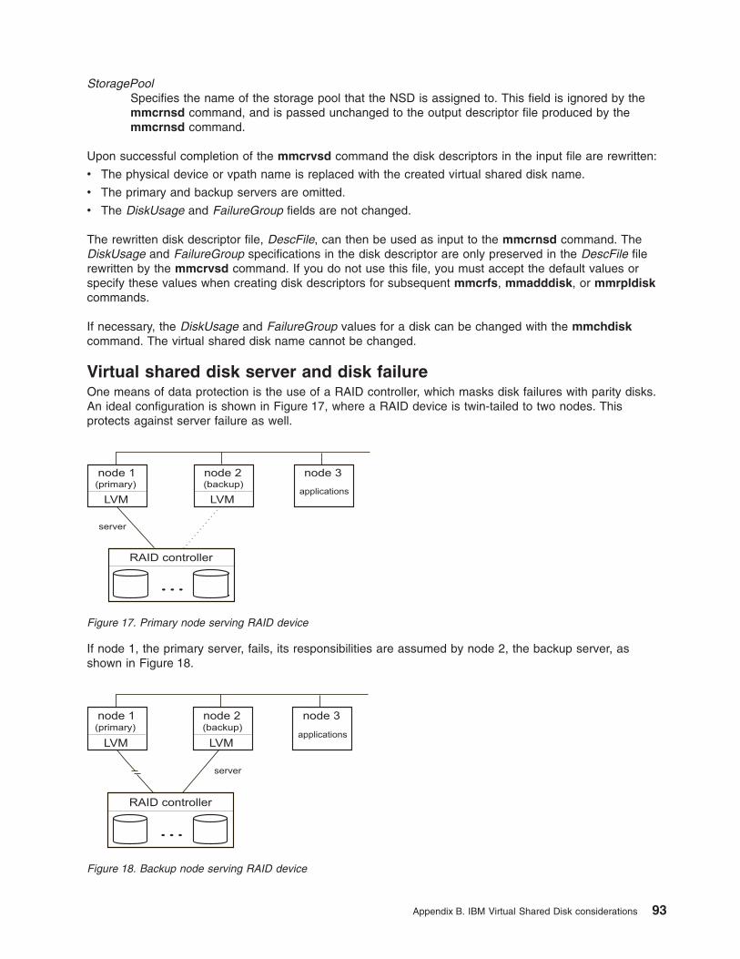
StoragePool
Specifies the name of the storage pool that the NSD is assigned to. This field is ignored by the
mmcrnsd command, and is passed unchanged to the output descriptor file produced by the
mmcrnsd command.
Upon successful completion of the mmcrvsd command the disk descriptors in the input file are rewritten:
v The physical device or vpath name is replaced with the created virtual shared disk name.
v The primary and backup servers are omitted.
v The DiskUsage and FailureGroup fields are not changed.
The rewritten disk descriptor file, DescFile, can then be used as input to the mmcrnsd command. The
DiskUsage and FailureGroup specifications in the disk descriptor are only preserved in the DescFile file
rewritten by the mmcrvsd command. If you do not use this file, you must accept the default values or
specify these values when creating disk descriptors for subsequent mmcrfs, mmadddisk, or mmrpldisk
commands.
If necessary, the DiskUsage and FailureGroup values for a disk can be changed with the mmchdisk
command. The virtual shared disk name cannot be changed.
Virtual shared disk server and disk failure
One means of data protection is the use of a RAID controller, which masks disk failures with parity disks.
An ideal configuration is shown in Figure 17, where a RAID device is twin-tailed to two nodes. This
protects against server failure as well.
If node 1, the primary server, fails, its responsibilities are assumed by node 2, the backup server, as
shown in Figure 18.
Figure 17. Primary node serving RAID device
Figure 18. Backup node serving RAID device
Appendix B. IBM Virtual Shared Disk considerations 93

If your disks are SAN-attached to the virtual shared disk servers, an ideal configuration is shown in
Figure 19.
Another means of data protection is through the use of concurrent virtual shared disks, as shown in
Figure 20. Concurrent disk access allows you to use multiple servers to satisfy disk requests by taking
advantage of the concurrent disk access environment supplied by AIX. For further information regarding
concurrent virtual shared disks, see the Managing Shared Disks manual for your environment:
v Reliable Scalable Cluster Technology: Managing Shared Disks
You can also protect your file system against disk failure by mirroring data at the logical volume manager
(LVM) level, writing the data twice to two different disks. The addition of twin-tailed disks to such a
configuration adds protection against server failure by allowing the IBM Recoverable Virtual Shared Disk
program to route requests through a backup server.
High Performance Switch
RAID controller/ESS
FC switch 2FC switch 1
node 2secondary vsd server
node 3vsd client
node 1primary vsd server
Figure 19. RAID/ESS Controller multi-tailed to the primary and secondary virtual shared disk servers
Figure 20. Concurrent node serving device
94 GPFS: Concepts, Planning, and Installation Guide
Appendix C. Considerations for GPFS applications
Application design should take into consideration:
v “Exceptions to Open Group technical standards”
v “Determining if a file system is controlled by GPFS”
v “GPFS exceptions and limitations to NFS V4 ACLs” on page 96
Exceptions to Open Group technical standards
GPFS is designed so that most applications written to The Open Group technical standard for file system
calls can access GPFS data with no modification, however, there are some exceptions.
Applications that depend on exact reporting of changes to the following fields returned by the stat() call
may not work as expected:
1. exact mtime
2. mtime
3. ctime
4. atime
Providing exact support for these fields would require significant performance degradation to all
applications executing on the system. These fields are guaranteed accurate when the file is closed.
These values will be accurate on a node right after it accesses or modifies a file, but may not be accurate
for a short while when a file is accessed or modified on some other node.
If ’exact mtime’ is specified for a file system (using the mmcrfs or mmchfs commands with the -E yes
flag), the mtime and ctime values are always correct by the time the stat() call gives its answer. If ’exact
mtime’ is not specified, these values will be accurate after a couple of minutes, to allow the
synchronization daemons to propagate the values to all nodes. Regardless of whether ’exact mtime’ is
specified, the atime value will be accurate after a couple of minutes, to allow for all the synchronization
daemons to propagate changes.
Alternatively, you may use the GPFS calls, gpfs_stat() and gpfs_fstat() to return exact mtime and atime
values.
The delayed update of the information returned by the stat() call also impacts system commands which
display disk usage, such as du or df. The data reported by such commands may not reflect changes that
have occurred since the last sync of the file system. For a parallel file system, a sync does not occur until
all nodes have individually synchronized their data. On a system with no activity, the correct values will be
displayed after the sync daemon has run on all nodes.
Determining if a file system is controlled by GPFS
A file system is controlled by GPFS if the f_type field in the statfs structure returned from a statfs() or
fstatfs() call has the value 0x47504653, which is the ASCII characters ’GPFS’.
This constant is in the gpfs.h file, with the name GPFS_SUPER_MAGIC. If an application includes
gpfs.h, it can compare f_type to GPFS_SUPER_MAGIC to determine if the file system is controlled by
GPFS.
© Copyright IBM Corp. 1998, 2006 95

GPFS exceptions and limitations to NFS V4 ACLs
GPFS has the following exceptions and limitations to the NFS V4 ACLs:
1. Alarm type ACL entries are not supported.
2. Audit type ACL entries are not supported.
3. Inherit entries (FileInherit and DirInherit) are always propagated to all child subdirectories. The NFS
V4 ACE4_NO_PROPAGATE_INHERIT_ACE flag is not supported.
4. Although the NFS V4 ACL specification provides separate controls for WRITE and APPEND, GPFS
will not differentiate between the two. Either both must be specified, or neither can be.
5. Similar to WRITE and APPEND, NFS V4 allows for separate ADD_FILE and ADD_SUBDIRECTORY
controls. In most cases, GPFS will allow these controls to be specified independently. In the special
case where the file system object is a directory and one of its ACL entries specifies both FileInherit
and DirInherit flags, GPFS cannot support setting ADD_FILE without ADD_SUBDIRECTORY (or the
other way around). When this is intended, we suggest creating separate FileInherit and DirInherit
entries.
6. Some types of access for which NFS V4 defines controls do not currently exist in GPFS. For these,
ACL entries will be accepted and saved, but since there is no corresponding operation they will have
no effect. These include READ_NAMED, WRITE_NAMED, and SYNCHRONIZE.
7. AIX requires that READ_ACL and WRITE_ACL always be granted to the object owner. Although this
contradicts NFS Version 4 Protocol, it is viewed that this is an area where users would otherwise
erroneously leave an ACL that only privileged users could change. Since ACLs are themselves file
attributes, READ_ATTR and WRITE_ATTR are similarly granted to the owner. Since it would not
make sense to then prevent the owner from accessing the ACL from a non-AIX node, GPFS has
implemented this exception everywhere.
8. AIX does not support the use of special name values other than owner@, group@, and everyone@.
Therefore, these are the only valid special name for use in GPFS NFS V4 ACLs as well.
9. NFS V4 allows ACL entries that grant users (or groups) permission to change the owner or owning
group of the file (for example, with the chown command). For security reasons, GPFS now restricts
this so that non-privileged users may only chown such a file to themselves (becoming the owner) or
to a group that they are a member of.
10. GPFS does not support NFS V4 exporting GPFS file systems from Linux nodes. NFS V3 is
acceptable.
For more information about GPFS ACLs and NFS export, see Managing GPFS access control lists and
NFS export in General Parallel File System: Administration and Programming Reference.
96 GPFS: Concepts, Planning, and Installation Guide

Notices
This information was developed for products and services offered in the U.S.A.
IBM may not offer the products, services, or features discussed in this document in other countries.
Consult your local IBM representative for information on the products and services currently available in
your area. Any reference to an IBM product, program, or service is not intended to state or imply that only
IBM’s product, program, or service may be used. Any functionally equivalent product, program, or service
that does not infringe any of IBM’s intellectual property rights may be used instead. However, it is the
user’s responsibility to evaluate and verify the operation of any non-IBM product, program, or service.
IBM may have patents or pending patent applications covering subject matter described in this document.
The furnishing of this document does not give you any license to these patents. You can send license
inquiries, in writing, to:
IBM Director of Licensing
IBM Corporation
North Castle Drive
Armonk, NY 10504-1785
USA
For license inquiries regarding double-byte (DBCS) information, contact the IBM Intellectual Property
Department in your country or send inquiries, in writing, to:
IBM World Trade Asia Corporation
Licensing
2-31 Roppongi 3-chome, Minato-ku
Tokyo 106, Japan
The following paragraph does not apply to the United Kingdom or any other country where such provisions
are inconsistent with local law:
INTERNATIONAL BUSINESS MACHINES CORPORATION PROVIDES THIS PUBLICATION “AS IS”
WITHOUT WARRANTY OF ANY KIND, EITHER EXPRESS OR IMPLIED, INCLUDING, BUT NOT
LIMITED TO, THE IMPLIED WARRANTIES OF NON-INFRINGEMENT, MERCHANTABILITY OR FITNESS
FOR A PARTICULAR PURPOSE. Some states do not allow disclaimer of express or implied warranties in
certain transactions, therefore, this statement may not apply to you.
This information could include technical inaccuracies or typographical errors. Changes are periodically
made to the information herein; these changes will be incorporated in new editions of the publication. IBM
may make improvements and/or changes in the product(s) and/or the program(s) described in this
publication at any time without notice.
Any references in this information to non-IBM Web sites are provided for convenience only and do not in
any manner serve as an endorsement of those Web sites. The materials at those Web sites are not part of
the materials for this IBM product and use of those Web sites is at your own risk.
IBM may use or distribute any of the information you supply in any way it believes appropriate without
incurring any obligation to you.
Licensees of this program who wish to have information about it for the purpose of enabling: (i) the
exchange of information between independently created programs and other programs (including this one)
and (ii) the mutual use of the information which has been exchanged, should contact:
IBM Corporation
Intellectual Property Law
Mail Station P300
© Copyright IBM Corp. 1998, 2006 97

2455 South Road,
Poughkeepsie, NY 12601-5400
USA
Such information may be available, subject to appropriate terms and conditions, including in some cases,
payment or a fee.
The licensed program described in this document and all licensed material available for it are provided by
IBM under terms of the IBM Customer Agreement, IBM International Program License Agreement or any
equivalent agreement between us.
This information contains examples of data and reports used in daily business operations. To illustrate
them as completely as possible, the examples include the names of individuals, companies, brands, and
products. All of these names are fictitious and any similarity to the names and addresses used by an
actual business enterprise is entirely coincidental.
COPYRIGHT LICENSE:
This information contains sample application programs in source language, which illustrates programming
techniques on various operating platforms. You may copy, modify, and distribute these sample programs in
any form without payment to IBM, for the purposes of developing, using, marketing or distributing
application programs conforming to the application programming interface for the operating platform for
which the sample programs are written. These examples have not been thoroughly tested under all
conditions. IBM, therefore, cannot guarantee or imply reliability, serviceability, or function of these
programs. You may copy, modify, and distribute these sample programs in any form without payment to
IBM for the purposes of developing, using, marketing, or distributing application programs conforming to
the application programming interfaces for the operating platform for which the sample programs are
written. These examples have not been thoroughly tested under all conditions. IBM, therefore, cannot
guarantee or imply reliability, serviceability, or function of these programs.
If you are viewing this information softcopy, the photographs and color illustrations may not appear.
Trademarks
The following terms are trademarks of the International Business Machines Corporation in the United
States or other countries or both:
v AIX
v AIX 5L
v Eserver
v Enterprise Storage Server
v IBM
v IBMLink
v LoadLeveler
v pSeries
v POWER
v RS/6000
v Redbook
v SANergy
v SP
v System p5
v System Storage
v Tivoli
98 GPFS: Concepts, Planning, and Installation Guide

v TotalStorage
v xSeries
Intel®, Intel Inside® (logos), MMX and Pentium® are trademarks of Intel Corporation in the United States,
other countries, or both.
Java and all Java-based trademarks and logos are trademarks or registered trademarks of Sun
Microsystems, Inc. in the United States, other countries, or both.
Linux is a registered trademark of Linus Torvalds in the United States, other countries, or both.
Red Hat, the Red Hat “Shadow Man” logo, and all Red Hat-based trademarks and logos are trademarks or
registered trademarks of Red Hat, Inc., in the United States and other countries.
UNIX is a registered trademark of the Open Group in the United States and other countries.
Other company, product, and service names may be the trademarks or service marks of others.
Notices 99

100 GPFS: Concepts, Planning, and Installation Guide

Glossary
This glossary defines technical terms and
abbreviations used in GPFS documentation. If you
do not find the term you are looking for, refer to
the index of the appropriate book or view the IBM
Glossary of Computing Terms, located on the
Internet at: w3.ibm.com/standards/terminology.
B
backup NSD server. A node designated to perform
NSD disk access functions in the event that the primary
NSD server fails.
block utilization. The measurement of the percentage
of used subblocks per allocated blocks.
C
cluster. A loosely-coupled collection of independent
systems (nodes) organized into a network for the
purpose of sharing resources and communicating with
each other. (See also “GPFS cluster” on page 103).
cluster configuration data files. The configuration
data that is stored on the cluster configuration servers.
configuration manager. The node that selects file
system managers and determines whether quorum
exists. The oldest continuously operating node in the file
system group is automatically assigned as the
configuration manager.
control data structures. Data structures needed to
manage file data and metadata cached in memory.
Control data structures include hash tables and link
pointers for finding cached data; lock states and tokens
to implement distributed locking; and various flags and
sequence numbers to keep track of updates to the
cached data.
D
Data Management Application Program Interface
(DMAPI). The interface defined by the Open Group’s
XDSM standard as described in the publication System
Management: Data Storage Management (XDSM) API
Common Application Environment (CAE) Specification
C429, The Open Group ISBN 1-85912-190-X.
deadman switch timer. A kernel timer that ensures
that a node that has lost its disk lease and has
outstanding I/O requests cannot complete those
requests (and risk causing file system corruption). This
is achieved by panicking the kernel.
disk descriptor. A disk descriptor defines how a disk
is to be used within a file system. Each descriptor
supplied to the mmcrfs command must be in the form
(second, third and sixth fields reserved):
DiskName:::DiskUsage:FailureGroup::StoragePool
Each descriptor supplied to the mmcrnsd command
must be in the form:
DiskName:PrimaryServer:BackupServer:DiskUsage:
FailureGroup:DesiredName:StoragePool
DiskName
The block device name appearing in /dev for
the disk you want to define as an NSD.
Examples of disks accessible through a block
device are SAN-attached disks or virtual
shared disks. If a PrimaryServer node is
specified, DiskName must be the /dev name
for the disk device on the primary NSD server
node. Use the GPFS FAQ link at
http://publib.boulder.ibm.com/infocenter/clresctr/index.jsp?topic=/com.ibm.cluster.infocenter.doc/library.html for the latest supported disk types.
Note that GPFS provides some helper
commands to ease configuration of /dev disk
devices. For instance the mmcrvsd command
can configure a virtual shared disk and make it
accessible to nodes connected over a high
performance switch. The output disk descriptor
file from an mmcrvsd command can be used
as input to the mmcrnsd command since the
virtual shared disk names enumerated in that
file will appear as /dev block devices on switch
attached nodes.
PrimaryServer
The name of the primary NSD server node.
If this field is omitted, the disk is assumed to
be directly attached to all nodes in the cluster.
BackupServer
The name of the backup NSD server node.
If the PrimaryServer has been specified and
this field is omitted, it is assumed you do not
want failover in the event the PrimaryServer
fails. If a PrimaryServer has not been specified,
this field must also be omitted.
Disk Usage
What is to be stored on the disk:
dataAndMetadata
Indicates that the disk contains both
data and metadata. This is the default.
dataOnly
Indicates that the disk contains data
and does not contain metadata.
© Copyright IBM Corp. 1998, 2006 101

metadataOnly
Indicates that the disk contains
metadata and does not contain data.
descOnly
Indicates that the disk contains no
data and no metadata. Such a disk is
used solely to keep a copy of the file
system descriptor, and can be used
as a third failure group in certain
disaster recovery configurations.
FailureGroup
A number identifying the failure group to which
this disk belongs. All disks that are either
attached to the same adapter or NSD server
have a common point of failure and should
therefore be placed in the same failure group.
GPFS uses this information during data and
metadata placement to assure that no two
replicas of the same block become unavailable
due to a single failure. You can specify any
value from -1 (where -1 indicates that the disk
has no point of failure in common with any
other disk) to 4000. If you specify no failure
group, the value defaults to the primary NSD
server node number plus 4000. For disk
directly attached to all nodes in the cluster the
value defaults to -1.
DesiredName
Specify the name you desire for the NSD to be
created. This name must not already be used
by another GPFS disk name, and it must not
begin with the reserved string 'gpfs'. If a
desired name is not specified, the NSD is
assigned a name according to the convention:
gpfsNNnsd
where NN is a unique non negative
integer not used in any prior NSD.
These global disk names must be
subsequently used on all GPFS
commands. GPFS commands, other
than the mmcrnsd and mmcrvsd
commands, do not accept physical
disk device names.
StoragePool
Specifies the storage pool to which the disk is
to be assigned. If this name is not provided,
the default is system.
disposition. The session to which a data management
event is delivered. An individual disposition is set for
each type of event from each file system.
disk leasing. A method for controlling access to
storage devices from multiple host systems. Any host
that wants to access a storage device configured to use
disk leasing registers for a lease; in the event of a
perceived failure, a host system can deny access,
preventing I/O operations with the storage device until
the preempted system has reregistered.
domain. (1) A set of network resources (such as
applications and printers, for example) for a group of
users. A user logs in to the domain to gain access to
the resources, which could be located on a number of
different servers in the network. (2) A group of server
and client machines that exist in the same security
structure. (3) A group of computers and devices on a
network that are administered as a unit with common
rules and procedures. Within the Internet, a domain is
defined by its Internet Protocol (IP) address. All devices
that share a common part of the IP address are said to
be in the same domain.
E
event. The encapsulated data that is sent as a result
of an occurrence, or situation, in the system.
F
failback. Cluster recovery from failover following
repair. See also failover.
failover. (1) The process of transferring all control of
the ESS to a single cluster in the ESS when the other
cluster in the ESS fails. See also cluster. (2) The routing
of all transactions to a second controller when the first
controller fails. See also cluster. (3) The assumption of
file system duties by another node when a node fails.
failure group. A collection of disks that share common
access paths or adapter connection, and could all
become unavailable through a single hardware failure.
fileset. A hierarchical grouping of files managed as a
unit for balancing workload across a cluster.
file-management policy. A set of policy rules used to
manage file migration and deletion.
file-placement policy. A set of policy rules used to
determine the initial placement of a newly created file.
file system descriptor. A data structure containing
key information about a file system. This information
includes the disks assigned to the file system (stripe
group), the current state of the file system, and pointers
to key files such as quota files and log files.
file system descriptor quorum. The number of disks
needed in order to write the file system descriptor
correctly.
file system manager. The provider of services for all
the nodes using a single file system. A file system
manager processes changes to the state or description
of the file system, controls the regions of disks that are
allocated to each node, and controls token management
and quota management.
102 GPFS: Concepts, Planning, and Installation Guide

fragment. The space allocated for an amount of data
too small to require a full block, consisting of one or
more subblocks.
G
GPFS cluster. A cluster of nodes defined as being
available for use by GPFS file systems.
GPFS portability layer . The interface module that
each installation must build for its specific hardware
platform and Linux distribution.
GPFS recovery log. A file that contains a record of
metadata activity, and exists for each node of a cluster.
In the event of a node failure, the recovery log for the
failed node is replayed, restoring the file system to a
consistent state and allowing other nodes to continue
working.
I
ill-placed file. A file assigned to one storage pool, but
having some or all of its data in a different storage pool.
ill-replicated file. A file with contents that are not
correctly replicated according to the desired setting for
that file. This situation occurs in the interval between a
change in the file's replication settings or suspending
one of its disks, and the restripe of the file.
indirect block. A block containing pointers to other
blocks.
IBM Virtual Shared Disk. The subsystem that allows
application programs running on different nodes access
a raw logical volume as if it were local to each node. In
actuality, the logical volume is local to only one of the
nodes (the server node).
inode. The internal structure that describes the
individual files in the file system. There is one inode for
each file.
J
journaled file system (JFS). A technology designed
for high-throughput server environments, key to running
intranet and other high-performance e-business file
servers.
junction.
A special directory entry that connects a name in a
directory of one fileset to the root directory of another
fileset.
L
logical volume. A collection of physical partitions
organized into logical partitions all contained in a single
volume group. Logical volumes are expandable and can
span several physical volumes in a volume group.
Logical Volume Manager (LVM). A set of system
commands, library routines, and other tools that allow
the user to establish and control logical volume (LVOL)
storage. The LVM maps data between the logical view
of storage space and the physical disk drive module
(DDM).
M
metadata. A data structures that contain access
information about file data. These include: inodes,
indirect blocks, and directories. These data structures
are not accessible to user applications.
metanode. The one node per open file that is
responsible for maintaining file metadata integrity. In
most cases, the node that has had the file open for the
longest period of continuous time is the metanode.
mirroring. The process of writing the same data to
multiple disks at the same time. The mirroring of data
protects it against data loss within the database or
within the recovery log.
multi-tailed. A disk connected to multiple nodes.
N
namespace. Space reserved by a file system to
contain the names of its objects.
Network File System (NFS). A protocol, developed by
Sun Microsystems, Incorporated, that allows any host in
a network to gain access to another host or netgroup
and their file directories.
Network Shared Disk (NSD). A component for
cluster-wide disk naming and access. All disks utilized
by GPFS must first be given a cluster-wide NSD name.
NSD volume ID. A unique 16 digit hex number that is
used to identify and access all NSDs.
node. An individual operating-system image within a
cluster. Depending on the way in which the computer
system is partitioned, it may contain one or more nodes.
node descriptor. A node descriptor defines how a
node is to be used within GPFS.
Each node descriptor for a GPFS cluster must be in the
form:
NodeName:NodeDesignations:AdminNodeName
NodeName
The hostname or IP address of the node.
designation
An optional, ’-’ separated list of node roles.
Glossary 103
v manager | client – Indicates whether a
node is part of the pool of nodes from which
configuration and file system managers are
selected. The special functions of the file
system manager consume extra processing
time. The default is to not have the node
included in the pool.
In general, small systems do not need
multiple nodes dedicated for the file system
manager. However, if you are running large
parallel jobs, threads scheduled to a node
performing these functions may run slower.
As a guide, in a large system there should
be one file system manager node for each
file system.
v quorum | nonquorum – This designation
specifies whether or not the node should be
included in the pool of nodes from which
quorum is derived.
AdminNodeName
An optional field that consists of a node name
to be used by the administration commands to
communicate between nodes. If
AdminNodeName is not specified, the
NodeName value is used.
node number. The node number is generated and
maintained by GPFS as the cluster is created and as
nodes are added to or deleted from the cluster.
node quorum. The minimum number of nodes that
must be running in order for the daemon to start.
node quorum with tiebreaker disks. Node quorum
with tiebreaker disks allows you to run with as little as
one quorum node available as long as you have access
to a majority of the quorum disks. Switching to quorum
with tiebreaker disks is accomplished by indicating a list
of one or three disks to use on the tiebreakerDisks
parameter on the mmchconfig command.
non-quorum node. A node in a cluster that is not
counted for the purposes of quorum determination.
P
policy. A list of file-placement and service-class rules
that define characteristics and placement of files.
Several policies can be defined within the configuration,
but only one policy set is active at one time.
policy rule. A programming statement within a policy
that defines a specific action to be preformed.
pool. A group of resources with similar characteristics
and attributes.
portability. The ability of a programming language to
compile successfully on different operating systems
without requiring changes to the source code.
primary GPFS cluster configuration server. In a
GPFS cluster, the node chosen to maintain the GPFS
cluster configuration data.
primary NSD server. A node designated to perform
NSD disk access functions. Nodes not directly attached
to a disk access it using the primary NSD server.
private IP address. A IP address used to
communicate on a private network.
public IP address. A IP address used to communicate
on a public network.
Q
quorum node. A node in the cluster that is counted to
determine whether a quorum exists.
quota. The amount of disk space and number of
inodes assigned as upper limits for a specified user,
group of users, or fileset.
quota management. The allocation of disk blocks to
the other nodes writing to the file system and
comparison of the allocated space to quota limits at
regular intervals.
R
Redundant Array of Independent Disks (RAID). A
collection of two or more disk physical drives that
present to the host an image of one or more logical disk
drives. In the event of a single physical device failure,
the data can be read or regenerated from the other disk
drives in the array due to data redundancy.
recovery. The process of restoring access to file
system data when a failure has occurred. Recovery can
involve reconstructing data or providing alternative
routing through a different server.
replication. The process of maintaining a defined set
of data in more than one location. Replication involves
copying designated changes for one location (a source)
to another (a target), and synchronizing the data in both
locations.
rule. A list of conditions and actions that are triggered
when certain conditions are met. Conditions include
attributes about an object (file name, type or extension,
dates, owner, and groups), the requesting client, and
the container name associated with the object.
S
SAN-attached. Disks that are physically attached to all
nodes in the cluster using Serial Storage Architecture
(SSA) connections or using fibre channel switches
SANergy. See Tivoli SANergy.
104 GPFS: Concepts, Planning, and Installation Guide

secondary GPFS cluster configuration server. In a
GPFS cluster, the backup server node for the GPFS
cluster configuration data (see “cluster configuration
data” on page 101). The secondary GPFS cluster
configuration server assumes responsibility for
maintaining GPFS cluster configuration data, in the
event that the primary GPFS cluster configuration server
fails.
Secure Hash Algorithm digest (SHA digest). A
character string used to identify a key registered with
either the mmauth or mmremotecluster command.
Serial Storage Architecture (SSA). An American
National Standards Institute (ANSI) standard,
implemented by IBM, for a high-speed serial interface
that provides point-to-point connection for peripherals,
such as storage arrays.
session failure. The loss of all resources of a data
management session due to the failure of the daemon
on the session node.
session node. The node on which a data
management session was created.
Small Computer Systems Interface (SCSI). An
ANSI-standard electronic interface that allows personal
computers to communicate with peripheral hardware,
such as disk drives, tape drives, CD_ROM drives,
printers, and scanners faster and more flexibly than
previous interfaces.
snapshot. A copy of changed data in the active files
and directories of a file system with the exception of the
i-node number, which is changed to allow application
programs to distinguish between the snapshot and the
active files and directories.
source node. The node on which a data management
event is generated.
SSA. See Serial Storage Architecture.
stand-alone client. The node in a one-node cluster.
storage area network (SAN). A dedicated storage
network tailored to a specific environment, combining
servers, storage products, networking products,
software, and services.
storage pool. A grouping of storage space consisting
of volumes, logical unit numbers (LUNs), or addresses
that share a common set of administrative
characteristics.
stripe group. The set of disks comprising the storage
assigned to a file system.
striping. A storage process in which information is
split into blocks (a fixed amount of data) and the blocks
are written to (or read from) a series of disks in parallel.
subblock. The smallest unit of data accessible in an
I/O operation, equal to one thirty-second of a data
block.
system storage pool. A storage pool contains file
system control structures, reserved files, directories,
symbolic links, special devices, as well as the metadata
associated with regular files, including indirect blocks,
extended attributes, and so forth. The system storage
pool can also contain user data.
T
Tivoli SANergy. A product of IBM Tivoli, that delivers
shared data access at the speed of a storage area
network (SAN), using fibre channel, Small computer
system interface (SCSI), or iSCSI. Using standard
networks and file systems, SANergy provides multiple
computers with the power to dynamically share file and
data access on SAN-based storage.
token management. A system for controlling file
access in which each application performing a read or
write operation is granted some form of access to a
specific block of file data. Token management provides
data consistency and controls conflicts.
Token management has two components: the token
manager server, and the token management function.
token management function. Requests tokens from
the token management server, and is located on each
cluster node.
token management server. Controls tokens relating
to the operation of the file system, and is located at the
file system manager node.
twin-tailing. To connect a disk to multiple nodes
U
user storage pool. A storage pool containing the
blocks of data that make up user files.
V
virtual file system (VFS). A remote file system that
has been mounted so that it is accessible to the local
user.
virtual shared disk. See “IBM Virtual Shared Disk” on
page 103.
virtual node (vnode). The structure that contains
information about a file system object in an virtual file
system (VFS).
Glossary 105

106 GPFS: Concepts, Planning, and Installation Guide
Bibliography
This bibliography contains references for:
v GPFS publications
v Eserver Cluster 1600 publications
v AIX publications
v Tivoli publications
v Storage references
v Disaster recovery
v IBM RedBooks
v White papers
v Useful Web sites
v Non-IBM publications that discuss parallel computing and other topics related to GPFS
All IBM publications are also available from the IBM Publications Center at www.ibmcom/shop/publications/order
GPFS publications
You may download, view, search, and print the supporting documentation for the GPFS program product in
the following ways:
1. In PDF format:
v On the World Wide Web at publib.boulder.ibm.com/infocenter/clresctr/topic/com.ibm.cluster.gpfs.doc/gpfsbooks.html
v From the IBM Publications Center at www.ibm.com/shop/publications/order
2. In HTML format at publib.boulder.ibm.com/infocenter/clresctr/topic/com.ibm.cluster.gpfs.doc/gpfsbooks.html
3. For the latest GPFS documentation updates refer to the GPFS Information Center
athttp://publib.boulder.ibm.com/infocenter/clresctr/index.jsp?topic=/com.ibm.cluster.infocenter.doc/library.html
The GPFS library includes:
v General Parallel File System: Concepts, Planning, and Installation Guide, GA76-0413
v General Parallel File System: Administration and Programming Reference, SA23-2221
v General Parallel File System: Advanced Administration Guide, SC23-5182
v General Parallel File System: Problem Determination Guide, GA76-0415
v General Parallel File System: Data Management API Guide, GA76-0414
To view the GPFS PDF publications, you need access to either the Adobe Acrobat Reader or the xpdf
package available with the Red Hat® Linux distribution. The Acrobat Reader is shipped with the AIX 5L
Bonus Pack and is also freely available for downloading from the Adobe web site at www.adobe.com.
Since the GPFS documentation contains cross-book links, if you choose to download the PDF files they
should all be placed in the same directory and the files should not be renamed.
To view the GPFS HTML publications, you need access to an HTML document browser.
In order to use the GPFS man pages the gpfsdocs file set must first be installed. In the General Parallel
File System: Concepts, Planning, and Installation Guide:
v For Linux nodes, see Installing the GPFS man pages
© Copyright IBM Corp. 1998, 2006 107

v For AIX nodes, see Installing the GPFS man pages
Eserver Cluster 1600 hardware publications
For a current list of Eserver Cluster 1600 hardware publications, see http://publib.boulder.ibm.com/infocenter/clresctr/index.jsp?topic=/com.ibm.cluster.infocenter.doc/library.html
AIX publications
For the latest information on:
v AIX 5L Version 5.3 and related products at publib.boulder.ibm.com/infocenter/pseries/index.jsp
Tivoli publications
v You can view or download the TSM for AIX documentation at: publib.boulder.ibm.com/tividd/td/IBMStorageManagerforAIX5.1.html
v You can view or download the TSM for Linux documentation at: publib.boulder.ibm.com/tividd/td/IBMTivoliStorageManagerforLinux5.1.html
v You can view or download the TSM UNIX documentation at: publib.boulder.ibm.com/tividd/td/IBMTivoliStorageManagerClient5.1.5.html
– Tivoli Storage Manager for UNIX Backup-Archive Clients Installation and User’s Guide
v You can view or download the TSM message documentation at: publib.boulder.ibm.com/tividd/td/IBMStorageManagerMessages5.1.html
v You can view or download the Tivoli SANergy documentation at: publib.boulder.ibm.com/tividd/td/SANergy2.2.4.html
v You can view or download IBM Tivoli Workload Scheduler LoadLeveler® for AIX (LoadLeveler)
documentation at publib.boulder.ibm.com/infocenter/clresctr/topic/com.ibm.cluster.loadl.doc/llbooks.html
Storage references
Various references include:
v IBM System Storage™ and TotalStorage at http://www-03.ibm.com/servers/storage/
v IBM TotalStorage DS4000 series at ssdweb01.storage.ibm.com/disk/fastt/
v IBM Subsystem Device Driver support at www.ibm.com/server/storage/support/software/sdd.html
v IBM Enterprise Storage Server documentation at www.storage.ibm.com/hardsoft/products/ess/refinfo.htm
Disaster recovery references
v IBM Enterprise Storage Server at www.redbooks.ibm.com/redbooks/pdfs/sg245465.pdf
v IBM TotalStorage Enterprise Storage Server User’s Guide at publibfp.boulder.ibm.com/epubs/pdf/f2bug05.pdf
v IBM TotalStorage Enterprise Storage Server Implementing ESS Copy Services in Open Environments at
www.redbooks.ibm.com/redbooks/pdfs/sg245757.pdf
v IBM TotalStorage Enterprise Storage Server Web Interface User’s Guide, SC26-7448, at
publibfp.boulder.ibm.com/epubs/pdf/f2bui05.pdf
v IBM Enterprise Storage Server Command-Line Interfaces User’s Guide, SC26-7994, at
publibfp.boulder.ibm.com/epubs/pdf/f2bcli04.pdf
v ESS Copy Services Tasks: A Possible Naming Convention at publib-b.boulder.ibm.com/Redbooks.nsf/RedbookAbstracts/tips0289.html?Open
v Valid Combinations of ESS Copy Services at publib-b.boulder.ibm.com/Redbooks.nsf/RedbookAbstracts/tips0311.html?Open
108 GPFS: Concepts, Planning, and Installation Guide

v Connectivity Guidelines for Synchronous PPRC at publib-b.boulder.ibm.com/Redbooks.nsf/RedbookAbstracts/tips0211.html?Open
v A Disaster Recovery Solution Selection Methodology at www.redbooks.ibm.com/redpapers/pdfs/redp3847.pdf
v IBM TotalStorage Solutions for Disaster Recovery, SG24-6547, at www.redbooks.ibm.com/redbooks/pdfs/sg246547.pdf
v Seven Tiers of Disaster Recovery at publib-b.boulder.ibm.com/Redbooks.nsf/RedbookAbstracts/tips0340.html?Open
IBM Redbooks
IBM’s International Technical Support Organization (ITSO) has published a number of Redbooks™. For a
current list, see the ITSO Web site at www.ibm.com/redbooks
White papers
A primer for GPFS for AIX 5L at www.ibm.com/servers/eserver/pseries/software/whitepapers/gpfs_primer.html
A technical introduction to GPFS for AIX 5L at www.ibm.com/servers/eserver/pseries/software/whitepapers/gpfs_intro.html
IBM Eserver pSeries white papers at www.ibm.com/servers/eserver/pseries/library/wp_systems.html
Clustering technology white papers at www.ibm.com/servers/eserver/clusters/library/wp_aix_lit.html
AIX white papers at www.ibm.com/servers/eserver/clusters/library/wp_aix_lit.html
White paper and technical reports home page at www.ibm.com/servers/eserver/pseries/library/wp_systems.html
Useful Web sites
Linux at IBM at www.ibm.com/software/is/mp/linux/software
Clusters at IBM www.ibm.com/eserver/clusters
GPFS for Linux at www.ibm.com/servers/eserver/clusters/software/gpfs.html
GPFS for AIX at www.ibm.com/servers/eserver/pseries/software/sp/gpfs.html
xSeries Intel processor-based servers at www.pc.ibm.com/us/eserver/xseries/
UNIX servers: System p5, Eserver p5 and pSeries at www.ibm.com/servers/eserver/pseries/
Red Hat at www.redhat.com/
SuSE at www.suse.com/
Myrinet at www.myri.com/
Fibre Channel at www.fibrechannel.org/
The Linux documentation project at www.tldp.org/
Bibliography 109
RPM at www.rpm.org/
The Internet Engineering Task Force at www.ietf.org/
The Open Group at www.opengroup.org/
The Linux Kernel Archives at www.kernel.org/
OpenSSH at www.openssh.com
The OpenSSL Project at www.openssl.org
Non-IBM publications
Here are some non-IBM publications that you may find helpful:
v Almasi, G., Gottlieb, A., Highly Parallel Computing, Benjamin-Cummings Publishing Company, Inc., 2nd
edition, 1994.
v Foster, I., Designing and Building Parallel Programs, Addison-Wesley, 1995.
v Gropp, W., Lusk, E., Skjellum, A., Using MPI, The MIT Press, 1994.
v Message Passing Interface Forum, MPI: A Message-Passing Interface Standard, Version 1.1, University
of Tennessee, Knoxville, Tennessee, June 6, 1995.
v Message Passing Interface Forum, MPI-2: Extensions to the Message-Passing Interface, Version 2.0,
University of Tennessee, Knoxville, Tennessee, July 18, 1997.
v Ousterhout, John K., Tcl and the Tk Toolkit, Addison-Wesley, Reading, MA, 1994, ISBN 0-201-63337-X.
v Pfister, Gregory, F., In Search of Clusters, Prentice Hall, 1998.
v System Management: Data Storage Management (XDSM) API Common Applications Environment
(CAE) Specification C429, The Open Group, ISBN 1-85912-190-X. Available online in HTML from The
Open Group’s Web site at www.opengroup.org/.
110 GPFS: Concepts, Planning, and Installation Guide
Index
Special characters/tmp/mmfs
collecting problem determination data in 43
Aaccess control lists (ACLs)
file system authorization 35
access to file systemsaccess patterns of applications 64
simultaneous 4
adapterinvariant address requirement 15
administration commandsGPFS 6, 7, 81
AdminNodeName 81
AIXcommunication with GPFS 81
electronic license agreement 50
installation instructions for GPFS 49
installing GPFS 49
prerequisite software 49
allocation mapblock 76
inode 77
logging of 77
application programsaccess patterns 64
communicating with GPFS 81
applying maintenance levels to GPFS 59
atime 95
atime value 34
autoload attribute 25
automatic mountshared file system access 5
Bbacking up a file system
files created during 88
bandwidthincreasing aggregate 4
blockallocation map 76
size 34
buddy buffers 69
Ccache 78
GPFS token system’s affect on 63
GPFS usage 62
pageable memory for file attributes not in file
cache 62
pagepool 62
total number of different file cached at one time 62
Channel Bonding 64
cluster configuration data files/var/mmfs/gen/mmsdrfs file 87
content 87
coexistence considerations 58
collecting problem determination data 43
commandsdescription of GPFS commands 6
error communication 81
failure of 23
GPFS administration 81
mmadddisk 29
mmaddnode 81
mmbackup 88
mmchcluster 81
mmchconfig 79, 80
mmchdisk 85
mmcheckquota 38, 82
mmchfs 31
mmconfig 79
mmcrcluster 15, 21, 45, 49, 80, 81
mmcrfs 29, 31
mmcrnsd 27, 90
mmcrvsd 90, 93
mmdefedquota 37
mmdefquotaon 37
mmedquota 37, 38
mmfsck 77, 82, 85
mmlsdisk 31, 85
mmlsquota 38
mmmount 82
mmrepquota 38
mmrpldisk 29
mmstartup 25
operating system 81
processing 85
remote file copyrcp 24
remote shellrsh 24
communicationGPFS daemon to daemon 22
invariant address requirement 15
communications I/OAIX nodes 67
Linux nodes 66
compatibility considerations 59
concurrent virtual shared disks, use of 94
configurationfiles 87
flexibility in your GPFS cluster 5
of a GPFS cluster 21
configuration and tuning settingsaccess patterns 64
aggregate network interfaces 64
AIX settings 67
buddy buffers 69
clock synchronization 61
communications I/O 66, 67
© Copyright IBM Corp. 1998, 2006 111
configuration and tuning settings (continued)configuration file 25
default values 25
disk I/O 66, 67
general settings 61
GPFS files 7
GPFS helper threads 66
GPFS I/O 64, 67
GPFS pagepool 62
HPS 68
IBM Virtual Shared Disk 68
IP packet size 69
Jumbo Frames 66
Linux settings 65
monitoring GPFS I/O performance 61
SANergy 65
security 61
swap space 65
switch pool 68
TCP window 66
use with Oracle 69
configuration managerdescription 73
initialization of GPFS 81
considerations for GPFS applications 95
creating GPFS directory/tmp/gpfslpp on AIX nodes 50
/tmp/gpfslpp on Linux nodes 46
ctime 95
Ddaemon
communication 22
description of the GPFS daemon 7
memory 78
quorum requirement 73
starting 25
dataavailability 5
consistency of 5
guarding against failure of a path to a disk 20
recoverability 16
replication 35
data blockslogging of 77
recovery of 77
Data Management API (DMAPI)enabling 39
default quotasdescription 37
files 77
descOnly 31
device nameassigning 39
disaster recoveryuse of GPFS replication and failure groups 5
disk descriptor replica 30, 31
disksconsiderations 25
descriptor 28
disks (continued)disk descriptor 27
failure 19
file system descriptor 75
free space 26
I/O settings 66
I/O tuning parameters 67
media failure 86
mmcrfs command 33
NSD server configuration 9, 10
planning for virtual shared disks 89
recovery 85
releasing blocks 86
state of 85
storage area network 25
storage area network configuration 9
stripe group 75
usage 28, 31
usage verification 39
distributed tokens, managing 25
DMAPIcoexistence considerations 58
documentationinstalling man pages on AIX nodes 50
installing man pages on Linux nodes 47
obtaining 107
Eelectronic license agreement
AIX nodes 50
Linux nodes 46
estimated node count 36
EtherChannel 64
exceptions to Open Group technical standards 95
Ffailure
disk 19
Network Shared Disk server 19
node 16
failure group 31
failure groupschoosing 91
definition of 5
loss of 31
preventing loss of data access 19
use of 30
file system descriptor 31
failure groups 30
inaccessible 31
quorum 30
file system format 38
file system manageradministration command processing 81
command processing 85
communication with 81
description 73
mount of a file system 82
NSD creation considerations 29
112 GPFS: Concepts, Planning, and Installation Guide
file system manager (continued)quota management function 74
selection of 74
token management function 74
file systemsaccess patterns of applications 64
administrative state of 7, 87
authorization 35
backing up 88
block size 34
change device name 39
controlled by GPFS 95
creating 31
descriptor 75
device name 33
disk descriptor 33
disks belonging to an existing file system 39
enabling DMAPI 39
GPFS control 95
interacting with a GPFS file system 81
last time accessed 34
maximum number of 76
maximum number of files 36
maximum number of mounted files 76
maximum size supported 76
metadata 75
metadata integrity 75
migrating 38
mount options 37
mounting 5, 33, 38, 82
mountpoint 32
number of nodes mounted by 36
opening a file 82
quotas 37
reading a file 83
recoverability parameters 35
repairing 85
sample creation 39
shared access among clusters 3
simultaneous access 4
sizing 31
stripe group 75
time last modified 35
writing to a file 83
files/.rhosts 61
/etc/filesystems 87
/etc/fstab 87
/var/mmfs/etc/mmfs.cfg 87
/var/mmfs/gen/mmsdrfs 87
.mmbuControl 88
.mmbuPendingChgs 88
.mmbuPendingDels 88
.mmbuShadowCheck 88
.toc 50
consistency of data 5
fileset.quota 77
GPFS recovery logs 77
group.quota 77
inode 76
installation on AIX nodes 49
files (continued)installation on Linux nodes 45
maximum number of 36, 76
mmfslinux 8
structure within GPFS 75
user.quota 77
files systemsmaximum size 76
fragments, storage of files 34
FSDesc structure 30
GGPFS administration commands 79
GPFS administrative adapter port name 22
GPFS clustersadministration adapter port name 22
administration commands 81
architecture of GPFS 73
configuration data files 7
configuration file 25
configuration servers 23
creating 21
daemonstarting 25
daemon communication 79
definition of 9
heterogeneous clustersNSD server and virtual shared disk server
attached disks 11
NSD server attached disks 10
utilizing an HPS 10
homogenous clustersNSD server attached disks 9, 11
SAN-attached disks 9
introduction 3
naming 24
nodes in the cluster 22
operating environment 8
planning nodes 21
portability layer 48
recovery logscreation of 77
unavailable 86
requirements 12
server nodes 21
shared file system access 12
starting the GPFS daemon 25, 73
user ID domain 24
GPFS communications adapter port name 22
GPFS daemon communications 79
GPFS, installing over a network 50
grace period, quotas 37
Hhard limit, quotas 37
hardware requirements 15
helper threadstuning 66
Index 113

High Performance SwitchNSD creation consideration 27
HPSNSD creation consideration 27
tuning parameters 68
IIBM Recoverable Virtual Shared Disk 26
use of 89
IBM Virtual Shared Disktuning parameters 68
use of 89
indirect blocks 75, 77
indirection level 75
initialization of GPFS 81
inodeallocation file 76
allocation map 77
cache 78
logging of 77
usage 75, 85
installing GPFSover a network 50
installing GPFS on AIX nodescreating the GPFS directory 50
directions 50
electronic license agreement 50
existing GPFS files 51
files used during 49
man pages 50
procedures for 49
table of contents file 50
using Tivoli SANergy 51
verifying the GPFS installation 51
what to do before you install GPFS 49
installing GPFS on Linux nodesbuilding your GPFS portability layer 48
creating the GPFS directory 46
directions 47
electronic license agreement 46
files used during 45
License Acceptance Process (LAP) Tool 46
man pages 47
procedures for 45
remote command environment 46
verifying the GPFS installation 47
what to do before you install GPFS 45
invariant address adapterrequirement 15
IP addressprivate 80
public 80
IP packet size 69
IP_max_msg_size parameter 69
ipqmaxlen parameter 67
JJumbo Frames 66
Kkernel extensions 7
kernel memory 78
LLicense Acceptance Process (LAP) Tool 46
license inquiries 97
link aggregation 64
Linuxinstallation instructions for GPFS 45
installing GPFS 45
kernel requirement 15
prerequisite software 45
requirements 8
load balancing across disks 4
Mmaintenance levels of GPFS, applying 59
man pagesinstalling on AIX nodes 50
installing on Linux nodes 47
obtaining 107
managing distributed tokens 25
max_coalesce parameter 67
maxFilesToCache parameterdefinition 62
memory usage 79
maximum number of files 36
maxStatCache parameterdefinition 62
memory usage 79
memorycontrolling 62
swap space 65
usage 78
used to cache file data and metadata 63
metadata 75
disk usage to store 28
replication 35
metanode 75
migratingbefore you begin migration 53
completing the migration 56
reverting to the previous level of GPFS 56
to the new level of GPFS 53, 55
mmadddisk commandand rewritten disk descriptor file 29
mmaddnode 81
mmchcluster 81
mmchconfig 80
mmcrcluster 80, 81
mmcrfs commandand rewritten disk descriptor file 29
mmcrnsd command 27, 90
mmcrvsd command 90
mmlsdisk command 31
mmmount 82
114 GPFS: Concepts, Planning, and Installation Guide
mmrpldisk commandand rewritten disk descriptor file 29
mount options 37
mounting a file system 32, 33, 38, 82
mtime 95
mtime values 35
Multiple Path I/O (MPIO)utilizing 20
Nnetwork
communication within your cluster 4
Network File System (NFS)’deny-write open lock’ 33
access control lists 35
network installing GPFS 50
network interfaces 64
Network Shared Disk (NSD)backup server node 27
creation of 27
description 8
disk discovery 86
High Performance Switch consideration 27
HPS consideration 27
primary server node 27
SAN configuration 9
server configuration 9, 10
server disk considerations 25
server failure 19
server node considerations 29
NFS V4 ACLGPFS exceptions 96
special names 96
NFS V4 protocolGPFS exceptions 96
node quorumdefinition of 16
selecting nodes 18
node quorum with tiebreaker disksdefinition of 16
selecting nodes 18
nodesacting as special managers 73
configuration manager 73
descriptor form 22
designation as manager or client 23
estimating the number of 36
failure 16
file of nodes in the cluster for installation 45, 49
file system manager 73
file system manager selection 74
in a GPFS cluster 21
in the GPFS cluster 22
quorum 23
swap space 65
notices 97
OOpen Secure Sockets Layer (OpenSSL)
use in shared file system access 3
operating systemcalls 82
commands 81
OracleGPFS use with, tuning 69
Ppagepool parameter
affect on performance 84
in support of I/O 78
memory usage 78
usage 62
patent information 97
PATH environment variable 45, 49
performanceaccess patterns 64
aggregate network interfaces 64
disk I/O settings 66
monitoring GPFS I/O performance 4
monitoring using mmpon 61
pagepool parameter 84
setting maximum amount of GPFS I/O 64, 67
use of GPFS to improve 4
use of pagepool 78
planning considerationshardware requirements 15
recoverability 16
software requirements 15
portability layerbuilding 48
description 8
prefetchThreads parametertuning
on Linux nodes 66
use with Oracle 69
private IP address 80
programming specificationsAIX prerequisite software 49
Linux prerequisite software 45
verifying prerequisite software 45, 49
PTF support 59
public IP address 80
Qquorum
definition of 16
during node failure 16
enforcement 73
initialization of GPFS 81
selecting nodes 18
quotasdefault quotas 37
description 37
files 77
in a replicated system 37
Index 115

quotas (continued)mounting a file system with quotas enabled 38
role of file system manager node 74
system files 38
values reported in a replicated file system 37
Rrcp 24
read operationbuffer available 83
buffer not available 83
requirements 83
token management 83
recoverabilitydisk failure 19
disks 85
features of GPFS 5, 86
file systems 85
node failure 16
parameters 16
Redundant Array of Independent Disks (RAID)block size considerations 34
isolating metadata 28
preventing loss of data access 19
RAID5 performance 66
use with virtual shared disks 93
remote command environmentrcp 24
rsh 24
setting the 46
removing GPFS 71
repairing a file system 85
replicationaffect on quotas 37
description of 5
preventing loss of data access 19
requirementshardware 15
software 15
restripe see rebalance 113
rewritten disk descriptor fileuses of 29
root authority 61
rpoolsizeHPS 68
rsh 24
SSANergy see Tivoli SANergy 113
sanpshotscoexistence considerations 58
security 61
shared file system access 3
servicing your GPFS system 59
shared file system access 3
shared segments 78
sizing file systems 31
socket communications, use of 81
soft limit, quotas 37
softcopy documentation 47, 50
software requirements 15
spoolsizeHPS 68
standards, exceptions to 95
starting GPFS 25
stat cache 78
stat( ) system call 85
stat() system call 78
storage see memory 113
Storage Area Network (SAN)disk configuration 9
disk considerations 25
structure of GPFS 7
subblocks, use of 34
Subsystem Device Driver (SDD)use of 21
Subsystem Device Driver Path Control Module
(SDDPCM)use of 21
supportfailover 5
swap space 65
switchNSD creation consideration 27
tuning parameters 68
switch poolconfiguration and tuning settings 68
system callsopen 82
read 83
stat( ) 85
write 83
TTCP window 66
Tivoli SANergycoexistence considerations 58
hyper command 65
installing and configuring on AIX nodes 51
quota considerations 38
recoverability 35
token managementdescription 74
large clusters 4
system calls 82
use of 5
tokensmanaging distributed 25
trademarks 98
tuning parametersipqmaxlen 67
max_coalesce 67
prefetch threadson Linux nodes 66
use with Oracle 69
rpoolsize 68
spoolsize 68
worker threadson Linux nodes 66
116 GPFS: Concepts, Planning, and Installation Guide
tuning parameters (continued)worker threads (continued)
use with Oracle 69
tuning parameters see also configuration and tuning
settings 113
Uuninstall
steps to permanently uninstall GPFS 71
user data 78
Vverifying
disk usage 39
GPFS for AIX 5L installation 51
GPFS for Linux installation 47
prerequisite software for AIX nodes 49
prerequisite software for Linux nodes 45
virtual shared disksconcurrent access 94
connectivity 90
considerations 89
creation of 90
mirroring data 94
recoverability 93
server considerations 89
twin-tailed disks 94
Wworker1Threads parameter
tuningon Linux nodes 66
use with Oracle 69
write operationbuffer available 84
buffer not available 84
token management 84
Index 117

118 GPFS: Concepts, Planning, and Installation Guide

Readers’ comments – We’d like to hear from you
General Parallel File System
Concepts, Planning, and Installation Guide
Version 3.1
Publication No. GA76-0413-00
Overall, how satisfied are you with the information in this book?
Very Satisfied Satisfied Neutral Dissatisfied Very Dissatisfied
Overall satisfaction h h h h h
How satisfied are you that the information in this book is:
Very Satisfied Satisfied Neutral Dissatisfied Very Dissatisfied
Accurate h h h h h
Complete h h h h h
Easy to find h h h h h
Easy to understand h h h h h
Well organized h h h h h
Applicable to your tasks h h h h h
Please tell us how we can improve this book:
Thank you for your responses. May we contact you? h Yes h No
When you send comments to IBM, you grant IBM a nonexclusive right to use or distribute your comments in any
way it believes appropriate without incurring any obligation to you.
Name
Address
Company or Organization
Phone No.

Readers’ Comments — We’d Like to Hear from You GA76-0413-00
GA76-0413-00
����
Cut or FoldAlong Line
Cut or FoldAlong Line
Fold and Tape Please do not staple Fold and Tape
Fold and Tape Please do not staple Fold and Tape
NO POSTAGENECESSARYIF MAILED IN THEUNITED STATES
BUSINESS REPLY MAIL FIRST-CLASS MAIL PERMIT NO. 40 ARMONK, NEW YORK
POSTAGE WILL BE PAID BY ADDRESSEE
IBM Corporation
Department 55JA, Mail Station P384
2455 South Road
Poughkeepsie, NY
12601-5400
_ _ _ _ _ _ _ _ _ _ _ _ _ _ _ _ _ _ _ _ _ _ _ _ _ _ _ _ _ _ _ _ _ _ _ _ _ _ _ _ _ _ _ _ _ _ _ _ _ _ _ _ _ _ _ _ _ _ _ _ _ _ _ _ _ _ _ _ _ _ _ _ _ _ _ _ _ _ _ _ _ _ _ _ _ _ _ _ _
_ _ _ _ _ _ _ _ _ _ _ _ _ _ _ _ _ _ _ _ _ _ _ _ _ _ _ _ _ _ _ _ _ _ _ _ _ _ _ _ _ _ _ _ _ _ _ _ _ _ _ _ _ _ _ _ _ _ _ _ _ _ _ _ _ _ _ _ _ _ _ _ _ _ _ _ _ _ _ _ _ _ _ _ _ _ _ _ _
__
__
__
__
__
__
__
__
__
__
__
__
__
__
__
__
__
__
__
__
__
__
__
__
__
__
__
__
__
__
__
__
__
__
__
__
__
__
__
__
__
__
__
__
__
__
__
__
__
_


����
Program Number: 5724-N945765-G675765-G66
GA76-0413-00


