GOVERNMENT POLYTECHNIC MUZAFFARPURgpmuz.bih.nic.in/docs/FML.pdf · Exp. No. Experiment Page No. 1...
22
GOVERNMENT POLYTECHNIC MUZAFFARPUR LAB MANUAL OF FLUID MECHANICS AND MACHINERY LAB SUBJECT CODE - 1625407
Transcript of GOVERNMENT POLYTECHNIC MUZAFFARPURgpmuz.bih.nic.in/docs/FML.pdf · Exp. No. Experiment Page No. 1...
GOVERNMENT POLYTECHNIC
MUZAFFARPUR
LAB MANUAL OF FLUID MECHANICS AND
MACHINERY LAB
SUBJECT CODE - 1625407
Government Polytechnic Muzaffarpur
Name of the Lab: Fluid Mechanics and Machinery
Lab
Subject Code: 1625407
List of Experiments
Exp. No. Experiment Page No.
1 To verify the Bernoulli’s theorem. 1-2
2 To determine the coefficient of discharge of
Venturimeter.
3-4
3 To determine the coefficient of discharge,
contraction & velocity of an Orifice.
5-7
4 To determine the friction factor for the pipes.
(Major Losses).
8-9
5 To conduct the performance test and to plot the
operating characteristics of Pelton wheel
turbine.
10-13
6 To conduct performance test on a Single stage
Centrifugal pump test rig.
14-16
7 To determine the overall efficiency of a
Reciprocating Pump.
17-20
1
EXPERIMENT NO. – 1
AIM:
To verify the Bernoulli’s theorem.
APPARATUS USED:
A supply tank of water, a tapered inclined pipe fitted with no. of piezometer tubes point,
measuring tank, scale, and stop watch.
THEORY:
Bernoulli’s theorem states that when there is a continues connection between the particle of
flowing mass liquid, the total energy of any sector of flow will remain same provided there is
no reduction or addition at any point.
FORMULA USED:
PROCEDURE:
1. Open the inlet valve slowly and allow the water to flow from the supply tank.
2. Now adjust the flow to get a constant head in the supply tank to make flow in and out
flow equal.
3. Under this condition the pressure head will become constant in the piezometer tubes.
4. Note down the quantity of water collected in the measuring tank for a given interval
of time.
5. Compute the area of cross-section under the piezometer tube.
6. Compute the area of cross-section under the tube.
7. Change the inlet and outlet supply and note the reading.
8. Take at least three readings as described in the above steps. 9.
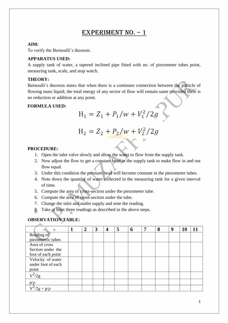
OBSERVATION TABLE:
1 2 3 4 5 6 7 8 9 10 11 Reading of piezometric tubes
Area of cross Section under the foot of each point
Velocity of water under foot of each point
V2/2g
p/ρ
V2/2g + p/ρ
2
PRECAUTIONS:
1. When fluid is flowing, there is a fluctuation in the height of piezometer tubes, note
the mean position carefully.
2. Carefully keep some level of fluid in inlet and outlet supply tank.
RESULT:
3
EXPERIMENT NO. – 2 AIM:
To determine the coefficient of discharge of Venturimeter.
APPARATUS USED:
Venturimeter, installed on different diameter pipes, arrangement of varying flow rate, U- tube
manometer, collecting tube tank, vernier calliper tube etc.
FORMULA USED:
Where
A = Cross section area of inlet
a = Cross section area of outlet
Δh = Head difference in manometer
Q = Discharge
Cd = Coefficient of discharge
g = Acceleration due to gravity
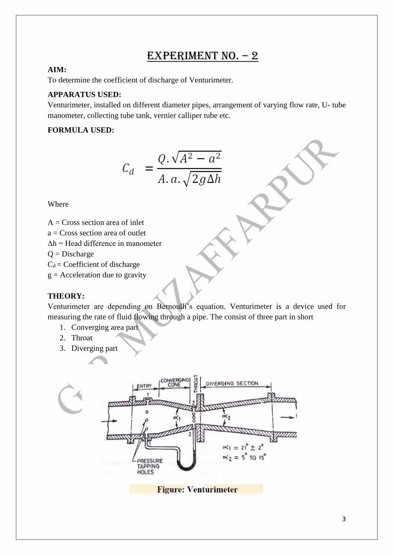
THEORY:
Venturimeter are depending on Bernoulli’s equation. Venturimeter is a device used for
measuring the rate of fluid flowing through a pipe. The consist of three part in short
1. Converging area part
2. Throat
3. Diverging part
4
PROCEDURE:
1. Set the manometer pressure to the atmospheric pressure by opening the upper
valve.
2. Now start the supply at water controlled by the stop valve.
3. One of the valves of any one of the pipe open and close all other of three.
4. Take the discharge reading for the particular flow.
5. Take the reading for the pressure head on from the u-tube manometer for
corresponding reading of discharge.
6. Now take three readings for this pipe and calculate the Cd for that instrument
using formula.
7. Now close the valve and open valve of other diameter pipe and take the three
reading for this.
8. Similarly take the reading for all other diameter pipe and calculate Cd for each.
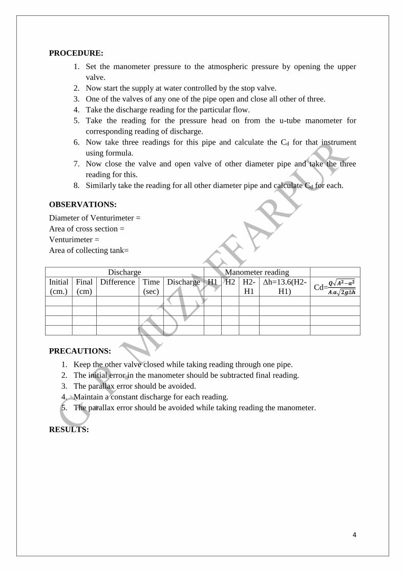
OBSERVATIONS:
Diameter of Venturimeter =
Area of cross section =
Venturimeter =
Area of collecting tank=
Discharge Manometer reading
Initial
(cm.)
Final
(cm)
Difference Time
(sec)
Discharge H1 H2 H2-
H1
Δh=13.6(H2-
H1) Cd=
𝑸√𝑨𝟐−𝒂𝟐
𝑨.𝒂√𝟐𝒈∆𝒉
PRECAUTIONS:
1. Keep the other valve closed while taking reading through one pipe.
2. The initial error in the manometer should be subtracted final reading.
3. The parallax error should be avoided.
4. Maintain a constant discharge for each reading.
5. The parallax error should be avoided while taking reading the manometer.
RESULTS:
5
EXPERIMENT NO. – 3
AIM:
To determine the coefficient of discharge, contraction & velocity of an Orifice.
APPARATUS USED:
Supply tank with overflow arrangement, Orifice plate of different diameter, hook gauge,
collecting tank, piezometric tube.
FORMULA USED:
Cd =
𝑄𝑎𝑐𝑡𝑢𝑎𝑙
𝑄𝑡ℎ𝑒𝑜𝑟𝑎𝑡𝑖𝑐𝑎𝑙
Q theoretical = Theoretical velocity × theoretical area = √2gh. a
Cd =
Q
√2gh.a
Cv = actual velocity of jet at vena contracta
theoretical velocity
Coefficient of contraction = area of jet at vena contracta
area of orifice
Cc = ac
a
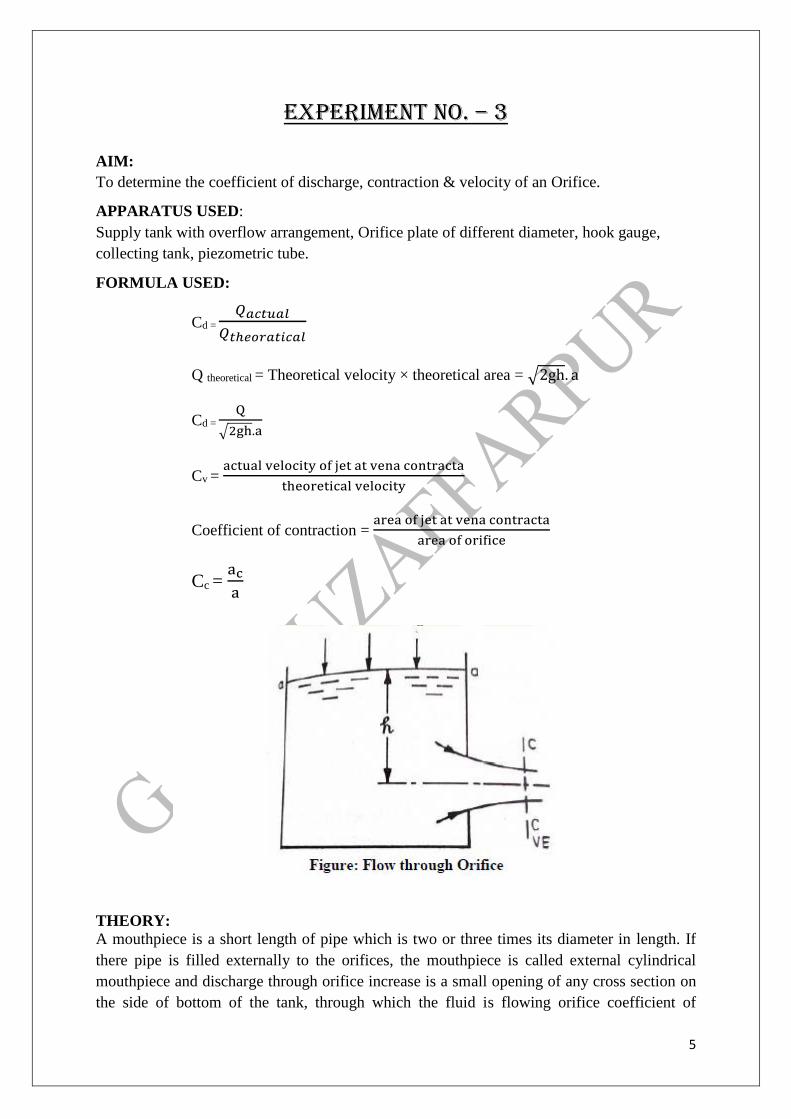
THEORY:
A mouthpiece is a short length of pipe which is two or three times its diameter in length. If
there pipe is filled externally to the orifices, the mouthpiece is called external cylindrical
mouthpiece and discharge through orifice increase is a small opening of any cross section on
the side of bottom of the tank, through which the fluid is flowing orifice coefficient of
6
velocity is defined as the ratio of two actual discharge to orifice ratio of the actual velocity of
the jet at vena-contracta to the coefficient of theoretical velocity of the jet coefficient of
contraction of defined as ratio of the actual velocity of jet at vena- contracta.
VENA- CONTRACTA:
The fluid out is in form of jet goes on contracting form orifice up to dispute of about ½ the
orifice dia. After that expand this least relation.
COEFFICIENT OF VELOCITY:
It is a ratio of actual velocity jet at vena-contracta to theoretical velocity.
Coefficient of contraction:
Coefficient of contraction = Area of jet at vena contracta
Area of orifice
COEFFICIENT OF DISCHARGE:
Cd =
𝑄𝑎𝑐𝑡𝑢𝑎𝑙
𝑄𝑡ℎ𝑒𝑜𝑟𝑎𝑡𝑖𝑐𝑎𝑙
PROCEDURE:
1. Set the mouthpiece of orifice of which the Cc, Cu, Cd are to be determined.
2. Note the initial height of water in the steady flow tank and the height of datum from the
bottom of orifice and mouthpiece. These remains constant for a particular mouthpiece or
orifice.
3. By using the stop valve, set a particular flow in tank and tank height of water in tank.
4. Take the reading of discharge on this particular flow.
5. Using hook gauge, find the volume of Xo Y for mouthpiece.
6. Take three readings using hook gauge for one particular orifice.
7. Using the formula get value of Cd, Cv, and Cc for a particular orifice and mouthpiece.
OBSERVATION: x' + y' are reading on horizontal/vertical scale
ao h=µa o x’ y’ X=x’-x oy Y=y’-yo Cv=x/2gh Average
h = Reading on piezometer
ao = Reading on piezometer at level on centre of mouthpiece
yo = Reading on vertical scale at exit of orifice
xo = Reading on horizontal scale at exit of orifice
7
Sr. No. X ZP FR volume time Q=V Cd=Q/2gh Average
PRECAUTIONS:
1. Take the reading of discharge accurately.
2. Take value of h without any parallax error.
3. Set the orifice and mouthpiece.
4. Height of water in the steady flow.
5. Take reading from hook gauge carefully.
RESULT:
8
EXPERIMENT NO. – 4 AIM:
To determine the friction factor for the pipes. (Major Losses).
APPARATUS USED:
A flow circuit of G. I. pipes of different diameter viz. 15 mm, 25mm, 32 mm dia, U-tube
differential manometer, collecting tank.
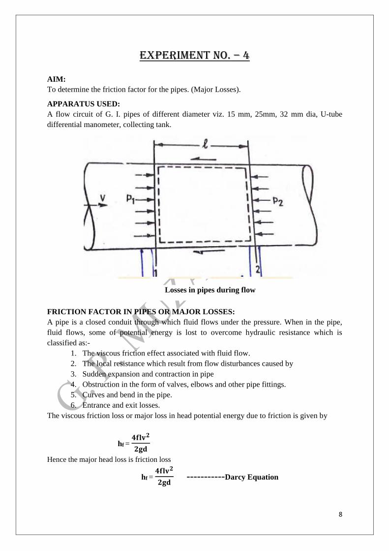
FRICTION FACTOR IN PIPES OR MAJOR LOSSES:
A pipe is a closed conduit through which fluid flows under the pressure. When in the pipe,
fluid flows, some of potential energy is lost to overcome hydraulic resistance which is
classified as:-
1. The viscous friction effect associated with fluid flow.
2. The local resistance which result from flow disturbances caused by
3. Sudden expansion and contraction in pipe
4. Obstruction in the form of valves, elbows and other pipe fittings.
5. Curves and bend in the pipe.
6. Entrance and exit losses.
The viscous friction loss or major loss in head potential energy due to friction is given by
hf = 𝟒𝐟𝐥𝐯𝟐
𝟐𝐠𝐝
Hence the major head loss is friction loss
hf = 𝟒𝐟𝐥𝐯𝟐
𝟐𝐠𝐝 -----------Darcy Equation
Losses in pipes during flow
9
Where,
hf =Major head loss
l = Length of pipe
4f = Friction factor
v = Inlet velocity
g = Acceleration due to gravity
d = Diameter of pipe
PROCEDURE:
1. Note down the relevant dimensions as diameter and length of pipe between the
pressure tapping, area of collecting tank etc.
2. Pressure tapping of a pipe is kept open while for other pipe is closed.
3. The flow rate was adjusted to its maximum value. By maintaining suitable amount of
steady flow in the pipe.
4. The discharge flowing in the circuit is recorded together with the water level in the
left and right limbs of manometer tube.
5. The flow rate is reduced in stages by means of flow control valve and the discharge &
reading of manometer are recorded.
6. This procedure is repeated by closing the pressure tapping of this pipe, together with
other pipes and for opening of another pipe.
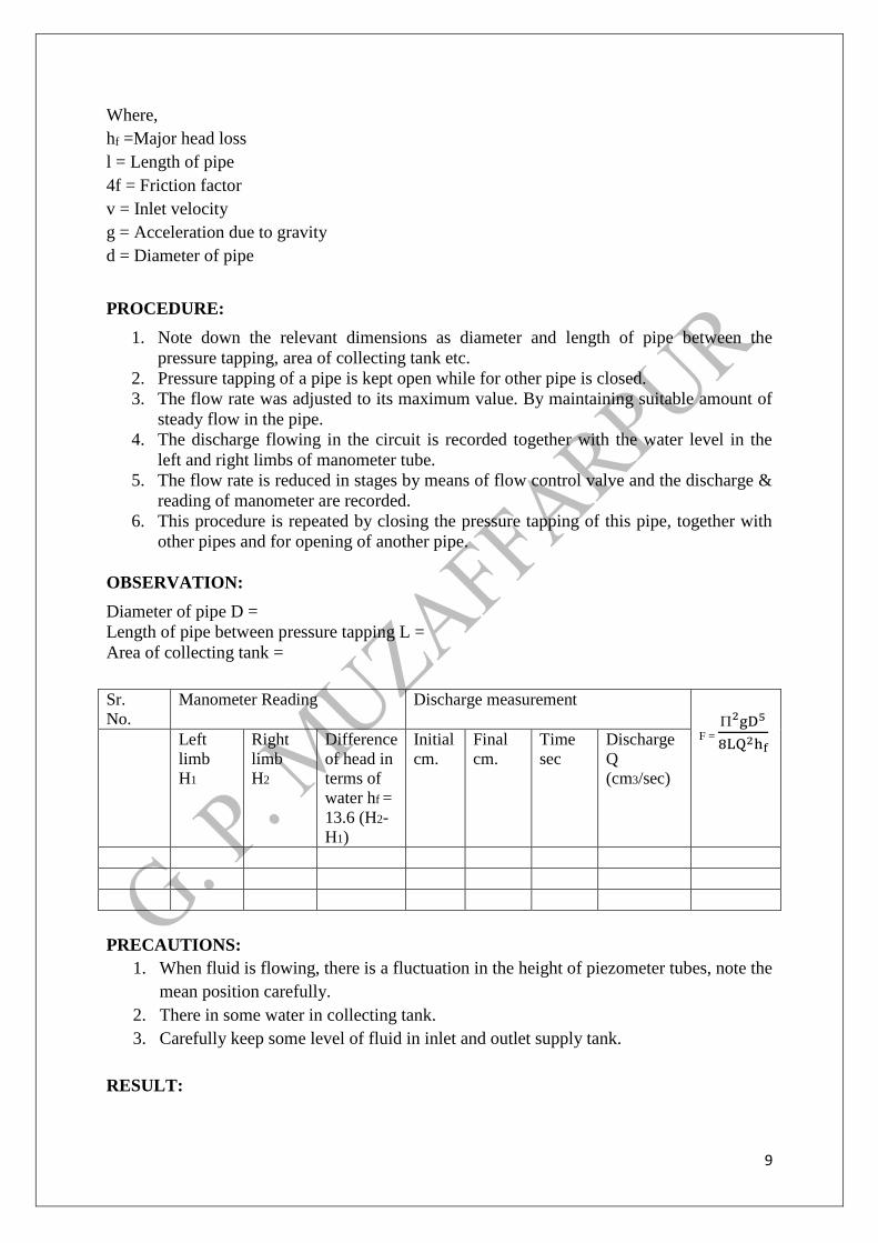
OBSERVATION:
Diameter of pipe D =
Length of pipe between pressure tapping L =
Area of collecting tank =
Sr.
No.
Manometer Reading Discharge measurement
F =
2gD5
8LQ2hf
Left
limb
H1
Right
limb
H2
Difference
of head in
terms of
water hf =
13.6 (H2-
H1)
Initial
cm.
Final
cm.
Time
sec
Discharge
Q
(cm3/sec)
PRECAUTIONS:
1. When fluid is flowing, there is a fluctuation in the height of piezometer tubes, note the
mean position carefully.
2. There in some water in collecting tank.
3. Carefully keep some level of fluid in inlet and outlet supply tank.
RESULT:
10
EXPERIMENT NO. – 5 AIM:
To conduct the performance test and to plot the operating characteristics of Pelton wheel
turbine.
APPARATUS:
Pelton wheel test rig, Tachometer.
THEORY:
Pelton turbine is a impulse turbine. Which uses water available at high heads (pressure) for
generation of electricity. All the available potential energy of the water is converted into
kinetic energy by a nozzle arrangement. The water leaves the nozzle as a jet and strikes the
buckets of the Pelton wheel runner. These buckets are in the shape of double cups, joined at
the middle portion in a knife edge. The jet strikes the knife edge of the bucket with the least
resistance and shock and glides along the path of the cup, deflecting through an angle of 160°
to 170°.This deflection of the water causes a change in momentum of the water jet and hence
an impulse force is supplied to the buckets. As a result, the runner attached to the bucket
moves, rotating the shaft. The specific speed of Pelton wheel varies from 10 to 100.
In the test rig the Pelton wheel is supplied with water under the high pressure by a centrifugal
pump. The water flows through the venturimeter to the Pelton wheel. A gate valve is used to
control the flow rate to the turbine. The venturimeter with pressure gauges is connected to
determine the flow rate in the pipe. The nozzle opening can be decreased or increased by
opening the spear wheel at entrance side of the turbine.
The turbine is loaded by applying the dead weights on the brake drum. Placing the weights on
the weight hanger. The inlet head is read from the pressure gauge. The speed of the turbine is
measured with the help of tachometer.
EXPERIMENTAL PROCEDURE:
1. Prime the pump with water and start the pump.
2. Gradually open the delivery valve of the pump.
3. Adjust the nozzle at the half of the opening by operating the needle valve by using the
spear wheel.
4. The head should be made constant by operating the delivery valve and the head shows
be maintained at constant value.
5. Measure the turbine rpm with the tachometer.
6. Note the pressure gauge reading at the turbine inlet.
7. Observe the readings of h 1 and h 2 corresponding the fluid level in the two
manometer links which are connected to venturimeter.
8. Adjust the load on the break drum and note down the speed of the turbine, using the
tachometer and spring balance reading.
9. Add additional weights and repeat the experiment for other loads.
10. For constant speed tests, the main valve has to be adjusted to reduce or increase the
inlet head to the turbine for varying loads spring balance reading.
11
11. Add additional weights and repeat the experiment for other loads.
12. For constant speed tests, the main valve has to be adjusted to reduce or increase the
inlet head to the turbine for varying loads.
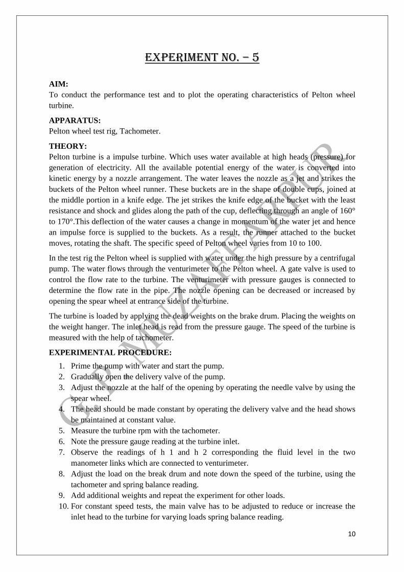
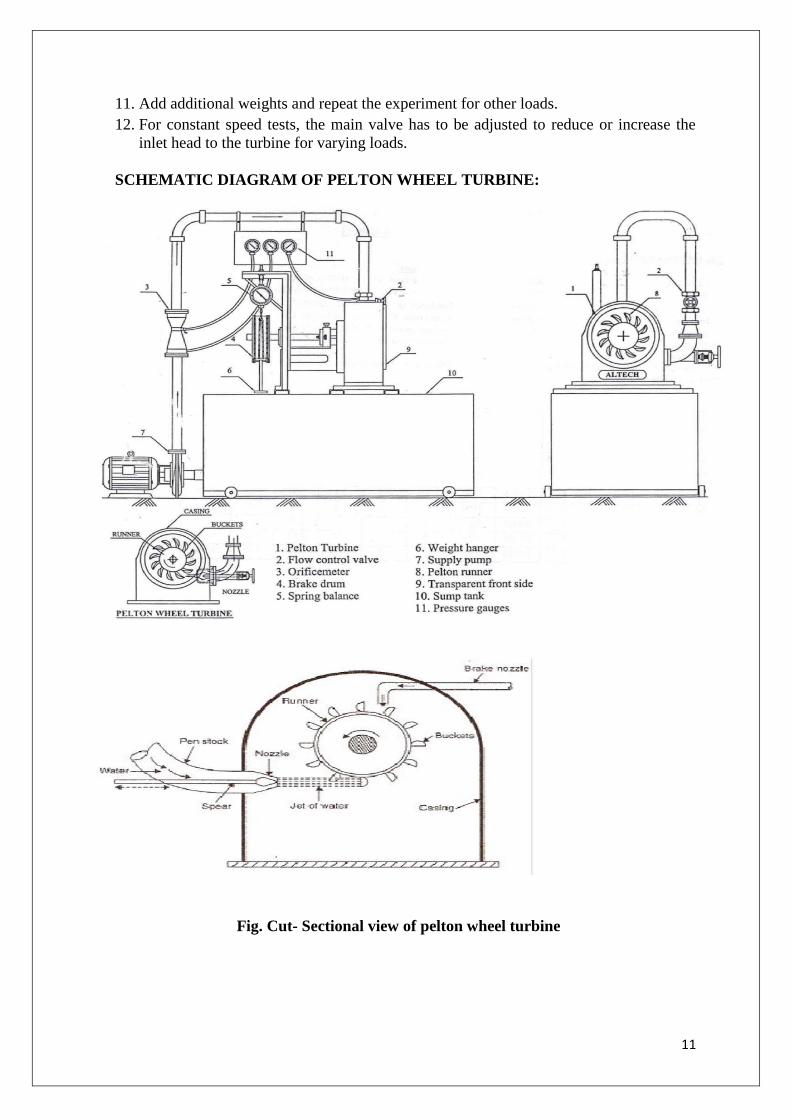
SCHEMATIC DIAGRAM OF PELTON WHEEL TURBINE:
Fig. Cut- Sectional view of pelton wheel turbine
12
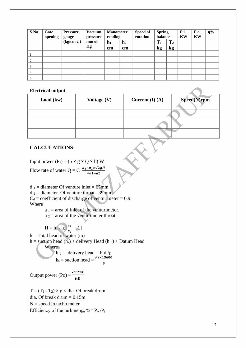
S.No Gate
opening
Pressure
gauge
(kg/cm 2 )
Vacuum
pressure
mm of
Hg
Manometer
reading
Speed of
rotation
Spring
balance
P i
KW
P o
KW
η%
h1
cm
h2
cm
T1
kg
T2
kg
1
2
3
4
5
Electrical output
Load (kw) Voltage (V) Current (I) (A) Speed(N)rpm
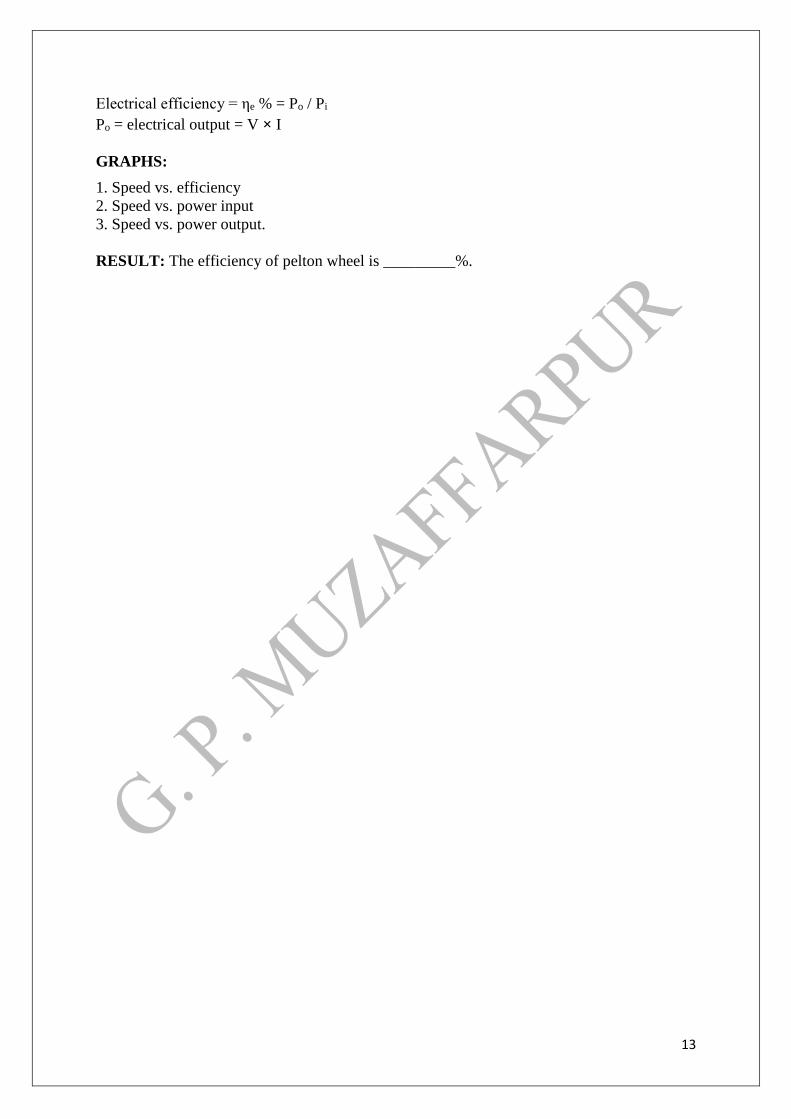
CALCULATIONS:
Input power (Pi) = (ρ × g × Q × h) W
Flow rate of water Q = Cd 𝒂𝟏×𝒂𝟐×√𝟐𝒈𝑯
√𝒂𝟏−𝒂𝟐
d 1 = diameter Of venture inlet = 65mm
d 2 = diameter. Of venture throat= 39mm
Cd = coefficient of discharge of venturimeter = 0.9
Where
a 1 = area of inlet of the venturimeter.
a 2 = area of the venturimeter throat.
H = h1 - h2 [𝑠1
𝑠2− 1]
h = Total head of water (m)
h = suction head (hs) + delivery Head (h d) + Datum Head
Where
h d = delivery head = P d /ρ
hs = suction head = 𝑷𝒔×𝟏𝟑𝟔𝟎𝟎
𝛒
Output power (Po) = 𝟐𝛑×𝑵×𝑻
𝟔𝟎
T = (T1 - T2) × g × dia. Of break drum
dia. Of break drum = 0.15m
N = speed in tacho meter
Efficiency of the turbine ηm %= Po /Pi
13
Electrical efficiency = ηe % = Po / Pi
Po = electrical output = V × I
GRAPHS:
1. Speed vs. efficiency
2. Speed vs. power input
3. Speed vs. power output.
RESULT: The efficiency of pelton wheel is _________%.
14
EXPERIMENT NO. – 6
AIM:
To conduct performance test on a Single stage Centrifugal pump test rig.
INTRODUCTION:
A pump may be defined as mechanical device when interposed in a pipe line, converts the
mechanical energy supplied to it from an external source into hydraulic energy, thus resulting
in the flow of liquid from lower potential to higher potential.
The pumps are of major concern to most engineers and technicians. The types of pumps vary
in principle and design. The selection of the pump for any particular application is to be done
by understanding their characteristics. The most commonly used pumps for domestic,
agricultural and industrial are Centrifugal, axial flow, reciprocating, air jet, and diaphram and
turbine pumps. Most of these pumps fall into the main class namely Rotodynamic,
Reciprocating (positive displacement) and Fluid operated pumps.
THEORY:
The principle of operation of a single stage centrifugal pump is covered under Rotodynamic
pump category. In this pump, the liquid is made to rotate in a closed volute chamber. Thus
creating the centrifugal action, which gradually builds the pressure gradient towards outlet
resulting in a continuous flow.
These pumps are of simple construction can be directly coupled to electric motor and more
suitable for handling clear, semi viscous, as well as turbid liquids. The hydraulic head per
stage at low flow rates is limited and hence not suitable for high heads, in case of single stage
centrifugal pumps. But as the pump in this case in a multi stage construction the pressure
gradually builds up in successive stages almost equally in each stage. Thus achieving
considerably higher heads. The multi stage centrifugal pump test rig allows the students to
understand and study the various characteristics and pressure build up pattern in individual
stages.
DESCRIPTION:
The single stage Centrifugal pump test rig mainly consists of:
a) Single stage Centrifugal pump
b) AC Drive motor of suitable capacity coupled to pump by stepped pulley arrangement.
c) SS sump tank and measuring tank with a piezometer
d) G. I. Pipe connections with necessary control valve etc… mounted on a neatly painted
M.S. structure. The panel board is equipped with an energy meter for measurement of power
input to the motor, a digital RPM indicator to indicate the speed of the pump/motor, a
Vacuum gauge to measure suction head, & pressure gauge for measurement of delivery head,
a starter of suitable capacity, indicating lamps and fuse etc.
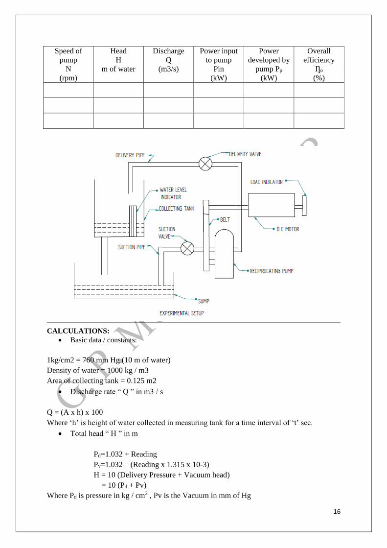
CALCULATIONS:
Basic data / constants:
1 kg /cm2 = 760 mm Hg (10 m of water)
15
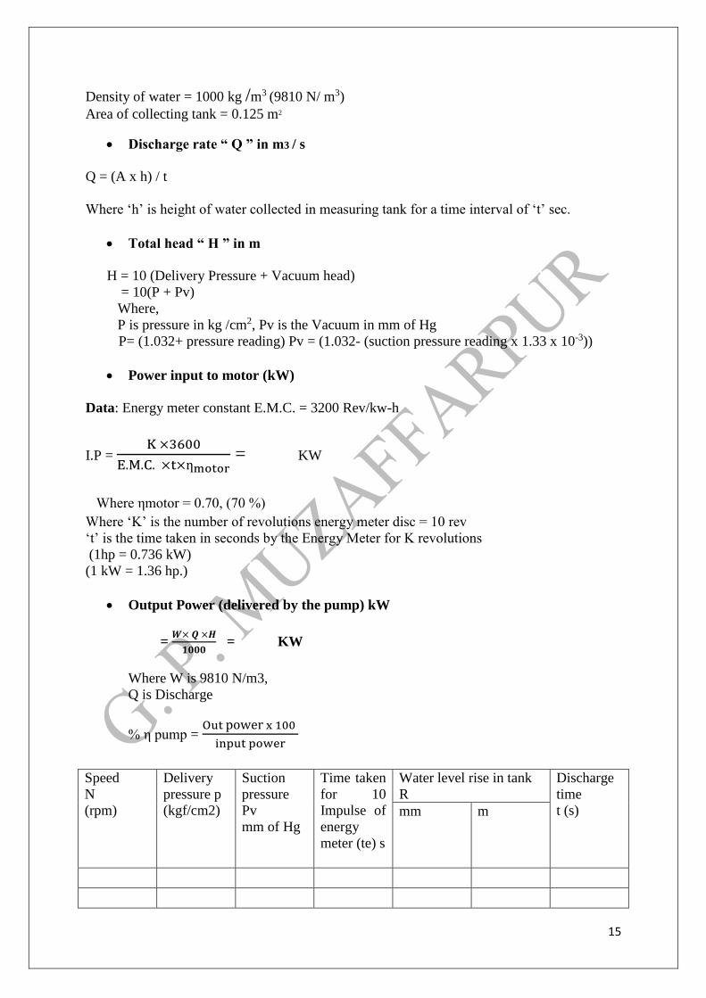
Density of water = 1000 kg /m3 (9810 N/ m3)
Area of collecting tank = 0.125 m2
Discharge rate “ Q ” in m3 / s
Q = (A x h) / t
Where ‘h’ is height of water collected in measuring tank for a time interval of ‘t’ sec.
Total head “ H ” in m
H = 10 (Delivery Pressure + Vacuum head)
= 10(P + Pv)
Where,
P is pressure in kg /cm2, Pv is the Vacuum in mm of Hg
P= (1.032+ pressure reading) Pv = (1.032- (suction pressure reading x 1.33 x 10⁻³))
Power input to motor (kW)
Data: Energy meter constant E.M.C. = 3200 Rev/kw-h
I.P = K ×3600
E.M.C. ×t×ƞmotor = KW
Where ηmotor = 0.70, (70 %)
Where ‘K’ is the number of revolutions energy meter disc = 10 rev
‘t’ is the time taken in seconds by the Energy Meter for K revolutions
(1hp = 0.736 kW)
(1 kW = 1.36 hp.)
Output Power (delivered by the pump) kW
= 𝑾× 𝑸 ×𝑯
𝟏𝟎𝟎𝟎 = KW
Where W is 9810 N/m3,
Q is Discharge
% η pump = Out power x 100
input power
Speed
N
(rpm)
Delivery
pressure p
(kgf/cm2)
Suction
pressure
Pv
mm of Hg
Time taken
for 10
Impulse of
energy
meter (te) s
Water level rise in tank
R
Discharge
time
t (s) mm m
16
Speed of
pump
N
(rpm)
Head
H
m of water
Discharge
Q
(m3/s)
Power input
to pump
Pin
(kW)
Power
developed by
pump Pp
(kW)
Overall
efficiency
Ƞo
(%)
CALCULATIONS:
Basic data / constants:
1kg/cm2 = 760 mm Hg (10 m of water)
Density of water = 1000 kg / m3
Area of collecting tank = 0.125 m2
Discharge rate “ Q ” in m3 / s
Q = (A x h) x 100
Where ‘h’ is height of water collected in measuring tank for a time interval of ‘t’ sec.
Total head “ H ” in m
Pd=1.032 + Reading
Pv=1.032 – (Reading x 1.315 x 10⁻³)
H = 10 (Delivery Pressure + Vacuum head)
= 10 (Pd + Pv)
Where Pd is pressure in kg / cm2 , Pv is the Vacuum in mm of Hg
17
EXPERIMENT NO-7
AIM:
To determine the overall efficiency of a Reciprocating Pump.
INTRODUCTION:
Reciprocating pump is a positive displacement plunger pump. It is often used where
relatively small quantity of water is to be handled and delivery pressure is quite large.
Reciprocating pumps are widely used as Automobile Service Stations, Chemical Industries,
or as metering and dosing pumps.
The apparatus consists of a two cylinder, double acting reciprocating pump mounted over the
sump tank. The pump is driven by DC motor. An energy meter measures electrical input to
motor. Measuring tank is provided to measure discharge of the pump. The pressure and
vacuum gauges provided to measure the delivery pressure and suction vacuum respectively.
SPECIFICATIONS:-
1. Reciprocating pump - stroke length 16 mm, piston dia 22 mm. 2 piston, with air
vessel on discharge side, suction 15 mm discharge 15 mm.
2. DC motor, 1 HP 1440 RPM.
3. Measuring tank – 300 X 400 X 300 mm height provided with gauge tube and
funnel for diverting the flow into measuring tank or sump tank.
4. Sump tank – 600 X 500 X 300 mm height.
i. Pressure gauge 0 - 2 1 Kg/cm2 for discharge pressure,
ii. Vacuum gauge 0 -760 mm Hg for suction vacuum,
iii. Energy meter for motor input measurement.
PROCEDURE:
1. Fill up sufficient water in sump tank.
2. Open the gate valve in the discharge pipe of the pump fully.
3. Check nut bolts & the driving belt for proper tightening.
4. Connect the electric supply and switch on the supply.
5. Slightly close the discharge valve. Note down pump speed, delivery
6. Pressure, suction vacuum, time for 10imps of energy meter & for flow
measurement close the measuring tanks drain valve, take time for 10 lits.
7. Repeat the procedure for different gate valve closing. Take care that discharge
pressure does not rise above 8 Kg/cm2.
8. Change the speed and take readings for different gate valve openings.
OBSERVATIONS:-
Piston Dia (m) “D” = 0.022 m
Suction Stroke (m) “l” = 0.016 m
Volume per Stroke(m3) “Vs” = 1.2164 * 10-5
18
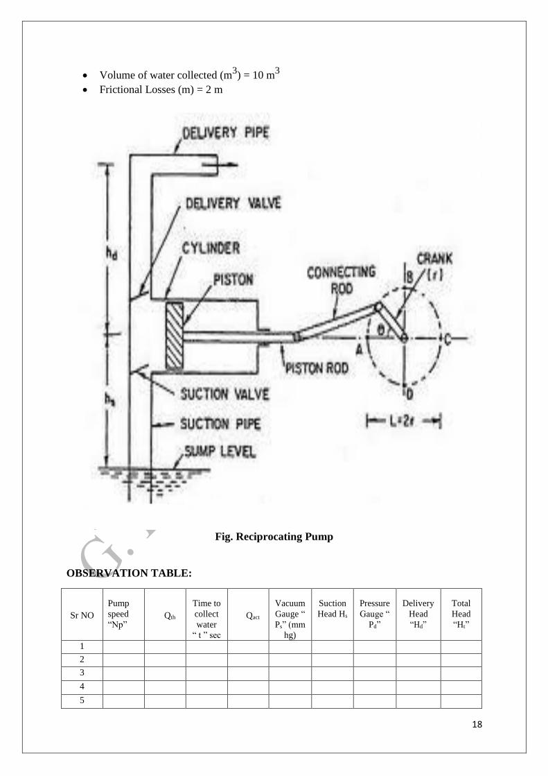
Volume of water collected (m3) = 10 m
3
Frictional Losses (m) = 2 m
Fig. Reciprocating Pump
OBSERVATION TABLE:
Sr NO
Pump
speed
“Np”
Qth
Time to
collect
water
“ t ” sec
Qact
Vacuum
Gauge “
Ps” (mm
hg)
Suction
Head Hs
Pressure
Gauge “
Pd”
Delivery
Head
“Hd”
Total
Head
“Ht”
1
2
3
4
5
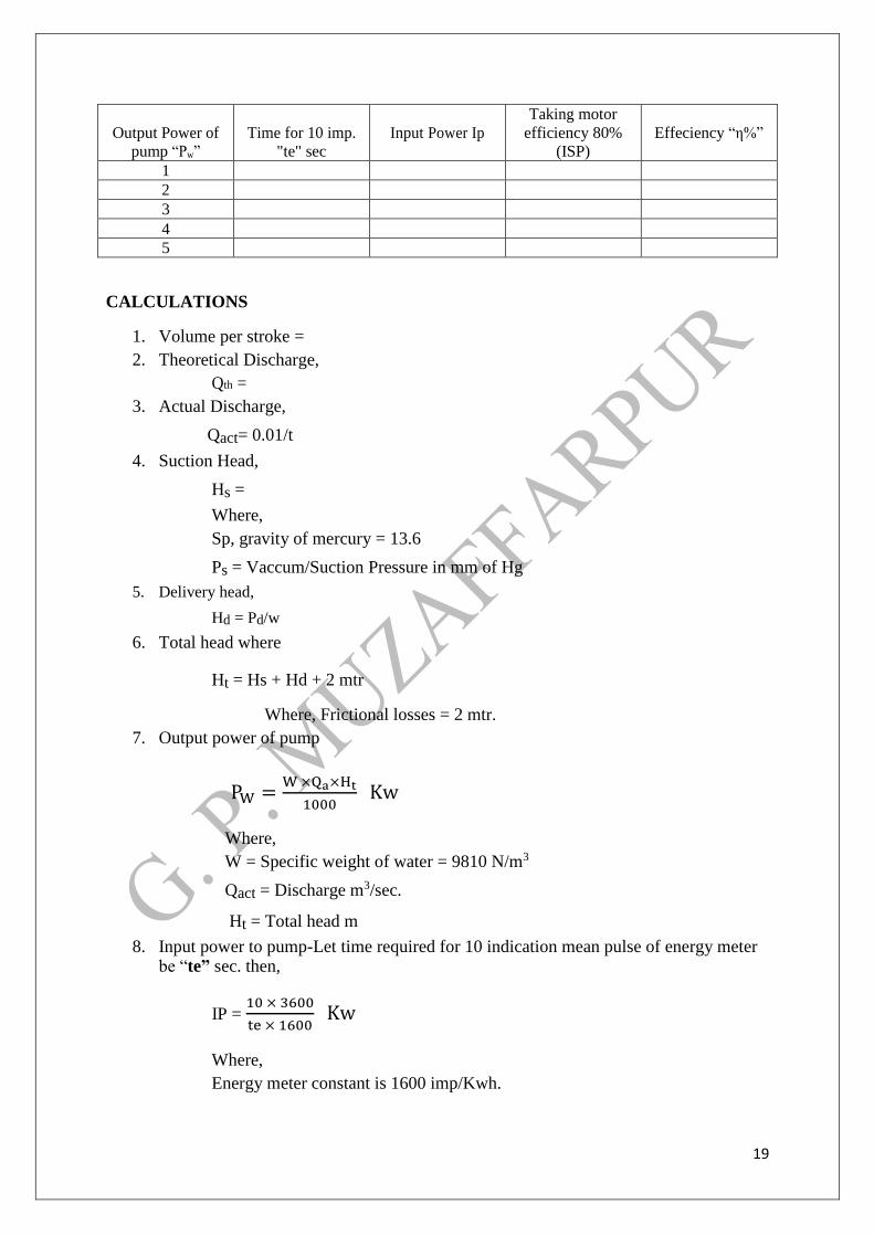
19
Output Power of
pump “Pw”
Time for 10 imp.
"te" sec
Input Power Ip
Taking motor
efficiency 80%
(ISP)
Effeciency “η%”
1
2
3
4
5
CALCULATIONS
1. Volume per stroke =
2. Theoretical Discharge,
Qth =
3. Actual Discharge,
Qact= 0.01/t
4. Suction Head,
Hs =
Where,
Sp, gravity of mercury = 13.6
Ps = Vaccum/Suction Pressure in mm of Hg
5. Delivery head,
Hd = Pd/w
6. Total head where
Ht = Hs + Hd + 2 mtr
Where, Frictional losses = 2 mtr.
7. Output power of pump
PW =W ×Qa×Ht
1000 Kw
Where,
W = Specific weight of water = 9810 N/m3
Qact = Discharge m3/sec.
Ht = Total head m
8. Input power to pump-Let time required for 10 indication mean pulse of energy meter be “te” sec. then,
IP = 10 × 3600
te × 1600 Kw
Where,
Energy meter constant is 1600 imp/Kwh.
20
9. Taking motor efficiency 80 %, we have input shaft
Power S.P. = I.P. x 0.80
10. Overall efficiency of pump =
Result -:
From Observations:
1. Maximum Efficiency = ή = ……………………..%
2. I.H.P = ………
3. Total Head = …….
4. B.H.P. (output) = ………….