GOOD MANUFACTURING PRACTICES FOR … This document represents Part 2 of the HVAC systems guidelines....
21
Working document QAS/18.759 February 2018 Draft document for comment 1 2 GOOD MANUFACTURING PRACTICES FOR HEATING, VENTILATION 3 AND AIR-CONDITIONING SYSTEMS FOR NON-STERILE 4 PHARMACEUTICAL DOSAGE FORMS: PART 2 5 6 INTERPRETATION OF PART 1 – GMP FOR HVAC SYSTEMS 7 8 (February 2018) 9 DRAFT FOR COMMENT 10 11 12 13 14 15 © World Health Organization 2018 16 All rights reserved. 17 This draft is intended for a restricted audience only, i.e. the individuals and organizations having received this draft. The 18 draft may not be reviewed, abstracted, quoted, reproduced, transmitted, distributed, translated or adapted, in part or in whole, 19 in any form or by any means outside these individuals and organizations (including the organizations' concerned staff and 20 member organizations) without the permission of the World Health Organization. The draft should not be displayed on any 21 website. 22 Please send any request for permission to: 23 Dr Sabine Kopp, Group Lead, Medicines Quality Assurance, Technologies Standards and Norms, Department of Essential 24 Medicines and Health Products, World Health Organization, CH-1211 Geneva 27, Switzerland. Fax: (41-22) 791 4730; 25 email: [email protected] 26 27 The designations employed and the presentation of the material in this draft do not imply the expression of any opinion 28 whatsoever on the part of the World Health Organization concerning the legal status of any country, territory, city or area or 29 of its authorities, or concerning the delimitation of its frontiers or boundaries. Dotted lines on maps represent approximate 30 border lines for which there may not yet be full agreement. 31 The mention of specific companies or of certain manufacturers’ products does not imply that they are endorsed or 32 recommended by the World Health Organization in preference to others of a similar nature that are not mentioned. Errors 33 and omissions excepted, the names of proprietary products are distinguished by initial capital letters. 34 All reasonable precautions have been taken by the World Health Organization to verify the information contained in this 35 draft. However, the printed material is being distributed without warranty of any kind, either expressed or implied. The 36 responsibility for the interpretation and use of the material lies with the reader. In no event shall the World Health 37 Organization be liable for damages arising from its use. 38 This draft does not necessarily represent the decisions or the stated policy of the World Health Organization. 39 40 Should you have any comments on the attached text, please send these to Dr S. Kopp, Group Lead, Medicines Quality Assurance, Technologies Standards and Norms ([email protected]) with a copy to Mrs Xenia Finnerty ([email protected]) by 26 April 2018. Medicines Quality Assurance working documents will be sent out electronically only and will also be placed on the Medicines website for comment under “Current projects”. If you do not already receive our draft working documents please let us have your email address (to [email protected]) and we will add it to our electronic mailing list.
Transcript of GOOD MANUFACTURING PRACTICES FOR … This document represents Part 2 of the HVAC systems guidelines....

Working document QAS/18.759
February 2018
Draft document for comment
1
2
GOOD MANUFACTURING PRACTICES FOR HEATING, VENTILATION 3
AND AIR-CONDITIONING SYSTEMS FOR NON-STERILE 4
PHARMACEUTICAL DOSAGE FORMS: PART 2 5
6
INTERPRETATION OF PART 1 – GMP FOR HVAC SYSTEMS 7
8
(February 2018) 9
DRAFT FOR COMMENT 10
11
12
13
14
15
© World Health Organization 2018 16
All rights reserved. 17
This draft is intended for a restricted audience only, i.e. the individuals and organizations having received this draft. The 18 draft may not be reviewed, abstracted, quoted, reproduced, transmitted, distributed, translated or adapted, in part or in whole, 19 in any form or by any means outside these individuals and organizations (including the organizations' concerned staff and 20 member organizations) without the permission of the World Health Organization. The draft should not be displayed on any 21 website. 22
Please send any request for permission to: 23
Dr Sabine Kopp, Group Lead, Medicines Quality Assurance, Technologies Standards and Norms, Department of Essential 24 Medicines and Health Products, World Health Organization, CH-1211 Geneva 27, Switzerland. Fax: (41-22) 791 4730; 25 email: [email protected] 26 27 The designations employed and the presentation of the material in this draft do not imply the expression of any opinion 28 whatsoever on the part of the World Health Organization concerning the legal status of any country, territory, city or area or 29 of its authorities, or concerning the delimitation of its frontiers or boundaries. Dotted lines on maps represent approximate 30 border lines for which there may not yet be full agreement. 31
The mention of specific companies or of certain manufacturers’ products does not imply that they are endorsed or 32 recommended by the World Health Organization in preference to others of a similar nature that are not mentioned. Errors 33 and omissions excepted, the names of proprietary products are distinguished by initial capital letters. 34
All reasonable precautions have been taken by the World Health Organization to verify the information contained in this 35 draft. However, the printed material is being distributed without warranty of any kind, either expressed or implied. The 36 responsibility for the interpretation and use of the material lies with the reader. In no event shall the World Health 37 Organization be liable for damages arising from its use. 38
This draft does not necessarily represent the decisions or the stated policy of the World Health Organization. 39 40
Should you have any comments on the attached text, please send these to Dr S. Kopp,
Group Lead, Medicines Quality Assurance, Technologies Standards and Norms
([email protected]) with a copy to Mrs Xenia Finnerty ([email protected])
by 26 April 2018.
Medicines Quality Assurance working documents will be sent out electronically only and
will also be placed on the Medicines website for comment under “Current projects”. If you
do not already receive our draft working documents please let us have your email address
(to [email protected]) and we will add it to our electronic mailing list.
Working document QAS/18.759 page 2
41
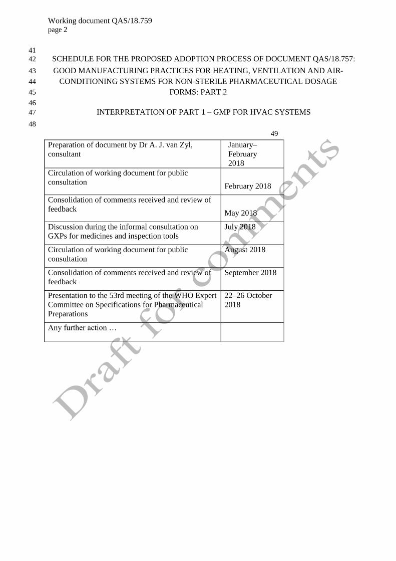
SCHEDULE FOR THE PROPOSED ADOPTION PROCESS OF DOCUMENT QAS/18.757: 42
GOOD MANUFACTURING PRACTICES FOR HEATING, VENTILATION AND AIR-43
CONDITIONING SYSTEMS FOR NON-STERILE PHARMACEUTICAL DOSAGE 44
FORMS: PART 2 45
46
INTERPRETATION OF PART 1 – GMP FOR HVAC SYSTEMS 47
48
49
Preparation of document by Dr A. J. van Zyl,
consultant
January–
February
2018
Circulation of working document for public
consultation
February 2018
Consolidation of comments received and review of
feedback
May 2018
Discussion during the informal consultation on
GXPs for medicines and inspection tools
July 2018
Circulation of working document for public
consultation
August 2018
Consolidation of comments received and review of
feedback
September 2018
Presentation to the 53rd meeting of the WHO Expert
Committee on Specifications for Pharmaceutical
Preparations
22–26 October
2018
Any further action …
Working document QAS/18.759 page 3
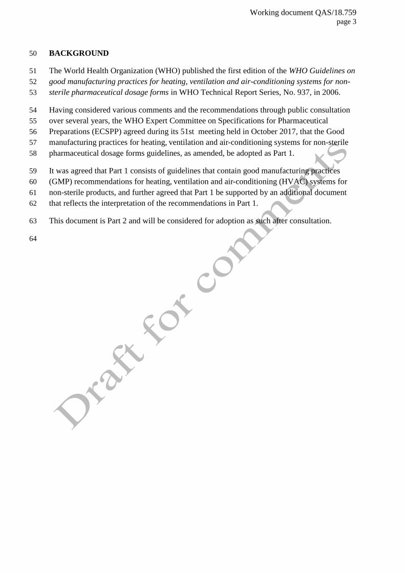
BACKGROUND 50
The World Health Organization (WHO) published the first edition of the WHO Guidelines on 51
good manufacturing practices for heating, ventilation and air-conditioning systems for non-52
sterile pharmaceutical dosage forms in WHO Technical Report Series, No. 937, in 2006. 53
Having considered various comments and the recommendations through public consultation 54
over several years, the WHO Expert Committee on Specifications for Pharmaceutical 55
Preparations (ECSPP) agreed during its 51st meeting held in October 2017, that the Good 56
manufacturing practices for heating, ventilation and air-conditioning systems for non-sterile 57
pharmaceutical dosage forms guidelines, as amended, be adopted as Part 1. 58
It was agreed that Part 1 consists of guidelines that contain good manufacturing practices 59
(GMP) recommendations for heating, ventilation and air-conditioning (HVAC) systems for 60
non-sterile products, and further agreed that Part 1 be supported by an additional document 61
that reflects the interpretation of the recommendations in Part 1. 62
This document is Part 2 and will be considered for adoption as such after consultation. 63
64
Working document QAS/18.759 page 4
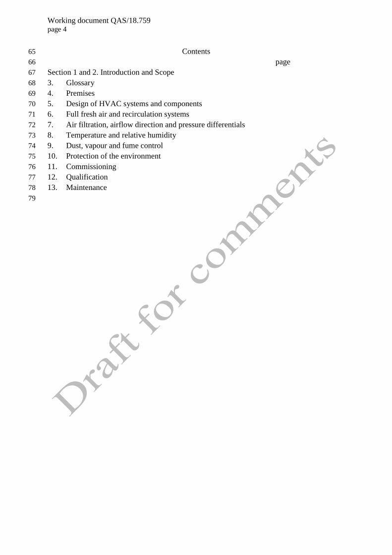
Contents 65
page 66
Section 1 and 2. Introduction and Scope 67
3. Glossary 68
4. Premises 69
5. Design of HVAC systems and components 70
6. Full fresh air and recirculation systems 71
7. Air filtration, airflow direction and pressure differentials 72
8. Temperature and relative humidity 73
9. Dust, vapour and fume control 74
10. Protection of the environment 75
11. Commissioning 76
12. Qualification 77
13. Maintenance 78
79

Working document QAS/18.759 page 5
Section 1 and 2 : Introduction and Scope 80
81
This document represents Part 2 of the HVAC systems guidelines. It contains non-binding 82
examples, drawings, technical representations and interpretation in support of Part 1 of the 83
HVAC systems guidelines. 84
85
It is intended to be a basic and explanatory guide for use by pharmaceutical manufacturers 86
and GMP inspectors. It is not intended to be prescriptive in specifying requirements and design 87
parameters but it attempts to facilitate a harmonized understanding of expectations for HVAC 88
systems for manufacturers of non-sterile products. 89
90
Part 1 and Part 2 focus on good practices for HVAC systems for non-sterile products. Where 91
applicable, some of the principles referred to may be considered in the HVAC design and 92
approach for other dosage forms. These two documents are, however, not intended to be used 93
as enforceable criteria for the design or review of HVAC systems for, e.g. APIs or sterile 94
products. 95
96
Other relevant national and international standards, as applicable, should be considered when 97
Part 1 and Part 2 are used. These include, but are not limited to, the current publications such 98
as ISO 14644 and ASHRAE standards. 99
100
In general, HVAC systems can play an important role in facilitating a suitable environment 101
for the manufacture of quality pharmaceutical products. Therefore careful consideration should 102
be given to the design of the HVAC system. When designing an HVAC system, careful 103
consideration should also be given to the building design and layout of areas as these may 104
influence the decision and design relating to, for example, the number of air handling units 105
(AHUs), components in AHUs, room pressure, pressure differentials, pressure cascades, 106
levels of filtration, humidification, dehumidification, heating and cooling of air. These may in 107
turn have an impact on the quality of materials and products as well as the functioning of 108
equipment and instruments. 109
110
The conditions of areas should be defined and should be appropriate for the storage, 111
manufacturing and use, as appropriate, for equipment, instruments, materials and products. It 112
should further ensure that comfortable conditions are maintained for operators. 113
114
Risk assessment 115
116
In line with the current approach in GMP, risk identification should be done for utilities such 117
as HVAC systems. A science-based, comprehensive exercise of risk assessment should be 118
used to determine risks related to possible failure of the HVAC system and AHUs (including 119
their components and subcomponents). An appropriate risk assessment tool such as failure 120
modes and effects analysis (FMEA) or fault tree analysis (FTA) should be selected. Controls 121
should be identified to eliminate the risks, or minimize the risk to an acceptable level. For 122
example, the effect of the failure of one or more AHUs in the HVAC system; the failure of 123

Working document QAS/18.759 page 6
dust extraction systems; the failure of AHU components such as filters, heating coils, cooling 124
coils and fans should be assessed and appropriate controls should be identified and 125
implemented. 126
127
For more information on risk assessment, refer the current WHO guidelines on Quality risk 128
management. 129
130
Design parameters 131
132
Manufacturers should define the design parameters of the HVAC system to ensure 133
appropriate operation and functioning of the system that is needed for all the areas. Special 134
consideration should be given to the required conditions for storage and handling of materials 135
and products, equipment and instrument functioning, personnel requirements and 136
contamination control. 137
138
Section 3. Glossary 139
140
For definitions and abbreviations, see Part 1. 141
142
143
Working document QAS/18.759 page 7
Section 4. Premises 144
145
Premises design 146
147
Both the architectural design of the building and that of the HVAC system should be 148
carefully considered when attempting to achieve the general objectives of preventing 149
contamination, cross-contamination and ensuring an appropriate environment for the 150
production and control of pharmaceutical products. The layout of the premises should 151
facilitate unidirectional flow of material and personnel; building finishes should not result in 152
contamination (e.g. through shedding of particles) and should ensure that the required 153
environmental conditions, cleanliness and containment are achieved and maintained. 154
155
Air infiltration of unfiltered air into production areas should be prevented. Manufacturing 156
facilities should normally be maintained at a positive pressure relative to the outside, to limit 157
the ingress of contaminants. Where facilities are to be maintained at negative pressures 158
relative to the ambient pressure, special precautions should be taken. 159
160
Where necessary, air locks, change rooms and pass-through hatches may be considered and 161
provided with effective ventilation and filtered air. Special attention should be given to door 162
design as gaps between doors and floors, doors opening into low pressure areas and sliding 163
doors can result in changes in pressure differential between areas. An interlocking system and 164
a visual and/or audible warning system may be used to prevent the opening of more than one 165
door at a time where required. 166
167
In addition to the design of the premises, general controls should be in place to ensure 168
protection of materials, products and personnel. The HVAC system can play a role in 169
achieving this objective. Where identified, areas should be maintained within defined limits 170
for temperature, relative humidity, viable and non-viable particles. In such cases, the areas 171
are considered to be “clean areas” (also referred to as “zones, rooms”, etc.). To ensure that 172
the clean area is maintained at the defined limits, areas are normally classified. When 173
classifying the area, the manufacturer should state whether the classification is for the “as 174
built”, “at rest” or “in operation” condition. For details including definitions, see ISO 14644. 175
The following describes approaches (and illustrations by means of diagrams) of different 176
room arrangements and room pressures. 177
Weighing/dispensing and sampling areas 178
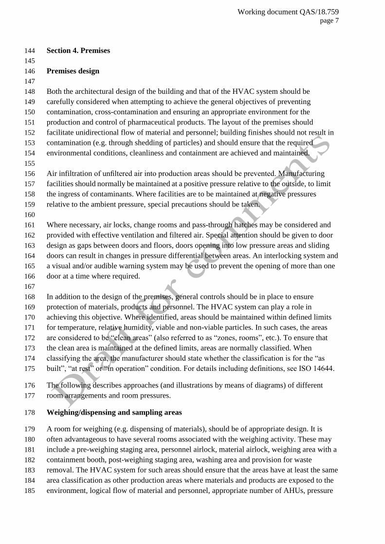
A room for weighing (e.g. dispensing of materials), should be of appropriate design. It is 179
often advantageous to have several rooms associated with the weighing activity. These may 180
include a pre-weighing staging area, personnel airlock, material airlock, weighing area with a 181
containment booth, post-weighing staging area, washing area and provision for waste 182
removal. The HVAC system for such areas should ensure that the areas have at least the same 183
area classification as other production areas where materials and products are exposed to the 184
environment, logical flow of material and personnel, appropriate number of AHUs, pressure 185
Working document QAS/18.759 page 8
differentials, containment, dust control, and air exchange rate. 186
187
The objective of having a booth in a weighing room is to provide dust containment and 188
operator protection. For example, the dust generated at the weighing location should be 189
extracted through a perforated worktop, thus protecting the operator from dust inhalation, but 190
at the same time protecting the product from contamination by the operator by means of the 191
vertical airflow stream. The airflow velocity should be such that it does not disrupt the 192
sensitivity of balances. The operator should neither obstruct the airflow nor become a source 193
of contamination of the materials or products. 194
195
196
Working document QAS/18.759 page 9
Figure 1. Example of a weighing area 197
198
SOB
Dispensary Pre-Staging Room
Change
Room
Weigh Booth
Wash Bay
Re
turn
Air S
ha
ft
Perforated Worktop
Airflow Protection
Plenum
Floor
Scale
BIN
BIN
Dispensary Post-Staging
Room
Pallet
Ma
teria
l F
low
Ma
teria
l F
low
BIN
BIN BIN
BINBIN
25 Pa
35 Pa
35 Pa
35 Pa
15 Pa
Table Scale
199
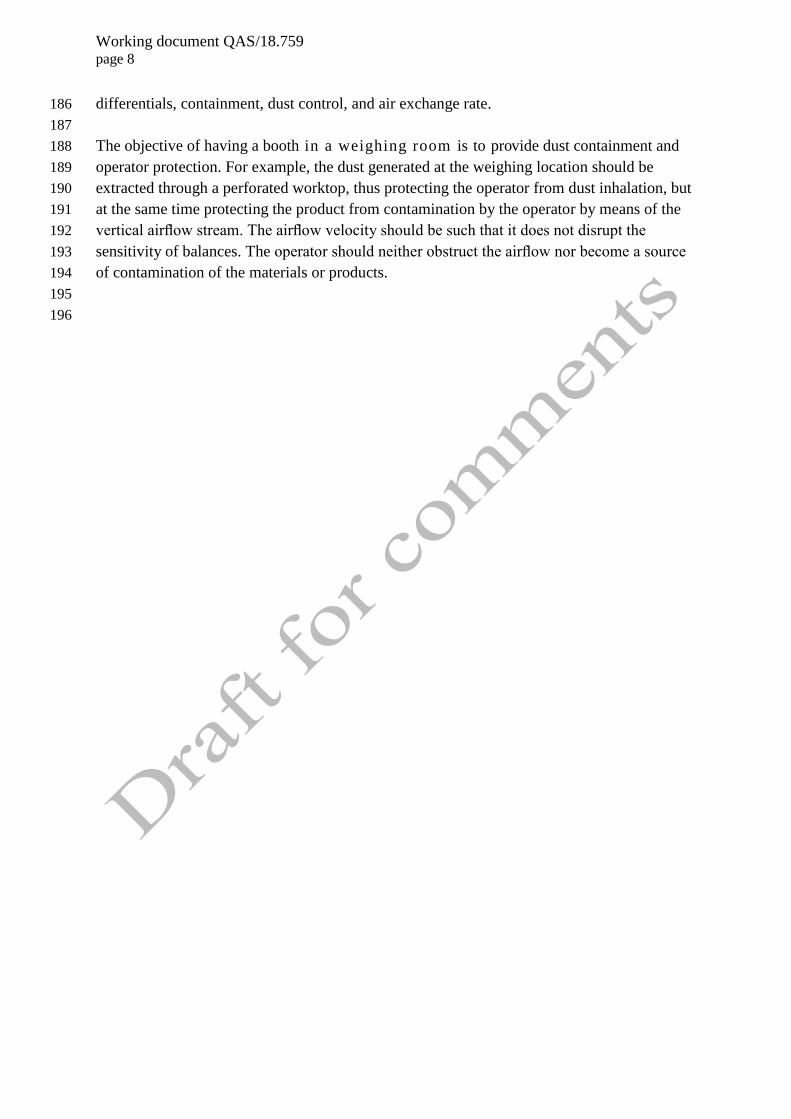
Figure 2. Example of a weighing area 200
201
Dispensary Pre-Staging Room
Weigh
Booth 1
Re
turn
Air S
ha
ft
Airflow
Protection
Plenum
Dispensary
Post-Staging
Room
Wash
BayMAL
MALChange
Room
Weigh
Booth 2
Re
turn
Air S
ha
ft
Airflow
Protection
Plenum
Wash
BayMAL
MALChange
Room
Production Passage
Wa
reh
ou
se
Are
a
Brocken
Bulk
Store
MAL
MALMaterial Flow
202
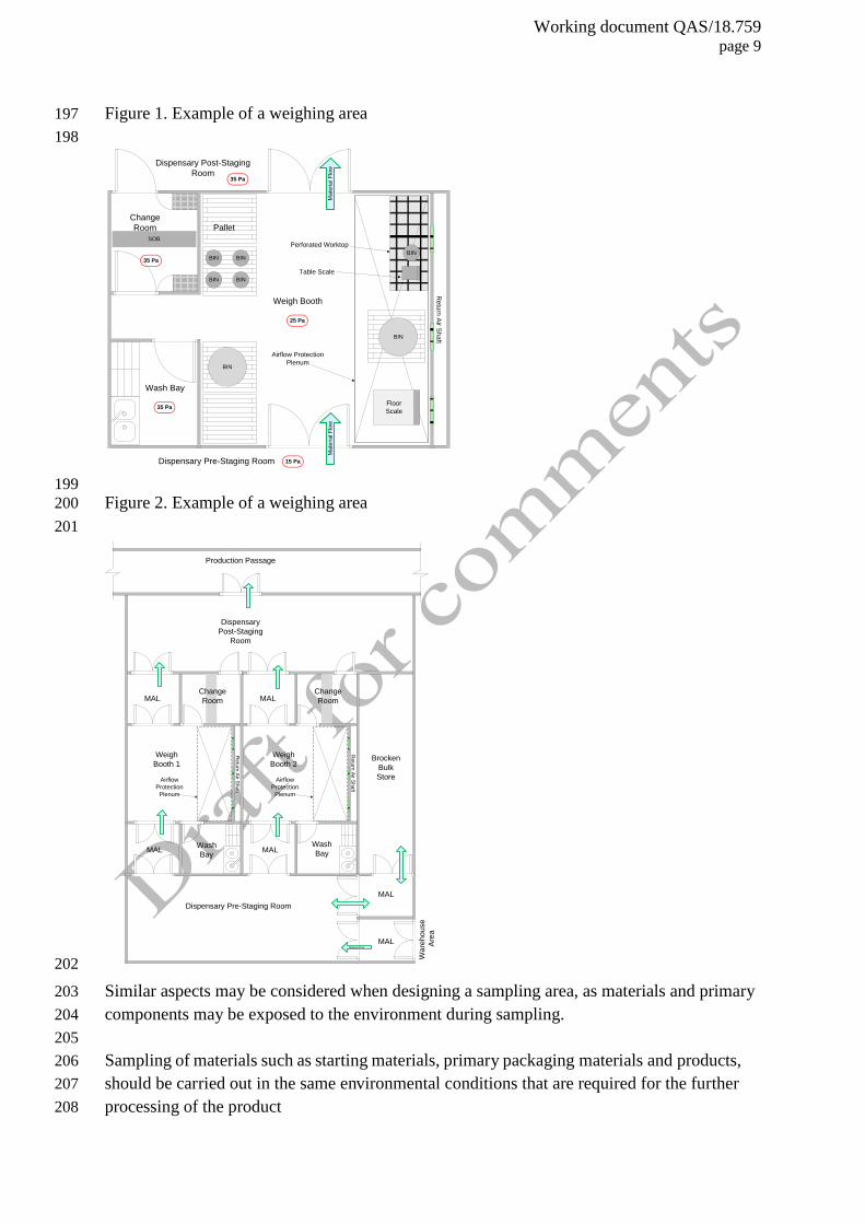
Similar aspects may be considered when designing a sampling area, as materials and primary 203
components may be exposed to the environment during sampling. 204
205
Sampling of materials such as starting materials, primary packaging materials and products, 206
should be carried out in the same environmental conditions that are required for the further 207
processing of the product 208
Working document QAS/18.759 page 10
Figure 3. Example of a sampling area 209
SO
B
Change
Room
Sampling
Booth
Wash Bay
Re
turn
Air S
ha
ft
Airflow Protection
Booth Plenum
PTH
Warehouse
Area30 Pa
15 Pa
25 Pa
5 Pa
Material Flow
Material Flow
Perforated
Worktop
210
211
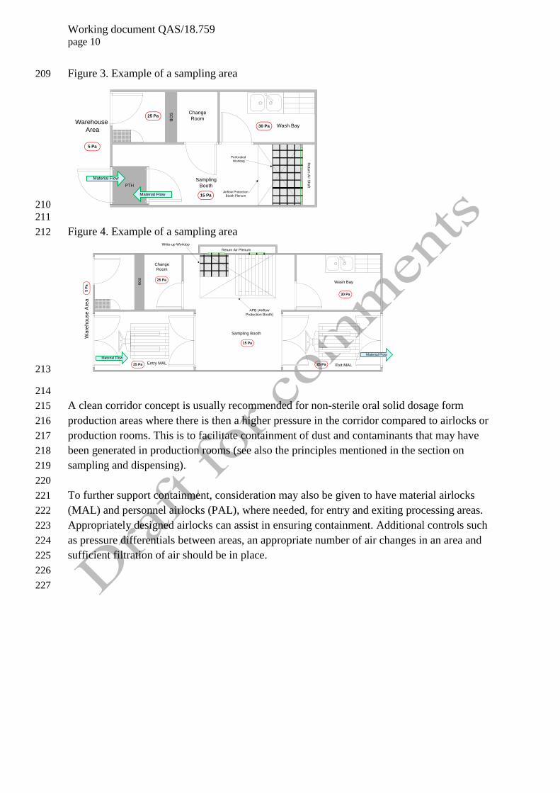
Figure 4. Example of a sampling area 212
SO
B
Entry MAL
Change
Room
Sampling Booth
Wash Bay
Write-up Worktop
APB (Airflow
Protection Booth)
Exit MAL
Return Air Plenum
Material Flow
25 Pa
15 Pa
30 Pa
25 Pa 25 Pa
Material Flow
Wa
reh
ou
se
Are
a5
Pa
213
214
A clean corridor concept is usually recommended for non-sterile oral solid dosage form 215
production areas where there is then a higher pressure in the corridor compared to airlocks or 216
production rooms. This is to facilitate containment of dust and contaminants that may have 217
been generated in production rooms (see also the principles mentioned in the section on 218
sampling and dispensing). 219
220
To further support containment, consideration may also be given to have material airlocks 221
(MAL) and personnel airlocks (PAL), where needed, for entry and exiting processing areas. 222
Appropriately designed airlocks can assist in ensuring containment. Additional controls such 223
as pressure differentials between areas, an appropriate number of air changes in an area and 224
sufficient filtration of air should be in place. 225
226
227

Working document QAS/18.759 page 11
Figure 5. Example of a change room and some production areas 228
SOB
Male
Change
Room
SOB
Female
Change
Room
Lobby
Female
Ablution
Male
Ablution
Production
Passage
0 Pa
15 Pa
15 Pa-10 Pa
-10 Pa
30 Pa
Un-classified Zone
229
Figure 6. Example of a compression cubicle with MAL and PAL (also used as an area to 230
change garments) 231
Compression
Cubicle
Change
Room
MAL
Pa
ssa
ge
Low Level
Return A
ir
Low L
evel
Ret
urn
Air
SO
B
25 Pa
35 Pa
25 Pa
15 Pa
Supply
Air
Grille
232
233
Working document QAS/18.759 page 12
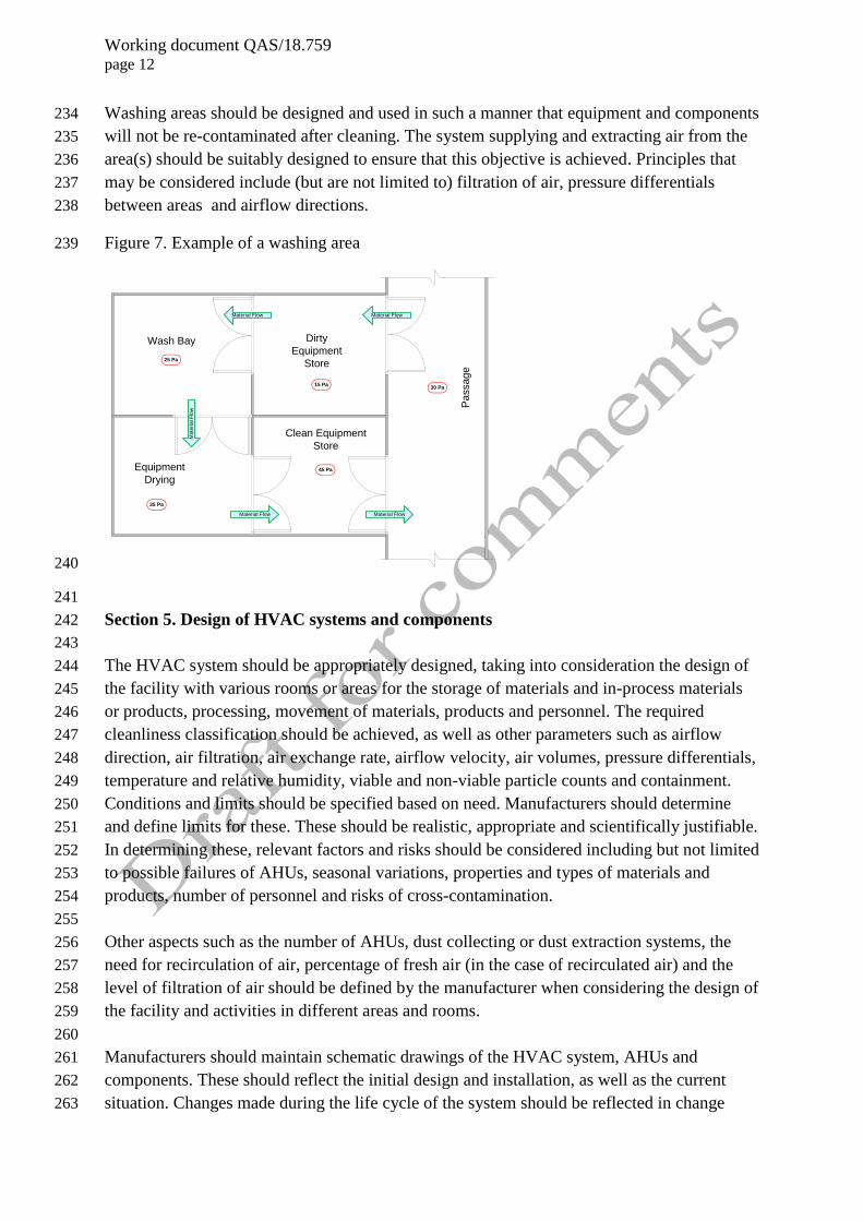
Washing areas should be designed and used in such a manner that equipment and components 234
will not be re-contaminated after cleaning. The system supplying and extracting air from the 235
area(s) should be suitably designed to ensure that this objective is achieved. Principles that 236
may be considered include (but are not limited to) filtration of air, pressure differentials 237
between areas and airflow directions. 238
Figure 7. Example of a washing area 239
Dirty
Equipment
Store
Wash Bay
Pa
ssa
ge
15 Pa30 Pa
45 Pa
35 Pa
Clean Equipment
Store
Equipment
Drying
Material Flow Material Flow
25 Pa
Ma
teria
l F
low
Material Flow Material Flow
240
241
Section 5. Design of HVAC systems and components 242
243
The HVAC system should be appropriately designed, taking into consideration the design of 244
the facility with various rooms or areas for the storage of materials and in-process materials 245
or products, processing, movement of materials, products and personnel. The required 246
cleanliness classification should be achieved, as well as other parameters such as airflow 247
direction, air filtration, air exchange rate, airflow velocity, air volumes, pressure differentials, 248
temperature and relative humidity, viable and non-viable particle counts and containment. 249
Conditions and limits should be specified based on need. Manufacturers should determine 250
and define limits for these. These should be realistic, appropriate and scientifically justifiable. 251
In determining these, relevant factors and risks should be considered including but not limited 252
to possible failures of AHUs, seasonal variations, properties and types of materials and 253
products, number of personnel and risks of cross-contamination. 254
255
Other aspects such as the number of AHUs, dust collecting or dust extraction systems, the 256
need for recirculation of air, percentage of fresh air (in the case of recirculated air) and the 257
level of filtration of air should be defined by the manufacturer when considering the design of 258
the facility and activities in different areas and rooms. 259
260
Manufacturers should maintain schematic drawings of the HVAC system, AHUs and 261
components. These should reflect the initial design and installation, as well as the current 262
situation. Changes made during the life cycle of the system should be reflected in change 263

Working document QAS/18.759 page 13
control records and qualification protocols and reports as appropriate. 264
265
The components selected in an HVAC system should be of sufficient capacity to ensure that 266
the design objectives are met (e.g. for heating, cooling, humidification, dehumidification, air 267
flow volumes), taking impacting factors into consideration such as loss of air due to leakage 268
and seasonal variations. Materials of construction for components and their placement should 269
be such that these do not become the source of contamination. For example, components 270
should not shed particles and the sequence of components should be logical, e.g. filters 271
should be placed in such a manner that any possible contaminants generated in the system 272
can be retained by filters and not be introduced into the production area. 273
274
To prevent contamination of areas, access to components such as ventilation dampers, filters 275
and other services should be accessible from outside the manufacturing areas (such as service 276
corridors). 277
278
The overall design should be such that there is no possibility of undesired, unfiltered air or 279
contaminants entering into manufacturing areas. 280
Containment 281
282
Manufacturers should ensure that appropriate measures are taken to contain product dust in a 283
manufacturing area, thus preventing or minimizing the risk of contamination of other areas 284
and possible cross-contamination. In some cases, it may be advisable to have airlocks or pass 285
through hatches between rooms or areas. In addition, sufficient dilution, pressure differentials 286
(recommended minimum values of 5 to 15 Pa) and airflow directions can further support 287
containment in an area. 288
289
Cleanliness 290
291
Areas should be maintained at the defined levels of cleanliness and classifications. The 292
HVAC system can support this through, e.g. appropriate levels of filtration of air, airflow 293
directions, dilution, dust removal and air exchange rate. Equipment, containers, personnel and 294
other related components should be appropriately located or placed in areas so as not to 295
obstruct airflow and effectiveness of the HVAC system. 296
297
Recontamination should be prevented by ensuring that material and personnel movement is 298
within the same area classification and not back and forth between areas of different 299
classification. Where such back-and-forth movement is unavoidable, appropriate controls 300
should be identified and implemented to ensure that moving from a higher class to a lower 301
classified area and back to a higher classified area will not result in contaminants being 302
brought into the cleaner classified area. 303
304
Automated monitoring systems 305
306

Working document QAS/18.759 page 14
The performance of the HVAC system achieving and maintaining the desired results for 307
parameters such as temperature, relative humidity, airflow and pressure differential should be 308
carefully controlled and monitored. This is to ensure that there is no departure from these 309
limits during manufacturing. Monitoring systems should be in place to ensure that the system 310
operates within its design limits. Manual or automated (computerized) systems may be used. 311
312
Manual systems of monitoring may not always provide sufficient proof that the system is able 313
to maintain all conditions throughout the manufacturing period. 314
315
Automated monitoring systems may provide ongoing monitoring possibilities with better 316
assurance of compliance with the defined limits. Where these automated systems are 317
considered to be GXP systems, these should be appropriately validated. The scope and extent 318
of validation of the computerized system should be determined, be justifiable and 319
appropriately executed. This includes, but is not limited to, access and privileges to the 320
software, setting of limits, monitoring and acknowledging alarms, audit trails, controls, 321
monitoring and reporting. 322
323
Switching off of AHUs 324
325
It is recommended that the HVAC system be operational on an ongoing basis. Where a 326
manufacturer decides to use energy saving modes or switch some selected AHUs off at 327
specified intervals such as overnight, weekends or extended periods of time, care should be 328
taken to ensure that materials and products are not affected. In such cases, the decision, 329
procedures and records should be sufficiently documented and should include risk 330
assessment, standard operating procedures (SOPs), records and validation. This includes 331
procedures and records for the start-up and shut-down sequence of air handling units. 332
333
Section 6. Full fresh air and recirculation systems 334
335
Manufacturers may select to have full fresh air systems or recirculate treated air supplied to 336
production areas (In a full fresh air system, no air is recirculated. In recirculation systems, a 337
defined percentage of the air is recirculated.). In both cases, the air supplied to the production 338
areas should be appropriately treated to ensure that the environmental conditions specified are 339
met and that the risks for contamination and cross-contamination are controlled. 340
341
Manufacturers using recirculation systems should determine the percentage of fresh air to be 342
supplied to the relevant manufacturing areas, as required by national and international 343
standards. This volume of air should be verified during qualification. 344
345
In both scenarios, appropriate levels of filtration should be applied to prevent contamination 346
and cross-contamination. Manufacturers should ensure that when HEPA filters are used that 347
these are appropriately installed, not damaged and thus suitable for the intended use (see tests 348
described below under the section of qualification). 349
350
Working document QAS/18.759 page 15
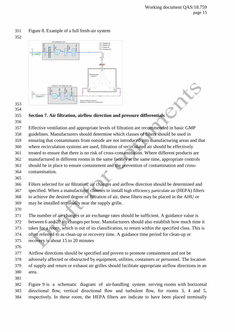
Figure 8. Example of a full fresh-air system 351
352
PRODUCTION
FACILITY
Prim
ary
Filt
er
Exh
au
st A
ir
Fa
n
Se
co
nd
ary
Filt
er
HE
PA
F
ilte
r
EXHAUST AIR HANDLING UNIT
Fresh Air
Exhaust Air
Degree of filtration required
depends on exhaust air contaminants
Prim
ary
Filt
er
Su
pp
ly A
ir
Fa
n
Se
co
nd
ary
Filt
er
HE
PA
F
ilte
r
AIR HANDLING UNIT
Co
olin
g C
oil
-
S
S
R
F
= Supply Air
= Return Air
= Fresh Air
F
S
E = Exhaust Air
E E
E
+
353
354
Section 7. Air filtration, airflow direction and pressure differentials 355
356
Effective ventilation and appropriate levels of filtration are recommended in basic GMP 357
guidelines. Manufacturers should determine which classes of filters should be used in 358
ensuring that contaminants from outside are not introduced into manufacturing areas and that 359
where recirculation systems are used, filtration of recirculated air should be effectively 360
treated to ensure that there is no risk of cross-contamination. Where different products are 361
manufactured in different rooms in the same facility at the same time, appropriate controls 362
should be in place to ensure containment and the prevention of contamination and cross-363
contamination. 364
365
Filters selected for air filtration, air changes and airflow direction should be determined and 366
specified. When a manufacturer chooses to install high efficiency particulate air (HEPA) filters 367
to achieve the desired degree of filtration of air, these filters may be placed in the AHU or 368
may be installed terminally near the supply grille. 369
370
The number of air changes or air exchange rates should be sufficient. A guidance value is 371
between 6 and 20 air changes per hour. Manufacturers should also establish how much time it 372
takes for a room, which is out of its classification, to return within the specified class. This is 373
often referred to as clean-up or recovery time. A guidance time period for clean-up or 374
recovery is about 15 to 20 minutes 375
376
Airflow directions should be specified and proven to promote containment and not be 377
adversely affected or obstructed by equipment, utilities, containers or personnel. The location 378
of supply and return or exhaust air grilles should facilitate appropriate airflow directions in an 379
area. 380
381
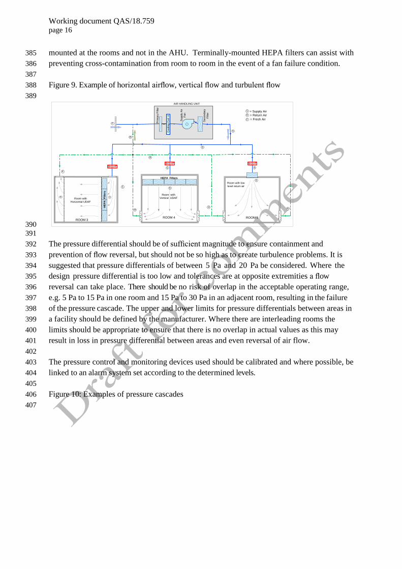
Figure 9 is a schematic diagram of air-handling system serving rooms with horizontal 382
directional flow, vertical directional flow and turbulent flow, for rooms 3, 4 and 5, 383
respectively. In these room, the HEPA filters are indicate to have been placed terminally 384
Working document QAS/18.759 page 16
mounted at the rooms and not in the AHU. Terminally-mounted HEPA filters can assist with 385
preventing cross-contamination from room to room in the event of a fan failure condition. 386
387
Figure 9. Example of horizontal airflow, vertical flow and turbulent flow 388
389
Prim
ary
Filt
er
Su
pp
ly A
ir
Fa
n
Se
co
nd
ary
Filt
er
AIR HANDLING UNIT
Room with
Vertical UDAFRoom with
Horizontal UDAF
ROOM 4ROOM 3
= Supply Air
= Return Air
= Fresh Air
R S
HE
PA
F
ilte
rs
Room with low
level return air
ROOM 5
HEPA Filters
Co
olin
g C
oil
-
S
S
SS
S
F
F
R
R
R
R
R
S
S
S
R
R
+
+ +
390
391
The pressure differential should be of sufficient magnitude to ensure containment and 392
prevention of flow reversal, but should not be so high as to create turbulence problems. It is 393
suggested that pressure differentials of between 5 Pa and 20 Pa be considered. Where the 394
design pressure differential is too low and tolerances are at opposite extremities a flow 395
reversal can take place. There should be no risk of overlap in the acceptable operating range, 396
e.g. 5 Pa to 15 Pa in one room and 15 Pa to 30 Pa in an adjacent room, resulting in the failure 397
of the pressure cascade. The upper and lower limits for pressure differentials between areas in 398
a facility should be defined by the manufacturer. Where there are interleading rooms the 399
limits should be appropriate to ensure that there is no overlap in actual values as this may 400
result in loss in pressure differential between areas and even reversal of air flow. 401
402
The pressure control and monitoring devices used should be calibrated and where possible, be 403
linked to an alarm system set according to the determined levels. 404
405
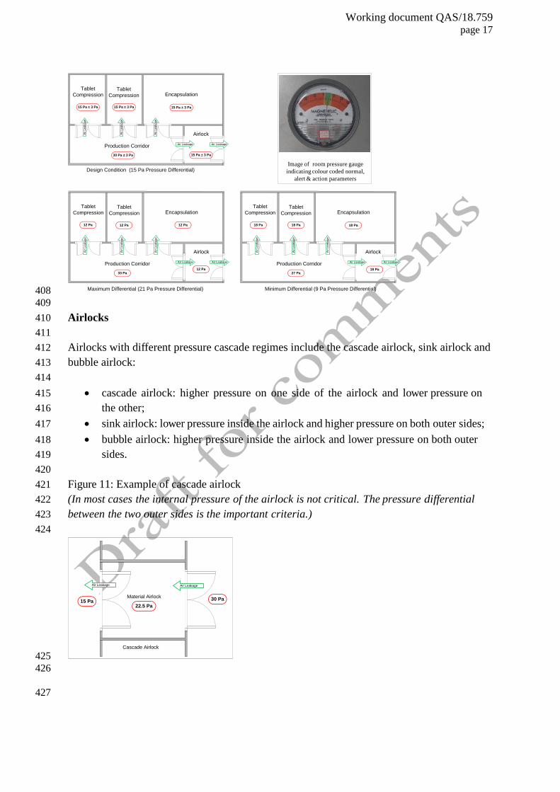
Figure 10: Examples of pressure cascades 406
407
Working document QAS/18.759 page 17
Encapsulation
Airlock
Tablet
Compression
Production Corridor
Design Condition (15 Pa Pressure Differential)
30 Pa ± 3 Pa
15 Pa ± 3 Pa
Tablet
Compression
15 Pa ± 3 Pa15 Pa ± 3 Pa
15 Pa ± 3 Pa
Air Leakage Air Leakage
Air L
ea
ka
ge
Air L
ea
ka
ge
Air L
ea
ka
ge
Encapsulation
Airlock
Tablet
Compression
Production Corridor
33 Pa
Tablet
Compression
12 Pa
Air Leakage Air Leakage
Air L
ea
ka
ge
Air L
ea
ka
ge
Air L
ea
ka
ge
Encapsulation
Airlock
Tablet
Compression
Production Corridor
27 Pa
18 Pa
Tablet
Compression
Air Leakage Air Leakage
Air L
ea
ka
ge
Air L
ea
ka
ge
Air L
ea
ka
ge
Image of room pressure gauge
indicating colour coded normal,
alert & action parameters
Maximum Differential (21 Pa Pressure Differential)
12 Pa 12 Pa
12 Pa
Minimum Differential (9 Pa Pressure Differential)
18 Pa
18 Pa18 Pa
408
409
Airlocks 410
411
Airlocks with different pressure cascade regimes include the cascade airlock, sink airlock and 412
bubble airlock: 413
414
cascade airlock: higher pressure on one side of the airlock and lower pressure on 415
the other; 416
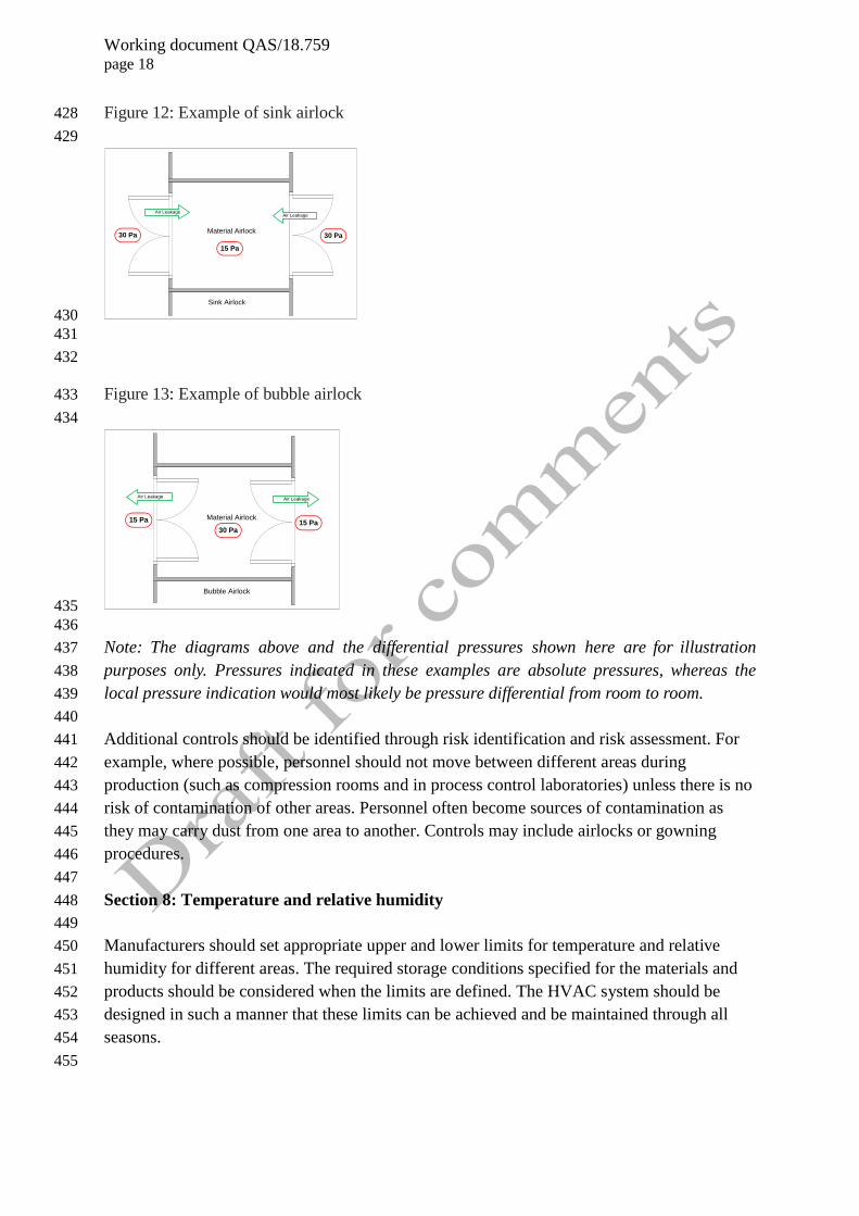
sink airlock: lower pressure inside the airlock and higher pressure on both outer sides; 417
bubble airlock: higher pressure inside the airlock and lower pressure on both outer 418
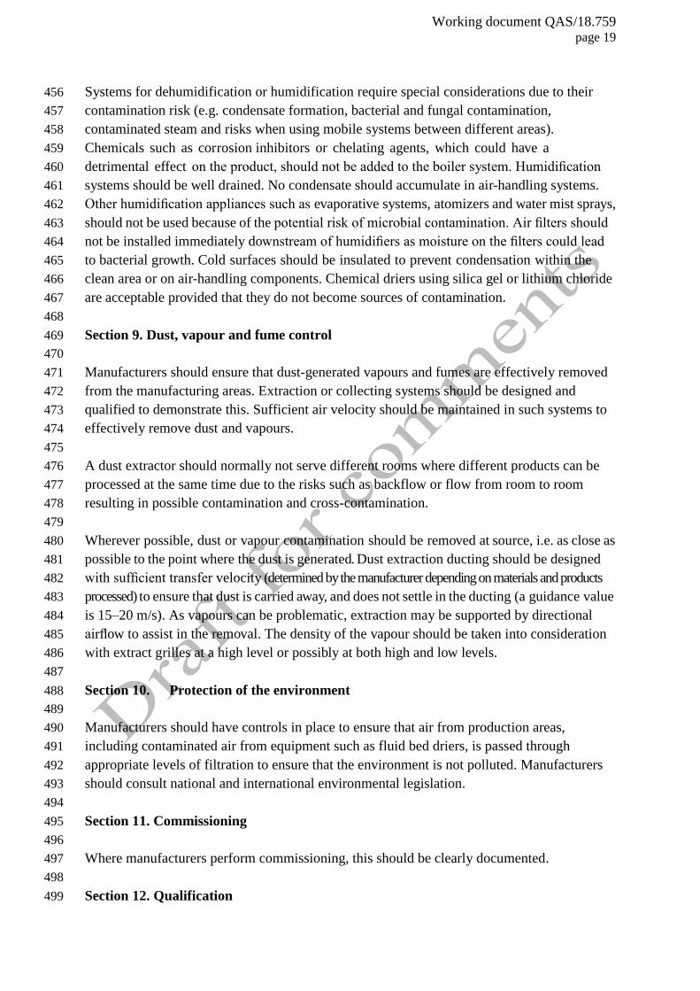
sides. 419
420
Figure 11: Example of cascade airlock 421
(In most cases the internal pressure of the airlock is not critical. The pressure differential 422
between the two outer sides is the important criteria.) 423
424
Material Airlock
Cascade Airlock
Air Leakage Air Leakage
22.5 Pa15 Pa 30 Pa
425
426
427
Working document QAS/18.759 page 18
Figure 12: Example of sink airlock 428
429
Material Airlock
Sink Airlock
Air Leakage Air Leakage
15 Pa
30 Pa30 Pa
430
431
432
Figure 13: Example of bubble airlock 433
434
Material Airlock
Bubble Airlock
Air Leakage Air Leakage
30 Pa15 Pa15 Pa
435
436
Note: The diagrams above and the differential pressures shown here are for illustration 437
purposes only. Pressures indicated in these examples are absolute pressures, whereas the 438
local pressure indication would most likely be pressure differential from room to room. 439
440
Additional controls should be identified through risk identification and risk assessment. For 441
example, where possible, personnel should not move between different areas during 442
production (such as compression rooms and in process control laboratories) unless there is no 443
risk of contamination of other areas. Personnel often become sources of contamination as 444
they may carry dust from one area to another. Controls may include airlocks or gowning 445
procedures. 446
447
Section 8: Temperature and relative humidity 448
449
Manufacturers should set appropriate upper and lower limits for temperature and relative 450
humidity for different areas. The required storage conditions specified for the materials and 451
products should be considered when the limits are defined. The HVAC system should be 452
designed in such a manner that these limits can be achieved and be maintained through all 453
seasons. 454
455
Working document QAS/18.759 page 19
Systems for dehumidification or humidification require special considerations due to their 456
contamination risk (e.g. condensate formation, bacterial and fungal contamination, 457
contaminated steam and risks when using mobile systems between different areas). 458
Chemicals such as corrosion inhibitors or chelating agents, which could have a 459
detrimental effect on the product, should not be added to the boiler system. Humidification 460
systems should be well drained. No condensate should accumulate in air-handling systems. 461
Other humidification appliances such as evaporative systems, atomizers and water mist sprays, 462
should not be used because of the potential risk of microbial contamination. Air filters should 463
not be installed immediately downstream of humidifiers as moisture on the filters could lead 464
to bacterial growth. Cold surfaces should be insulated to prevent condensation within the 465
clean area or on air-handling components. Chemical driers using silica gel or lithium chloride 466
are acceptable provided that they do not become sources of contamination. 467
468
Section 9. Dust, vapour and fume control 469
470
Manufacturers should ensure that dust-generated vapours and fumes are effectively removed 471
from the manufacturing areas. Extraction or collecting systems should be designed and 472
qualified to demonstrate this. Sufficient air velocity should be maintained in such systems to 473
effectively remove dust and vapours. 474
475
A dust extractor should normally not serve different rooms where different products can be 476
processed at the same time due to the risks such as backflow or flow from room to room 477
resulting in possible contamination and cross-contamination. 478
479
Wherever possible, dust or vapour contamination should be removed at source, i.e. as close as 480
possible to the point where the dust is generated. Dust extraction ducting should be designed 481
with sufficient transfer velocity (determined by the manufacturer depending on materials and products 482
processed) to ensure that dust is carried away, and does not settle in the ducting (a guidance value 483
is 15–20 m/s). As vapours can be problematic, extraction may be supported by directional 484
airflow to assist in the removal. The density of the vapour should be taken into consideration 485
with extract grilles at a high level or possibly at both high and low levels. 486
487
Section 10. Protection of the environment 488
489
Manufacturers should have controls in place to ensure that air from production areas, 490
including contaminated air from equipment such as fluid bed driers, is passed through 491
appropriate levels of filtration to ensure that the environment is not polluted. Manufacturers 492
should consult national and international environmental legislation. 493
494
Section 11. Commissioning 495
496
Where manufacturers perform commissioning, this should be clearly documented. 497
498
Section 12. Qualification 499
Working document QAS/18.759 page 20
500
Manufacturers should consider all stages of qualification for their HVAC systems. This 501
includes, where appropriate, user requirement specification, design qualification, factory 502
acceptance test, site acceptance test, installation qualification, operational qualification and 503
performance qualification. Qualification to be done over the life cycle of the HVAC system 504
should be described and executed including, e.g. when changes are made to the system. 505
506
Validation master plan(s), protocols, reports and source data for tests should be available. The 507
scope and extent of qualification should be determined based on risk assessment. Parameters 508
with limits included in qualification (such as temperature test, airflow direction, viable and 509
non-viable particle counts) should be justified by manufacturers. The procedures followed for 510
the performance of the tests should generally be in line with the standard as described in ISO 511
14644 512
513
Some of the typical HVAC system parameters that should be included in the tests during 514
qualification are listed below. It is recommended that the tests be done at defined intervals. 515
The tests typically cover: 516
517
— temperature; 518
— relative humidity; 519
— supply air quantities; 520
— return air or exhaust air quantities; 521
— room air-change rates; 522
— pressure differentials; 523
— airflow direction test; 524
— installed filter leakage tests; 525
— particle counts; 526
— clean-up or recovery rates; 527
— microbiological counts; 528
— warning/alarm systems. 529
530
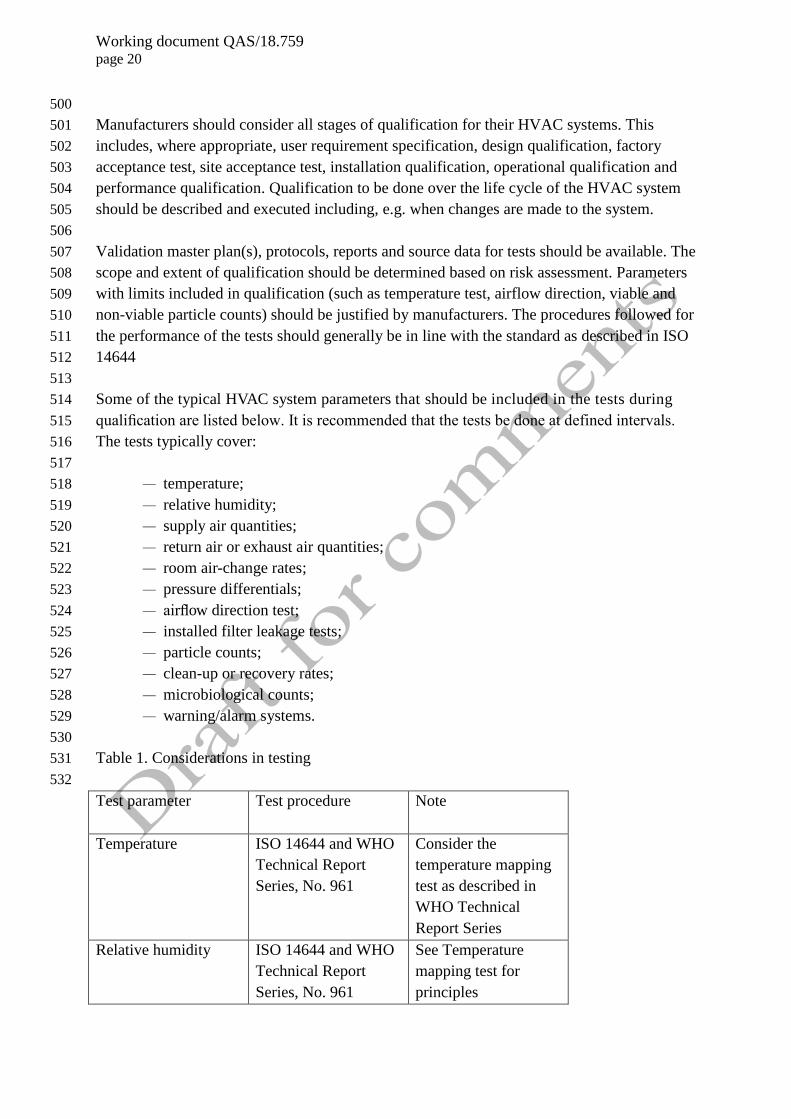
Table 1. Considerations in testing 531
532
Test parameter
Test procedure Note
Temperature ISO 14644 and WHO
Technical Report
Series, No. 961
Consider the
temperature mapping
test as described in
WHO Technical
Report Series
Relative humidity ISO 14644 and WHO
Technical Report
Series, No. 961
See Temperature
mapping test for
principles
Working document QAS/18.759 page 21
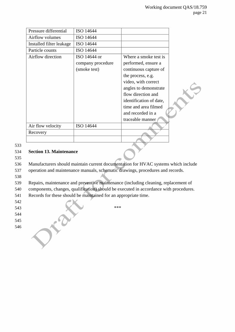
Pressure differential ISO 14644
Airflow volumes ISO 14644
Installed filter leakage ISO 14644
Particle counts ISO 14644
Airflow direction ISO 14644 or
company procedure
(smoke test)
Where a smoke test is
performed, ensure a
continuous capture of
the process, e.g.
video, with correct
angles to demonstrate
flow direction and
identification of date,
time and area filmed
and recorded in a
traceable manner
Air flow velocity ISO 14644
Recovery
533
Section 13. Maintenance 534
535
Manufacturers should maintain current documentation for HVAC systems which include 536
operation and maintenance manuals, schematic drawings, procedures and records. 537
538
Repairs, maintenance and preventive maintenance (including cleaning, replacement of 539
components, changes, qualification) should be executed in accordance with procedures. 540
Records for these should be maintained for an appropriate time. 541
542
*** 543
544
545
546