GOLDENVAC STAINLESS STEEL VACUUM PUMP - … · GOLDENVAC STAINLESS STEEL PUMP INSTALLATION 1....
32
2625 N. Argyle Ave. • Fresno, CA 93727 (559) 291-1650 • (800) 428-7139 • FAX (559) 348-9677 TECH WEST INC. Manufacturers of Dental Vacuum and Air Systems GOLDENVAC STAINLESS STEEL VACUUM PUMP INSTALLATION AND SERVICE MANUAL Revised 8-08
Transcript of GOLDENVAC STAINLESS STEEL VACUUM PUMP - … · GOLDENVAC STAINLESS STEEL PUMP INSTALLATION 1....

2625 N. Argyle Ave. • Fresno, CA 93727(559) 291-1650 • (800) 428-7139 • FAX (559) 348-9677
TECH WEST INC.Manufacturers of Dental Vacuum
and Air Systems
GOLDENVAC STAINLESS STEELVACUUM PUMP
INSTALLATIONAND SERVICE
MANUAL Revised 8-08

.
1
GOLDENVACSTAINLESS STEEL PUMP
INSTALLATION AND SERVICE MANUALThis manual is for the installation and service of Tech West’s GoldenVac Pumps.
CONTENTS
Installation 2
Figure 1: Plumbing Schematic 4
Figure 2: Water Connection 4
Figure 3: Typical Dual GoldenVac Installation 5
Figure 4: Sink Cabinet Installation 5
Figure 5: Vacuum Connection - Single GoldenVac 6
Figure 6: Vacuum Connection - Dual GoldenVac 6
Figure 7: Wiring Diagram 7
Figure 8: Remote Control Wiring 7
Figure 9: Line Voltage Connection 8
Weekly Servicing 9
Parts List 10-16
TROUBLESHOOTING
Single Vacuum Pump Troubleshooting 18-19
Dual Vacuum Pump Troubleshooting 20-21
Triple Vacuum Pump Troubleshooting 22-23
Installation Diagrams and Information 24-26
Maintenance & Service and Notes Sheet 27-29

GOLDENVAC STAINLESS STEEL PUMPINSTALLATION
1. GOLDENVAC LOCATION REQUIREMENTS
The GoldenVac location should be level, accessible and well ventilated.
If the GoldenVac will be located in a confined space, provide cross ventilation and install an exhaust fan.
The following utilities are required:
(a) Cold Water Supply Install a separate 1/2” cold water branch for the GoldenVac water intake(s). This will cool and lubricate the shaft seal. Water pressure should be between 25 and 55 psi (water must remain on during operation) or shaft seal damage will occur.
(b) Waste Disposal The GoldenVac will exhaust both vapor and liquid waste. Provide exhaust vent sized to 2” in diameter and a waste drain which complies with local code.
(c) Vacuum Line The main vacuum line from the operatories must connect to the GoldenVac vacuum pump intake manifold.
(d) Electrical
(1) Line voltage must be within the limits of table 1 below. (Install a “buck-boost transformer” if line voltage is not between these values.) Provide a separate line for each pump motor. Circuit breaker switches must be 20 amp.
(2) Local code may require you to provide one quick disconnect (safety switch) for each pump motor.
(3) The GoldenVac is controlled by a 24 volt circuit. For remote control, provide one 18/3 jacketed cable for each pump motor.
2
PUMP VOLTAGE RATING
230 v
115 v
MIN VOLTAGE RATING
208 v constant
110 v constant
MAX VOLTAGE RATING
240 v constant
130 v constant
TABLE 1

GOLDENVAC PUMPINSTALLATION
2
2. INSTALLATION STEPS
(a) Check the shipping carton for damage. This could detect damage to the unit which might otherwise be overlooked.
(b) Remove the GoldenVac from its shipping carton. Inspect the unit for damage. (Single GoldenVac’s are shipped bolted to a pallet. This pallet is intended for shipping use only and should be discarded).
(c) Inventory your Hook-Up Kit. Check its contents against the inventory sheet included. These items will be used in the remaining steps.
(d) Mount the GoldenVac. To dampen vibration, ensure rubber isolators are installed on each WhirlWind Pump.
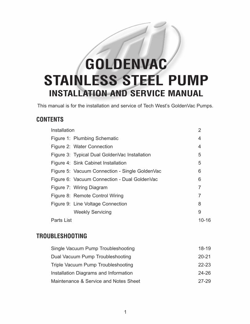
Refer to the schematic diagram of Figure 1 for steps (e) (f) and (g).
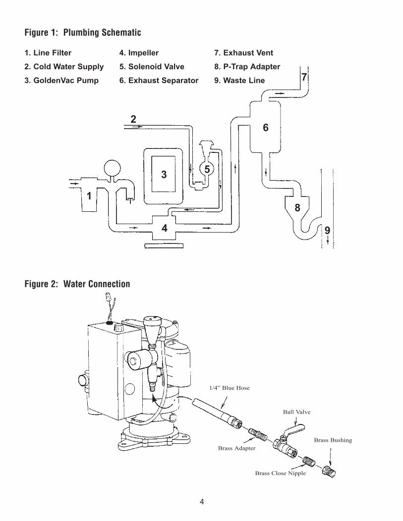
(e) Connect the cold water supply. See Figure 2. Turn the water on and check for leaks in the water control assembly.
(f) Make the necessary waste connections. Figures 3 and 4 show typical installations. To install a Tech West Exhaust Separator or Water Recycler see the applicable installation sheet.
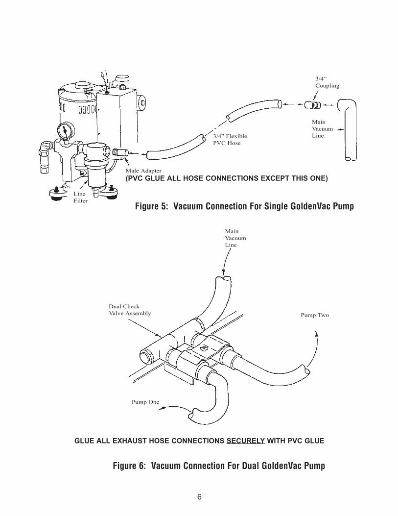
(g) Connect the main vacuum line. For Single GoldenVac’s, connect flexible hose to the pump intake manifold (Figure 5). For Dual and Triple GoldenVac’s, connect to the vacuum intake manifold(Figure 6).
Refer to the wiring diagram of Figure 7 for steps (h) and (I). Detailed wiring diagrams are on the inside of each pump relay panel cover plate.
(h) Connect remote control 18/3 jacketed cable to each pump relay panel. Use wire connectors which provide secure mechanical connections. See Figure 8.
(i) Connect to line voltage (via safety switch(es) if required by local code). Use 12 gauge THHN grade wire and approved conduit for permanent wiring. See Figure 9. (Single GoldenVac pumps may operate on either 115 volt or 230 volt lines. For terminal changing instructions see inside of relay panel cover plate.
(j) Turn on the GoldenVac. Check the pump(s) for leaks and the vacuum level following the instruction in “Weekly Servicing” page 8.
3
4
7
6
8
9
53
4
2
1
1/4” Blue Hose
Ball Valve
Brass Adapter
Brass Close Nipple
Brass Bushing
Figure 1: Plumbing Schematic
1. Line Filter 4. Impeller 7. Exhaust Vent
2. Cold Water Supply 5. Solenoid Valve 8. P-Trap Adapter
3. GoldenVac Pump 6. Exhaust Separator 9. Waste Line
Figure 2: Water Connection

5
Ventilation
FloorSink
ExhaustSeparator
FromOperatory
Fan
ExhaustVent
Cold WaterSupply
MainVacuumLine
SafetySwitch
Safety Switch
ExhaustVent
ExhaustSeparator
ColdWaterSupply
P-TrapAdapter
Figure 3: Typical Dual GoldenVac Vacuum Installation
Figure 4: Sink Cabinet Installation
6
Figure 5: Vacuum Connection For Single GoldenVac Pump
Figure 6: Vacuum Connection For Dual GoldenVac Pump
GLUE ALL EXHAUST HOSE CONNECTIONS SECURELY WITH PVC GLUE
Pump One
Dual CheckValve Assembly
MainVacuumLine
Pump Two
3/4” FlexiblePVC Hose
Main VacuumLine
3/4” Coupling
Male Adapter
(PVC GLUE ALL HOSE CONNECTIONS EXCEPT THIS ONE)
LineFilter

7
RelayPanel
WireConnectors
ToRemoteControlPanel
230 v
SafetySwitches
18/3JacketedCable
CircuitBreaker
230 v
230 v
Nuet
24 V Remote Control Panel
GoldenVac One
GoldenVac Two
24 VRemoteControlRelay
24 VRemoteControlRelay
Sol.Valve
Sol.Valve
MotorMotor
Figure 8: Remote Control Wiring
Figure 7: Wiring Diagram
Wiring Diagram Illustrates The Connections For a Dual GoldenVac Pump

8
Figure 9: Line Voltage Connections
ConduitFromSafetySwitch
GroundConnection
TerminalBoard
RelayBox
MotorLeads
LoadOut
LineIn
LoadOut
LineIn

GOLDENVAC PUMPWEEKLY SERVICING
3.WEEKLY SERVICING
(a) Clean vacuum filter bowl and screen. Turn the pump off and unscrew the vacuum filter bowl, rinse bowl and screen under cold water. Replace bowl or screen if damaged. Ensure gasket is in place in the filter bowl before reassembly.
(b) Flush the GoldenVac pump(s) and main vacuum lines with a non-foaming dental vacuum cleanser. Follow the cleanser manufacturer’s instructions.
(c) Visually inspect GoldenVac pump(s) for water leakage. Ensure that all hose clamps and waterconnections are tight.
(d) Check vacuum gauge level. Vacuum settings are adjusted at the factory according to table 3 below. To check the vacuum level, ensure that the pump is aspiring air only. If the vacuum level is out of adjustment, turn off the pump and remove the vacuum relief valve. Holding the phillips head screw in place, turn the “tension nut”.
One complete clock-wise turn of the tension nut will add 2 in. hg. to the vacuum level; one complete counter-clock-wise turn will subtract 2 in. hg. from the vacuum level.
WARNING: NEVER SET VACUUM LEVEL HIGHER THAN INDICATED IN TABLE 3
Flush the entire vacuum piping system (all operatories) weekly. Use a non-foaming cleanser. If the GoldenVac cannot induce adequate air flow because of a blockage in the vacuum piping system, liquids and solids will not evacuate. Contact Tech West’s Customer Service for further details on maintaining your vacuum piping system.
9
GOLDENVAC(HORSEPOWER)
AIR ASPIRATION VACUUM LEVEL
(INCHES OF MERCURY)
TABLE 3
2
12

10
2
4
5
7
9
8
3
KEY PART NO. DESCRIPTION UNIT
2 WIA-100 WATER INJECTION ASSEMBLY, COMPLETE 1
3 PRC-100 115V/230V RELAY CONTROL BOX, COMPLETE 1
4 SSPH STAINLESS STEEL PUMP HOUSING 1
5 PSS-100 SHAFT SEAL 1
6 SSIL STAINLESS STEEL PUMP IMPELLER 2 HP PUMP 1
7 OR-5 5” RUBBER BASE PLATE ‘0’ RING SEAL 1
8 SSBP STAINLESS STEEL BASE PLATE 1
9 RFV-100 RUBBER FEET FOR VACUUM PUMP 3
GOLDENVAC PUMP 2 HP
6

11
KEY PART NO. DESCRIPTION UNIT
11 PVB-100 1/4” VACUUM BREAKER 1
12 BRN-4-2 1/4” MPT x 1/8” MPT NIPPLE 1
13 PSV-115GC 115V 1/8” SOLENOID VALVE/COIL 1
14 BN-125-CL 1/8” BRASS CLOSE NIPPLE 1
15 VPS-125 1/8” WATER STRAINER 1
16 WIN 1/4” MPT INJECTION NOZZLE 1
17 PRT-250 1/4” BLUE POLY TUBE PER. FT
18 WIN-RP 1/4” MPT INJECTION NOZZLE (FOR RECYCLERS ONLY) 1
WATER INJECTION ASSEMBLY
15
14
13
12
11
17
16
18

12
GOLDENVAC MANIFOLD AND FILTER
KEY PART NO. DESCRIPTION UNIT
18 VPG-100 30” HG GAUGE 1
19 BN-750-CL 3/4” BRASS CLOSE NIPPLE 1
20 VFA-40 3/4” FILTER UNIT, COMPLETE 1
21 VFG-100 3/4” RUBBER GASKET FOR BOWL 3
22 VFS-40 40 MESH SCREEN FOR 3/4” FILTER 3
23 MG-100 MANIFOLD GASKET 1
24 VRV-100 VACUUM RELIEF VALVE W/ FITTING 1
25 VFB-100 3/4” VACUUM FILTER BOWL 1
26 SPMA-100 STAINLESS STEEL PUMP MANIFOLD ASSEMBLY 1
20
21
22
25
24
19
23
18

13
KEY PART NO. DESCRIPTION UNIT
27 FH-100 FUSE HOLDER, PUMP 1
28 SBF-100 1/4 AMP MDL FUSES 5
29 PT-100 24V TRANSFORMER, 30A 1
30 PR-100 24V RELAY CONTACTOR 1
- RC-115 115V RELAY CONTROL, COMPLETE 1
- RC-230 230V RELAY CONTROL, COMPLETE 1
LOW VOLTAGE RELAY CONTROL BOX
27
28
29
30

14
KEY PART NO. DESCRIPTION UNIT
32 RFV-100 RUBBER FEET FOR VACUUM PUMP 3
33 PTA-100 P-TRAP ASSEMBLY 1
34 ES-1 EXHAUST SEPARATOR TANK 1
SINGLE GOLDENVAC
34
32
33
SINGLE PUMP UNITS REQUIREEXHAUST SEPARATOR TANKTO MOUNT TO A WALL.

15
KEY PART NO. DESCRIPTION UNIT
35 BV-250 1/4” BALL VALVE / FRESH WATER SUPPLY 2
36 RFV-100 RUBBER FEET FOR VACUUM PUMP 4
37 DCV-100 DUAL CHECK VALVE ASSEMBLY 1
38 PTA-100 P-TRAP ASSEMBLY 1
39 ES-2 EXHAUST SEPARATOR TANK 1
DUAL GOLDENVAC PLATFORM
38
37
36
39

16
KEY PART NO. DESCRIPTION UNIT
40 BV-250 1/4” BALL VALVE / FRESH WATER SUPPLY 3
41 RFV-100 RUBBER FEET FOR VACUUM PUMP 6
42 TCV-100 TRIPLE CHECK VALVE ASSEMBLY 1
43 PTA-100 P-TRAP ASSEMBLY 1
44 ES-3 EXHAUST SEPARATOR TANK 1
TRIPLE GOLDENVAC PLATFORM
43
44
41
42
17
Maintenance & Service SuppliesService scheduled for: Service items needed:
18
DO
ES
VA
CU
UM
PU
MP
RU
N?
Is t
here
suf
ficie
ntsu
ctio
n?Is
the
re e
xces
sive
vacu
um?
Doe
s pu
mp
run
cont
inuo
usly
?Y
ES
YE
SN
O
Doe
s th
erm
al
prot
ecto
r sh
ut t
hepu
mp
dow
n?
NO
YE
SN
O
Is v
acuu
m r
elie
f fil
ter
clog
ged?
Is v
acuu
m r
elie
f fil
ter
or in
take
stra
iner
scr
een
clog
ged?
Che
ck f
orad
equa
teve
ntila
tion
and
prop
ervo
ltage
.
GO
ON
TO
TH
E N
EX
TP
AG
E.
YE
SC
lean
or
repl
ace
filte
r.
Rep
air
vacu
umle
aks.
YE
SY
ES
Cle
an o
rre
plac
efil
ter.
Are
the
re a
nyva
cuum
leak
s at
the
pum
p?
Is t
he o
ffice
vacu
um p
ipin
gsy
stem
fau
lty?
Is t
he v
acuu
m r
elie
fva
lve
set
too
low
?(N
orm
al le
vel
is 1
0” h
g)
Is t
here
ade
quat
ew
ater
sup
ply
orw
ater
pre
ssur
e?
Is v
acuu
m r
elie
fva
lve
set t
oo h
igh
(abo
ve 1
0” h
g)?
Is c
ircui
t br
eake
rtr
ippi
ng?
Do
rela
y co
ntac
tsre
mai
n cl
osed
?A
djus
t to
10”
hg.
Che
ck
rela
y an
dtr
ansf
orm
er.
Con
tact
Te
chW
est.
Con
tact
Tech
Wes
t.
Adj
ust
to10
” hg
.
NO
NO
NO
NO
NO
NO
NO
NO
Rem
ove
vacu
um in
let
line
from
pum
p.
Ifth
ere
is g
ood
suct
ion
atpu
mp,
but
lit
tle o
r no
nein
sys
tem
,th
e sy
stem
iscl
ogge
d or
cont
ains
le
aks.
YE
S
NO
YE
S
YE
SY
ES
YE
S
CH
EC
K F
OR
:1.
“O
PE
N”
wat
er s
uppl
y va
lve.
2. C
logg
ed w
ater
str
aine
r3.
Clo
gged
wat
er r
egul
ator
4. C
logg
ed r
ecyc
ler
line
5. C
heck
for
pro
per
volta
ge a
tw
ater
sol
enoi
d co
il (i)
(1
15
V M
AX
on
2 hp
).
Rep
lace
sol
enoi
d va
lve
if pr
oper
vol
tage
exi
sts.
NO
Che
ck u
sage
char
ts f
orm
axim
umnu
mbe
r of
sim
ulta
neou
sus
ers.
Upg
rade
ifne
cess
ary.
YE
S
CH
EC
K F
OR
:1.
pro
per
seal
ing
of s
trai
ner
bow
l. (D
) O
-rin
g m
ay b
e pi
nche
d.
2. p
rope
r fu
nctio
ning
va
cuum
rel
ief
valv
e .
(A
) V
alve
may
be
stic
king
op
en.
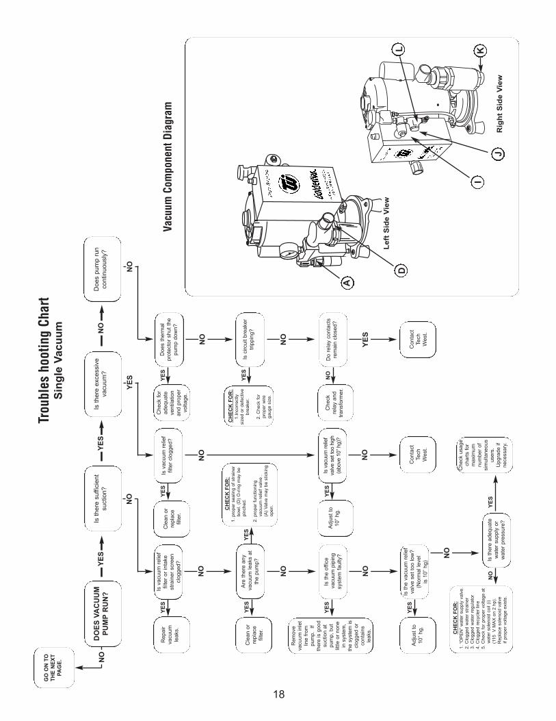
Trou
bles
hoo
ting
Char
tS
ing
le V
acu
um
Vacu
um C
ompo
nent
Dia
gram
YE
S
Le
ft S
ide
Vie
w
Rig
ht
Sid
e V
iew
L K
J
I
D
NO
YE
S
A
CH
EC
K F
OR
:1.
Inco
rrec
tly
size
d or
def
ectiv
e br
eake
r.
2. C
heck
for
pr
oper
wire
gaug
e si
ze.

19
OR
A
WH
T
YE
L/B
LK
BR
N
BL
K
YE
LL
OW
/BL
AC
KO
RA
NG
EW
HIT
E
BL
AC
K
LIN
E I
N
20 A
MP
LIS
TE
DC
IRC
UIT
BR
EA
KE
RR
EQ
UIR
ED
SO
L.
VA
LV
E12
0 V
.
BL
KB
LK
RE
DR
ED
RE
D
BL
K
BLKL
INE
IN
115
V
WHT
WH
T
RED
BLK
BLU
RE
D/
BL
KW
HT
/B
LK
BL
K
BL
UB
LU
24 V
OL
TBLU
RED
WHT
RED/BLK
FU
SE
WHT
RED
AU
X 1
15 V
LE
AD
S
RE
D
MO
TO
R H
AS
AU
XIL
IAR
YO
UT
PU
T L
EA
DS
FO
R11
5 V
OL
T U
SE
BR
N
OR
N
YE
L/B
LK
BL
U
WH
T
YE
LL
OW
/BL
AC
KB
RO
WN
OR
AN
GE
WH
ITE
LIN
E I
N
SO
L.
VA
LV
E12
0 V
.
BL
KB
LK
RE
DR
ED
RE
D
BL
K
BLK
LIN
E I
N
230
V
WHT
WH
T
RED
BLK
BLU
RE
D/
BL
KW
HT
/B
LK
BL
K
BL
UB
LU
24 V
OL
T
BLU
RED
WHT
RED/BLK
FU
SE
WHT
RED
AU
X 1
15 V
LE
AD
S
RE
D
MO
TO
R H
AS
AU
XIL
IAR
YO
UT
PU
T L
EA
DS
FO
R11
5 V
OL
T U
SE
115
VO
LT
230
VO
LT
20 A
MP
LIS
TE
DC
IRC
UIT
BR
EA
KE
RR
EQ
UIR
ED
TR
AN
SF
OR
ME
R L
EA
DS
ST
EP
S T
O C
HA
NG
EV
OLT
AG
E F
RO
M23
0 T
O 1
15 V
MO
VE
RE
D W
IRE
FR
OM
TE
RM
INA
L#8
TO
TE
RM
INA
L#7
AN
D T
HE
WH
ITE
/BL
AC
KF
RO
M T
ER
MIN
AL
#8 T
O #
9.
TH
EN
MO
VE
OR
AN
GE
FR
OM
#4
TO
#3
TH
EN
BL
AC
KF
RO
M #
4 T
O #
6
RE
D
RE
D
RE
D
WH
T/B
LK
WH
T/B
LKW
HT
/BL
K
WH
T/B
LK
RE
D
ST
EP
S T
O C
HA
NG
EV
OLT
AG
E F
RO
M11
5 T
O 2
30 V
MO
VE
RE
D W
IRE
FR
OM
TE
RM
INA
L#7
TO
TE
RM
INA
L#8
AN
DW
HIT
E/B
LA
CK
FR
OM
TE
RM
INA
L#9
TO
TE
RM
INA
L#8
TH
EN
MO
VE
BL
AC
K F
RO
M #
6T
O #
4 T
HE
NM
OV
E T
HE
OR
AN
GE
FR
OM
#3 T
O #
4
DO
ES
VA
CU
UM
PU
MP
RU
N?
YE
S
NO
YE
S
NO
TE
:V
olta
gesh
ould
be
+or
- 1
0% o
fra
ting.
A
lso,
mak
e su
repu
mp
isju
mpe
red
prop
erly
.
GO
TO
TH
EP
RE
VIO
US
PA
GE
.
Is t
here
suf
ficie
ntvo
ltage
at
disc
onne
ct b
ox?
Is t
here
pro
per
volta
ge a
t in
put
term
inal
s?
YE
S
Doe
s re
lay
chat
ter?
YE
S
Doe
s pu
mp
run
with
rem
ote
switc
h-in
g by
pass
ed (
red
& b
lue
low
vol
tage
wire
s co
nnec
ted)
?
NO
Is t
here
suf
ficie
ntvo
ltage
(20
- 2
8V
AC
) be
twee
n th
ebl
ue a
nd r
ed lo
w
volta
ge w
iring
?
YE
S
Do
rela
y co
ntac
tscl
ose?
NO
TE
:M
ake
sure
rem
ote
switc
hing
isby
pass
ed.
Inst
all
Tech
Wes
ttr
ansf
orm
er.
NO
Che
ck f
or
brok
en o
rlo
ose
pow
erlin
e or
ex
cess
ive
vo
ltage
dro
pac
ross
line
.
NO
Low
vol
tage
or im
prop
erly
jum
pere
dpu
mp.
NO
Rep
lace
rem
ote
switc
hor
rep
lace
faul
ty w
iring
.
YE
S
Def
ectiv
efu
se o
r tr
ans-
form
er o
rfa
ulty
con
-ne
ctio
n w
ithin
elec
tric
al b
ox.
NO
Rep
lace
rela
y.N
OY
ES
Con
tact
Tech
Wes
t.
Vacu
um W
irin
g D
iagr
amD
ual
Vo
ltag
eS
ing
le V
acu
um

20
DO
ES
VA
CU
UM
PU
MP
RU
N?
Is t
here
suf
ficie
ntsu
ctio
n?Is
the
re e
xces
sive
vacu
um?
Doe
s pu
mp
run
cont
inuo
usly
?Y
ES
YE
SN
O
Doe
s th
erm
al
prot
ecto
r sh
ut t
hepu
mp
dow
n?
NO
YE
SN
O
Is v
acuu
m r
elie
f va
lve
filte
rcl
ogge
d?
Is v
acuu
m r
elie
fva
lve
filte
r or
inta
kest
rain
er s
cree
ncl
ogge
d or
is s
win
gch
eck
valv
e st
icki
ng?
Che
ck f
orad
equa
teve
ntila
tion
and
prop
ervo
ltage
.
GO
ON
TO
TH
E N
EX
TP
AG
E.
YE
SC
lean
or
repl
ace
filte
r.
Rep
air
vacu
umle
aks.
YE
SY
ES
Cle
an o
rre
plac
efil
ter.
Are
the
re a
ny
vacu
um le
aks
atth
e pu
mp?
Is t
he o
ffice
vacu
um p
ipin
gsy
stem
fau
lty?
Is t
he v
acuu
m r
elie
fva
lve
set
too
low
?(N
orm
al le
vel
is 1
0” h
g)
Is t
here
ade
quat
ew
ater
sup
ply
orw
ater
pre
ssur
e?
Is v
acuu
m r
elie
fva
lve
set t
oo h
igh
(abo
ve 1
0” h
g)?
Is c
ircui
t br
eake
rtr
ippi
ng?
Do
rela
y co
ntac
tsre
mai
n cl
osed
?A
djus
t to
10”
hg.
Che
ck
rela
y an
dtr
ansf
orm
er.
Con
tact
Te
chW
est.
Con
tact
Tech
Wes
t.
Adj
ust
to10
” hg
.
NO
NO
NO
NO
NO
NO
NO
NO
Rem
ove
vacu
um in
let
line
from
pum
p.
Ifth
ere
is g
ood
suct
ion
atpu
mp,
but
‘li
ttle
or n
one
in s
yste
m,
the
syst
em is
clog
ged
orco
ntai
ns
leak
s.
YE
S
NO
YE
S
YE
SY
ES
YE
S
CH
EC
K F
OR
:1.
“O
PE
N”
wat
er s
uppl
y va
lve.
2. C
logg
ed w
ater
str
aine
r3.
Clo
gged
wat
er r
egul
ator
4. C
logg
ed r
ecyc
ler
line
5. C
heck
for
pro
per
volta
ge a
tw
ater
sol
enoi
d co
il (i)
(1
15
V M
AX
on
2 hp
).
Rep
lace
sol
enoi
d va
lve
if pr
oper
vol
tage
exi
sts.
NO
Che
ck u
sage
char
ts f
orm
axim
umnu
mbe
r of
sim
ulta
neou
sus
ers.
Upg
rade
ifne
cess
ary.
YE
S
Trou
bles
hoot
ing
Char
tTw
in V
acu
um
Vacu
um C
ompo
nent
Dia
gram
YE
S
Le
ft S
ide
Vie
w
D
NO
CH
EC
K F
OR
:1.
pro
per
seal
ing
of s
trai
ner
bow
l. (D
) O
-rin
g m
ay b
e pi
nche
d.
2. p
rope
r fu
nctio
ning
va
cuum
rel
ief
valv
e .
(A
) V
alve
may
be
stic
king
op
en.
YE
S
A
CH
EC
K F
OR
:1.
Inco
rrec
tly
size
d or
def
ectiv
e br
eake
r.
2. C
heck
for
pr
oper
wire
gaug
e si
ze.

21
12
34
56
RE
MO
TE
SW
ITC
H
MO
TOR
BR
N
OR
N
YE
L/B
LK
BL
U
WH
T
YE
LL
OW
/BL
AC
KB
RO
WN
OR
AN
GE
WH
ITE
LIN
E I
N
SO
L.
VA
LVE
120
V.
BL
KB
LK
RE
DR
ED
RE
D
BL
K
BLK
LIN
E I
N
230
V
WHT
WH
T
RED
BLK
BLU
RE
D/
BL
KW
HT
/B
LK
BL
K
BL
UB
LU
24 V
OLT
BLU
RED
WHT
RED/BLK
FU
SE
WHT
RED
AU
X 1
15 V
LE
AD
S
RE
D
MO
TO
R H
AS
AU
XIL
IAR
YO
UT
PU
T L
EA
DS
FO
R11
5 V
OLT
US
E
230
VO
LT20
AM
P L
IST
ED
CIR
CU
IT B
RE
AK
ER
RE
QU
IRE
D
DO
ES
VA
CU
UM
PU
MP
RU
N?
YE
S
NO
YE
S
NO
TE
:V
olta
gesh
ould
be
+or
- 1
0% o
fra
ting.
A
lso,
mak
e su
repu
mp
isju
mpe
red
prop
erly
.
GO
TO
TH
EP
RE
VIO
US
PA
GE
.
Is t
here
suf
ficie
ntvo
ltage
at
disc
onne
ct b
ox?
Is t
here
pro
per
volta
ge a
t in
put
term
inal
s?
YE
S
Doe
s re
lay
chat
ter?
YE
S
Doe
s pu
mp
run
with
rem
ote
switc
h-in
g by
pass
ed (
red
& b
lue
low
vol
tage
wire
s co
nnec
ted)
?
NO
Is t
here
suf
ficie
ntvo
ltage
(20
- 2
8V
AC
) be
twee
n th
ebl
ue a
nd r
ed lo
w
volta
ge w
iring
?
YE
S
Do
rela
y co
ntac
tscl
ose?
NO
TE
:M
ake
sure
rem
ote
switc
hing
isby
pass
ed.
Inst
all
Tech
Wes
ttr
ansf
orm
er.
NO
Che
ck f
or
brok
en o
rlo
ose
pow
erlin
e or
ex
cess
ive
vo
ltage
dro
pac
ross
line
.
NO
Low
vol
tage
or im
prop
erly
jum
pere
dpu
mp.
NO
Rep
lace
rem
ote
switc
hor
rep
lace
faul
ty w
iring
.
YE
S
Def
ectiv
efu
se o
r tr
ans-
form
er o
rfa
ulty
con
-ne
ctio
n w
ithin
elec
tric
al b
ox.
NO
Rep
lace
rela
y.N
OY
ES
Con
tact
Tech
Wes
t.Vacu
um W
irin
g D
iagr
amD
ual
Vac
uu
m

22
DO
ES
VA
CU
UM
PU
MP
RU
N?
Is t
here
suf
ficie
ntsu
ctio
n?Is
the
re e
xces
sive
vacu
um?
Doe
s pu
mp
run
cont
inuo
usly
?Y
ES
YE
SN
O
Doe
s th
erm
al
prot
ecto
r sh
ut t
hepu
mp
dow
n?
NO
YE
SN
O
Is v
acuu
m r
elie
f va
lve
filte
rcl
ogge
d?
Is v
acuu
m r
elie
fva
lve
filte
r or
inta
kest
rain
er s
cree
ncl
ogge
d or
is s
win
gch
eck
valv
e st
icki
ng?
Che
ck f
orad
equa
teve
ntila
tion
and
prop
ervo
ltage
.
GO
ON
TO
TH
E N
EX
TP
AG
E.
YE
SC
lean
or
repl
ace
filte
r.
Rep
air
vacu
umle
aks.
YE
SY
ES
Cle
an o
rre
plac
efil
ter.
Are
the
re a
ny
vacu
um le
aks
atth
e pu
mp?
Is t
he o
ffice
vacu
um p
ipin
gsy
stem
fau
lty?
Is t
he v
acuu
m r
elie
fva
lve
set
too
low
?(N
orm
al le
vel
is 1
0” h
g)
Is t
here
ade
quat
ew
ater
sup
ply
orw
ater
pre
ssur
e?
Is v
acuu
m r
elie
fva
lve
set t
oo h
igh
(abo
ve 1
0” h
g)?
Is c
ircui
t br
eake
rtr
ippi
ng?
Do
rela
y co
ntac
tsre
mai
n cl
osed
?A
djus
t to
10”
hg.
Che
ck
rela
y an
dtr
ansf
orm
er.
Con
tact
Te
chW
est.
Con
tact
Tech
Wes
t.
Adj
ust
to10
” hg
.
NO
NO
NO
NO
NO
NO
NO
NO
Rem
ove
vacu
um in
let
line
from
pum
p.
Ifth
ere
is g
ood
suct
ion
atpu
mp,
but
‘li
ttle
or n
one
in s
yste
m,
the
syst
em is
clog
ged
orco
ntai
ns
leak
s.
YE
S
NO
YE
S
YE
SY
ES
YE
S
CH
EC
K F
OR
:1.
“O
PE
N”
wat
er s
uppl
y va
lve.
2. C
logg
ed w
ater
str
aine
r3.
Clo
gged
wat
er r
egul
ator
4. C
logg
ed r
ecyc
ler
line
5. C
heck
for
pro
per
volta
ge a
tw
ater
sol
enoi
d co
il (i)
(1
15
V M
AX
on
2 hp
).
Rep
lace
sol
enoi
d va
lve
if pr
oper
vol
tage
exi
sts.
NO
Che
ck u
sage
char
ts f
orm
axim
umnu
mbe
r of
sim
ulta
neou
sus
ers.
Upg
rade
ifne
cess
ary.
YE
S
Trou
bles
hoot
ing
Char
tTr
iple
Vac
uu
m
Vacu
um C
ompo
nent
Dia
gram
YE
S
Le
ft S
ide
Vie
w
D
NO
CH
EC
K F
OR
:1.
pro
per
seal
ing
of s
trai
ner
bow
l. (D
) O
-rin
g m
ay b
e pi
nche
d.
2. p
rope
r fu
nctio
ning
va
cuum
rel
ief
valv
e .
(A
) V
alve
may
be
stic
king
op
en.
YE
S
A
CH
EC
K F
OR
:1.
Inco
rrec
tly
size
d or
def
ectiv
e br
eake
r.
2. C
heck
for
pr
oper
wire
gaug
e si
ze.

23
12
34
56
RE
MO
TE
SW
ITC
H
MO
TOR
BR
N
OR
N
YE
L/B
LK
BL
K
WH
T
YE
LL
OW
/BL
AC
KB
RO
WN
OR
AN
GE
WH
ITE
LIN
E I
N
SO
L.
VA
LVE
120
V.
BL
KB
LK
RE
DR
ED
RE
D
BL
K
BLK
LIN
E I
N
230
V
WHT
WH
T
RED
BLK
BLU
RE
D/
BL
KW
HT
/B
LK
BL
K
BL
UB
LU
24 V
OLT
BLU
RED
WHT
RED/BLK
FU
SE
WHT
RED
AU
X 1
15 V
LE
AD
S
RE
D
MO
TO
R H
AS
AU
XIL
IAR
YO
UT
PU
T L
EA
DS
FO
R11
5 V
OLT
US
E
230
VO
LT20
AM
P L
IST
ED
CIR
CU
IT B
RE
AK
ER
RE
QU
IRE
D
DO
ES
VA
CU
UM
PU
MP
RU
N?
YE
S
NO
YE
S
NO
TE
:V
olta
gesh
ould
be
+or
- 1
0% o
fra
ting.
A
lso,
mak
e su
repu
mp
isju
mpe
red
prop
erly
.
GO
TO
TH
EP
RE
VIO
US
PA
GE
.
Is t
here
suf
ficie
ntvo
ltage
at
disc
onne
ct b
ox?
Is t
here
pro
per
volta
ge a
t in
put
term
inal
s?
YE
S
Doe
s re
lay
chat
ter?
YE
S
Doe
s pu
mp
run
with
rem
ote
switc
h-in
g by
pass
ed (
red
& b
lue
low
vol
tage
wire
s co
nnec
ted)
?
NO
Is t
here
suf
ficie
ntvo
ltage
(20
- 2
8V
AC
) be
twee
n th
ebl
ue a
nd r
ed lo
w
volta
ge w
iring
?
YE
S
Do
rela
y co
ntac
tscl
ose?
NO
TE
:M
ake
sure
rem
ote
switc
hing
isby
pass
ed.
Inst
all
Tech
Wes
ttr
ansf
orm
er.
NO
Che
ck f
or
brok
en o
rlo
ose
pow
erlin
e or
ex
cess
ive
vo
ltage
dro
pac
ross
line
.
NO
Low
vol
tage
or im
prop
erly
jum
pere
dpu
mp.
NO
Rep
lace
rem
ote
switc
hor
rep
lace
faul
ty w
iring
.
YE
S
Def
ectiv
efu
se o
r tr
ans-
form
er o
rfa
ulty
con
-ne
ctio
n w
ithin
elec
tric
al b
ox.
NO
Rep
lace
rela
y.N
OY
ES
Con
tact
Tech
Wes
t.Vacu
um W
irin
g D
iagr
amTr
iple
Vac
uu
m

24
FIGURE 9. HOW TO SIZE A VACUUM AND AIR SYSTEMBOTH THE DRAWING AND THE SIZE CHART ARE SIZED TO ACCOMMODATE AN AIR AND VACUUM SYSTEM FOR 100% USE. THIS IS DONE TO PRODUCE GOOD AIR AND VACUUM PRES-SURES AND FLOWS AT ALL TIMES, FROM ALL OPERATORIES. YOU ALWAYS USE THIS DESIGN FOR A PROPER SYSTEM IN THE EVENT ALL SIX OPERATORIES ARE USED SIMULTANE-OUSLY; YOU WOULD NOT HAVE ANY SUCTION LOSS DUE TO IMPROPERLY SIZED MAIN OR BRANCH LINES.
IMPORTANT: DO NOT FIGURE OR DRAW ANY NITROUS OR SINK EVACUATION TERMINATIONS UNTIL YOU HAVE A COMPLETE SYSTEM SHOWING TERMINATION TO HIGH VOLUME EVAC-UATION CONNECTIONS NORMALLY FOUND IN DENTAL UNIT JUNCTION BOX.
ADDITIONAL 3/4” VACUUM LINES FOR NITROUS OXIDE SCAVENGE AND EVACUATOR SINKS CAN BE ADDED WITHOUT AFFECTING MAIN OR BRANCH LINE SIZES. SEE FIG. 8. EXCEPTIN AN OVERHEAD SYSTEM SEE FIG. 5.
STEP 1. COUNT THE TOTAL NUMBER OF OPERATORIES TO BE PLUMBED AND SELECT THE VACUUM LINE SIZE FOR EITHER PVC OR COPPER PIPE. SEE THE LINE SIZINGCHART IN FIGURE 2.
STEP 2. THIS PIPE SIZE YOU HAVE SELECTED WILL BE THE STARTING LINE OR MAIN LINE AND BEGINS AT THE EQUIPMENT LOCATION. THE VACUUM LINE WILL USEA MAIN LINE RISER ASSEMBLY AS SHOWN IN FIGURES 1 AND 3.
STEP 3. AFTER FIGURING YOUR MAIN LINE SIZE, YOU MAY SELECT THE BEST LOCATION TO SPLIT YOUR PIPING LINES TO BEST ACCOMMODATE THE OPERATORIES.IN FIGURE 3 WE HAVE SELECTED TO SPLIT THE SYSTEM INTO TWO ZONES; “A” AND “B”. EACH ZONE BECOMES ITS OWN SYSTEM FOR PURPOSES ON SIZINGTHE LINES PROPERLY. IF OPERATORIES ARE IN A STRAIGHT LINE, ZONE SPLITTING WILL NOT BE REQUIRED; SEE NOTE FIG. 2.
STEP 4. STARTING FROM ZONE SPLIT LOCATION, COUNT REMAINING OPERATORIES AND LOOK AT THE SIZING CHART IN FIGURE 2. SELECT CORRECT BRANCHZONE LINE DIAMETER. IN FIGURE 3, ZONE “B” HAS 3 OPERATORIES REMAINING WHICH CORRESPONDS WITH 1” VACUUM LINE AND 1/2” AIR LINE IN FIGURE
2 LINE SIZING CHART. THIS SIZING LOGIC WILL CONTINUE TO THE LAST INLET ON ALL ZONES.
FIG. 2. VACUUM AND AIR LINE SIZING CHARTONE TO TWELVE OPERATORIES FOR OVERHEAD SYSTEM SEE FIG. 5.
NUMBER OFOPERATORIES
SEE NOTE PVC sch 40 COPPER TYPE “M”
VACUUM LINE PIPE DIAMETER
1 3/4” 3/4”2 1” 1”3 1” 1”4 1 1/4” 1 1/4”5 1 1/4” 1 1/2”6 1 1/4” 1 1/2”7 1 1/2” 1 1/2”8 1 1/2” 1 1/2”9 1 1/2” 2”
10 2” 2”11 2” 2”12 2” 2”

25

26
1. HANGER SUPPORTS REQUIRED EVERY EIGHT FEET OR TO SUPPORT PIPING WITHOUT SAGS.
2. ALWAYS STUD VACUUM AND AIR LINE INTO WALL OR FLOOR JUNCTION BOX PERMANUFACTURER’S TEMPLATE. IF 1/2” IS REQUIRED, YOU MAY REDUCE PIPE SIZE AS CLOSE AS POSSIBLE TO TERMINATION POINT. IF A LARGER SIZE IS REQUIRED, THIS CHANGE MUST BE MADE WITHIN JUNCTION BOX.
3. ALL VACUUM PIPING ILLUSTRATIONS AND DRAWINGS ARE SHOWN WITH PVC PIPE SCH40 AND DWV TYPE FITTINGS. ALWAYS USE SWV FITTINGS. NOT AVAILABLE BELOW 1 1/4”.
4. ALL VACUUM PIPING SHOULD GRADE TOWARD EQUIPMENT LOCATION 1/4” IN TEN FEET.
5. WHEN INSTALLING AN OVERHEAD SYSTEM, USE THE NEXT LARGER VACUUM PUMP MODEL FOR BEST RESULTS.
6. IF OVERHEAD SUCTION LINE TERMINATESIN A FLOOR JUNCTION BOX, USE THIS EXAMPLE. TRAP MUST BE INSTALLED BEFORE LINE RISES AS SHOWN. SEE FIG. 5 A
7. INSTALL TRAP IN MAIN LINE JUST BEFORE HOOKING THE FLEXIBLE INTAKE HOSE CONNECTION TO PUMPS. SEE FIG. 1, EXAMPLE B.
8. IN AN OVERHEAD SYSTEM, THE MAINVACUUM LINE WILL DROP DOWN TO THE SWIRL-VAC LOCATION USING REQUIRED PIPE SIZE. ALL OVERHEAD SYSTEMS ARE SIZED IN THE SAME MANNER AS THE SYSTEM SHOWN HERE.
9. DO NOT RUN POLY FLO TUBING BELOW SLAB. ALWAYS RUN PIPE ABOVE SLAB, THEN MAKE POLY FLO CONNECTION.
10. FIG. 2 LINE SIZING CHART SHOWS MAINVACUUM LINE SIZE DIAMETER FOR 4, 5 AND6 OPERATORIES AS 1 1/4” DIAMETER. IF 1 1/4: DIAMETER IS NOT AVAILABLE, YOU MAY USE 1 1/2” DIAMETER.
11. RISER ASSEMBLY MUST ALWAYS BE USED. SEE FIG. 1 EXAMPLE A FOR RISER ASSEMBLY SPECIFICATIONS.
12. CONTROL PANEL SUPPLY LINES SHOULD BECONNECTED CLOSE TO EQUIPMENT ROOM AND MUST ALWAYS CONNECT VERTICALLY TO MAIN LINE AS SHOWN.
13. ALTERNATE CLEAN AIR INTAKE SOURCE SHOULD BE EITHER PVC OR COPPER PIPE, CONNECTED TO HVC. RETURN AIR DUCT. SEE AIR COMPRESSOR DIAGRAM FIG. 4.
NOTES
.

27
Maintenance & Service / Notes

28
Maintenance & Service / Notes

29
Maintenance & Service / Notes

2625 N. Argyle Ave. • Fresno, CA 93727(559) 291-1650 • (800) 428-7139 • FAX (559) 348-9677
TECH WEST INC.Manufacturers of Dental Vacuum
and Air Systems