
Gold Cello Cable Kit
15
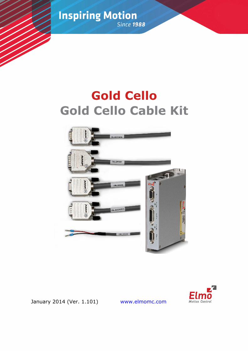
Gold Cello Gold Cello Cable Kit January 2014 (Ver. 1.101) www.elmomc.com
Transcript of Gold Cello Cable Kit
www.elmomc.com
Notice
This guide is delivered subject to the following conditions and restrictions:
• This guide contains proprietary information belonging to Elmo Motion Control Ltd. Such information is supplied solely for the purpose of assisting users of the Gold Cello servo drive in its installation.
• The text and graphics included in this manual are for the purpose of illustration and reference only. The specifications on which they are based are subject to change without notice.
• Information in this document is subject to change without notice.
Document no. MAN-G-CEL-CBLKIT (Ver. 1.101) Copyright 2014
Elmo Motion Control Ltd. All rights reserved.
Catalog Number CBL-GCELKIT
Revision History
Version Date Details
Ver. 1.000 December 2013 Initial release
Ver. 1.100 December 2013 Updated the pinout details on all tables.
Notes added regarding communication cables and CAN Terminator
Ver. 1.101 January 2014 Updated the cable kit catalog number.
Table of Contents MAN-G-CEL-CBLKIT (Ver. 1.101)
www.elmomc.com
3
Chapter 1: Introduction .................................................................................................... 4
1.1. Cable Kit .......................................................................................................................... 4
Chapter 2: Feedback Port A Cable (CBL-DFDBK) ................................................................. 5
Chapter 3: Feedback Port B Cable (CBL-GDCPORTB) .......................................................... 7
Chapter 4: Port C Cable (CBL-GDCPORTC) .......................................................................... 9
Chapter 5: I/O Cable (CBL-GDCI/O) ................................................................................. 11
Chapter 6: VL+ Auxiliary Supply (CBL-CEL24) ................................................................... 13
Chapter 7: CAN Terminator (ACC-TRM-01) When requested specifically .......................... 14
Gold Cello Cable Kit MAN-G-CEL-CBLKIT (Ver. 1.101)
www.elmomc.com
4
Chapter 1: Introduction This document provides the wiring details for the cables used to connect Elmo's Gold Cello servo drive with the end-user application. The servo drive-side pinouts are provided in the Gold Cello Installation Guide.
The cables come in one length: 2 meters (6 ½ feet).
1.1. Cable Kit The catalog number of the Gold Cello cable kit is CBL-GCELKIT.
NOTE:
It should be noted that this kit does not include any communication cables. Please purchase these cables separately.
This cable kit includes the following cables:
ELMO Part Number Function
CBL-DFDBK Feedback Port A
CBL-GDCPORTB Feedback Port B
CBL-GDCPORTC Port C
CBL-GDCI/O I/O cable
CBL-CEL24 VL+ auxiliary supply
In addition, standard cables that are not included in the cable kit are used to connect to the EtherCAT In, EtherCAT Out and Mini-USB B-type connectors. NOTE: The CAN Terminator (ELMO Part Number ACC-TRM-01) must be separately requested when the servo drive is located at the end point of the customer network. For details of the operation of the CAN Terminator please refer to Chapter 7:.

Gold Cello Cable Kit MAN-G-CEL-CBLKIT (Ver. 1.101)
www.elmomc.com
5
Chapter 2: Feedback Port A Cable (CBL-DFDBK) The feedback port A cable is made from a six-pair 24-AWG shielded twisted-pair cable. There is one type of feedback cable, which uses a 15-pin D-Type male connector to connect to the Gold Cello on the servo drive side. The part number (P/N) of this cable is CBL-DFDBK.
The feedback port A cable is open on the motor side so that it can be connected to the motor-feedback connector.
The general pinout of the feedback port A cable is as follows:
Pin No.
Signal Color Twisted & Shielded Wire
Plug
1 HC Green Pair
15-Pin D-Type Male
Connector
10 HB Yellow
3 COMRET White Pair
4 +5V Brown
5 PortA_ENC_A- Orange Pair
6 PortA_ENC_A+ Cyan
7 PortA_ENC_INDEX- Blue Pair
8 PortA_ENC_INDEX+ Red
2 HA Pink Pair
- Reserved Gray
14 PortA_ENC_B- Black Pair
15 PortA_ENC_B+ Purple
* PE - Drain Wire
* - Connector Frame
Pin Positions
15-Pin D-Type Female Connector
15-Pin D-Type Male Connector
Gold Cello Cable Kit MAN-G-CEL-CBLKIT (Ver. 1.101
www.elmomc.com
6
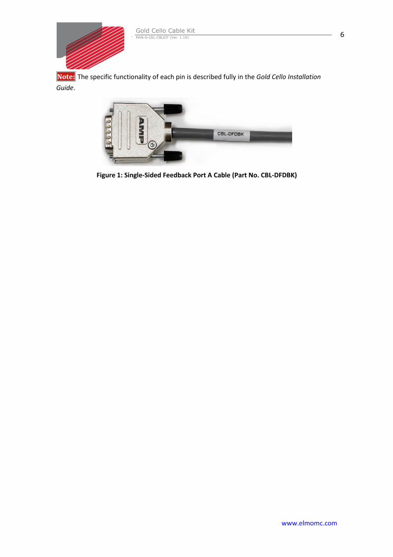
Note: The specific functionality of each pin is described fully in the Gold Cello Installation Guide.
Figure 1: Single-Sided Feedback Port A Cable (Part No. CBL-DFDBK)
Gold Cello Cable Kit MAN-G-CEL-CBLKIT (Ver. 1.101)
www.elmomc.com
7
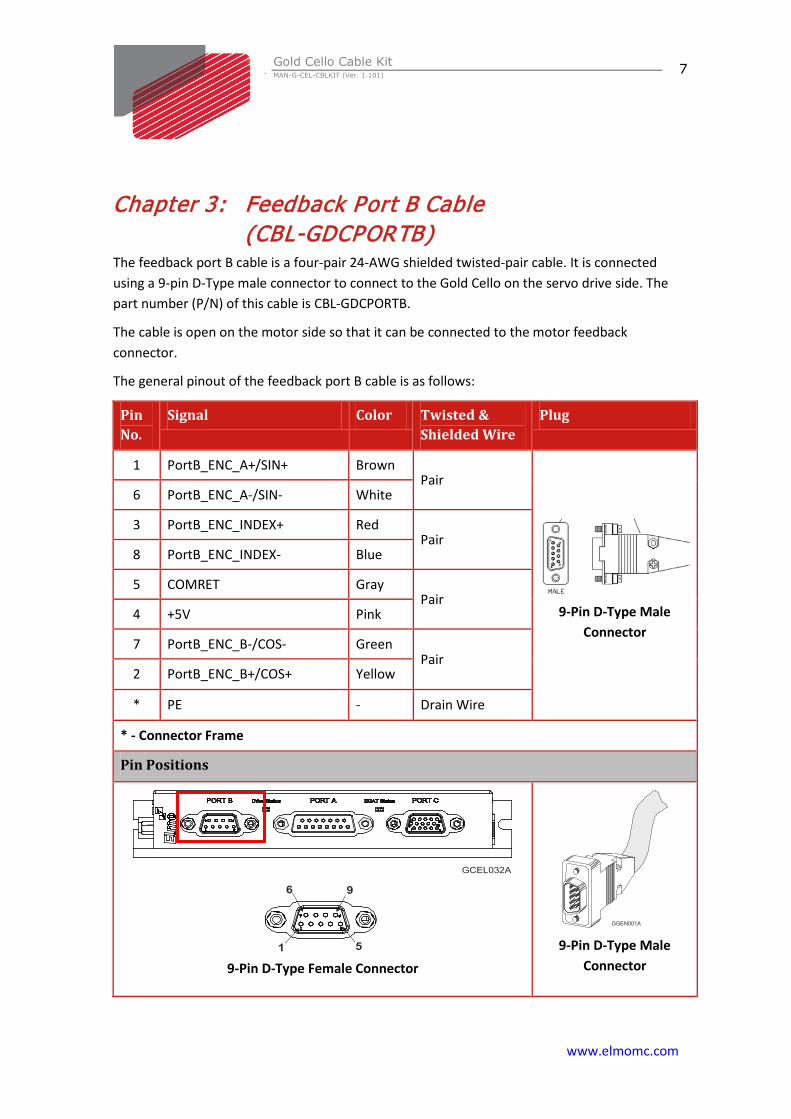
Chapter 3: Feedback Port B Cable (CBL-GDCPORTB)
The feedback port B cable is a four-pair 24-AWG shielded twisted-pair cable. It is connected using a 9-pin D-Type male connector to connect to the Gold Cello on the servo drive side. The part number (P/N) of this cable is CBL-GDCPORTB.
The cable is open on the motor side so that it can be connected to the motor feedback connector.
The general pinout of the feedback port B cable is as follows:
Pin No.
Signal Color Twisted & Shielded Wire
Plug
1 PortB_ENC_A+/SIN+ Brown Pair
9-Pin D-Type Male
Connector
6 PortB_ENC_A-/SIN- White
3 PortB_ENC_INDEX+ Red Pair
8 PortB_ENC_INDEX- Blue
5 COMRET Gray Pair
4 +5V Pink
7 PortB_ENC_B-/COS- Green Pair
2 PortB_ENC_B+/COS+ Yellow
* PE - Drain Wire
* - Connector Frame
Pin Positions
9-Pin D-Type Female Connector
9-Pin D-Type Male
Connector
Gold Cello Cable Kit MAN-G-CEL-CBLKIT (Ver. 1.101
www.elmomc.com
8
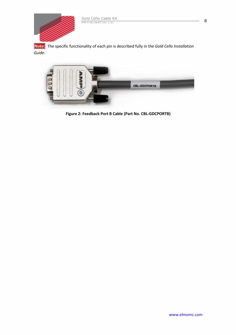
Note: The specific functionality of each pin is described fully in the Gold Cello Installation Guide.
Figure 2: Feedback Port B Cable (Part No. CBL-GDCPORTB)
Gold Cello Cable Kit MAN-G-CEL-CBLKIT (Ver. 1.101)
www.elmomc.com
9
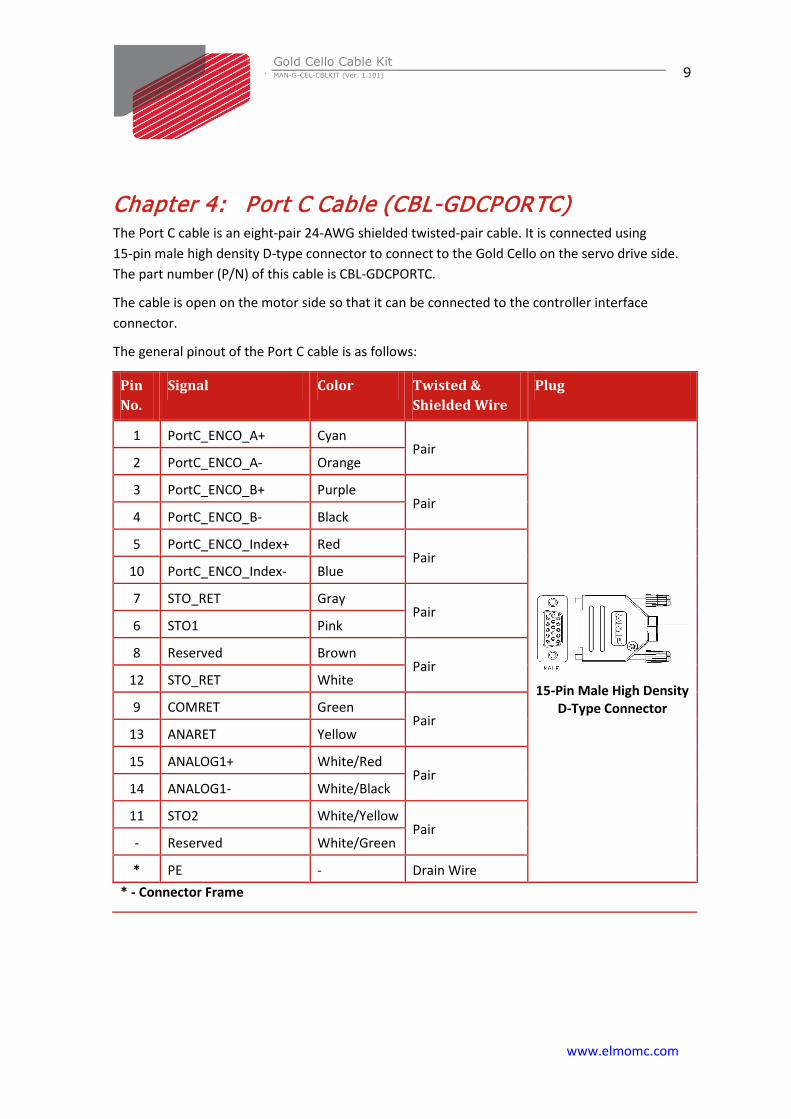
Chapter 4: Port C Cable (CBL-GDCPORTC) The Port C cable is an eight-pair 24-AWG shielded twisted-pair cable. It is connected using 15-pin male high density D-type connector to connect to the Gold Cello on the servo drive side. The part number (P/N) of this cable is CBL-GDCPORTC.
The cable is open on the motor side so that it can be connected to the controller interface connector.
The general pinout of the Port C cable is as follows:
Pin No.
Signal Color Twisted & Shielded Wire
Plug
1 PortC_ENCO_A+ Cyan Pair
15-Pin Male High Density
D-Type Connector
2 PortC_ENCO_A- Orange
3 PortC_ENCO_B+ Purple Pair
4 PortC_ENCO_B- Black
5 PortC_ENCO_Index+ Red Pair
10 PortC_ENCO_Index- Blue
7 STO_RET Gray Pair
6 STO1 Pink
8 Reserved Brown Pair
12 STO_RET White
9 COMRET Green Pair
13 ANARET Yellow
15 ANALOG1+ White/Red Pair
14 ANALOG1- White/Black
11 STO2 White/Yellow Pair
- Reserved White/Green
* PE - Drain Wire * - Connector Frame
Gold Cello Cable Kit MAN-G-CEL-CBLKIT (Ver. 1.101
www.elmomc.com
10
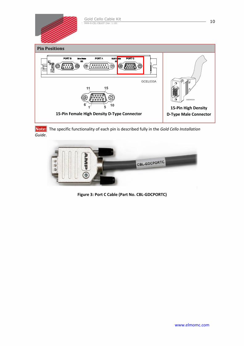
Pin Positions
15-Pin Female High Density D-Type Connector
15-Pin High Density
D-Type Male Connector
Note: The specific functionality of each pin is described fully in the Gold Cello Installation Guide.
Figure 3: Port C Cable (Part No. CBL-GDCPORTC)
Gold Cello Cable Kit MAN-G-CEL-CBLKIT (Ver. 1.101)
www.elmomc.com
11
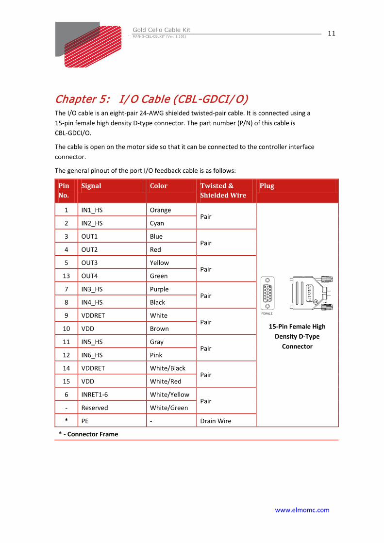
Chapter 5: I/ O Cable (CBL-GDCI/ O) The I/O cable is an eight-pair 24-AWG shielded twisted-pair cable. It is connected using a 15-pin female high density D-type connector. The part number (P/N) of this cable is CBL-GDCI/O.
The cable is open on the motor side so that it can be connected to the controller interface connector.
The general pinout of the port I/O feedback cable is as follows:
Pin No.
Signal Color Twisted & Shielded Wire
Plug
1 IN1_HS Orange Pair
15-Pin Female High
Density D-Type Connector
2 IN2_HS Cyan
3 OUT1 Blue Pair
4 OUT2 Red
5 OUT3 Yellow Pair
13 OUT4 Green
7 IN3_HS Purple Pair
8 IN4_HS Black
9 VDDRET White Pair
10 VDD Brown
11 IN5_HS Gray Pair
12 IN6_HS Pink
14 VDDRET White/Black Pair
15 VDD White/Red
6 INRET1-6 White/Yellow Pair
- Reserved White/Green
* PE - Drain Wire
* - Connector Frame
Gold Cello Cable Kit MAN-G-CEL-CBLKIT (Ver. 1.101
www.elmomc.com
12
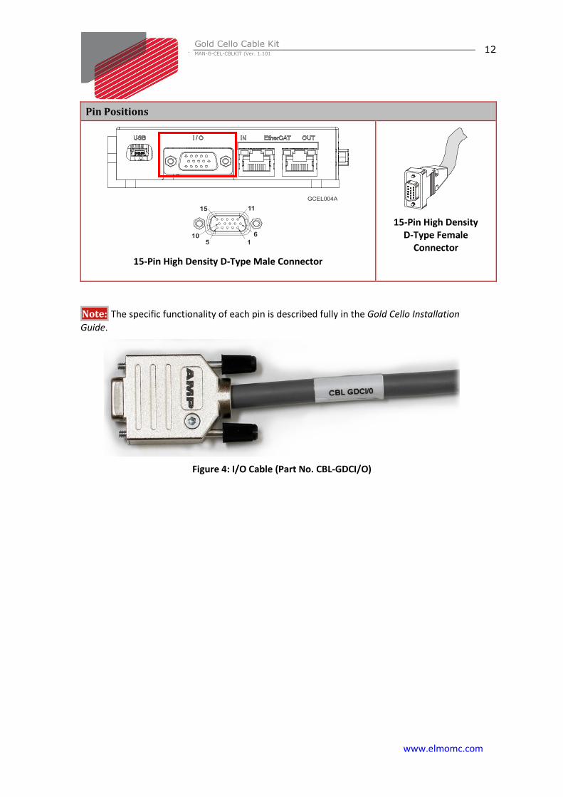
Pin Positions
15-Pin High Density D-Type Male Connector
15-Pin High Density
D-Type Female Connector
Note: The specific functionality of each pin is described fully in the Gold Cello Installation Guide.
Figure 4: I/O Cable (Part No. CBL-GDCI/O)
Gold Cello Cable Kit MAN-G-CEL-CBLKIT (Ver. 1.101)
www.elmomc.com
13
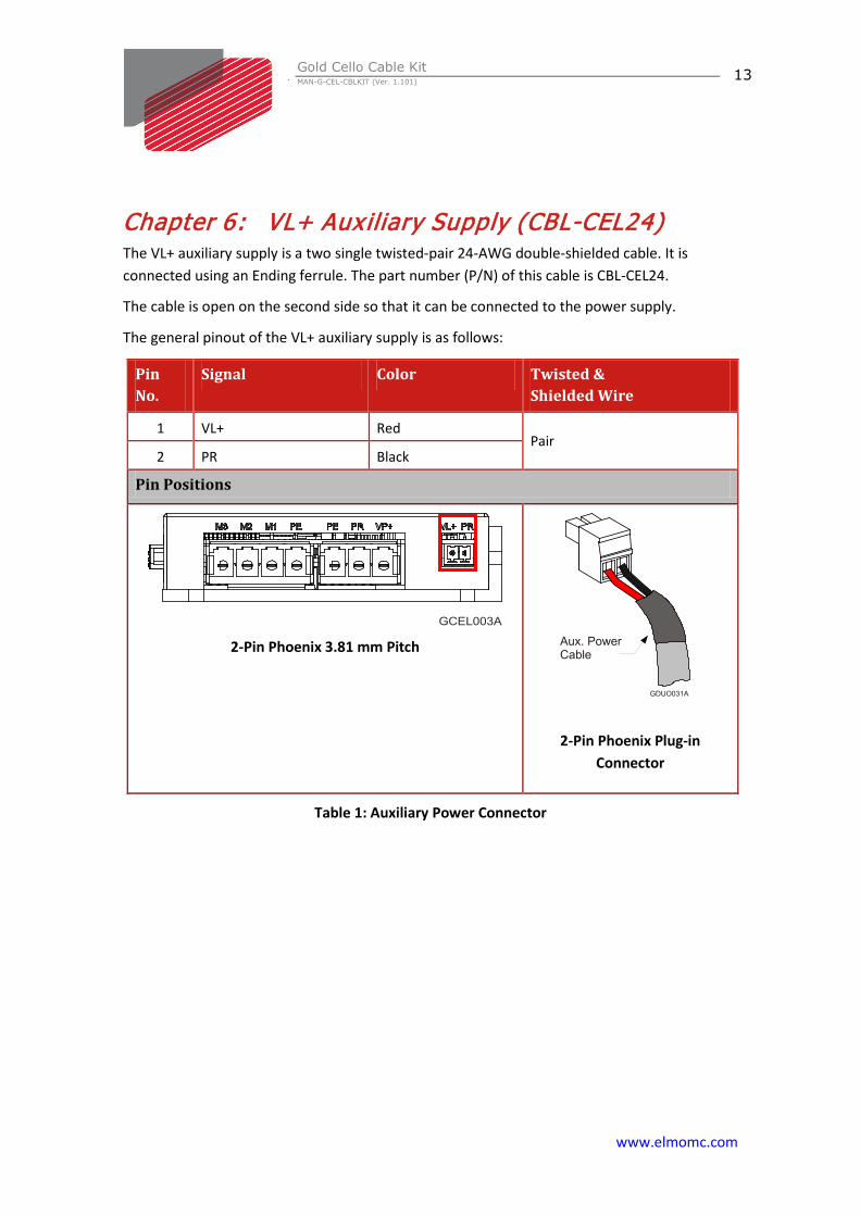
Chapter 6: VL+ Auxiliary Supply (CBL-CEL24) The VL+ auxiliary supply is a two single twisted-pair 24-AWG double-shielded cable. It is connected using an Ending ferrule. The part number (P/N) of this cable is CBL-CEL24.
The cable is open on the second side so that it can be connected to the power supply.
The general pinout of the VL+ auxiliary supply is as follows:
Pin No.
Signal Color Twisted & Shielded Wire
1 VL+ Red Pair
2 PR Black
Pin Positions
2-Pin Phoenix 3.81 mm Pitch
2-Pin Phoenix Plug-in Connector
Table 1: Auxiliary Power Connector
Gold Cello Cable Kit MAN-G-CEL-CBLKIT (Ver. 1.101)
www.elmomc.com
14
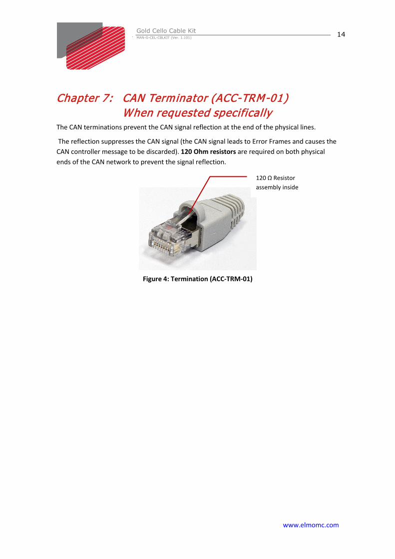
Chapter 7: CAN Terminator (ACC-TRM-01) When requested specifically
The CAN terminations prevent the CAN signal reflection at the end of the physical lines.
The reflection suppresses the CAN signal (the CAN signal leads to Error Frames and causes the CAN controller message to be discarded). 120 Ohm resistors are required on both physical ends of the CAN network to prevent the signal reflection.
Figure 4: Termination (ACC-TRM-01)
120 Ω Resistor assembly inside


![[Cello Plus_PT] Cello Introduction_Eng](https://static.fdocuments.in/doc/165x107/58eebde01a28ab56348b467f/cello-pluspt-cello-introductioneng.jpg)