
Goals of this class - Massachusetts Institute of...
29
© Daniel E Whitney Assembly Workstation Design Issues • Goals of this class – understand workstation elements – look at part feeding and presentation alternatives – design a process and a single station system for it
-
Upload
nguyenxuyen -
Category
Documents
-
view
213 -
download
0
Transcript of Goals of this class - Massachusetts Institute of...

© Daniel E Whitney
Assembly Workstation Design Issues
• Goals of this class– understand workstation elements– look at part feeding and presentation alternatives– design a process and a single station system for it

© Daniel E Whitney
Assembly = Reduction in DoF Uncertainty
0.001
0.01
0.1
1.0
10.0
100 or more STORAGE
BOWLFEEDER
FIXTURE
AMOUNT OFUNCERTAINTYIN PART LOCATION, INCHES
CHAMFERVISIONSENSOR
SPECIALIZEDGRIPPER
FINALASSEMBLYPOINT
PASSIVECOMPLIANCE
PASSIVE/ACTIVE FINEMOTIONDEVICE
PERSON,SHAKER,OR BIN-PICKER PERSON
PERSON
UNSPECIALIZEDGRIPPER
SPECIALIZEDGRIPPER
OEMPARTSCARRIER
SPECIALIZEDGRIPPER
SPECIALIZEDGRIPPER
ORIGINAL MFR
UNSPECIALIZEDGRIPPER
PartLevel
FeatureLevel
ChamferLevel
ClearanceLevel
GeographyLevel
PALLET
BOWLTRACKEXIT

© Daniel E Whitney
What Happens in a Workstation• An incomplete assembly arrives (or several at once)• Parts to be assembled arrive
– as single parts– as a subassembly
• Parts may have to be separated, oriented, given a final check
• Parts are joined to the assembly• Assembly correctness is checked• Documentation may have to be filled out• The assembly is passed on to the next station
© Daniel E Whitney
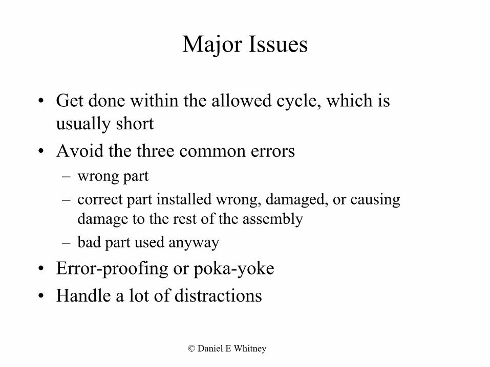
Major Issues
• Get done within the allowed cycle, which is usually short
• Avoid the three common errors– wrong part– correct part installed wrong, damaged, or causing
damage to the rest of the assembly– bad part used anyway
• Error-proofing or poka-yoke• Handle a lot of distractions

© Daniel E Whitney
Cycle Time
• Varies from milliseconds for cigarettes to days for aircraft
• Components– work in/out– move to get tool– move to get part– move to insertion point– insert– move to get new tool
• Each move includes accel-steady speed-decel-creep
timeRAMPUP TOFULLSPEED
RUN ATFULL SPEED
RAMPDOWN
CREEP
SPEEDDISTANCE
22 40 38
14 68 18
60% OF THE TIME IS SPENT COVERING ONLY 32% OF THE DISTANCE
% TIME
% DISTANCECOVERED

© Daniel E Whitney
http://www.silma.com
Simulation Softw
areCourtesy of Applied Computing & Engineering (c) - http://www.acel.co.uk
© Daniel E Whitney
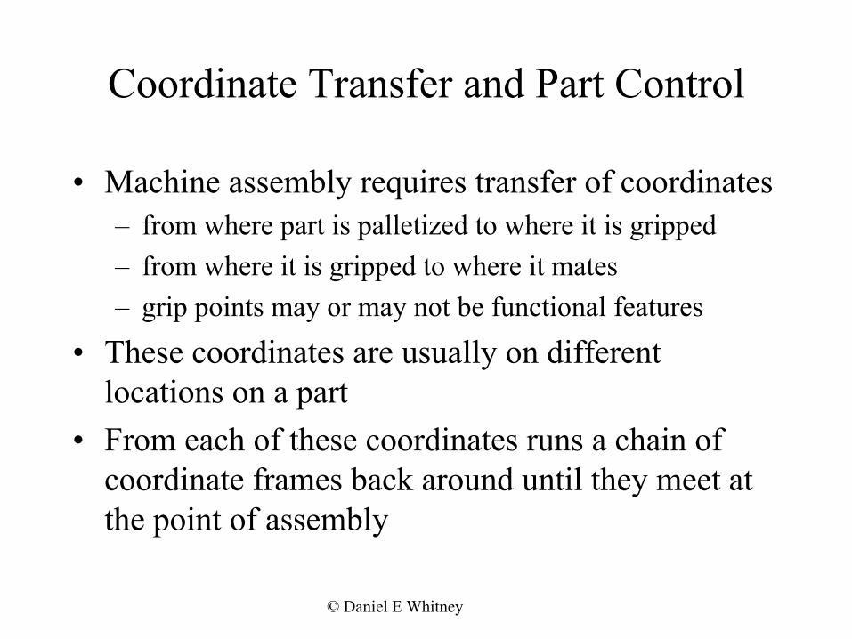
Coordinate Transfer and Part Control
• Machine assembly requires transfer of coordinates– from where part is palletized to where it is gripped– from where it is gripped to where it mates– grip points may or may not be functional features
• These coordinates are usually on different locations on a part
• From each of these coordinates runs a chain of coordinate frames back around until they meet at the point of assembly

© Daniel E Whitney
Assem
blability
AB
C
D
E
F & A
Σ
G
SOME OF THE MANY SOURCES OF ERROR THAT MUST BECONTROLLED IN ORDER TOACHIEVE SUCCESSFUL ASSEMBLY
A. PART CONSTRUCTIONB. PART JIGGINGC. JIG LOCATIOND. ROBOT ACCURACY AND CALIBRATIONE. TOOL SOCKETF. PART GRIPG. OFFLINE MODEL
2 = A + B + C + D + E + F + G2 222222
Σ
© Daniel E Whitney
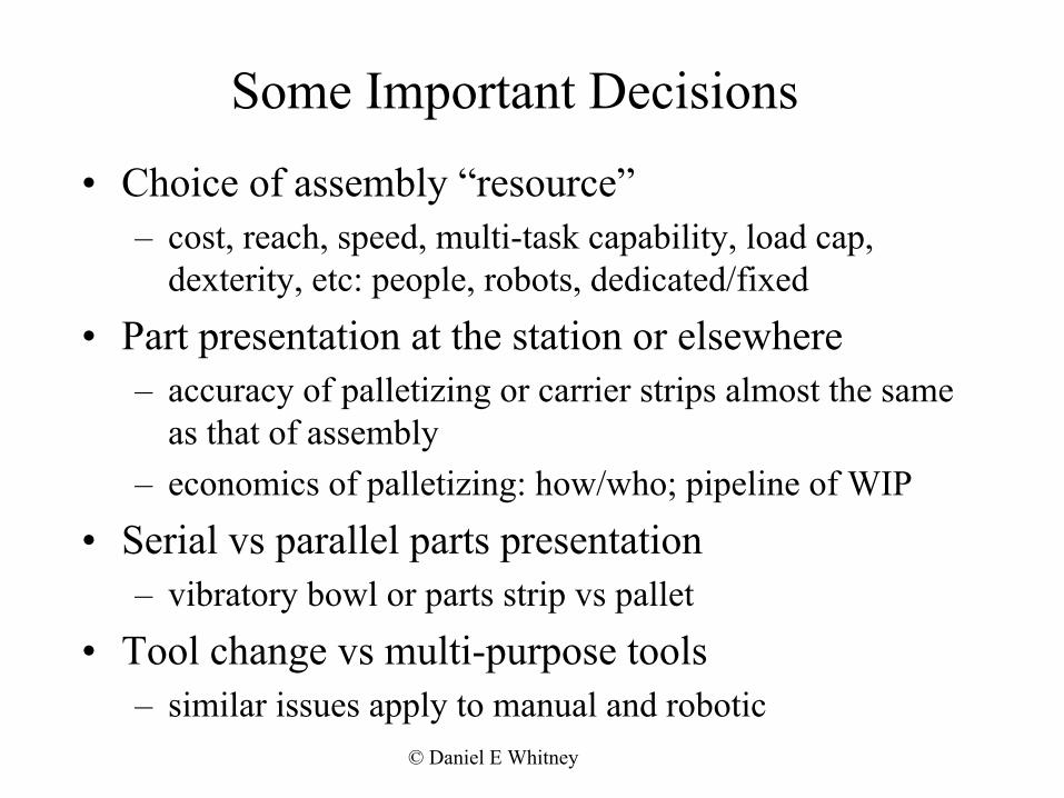
Some Important Decisions
• Choice of assembly “resource”– cost, reach, speed, multi-task capability, load cap,
dexterity, etc: people, robots, dedicated/fixed
• Part presentation at the station or elsewhere– accuracy of palletizing or carrier strips almost the same
as that of assembly– economics of palletizing: how/who; pipeline of WIP
• Serial vs parallel parts presentation – vibratory bowl or parts strip vs pallet
• Tool change vs multi-purpose tools– similar issues apply to manual and robotic

© Daniel E Whitney
Other Important Decisions
• Allocation of degrees of freedom– all in one place– shared between two, as in 4 DOF robot and 2 DOF
workholder
• Combinations of fab and part arrangement with assembly– creates parts or subassemblies on the spot– examples: pre-assembly of valve keepers, spring
winding, lubrication, sorting

© Daniel E Whitney
Valve Keepers
SelectedSolidLifter
Cam
Cylinder Head
Valve

© Daniel E Whitney
Workstation Layout• Part presentation
– Automatic feeders– Chutes loaded from opposite side– Bulk parts vs kits
• Station layout to provide– Parts and tools within easy reach– Things laid out in process sequence– Instructions - paper, video for each version– Instructions - what version is this– Documentation - tests performed, parts installed
• Line layout to provide– Space for materials at lineside– Space for transporters

© Daniel E Whitney
Sony APOS
• Offline shakers fill pallets (~ 10” x 12”)• Part jams, if any, occur off line and do not stop the
assembly system• Rather complex parts can be presented automatically• Pallets occupy considerable space at the workstation• The robot spends a lot of time slewing over to the
pallet to get a part• So you trade time for space: do you win?

© Daniel E Whitney
Sony APOS - Palletizer
TRACK FORPALLETS TOARRIVE AND LEAVE
PALLET ONSHAKER
PARTS HOPPERS
MECHANISM FOR RETURNINGEXCESS PARTS TO HOPPERS

© Daniel E Whitney
Sony APOS - Assembly Station
NEXTDONE WORKINGPALLET
1
2
3
4
5
ROBOT WORKENVELOPE
CONVEYOR
...........
...........
......
TO PALLETFILLINGEQUIPMENT
PARTSPALLETS

© Daniel E Whitney
Other Architectures• Escort parts and tools (early Sony FX-1)• Flexibility based on station lockout
– one simple station per part or version thereof– assembly passes through unneeded stations– lots of floor space
• Roving robot (Hitachi, 1980)– carries assembly in its “lap” – visits stations that feed parts and hold special tools
• Roving robot teams (Denso, 2000)– Robots carry tools, assemblies ride conveyor, parts delivered at
stations– Robots can be added or removed from system to adjust capacity– Robots can share work at highly loaded stations
• Parts made in or fastened to carrier strips - separates part prep from part feeding for higher feeding reliability

© Daniel E Whitney
Pallet Arrangement for Large Parts
ASSEMBLYPALLET
UNIQUEPARTS FORONE ASSEMBLY
BULK PARTSFOR SEVERALASSEMBLIES

© Daniel E Whitney
Spot
Line
Area
Cube
Network
FMS-0 FMS-1 FMS-2 FMS-3
Improvement of Denso Production System
Mechanical Spot Automation
TransferLine
RobotCell
MobileRobot
(Slide from Denso)
See “Nippondenso: a case study of strategic product design”. Courtesy of Denso Wave, Inc., Japan.Used with permission.

© Daniel E Whitney
Cartesian Robot
Workpiece Circulation System
Stocker
End Effector
High Rigidity Robot
Conveyor
Small Volume
4 times circulation
twice circulation
Medium Volume
No Circulation
Large Volume
FMS-3(Fluctuation Adaptive System)
-Change the number of assembly cellsto adapt to the fluctuation of the production volume
Assembly Cell
(Slide from Denso)
Courtesy of Denso Wave, Inc., Japan.Used with permission.

© Daniel E Whitney
Starter Assembly Automation Line
End Frame
Armature
Magnet Switch
Clutch
Yoke
Housing
Starter(Slide from Denso)
Courtesy of Denso Wave, Inc., Japan. Used with permission.

© Daniel E Whitney
Increasing and Decreasing Mobile Robots
Higher Production Volume : 3 mobile robots
- Increase/Decrease the number of RobotsAccording to Production Volume
LowerProduction Volume : 2 mobile robots
(Slide from Denso)
Courtesy of Denso Wave, Inc., Japan.Used with permission.

© Daniel E Whitney
Making Stacks - Method 1
12
aa a
a aa
b bb
b b b
a/bstacks
3
need astack every 25 sec
individual a'sand b's arriving
camera neededto aid gripping
ALTERNATIVE 1: ROBOT GRIPS 1 a AND 1 b
PROGRAM IS 1, 2, 3, 1...EACH SUBMOVE TAKES T SEC:1 TO 2, 2 TO 3, 3 TO 1, 5 TIMES.TIME FOR A STACK OF 5 a's, 5 b's = 15*T SECSO T MUST BE 25/15 = 1.67 SEC.
ALTERNATIVE 2: ROBOT CAN GRIP UP TO 5 a's AND 5 b's
PROGRAM IS (3 TO 2), {(2 TO 1) 5 TIMES, (1 TO 2) 4 TIMES INTERLEAVED}PLUS (1 TO 3).TIME FOR A STACK OF 10 = 11*T SEC.SO T MUST BE 25/11 = 2.27 SEC.
SINCE T FOR A ROBOT OF THIS SIZE IS TYPICALLY 5 SEC,ALT 1 WOULD REQUIRE 4 SUCH STATIONS, WHILE ALT 2WOULD REQUIRE 3.
© Daniel E Whitney
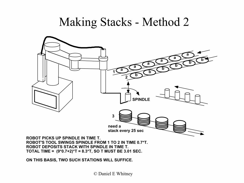
Making Stacks - Method 2
12
aa
aa a
a
bb
bb
b b
SPINDLE
3
need astack every 25 sec
ROBOT PICKS UP SPINDLE IN TIME T.ROBOT'S TOOL SWINGS SPINDLE FROM 1 TO 2 IN TIME 0.7*T.ROBOT DEPOSITS STACK WITH SPINDLE IN TIME T.TOTAL TIME = (9*0.7+2)*T = 8.3*T, SO T MUST BE 3.01 SEC.
ON THIS BASIS, TWO SUCH STATIONS WILL SUFFICE.

© Daniel E Whitney
Making Stacks - Method 3
3
need astack every 25 sec
12
aa
aa a
bb
bb
b
ab
FLIPPER
SLIPPERS
FLIPPER FLIPS EVERY 2 SEC. SLIPPERS SLIDEA DISK ONTO EACH SPINDLE ON THE FLIPPER.TWO COMPLETE STACKS ARE DONE IN 10 SEC.ROBOT TRANSFERS THEM TO CONVEYOR IN 5 SEC.NET TIME PER STACK = 7.5 SEC
IF THERE ARE N FLIPPER-SLIPPERS, THE ROBOT SERVESEACH ONE EVERY 5N SEC. SO EACH ONE PRODUCES ASTACK EVERY 2.5N SEC. IF EACH MAKES A STYLE THAT ISNEEDED ONCE EACH 25 SEC, THEN A ROBOT CAN SERVE 10FLIPPER-SLIPPERS.

© Daniel E Whitney
AMP Ignitor
ALUMINUM TOPWITH HOLE
PLASTICWINDOW
FUSE WIRE
PLASTICHOUSING
STEEL CAP
WASHER
STEEL CAP
FIBERWASHER
STEEL BODY
POWDER
(A)
ACCESS HOLEFOR FIRINGIGNITOR
STEEL CAP
WASHER
(B)
(C)
STEEL CAP
WASHER

© Daniel E Whitney
Manual A
ssembly Sequence
STEEL CAP
WASHER
STEEL CAP
WASHER
PLACEWINDOW
INSERTAND BENDWIRE
PRESS HOUSINGAND WIRE INTOTOP
POUR INPOWDER
PRESS ONCAP
BEND WIRE PLACE WASHER
PRESS SUBASSEMBLYINTO BODYMANUAL ASSEMBLY SEQUENCE
© Daniel E Whitney
Alternate Process
STEEL CAP
WASHER
STEEL CAP
WASHER
PLACE WASHER
PRESS SUBASSEMBLYINTO BODY
INSERTAND BENDWIRE
PRESS HOUSINGAND WIRE INTOCAP
POUR INPOWDER
PLACE WINDOW(A PRESS FIT)
PRESS ONTOP WITHWINDOW

© Daniel E Whitney
Alternate Process O
ne-handed
X
HOUSINGGRIPPER
WIREPINCHERS
PLACE HOUSINGOVER PINCHERS
FEED WIRETHROUGH
PINCH WIRE ROTATE CLOCKWISE90 DEGREES
PRESS IN CAP CUT WIRE ROTATE COUNTER-CLOCKWISE 90 DEGREES
CARRY TO POWDERFILL STATION
CARRY TOTOP PRESS
STATION
CARRY TO BODYPRESS STATION

© Daniel E Whitney
Single Station System
HousingFeeder
Wire Feed and CutStation
Cap Feedand PressStation
WindowFeeder
TopFeeder
Press windowinto topPress topinto housing
PowderFill Station
Body FeederWasher Feedand Drop intoBody
Press sub-assy intobody
TestOK
NotOK


![[XLS]tamilchess.comtamilchess.com/wp-content/uploads/2015/12/TN-Regn-List... · Web view1 3/14/2009 3/24/2009 35817 2 5016100 7/18/1960 35795 3 5069084 1/20/1962 35795 4 45016143](https://static.fdocuments.in/doc/165x107/5af2d6817f8b9a8b4c90af4e/xls-view1-3142009-3242009-35817-2-5016100-7181960-35795-3-5069084-1201962.jpg)
