Goals and Status of MICE The International Muon Ionization Cooling Experiment
31
Goals and Status of MICE Goals and Status of MICE The International Muon Ionization Cooling The International Muon Ionization Cooling Experiment Experiment J.S. Graulich
-
Upload
valentine-miles -
Category
Documents
-
view
29 -
download
0
description
Goals and Status of MICE The International Muon Ionization Cooling Experiment. Plan. Motivations Muon Cooling MICE Design and Challenges MICE’s current status Beam Line Detectors Simulation and Analysis Software Preparing for the future Conclusion. Motivations: Neutrino Physics. - PowerPoint PPT Presentation
Transcript of Goals and Status of MICE The International Muon Ionization Cooling Experiment

Goals and Status of MICEGoals and Status of MICE The International Muon Ionization Cooling The International Muon Ionization Cooling
ExperimentExperiment
J.S. Graulich
PlanPlan
MotivationsMotivations Muon CoolingMuon Cooling MICE Design and ChallengesMICE Design and Challenges MICE’s current statusMICE’s current status
Beam Line Detectors Simulation and Analysis Software
Preparing for the futurePreparing for the future ConclusionConclusion
WIN 11 J.S. Graulich Slide 2

WIN 11 J.S. Graulich Slide 3
Motivations:Motivations:Neutrino PhysicsNeutrino Physics
Fundamental questions raised by neutrinosFundamental questions raised by neutrinos Do they conserve the lepton number? Are they their own anti-particle ? Do they have Majorana masses ? Do their oscillations violate CP ? Why masses are so small ?
A strong need for precision measurementsA strong need for precision measurements Mixing angles, Mass differences, Mass Hierarchy, CP
Requires a new generation of facilitiesRequires a new generation of facilities Among the options: Super beam, Beta beam and Neutrino
factory Neutrino factory
is not the simplestoffers the best potential: performance and
flexibility
See Boris Kayser’s talk:“Seeking CP violation in neutrino oscillation is now a worldwide goal.”

Motivation:Motivation:The Neutrino FactoryThe Neutrino Factory
Slide 4
• High energy & intensity • Very well defined beam content ( , e) or ( , e)
• Start to End Simulation exists IDS ! see A. Cervera• 3 essential R&D needed - High power Target - Muon Cooling - FFAGs
The neutrino factory is the ultimate tool for precise neutrino studies
Sensitivity to CP
CERN Scientific Policy Committee, March 2010

Muon CoolingMuon Cooling
Large divergence >< efficient Large divergence >< efficient accelerationacceleration
Beam Cooling = Emittance reductionBeam Cooling = Emittance reduction What is emittance ? ≠ divergenceWhat is emittance ? ≠ divergence
In the 2D case (oversimplified) a beam is defined by a set of xi(z)
x’ = dx/dz = Px/P
WIN 11 J.S. Graulich Slide 5
2''
'2
)(xxx
xxxzV
)(2'
2'
2 VDetxxxx
In the absence of dissipative forces, is conserved !

Ionization CoolingIonization Cooling How to reduce emittance ? -> How to reduce emittance ? ->
FrictionsFrictions Standard techniques don’t work for Standard techniques don’t work for
muonsmuons They need >> 2.2 s
Two stepsTwo steps Energy loss by ionization (dE/dX) Forward re-acceleration by RF cavities
WIN 11 J.S. Graulich Slide 6
Cooling is achieved only for low Z material ! Mult. Scat. < dE/dx -> Liquid Hydrogen

Cooling CellCooling Cell
Easy in principle…Easy in principle… In practice, the emittance is so large In practice, the emittance is so large
thatthat Need to contain the beam Not single pass -> iterations
Technical ChallengesTechnical Challenges An extended liquid Hydrogen cryogenic system High gradient RF cavities in strong magnetic
field Large number of Superconducting coils strongly
coupled to each other
That’s why we need R&D -> MICEThat’s why we need R&D -> MICE
WIN 11 J.S. Graulich Slide 7

MICEMICE
WIN 11 J.S. Graulich Slide 8
Muon Ionisation Cooling ExperimentMuon Ionisation Cooling Experiment Design, build and operate a realistic section of
cooling channel Measure its performances (in different modes)

MICE Step By StepMICE Step By Step
Commission beamline & detectors
Precisely measureincoming emittance& compare trackers
Precisely measuremuon cooling
Test sustainablecooling
Ultimate MICEgoal: operate fullcooling channel
Slide 9J.S. Graulich
2012
Complete !(This talk)
WIN 11 J.S. Graulich Slide 10
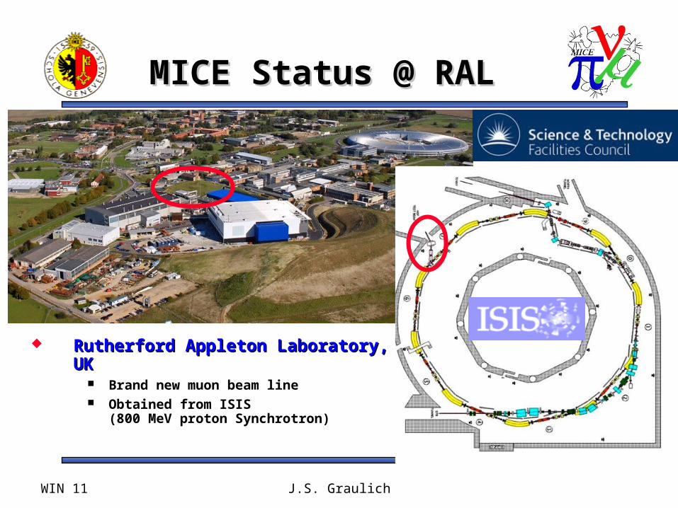
MICE Status @ RALMICE Status @ RAL
Rutherford Appleton Laboratory, Rutherford Appleton Laboratory, UKUK
Brand new muon beam line Obtained from ISIS
(800 MeV proton Synchrotron)

WIN 11 J.S. Graulich Slide 11
MICE Beam LineMICE Beam Line
Design Specifications:Design Specifications:- ~ ~ 1 Spill / 2 seconds- ~ ~ 3 ms Spill duration
- 100 muons / Spill - Muon momentum between 140 to 240 MeV/c- pD2 = pD1/2 (backward muons)
D1D2
Q1-Q3
Q4-Q6 Q7-Q9

The Beamline is The Beamline is OperationalOperational
WIN 11 J.S. Graulich Slide 12
Pion Decay Solenoid (during installation)
Q7-Q9
Q4-Q6
D2
Downstream Muon Beam Line
Mice Target System in ISIS
Upstream Pion Beam Line
Q1-Q3D1

The Target is pulsingThe Target is pulsing
Stator
Positionreading
Bearing
Ti Target
WaterCooling
MICE Ti Target inside the ISIS beam pipe
Critical active partCritical active part Parasitic mode: no Parasitic mode: no
perturbation to ISIS Users perturbation to ISIS Users 80 g acceleration !80 g acceleration ! Magnetic “gun” Magnetic “gun” 570 000 dips570 000 dips
@ 0.4 Hz@ 0.4 Hz

Slide 14
Instrumentation for Instrumentation for Step 1Step 1
All detectors for Step 1 are operational
TOF0 after the 2nd triplet
TOF1 after the 3rd triplet
TOF2 at the very end (will move)Luminosity Monitors
3 Time of FlightStations
Calorimeter
2 Cherenkovs
DownstreamMonitor (GVA1)
Beam ProfileMonitors

Detector RatesDetector Rates
WIN 11 J.S. Graulich Slide 15
Detector Rates scale linearly with Beam Loss

Lyon, Octobre 2009 Slide 16
All TOF installed All TOF installed
Two crossed layers of scintillator slabs, Two crossed layers of scintillator slabs, 1” thick1” thick
Fast PMTs on both sidesFast PMTs on both sides Muon/pion/electron PIDMuon/pion/electron PID Measure the RF phase when muon Measure the RF phase when muon
arrivesarrives Magnetic shielding is crucial for TOF1/2Magnetic shielding is crucial for TOF1/2
TOF1 installed at RAL
TOF Scintillator

TOF ResolutionTOF Resolution
WIN 11 J.S. Graulich Slide 17

WIN 11 J.S. Graulich
Particle Particle IdentificationIdentification
Very precise Time of Flight measurement between TOF0 and TOF1
Allows separation betweenElectrons / muons / pions /
For all momenta up to 280 Mev/c

WIN 11 J.S. Graulich
Selecting Backward Selecting Backward MuonsMuons
We want a muon beam !
We tune the second dipole (D2) to select muons going backward (in C.M. frame) w.r.t. to the original pions’ direction
P ≈ P / 2

Pure muon BeamPure muon Beam
WIN 11 J.S. Graulich 20
Selecting backward muons
Pions are not transported
Electrons are depleted
MICE has a muon beam !~ 30 muons/spill/ V.ms

Lyon, Octobre 2009 Jean-Sébastien Graulich Slide 21
Simulation and Simulation and Analysis Software: Analysis Software:
G4MICEG4MICE
Based on GEANT 4 for the simulationBased on GEANT 4 for the simulation A deliverable by itself
Also used for beam transport optimizationAlso used for beam transport optimization In competition with G4Beamline
Reconstruction of events from both simulation and Reconstruction of events from both simulation and datadata
Calculate elaborated quantity like In particular: momentum
G4BeamLineTransport
G4MiceSimulation and Analysis

WIN 11 J.S. Graulich Slide 22

Q789 = -30%
Phase Space and Momentum Reconstruction: Q789 scan runsPhase Space and Momentum Reconstruction: Q789 scan runs
m. apollonio
Simulation
Data

Phase Space and Momentum Reconstruction: Q789 scan runsPhase Space and Momentum Reconstruction: Q789 scan runs
m. apollonio
Q789 = -20%
Simulation
Data

Phase Space and Momentum Reconstruction: Q789 scan runsPhase Space and Momentum Reconstruction: Q789 scan runs
m. apollonio
Q789 = -10%
Simulation
Data
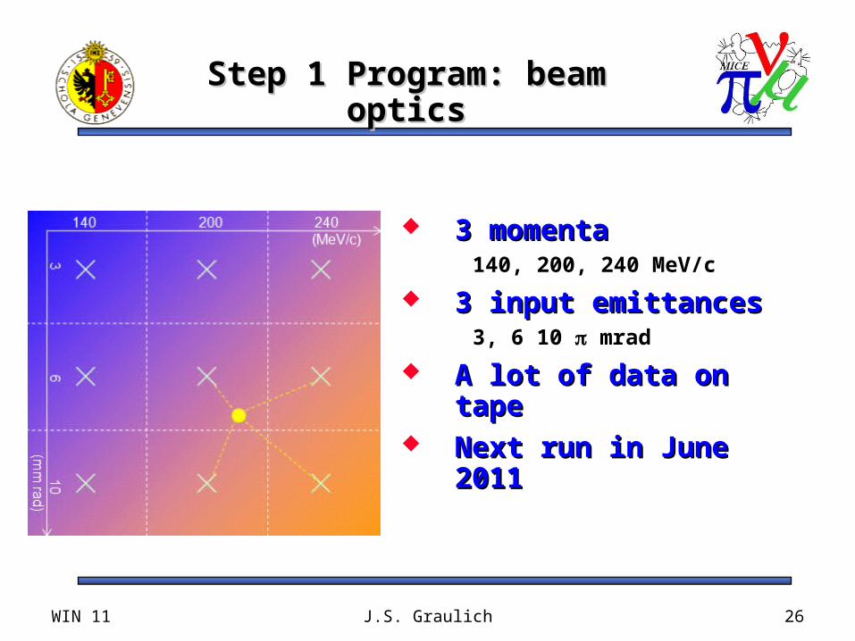
Step 1 Program: beam Step 1 Program: beam opticsoptics
3 momenta3 momenta140, 200, 240 MeV/c
3 input emittances3 input emittances3, 6 10 mrad
A lot of data on A lot of data on tapetape
Next run in June Next run in June 20112011
WIN 11 J.S. Graulich 26

Slide 27
Next Step: Next Step: SpectrometerSpectrometer
Construction problems with the superconducting solenoids
Tracker Ready, tested with cosmics, meet resolution specs
Installation scheduled for 2012

Lyon, Octobre 2009 Jean-Sébastien Graulich Slide 28
Absorbers - FCAbsorbers - FC
Each Absorber contains 20 L of HydrogenEach Absorber contains 20 L of Hydrogen Produced at KEK, JapanProduced at KEK, Japan Thin Aluminum widows, all doubled for Thin Aluminum widows, all doubled for
safetysafety The module integrates the absorber with The module integrates the absorber with
the superconduction focus coil in the superconduction focus coil in production at Teslaproduction at Tesla
Integration to Step IV in 2012Integration to Step IV in 20121st absorber complete at Mirapro

Lyon, Octobre 2009 Jean-Sébastien Graulich Slide 29
RFCC ModuleRFCC Module Each module contains 4 RF Each module contains 4 RF
cavities and a superconducting cavities and a superconducting coupling coilcoupling coil
Water cooled copper cavities, 201 Water cooled copper cavities, 201 MHzMHz
Each module compensates for 11-Each module compensates for 11-12 MeV energy loss in the 12 MeV energy loss in the absorbersabsorbers
High Gradient (8 MV/m) in strong High Gradient (8 MV/m) in strong magnetic field (~4 Tesla)magnetic field (~4 Tesla)
Manufacturing in progressManufacturing in progress Expected for 2013Expected for 2013

SummarySummary
The Neutrino factory is the best tool for future The Neutrino factory is the best tool for future precise neutrino studiesprecise neutrino studies
MICE is exploring muon ionization cooling which MICE is exploring muon ionization cooling which is a key R&D toward the NFis a key R&D toward the NF
MICE has completed its first step at RAL, UKMICE has completed its first step at RAL, UK The muon beam and the detectors have been The muon beam and the detectors have been
successfully commissionedsuccessfully commissioned A particle by particle analysis has already been A particle by particle analysis has already been
used to measure the beam emittance, using used to measure the beam emittance, using TOFsTOFs
The spectrometers and the first absorber will be The spectrometers and the first absorber will be installed in 2012installed in 2012
MICE could be completed by 2013MICE could be completed by 2013
WIN 11 J.S. Graulich Slide 30

WIN 11 J.S. Graulich Slide 31