Goal of accreditation ACR CT Accreditation Program Image ... · ACR CT Accreditation Program Image...
23
ACR CT Accreditation Program Image Quality Phantom and Dose Measurements Tom Payne PhD 1 Cynthia H. McCollough PhD 2 1. Medical Physics, Abbott Northwestern Hosp., Mpls, MN 2. Department of Radiology, Mayo Clinic, Rochester, MN Goal of accreditation Increase quality Increase quality Timeline • Program approved by ACR Council in 1997 • Robert Zeman, M.D. - Chairperson • July 1998 first meeting • Lots of work!!! • Program Piloted summer 2001 • Program active March 2002, over 100 applications requested in 1st month • Required for reimbursement by some insurers in 2004 Physics Subcommittee • Cynthia McCollough, Ph.D., Chair • Tom Payne, Ph.D. • Mike McNitt-Gray, Ph.D. • Tom Ruckdeschel, M.S. • Jim Brink, M.D. • ACR: Pam Wilcox, Penny Butler, Krista Bush, Chris Riha
-
Upload
truongthuy -
Category
Documents
-
view
231 -
download
0
Transcript of Goal of accreditation ACR CT Accreditation Program Image ... · ACR CT Accreditation Program Image...
ACR CT Accreditation Program Image Quality Phantomand Dose Measurements
Tom Payne PhD 1
Cynthia H. McCollough PhD 2
1. Medical Physics, Abbott Northwestern Hosp., Mpls, MN2. Department of Radiology, Mayo Clinic, Rochester, MN
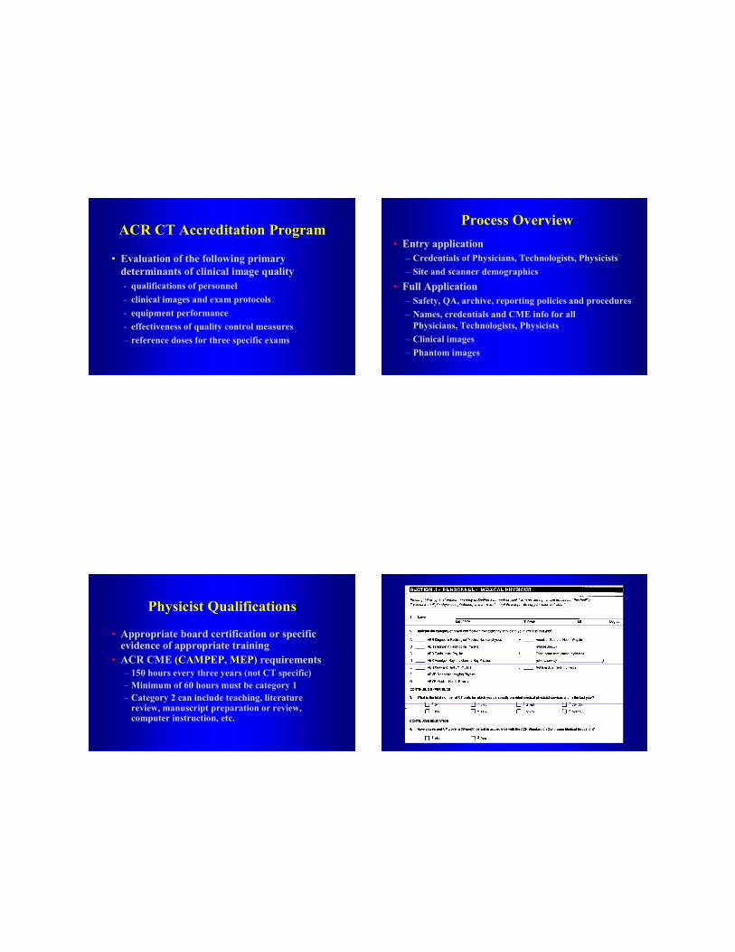
Goal of accreditation
Increase qualityIncrease quality
Timeline• Program approved by ACR Council in 1997• Robert Zeman, M.D. - Chairperson• July 1998 first meeting• Lots of work!!!• Program Piloted summer 2001• Program active March 2002,
over 100 applications requested in 1st month• Required for reimbursement by some insurers
in 2004
Physics Subcommittee
• Cynthia McCollough, Ph.D., Chair• Tom Payne, Ph.D.• Mike McNitt-Gray, Ph.D.• Tom Ruckdeschel, M.S.• Jim Brink, M.D.• ACR: Pam Wilcox, Penny Butler,
Krista Bush, Chris Riha
ACR CT Accreditation Program
• Evaluation of the following primary determinants of clinical image quality- qualifications of personnel- clinical images and exam protocols- equipment performance- effectiveness of quality control measures– reference doses for three specific exams
Process Overview• Entry application
– Credentials of Physicians, Technologists, Physicists– Site and scanner demographics
• Full Application– Safety, QA, archive, reporting policies and procedures– Names, credentials and CME info for all
Physicians, Technologists, Physicists– Clinical images– Phantom images
Physicist Qualifications
• Appropriate board certification or specific evidence of appropriate training
• ACR CME (CAMPEP, MEP) requirements– 150 hours every three years (not CT specific)– Minimum of 60 hours must be category 1– Category 2 can include teaching, literature
review, manuscript preparation or review, computer instruction, etc.
Physicist Qualifications (cont.)
• Physicist may have assistance in data collection– Properly trained individuals approved by the CMP– CMP is responsible for all data– Must be present during initial and annual surveys– Must review, interpret and approve all data– Must provide a signed report of conclusions
Physicist Responsibilities
• Physicist should be available for dosimetry consultations in a reasonable time
• Must establish and supervise QC program– What tests, done by whom, how often– Designate an on-site RT responsible for
conducting routine QC• Initial acceptance testing and annual survey
– Tests should be consistent with ACR Standard for CT Performance Evaluation
Annual Performance Evaluation• Alignment light accuracy• Alignment of table to gantry• Table/gantry tilt• Slice localization from localization image (SPR) • Table incrementation accuracy• Slice thickness• Image quality
– High contrast (spatial) resolution– Low contrast resolution– Image uniformity– Noise– Artifact evaluation
• CT number accuracy and constancy
Annual Performance Evaluation• Display devices
– Video display– Hard-copy display
• Dosimetry− Computed Tomography dosimetry index (CTDI)− Patient radiation dose for representative examinations
• Safety evaluation– Visual inspection– Audible/visual signals– Posting requirements– Scattered radiation measurements
• Other tests as required by state and/or local regulations
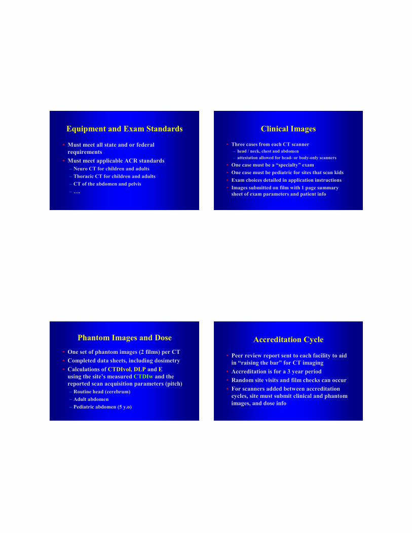
Equipment and Exam Standards
• Must meet all state and or federal requirements
• Must meet applicable ACR standards– Neuro CT for children and adults– Thoracic CT for children and adults– CT of the abdomen and pelvis– ….
Clinical Images
• Three cases from each CT scanner– head / neck, chest and abdomen– attestation allowed for head- or body-only scanners
• One case must be a “specialty” exam• One case must be pediatric for sites that scan kids• Exam choices detailed in application instructions• Images submitted on film with 1 page summary
sheet of exam parameters and patient info
Phantom Images and Dose• One set of phantom images (2 films) per CT• Completed data sheets, including dosimetry• Calculations of CTDIvol, DLP and E
using the site’s measured CTDIw and the reported scan acquisition parameters (pitch)– Routine head (cerebrum)– Adult abdomen– Pediatric abdomen (5 y.o)
Accreditation Cycle
• Peer review report sent to each facility to aid in “raising the bar” for CT imaging
• Accreditation is for a 3 year period• Random site visits and film checks can occur• For scanners added between accreditation
cycles, site must submit clinical and phantom images, and dose info
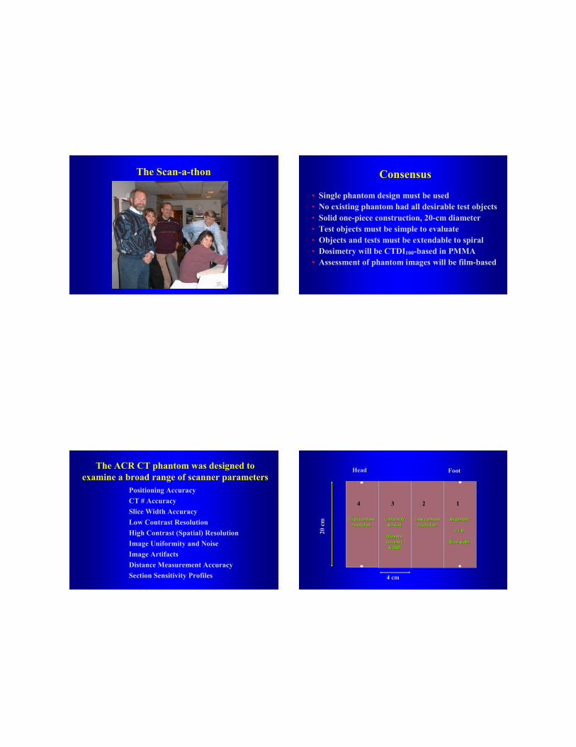
The Scan-a-thon Consensus
• Single phantom design must be used• No existing phantom had all desirable test objects• Solid one-piece construction, 20-cm diameter• Test objects must be simple to evaluate• Objects and tests must be extendable to spiral• Dosimetry will be CTDI100-based in PMMA• Assessment of phantom images will be film-based
The ACR CT phantom was designed to examine a broad range of scanner parameters
• Positioning Accuracy• CT # Accuracy• Slice Width Accuracy• Low Contrast Resolution• High Contrast (Spatial) Resolution• Image Uniformity and Noise• Image Artifacts• Distance Measurement Accuracy• Section Sensitivity Profiles
4 3 2 1
20cm
4 cm
Head Foot
AlignmentAlignment
CT # CT #
Slice widthSlice width
Low contrast Low contrast resolutionresolution
Uniformity Uniformity & noise & noise
Distance Distance accuracy accuracy
& SSP& SSP
High contrast High contrast resolutionresolution
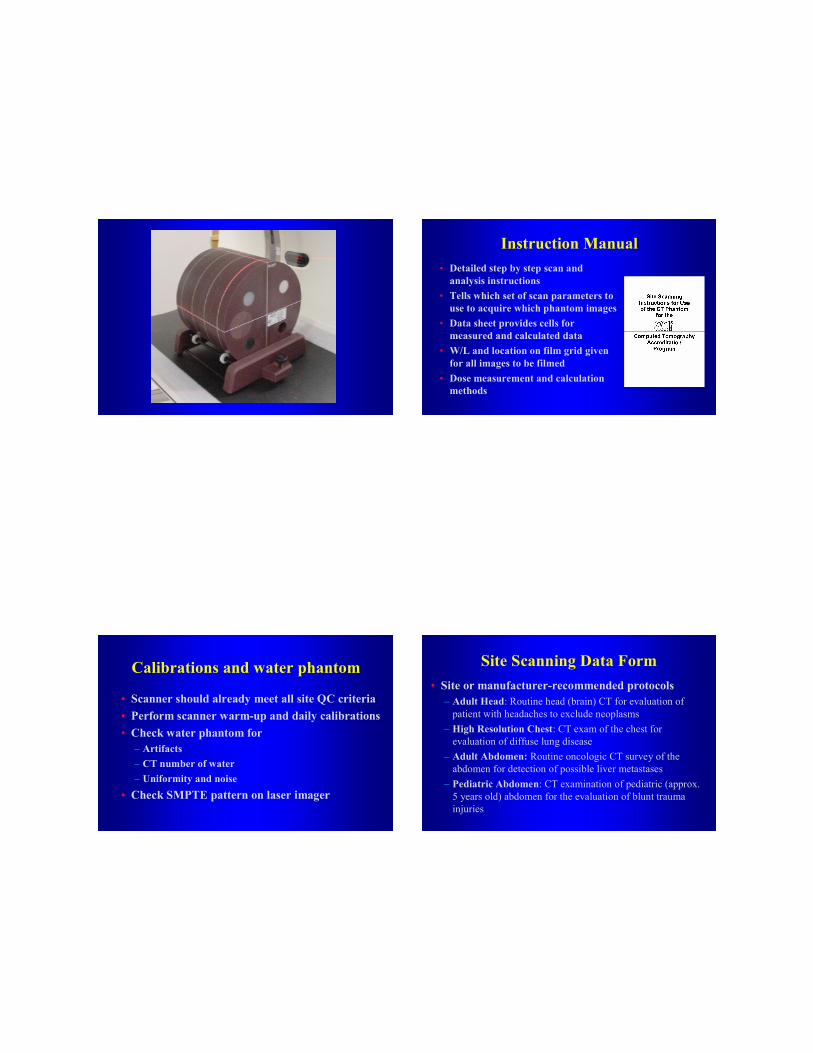
Instruction Manual• Detailed step by step scan and
analysis instructions• Tells which set of scan parameters to
use to acquire which phantom images• Data sheet provides cells for
measured and calculated data• W/L and location on film grid given
for all images to be filmed• Dose measurement and calculation
methods
Calibrations and water phantom
• Scanner should already meet all site QC criteria• Perform scanner warm-up and daily calibrations• Check water phantom for
– Artifacts– CT number of water– Uniformity and noise
• Check SMPTE pattern on laser imager
Site Scanning Data Form• Site or manufacturer-recommended protocols
– Adult Head: Routine head (brain) CT for evaluation of patient with headaches to exclude neoplasms
– High Resolution Chest: CT exam of the chest for evaluation of diffuse lung disease
– Adult Abdomen: Routine oncologic CT survey of the abdomen for detection of possible liver metastases
– Pediatric Abdomen: CT examination of pediatric (approx. 5 years old) abdomen for the evaluation of blunt trauma injuries
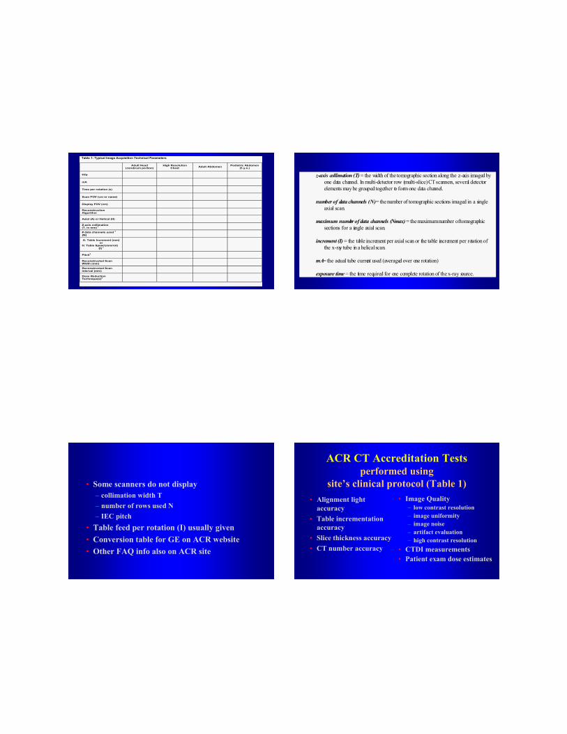
Table 1: Typical Image Acquisition Technical Parameters
Adult Head (cerebrum portion)
High Resolution Chest Adult Abdomen Pediatric Abdomen
(5 y.o.)
kVp
mA
Time per rotation (s)
Scan FOV (cm or name)
Display FOV (cm)
Reconstruction Algorithm
Axial (A) or Helical (H)
Z-axis collimation (T, in mm) 1
# data channels used 1
(N)
A: Table Increment (mm) or
H: Table Speed (mm/rot) (I) 1
Pitch2
Reconstructed Scan Width (mm)
Reconstructed Scan Interval (mm)
Dose Reduction Technique(s)3
z-axis collimation (T) = the width of the tomographic section along the z-axis imaged byone data channel. In multi-detector row (multi-slice) CT scanners, several detectorelements may be grouped together to form one data channel.
number of data channels (N) = the number of tomographic sections imaged in a singleaxial scan.
maximum number of data channels (Nmax) = the maximum number of tomographicsections for a single axial scan.
increment (I) = the table increment per axial scan or the table increment per rotation ofthe x-ray tube in a helical scan.
mA= the actual tube current used (averaged over one rotation)
exposure time = the time required for one complete rotation of the x-ray source.
• Some scanners do not display – collimation width T– number of rows used N – IEC pitch
• Table feed per rotation (I) usually given• Conversion table for GE on ACR website• Other FAQ info also on ACR site
ACR CT Accreditation Tests performed using
site’s clinical protocol (Table 1)• Alignment light
accuracy• Table incrementation
accuracy• Slice thickness accuracy• CT number accuracy
• Image Quality– low contrast resolution – image uniformity– image noise– artifact evaluation – high contrast resolution
• CTDI measurements• Patient exam dose estimates
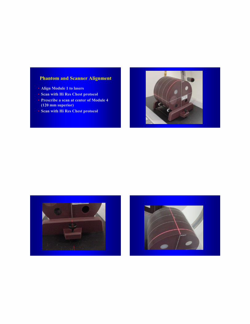
Phantom and Scanner Alignment
• Align Module 1 to lasers• Scan with Hi Res Chest protocol• Prescribe a scan at center of Module 4
(120 mm superior)• Scan with Hi Res Chest protocol
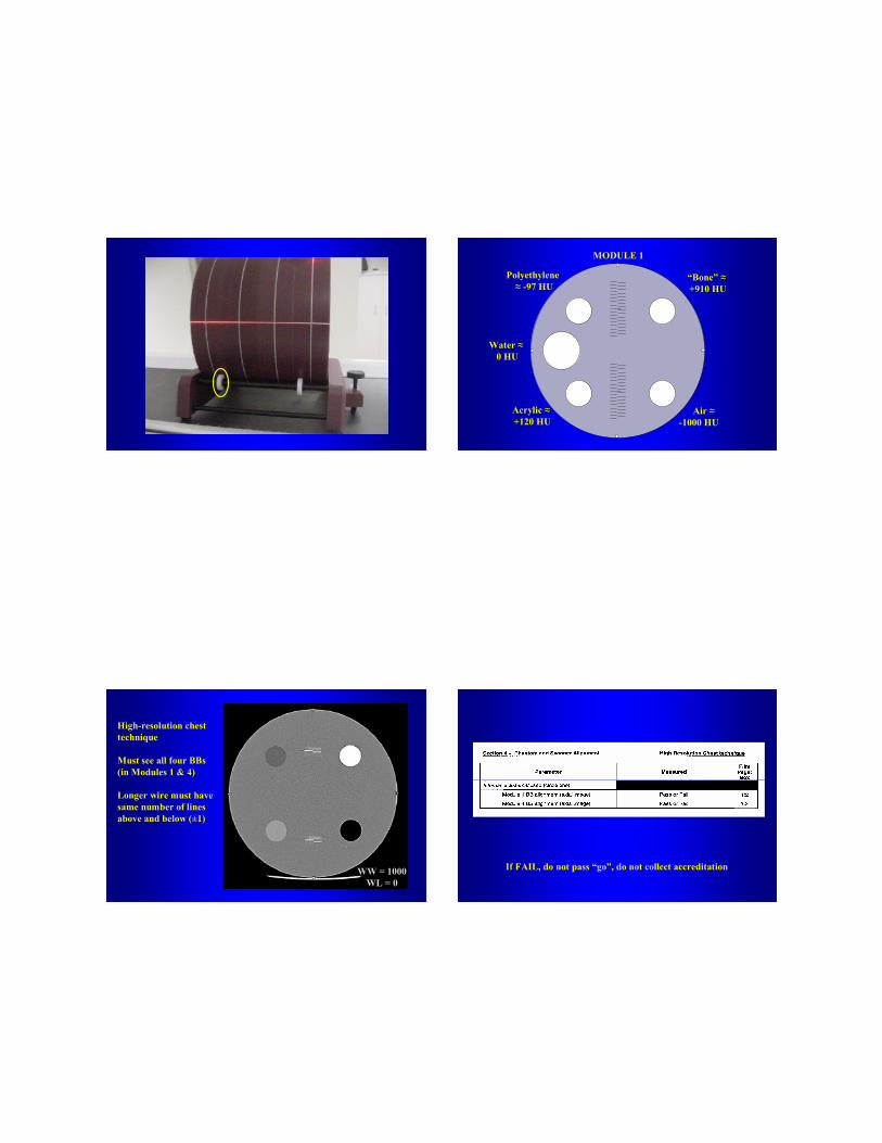
Air ≈-1000 HU
Water ≈0 HU
Polyethylene ≈ -97 HU
“Bone” ≈+910 HU
Acrylic ≈+120 HU
MODULE 1
High-resolution chest technique
Must see all four BBs(in Modules 1 & 4)
Longer wire must have same number of lines above and below (±1)
WW = 1000WL = 0
If FAIL, do not pass “go”, do not collect accreditation
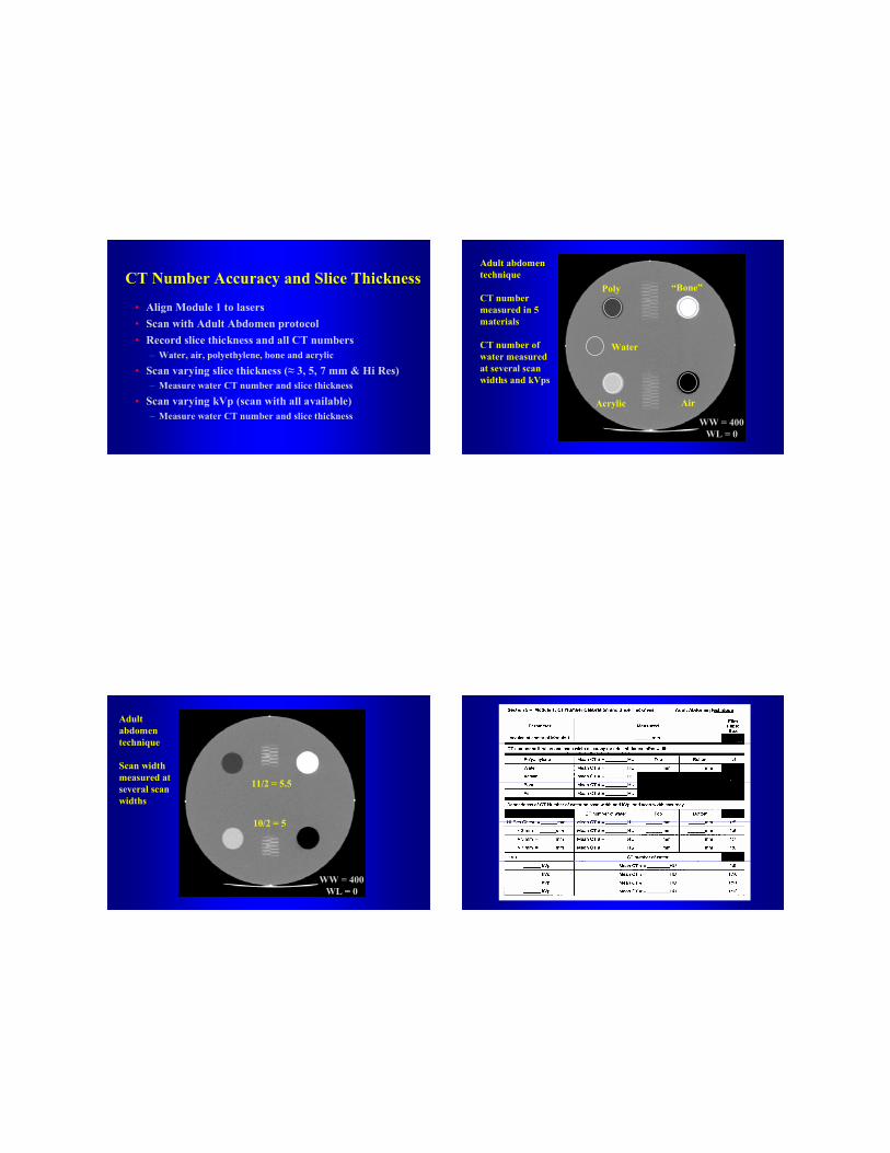
CT Number Accuracy and Slice Thickness
• Align Module 1 to lasers• Scan with Adult Abdomen protocol• Record slice thickness and all CT numbers
– Water, air, polyethylene, bone and acrylic• Scan varying slice thickness (≈ 3, 5, 7 mm & Hi Res)
– Measure water CT number and slice thickness• Scan varying kVp (scan with all available)
– Measure water CT number and slice thickness
Adult abdomen technique
CT number measured in 5 materials
CT number of water measured at several scan widths and kVps
WW = 400WL = 0
“Bone”
Water
Poly
Acrylic Air
11/2 = 5.5
10/2 = 5
Adult abdomen technique
Scan width measured at several scan widths
WW = 400WL = 0
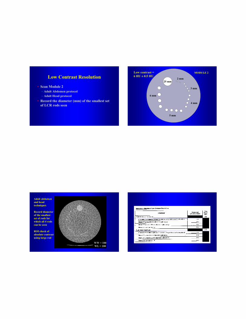
Low Contrast Resolution
• Scan Module 2 – Adult Abdomen protocol– Adult Head protocol
• Record the diameter (mm) of the smallest set of LCR rods seen
25 mm
6 mm
5 mm
4 mm
3 mm
2 mm
Low contrast = 6 HU ± 0.5 HU
MODULE 2
Adult abdomen and head techniques
Record diameter of the smallest set of rods for which all 4 rods can be seen
ROI check of absolute contrast using large rod
WW = 100WL = 100
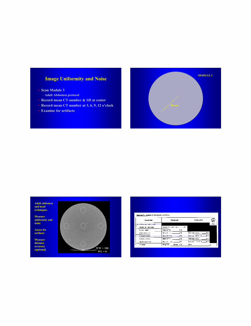
Image Uniformity and Noise
• Scan Module 3– Adult Abdomen protocol
• Record mean CT number & SD at center• Record mean CT number at 3, 6, 9, 12 o’clock• Examine for artifacts
MODULE 3
100 mm
Adult abdomen and head techniques
Measure uniformity and noise
Assess for artifacts
Measure distance accuracy(optional) WW = 100
WL = 0
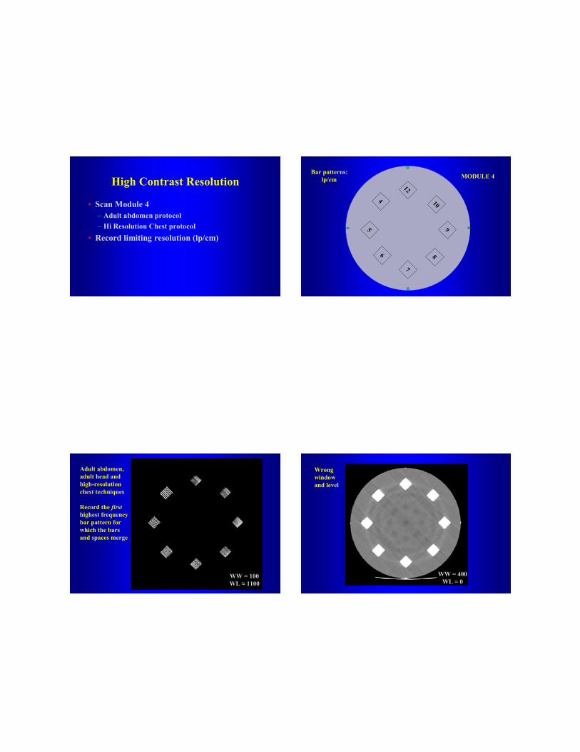
High Contrast Resolution
• Scan Module 4 – Adult abdomen protocol – Hi Resolution Chest protocol
• Record limiting resolution (lp/cm)
12
5 9
46
7
8
10
Bar patterns:lp/cm MODULE 4
Adult abdomen, adult head and high-resolution chest techniques
Record the firsthighest frequency bar pattern for which the bars and spaces merge
WW = 100WL ≈ 1100
WW = 400WL = 0
Wrong window and level
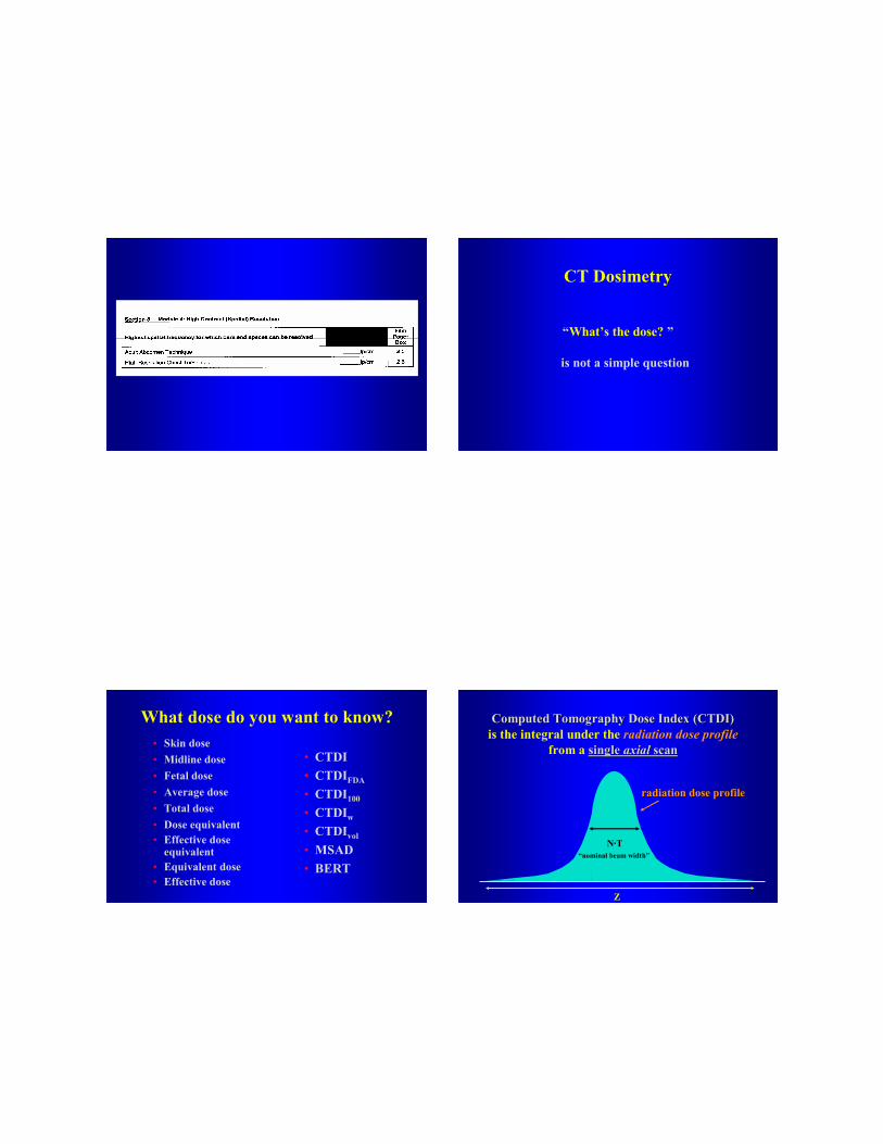
CT Dosimetry
“What’s the dose? ”
is not a simple question
What dose do you want to know?• Skin dose• Midline dose• Fetal dose• Average dose• Total dose
• CTDI• CTDIFDA
• CTDI100
• CTDIw
• CTDIvol
• MSAD• BERT
• Dose equivalent• Effective dose
equivalent• Equivalent dose• Effective dose
Z
radiation dose profile
is the integral under the radiation dose profilefrom a single single axialaxial scanscan
N·T“nominal beam width”
Computed Tomography Dose Index (CTDI)Computed Tomography Dose Index (CTDI)
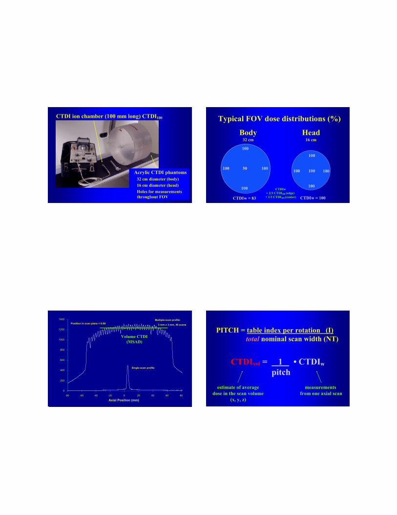
CTDI ion chamber (100 mm long) CTDI100
Acrylic CTDI phantoms32 cm diameter (body)16 cm diameter (head)Holes for measurements throughout FOV
Typical FOV dose distributions (%)
100
100 100
100
50
Body 32 cm
100
100 100
100
100
Head16 cm
CTDIw = 83 CTDIw = 100
CTDIw= 2/3 CTDI100 (edge) + 1/3 CTDI100 (center)
Axial Position (mm)
0
200
400
600
800
1000
1200
1400
-80 -60 -40 -20 0 20 40 60 80
Single-scan profile
Multiple-scan profile:
3 mm x 3 mm, 40 scans Position in scan plane = 6:00
Volume CTDI (MSAD)
PITCH = table index per rotation (I) total nominal scan width (NT)
CTDIvol = 1 • CTDIwpitch
measurements from one axial scan
estimate of averagedose in the scan volume
(x, y, z)
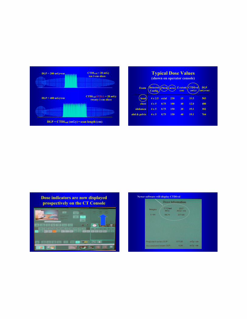
DLP = CTDIvol (mGy) • scan length (cm)
DLP = 200 mGy•cm
DLP = 400 mGy•cm
CTDIvol = 20 mGyten 1-cm slices
CTDIvol STILL = 20 mGytwenty 1-cm slices
Typical Dose Values(shown on operator console)
head 4 x 2.5 axial 230 15 33.5 503
chest 4 x 5 0.75 100 40 12.0 480
abdomen 4 x 5 0.75 150 20 19.1 382
abd & pelvis 4 x 5 0.75 150 40 19.1 764
DetectorConfig.
Z extent(cm)
Exam Pitch mAs CTDIvol(mGy)
DLP(mGy•cm)
Dose indicators are now displayed prospectively on the CT Console
Newer software will display CTDIvol
vol
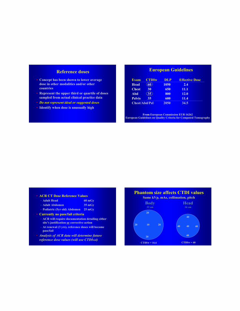
Reference doses• Concept has been shown to lower average
dose in other modalities and/or other countries
• Represent the upper third or quartile of doses sampled from actual clinical practice data
•• Do not represent ideal or suggested dosesDo not represent ideal or suggested doses• Identify when dose is unusually high
European Guidelines
Exam CTDIw DLP Effective DoseHead 60 1050 2.4Chest 30 650 11.1Abd 35 800 12.0Pelvis 35 600 11.4Chest/Abd/Pel 2050 34.5
From European Commission EUR 16262European Guidelines on Quality Criteria for Computed Tomography
• ACR CT Dose Reference Values– Adult Head 60 mGy– Adult Abdomen 35 mGy– Pediatric (5yr old) Abdomen 25 mGy
• Currently no pass/fail criteria– ACR will require documentation detailing either
site’s justification or corrective action– At renewal (3 yrs), reference doses will become
pass/fail
•• Analysis of ACR data will determine future Analysis of ACR data will determine future reference dose values (will use CTDIreference dose values (will use CTDIvolvol))
Phantom size affects CTDI valuesSame Same kVpkVp,, mAsmAs, collimation, pitch, collimation, pitch
20
20 20
20
10
Body Body 32 cm32 cm
40
40 40
40
40
HeadHead16 cm16 cm
CTDIw = 16.6 CTDIw = 40
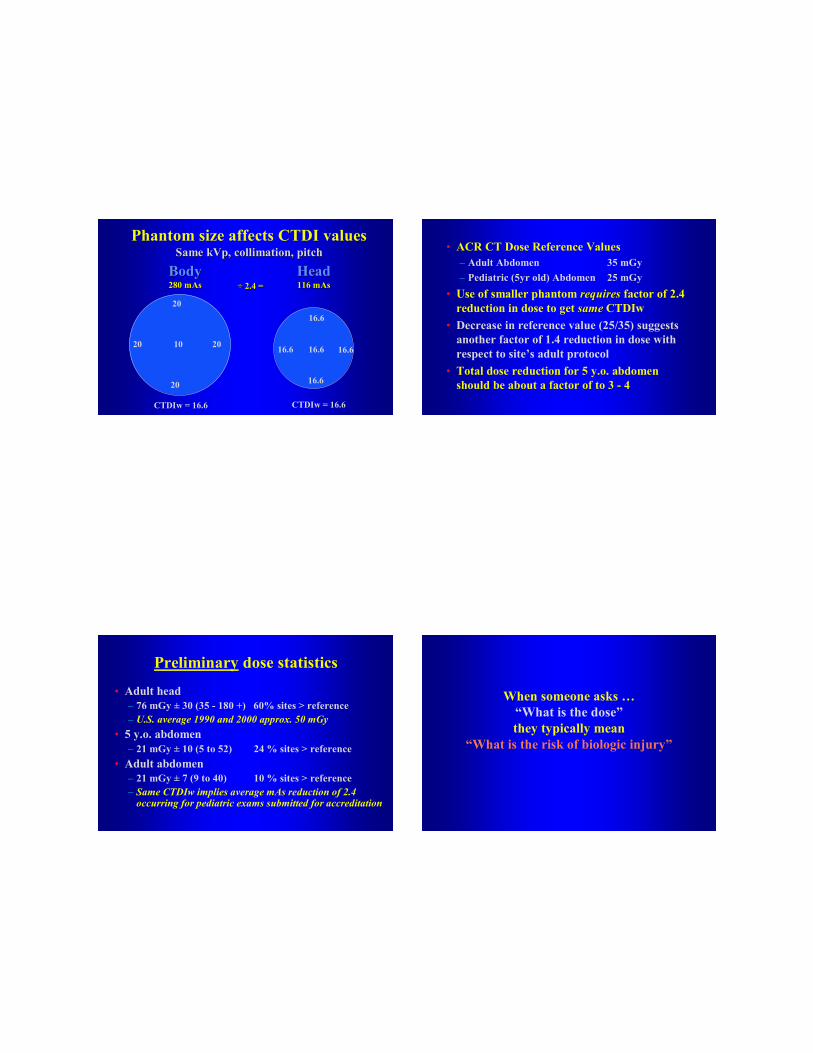
Phantom size affects CTDI valuesSame Same kVpkVp, collimation, pitch, collimation, pitch
20
20 20
20
10
Body Body 280280 mAsmAs
16.6
16.6 16.6
16.6
16.6
HeadHead116 116 mAsmAs
CTDIw = 16.6 CTDIw = 16.6
÷÷ 2.4 =2.4 =
• ACR CT Dose Reference Values– Adult Abdomen 35 mGy– Pediatric (5yr old) Abdomen 25 mGy
• Use of smaller phantom requiresrequires factor of 2.4 reduction in dose to get samesame CTDIw
• Decrease in reference value (25/35) suggests another factor of 1.4 reduction in dose with respect to site’s adult protocol
• Total dose reduction for 5 y.o. abdomen should be about a factor of to 3 - 4
Preliminary dose statistics
• Adult head– 76 mGy ± 30 (35 - 180 +) 60% sites > reference– U.S. average 1990 and 2000 approx. 50 mGy
• 5 y.o. abdomen– 21 mGy ± 10 (5 to 52) 24 % sites > reference
• Adult abdomen– 21 mGy ± 7 (9 to 40) 10 % sites > reference– Same CTDIw implies average mAs reduction of 2.4
occurring for pediatric exams submitted for accreditation
When someone asks …“What is the dose”they typically mean
“What is the risk of biologic injury”
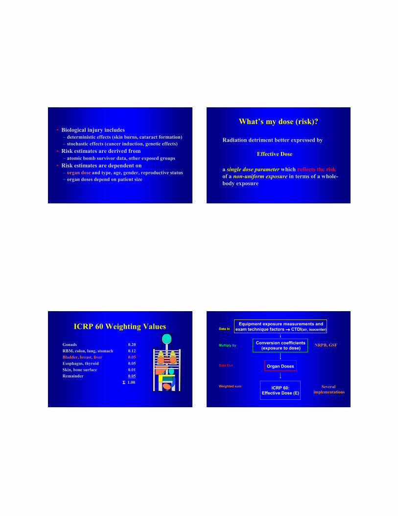
• Biological injury includes – deterministic effects (skin burns, cataract formation)– stochastic effects (cancer induction, genetic effects)
• Risk estimates are derived from– atomic bomb survivor data, other exposed groups
• Risk estimates are dependent on– organ dose and type, age, gender, reproductive status– organ doses depend on patient size
What’s my dose (risk)?
Radiation detriment better expressed by
Effective Dose
a single dose parameter which reflects the riskof a non-uniform exposure in terms of a whole-body exposure
ICRP 60 Weighting Values
Gonads 0.20RBM, colon, lung, stomach 0.12Bladder, breast, liver 0.05Esophagus, thyroid 0.05Skin, bone surface 0.01Remainder 0.05
ΣΣΣΣ 1.00
Equipment exposure measurements and exam technique factors →→→→ CTDI(air, isocenter)Data In
Data Out Organ Doses
Multiply by Conversion coefficients(exposure to dose) NRPB, GSF
ICRP 60:Effective Dose (E)
Weighted sum Several implementations
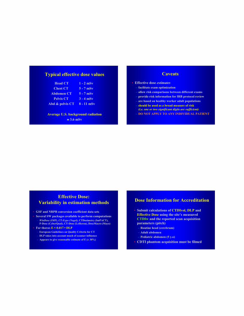
Typical effective dose values
Average U.S. background radiation ≈≈≈≈ 3.6 mSv
Head CT 1 - 2 mSvChest CT 5 - 7 mSv
Abdomen CT 5 - 7 mSvPelvis CT 3 - 4 mSv
Abd & pelvis CT 8 - 11 mSv
• Effective dose estimates– facilitate exam optimization– allow risk comparisons between different exams– provide risk information for IRB protocol review– are based on healthy worker adult populations– should be used as a broad measure of risk
(i.e. one or two significant digits are sufficient)– DO NOT APPLY TO ANY INDIVIDUAL PATIENT
Caveats
Effective Dose:Variability in estimation methods
• GSF and NRPB conversion coefficient data sets• Several SW packages available to perform computations
– WinDose (IMP), CT-Expo (Nagel), CTDosimetry (ImPACT), P-Dose (CyberQual), CT-Dose (LeHeron), DoseMacro (Mayo)
• For thorax E ≈ 0.017 • DLP– European Guidelines on Quality Criteria for CT– DLP takes into account much of scanner influence– Appears to give reasonable estimate of E (± 30%)
Dose Information for Accreditation
• Submit calculations of CTDIvol, DLP and Effective Dose using the site’s measured CTDIw and the reported scan acquisition parameters (pitch)– Routine head (cerebrum)– Adult abdomen– Pediatric abdomen (5 y.o)
• CDTI phantom acquisition must be filmed
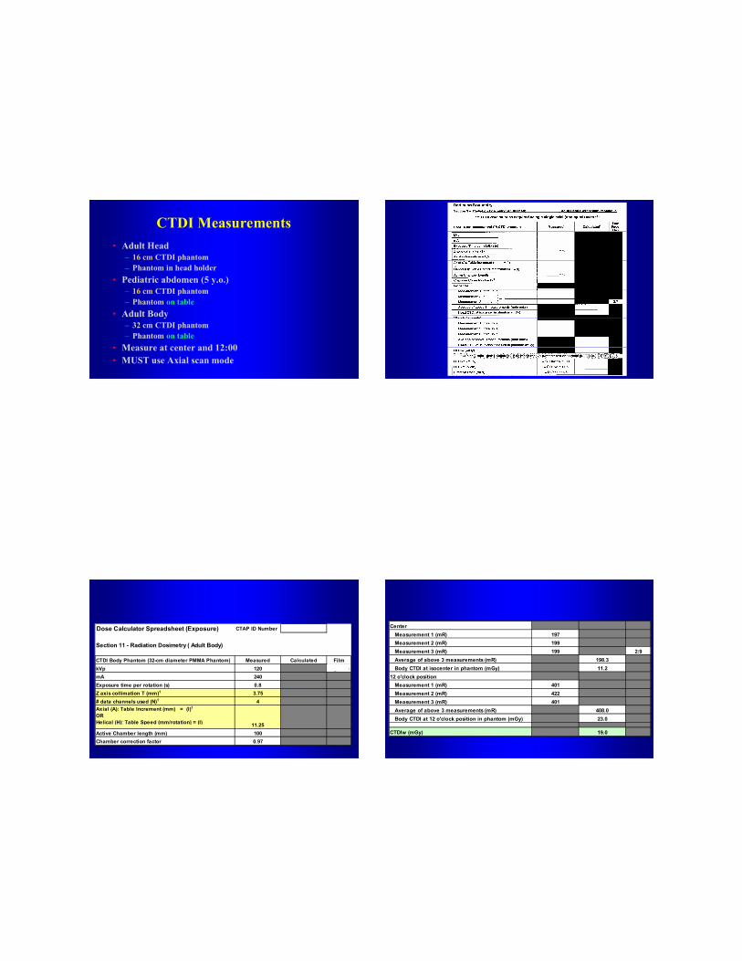
CTDI Measurements• Adult Head
– 16 cm CTDI phantom– Phantom in head holder
• Pediatric abdomen (5 y.o.)– 16 cm CTDI phantom– Phantom on table
• Adult Body– 32 cm CTDI phantom– Phantom on table
• Measure at center and 12:00• MUST use Axial scan mode
Dose Calculator Spreadsheet (Exposure) CTAP ID Number 00019
Section 11 - Radiation Dosimetry ( Adult Body)
CTDI Body Phantom (32-cm diameter PMMA Phantom) Measured Calculated FilmkVp 120 Page:BoxmA 240Exposure time per rotation (s) 0.8Z axis collimation T (mm)1 3.75# data channels used (N)1 4Axial (A): Table Increment (mm) = (I)1OR Helical (H): Table Speed (mm/rotation) = (I) 11.25Active Chamber length (mm) 100Chamber correction factor 0.97
Center Measurement 1 (mR) 197 Measurement 2 (mR) 199 Measurement 3 (mR) 199 2:9 Average of above 3 measurements (mR) 198.3 Body CTDI at isocenter in phantom (mGy) 11.212 o'clock position Measurement 1 (mR) 401 Measurement 2 (mR) 422 Measurement 3 (mR) 401 Average of above 3 measurements (mR) 408.0 Body CTDI at 12 o'clock position in phantom (mGy) 23.0
CTDIw (mGy) 19.0
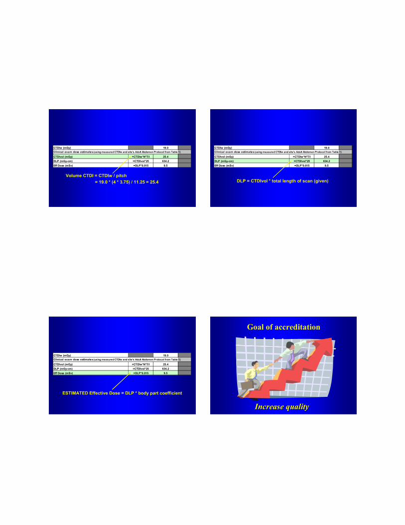
CTDIw (mGy) 19.0Clinical exam dose estimates (using measured CTDIw and site's Adult Abdomen Protocol from Table 1)
CTDIvol (mGy) =CTDIw*N*T/I 25.4DLP (mGy-cm) =CTDIvol*25 634.2Eff Dose (mSv) =DLP*0.015 9.5
Volume CTDI = CTDIw / pitch= 19.0 * (4 * 3.75) / 11.25 = 25.4
CTDIw (mGy) 19.0Clinical exam dose estimates (using measured CTDIw and site's Adult Abdomen Protocol from Table 1)
CTDIvol (mGy) =CTDIw*N*T/I 25.4DLP (mGy-cm) =CTDIvol*25 634.2Eff Dose (mSv) =DLP*0.015 9.5
DLP = CTDIvol * total length of scan (given)
CTDIw (mGy) 19.0Clinical exam dose estimates (using measured CTDIw and site's Adult Abdomen Protocol from Table 1)
CTDIvol (mGy) =CTDIw*N*T/I 25.4DLP (mGy-cm) =CTDIvol*25 634.2Eff Dose (mSv) =DLP*0.015 9.5
ESTIMATEDESTIMATED Effective Dose = DLP * body part coefficient
Goal of accreditation
Increase qualityIncrease quality

From head … to toe …
We need to keep our eyes on quality! For further information contact the ACR