GO fermentor manual081115 · ! ! 3!! 2. COMPONENTS’!...
41
GOfermentor Operating Manual
Transcript of GO fermentor manual081115 · ! ! 3!! 2. COMPONENTS’!...

GOfermentor Operating Manual

2
GOfermentor is a trademark. US and foreign patents pending.
Operating Manual ©2015
Preliminary version 0.07 August 2015
www.GOfermentor.com

CONTENTS
1. What is the GOfermentor ? ................................................................................................................................... 1
2. Components .......................................................................................................................................................... 3
3. Installation ............................................................................................................................................................. 4
3.1 What you need to provide ? ................................................................................................................................ 4
3.2 What do you need to order from us ? ................................................................................................................. 4
3.3 Equipment setup ................................................................................................................................................. 5
4. Red wine operations ........................................................................................................................................... 10
5. White Wine Operations ....................................................................................................................................... 17
6. Operation of Controls .......................................................................................................................................... 20
6.1 Basic controller operation ......................................................................................................................... 21
6.2 PRO controller operation ............................................................................................................................ 22
APPENDIX .................................................................................................................................................................... 26
A1. SPECIFICATIONS ................................................................................................................................................ 27
A2. Control panel assembly instructions ................................................................................................................. 32
A3. Troubleshooting Alarms and Errors .................................................................................................................. 33
A4. PRO CONTROLLER CONFIGURATION/SETUP ..................................................................................................... 34
A5. GOCOOLER assembly instructions .................................................................................................................... 36
A6. Warranty, Liability, and Returns Policy ............................................................................................................. 37


1
1. WHAT IS THE GOFERMENTOR ?
Introducing the first really revolutionary device for winemaking. Traditional winemaking fermentors have changed little in the last 500 years -‐ the only major change being the move from open wood vats to temperature controlled stainless-‐steel tanks. The GOfermentor brings 21st century technology, developed originally for the manufacture of pharmaceuticals, to modern winemaking. This technology dramatically reduces the capital and operating cost for a winery. No significant installation is necessary – a fermentation system can be set up within minutes in any suitable room. No cleaning is required which dramatically reduces labor requirements. No waste water treatment is needed as the process uses essentially no wash water. And, finally, the GOfermentor provides better control of fermentation parameters, minimal exposure to air, and automated cap management, thereby reliably producing a better quality wine.
The GOfermentor currently available has a nominal volume of 1000 liters. This can be used for a batch size ranging from 200lbs to 1 ton of grapes per run. This makes it ideal for small winery operations and also for experimental runs in large wineries. It can be used for either red or white wine production. In the case of red wine, the integral punch system manages the cap, and is also used at completion of fermentation to press out the wine. With white wine, the punch system is used to press out the grape juice prior to fermentation and can later also be used for bâtonage.
The GOfermentor provides a more controlled environment than fermentation in an open bin. The single-‐use fermentation bag is delivered clean, and the fermentation is performed entirely inside this sealed environment. This minimizes potential contamination. Even punch-‐down of the cap is done without exposing the fermenting must to air. The built-‐in punch system can operate automatically and it ensures that the cap remains moist while maximum flavor and color is extracted under control of the winemaker. The punch system is coupled with a strainer assembly to function as a very effective bladder press, eliminating the need for a dedicated press in the winery.
Optional accessories allow the monitoring and control of temperature. This enables each fermentation to be conducted at its optimal temperature.
The GOfermentor eliminates the high capital and installation cost of conventional stainless steel fermentation tanks. Minimal capital and operating labor costs are obvious advantages over the traditional fixed stainless-‐steel tanks. But, often overlooked is the cost and environment impact of washing. Conventional fermentation tanks must be thoroughly washed before and after use. This requires the use of polluting detergents, physical scrubbing, and lots and lots of rinse water. It is estimate that rinse water typically accounts for 3-‐7X the tank volume. Washing a 300 gallon fermentation tank wastes 900 to 2100 gallons of fresh water. With the GOfermentor, there is no wash water usage. The reusable outer container does not contact the must so a simple wipe down is sufficient. The fermentation liner is delivered empty, clean, and folded. These liners are made of USP grade plastics which are free from plastizers/leachables and are certified for use in pharmaceutical operations. There is no need to rinse or clean this liner before use. After the wine is pressed out at the end of the fermentation the liner contains the residual pomace . The entire liner can be taken to the vineyard and the pomace dumped back as a natural fertilizer for the vines as it is not contaminated with any detergents. The empty used liner can simply be sent to municipal landfill where it quickly biodegrades. The used liner does not contain any hazardous or toxic chemicals.

2
BENEFITS
The GOFermentor provides many benefits to the winery:
1. A clean and closed environment for the fermentation. No open operations result in minimal oxidation. This also can reduce the need to add sulfites.
2. Minimal capital expenditures. All product contact components are single-‐use. 3. Single-‐use design eliminates cleaning with a huge reduction in water consumption. 4. Integral automated punch ensures proper cap management with excellent flavor and color extraction. 5. Integral press design eliminates the need for labor intensive pressing and cleaning. Pressing can be done
without any air contact. Eliminates the need for a costly press and water usage to clean it. 6. A truly “waterless” wine production system. 7. Portable clean operation. Grapes can be destemmed and crushed at the vineyard and pumped into the
GOfermentor. Truck the filled GOfermentor to the winery and start the fermentation. All the mess and cleaning is confined to just the vineyard.
8. Urban microwineries – the GOfermentor makes the urban microwinery possible. All you need is a garage or warehouse space.

3
2. COMPONENTS
The GOfermentor consists of two major components:
1. GOBASE -‐ Reusable outer container with control panel – This rigid plastic container holds the fermentation bag in position. The container can be moved by pallet jack or forklift. It is also DOT certified for truck shipment. Since the wine does not contact the outer container, it can be reused between batches by simply wiping down the surfaces. The container also folds down for storage when not in use. A panel with electrical components, inflation pump, and valves attaches to the rigid container for automatic control of punch, temperature, and other functions.
2. GOLINER -‐ Single-‐use Fermentation Liner – The fermentation is conducted entirely inside a flexible plastic liner. This liner has 2 chambers – a primary chamber where the fermenting must is contained, and a secondary chamber that is solely used for inflation. The two chambers share a common wall, but it is very important to note that the air used to inflate the second chamber does in no way come in contact with the fermenting must in the primary chamber. The GOLINER is supplied clean and ready for use. It is intended for only one use.

4
3. INSTALLATION
The GOfermentor is designed to be portable and there is essentially no installation other than placing the unit in position and connecting to a standard electrical receptacle.
3.1 WHAT YOU NEED TO PROVIDE ?
• Floor space 48x48inches by 60inches height. Minimum doorway width 46 inches. • Pallet jack or truck to move 225 lb (89Kg) GOBASE unit. • Standard household-‐type electric service 110 VAC 10amp. Standard household plug. • Must pump or similar device to fill and drain GOLINER through 2inch TriClamp ports. • Chilled water or glycol supply if using optional GOCOOLER heat exchanger plate.
3.2 WHAT DO YOU NEED TO ORDER FROM US ?
REQUIRED
• GOFERMENTOR BASIC or GOFERMENTOR PRO • GOLINER single-‐use dual chamber fermentation liners. Need one per run. Sold in cases of 3.
OPTIONAL
• GOSTRAINER option to best utilize the pressing capabilities of the GOfermentor (recommended). • GOCOOLER heat exchanger plate for temperature control (requires PRO controller).

5
3.3 EQUIPMENT SETUP
Setting up the GOfermentor for winemaking is very easy and should take less than 15 minutes. First set up the rigid GOBASE unit. Then install the single-‐use GOLINER.
GOBASE
1. Set the rigid GOBASE in a suitable area. Open the folded sides and push them until they lock in place. 2. Check that there is no debris inside the GOBASE that might damage the GOLINER. 3. Assemble the support rail and hose support pole to the control panel (Appendix A2). 4. Using the support rail hang the control panel on the front of the GOBASE. The front of the GOBASE is the
side with the bottom discharge port. Just place the support rail mounting holes over the corresponding posts in the GOBASE as shown below and let the control panel hang against the front of the GOBASE.

6
OPTIONAL GOCOOLER HEAT EXCHANGER PLATE
For temperature control, the optional GOCOOLER heat exchanger plate is necessary. It also requires the GOfermentor PRO controller.
1. Assemble the coolant pipes on to the heat exchanger plate (Appendix A5). 2. Place the GOCOOLER on the bottom of the GOBASE with the vertical coolant lines at the back as shown
below. You can place the cooling on the left or right side of the central drain outlet. You can even place two cooling plates in the GOBASE. The GOLINER will be placed direct on top of the heat exchanger plate.
3. Connect a coolant inlet hose (user-‐supplied) to the control valve (1/2” NPT) and the coolant return hose (also user-‐supplied) to the outlet fitting (also ½” NPT).

7
GOLINER
1. Remove the GOLINER carefully from its packaging. Remove and discard any packing materials. 2. Place the GOLINER inside the GOBASE. The GOLINER has 3 ports:
a. TOP FILL PORT: This port is used to fill the liner, to make additions and to sample the GOLINER. It should face up and be positioned towards the front.
b. BOTTOM DRAIN PORT: This port has a built-‐in valve and locking collar. It will be installed in the bottom drain fitting on the front of the GOBASE.
c. INFLATION PORT: This port is used to inflate the secondary chamber of the GOLINER. It is located in the blue section of the GOLINER and marked AIR ONLY. It should face towards the rear (away from the GOBASE bottom discharge port).
3. Reach inside the GOBASE bottom discharge opening and pull the BOTTOM DRAIN PORT towards you. Pull until the tabs on either side of the BOTTOM DRAIN PORT lock into the corresponding ribs on the GOBASE as shown below.
Make sure tabs are locked into the grooves on either side !
NOTE – the valve flange is flush against the back of this rib
BOTTOM port – note the tamperproof collar and red cap have been removed to better show the locking tabs
BOTTOM port – CLOSED (red handle left) – OPEN (red handle right)

8
4. Pull up on the INFLATION PORT and secure it with a bungee cord so that is it draped against the rear wall on the GOBASE. This is important because if the INFLATION PORT gets trapped underneath the liner during filling, it will not be possible to reposition it once the GOLINER is full.
5. Remove the shipping cap and screw the MBSP2CM inflation port adaptor onto the INFLATION PORT. This adaptor has several tangential holes and couples to the camlock connector on the inflation hose.
6. Remove the shipping cap from the TOP port and screw on the MBSP2TC TriClamp adaptor. Take care not to cross-‐thread this port and ensure that it is screwed in all the way so that the rubber O-‐ring is snug against the GOLINER port as shown below.
7. Remove the red cap from the BOTTOM PORT and screw on the DN502TC TriClamp adaptor. This will enable you to connect a 2” TriClamp drain/pressing hose later.
MBSP2CM adaptor
MBSP2TC adaptor
DN502TC adaptor

9
You have completed the GOLINER installation and are ready to fill it with crushed grapes. The next operations are different depending on if you are making red wine or white wine.

10
4. RED WINE OPERATIONS
The GOfermentor must first be setup as described earlier in Section 3.3.
FILLING WITH MUST
1. Connect a destemmer to the TOP FILL port of the GOLINER. Use a kink-‐free hose with a 2inch TriClamp fitting.
2. Run the destemmer/crusher and use its internal pump to transfer the required amount of crushed grapes into the GOLINER (max 1 ton).
3. Disconnect the fill hose. Connect the included Triclamp cap to the FILL PORT to prevent spillage.
NOTE: DO NOT ATTEMPT to fill the liner from the BOTTOM DRAIN PORT. This is impossible.
CONNECT THE VENT AND INFLATION HOSES
1. Remove the Triclamp cap from the FILL PORT and connect the included HEAD2TC sampler/temperature probe to the TOP port using a gasket and TriClamp.
2. Connect the vent hose (CLEAR) to the camlock connector on the HEAD2TC sampler/temperature. Connect the other end of this hose to the valve inlet located at the front bottom of the control panel. The hose should be clamped to the support pole and pulled up so that the TOP port is level with the top of the GOBASE container as shown on the next page. Secure the hose on the support pole bracket so that it cannot slide in the clamp.

11
3. Connect the inflation hose (BLUE) to the camlock adaptor on the INFLATION port (located on the BLUE chamber). Connect the other end of the INFLATION hose to the blower outlet located on the right side of the control panel.
CONNECT THE TEMPERATURE PROBE/SAMPLING TUBE
1. Connect the temperature probe wire to the jack located on the top right of the control panel. 2. Power up the control panel and verify that it is operational and that temperature is displayed. 3. Power up the control panel and verify that it is operational and that temperature is displayed.
BLUE inflation hose
CLEAR vent hose
HEAD2TC vent connector
Pressure relief valve
3 WAY valve
12”
HEAD2TC sampler/temperature

12
SAMPLING
Sampling is performed by connecting the supplied sampling syringe. Push the quick-‐connect coupler on the tubing attached to the syringe onto the mating socket on the sampling tube. This will open the flow path to the syringe. Now simply draw the sample into the syringe. Disconnect the sampler by pressing the release button on the mating socket. The mating socket has an internal valve that automatically shuts off when it is not connected to the sampler.
MUST ADJUSTMENT
1. Samples of the must may be taken from the TOP port and any additions can be made by opening the TriClamp and lifting up the sampling tube. The sampling tube can also be removed to facilitate additions using a funnel if necessary.
2. Inoculation with yeast is also done through the TOP port.
INITIAL OXYGENATION
1. Usually sufficient oxygen is introduced during the fill, but additional oxygen can be added to the must in order to get vigorous yeast growth after inoculation.
2. This can be done by connecting a tube (with connection adaptor) to the sampler fitting and blowing air into the fermentor. In this manner, the air is introduced near the bottom ensuring efficient oxygenation.
Draw syringe to fill
Connect to open sample path

13
PUNCH OPERATION
Punch of the cap may be initiated at any time in the fermentation. It can also be performed after initial must adjustment to mix all the additions and to disperse the yeast if desired.
To perform the punch operation using the BASIC controller:
1. The PUNCH button should be illuminated indicating that the unit is ready for punching. Press the PUNCH button to initiate the punch cycle.
2. The PUNCH button will start flashing indicating that a punch is now in progress. You can press the flashing PUNCH button at any time to instantly cancel the punch.
3. The controller will switch the GOLINER vent to exhaust the fermentation chamber to the atmosphere and it will start to deflate. After about 30 seconds the blower will come on and the secondary chamber will inflate forcing the fermentation chamber upwards. This in turn forces the liquid in the fermentation chamber up and also squeezes the cap. At a preset pressure, the blower will turn off and the secondary chamber will deflate. After 10 seconds or so the blower will come on again and this cycle will repeat for the preset punch time (typically 1 minute).
4. The system will then reset, and the GOLINER vent will switch to the pressure relief valve (PRV) position and the fermentation chamber will slowly reinflate with the CO2 generated by the fermentation.
The punch process is exactly the same when using the PRO controller, except that the PUNCH is initiated by a graphic button on the touch panel. Pressing this graphic button once the punch is underway will cancel the operation as described for the BASIC controller. The PRO controller also enables the punch to be done automatically on a user-‐set schedule. Timing and duration of the punch cycle can also be adjusted. The PRO also records all punch cycles on its event log so that a complete history of the run is maintained. Details on how to change these parameters are provided in Appendix A4.
14
NOTE: You may need to adjust the PUNCH pressure setpoint depending on the must volume (SETUP-‐>PUNCH). For small volumes 10”H2O is good, while for a large volume (> 600Kg) you should use a higher pressure (20”H2O) to get an effective punch.
TEMPERATURE MONITORING
Temperature is monitored continuously by a probe positioned in the center and about 8 inches from the bottom. This is typically the hottest point in the fermentor. Temperature can be displayed in either degrees C or F (Section 6).The temperature probe uses an advanced digital sensor that never needs to be recalibrated. The PRO controller also has the ability to control temperature by regulating flow of coolant through the optional GOCOOLER heat exchanger plate.
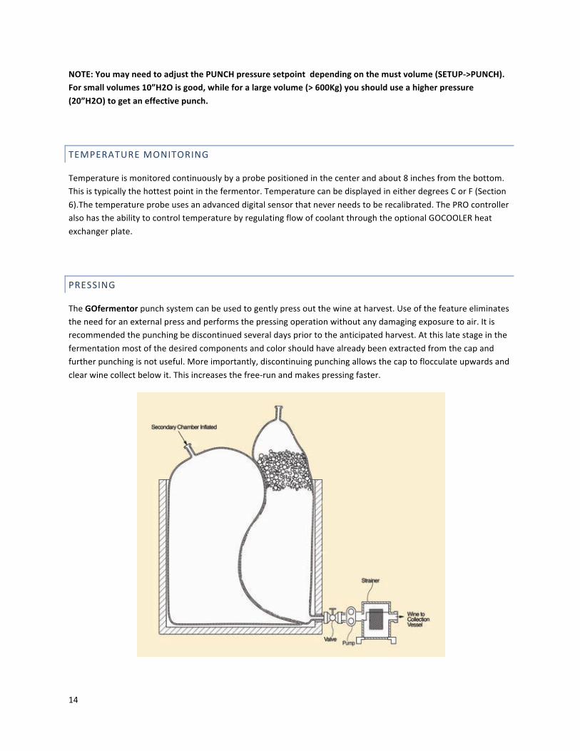
PRESSING
The GOfermentor punch system can be used to gently press out the wine at harvest. Use of the feature eliminates the need for an external press and performs the pressing operation without any damaging exposure to air. It is recommended the punching be discontinued several days prior to the anticipated harvest. At this late stage in the fermentation most of the desired components and color should have already been extracted from the cap and further punching is not useful. More importantly, discontinuing punching allows the cap to flocculate upwards and clear wine collect below it. This increases the free-‐run and makes pressing faster.

15
1. Connect the BOTTOM port to the inlet of a must pump using the 2inch TriClamp adaptor. Use a crush-‐proof reinforced hose rated for vacuum.
2. Using another hose connect the outlet of the must pump to the inlet of the GOSTRAINER. Using a third hose, connect the outlet of the GOSTRAINER to a collection liner, tank, or barrel. The pressed wine will be collected in this container for post-‐fermentation operations.
3. Open the GOSTRAINER and remove the basket. Check that the included mesh liner is in the basket. This mesh liner will make removing the pomace later much easier. Place the basket back into the GOSTRAINER and secure the top cover.
4. Now open the GOLINER DRAIN valve by pushing the integral valve handle all the way to the right. Open all valves through the pump all the way to the collection vessel. You should immediately see a flow of free-‐run wine.
5. Start the must pump to increase the flow, however avoid pumping too fast as this will draw in the cap. If you do not get any flow – there may be air in the strainer causing an airlock. Carefully open the vent valve located in the strainer cover to vent out this trapped air. Close the vent once you have liquid flow.
6. Once the free run flow stops you can start to press out the liquid in the cap. At this stage initiate the punch operation to squeeze the cap gently to press out the wine. The punch operation can be done several times during the pressing to get as much wine as desired out of the cap.
7. The GOSTRAINER will clog as it fills up with seeds and skins. When this occurs, shut down the flow and close the valves to isolate the GOSTRAINER. Open the top cover and remove the basket. Pull out the mesh liner and scrape off the pomace. Rinse the mesh liner and replace it in the basket. Reinstall the basket, open the isolation valves and continue the pressing. The basket cleanout should not take more than 5 minutes and it may need to be done 2 or 3 times depending on the fermentation volume.
8. When it evident that no more wine can be pressed out, the pressing is stopped. Close the GOLINER DRAIN valve by pushing the handle all the way to the left. Disconnect the must pump and GOSTRAINER.
Mesh liner

16
DISPOSAL
At the end of pressing a tight mass of skins and seeds will remain in the GOLINER. Using a suitable device, lift the GOLINER out of the GOBASE. The GOLINER may be taken to the vineyard and slit open to disperse the pomace as fertilizer. The empty GOLINER is then simply folded up and discarded as household waste. There are no toxic chemicals in the used GOLINER and it will rapidly biodegrade in a landfill. The GOBASE never contacts the must so it can simply be wiped down and setup with a new GOLINER for the next fermentation.
17
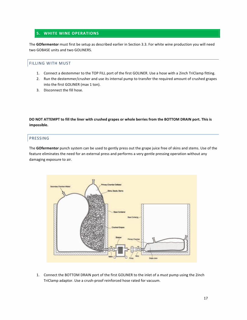
5. WHITE WINE OPERATIONS
The GOfermentor must first be setup as described earlier in Section 3.3. For white wine production you will need two GOBASE units and two GOLINERS.
FILLING WITH MUST
1. Connect a destemmer to the TOP FILL port of the first GOLINER. Use a hose with a 2inch TriClamp fitting. 2. Run the destemmer/crusher and use its internal pump to transfer the required amount of crushed grapes
into the first GOLINER (max 1 ton). 3. Disconnect the fill hose.
DO NOT ATTEMPT to fill the liner with crushed grapes or whole berries from the BOTTOM DRAIN port. This is impossible.
PRESSING
The GOfermentor punch system can be used to gently press out the grape juice free of skins and stems. Use of the feature eliminates the need for an external press and performs a very gentle pressing operation without any damaging exposure to air.
1. Connect the BOTTOM DRAIN port of the first GOLINER to the inlet of a must pump using the 2inch TriClamp adaptor. Use a crush-‐proof reinforced hose rated for vacuum.

18
2. Using another hose connect the outlet of the must pump to the inlet of the GOSTRAINER. Using a third hose, connect the outlet of the GOSTRAINER to the BOTTOM or TOP port of the second GOLINER. The pressed grape juice will be collected and then fermented in this second GOLINER.
3. Open the GOSTRAINER and remove the basket. Check that the included mesh liner is in the basket. This will make removing the skins and seeds later much easier. Place the basket back into the GOSTRAINER and secure the top cover.
4. Now open the GOLINER DRAIN valve by pushing the integral valve handle all the way to the right. Open all valves through the pump all the way to the second GOLINER.
5. Start the must pump to transfer the grape juice. Press the PUNCH button periodically to press the juice out of the mass of skins,seeds, and juice in the GOLINER.
6. The GOSTRAINER will clog as it fills up with seeds and skins. When this occurs, shut down the flow and close the valves to isolate the GOSTRAINER. Open the top cover and remove the basket. Pull out the mesh liner and scrape off the accumulated debris. Rinse the mesh liner and replace it in the basket. Reinstall the basket, open the isolation valves and continue the pressing. The basket cleanout should not take more than 5 minutes and it may need to be done 2 or 3 times depending on the volume to be processed
7. When it evident that no more juice can be pressed out, the pressing is stopped. Close the GOLINER DRAIN valve by pushing the handle all the way to the left. Disconnect the must pump and GOSTRAINER.
8. Discard the first GOLINER. The skins and seeds can be dispersed as fertilizer. 9. Prepare the second GOLINER for fermentation by connecting the vent and inflation lines (if batonage is
desired). Insert the temperature probe/sampling tube as described earlier for red wine production.
ADJUSTMENT AND FERMENTATION
Adjust the must by additions through the TOP port. Add yeast and perform the fermentation.
COOLING AND SAMPLING
For white wine it is highly recommended to use the optional GOCOOLER heat exchanger plate and the PRO controller for temperature control. Temperature is monitored continuously by a probe positioned in the center and about 8 inches from the bottom. This is typically the hottest point in the fermentor. The temperature probe uses an advanced sensor that never needs to be recalibrated.
Sampling is done as described earlier for red wine.
BATONAGE
The GOfermentor makes it easy to stir up the lees during fermentation and aging. The punch operation used in red wine production is used to perform the batonage. Simply press the PUNCH button and the primary fermentation chamber will be compressed and pushed upwards effectively dispersing the settled yeast.

19
HARVEST
Connect the BOTTOM port to the inlet of a must pump using the 2inch TriClamp adaptor. Use a crush-‐proof reinforced hose rated for vacuum. Connect the outlet of the must pump to a collection liner, tank, or barrel for post-‐fermentation operations.

20
6. OPERATION OF CONTROLS
Two controller options are available. The GOfermentor BASIC version is an inexpensive simple controller suitable for manual PUNCH control. The GOfermentor PRO controller is a more sophisticated unit that also provides temperature control, scheduled punching, data logging/ alarms, and internet connectivity. Table 1 shows a comparison of the two controller options. The BASIC controller is an economic starter unit. It can be easily upgraded later to the PRO version.
TABLE 1 BASIC VERSUS PRO FEATURES
Feature BASIC PRO On-‐demand punch control ü ü Pressing operation ü ü Temperature monitoring ü ü Scheduled punch control ü Temperature control (requires optional GOCOOLER) ü Color graphics touchpanel operation ü Trend logging and display ü Event and alarm logging ü Ethernet remote access ü Password protected internet access ü Email notification ü Built-‐in Webserver ü

21
6.1 BASIC CONTROLLER OPERATION
The BASIC controller enables operation of the unique punch system of the GOfermentor. The controller has a LCD display that shows the position of the 3-‐way valve, blower status, and the temperature in the GOLINER. The display is shown below:
Basic control panel
3-‐WAY VALVE: The position of the 3-‐way valve is shown on the top left of the display. It can be PRV (GOLINER is set to vent through the pressure relief valve). In this position the GOLINER will maintain a small internal pressure (1 inH2O) depending on how much CO2 is generated in the fermentation. The other position -‐ VNT indicates that the GOLINER is being vented to the atmosphere. This is the position during the punch operation. If no valve position is shown, then the vent valve is switching from one position to the other.
PUNCH BUTTON: When the punch button is lit, the system is ready for a punch operation. Pressing the PUNCH button will automatically switch the vent valve to VNT and time down to let the primary chamber deflate. Then the internal blower will switch on to inflate the secondary chamber. As soon as the secondary chamber reaches a preset pressure, the blower will switch off for 10 seconds. It will come on again automatically when the pressure drops. This ON/OFF cycle will repeat for a preset punch time (typically 60 seconds). During the punching operation the PUNCH button will flash on and off. This means that the punching operation is in progress and can be cancelled at any time by simply pressing the flashing PUNCH button. At the end of the punch operation, the blower will turn off and the vent valve will switch back to the PRV position. This entire sequence occurs automatically once the PUNCH button is manually activated. You also use the PUNCH button during pressing operations.
TEMPERATURE DISPLAY: The right top of the LCD display shows the current temperature in the GOLINER. Connect the temperature probe cable to the temperature sensor jack located to the right of the LCD display. The temperature displayed can be toggled to display in F or C. To change the displayed units, hold the PUNCH button down while powering up the control panel until you see the GOfermentor splash screen. This will toggle the units displayed, and the new setting will be stored for the next power up. An ERR message means that the temperature is not connected, or has failed. The BASIC controller does not control temperature. For this you must upgrade to the PRO controller.
PUNCH BUTTON

22
6.2 PRO CONTROLLER OPERATION
The PRO controller provides many functions in addition to punch operation. A 4.3 inch high resolution color touchpanel provides a versatile user interface. Help screens are provided to assist the user in operating and troubleshooting.
Pro control panel
MAIN CONTROL SCREEN
The main operating screen is shown below.The left side is dedicated to PUNCH controls. The right side is for TEMPERATURE control.
Click to change temperature units
Click to get help screen
3WAY valve position
Lights up when cooling valve on.
Measured temperature
Temperature set point
Status
Progress bar
Lights up when air blower is on
Temperature control on/off
AUTOpunch on/off (scheduled punch)
Initiate punch

23
MAIN MENU
The MAIN MENU provides access to various functions described in detail below. The top left of the MAIN MENU shows the current IP address of the controller. This is important for internet connectivity. It can be changed on the SETUP menu. On the right top is the current time and program version. On the lower right is the SETUP button. Pressing this will take you to the SETUP menu to set the advanced parameters.
SCHEDULE
The SCHEDULE screen allows you schedule up to 8 punch times/day. Clicking the green active indicator will activate or deactive the associated punch time. To set up a scheduled punch activate the one you want and enter the clock time you want the punch to occur. This will now be the active schedule. Each punch time can also be deactivated by clicking on the associated active indicator.
NOTE: The punch schedule will NOT run unless you specify at least one punch time on the SCHEDULE screen AND you must also set the punch selector on the MAIN CONTROL SCREEN to AUTO.
LIT – indicates active. Click to toggle

24
TRENDS
Temperature readings are logged and the trend can be displayed. Pressing the TREND button will bring up a 1 hour trend. This trend shows the temperature data over the last hour. Earlier data can be retrieved by using the scroll buttons located at the bottom of the trend. The 24HOUR button located on the lower right side displays the temperature trend over the last 24 hours. Earlier data can be displayed by using the scroll buttons located below the trend window.
HISTORY
An event log is maintained. This log contains any operator actions, such as punch initiated or cancelled. Scheduled actions are also logged. The event log is useful resource for troubleshooting and maintaining a record of the batch.
Note: Trends and History are stored on a USB flash drive inside the touchpanel. The data is non-‐volatile and is retained on power down. Up to 120 days of storage is available after which data will be overwritten.

25
ALARMS
This screen shows any items that are currently in alarm. Alarms are also time stamped and logged in the HISTORY.
SETUP
The SETUP menu provides access to set and change advanced parameters. The setup menu settings are described in detail in Appendix A4.
6.2 EMAIL AND WEBSERVER FEATURES
The PRO controller provides advanced internet-‐based services. These include email notification of events and alarms and a built-‐in webserver. These functions are not available for the 2015 release but will be added later.

26
APPENDIX
A1. Specifications
A2. Control Panel Assembly Instructions
A3. Troubleshooting
A4. Pro Controller Setup
A5. GOCOOLER Assembly Instructions
A6. Warranty and Returns

27
A1. SPECIFICATIONS
GOFERMENTOR SPECIFICATIONS
PART # GOBASE Description Reusable rigid container for GOLINER Dimensions (LxWxH) 49”x45”x48” (1235mmx1136mmx1219mm) Dimensions collapsed (LxWxH) 49”x45”x18.9” (1235mmx1136mmx480mm) Weight (tare without lid) 225 lb (90Kg) Weight (maximum) 3307 lb (1500Kg) Maximum fill volume 315 gallon (1200 liters) Drain Bottom discharge with locking flange Certified for truck and rail shipping Includes locking shipping lid.
PART # GOCONTROLLER BASIC Description GOfermentor control panel BASIC Dimensions (LxWxH) 18”x12”x9”. Attaches to GOBASE container LCD display 2x20 yellow OLED Punch control Manual using Illuminated pushbutton Temperature sensor Semiconductor type – calibration free Power requirement (control panel) 115 VAC 10A. Standard USA plug. 230 VAC special order
PART # GOCONTROLLER PRO Description GOfermentor control panel PRO Dimensions (LxWxH) 18”x12”x9”. Attaches to GOBASE container Touchpanel display 4.3inch color graphics touch screen Punch control Automated. Set by touch panel. Temperature sensor Semiconductor type – calibration free Temperature controller Requires optional HX cooling plate Ethernet RJ45 port Wired ethernet standard. Optional WiFi adaptor Data storage 8GB removable flash drive Power requirement (control panel) 115 VAC 10A. Standard USA plug. 230 VAC special order

28
STANDARD ACCESSORIES INCLUDED WITH EITHER BASIC OR PRO CONTROLLER
PART# DESCRIPTION FUNCTION MBSP2TC Fill port adaptor Male 2”BSP to 2”TriClamp adaptor HEAD2TC Vent connector T-‐connector for vent and sampler. Incl 2 Triclamps &
gaskets VNTHOSE Vent hose 5 ft 2”ID clear flexible duct with connectors MBSP2CM Inflation port adaptor Male 2”BSP to 2” camlock adaptor IFLTHOSE Inflation hose 4 ft 2”ID blue flexible duct with connectors DN502TC Drain valve adaptor DIN50 to 2”TriClamp adaptor to connect 2” Triclamp to
GOLINER outlet valve DIPTUBE Sampler/temperature sensor Sample tube with integral temperature sensor SAMPLER Sampling device Hand operated sampling device to draw samples
OPTIONALACCESSORIES
PART# DESCRIPTION FUNCTION GOSTRAINER 2” Basket Strainer w/SS basket+mesh Strainer assembly for pressing. Includes adaptors for 2”
TriClamp connection. Clear plastic housing with stainless steel perforated basket. Connecting hoses and required pump not included.
GOCOOLER Stainless steel heat exchanger plate with ½“ NPT connections for water or glycol.
Lay-‐in cooling plate with temperature control valve. Installs under GOLINER to provide cooling or heating. User needs to connect to ½” NPT inlet and outlet ports and provide recirculating heating/cooling fluid. Heat exchanger does not contact the wine. Temperature can be set and controlled from the GOfermentor PRO controller. Does not include chiller, circulation pump, or connecting hoses.

29
GOLINER SPECIFICATIONS
PART # GOLINER1000 Description Single-‐use wine fermentation bag with air inflation chamber Product contact film 2 ply metallocine linear low-‐density polyethylene FDA-‐approved resins Meets FDA 21 CFR 177.1520 for food contact. EU-‐approved resins EU 10/2011 & EU 1935/2004 Additives None. No BPA. No animal or GMO derived components. Non-‐product contact film (blue) 5.0 mil Nylon Fill port 2” BSP screw cap (use supplied adaptor to 2” TriClamp) Drain port (tamper-‐evident) DIN50 ball valve (use supplied adaptor to 2” TriClamp) Air Inflation port 2” BSP screw cap (use supplied adaptor to 2” camlock) Minimum operating capacity 200 lb (90 Kg) crushed grapes Maximum operating capacity 2000 lb (900Kg) crushed grapes Liners per box 3

30
GOSTRAINER
PART # GOSTRAINER Description Simplex type basket strainer for pressing Dimensions (LxWxH) 12”x12”x14” (300mmx300mmx360mm) Material of construction Clear polyester + SS316 perforated basket Weight 16 lb (7.5Kg) Power None required. Included accessories Includes adaptors to connect to 2 inch TriClamp Notes Requires user-‐supplied must pump

31
GOCOOLER
PART # GOCOOLER Description Flat heat exchanger for cooling and heating Heat exchange surface 14”x31.5” (360mmx800mm) Material of construction Stainless steel 304 + PVC Weight 20lb (9Kg) Power 115 VAC 1 A. Supplied with plug for use with PRO controller Process connections ½” NPT Notes Requires user-‐supplied chiller and recirculation
32
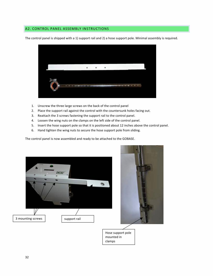
A2. CONTROL PANEL ASSEMBLY INSTRUCTIONS
The control panel is shipped with a 1) support rail and 2) a hose support pole. Minimal assembly is required.
1. Unscrew the three large screws on the back of the control panel 2. Place the support rail against the control with the countersunk holes facing out. 3. Reattach the 3 screws fastening the support rail to the control panel. 4. Loosen the wing nuts on the clamps on the left side of the control panel. 5. Insert the hose support pole so that it is positioned about 12 inches above the control panel. 6. Hand tighten the wing nuts to secure the hose support pole from sliding.
The control panel is now assembled and ready to be attached to the GOBASE.
3 mounting screws support rail
Hose support pole mounted in clamps

33
A3. TROUBLESHOOTING ALARMS AND ERRORS
Solutions to common problems and questions. Please look at the website – www.GOfermentor.com for an updated list of FAQs.
Liner appear to inflate too much ! For small volumes you may want to lower the trip pressure ( PRO-‐>SETUP-‐>PUNCH). While it may look scary, the pressure controller will not let you overpressurize the liner (>25inH2O).
Liner inflation does not seem to move the cap much For large volumes try raising the pressure to 20 inH2O. I cannot press all the liquid out The pressing is very gentle to maximize quality. You
may perhaps get a 3-‐5 liters less than with a conventional press however the time and effort to get this poorer quality “hard press” is not worth it.
I cannot get the drain valve to lock correctly You need to position it in the opening and pull it out towards you. You may need pliers to lock the tabs in. Look at the photos in the manual.
My liner is leaking This is very rare. The only option is to pump out the must to another GOLINER using a must pump. Remember – you must only FILL through the TOP port.
I cannot remove the drain valve to take out the liner Pull the drain valve out so that it is flush against the lower flange. Now use pliers to pop the tabs off.

34
A4. PRO CONTROLLER CONFIGURATION/SETUP
Advanced features of the PRO controller can be set by accessing the MAIN MENU and then SETUP. The SETUP screen provides access to the following parameters:
PUNCH
The PUNCH menu allows the user to set the duration of each punch cycle in seconds. This is how long the controller will pressurize the secondary chamber. During this cycle the BLOWER will turn on until the set pressure is reach and then turn off for the set OFF time. This cycle will continue for the duration of the set punch cycle.
TEMP
The temperature controlled can be tuned if needed. The controller checks the temperature once every cycle time and modulates the solenoid valve. The cycle time can be changed. The alarm limit can be adjusted to avoid nuisance alarms.
Parameter Default setting Punch duration 60 secs Off time/cycle 10 secs Pressure trippoint 20 inH2O
Parameter Default setting P 6000 I 500 D 0 Cycle time (secs) 60 Alarm limits+/-‐ 1.0 C

35
SET TIME
The real time clock can be set from this screen. Enter the correct date and time and then press SET CLK. Time is displayed in 24 hour format. Time is retained on power down by an internal battery.
SET ADDRESS
The PRO controller should be assigned a unique IP address with the user’s network. Consult your system administrator for suitable settings. Enter the new settings and press SET IP to reset the controller.
Parameter Default setting IP Address 192.168.1.5 IP Port 9080 Subnet 255.255.255.0 DNS server 192.168.1.1 SMTP none SMTP Port none
ERASE LOG
This option allows you to erase the HISTORY log.
NOTE: Once erased, the HISTORY log CANNOT be recovered. Be careful.
ERASE TRENDS
This option allows you to erase the temperature TRENDS.
NOTE: Once erased, the TRENDS CANNOT be recovered. Be careful.

36
A5. GOCOOLER ASSEMBLY INSTRUCTIONS
The GOCOOLER is shipped as two components – 1) stainless-‐steel heat exchanger plate and 2) plastic piping with solenoid control valve.
1. Place the stainless heat exchanger plate on a flat surface. The pipe connection fitting should point upwards.
2. Now position the pipe assembly so that it is vertical with the solenoid valve facing away from the heat exchanger plate. Lower the pipe assembly so that it mates with the pipe connection fittings on the stainless heat exchanger.
3. Tighten the two coupling nuts to ensure a leak proof connection.
The GOCOOLER is now assembled and ready to be placed in the GOBASE. The solenoid valve has a cable that must be plugged in to the jack located on the right side on the control panel (PRO only) near the power entry cable.

37
A6. WARRANTY, LIABILITY, AND RETURNS POLICY
The GOfermentor hardware is warranted to be free of defects in material or workmanship for 12 months after delivery to the first purchaser for use, providing that the units have not been misused. Since we have no control over the operation, we cannot guarantee against failure or loss of product in the unit. Our obligations hereunder, at our option, are limited to the replacement, repair or refund of the purchase, and parts which upon examination prove to be defective within the warranty period.
Disposable items, such as liners, are meant for single-‐use. They are warranted against any defects and will be replaced if found to be defective. Damage caused by improper installation or user error is not covered under the warranty. Unused liners may only be returned within 12 months of delivery.
In no circumstances are we liable for any product loss due to the use of our product. The user is cautioned that this is new technology and they agree to accept the risk inherent in using new technology.
RETURNS
• Call or email [email protected] if you have any problems with the GOfermentor. In most cases we can resolve the issue.
• Email [email protected] for a Return Material Authorization (RMA) number before returning any item.
• Put the RMA on the outside of the shipping label.
+++++++++++++++++++++++++++++++++++++++++++++++++++++++++++++++++++++++++++++++++++++++++++++