GNSS Receiver Front-ends I: Signals, Noise And...
40
DANISH GPS CENTER GNSS Receiver Front-ends I: Signals, Noise And Distortions GPS Receiver Technology MM7 Darius Plaušinaitis [email protected] Based on original slides from Ragnar V. Reynisson
Transcript of GNSS Receiver Front-ends I: Signals, Noise And...
DANISH GPS CENTER
GNSS Receiver Front-ends I:Signals, Noise And DistortionsGPS Receiver Technology MM7Darius Plauš[email protected]
Based on original slides from Ragnar V. Reynisson
DANISH GPS CENTERAgenda
• Receiver Basics• Description of electrical signals• Noise• Linearity/Distortion• Receiver Figures of Merit (FoM)• Summary
2008 Danish GPS Center 2
DANISH GPS CENTERReceiver Basics
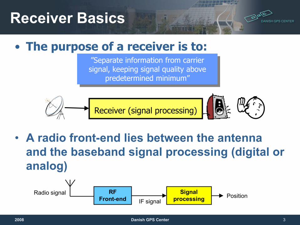
• A radio front-end lies between the antenna and the baseband signal processing (digital or analog)
2008 Danish GPS Center 3
”Separate information from carrier signal, keeping signal quality above
predetermined minimum”
• The purpose of a receiver is to:
RFFront-end
Signal processingIF signal
Radio signal Position
Receiver (signal processing)
DANISH GPS CENTER
Description Of Electrical Signals
2008 4Danish GPS Center
DANISH GPS CENTERSignals
• An RF signal is divided in two distinct parts:– A carrier signal– Modulation (Information)
• The carrier signal is a sine wave which amplitude and frequency depends on the system (standards & regulations)
• The modulation is a time-dependent variation in signal phase, frequency and/or amplitude which carries the actual information content in the signal
2008 Danish GPS Center 5
DANISH GPS CENTER
2008 Danish GPS Center 6
Signals
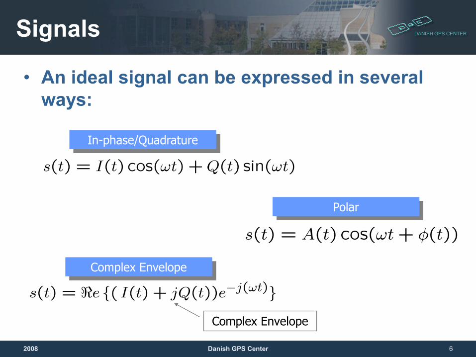
• An ideal signal can be expressed in several ways:
In-phase/Quadrature
Polar
Complex Envelope
Complex Envelope
DANISH GPS CENTERSignals
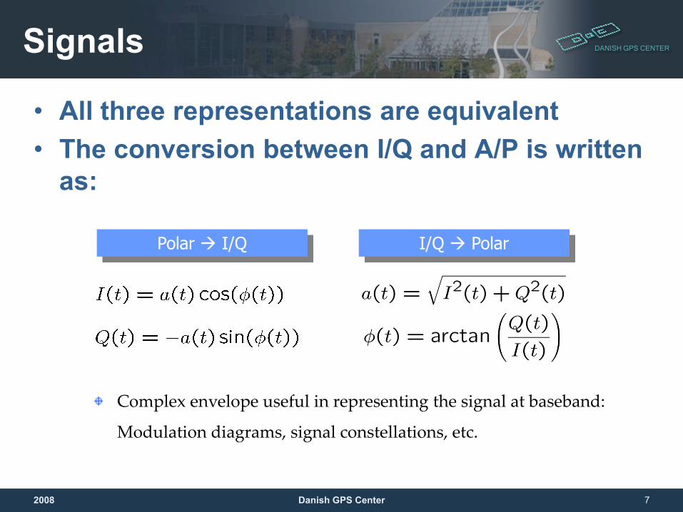
• All three representations are equivalent • The conversion between I/Q and A/P is written
as:
2008 Danish GPS Center 7
Polar I/Q I/Q Polar
Complex envelope useful in representing the signal at baseband:
Modulation diagrams, signal constellations, etc.
DANISH GPS CENTER
2008 Danish GPS Center 8
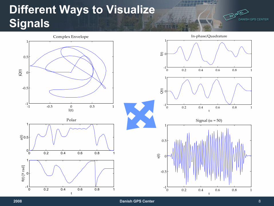
Different Ways to Visualize Signals
0 0.2 0.4 0.6 0.8 1-1
0
1
I(t)
In-phase/Quadrature
0 0.2 0.4 0.6 0.8 1-1
0
1
t
Q(t)
-1 -0.5 0 0.5 1-1
-0.5
0
0.5
1Complex Envelope
I(t)
jQ(t)
0 0.2 0.4 0.6 0.8 10
0.5
1Polar
a(t)
0 0.2 0.4 0.6 0.8 1-1
0
1
t
φ (t)
[π ra
d]
0 0.2 0.4 0.6 0.8 1-1
-0.5
0
0.5
1Signal (ω = 50)
t
s(t)
DANISH GPS CENTER
2008 Danish GPS Center 9
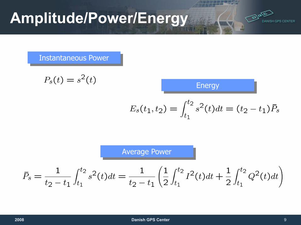
Amplitude/Power/Energy
Instantaneous Power
Average Power
Energy
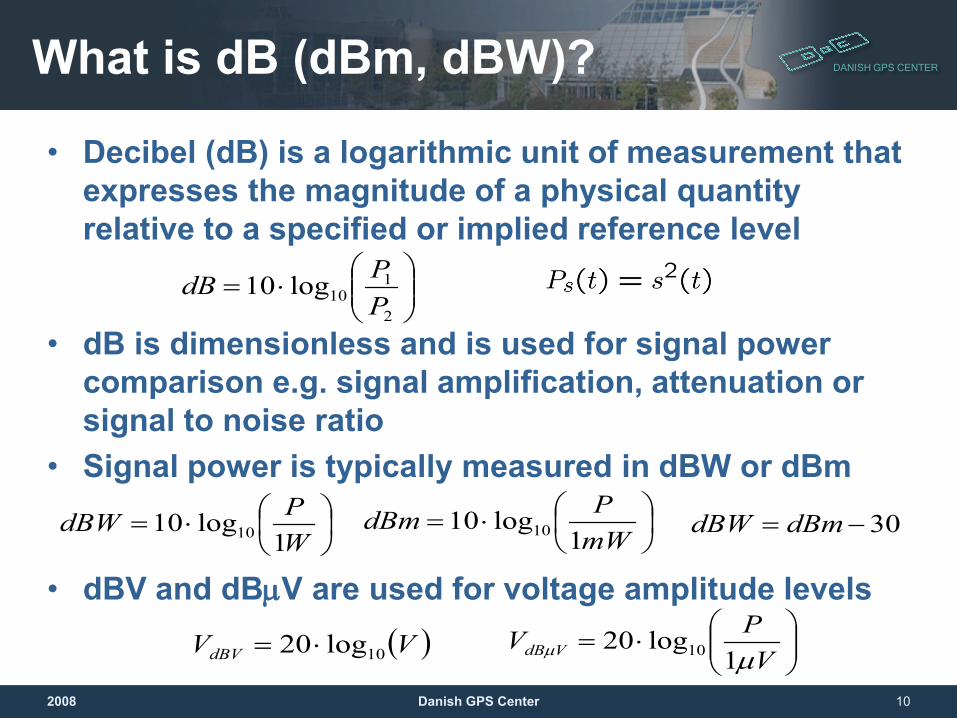
DANISH GPS CENTERWhat is dB (dBm, dBW)?
• Decibel (dB) is a logarithmic unit of measurement that expresses the magnitude of a physical quantity relative to a specified or implied reference level
• dB is dimensionless and is used for signal power comparison e.g. signal amplification, attenuation or signal to noise ratio
• Signal power is typically measured in dBW or dBm
• dBV and dBµV are used for voltage amplitude levels
2008 Danish GPS Center 10
⋅=
2
110log10
PPdB
⋅=
WPdBW
1log10 10
⋅=
mWPdBm
1log10 10 30−= dBmdBW
( )VVdBV 10log20 ⋅=
⋅=
VPV VdB µµ 1
log20 10
DANISH GPS CENTER
Signal Quality
2008 11Danish GPS Center
DANISH GPS CENTERSignal Quality
• Signal Quality is a ”catch-all” term for imperfections in the signal– In digital system SQ is linked to Bit Error Ratio
(BER)– In GNSS SQ is also linked to quality of position
measurements • Several mechanisms affect signal quality:
– Noise– Distortion– Unwanted (interfering) signals
2008 Danish GPS Center 12
DANISH GPS CENTERSignal Quality
• For microwave circuits, noise is predominantly generated inside receiver– Active circuits (noise from semiconductors)– Passive circuits (filters, interconnections – lossy
circuits in general)• Distortion is generated by inherent non-
linearity of active circuits– Non-linear I/V characteristics– Clipping
2008 Danish GPS Center 13
DANISH GPS CENTERSignal Quality
• Strong unwanted signals interfere with signal quality– Drive active circuits (primarily amplifier) into
overload: Blocking– Saturate analogue to digital converts (ADC)– Third-order intermodulation effects can ”mix” two
out-of-band signals onto the wanted frequency band: Impossible to filter out
2008 Danish GPS Center 14
DANISH GPS CENTER
NoiseNoise sources, filtering, SNR
DANISH GPS CENTERPhysical Noise Sources
• Noise can be roughly grouped into:– Externally generated noise
• Man-made noise• Atmospheric noise
– Internally generated noise• Termal noise (one of the biggest noise sources in GNSS)• Resistive/lossy circuits• Semiconductors• Quantization
2008 Danish GPS Center 16
DANISH GPS CENTER
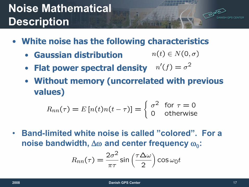
Noise Mathematical Description
• Band-limited white noise is called ”colored”. For a noise bandwidth, ∆ω and center frequency ω0:
2008 Danish GPS Center 17
• White noise has the following characteristics
• Gaussian distribution • Flat power spectral density• Without memory (uncorrelated with previous
values)
DANISH GPS CENTER
2008 Danish GPS Center 18
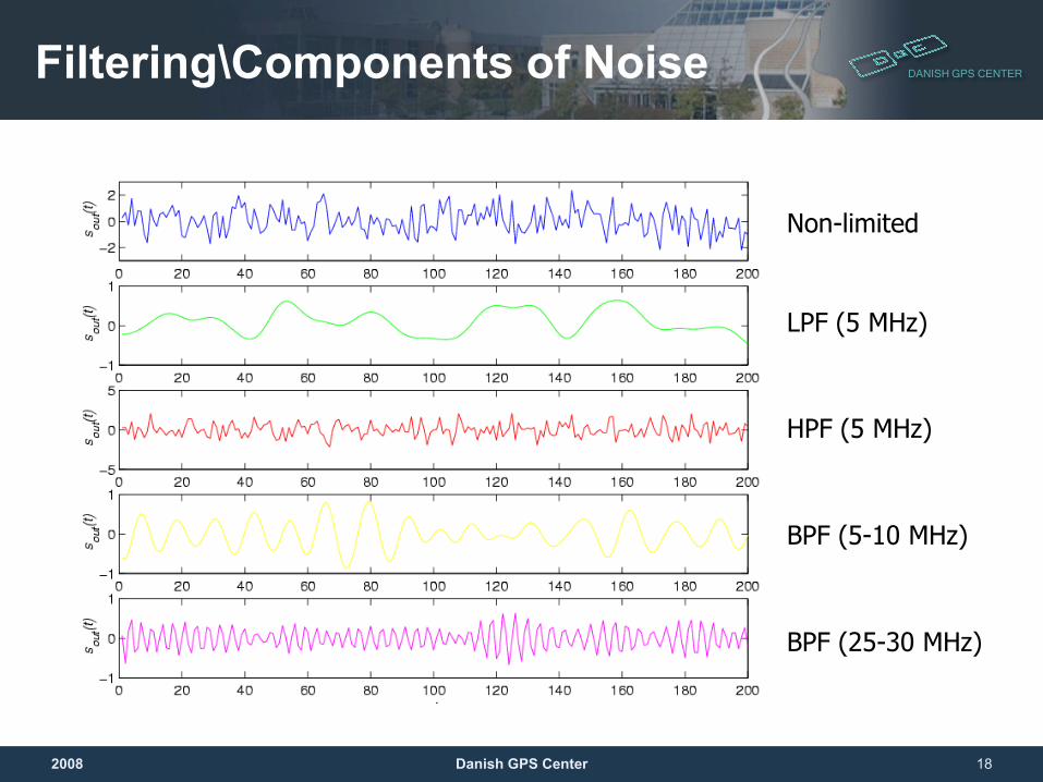
Filtering\Components of Noise
Non-limited
LPF (5 MHz)
HPF (5 MHz)
BPF (5-10 MHz)
BPF (25-30 MHz)
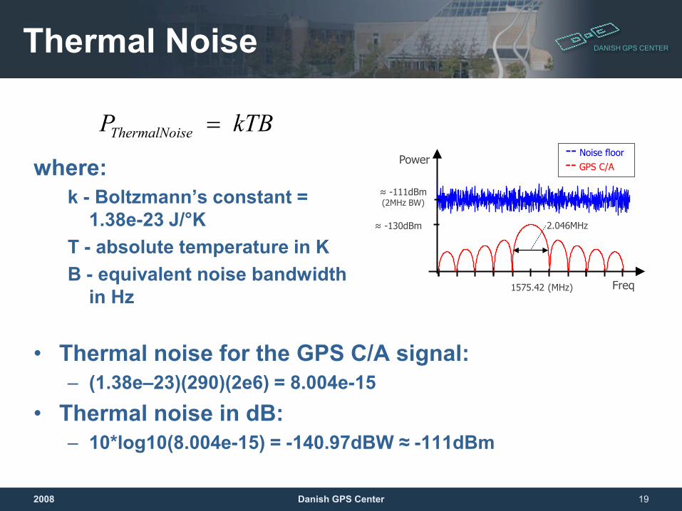
DANISH GPS CENTERThermal Noise
where:k - Boltzmann’s constant =
1.38e-23 J/°KT - absolute temperature in KB - equivalent noise bandwidth
in Hz
• Thermal noise for the GPS C/A signal:– (1.38e–23)(290)(2e6) = 8.004e-15
• Thermal noise in dB:– 10*log10(8.004e-15) = -140.97dBW ≈ -111dBm
2008 Danish GPS Center 19
2.046MHz≈ -130dBm
1575.42 (MHz)
-- GPS C/A
Freq
Power
≈ -111dBm(2MHz BW)
-- Noise floor
kTB P seThermalNoi =
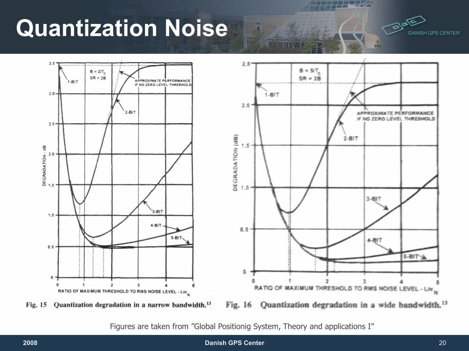
DANISH GPS CENTERQuantization Noise
2008 Danish GPS Center 20
Figures are taken from ”Global Positionig System, Theory and applications I”
DANISH GPS CENTERSignal to Noise ratio (SNR)
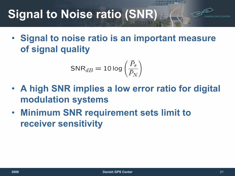
• Signal to noise ratio is an important measure of signal quality
• A high SNR implies a low error ratio for digital modulation systems
• Minimum SNR requirement sets limit to receiver sensitivity
2008 Danish GPS Center 21
DANISH GPS CENTER
Signal Distortions
DANISH GPS CENTERDistortion
• While noise is critical for weak signals, distortion sets the upper limit on receiver performance
• This is because often strong (wanted and/or interfering) signals cause distortions, but there are also other kinds of distortions
2008 Danish GPS Center 23
DANISH GPS CENTERDistortion
• Different distortion mechanisms include:– Nonlinear transfer functions – Clipping (signal amplitude exceeds hardware
limits)• Distortions can occur also due to other
(interfering) signals– Powerful, unwanted signals can block receiver by
driving non-linear circuits into compression– An intermodulation product of two powerful
unwanted signals can cause interference in the signal band impossible to filter out
2008 Danish GPS Center 24
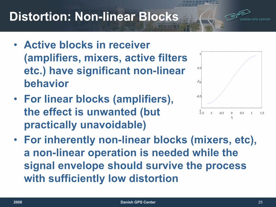
DANISH GPS CENTERDistortion: Non-linear Blocks
• Active blocks in receiver (amplifiers, mixers, active filters etc.) have significant non-linear behavior
• For linear blocks (amplifiers), the effect is unwanted (but practically unavoidable)
2008 Danish GPS Center 25
-1.5 -1 -0.5 0 0.5 1 1.5-1
-0.5
0
0.5
1
si
s o
• For inherently non-linear blocks (mixers, etc), a non-linear operation is needed while the signal envelope should survive the process with sufficiently low distortion
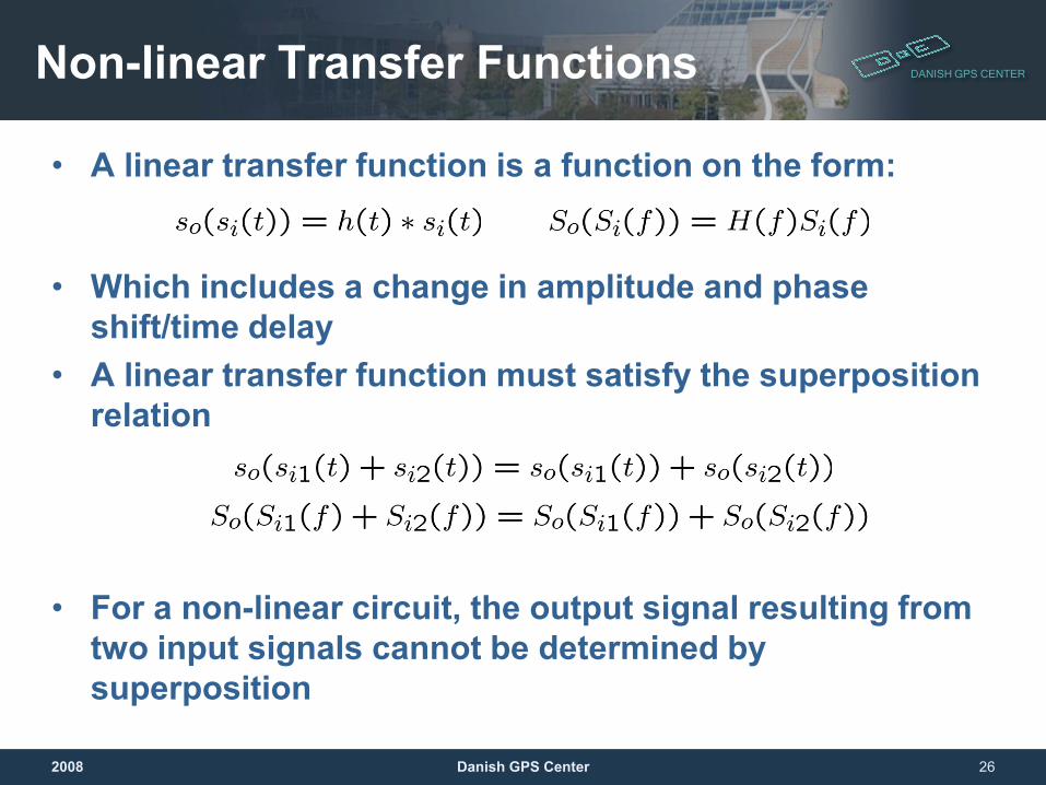
DANISH GPS CENTERNon-linear Transfer Functions
• A linear transfer function is a function on the form:
• Which includes a change in amplitude and phase shift/time delay
• A linear transfer function must satisfy the superposition relation
• For a non-linear circuit, the output signal resulting from two input signals cannot be determined by superposition
2008 Danish GPS Center 26
DANISH GPS CENTER
2008 Danish GPS Center 27
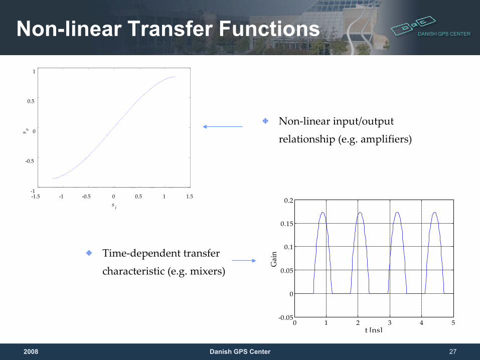
Non-linear Transfer Functions
Non-linear input/output
relationship (e.g. amplifiers)
-1.5 -1 -0.5 0 0.5 1 1.5-1
-0.5
0
0.5
1
s i
s o
0 1 2 3 4 5-0.05
0
0.05
0.1
0.15
0.2
t [ns]
Gai
nTime-dependent transfer
characteristic (e.g. mixers)
DANISH GPS CENTER
2008 Danish GPS Center 28
Non-linear Effects Are…
• Complex to model simple models for hand calculations are rough guesses at best
• Difficult to calculate analytically For most RF receivers, the non-linear behavior of the circuits is found via simulations
• On a system level, distortion effects are hard to estimate without simulations
DANISH GPS CENTER
2008 Danish GPS Center 29
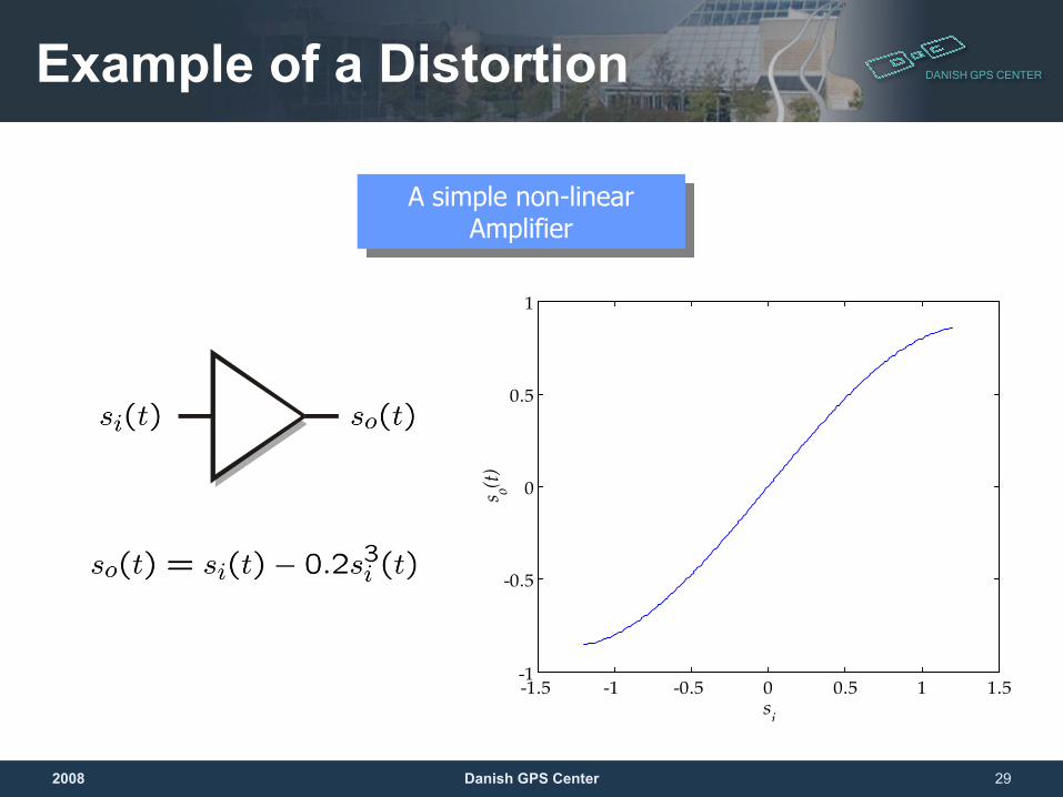
Example of a Distortion
-1.5 -1 -0.5 0 0.5 1 1.5-1
-0.5
0
0.5
1
si
s o(t)
A simple non-linear Amplifier
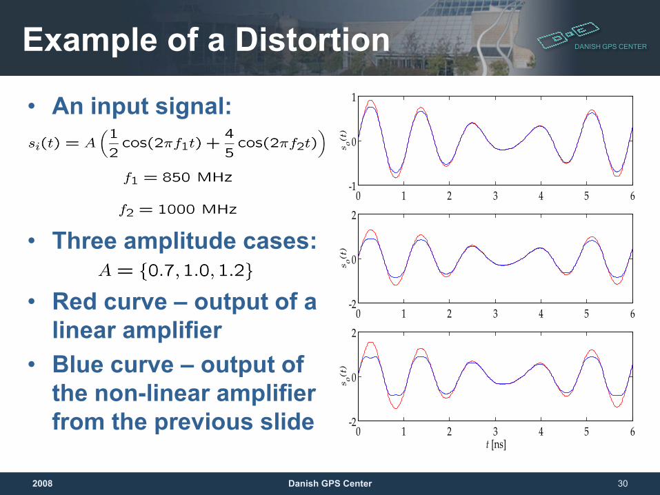
DANISH GPS CENTERExample of a Distortion
• An input signal:
• Three amplitude cases:
• Red curve – output of a linear amplifier
• Blue curve – output of the non-linear amplifier from the previous slide
2008 Danish GPS Center 30
0 1 2 3 4 5 6-1
0
1
so(
t)
0 1 2 3 4 5 6-2
0
2
so(
t)
0 1 2 3 4 5 6-2
0
2
t [ns]
so(
t)
DANISH GPS CENTER
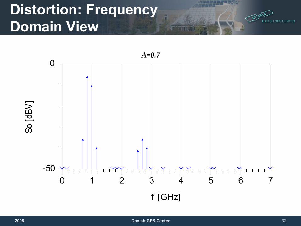
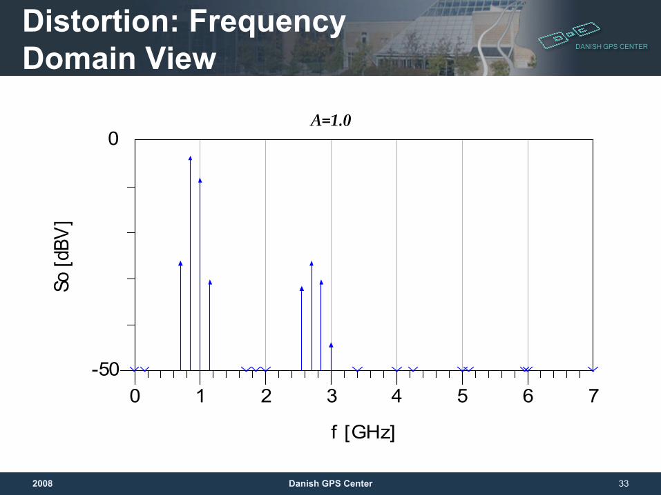
Distortion: Frequency Domain View• For RF circuits, time domain measurements can be
hard to perform or evaluate• For transmitters, time-domain tests involving
modulated signals is possible• Receiver distortion analysis is most often performed
in the frequency domain• Next slide: A look at the output of the amplifier from
the previous example in the frequency domain• The two largest tones (arrows) in the graphs are the
fundamental frequencies (850 MHz and 1 GHz). The remainder of the spectrum is due to distortion.
2008 Danish GPS Center 31
DANISH GPS CENTER
2008 Danish GPS Center 32
Distortion: Frequency Domain View
A=0.7
1 2 3 4 5 60 7-50
0
f [GHz]
So [d
BV]
DANISH GPS CENTER
2008 Danish GPS Center 33
Distortion: Frequency Domain View
1 2 3 4 5 60 7-50
0
f [GHz]
So [d
BV]
A=1.0
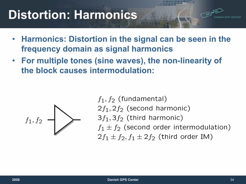
DANISH GPS CENTERDistortion: Harmonics
• Harmonics: Distortion in the signal can be seen in the frequency domain as signal harmonics
• For multiple tones (sine waves), the non-linearity of the block causes intermodulation:
2008 Danish GPS Center 34
DANISH GPS CENTER
Receiver Figures-of-Merit
DANISH GPS CENTERReceiver Figures-of-Merit
• Gain• Sensitivity/Noise Figure• Intercept points (2nd and 3rd order)• Dynamic Range
2008 Danish GPS Center 36
DANISH GPS CENTERGain
• Gain is a measure of power or amplitude increase/decrease
• For RF circuits power gain is most frequently used , as voltage levels can be hard to define due to standing waves and reflected signals
• For integrated circuits, voltage gain is sometimes used at RF and most often at baseband
2008 Danish GPS Center 37
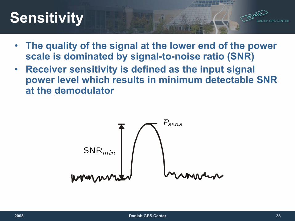
DANISH GPS CENTERSensitivity
• The quality of the signal at the lower end of the power scale is dominated by signal-to-noise ratio (SNR)
• Receiver sensitivity is defined as the input signal power level which results in minimum detectable SNR at the demodulator
2008 Danish GPS Center 38
DANISH GPS CENTERDynamic Range
• The dynamic range of the receiver is the range of input power levels that the receiver can be used for without noise or distortion corrupting the signal
2008 Danish GPS Center 39
DANISH GPS CENTERSummary
• Radio receivers must deliver a received signal to the signal processor while adding a minimum of noise and distortion
• Noise can “burry” weak signals• Distortion change received signals and/or create
unwanted additional signals• Receiver/components figures of merit:
• Gain• Intercept point• Sensitivity• Dynamic range• Noise figure
2008 Danish GPS Center 40