
GNSS Absolute Antenna Calibration at the National Geodetic Survey
42
GNSS Absolute Antenna Calibration at the National Geodetic Survey Andria Bilich & Gerald Mader Geosciences Research Division National Geodetic Survey
-
Upload
uma-sanford -
Category
Documents
-
view
25 -
download
0
description
GNSS Absolute Antenna Calibration at the National Geodetic Survey. Andria Bilich & Gerald Mader Geosciences Research Division National Geodetic Survey. The Antcal Team. Frank Marion Jaya Neti Giovanni Sella Bruce Tran Jarir Saleh Mark Schenewerk. Steven Breidenbach Hong Chen - PowerPoint PPT Presentation
Transcript of GNSS Absolute Antenna Calibration at the National Geodetic Survey

GNSS Absolute Antenna Calibration at the
National Geodetic Survey
Andria Bilich & Gerald MaderGeosciences Research Division
National Geodetic Survey
The Antcal Team
Steven BreidenbachHong ChenKendall FancherCharles GeogheganDavid GietkaHeeyul HanDennis Lokken
Frank MarionJaya NetiGiovanni SellaBruce TranJarir SalehMark Schenewerk
2

Talk Outline
• What is antenna calibration?• Relative versus absolute• Motivation for NGS absolute facility• NGS methods and observation models• Example results• Tools for the customer
3
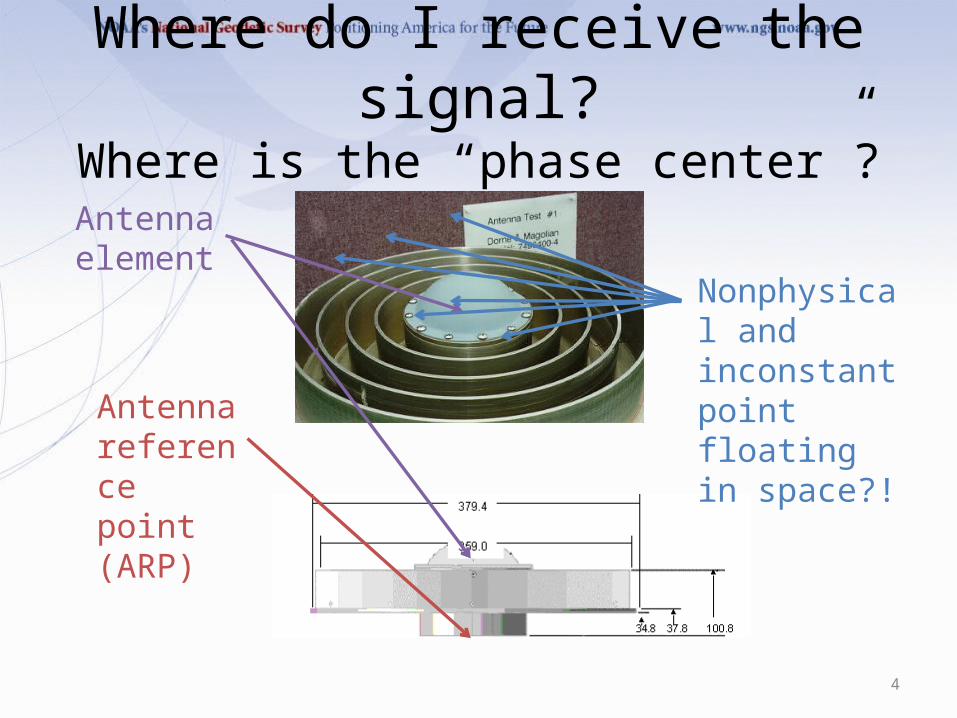
Where do I receive the signal?Where is the “phase center”?
Antenna reference point (ARP)
Antenna element
Nonphysical and inconstant point floating in space?!
4
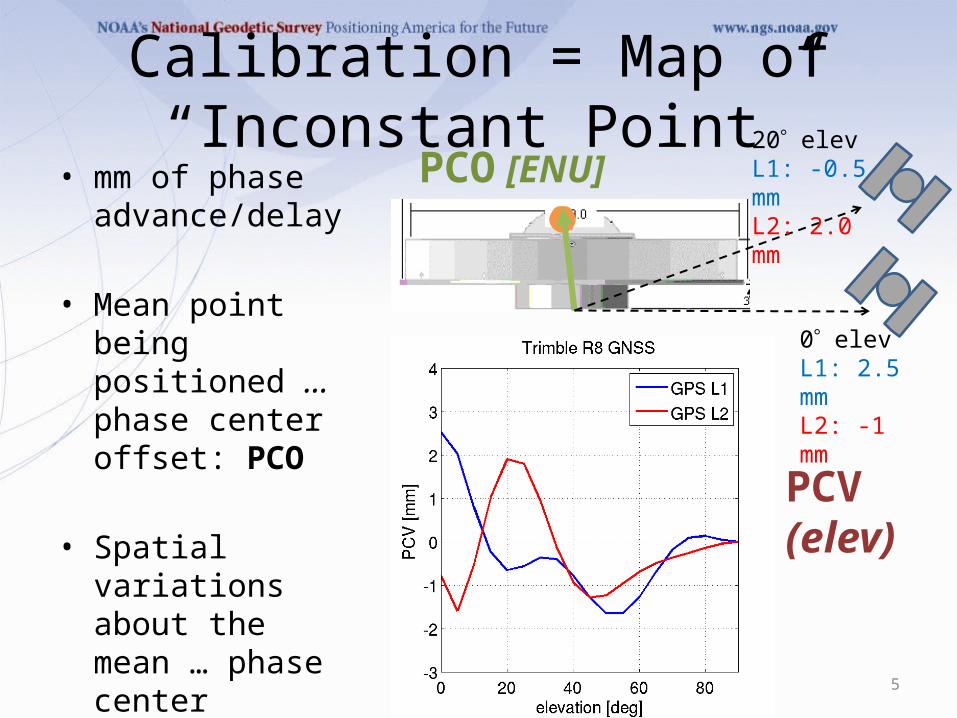
Calibration = Map of “Inconstant Point”
• mm of phase advance/delay
• Mean point being positioned … phase center offset: PCO
• Spatial variations about the mean … phase center variations: PCV
5
0 elevL1: 2.5 mmL2: -1 mm
20 elevL1: -0.5 mmL2: 2.0 mm
PCO [ENU]
PCV(elev)

PCV Azimuthal Dependence
6

Why Do I Need Calibrations?
• Antenna introduces several mm-cm of phase advance/delay -> range errors
• Input to most GNSS data processing software
• Omitting calibrations can cause problems:– Long baselines– Combining multiple antenna models– Height errors
7

Relative vs. AbsoluteRelative Absolute
Calibration values Relative to a reference antenna (AOA D/M_T)
Independent of reference antenna
Method Stationary antennas Test antenna moves
Advantages Straightforward math Sample full hemisphere and low elevation angles
Limitations Cannot sample full pattern Requires robot and rigorous accounting of angles & rotations
8
Do not combine relative and absolute calibrations!

Why Go to Absolute?
• Better/fuller description of phase behavior– 0-10 elevation coverage– Azimuthal variations– Multipath removed/negated
• The way of the future– International GNSS Service (IGS) standard– Used in OPUS– Used in CORS multiyear [IGS08 epoch 2005.0 and
NAD 83(2011) epoch 2010.0]
9

Who Does Absolute Calibrations?Geo++ TU Darmstadt
Method Field with GNSS signals Anechoic chamber with pure sine waves
Robot 3-axis, PCO held fixed 2-axis, PCO moves
Institution For-profit University
10
Up and coming: Australia, China

NGS Absolute CalibrationMotivations and Goals
Serve high precision needs of U.S. surveying and geodesy communities
• Multi-frequency, multi-GNSS calibrations• 2-D (elevation, azimuth) phase center patterns• Free calibration service w/ quick turn-around• Calibration values publicly distributed via Internet• Compatibility with IGS ANTEX values
11

Compatibility with IGS
12
• IGS ANTEX as “truth”• IGS Antenna
Working Group acceptable deviations– < 1 mm for high
elevations (>= 10)– < 2 mm for low
elevations (0-10)
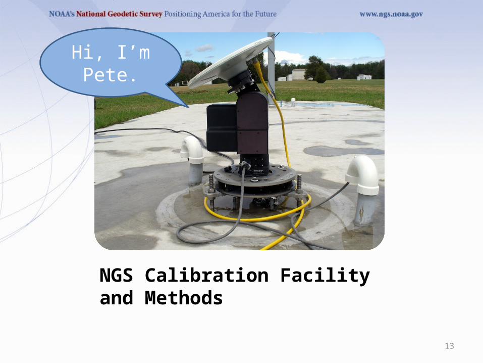
NGS Calibration Facility and Methods
13
Hi, I’m Pete.
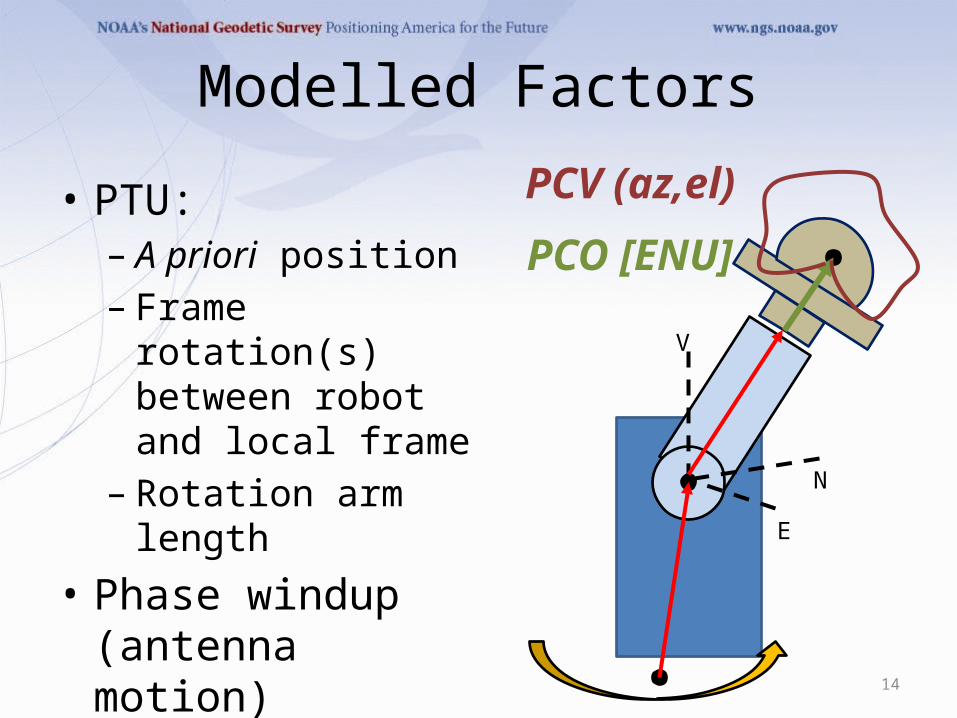
Modelled Factors
E
N
V
PCO [ENU]
PCV (az,el)• PTU:– A priori position– Frame rotation(s)
between robot and local frame
– Rotation arm length• Phase windup
(antenna motion)• GPS/PC clock offsets
14
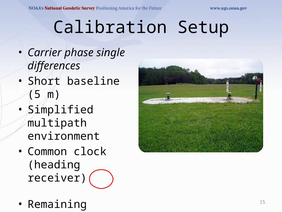
Calibration Setup• Carrier phase single
differences• Short baseline (5 m)• Simplified multipath
environment• Common clock (heading
receiver)
• Remaining factors = phase centers (ref, test), differential multipath, hardware bias
15
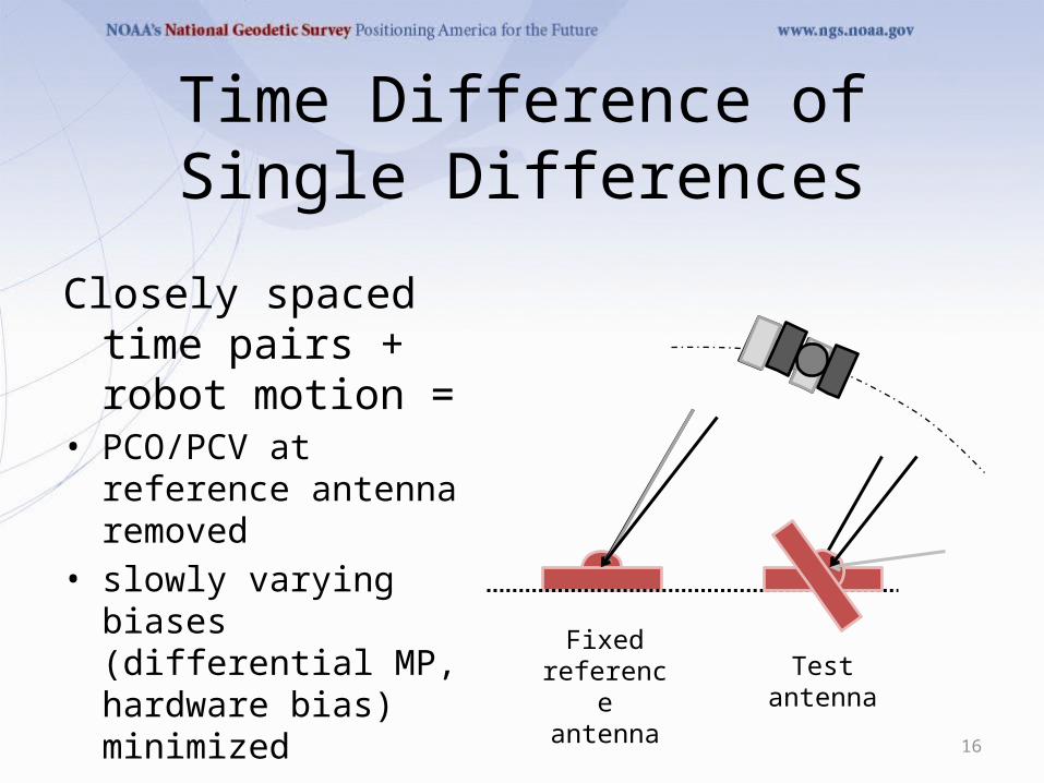
Time Difference of Single Differences
Closely spaced time pairs + robot motion =
• PCO/PCV at reference antenna removed
• slowly varying biases (differential MP, hardware bias) minimized
16
Fixed reference antenna
Test antenna
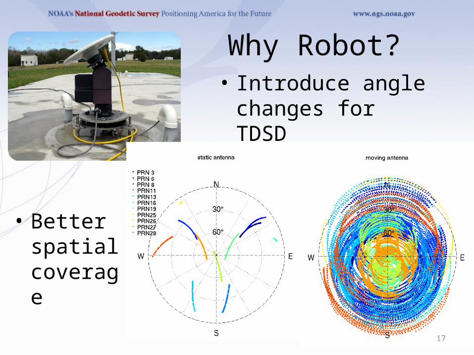
Why Robot?• Introduce angle
changes for TDSD
• Better spatial coverage
17

NGS Robot Limitations
• 2-axis = cannot sample full angular range
• Motor box limits tilt
• Tilt introduces change in antenna height above ground … multipath?
18
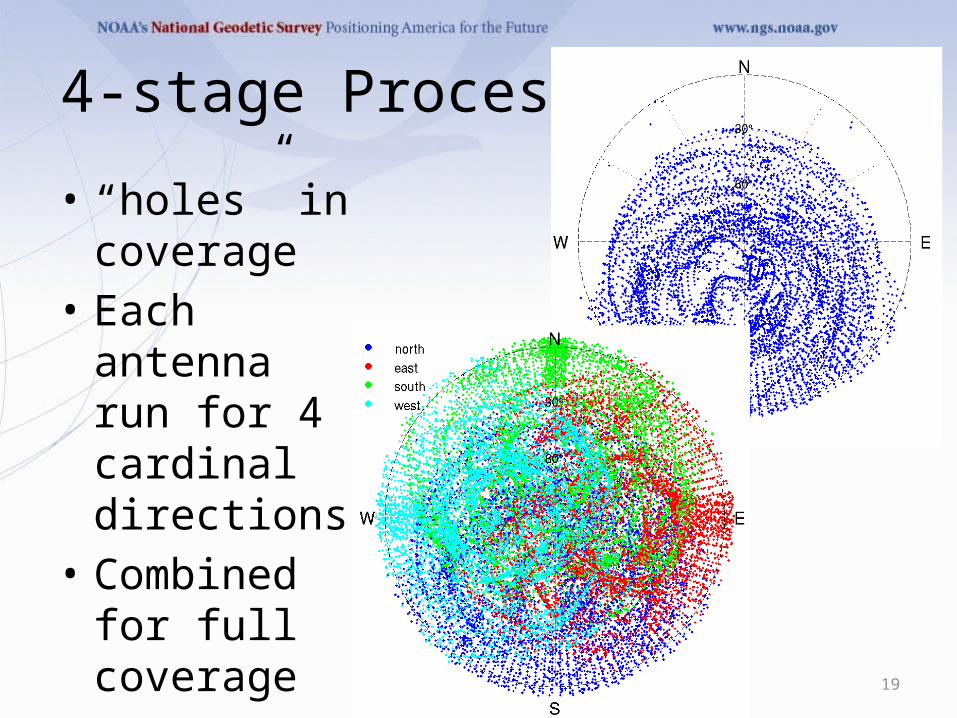
4-stage Process
• “holes” in coverage
• Each antenna run for 4 cardinal directions
• Combined for full coverage
19

Estimation strategy
Form / Solve Normal Equations
PCO (east, north, up components) PCV (elevation and azimuth angle)
Time Difference of Single Difference Phase Pairs
Single Difference Phase
Cycle slip editing Phase windup PTU tilt arm
Calculation of angles
Angles in local frame Angles in antenna frame
Pre-Edit Phase
Geometric range Satellite XYZ/velocity calcs (for windup)
20
NorthEastSouthWest

So Many Variables!
• Elevation cutoffs– Local frame– Antenna frame
• Order/degree of harmonics• Data spacing/distribution• Robot motion scenario (delta pan)
21

NGS Calibration Results
22
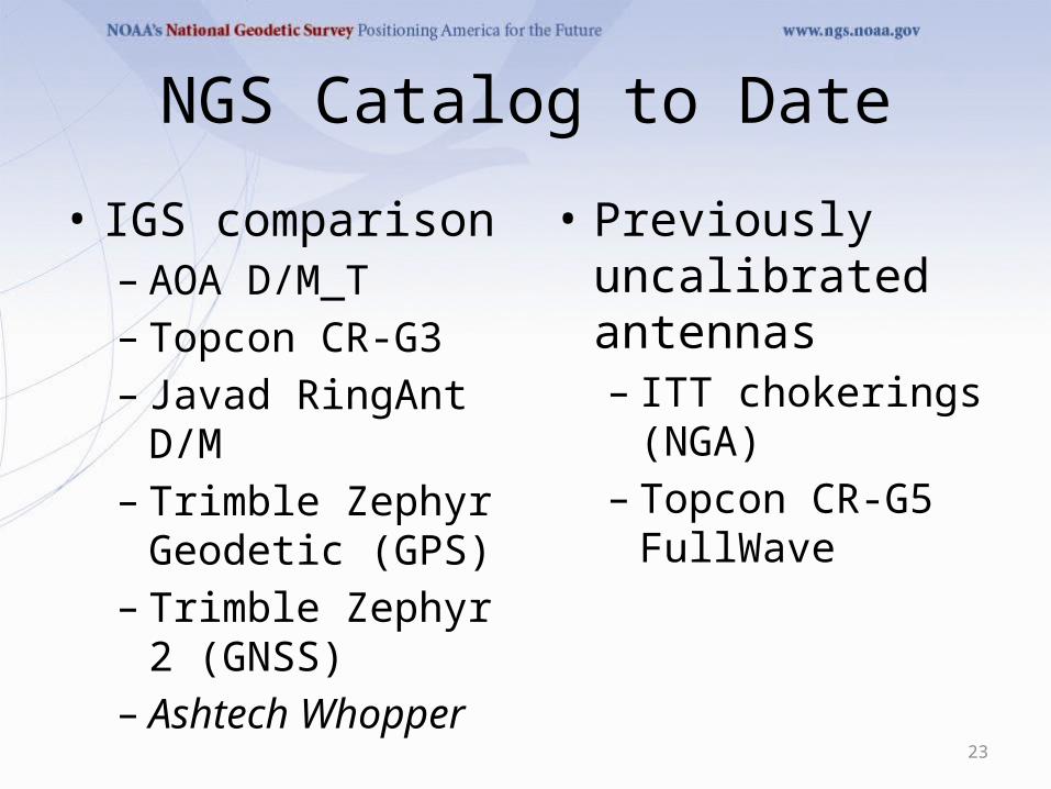
NGS Catalog to Date
• IGS comparison– AOA D/M_T– Topcon CR-G3– Javad RingAnt D/M– Trimble Zephyr
Geodetic (GPS)– Trimble Zephyr 2
(GNSS)– Ashtech Whopper
23
• Previously uncalibrated antennas– ITT chokerings (NGA)– Topcon CR-G5
FullWave

Allen Osborne chokering rev T AOAD/M_T
24
s/n 149
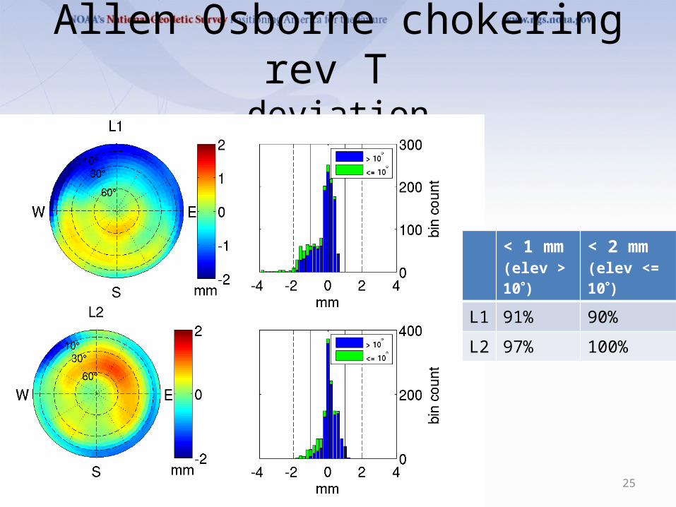
Allen Osborne chokering rev T deviation
25
< 1 mm(elev > 10)
< 2 mm(elev <= 10)
L1 91% 90%
L2 97% 100%

Javad RingAnt-DMJAVRINGANT_DM
26
s/n 00553
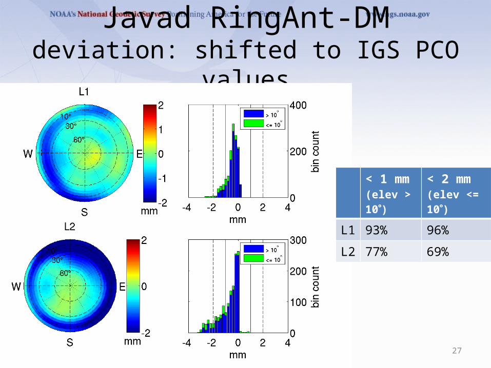
Javad RingAnt-DMdeviation: shifted to IGS PCO values
27
< 1 mm(elev > 10)
< 2 mm(elev <= 10)
L1 93% 96%
L2 77% 69%

Javad RingAnt-DMdeviation: keeping NGS PCO values
28
< 1 mm(elev > 10)
< 2 mm(elev <= 10)
L1 100% 100%
L2 90% 92%

Trimble Zephyr 2TRM55971.00
29
s/n 30255823
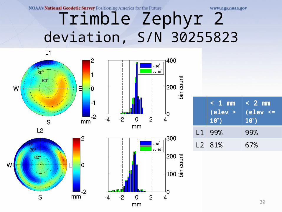
Trimble Zephyr 2deviation, S/N 30255823
30
< 1 mm(elev > 10)
< 2 mm(elev <= 10)
L1 99% 99%
L2 81% 67%

Trimble Zephyr 2deviation, S/N 30212854
31
< 1 mm(elev > 10)
< 2 mm(elev <= 10)
L1 98% 97%
L2 71% 67%
Different serial number, different deviations

Trimble Zephyr 2L1 Type Mean
32
test 1: 0.90 0.40 66.69test 2: 0.58 0.16 67.57test 3: 0.48 0.40 65.99test 4: 0.73 -0.42 65.96test 5: 0.94 -0.19 66.26test 6: 0.61 -0.01 65.88
std : 0.18 0.33 0.65
NGS MEAN: 0.71 0.06 66.39IGS MEAN: 1.29 -0.19 66.73Diff : 0.58 -0.25 0.34

Trimble Zephyr 2L2 Type Mean
33
test 1: 0.61 1.50 58.32test 2: 0.20 1.24 58.65test 3: 0.12 0.71 57.84test 4: -0.41 -0.16 57.93test 5: -0.16 0.18 58.63test 6: -0.25 0.80 57.63
std : 0.37 0.62 0.43
NGS MEAN: 0.02 0.71 58.17IGS MEAN: 0.38 0.61 57.69Diff 0.36 -0.10 -0.48

Trimble Zephyr 2L1 Type Mean: NGS vs IGS
34

Trimble Zephyr 2L2 Type Mean: NGS vs IGS
35

Outstanding Questions
• Source of histogram bias and skew towards negative residuals
• Misfit at < 20• Type mean– Common PCO or individual PCOs?– Statistics?– Number of antennas required?
36
Development Next Steps
• IGS AWG approval• Permanent piers• GLONASS• More automated data retrieval/processing
37
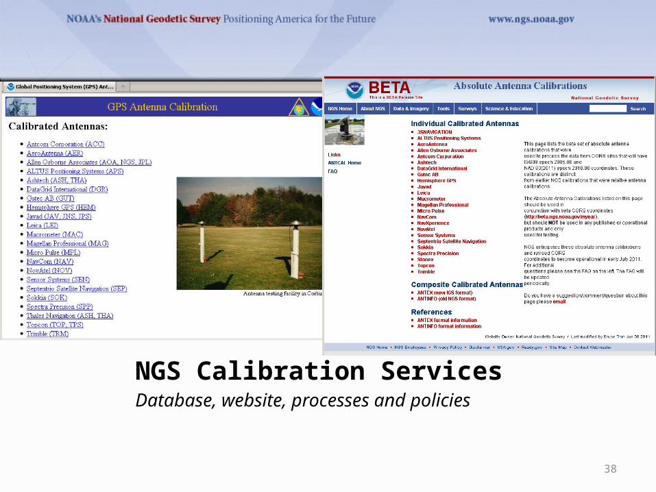
NGS Calibration ServicesDatabase, website, processes and policies
38

New Website
• Revamped along with database
• Photo & drawing mouseovers for easy ID
• ANTINFO and ANTEX formats 39

Formal Policy Document
• Approved by ESC• Purpose/Goal– Clear expectations– Make our jobs easier
• Doc contents– Calibration process and stages– Eligibility for calibration– Rights and responsibilities (both NGS and antenna
provider)40
Revisions expected• with manufacturer input • after calibration tracking system comes online

Antenna Intake
• Request calibration via web form
• Tracking system • Customer
notification emails
41

Conclusions and Outlook
• Good agreement with IGS type means... but needs improvement
• Pending approval from IGS Antenna Working Group
• Soon to be “open for business”• For more information– http://www.ngs.noaa.gov/ANTCAL– Email [email protected] or


