GNSDO(tm) User Manual - Jackson Labs Use an approved Antenna Lightning Protector ... a wide-range...
88
Low Noise Rubidium GNSDO (tm) User Manual Document: 80200526 Version: 1.3 Date: 28 August, 2015
Transcript of GNSDO(tm) User Manual - Jackson Labs Use an approved Antenna Lightning Protector ... a wide-range...
Low Noise Rubidium
GNSDO(tm) UserManual
Document: 80200526Version: 1.3Date: 28 August, 2015
Low Noise Rubidium GNSDO(tm) User Manual
Copyright © 2015, Jackson Labs Technologies, Inc.
Low Noise Rubidium GPSDO User Manual
1 Introduction . . . . . . . . . . . . . . . . . . . . . . . . . . . . . 1
1.1 Overview . . . . . . . . . . . . . . . . . . . . . . . . . . . . . . . 11.2 Operating Principles . . . . . . . . . . . . . . . . . . . . . . . . . . . 31.3 General Safety Precautions . . . . . . . . . . . . . . . . . . . . . . . . 4
1.3.1 Use an approved Antenna Lightning Protector . . . . . . . . . . . . . . 41.3.2 Grounding . . . . . . . . . . . . . . . . . . . . . . . . . . . . 41.3.3 Power Connections. . . . . . . . . . . . . . . . . . . . . . . . . 41.3.4 Environmental Conditions . . . . . . . . . . . . . . . . . . . . . . 4
2 GNSDO Quick-Start Instructions . . . . . . . . . . . . . . . . . 5
2.1 Ordering Options . . . . . . . . . . . . . . . . . . . . . . . . . . . . 52.2 Powering Up the Unit . . . . . . . . . . . . . . . . . . . . . . . . . . 52.3 Block Diagram . . . . . . . . . . . . . . . . . . . . . . . . . . . . . 62.4 Mechanical Drawing . . . . . . . . . . . . . . . . . . . . . . . . . . . 72.5 Operating the unit . . . . . . . . . . . . . . . . . . . . . . . . . . . . 82.6 Accessing internal connections . . . . . . . . . . . . . . . . . . . . . . 92.7 Major Connections . . . . . . . . . . . . . . . . . . . . . . . . . . . 9
2.7.1 Power Harness Pinning . . . . . . . . . . . . . . . . . . . . . . .102.7.2 RS-422 Connector JP2 . . . . . . . . . . . . . . . . . . . . . . .122.7.3 Harness Connectors J1 and J3 . . . . . . . . . . . . . . . . . . . .132.7.4 Connecting External Loads and Sources . . . . . . . . . . . . . . . .13
2.7.4.1 5MHz Internal CMOS output . . . . . . . . . . . . . . . . . .132.7.4.2 LOCK_OK Output . . . . . . . . . . . . . . . . . . . . . .132.7.4.3 10MHz Sine Wave Outputs . . . . . . . . . . . . . . . . . .132.7.4.4 CMOS 1PPS Outputs . . . . . . . . . . . . . . . . . . . .142.7.4.5 RS-232 Interfaces . . . . . . . . . . . . . . . . . . . . . .142.7.4.6 RS-422 Interface . . . . . . . . . . . . . . . . . . . . . .142.7.4.7 1PPS CMOS/TTL Input . . . . . . . . . . . . . . . . . . . .15
2.7.5 Connecting the GPS/Glonass Antenna . . . . . . . . . . . . . . . . .152.7.6 Selecting GNSS Systems . . . . . . . . . . . . . . . . . . . . . .152.7.7 Connecting an LCD Display . . . . . . . . . . . . . . . . . . . . .16
2.7.7.1 LCD Key. . . . . . . . . . . . . . . . . . . . . . . . . .172.7.7.2 LCD Display Pages . . . . . . . . . . . . . . . . . . . . .18
2.8 Loop parameter adjustment . . . . . . . . . . . . . . . . . . . . . . . .222.9 Performance graphs . . . . . . . . . . . . . . . . . . . . . . . . . . .24
3 GNSDO SCPI-Control Quick Start Instructions . . . . . . . . .33
3.1 Introduction . . . . . . . . . . . . . . . . . . . . . . . . . . . . . .333.2 General SCPI Commands . . . . . . . . . . . . . . . . . . . . . . . .34
3.2.1 *IDN? . . . . . . . . . . . . . . . . . . . . . . . . . . . . . .343.2.2 HELP?. . . . . . . . . . . . . . . . . . . . . . . . . . . . . .34
3.3 GPS Subsystem . . . . . . . . . . . . . . . . . . . . . . . . . . . .343.3.1 GPS:SATellite:TRAcking:COUNt? . . . . . . . . . . . . . . . . . . .353.3.2 GPS:SATellite:VISible:COUNt? . . . . . . . . . . . . . . . . . . . .353.3.3 NMEA Support . . . . . . . . . . . . . . . . . . . . . . . . . .353.3.4 GPS:PORT <RS232 | USB> . . . . . . . . . . . . . . . . . . . .363.3.5 GPS:PORT? . . . . . . . . . . . . . . . . . . . . . . . . . . .363.3.6 GPS:GPGGA . . . . . . . . . . . . . . . . . . . . . . . . . . .363.3.7 GPS:GGASTat . . . . . . . . . . . . . . . . . . . . . . . . . .363.3.8 GPS:GPRMC . . . . . . . . . . . . . . . . . . . . . . . . . . .36
© 2015 Jackson Labs Technologies, Inc. i
Low Noise Rubidium GPSDO User Manual
3.3.9 GPS:GPZDA . . . . . . . . . . . . . . . . . . . . . . . . . . . 373.3.10GPS:GPGSV. . . . . . . . . . . . . . . . . . . . . . . . . . . 373.3.11GPS:PASHR . . . . . . . . . . . . . . . . . . . . . . . . . . . 373.3.12GPS:XYZSPeed . . . . . . . . . . . . . . . . . . . . . . . . . 383.3.13GPS:DYNAMic:MODE . . . . . . . . . . . . . . . . . . . . . . . 393.3.14GPS:DYNAMic:MODE 8 (Automatic Dynamic Mode) . . . . . . . . . . . 403.3.15GPS:DYNAMic:STATe? . . . . . . . . . . . . . . . . . . . . . . 413.3.16GPS:REFerence:ADELay <float> <s | ns > [-32767ns,32767ns]. . . . . . . 413.3.17GPS:REFerence:PULse:SAWtooth? . . . . . . . . . . . . . . . . . 423.3.18GPS:RESET ONCE . . . . . . . . . . . . . . . . . . . . . . . . 423.3.19GPS:TMODe <ON | OFF | RSTSURV> . . . . . . . . . . . . . . . . 423.3.20GPS:SURVey ONCE . . . . . . . . . . . . . . . . . . . . . . . 433.3.21GPS:SURVey:DURation <sec> . . . . . . . . . . . . . . . . . . . 433.3.22GPS:SURVey:VARiance <mm^2> . . . . . . . . . . . . . . . . . . 433.3.23GPS:HOLD:POSition <cm, cm, cm> . . . . . . . . . . . . . . . . . 433.3.24GPS:SURVey:STATus? . . . . . . . . . . . . . . . . . . . . . . 433.3.25GPS:INITial:DATE <yyyy,mm,dd> . . . . . . . . . . . . . . . . . . 433.3.26GPS:INITial:TIME <hour,min,sec> . . . . . . . . . . . . . . . . . . 443.3.27GPS:SYST:SELect [GPS | SBAS | QZSS | GLO | BD] . . . . . . . . . . . 443.3.28GPS:JAMlevel? . . . . . . . . . . . . . . . . . . . . . . . . . . 443.3.29GPS:FWver? . . . . . . . . . . . . . . . . . . . . . . . . . . . 443.3.30GPS?. . . . . . . . . . . . . . . . . . . . . . . . . . . . . . 44
3.4 GYRO SUBSYSTEM . . . . . . . . . . . . . . . . . . . . . . . . . . 443.4.1 GYRO:MODE <ON | OFF> . . . . . . . . . . . . . . . . . . . . . 453.4.2 GYRO:TRACE <int> [0,255]. . . . . . . . . . . . . . . . . . . . . 453.4.3 GYRO:PORT <RS232 | USB> . . . . . . . . . . . . . . . . . . . 453.4.4 GYRO:PORT? . . . . . . . . . . . . . . . . . . . . . . . . . . 453.4.5 GYRO:CAL <float,float,float,float,float,float>. . . . . . . . . . . . . . . 453.4.6 GYRO:CAL:COMPUTE. . . . . . . . . . . . . . . . . . . . . . . 453.4.7 GYRO:SENS and GPS:CAL:RESET . . . . . . . . . . . . . . . . . 463.4.8 GYRO:GLOAD? . . . . . . . . . . . . . . . . . . . . . . . . . 46
3.5 PTIME Subsystem . . . . . . . . . . . . . . . . . . . . . . . . . . . 463.5.1 PTIMe:DATE? . . . . . . . . . . . . . . . . . . . . . . . . . . 463.5.2 PTIMe:TIME? . . . . . . . . . . . . . . . . . . . . . . . . . . 473.5.3 PTIMe:TIME:STRing? . . . . . . . . . . . . . . . . . . . . . . . 473.5.4 PTIMe:TINTerval? . . . . . . . . . . . . . . . . . . . . . . . . . 473.5.5 PTIME:OUTput <ON | OFF> . . . . . . . . . . . . . . . . . . . . . 473.5.6 PTIMe:LEAPsecond? . . . . . . . . . . . . . . . . . . . . . . . 473.5.7 PTIMe:LEAPsecond:PENDing? . . . . . . . . . . . . . . . . . . . 473.5.8 PTIMe:LEAPsecond:ACCumulated?. . . . . . . . . . . . . . . . . . 473.5.9 PTIMe:LEAPsecond:DATE? . . . . . . . . . . . . . . . . . . . . . 483.5.10PTIMe:LEAPsecond:DURation? . . . . . . . . . . . . . . . . . . . 483.5.11PTIME? . . . . . . . . . . . . . . . . . . . . . . . . . . . . . 48
3.6 SYNChronization Subsystem . . . . . . . . . . . . . . . . . . . . . . . 483.6.1 SYNChronization:HOLDover:DURation? . . . . . . . . . . . . . . . . 493.6.2 SYNChronization:HOLDover:INITiate . . . . . . . . . . . . . . . . . 493.6.3 SYNChronization:HOLDover:RECovery:INITiate . . . . . . . . . . . . . 493.6.4 SYNChronization:SOURce:MODE . . . . . . . . . . . . . . . . . . 493.6.5 SYNChronization:SOURce:STATE? . . . . . . . . . . . . . . . . . . 503.6.6 SYNChronization:TINTerval? . . . . . . . . . . . . . . . . . . . . 503.6.7 SYNChronization:TINTerval:CSAC? . . . . . . . . . . . . . . . . . . 503.6.8 SYNChronization:TINTerval:FILTer? . . . . . . . . . . . . . . . . . 50
ii © 2015 Jackson Labs Technologies, Inc.
Low Noise Rubidium GPSDO User Manual
3.6.9 SYNChronization:IMMEdiate . . . . . . . . . . . . . . . . . . . . .503.6.10SYNChronization:FEEstimate? . . . . . . . . . . . . . . . . . . . .503.6.11SYNChronization:LOCKed? . . . . . . . . . . . . . . . . . . . . .513.6.12SYNChronization:OUTput:1PPs:RESET <ON | OFF> . . . . . . . . . . .513.6.13SYNChronization:OUTput:1PPs:RESET? . . . . . . . . . . . . . . . .513.6.14SYNChronization:OUTput:1PPS:DOMAIN <CSAC | FILTer> . . . . . . . .513.6.15SYNChronization:OUTput:1PPS:DOMAIN? . . . . . . . . . . . . . . .513.6.16SYNChronization:OUTput:FILTer <ON | OFF> . . . . . . . . . . . . . .513.6.17SYNChronization:OUTput:FILTer?. . . . . . . . . . . . . . . . . . .513.6.18SYNChronization:HEAlth? . . . . . . . . . . . . . . . . . . . . . .523.6.19SYNChronization:TINTerval:THReshold [50,2000] . . . . . . . . . . . .523.6.20SYNChronization? . . . . . . . . . . . . . . . . . . . . . . . . .53
3.7 DIAGnostic Subsystem. . . . . . . . . . . . . . . . . . . . . . . . . .533.7.1 DIAGnostic:ROSCillator:EFControl:RELative? . . . . . . . . . . . . . .533.7.2 DIAGnostic:ROSCillator:EFControl:ABSolute? . . . . . . . . . . . . . .543.7.3 DIAGnostic:ROSCillator:EFControl:ABSolute:CSAC? . . . . . . . . . . .543.7.4 DIAGnostic:ROSCillator:EFControl:ABSolute:FILTer? . . . . . . . . . . .543.7.5 DIAGnostic:LIFetime:COUNt? . . . . . . . . . . . . . . . . . . . .543.7.6 DIAGnostic? . . . . . . . . . . . . . . . . . . . . . . . . . . .54
3.8 MEASURE Subsystem . . . . . . . . . . . . . . . . . . . . . . . . . .543.8.1 MEASure:TEMPerature? . . . . . . . . . . . . . . . . . . . . . .543.8.2 MEASure:VOLTage? . . . . . . . . . . . . . . . . . . . . . . . .553.8.3 MEASure:CURRent? . . . . . . . . . . . . . . . . . . . . . . . .553.8.4 MEASure:POWersupply? . . . . . . . . . . . . . . . . . . . . . .553.8.5 MEASure? . . . . . . . . . . . . . . . . . . . . . . . . . . . .55
3.9 SYSTEM Subsystem . . . . . . . . . . . . . . . . . . . . . . . . . .553.9.1 SYSTem:COMMunicate:SERial:ECHO . . . . . . . . . . . . . . . . .563.9.2 SYSTem:COMMunicate:SERial:PROmpt . . . . . . . . . . . . . . . .563.9.3 SYSTem:COMMunicate:SERial:BAUD . . . . . . . . . . . . . . . . .563.9.4 SYSTem:FACToryreset ONCE . . . . . . . . . . . . . . . . . . . .563.9.5 SYSTem:ID:SN?. . . . . . . . . . . . . . . . . . . . . . . . . .563.9.6 SYSTem:ID:HWrev? . . . . . . . . . . . . . . . . . . . . . . . .563.9.7 SYSTem:LCD:CONTrast [0,1.0] . . . . . . . . . . . . . . . . . . .563.9.8 SYSTem:LCD:CONTrast? . . . . . . . . . . . . . . . . . . . . . .563.9.9 SYSTem:LCD:PAGE [0,9] . . . . . . . . . . . . . . . . . . . . . .573.9.10SYSTem:LCD:PAGE? . . . . . . . . . . . . . . . . . . . . . . .573.9.11SYSTem:COMMunicate:USB:BAUD <9600 | 19200 | 38400 | 57600 | 115200>.573.9.12SYSTem:COMMunicate:USB:BAUD? . . . . . . . . . . . . . . . . .573.9.13SYSTem:STATus? . . . . . . . . . . . . . . . . . . . . . . . . .57
3.10SERVO Subsystem . . . . . . . . . . . . . . . . . . . . . . . . . . .583.10.1SERVo:SELect <CSAC | FILTer> . . . . . . . . . . . . . . . . . . .583.10.2SERVo:MODE <SLOW | MEDium | FAST | AUTO> . . . . . . . . . . . .593.10.3SERVo:STATe? . . . . . . . . . . . . . . . . . . . . . . . . . .593.10.4SERVo:LOOP <ON | OFF> . . . . . . . . . . . . . . . . . . . . .593.10.5SERVo:COARSedac . . . . . . . . . . . . . . . . . . . . . . . .593.10.6SERVo:DACGain . . . . . . . . . . . . . . . . . . . . . . . . .593.10.7SERVo:EFCScale . . . . . . . . . . . . . . . . . . . . . . . . .603.10.8SERVo:FILTerlength . . . . . . . . . . . . . . . . . . . . . . . .603.10.9SERVo:EFCDamping . . . . . . . . . . . . . . . . . . . . . . . .603.10.10SERVo:TEMPCOmpensation . . . . . . . . . . . . . . . . . . . .603.10.11SERVo:AGINGcompensation . . . . . . . . . . . . . . . . . . . .603.10.12SERVo:PHASECOrrection . . . . . . . . . . . . . . . . . . . . .60
© 2015 Jackson Labs Technologies, Inc. iii
Low Noise Rubidium GPSDO User Manual
3.10.13SERVo:1PPSoffset . . . . . . . . . . . . . . . . . . . . . . . . 613.10.14SERVo:TRACe:PORT. . . . . . . . . . . . . . . . . . . . . . . 613.10.15SERVo:TRACe . . . . . . . . . . . . . . . . . . . . . . . . . 613.10.16SERVo:FASTlock . . . . . . . . . . . . . . . . . . . . . . . . 623.10.17SERVo:FALEngth . . . . . . . . . . . . . . . . . . . . . . . . 623.10.18SERVo? . . . . . . . . . . . . . . . . . . . . . . . . . . . . 62
3.11CSAC Subsystem . . . . . . . . . . . . . . . . . . . . . . . . . . . 633.11.1CSAC:RS232? . . . . . . . . . . . . . . . . . . . . . . . . . . 633.11.2CSAC:STeer? . . . . . . . . . . . . . . . . . . . . . . . . . . 633.11.3CSAC:STeer . . . . . . . . . . . . . . . . . . . . . . . . . . . 633.11.4CSAC:STATus? . . . . . . . . . . . . . . . . . . . . . . . . . 643.11.5CSAC:MODE? . . . . . . . . . . . . . . . . . . . . . . . . . . 643.11.6CSAC:TECcontrol? . . . . . . . . . . . . . . . . . . . . . . . . 643.11.7CSAC:TCXO? . . . . . . . . . . . . . . . . . . . . . . . . . . 643.11.8CSAC:SIGnal? . . . . . . . . . . . . . . . . . . . . . . . . . . 643.11.9CSAC:HEATpackage? . . . . . . . . . . . . . . . . . . . . . . . 643.11.10CSAC:TEMP? . . . . . . . . . . . . . . . . . . . . . . . . . . 643.11.11CSAC:FWrev?. . . . . . . . . . . . . . . . . . . . . . . . . . 643.11.12CSAC:SN? . . . . . . . . . . . . . . . . . . . . . . . . . . . 653.11.13CSAC:LIFEtime?. . . . . . . . . . . . . . . . . . . . . . . . . 653.11.14CSAC:STeer:LATch ONCE. . . . . . . . . . . . . . . . . . . . . 653.11.15CSAC? . . . . . . . . . . . . . . . . . . . . . . . . . . . . 65
4 Firmware Upgrade Instructions . . . . . . . . . . . . . . . . . 67
4.1 Introduction . . . . . . . . . . . . . . . . . . . . . . . . . . . . . . 674.2 ISP Flash Loader Utility Installation . . . . . . . . . . . . . . . . . . . . 674.3 Putting the PCB into In-Circuit Programming (ISP) mode . . . . . . . . . . . . 674.4 Downloading the Firmware . . . . . . . . . . . . . . . . . . . . . . . . 68
4.4.1 Using the Flash Magic Flash Programming Utility. . . . . . . . . . . . . 684.5 Verifying Firmware Update . . . . . . . . . . . . . . . . . . . . . . . . 72
5 GPSCon Utility . . . . . . . . . . . . . . . . . . . . . . . . . . . 73
5.1 Description . . . . . . . . . . . . . . . . . . . . . . . . . . . . . . 735.2 Z38xx Utility. . . . . . . . . . . . . . . . . . . . . . . . . . . . . . 735.3 GPSCon Installation . . . . . . . . . . . . . . . . . . . . . . . . . . 735.4 Using GPSCon . . . . . . . . . . . . . . . . . . . . . . . . . . . . 74
5.4.1 Setting the options. . . . . . . . . . . . . . . . . . . . . . . . . 745.4.1.1 Communication Parameters. . . . . . . . . . . . . . . . . . 745.4.1.2 Auxiliary parameters. . . . . . . . . . . . . . . . . . . . . 755.4.1.3 Other options . . . . . . . . . . . . . . . . . . . . . . . 76
5.4.2 Sending manual commands to the receiver . . . . . . . . . . . . . . . 775.4.3 Use of the mouse in graph mode . . . . . . . . . . . . . . . . . . . 775.4.4 Exporting the graphics . . . . . . . . . . . . . . . . . . . . . . . 79
6 Certification and Warranty . . . . . . . . . . . . . . . . . . . . 81
6.1 Certification . . . . . . . . . . . . . . . . . . . . . . . . . . . . . . 816.1.1 Warranty . . . . . . . . . . . . . . . . . . . . . . . . . . . . 816.1.2 Limitation of Warranty . . . . . . . . . . . . . . . . . . . . . . . 816.1.3 Exclusive Remedies . . . . . . . . . . . . . . . . . . . . . . . . 82
iv © 2015 Jackson Labs Technologies, Inc.
Low Noise Rubidium GNSDO(tm) User Manual
Introduction
1.1 Overview
The Low Noise Rubidium Global Navigation System Disciplined Oscillator (GNSDO(tm)) offers the traditional benefits of Rubidium Reference oscillators such as high stability and very low drift, but differentiates itself from legacy products by operating with extremely low phase noise, very low power consumption, and small size and weight (SWAP). The LN Rb GNSDO also integrates a sophisticated software control and monitoring system, a GPS/Glonass/BeiDou/QZSS/SBAS receiver, a wide-range avionics power supply, USB/LCD/RS232/RS422/CMOS interfaces, and an ovenized Phase Noise and ADEV filter oscillator with world-class performance. The LN Rb GNSDO unit may also be ordered in an ultra-low-power variant which features a Cesium Vapor Cell (CSAC) reference oscillator instead of the Rubidium MAC, and reduces the overall power consumption to less than 1.4W while providing excellent Phase Noise performance and less than 2 minutes warmup time to atomic lock in the same enclosure as the Rubidium version.
Please note that throughout this document as well as on the LCD display and serial interface we refer to the Chip Scale Atomic Clock (CSAC). This is to be interpreted as being synonymous with the Rubidium MAC for the purposes of backwards compatibility with the CSAC GNSDO and related software. Similarly this unit offers multi-satellite system reception, and the terms GPS, GNSDO, GNSS, and GPSDO can also be used interchangeably for purposes of this discussion.
The heart of the LN Rb GNSDO is a Rubidium Vapor Cell oscillator manufactured by Microsemi. The internal Microsemi Miniature Atomic Clock (MAC) breakthrough VCEL laser technology and small Rubidium vapor cavity allow the Atomic Reference Oscillator to be packaged in a unit significantly smaller and with significantly less power consumption than legacy products. The MAC is binned into three different performance versions, and paired with appropriate performance level ovenized Crystal oscillators (OCXOs). The highest performance version operates with a Phase Noise performance rivaling that of the lowest noise reference oscillators on the market (-115dBc/Hz at 1Hz offset and a noise floor of less than -168dBc/Hz is a typical performance for example) and combines this ultimate Phase Noise performance with extremely good ADEV performance (less than 6E-013 ADEV from 0.1s to 5s and better than 8E-014 ADEV at 100Ks is typical on the Ultimate Performance option), a level of performance that used to require combining various different reference sources to achieve. The unit is available with a temperature range of -40°C to +70°C and greater than 200,000 hours MTBF. The unit is packaged in a precision machined, gold-plated Aluminum enclosure and can be ordered with optional conformal coating.
© 2015 Jackson Labs Technologies, Inc. 1
Low Noise Rubidium GNSDO(tm) User Manual
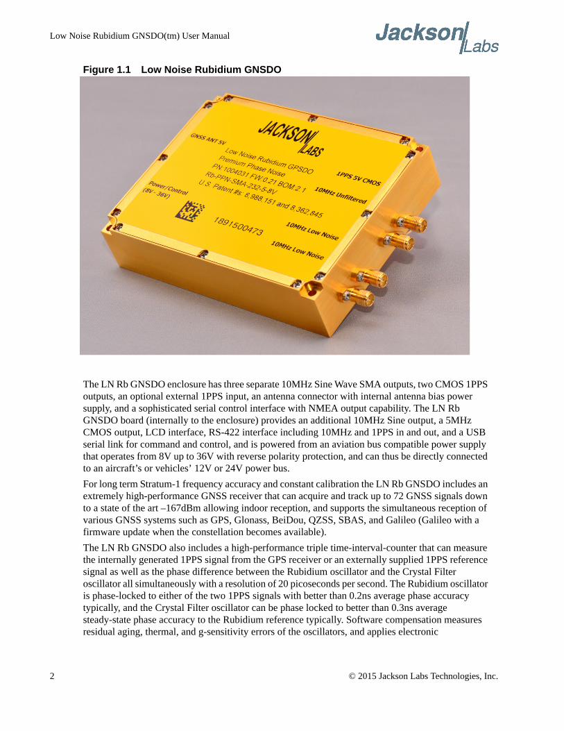
Figure 1.1 Low Noise Rubidium GNSDO
The LN Rb GNSDO enclosure has three separate 10MHz Sine Wave SMA outputs, two CMOS 1PPS outputs, an optional external 1PPS input, an antenna connector with internal antenna bias power supply, and a sophisticated serial control interface with NMEA output capability. The LN Rb GNSDO board (internally to the enclosure) provides an additional 10MHz Sine output, a 5MHz CMOS output, LCD interface, RS-422 interface including 10MHz and 1PPS in and out, and a USB serial link for command and control, and is powered from an aviation bus compatible power supply that operates from 8V up to 36V with reverse polarity protection, and can thus be directly connected to an aircraft’s or vehicles’ 12V or 24V power bus.
For long term Stratum-1 frequency accuracy and constant calibration the LN Rb GNSDO includes an extremely high-performance GNSS receiver that can acquire and track up to 72 GNSS signals down to a state of the art –167dBm allowing indoor reception, and supports the simultaneous reception of various GNSS systems such as GPS, Glonass, BeiDou, QZSS, SBAS, and Galileo (Galileo with a firmware update when the constellation becomes available).
The LN Rb GNSDO also includes a high-performance triple time-interval-counter that can measure the internally generated 1PPS signal from the GPS receiver or an externally supplied 1PPS reference signal as well as the phase difference between the Rubidium oscillator and the Crystal Filter oscillator all simultaneously with a resolution of 20 picoseconds per second. The Rubidium oscillator is phase-locked to either of the two 1PPS signals with better than 0.2ns average phase accuracy typically, and the Crystal Filter oscillator can be phase locked to better than 0.3ns average steady-state phase accuracy to the Rubidium reference typically. Software compensation measures residual aging, thermal, and g-sensitivity errors of the oscillators, and applies electronic
2 © 2015 Jackson Labs Technologies, Inc.
Low Noise Rubidium GNSDO(tm) User Manual
compensation to reduce these residual errors. This error compensation can improve performance especially in GNSS-denied environments, and allows monitoring of the Rubidium and Crystal oscillator health, and detection of performance abnormalities in the system. A complex Built-In Self Test (BIST) system constantly monitors the units’ health and performance and issues a TTL alert as well as pushed or polled status sentences.
Generic NMEA and SCPI (GPIB) commands on three serial interfaces allow very fast integration into legacy applications, and by using the NMEA serial strings the unit can behave like a standard GNSS receiver albeit with better than 1 meter horizontal accuracy typically, and full WAAS/EGNOS/MSAS SBAS as well as Glonass/GPS/BeiDou/QZSS support out-of-the-box. The SCPI command interface is fully backwards compatible to the popular JLT CSAC GPSDO and FireFly command systems, and the unit can thus be used as a drop-in upgrade for applications designed for these legacy Jackson Labs Technologies, Inc. products.
1.2 Operating Principles
A Rubidium Vapor Cell is excited from a VCEL Laser source. The VCEL is modulated at 3.4 GHz to produce a complementary pair of sidebands separated by the Rubidium ground state hyperfine frequency of 6.834 GHz. The hyperfine transition frequency of the Rubidium Vapor cell is affected by adverse environmental influences, and long-term frequency and phase errors are thus present in the MAC as in every Atomic Clock. To calibrate these errors out and to achieve phase-lock to UTC(GNSS), the LN Rb GNSDO uses a GNSS receiver to generate a highly accurate, though unstable 1PPS signal, and this noisy 1PPS signal is compared with a 1PPS signal generated by the MAC-sourced 10MHz using a 20ps time interval counter. The VCEL is digitally tuned to shift the frequency up or down slightly (in 0.001 parts per trillion or 1E-015 resolution) and very slowly to keep the MAC 1PPS reference in phase-lock with the GNSS-generated 1PPS signal. This allows a very close tracking of the UTC 1PPS signal to within tens of nanoseconds anywhere in the world, out-performing even the best free-running Atomic References in the long run. Selection of the GNSS system being activated allows tracking various different world-wide UTC time systems, with UTC(NIST) being a default UTC reference. With this software PLL system the short-term instability of the GPS receiver is filtered by the MAC, while the MAC’s long-term drift is removed by the GNSS receiver, resulting in both a very good short-term as well as tightly UTC phase-locked long-term performance.
The 10MHz VCXO used in the MAC oscillator exhibits fairly high phase noise and numerous spurs on the output of the MAC. A dedicated ovenized phase noise cleanup oscillator is phase-locked to the MAC 10MHz output with selectable time constants (loop bandwidth), which allows generation of world-class phase noise and ADEV performance while maintaining the superior drift performance and stability of the MAC Rubidium. Spurs are also removed to eliminate phantom targets in radar applications for example. Software commands allow either the cleanup phase noise filter, or the raw 10MHz output of the MAC to be selected on the “unfiltered” SMA connector, as well as selection of the 1PPS time domain from the MAC or the Crystal OCXO. Two additional SMA connectors are permanently connected to the filter OCXO to maintain the extremely low phase noise floor. The two oscillators may have small phase offsets to each other, and will have different jitter/wander performance levels. Both the average phase offsets between the GNSS receiver 1PPS and the Rubidium oscillator, as well as the Rubidium oscillator to the OCXO phase offsets can be monitored on a second-to-second basis in 20ps resolution, and this information can be used by a users’ application to compensate phase offsets to sub nanosecond levels.
© 2015 Jackson Labs Technologies, Inc. 3
Low Noise Rubidium GNSDO(tm) User Manual
1.3 General Safety Precautions
The following general safety precautions must be observed during all phases of operation of this instrument. Failure to comply with these precautions or with specific warnings elsewhere in this manual violates safety standards of design manufacture, and intended use of the instrument. Jackson Labs Technologies, Inc. assumes no liability for the customer’s failure to comply with these requirements.
1.3.1 Use an approved Antenna Lightning Protector
The use of an approved, and properly grounded antenna lightning protector on the GNSS antenna is required to prevent damage, injury or death in case of a lightning strike.
1.3.2 Grounding
To avoid damaging the sensitive electronic components in the LN Rb GNSDO always make sure to discharge any built-up electrostatic charge to a good ground source, such as power supply ground. This should be done before handling the circuit board or anything connected to it, i.e. the GNSS antenna.
1.3.3 Power Connections
Make sure to connect the DC power to the device following the polarity indicated in Section 2.6 .
1.3.4 Environmental Conditions
This instrument is intended for indoor use. The use of a properly installed GNSS Antenna Lightning Protector is required. It is designed to operate at a maximum relative non-condensing humidity of 95% and at altitudes of up to 50,000 meters. Refer to the specifications tables for the dc and ac mains voltage requirements and ambient operating temperature range. This product consumes more than 5W of power in steady-state conditions, and will heat up accordingly. Sufficient cooling of the backplate is required to maintain operation at or below +70°C on the backplate.
4 © 2015 Jackson Labs Technologies, Inc.
Low Noise Rubidium GNSDO(tm) User Manual
GNSDO Quick-Start Instructions
2.1 Ordering Options
The LN Rb GNSDO is available in four off-the-shelf configurations depending on performance and pricing requirements. These options are:
• Ultimate Phase Noise, ADEV, Thermal Stability, and Holdover performance (SA35.m)
• Premium Phase Noise, ADEV, Thermal Stability, and Holdover performance (SA33.m)
• Standard Phase Noise, ADEV, Thermal Stability, and Holdover performance (SA31.m)
• Low Power, Low Noise Cesium Vapor Cell (CSAC)
Specifications and loop parameters change between these four ordering options, but all units support the same basic SCPI and GNSS feature set. Differentiation is done by selecting the type and quality of atomic clock oscillator, as well as the type and quality of the Crystal Phase Noise Filter oscillator. The CSAC variant of the product also removes the two direct OCXO 10MHz SMA output connectors from the enclosure. Please refer to the Specifications sheets for additional details on the specifications and parameters of these ordering options.
2.2 Powering Up the Unit
The LN Rb GNSDO may be powered from an external 8V to 36V DC source, with +12V nominal. The unit consumes typically around 18W for several minutes during warmup, and will then settle into a steady state power consumption of less than 5.6W. A power supply of 12V with at least 1.5A capability is suggested. The CSAC ordering option of the product consumes less than 1.4W steady state (less than 0.12A at 12V).
Serial communications can be established through the RS-232 or USB ports at 115,200 baud, 8N1, no flow-control set on the terminal. JLT recommends using the TeraTerm Pro application or Z38xx both of which can be downloaded for free. Once serial communications have been established, the user can try sending, and experimenting with the following useful SCPI commands:
syst:stat?
gps?
© 2015 Jackson Labs Technologies, Inc. 5
Low Noise Rubidium GNSDO(tm) User Manual
sync?
diag?
meas?
csac? or mac?
help?
2.3 Block Diagram
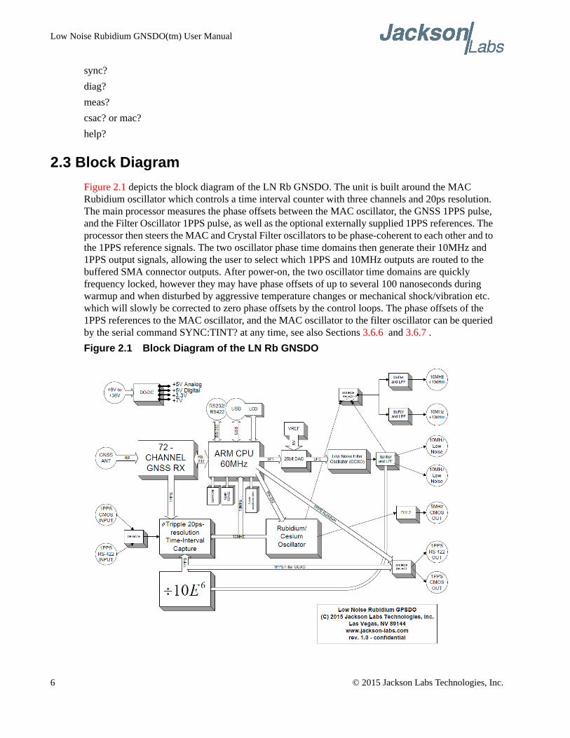
Figure 2.1 depicts the block diagram of the LN Rb GNSDO. The unit is built around the MAC Rubidium oscillator which controls a time interval counter with three channels and 20ps resolution. The main processor measures the phase offsets between the MAC oscillator, the GNSS 1PPS pulse, and the Filter Oscillator 1PPS pulse, as well as the optional externally supplied 1PPS references. The processor then steers the MAC and Crystal Filter oscillators to be phase-coherent to each other and to the 1PPS reference signals. The two oscillator phase time domains then generate their 10MHz and 1PPS output signals, allowing the user to select which 1PPS and 10MHz outputs are routed to the buffered SMA connector outputs. After power-on, the two oscillator time domains are quickly frequency locked, however they may have phase offsets of up to several 100 nanoseconds during warmup and when disturbed by aggressive temperature changes or mechanical shock/vibration etc. which will slowly be corrected to zero phase offsets by the control loops. The phase offsets of the 1PPS references to the MAC oscillator, and the MAC oscillator to the filter oscillator can be queried by the serial command SYNC:TINT? at any time, see also Sections 3.6.6 and 3.6.7 .
Figure 2.1 Block Diagram of the LN Rb GNSDO
6 © 2015 Jackson Labs Technologies, Inc.
Low Noise Rubidium GNSDO(tm) User Manual
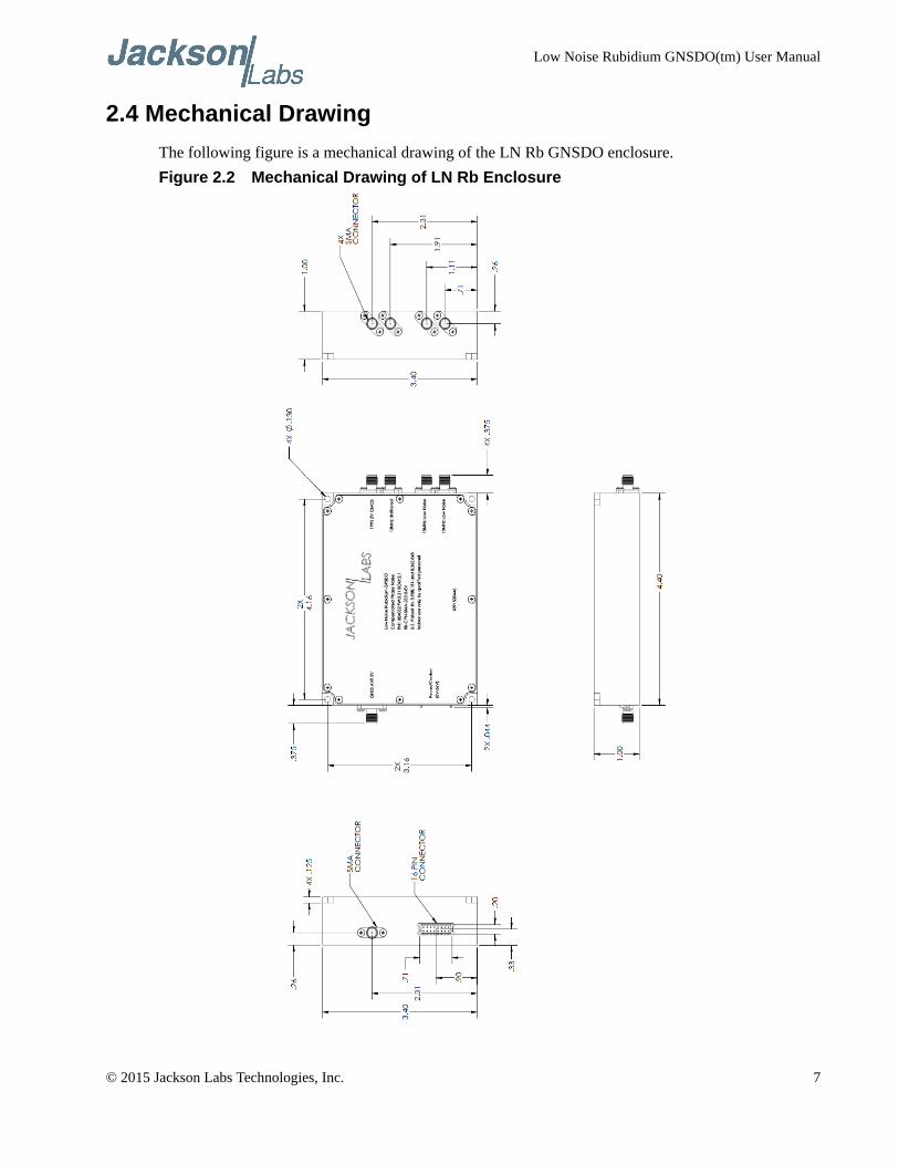
2.4 Mechanical Drawing
The following figure is a mechanical drawing of the LN Rb GNSDO enclosure.
Figure 2.2 Mechanical Drawing of LN Rb Enclosure
© 2015 Jackson Labs Technologies, Inc. 7
Low Noise Rubidium GNSDO(tm) User Manual
2.5 Operating the unit
1) Connect a 5V-compatible GPS or Glonass antenna to the GNSS antenna connector. Either GPS or Glonass, or combined GPS/Glonass L1 antennae are supported. It is recommended to use an active antennae with at least +10dB internal gain, and a maximum allowable gain of +50dB.
2) Plug in a short USB to RS-232 cable adaptor or a standard NULL modem male connector to the RS-232 female plug on the power supply cable harness (supplied with the unit). Plug in a clean DC power source of between 8V to 32V (36V max) to the power pins 15 and 16 of the 16-pin connector J1. Plug in the Ground connection to pins 12 and 14 of connector J1. RS-232 Serial TX and RX signals are available on pins 9 and 8 respectively of connector J1. Make sure not to accidentally short-out adjacent pins 13 and 15 of connector J1 as this would damage the board.
WARNING - WHEN OPERATING THE UNIT OUTSIDE OF ITS ENCLOSURE OR WITH AN OPEN LID: PLEASE MAKE SURE NOT TO CONFUSE POWER CONNECTOR J1 AND LCD CONNECTOR J3 AS THESE TWO CONNECTORS ARE MECHANICALLY IDENTICAL AND ARE THUS EASY TO MIX UP. APPLYING POWER TO LCD CONNECTOR J3 WILL SEVERELY DAMAGE THE PC BOARD
The unit will now discipline its oscillators to the GNSS system. A Lock indication (+3.3V) on pin 7 of connector J1, on the internal Green LED, and on the SCPI status sentences will typically happen in less than 20 minutes after power-on with a GNSS antenna connected. Without a GNSS feed, the unit will work as a traditional Atomic Clock in Rubidium holdover mode, and in this mode the unit will slowly blink the internal Green LED and the LOCK OK output on pin 7 at 0.25Hz to indicate when the unit has internally locked the OCXO to the Rubidium reference, the unit is healthy, and no events are pending. No indication on the internal Green LED and on pin 7 (0V) signifies that an event happened or the unit is not warmed up and locked yet, and this event status can be queried in detail with the SYNC:HEALTH? and other SCPI commands.
Please note that the GNSS receiver establishes the internal antenna-gain right after power-on, so for proper operation the GNSS antenna should always be connected prior to turning on the power supply.
The operator may use Hyperterminal, TeraTerm, GPSCon, Z38xx, or any other serial control software to send commands and query status from the unit. The third-party application GPSCon is recommended for monitoring and controlling the unit. This software is available for purchase at the following website:
http://www.realhamradio.com/gpscon-info.htm
JLT also provides a cost-free control program called Z38xx and this application program can be downloaded from the following website:
www.jackson-labs.com/index.php/support
The RS-232 serial port on the main 16-pin connector operates in parallel to the enclosure-internal USB serial port, and commands can be sent and queried independently to and from both connectors. English language SCPI commands are available to switch the default serial output of the unit from
8 © 2015 Jackson Labs Technologies, Inc.
Low Noise Rubidium GNSDO(tm) User Manual
the RS-232 serial port to the USB port and vice-versa. Please note that using the standard enclosure shields the internal USB connector from being accessible by the user. The PCB will have to be operated outside of the JLT enclosure, or the enclosure will have to be modified to allow access to this and a host of other internally accessible connectors.
2.6 Accessing internal connections
The unit contains various internal connectors such as the RS-422 interfaces, the LCD connector, 5MHz output, and an additional 10MHz buffered output. The unit may be operated with the lid opened (removed), or the lid may be modified to allow additional connections such as low-profile bulkhead DB-9 connectors to provide external accessibility to these connections.
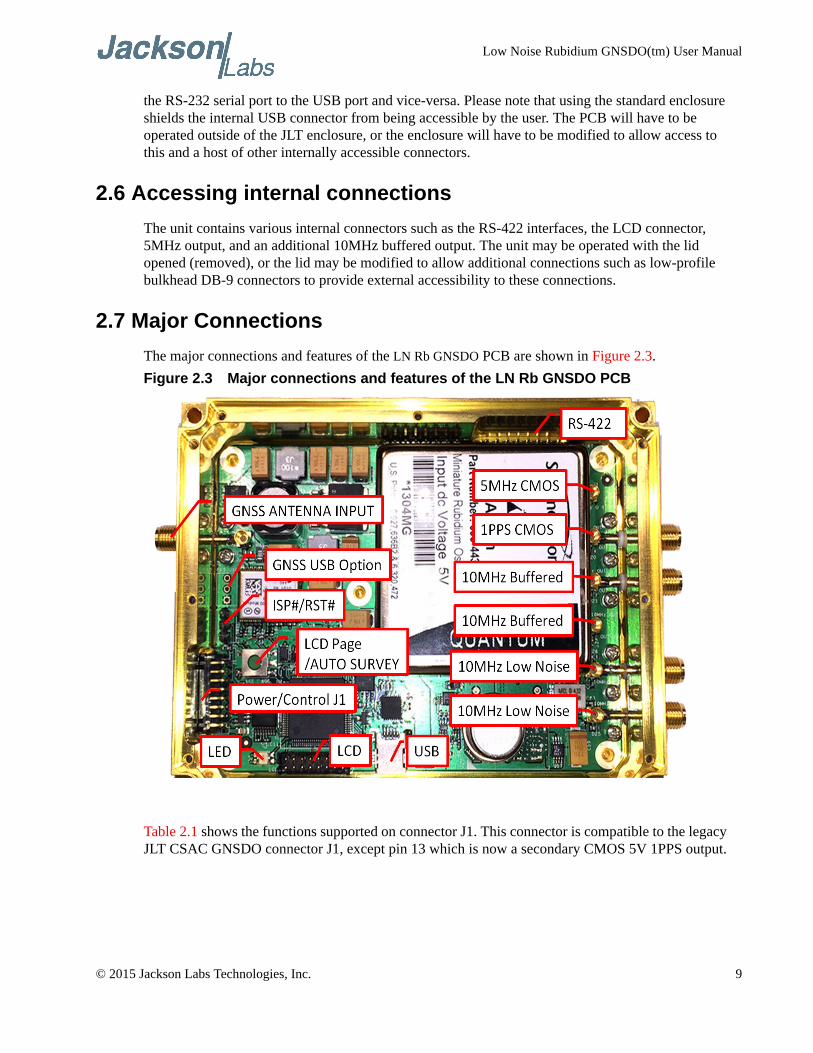
2.7 Major Connections
The major connections and features of the LN Rb GNSDO PCB are shown in Figure 2.3.
Figure 2.3 Major connections and features of the LN Rb GNSDO PCB
Table 2.1 shows the functions supported on connector J1. This connector is compatible to the legacy JLT CSAC GNSDO connector J1, except pin 13 which is now a secondary CMOS 5V 1PPS output.
© 2015 Jackson Labs Technologies, Inc. 9
Low Noise Rubidium GNSDO(tm) User Manual
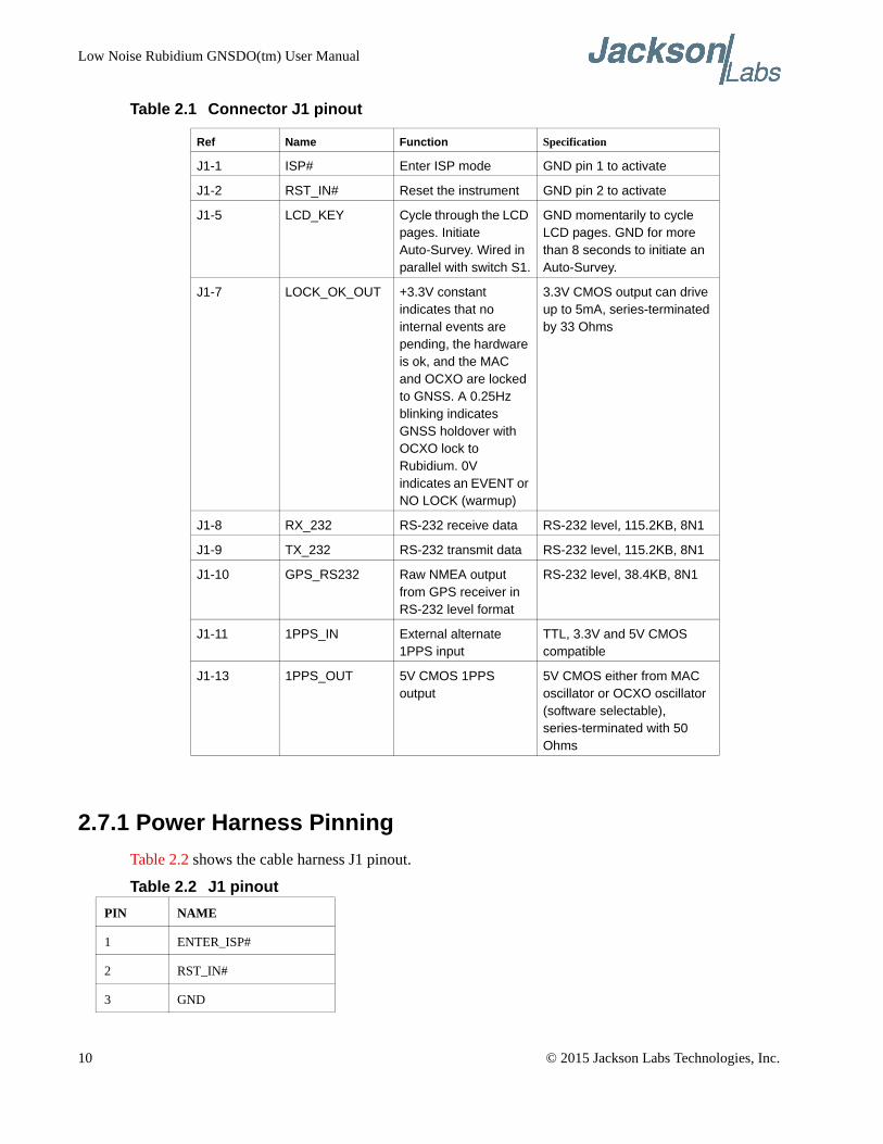
Table 2.1 Connector J1 pinout
2.7.1 Power Harness Pinning
Table 2.2 shows the cable harness J1 pinout.
Table 2.2 J1 pinout
Ref Name Function Specification
J1-1 ISP# Enter ISP mode GND pin 1 to activate
J1-2 RST_IN# Reset the instrument GND pin 2 to activate
J1-5 LCD_KEY Cycle through the LCD pages. Initiate Auto-Survey. Wired in parallel with switch S1.
GND momentarily to cycle LCD pages. GND for more than 8 seconds to initiate an Auto-Survey.
J1-7 LOCK_OK_OUT +3.3V constant indicates that no internal events are pending, the hardware is ok, and the MAC and OCXO are locked to GNSS. A 0.25Hz blinking indicates GNSS holdover with OCXO lock to Rubidium. 0V indicates an EVENT or NO LOCK (warmup)
3.3V CMOS output can drive up to 5mA, series-terminated by 33 Ohms
J1-8 RX_232 RS-232 receive data RS-232 level, 115.2KB, 8N1
J1-9 TX_232 RS-232 transmit data RS-232 level, 115.2KB, 8N1
J1-10 GPS_RS232 Raw NMEA output from GPS receiver in RS-232 level format
RS-232 level, 38.4KB, 8N1
J1-11 1PPS_IN External alternate 1PPS input
TTL, 3.3V and 5V CMOS compatible
J1-13 1PPS_OUT 5V CMOS 1PPS output
5V CMOS either from MAC oscillator or OCXO oscillator (software selectable), series-terminated with 50 Ohms
PIN NAME
1 ENTER_ISP#
2 RST_IN#
3 GND
10 © 2015 Jackson Labs Technologies, Inc.
Low Noise Rubidium GNSDO(tm) User Manual
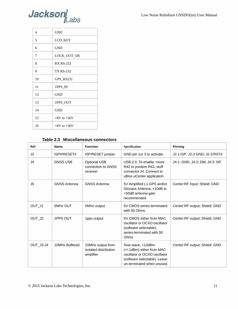
Table 2.3 Miscellaneous connectors
4 GND
5 LCD_KEY
6 GND
7 LOCK_OUT_OK
8 RX RS-232
9 TX RS-232
10 GPS_RS232
11 1PPS_IN
12 GND
13 1PPS_OUT
14 GND
15 +8V to +36V
16 +8V to +36V
Ref Name Function Specification Pinning
J2 ISP#/RESET# ISP/RESET jumper GND pin 1or 3 to activate J2-1:ISP; J2-2:GND; J2-3:RST#
J4 GNSS USB Optional USB connection to GNSS receiver
USB 2.0. To enable: move R42 to position R43, stuff connector J4. Connect to uBlox uCenter application
J4-1: GND; J4-2: DM; J4-3: DP
J5 GNSS Antenna GNSS Antenna 5V Amplified L1 GPS and/or Glonass Antenna, +10dB to +50dB antenna gain recommended
Center:RF Input; Shield: GND
OUT_J1 5MHz OUT 5MHz output 5V CMOS series-terminated with 50 Ohms
Center:RF output; Shield: GND
OUT_J2 1PPS OUT 1pps output 5V CMOS either from MAC oscillator or OCXO oscillator (software selectable), series-terminated with 50 Ohms
Center:RF output; Shield: GND
OUT_J3-J4 10MHz Buffered 10MHz output from isolated distribution amplifier
Sine wave, +13dBm (+/-1dBm) either from MAC oscillator or OCXO oscillator (software selectable). Leave un-terminated when unused.
Center:RF output; Shield: GND
© 2015 Jackson Labs Technologies, Inc. 11
Low Noise Rubidium GNSDO(tm) User Manual
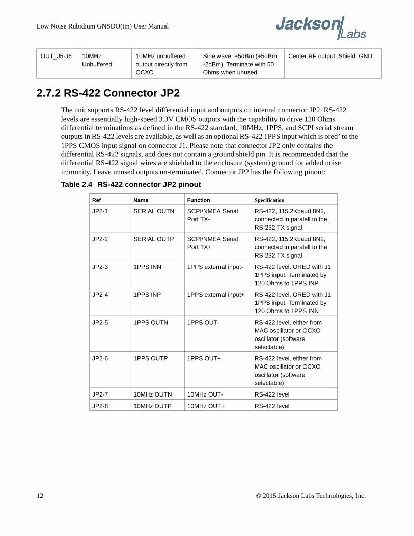
2.7.2 RS-422 Connector JP2
The unit supports RS-422 level differential input and outputs on internal connector JP2. RS-422 levels are essentially high-speed 3.3V CMOS outputs with the capability to drive 120 Ohms differential terminations as defined in the RS-422 standard. 10MHz, 1PPS, and SCPI serial stream outputs in RS-422 levels are available, as well as an optional RS-422 1PPS input which is ored’ to the 1PPS CMOS input signal on connector J1. Please note that connector JP2 only contains the differential RS-422 signals, and does not contain a ground shield pin. It is recommended that the differential RS-422 signal wires are shielded to the enclosure (system) ground for added noise immunity. Leave unused outputs un-terminated. Connector JP2 has the following pinout:
Table 2.4 RS-422 connector JP2 pinout
OUT_J5-J6 10MHz Unbuffered
10MHz unbuffered output directly from OCXO
Sine wave, +5dBm (+5dBm, -2dBm). Terminate with 50 Ohms when unused.
Center:RF output; Shield: GND
Ref Name Function Specification
JP2-1 SERIAL OUTN SCPI/NMEA Serial Port TX-
RS-422, 115.2Kbaud 8N2, connected in paralell to the RS-232 TX signal
JP2-2 SERIAL OUTP SCPI/NMEA Serial Port TX+
RS-422, 115.2Kbaud 8N2, connected in paralell to the RS-232 TX signal
JP2-3 1PPS INN 1PPS external input- RS-422 level, ORED with J1 1PPS input. Terminated by 120 Ohms to 1PPS INP
JP2-4 1PPS INP 1PPS external input+ RS-422 level, ORED with J1 1PPS input. Terminated by 120 Ohms to 1PPS INN
JP2-5 1PPS OUTN 1PPS OUT- RS-422 level, either from MAC oscillator or OCXO oscillator (software selectable)
JP2-6 1PPS OUTP 1PPS OUT+ RS-422 level, either from MAC oscillator or OCXO oscillator (software selectable)
JP2-7 10MHz OUTN 10MHz OUT- RS-422 level
JP2-8 10MHz OUTP 10MHz OUT+ RS-422 level
12 © 2015 Jackson Labs Technologies, Inc.
Low Noise Rubidium GNSDO(tm) User Manual
2.7.3 Harness Connectors J1 and J3
The manufacturer for connectors J1 and J3 is Hirose. A mating housing part number for this connector is available from Digikey, and crimp pins are also available from Digikey for different wire sizes:
http://search.digikey.com/scripts/DkSearch/dksus.dll?Detail&name=H2025-ND
The equivalent part number of the connectors soldered onto the LN Rb GNSDO PCB is:
Hirose DF11-16DP-2DSA01
2.7.4 Connecting External Loads and Sources
The LN Rb GNSDO supports TTL status outputs, RS-232 and RS-422 serial interfaces, two 1PPS, one 5MHz CMOS, and various 10MHz outputs. Some of these require 50 Ohm loads, others require open-ended termination, and some do not require any termination. The unit also supports two ored’ 1PPS inputs with 20ps internal resolution for optional locking to an external 1PPS source such as a SAASM GPS receiver.
The LN Rb PCB also contains two MMCX connectors that are not brought out of the enclosure, but may be used with an open-lid operation as required. These include a 5V CMOS 5MHz output, and an additional buffered and isolated, and unfiltered 10MHz output.
2.7.4.1 5MHz Internal CMOS output
Figure 2.3 shows the 5MHz CMOS MMCX connector internal to the enclosure. This signal is not brought out to SMA connectors. It is internally driven with a 50 Ohms series termination, and should be used with 50 Ohms coax cables that use open-ended termination. Do not use a 50 Ohms termination on this signal. The 10MHz output of the MAC Rubidium is divided by 2, and then drives this connector through a buffer that can source up to 15mA.
2.7.4.2 LOCK_OK Output
The LOCK_OK/EVENT# output on the 16 pin main connector J1 pin 7 can drive an external LED with up to 5mA through a 330 Ohms or higher series resistor. A high (3.3V) on this signal signifies that the unit is fully locked, warmed up, healthy, and no events are pending. A low (0V) on this signal shows that the unit is either unlocked, not fully warmed up, a hardware error happened, or an event is pending. A low thus does NOT necessarily signify that the units output frequency is unlocked, rather the user should query the health status sentence for the event(s) that caused this signal to go low with the command SYNC:HEALTH? See also section 3.6.18
2.7.4.3 10MHz Sine Wave Outputs
The enclosure has three 10MHz output connectors. Two are labeled “LOW NOISE” and one is labeled “UNFILTERED”. The two low-noise outputs are driven directly by the OCXO through a passive splitter, and are completely un-buffered (buffers add about 1dB to 2 dB to the noise floor and
© 2015 Jackson Labs Technologies, Inc. 13
Low Noise Rubidium GNSDO(tm) User Manual
would thus have degraded the units’ noise performance). These two un-buffered outputs should both be terminated into 50 Ohms resistive terminations at all times, and two SMA terminators are typically shipped with the unit for this purpose. Please note that the low noise OCXO has significant sensitivity to load changes, and simply removing or plugging-in a cable on one of these two low-noise SMA connectors may cause the unit to go unlocked, and it could take up to an hour or more to fully recover the units’ stability and frequency accuracy. These two connectors should thus only be changed with the units’ power turned-off
A secondary 10MHz “UNFILTERED” SMA output is available that is fully buffered and isolated, and driven by a multiplexor circuit with software control. The user can select the 10MHz output source to be the MAC Rubidium raw 10MHz output, or a buffered version of the low noise filter oscillator output. Load changes on this connector will not affect frequency accuracy or stability, and the user can switch between the two 10MHz sources at will without affecting the frequency stability of the unit. This connector should thus be used for operations where a cable is connected or removed from the unit during normal operation of the unit. This SMA connector may be left open if unused.
One additional “UNFILTERED” 10MHz output is available internally to the enclosure on an MMCX connector as shown in Figure 2.3. This output is operated in parallel to the SMA unfiltered output, and uses an isolated distribution amplifier.
2.7.4.4 CMOS 1PPS Outputs
The main 1PPS output is driven on the 1PPS SMA connector. The unit also has one independently driven 5V CMOS output on connector J1, pin 13. These outputs are driven with a sub 1ns rise and fall time (more than 1GHz equivalent bandwidth), and include internal 50 Ohms series termination, and should thus be routed in a 50 Ohms coax cable or with short, twisted leads. These drivers can drive up to 15mA, and these signal were thus NOT designed to drive 50 Ohms loads. They are designed for an open-ended 50 Ohms transmission line, or coax cable. DO NOT TERMINATE THESE SIGNALS WITH 50 OHMS LOADS. USE A MINIMUM LOAD OF 1K OHMS OR HIGHER.
2.7.4.5 RS-232 Interfaces
Connector J1 has a standard RS-232 level serial interface for SCPI and NMEA control and output, and one RS-232 level TX signal driven directly by the GNSS receiver. The GNSS receiver output contains binary data and NMEA ASCII data and can be useful if additional GNSS information and low-latency NMEA PVT data is required (the JLT-generated NMEA position and velocity sentences described in section 3.3.3 have a one second latency delay). Nominal baud rates are 115,200 baud, 8N1, no flow control on the SCPI/NMEA port, and 38,400 baud, 8N1 on the GNSS receiver TX port.
2.7.4.6 RS-422 Interface
The unit supports one RS-422 connector internally to the enclosure. This connector has RS-422 standard differential signalling (3.3V differential signalling with 120 Ohms typical termination). A 1PPS output, a 1PPS input (ored’ together with the 1PPS CMOS/TTL input on connector J1), a 10MHz output, and a serial port TX signal are all available in RS-422 format. The three output signals expect 120 Ohms termination, and the 1PPS RS-422 input includes a 120 Ohms internal terminator. Signal routing should be done with 120 Ohms differential wiring, and ground shielding is recommended around the differential pairs for additional noise immunity.
14 © 2015 Jackson Labs Technologies, Inc.
Low Noise Rubidium GNSDO(tm) User Manual
2.7.4.7 1PPS CMOS/TTL Input
A 1PPS CMOS/TTL input is available on pin 11 of the main 16 pin connector J1. This signal is terminated with a 1K Ohms termination resistor. Levels can be 2.5V, 3.3V, or 5V, rising-edge, with at most 15ns rise time recommended. The unit can be instructed to lock to this external 1PPS signal with the SCPI command SYNC:SOUR:MODE EXT as described in section 3.6.4 . It is recommended that the external 1PPS signal has similar or better stability than a late-generation GPS receiver to minimize adding noise to the Rubidium oscillator stability. It can be used to phase-lock the units’ 1PPS and 10MHz outputs to an external source, or to periodically (say once per year) re-calibrate the MAC Rubidium oscillator frequency accuracy.
2.7.5 Connecting the GPS/Glonass Antenna
Connect the GPS/Glonass antenna to connector J6. The unit will work with a GPS, Glonass, or combined GPS/Glonass active antenna. Caution: use a Lightning Arrestor on your Antenna setup. Use an amplified antenna that is 5V compatible. The LN Rb GNSDO GPS receiver is a 72 channel high-sensitivity GNSS receiver with very fast lock time. The unit can either be used in stationary applications using the automatic self-survey (Auto Survey with Position Hold) feature, or it can be used in mobile platforms. Using Position Hold mode improves timing and frequency accuracy especially in GPS/Glonass-challenged antenna locations such as under foliage or with strong multipath signals.
The LN Rb GNSDO is capable of generating industry standard navigation messages (see GPS:GPGGA, GPS:GPZDA, GPS:GPGSV, GPS:PASHR, GPS:GSV, and GPS:GPRMC serial commands in section 3.3.6 ) that are compatible with most GPS/Glonass based navigation software. These navigation messages may either be sent out of the RS-232 and RS-422 serial port, or the USB serial port.
2.7.6 Selecting GNSS Systems
The GNSS receiver of the LN Rb GNSDO is capable of receiving several different GNSS systems at the same time providing better performance especially in challenged or denied environments. The unit may be operated with GPS, SBAS, and Glonass simultaneous operation, or with GPS or Glonass only operation. It can also operate in BeiDou or QZSS only mode where these signals are available. The GNSS receiver allows up to two different GNSS systems to be operated at the same time. Up to 24 satellites can be received at any given time per GNSS system. It is recommended that Glonass operation is only enabled when a Glonass or Glonass/GPS compatible antenna system is being used. Glonass uses wider signal bandwidth and a different carrier frequency, so requires Glonass-compatible splitters, and antennae. It is also recommended that SBAS is enabled whenever GPS or QZSS is selected.
Please note that Glonass reception is disabled by default when the unit is shipped from the factory.
GNSS systems are enabled via the GPS:SYST:SEL serial command, with GPS, SBAS, and QZSS enabled by default. See also section 3.3.27 .
The GNSS receiver generates a 1PPS time signal that is phase synchronized to UTC(GPS) or UTC(Glonass/BeiDou/QZSS). This 1PPS signal is used to frequency-lock the 10MHz Sine-Wave output of the LN Rb GNSDO to UTC, thus disciplining the unit’s Atomic Clock 10MHz frequency output to the relevant UTC reference clock for very high frequency accuracy (typically better than 11
© 2015 Jackson Labs Technologies, Inc. 15
Low Noise Rubidium GNSDO(tm) User Manual
digits of frequency accuracy when locked to GPS or Glonass). Using a high-performance Timing GNSS receiver allows operation with a phase stability error of typically less than +/-10 nanoseconds steady-state anywhere in the world.
2.7.7 Connecting an LCD Display
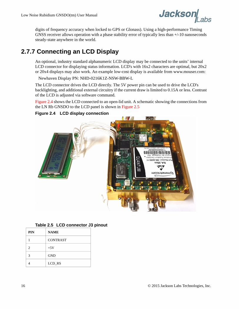
An optional, industry standard alphanumeric LCD display may be connected to the units’ internal LCD connector for displaying status information. LCD's with 16x2 characters are optimal, but 20x2 or 20x4 displays may also work. An example low-cost display is available from www.mouser.com:
Newhaven Display PN: NHD-0216K1Z-NSW-BBW-L
The LCD connector drives the LCD directly. The 5V power pin can be used to drive the LCD's backlighting, and additional external circuitry if the current draw is limited to 0.15A or less. Contrast of the LCD is adjusted via software command.
Figure 2.4 shows the LCD connected to an open-lid unit. A schematic showing the connections from the LN Rb GNSDO to the LCD panel is shown in Figure 2.5
Figure 2.4 LCD display connection
Table 2.5 LCD connector J3 pinout
PIN NAME
1 CONTRAST
2 +5V
3 GND
4 LCD_RS
16 © 2015 Jackson Labs Technologies, Inc.
Low Noise Rubidium GNSDO(tm) User Manual
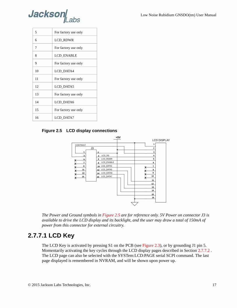
Figure 2.5 LCD display connections
The Power and Ground symbols in Figure 2.5 are for reference only. 5V Power on connector J3 is available to drive the LCD display and its backlight, and the user may draw a total of 150mA of power from this connector for external circuitry.
2.7.7.1 LCD Key
The LCD Key is activated by pressing S1 on the PCB (see Figure 2.3), or by grounding J1 pin 5. Momentarily activating the key cycles through the LCD display pages described in Section 2.7.7.2 . The LCD page can also be selected with the SYSTem:LCD:PAGE serial SCPI command. The last page displayed is remembered in NVRAM, and will be shown upon power up.
5 For factory use only
6 LCD_RDWR
7 For factory use only
8 LCD_ENABLE
9 For factory use only
10 LCD_DATA4
11 For factory use only
12 LCD_DATA5
13 For factory use only
14 LCD_DATA6
15 For factory use only
16 LCD_DATA7
1
2
3
4
5
6
7
8
9
10
11
12
13
14
15
16
1 2
3 4
5 6
7 8
9 10
11 12
13 14
15 16
XXXXXX
XXXX
o
o
+5V
LCD_RS
LCD_RDWR
LCD_ENABLE
LCD_DATA4
LCD_DATA5
LCD_DATA6
LCD_DATA7
CONTRAST
o
o
J3
LCD DISPLAY
© 2015 Jackson Labs Technologies, Inc. 17
Low Noise Rubidium GNSDO(tm) User Manual
Activating the key for 8+ seconds initiates the Auto-Survey sequence and switches the LCD to the Survey status display page. The Auto-Survey can also be initiated with the GPS:SURVey ONCE SCPI command. The unit will automatically enable Position Hold mode after the Auto Survey sequence has ended, which typically takes around 1 hour to complete.
2.7.7.2 LCD Display Pages
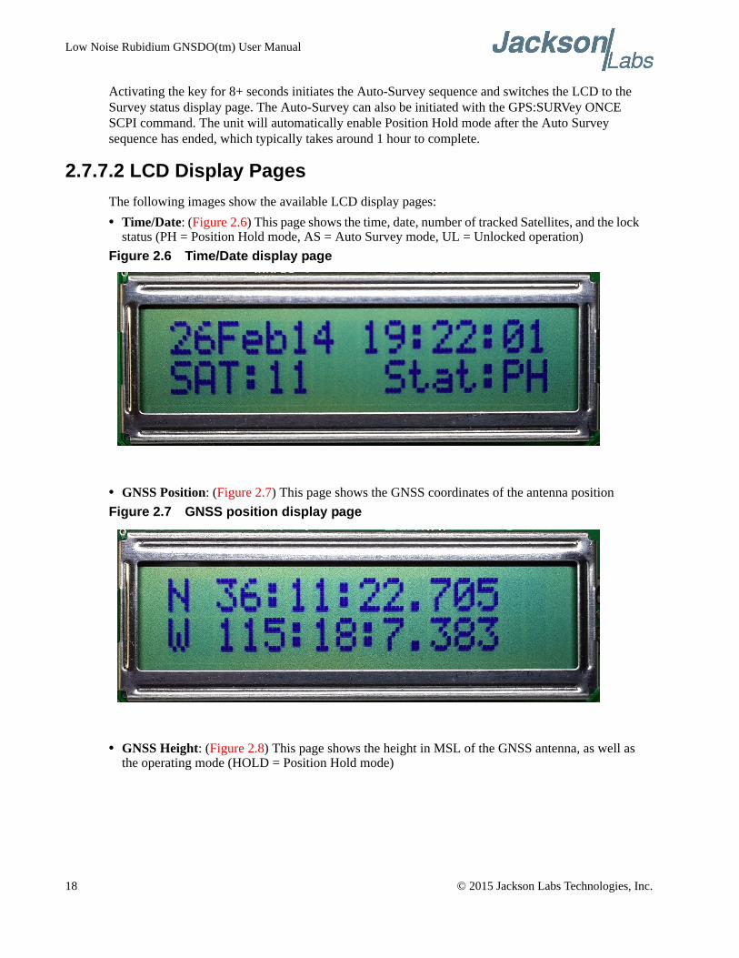
The following images show the available LCD display pages:
• Time/Date: (Figure 2.6) This page shows the time, date, number of tracked Satellites, and the lock status (PH = Position Hold mode, AS = Auto Survey mode, UL = Unlocked operation)
Figure 2.6 Time/Date display page
• GNSS Position: (Figure 2.7) This page shows the GNSS coordinates of the antenna position
Figure 2.7 GNSS position display page
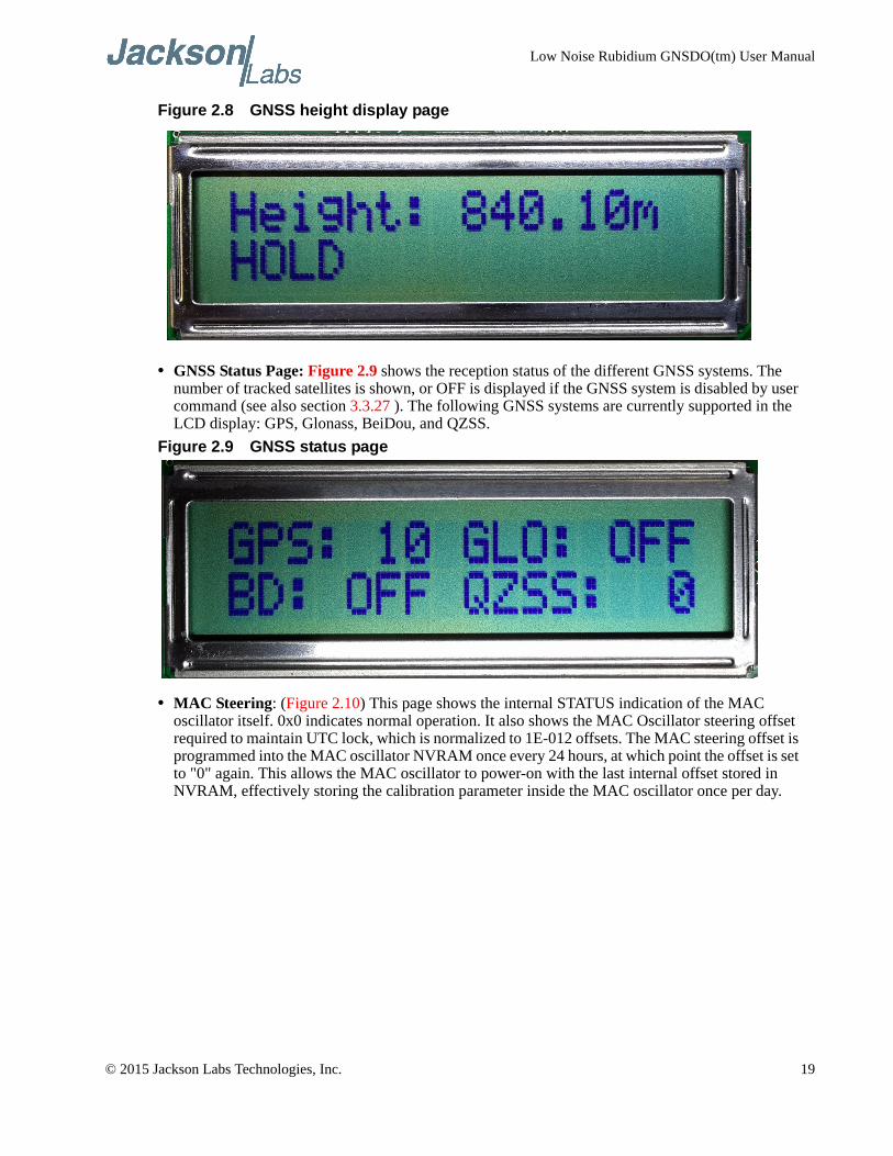
• GNSS Height: (Figure 2.8) This page shows the height in MSL of the GNSS antenna, as well as the operating mode (HOLD = Position Hold mode)
18 © 2015 Jackson Labs Technologies, Inc.
Low Noise Rubidium GNSDO(tm) User Manual
Figure 2.8 GNSS height display page
• GNSS Status Page: Figure 2.9 shows the reception status of the different GNSS systems. The number of tracked satellites is shown, or OFF is displayed if the GNSS system is disabled by user command (see also section 3.3.27 ). The following GNSS systems are currently supported in the LCD display: GPS, Glonass, BeiDou, and QZSS.
Figure 2.9 GNSS status page
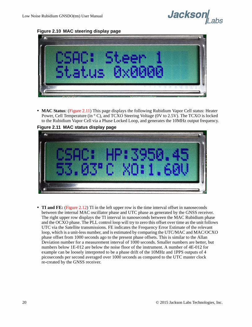
• MAC Steering: (Figure 2.10) This page shows the internal STATUS indication of the MAC oscillator itself. 0x0 indicates normal operation. It also shows the MAC Oscillator steering offset required to maintain UTC lock, which is normalized to 1E-012 offsets. The MAC steering offset is programmed into the MAC oscillator NVRAM once every 24 hours, at which point the offset is set to "0" again. This allows the MAC oscillator to power-on with the last internal offset stored in NVRAM, effectively storing the calibration parameter inside the MAC oscillator once per day.
© 2015 Jackson Labs Technologies, Inc. 19
Low Noise Rubidium GNSDO(tm) User Manual
Figure 2.10 MAC steering display page
• MAC Status: (Figure 2.11) This page displays the following Rubidium Vapor Cell status: Heater Power, Cell Temperature (in ° C), and TCXO Steering Voltage (0V to 2.5V). The TCXO is locked to the Rubidium Vapor Cell via a Phase Locked Loop, and generates the 10MHz output frequency.
Figure 2.11 MAC status display page
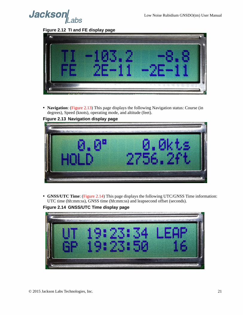
• TI and FE: (Figure 2.12) TI in the left upper row is the time interval offset in nanoseconds between the internal MAC oscillator phase and UTC phase as generated by the GNSS receiver. The right upper row displays the TI interval in nanoseconds between the MAC Rubidium phase and the OCXO phase. The PLL control loop will try to zero this offset over time as the unit follows UTC via the Satellite transmissions. FE indicates the Frequency Error Estimate of the relevant loop, which is a unit-less number, and is estimated by comparing the UTC/MAC and MAC/OCXO phase offset from 1000 seconds ago to the present phase offsets. This is similar to the Allan Deviation number for a measurement interval of 1000 seconds. Smaller numbers are better, but numbers below 1E-012 are below the noise floor of the instrument. A number of 4E-012 for example can be loosely interpreted to be a phase drift of the 10MHz and 1PPS outputs of 4 picoseconds per second averaged over 1000 seconds as compared to the UTC master clock re-created by the GNSS receiver.
20 © 2015 Jackson Labs Technologies, Inc.
Low Noise Rubidium GNSDO(tm) User Manual
Figure 2.12 TI and FE display page
• Navigation: (Figure 2.13) This page displays the following Navigation status: Course (in degrees), Speed (knots), operating mode, and altitude (feet).
Figure 2.13 Navigation display page
• GNSS/UTC Time: (Figure 2.14) This page displays the following UTC/GNSS Time information: UTC time (hh:mm:ss), GNSS time (hh:mm:ss) and leapsecond offset (seconds).
Figure 2.14 GNSS/UTC Time display page
© 2015 Jackson Labs Technologies, Inc. 21
Low Noise Rubidium GNSDO(tm) User Manual
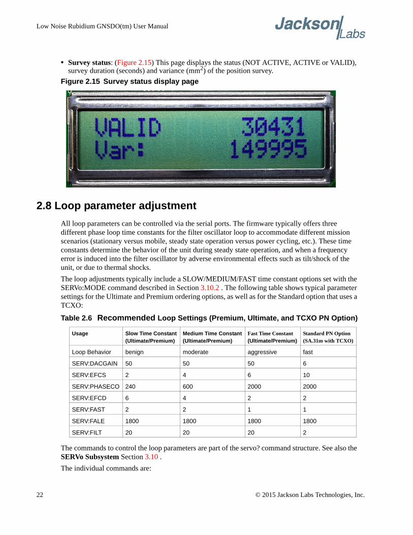
• Survey status: (Figure 2.15) This page displays the status (NOT ACTIVE, ACTIVE or VALID), survey duration (seconds) and variance (mm2) of the position survey.
Figure 2.15 Survey status display page
2.8 Loop parameter adjustment
All loop parameters can be controlled via the serial ports. The firmware typically offers three different phase loop time constants for the filter oscillator loop to accommodate different mission scenarios (stationary versus mobile, steady state operation versus power cycling, etc.). These time constants determine the behavior of the unit during steady state operation, and when a frequency error is induced into the filter oscillator by adverse environmental effects such as tilt/shock of the unit, or due to thermal shocks.
The loop adjustments typically include a SLOW/MEDIUM/FAST time constant options set with the SERVo:MODE command described in Section 3.10.2 . The following table shows typical parameter settings for the Ultimate and Premium ordering options, as well as for the Standard option that uses a TCXO:
Table 2.6 Recommended Loop Settings (Premium, Ultimate, and TCXO PN Option)
The commands to control the loop parameters are part of the servo? command structure. See also the SERVo Subsystem Section 3.10 .
The individual commands are:
Usage Slow Time Constant(Ultimate/Premium)
Medium Time Constant(Ultimate/Premium)
Fast Time Constant(Ultimate/Premium)
Standard PN Option(SA.31m with TCXO)
Loop Behavior benign moderate aggressive fast
SERV:DACGAIN 50 50 50 6
SERV:EFCS 2 4 6 10
SERV:PHASECO 240 600 2000 2000
SERV:EFCD 6 4 2 2
SERV:FAST 2 2 1 1
SERV:FALE 1800 1800 1800 1800
SERV:FILT 20 20 20 2
22 © 2015 Jackson Labs Technologies, Inc.
Low Noise Rubidium GNSDO(tm) User Manual
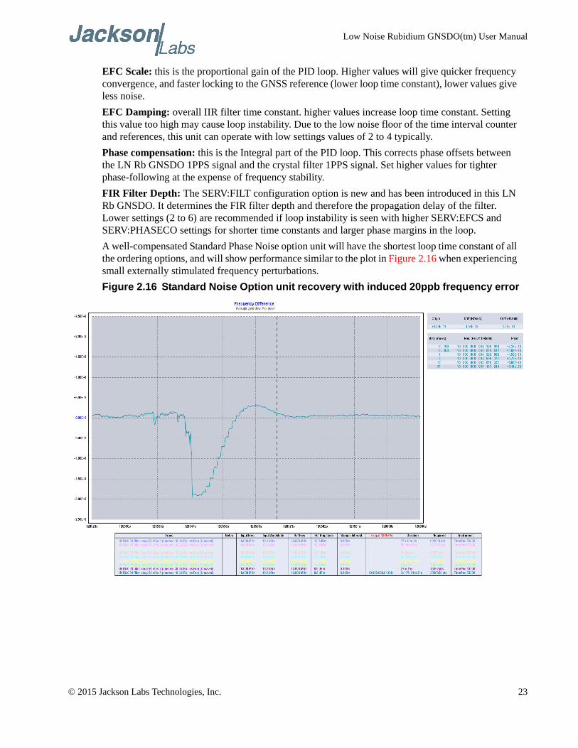
EFC Scale: this is the proportional gain of the PID loop. Higher values will give quicker frequency convergence, and faster locking to the GNSS reference (lower loop time constant), lower values give less noise.
EFC Damping: overall IIR filter time constant. higher values increase loop time constant. Setting this value too high may cause loop instability. Due to the low noise floor of the time interval counter and references, this unit can operate with low settings values of 2 to 4 typically.
Phase compensation: this is the Integral part of the PID loop. This corrects phase offsets between the LN Rb GNSDO 1PPS signal and the crystal filter 1PPS signal. Set higher values for tighter phase-following at the expense of frequency stability.
FIR Filter Depth: The SERV:FILT configuration option is new and has been introduced in this LN Rb GNSDO. It determines the FIR filter depth and therefore the propagation delay of the filter. Lower settings (2 to 6) are recommended if loop instability is seen with higher SERV:EFCS and SERV:PHASECO settings for shorter time constants and larger phase margins in the loop.
A well-compensated Standard Phase Noise option unit will have the shortest loop time constant of all the ordering options, and will show performance similar to the plot in Figure 2.16 when experiencing small externally stimulated frequency perturbations.
Figure 2.16 Standard Noise Option unit recovery with induced 20ppb frequency error
© 2015 Jackson Labs Technologies, Inc. 23
Low Noise Rubidium GNSDO(tm) User Manual
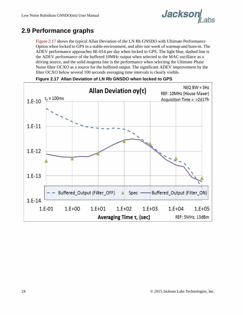
2.9 Performance graphs
Figure 2.17 shows the typical Allan Deviation of the LN Rb GNSDO with Ultimate Performance Option when locked to GPS in a stable environment, and after one week of warmup and burn-in. The ADEV performance approaches 8E-014 per day when locked to GPS. The light blue, dashed line is the ADEV performance of the buffered 10MHz output when selected to the MAC oscillator as a driving source, and the solid magenta line is the performance when selecting the Ultimate Phase Noise filter OCXO as a source for the buffered output. The significant ADEV improvement by the filter OCXO below several 100 seconds averaging time intervals is clearly visible.
Figure 2.17 Allan Deviation of LN Rb GNSDO when locked to GPS
24 © 2015 Jackson Labs Technologies, Inc.
Low Noise Rubidium GNSDO(tm) User Manual
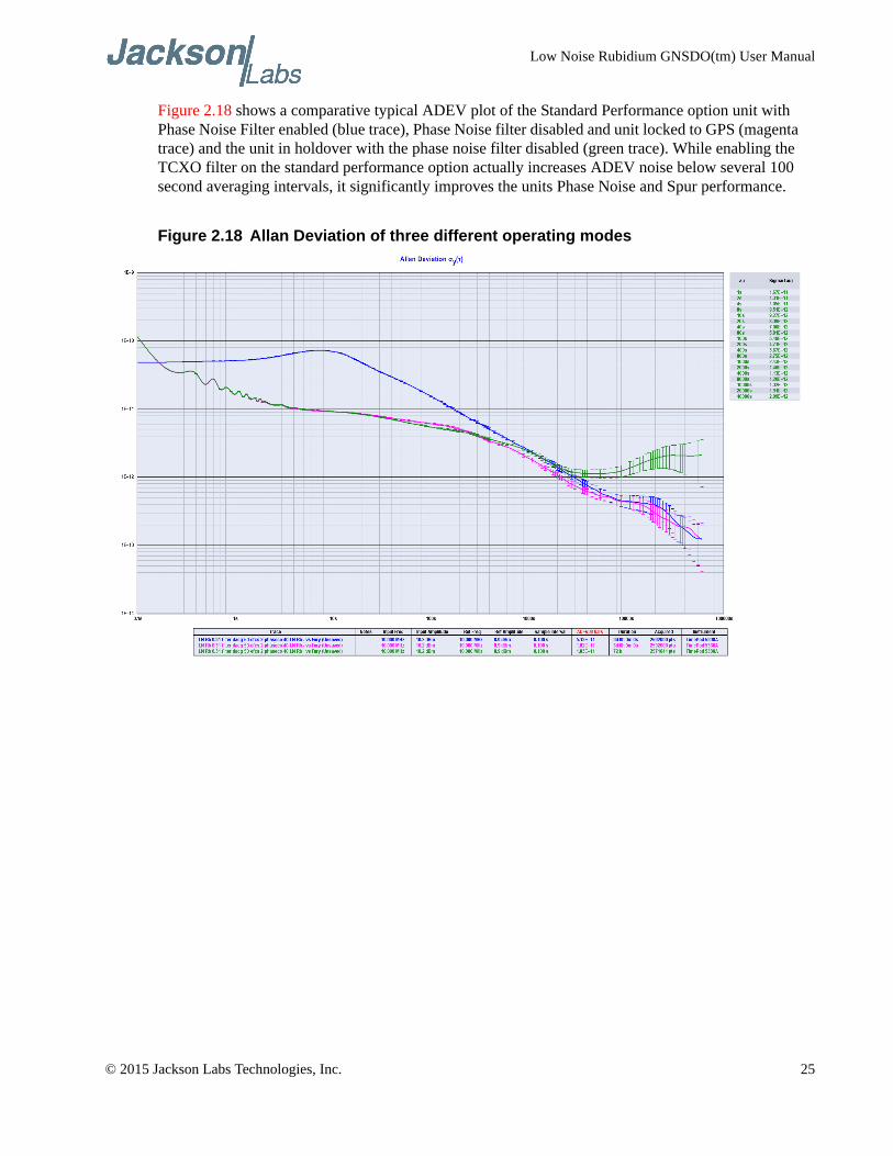
Figure 2.18 shows a comparative typical ADEV plot of the Standard Performance option unit with Phase Noise Filter enabled (blue trace), Phase Noise filter disabled and unit locked to GPS (magenta trace) and the unit in holdover with the phase noise filter disabled (green trace). While enabling the TCXO filter on the standard performance option actually increases ADEV noise below several 100 second averaging intervals, it significantly improves the units Phase Noise and Spur performance.
Figure 2.18 Allan Deviation of three different operating modes
© 2015 Jackson Labs Technologies, Inc. 25
Low Noise Rubidium GNSDO(tm) User Manual
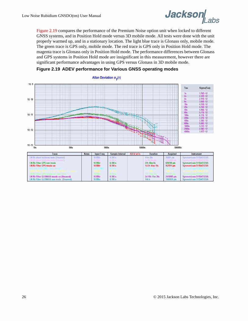
Figure 2.19 compares the performance of the Premium Noise option unit when locked to different GNSS systems, and in Position Hold mode versus 3D mobile mode. All tests were done with the unit properly warmed up, and in a stationary location. The light blue trace is Glonass only, mobile mode. The green trace is GPS only, mobile mode. The red trace is GPS only in Position Hold mode. The magenta trace is Glonass only in Position Hold mode. The performance differences between Glonass and GPS systems in Position Hold mode are insignificant in this measurement, however there are significant performance advantages in using GPS versus Glonass in 3D mobile mode.
Figure 2.19 ADEV performance for Various GNSS operating modes
26 © 2015 Jackson Labs Technologies, Inc.
Low Noise Rubidium GNSDO(tm) User Manual
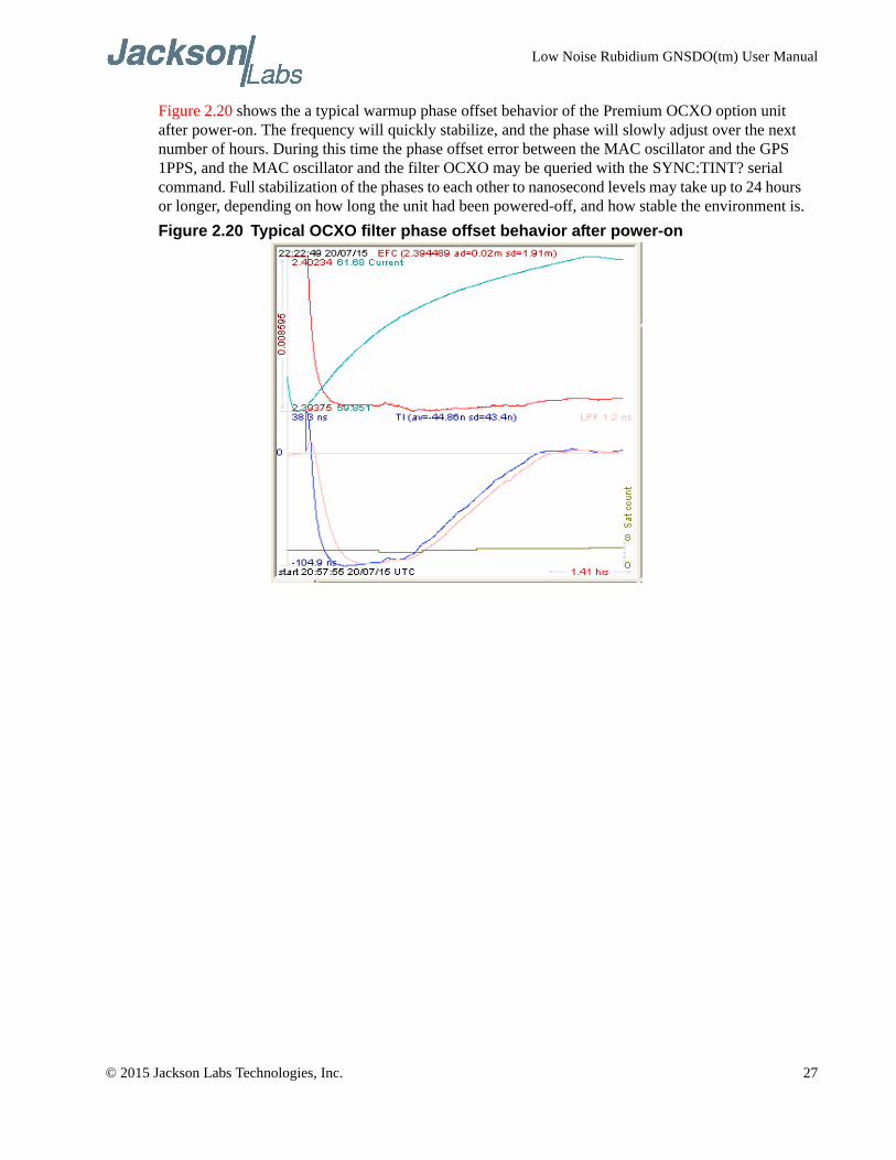
Figure 2.20 shows the a typical warmup phase offset behavior of the Premium OCXO option unit after power-on. The frequency will quickly stabilize, and the phase will slowly adjust over the next number of hours. During this time the phase offset error between the MAC oscillator and the GPS 1PPS, and the MAC oscillator and the filter OCXO may be queried with the SYNC:TINT? serial command. Full stabilization of the phases to each other to nanosecond levels may take up to 24 hours or longer, depending on how long the unit had been powered-off, and how stable the environment is.
Figure 2.20 Typical OCXO filter phase offset behavior after power-on
© 2015 Jackson Labs Technologies, Inc. 27
Low Noise Rubidium GNSDO(tm) User Manual
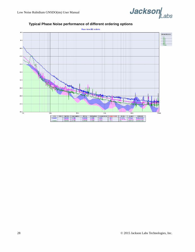
Typical Phase Noise performance of different ordering options
28 © 2015 Jackson Labs Technologies, Inc.
Low Noise Rubidium GNSDO(tm) User Manual
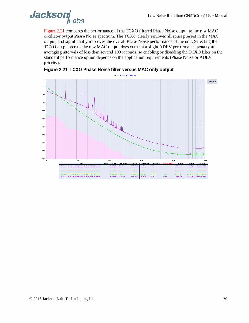
Figure 2.21 compares the performance of the TCXO filtered Phase Noise output to the raw MAC oscillator output Phase Noise spectrum. The TCXO clearly removes all spurs present in the MAC output, and significantly improves the overall Phase Noise performance of the unit. Selecting the TCXO output versus the raw MAC output does come at a slight ADEV performance penalty at averaging intervals of less than several 100 seconds, so enabling or disabling the TCXO filter on the standard performance option depends on the application requirements (Phase Noise or ADEV priority).
Figure 2.21 TCXO Phase Noise filter versus MAC only output
© 2015 Jackson Labs Technologies, Inc. 29
Low Noise Rubidium GNSDO(tm) User Manual
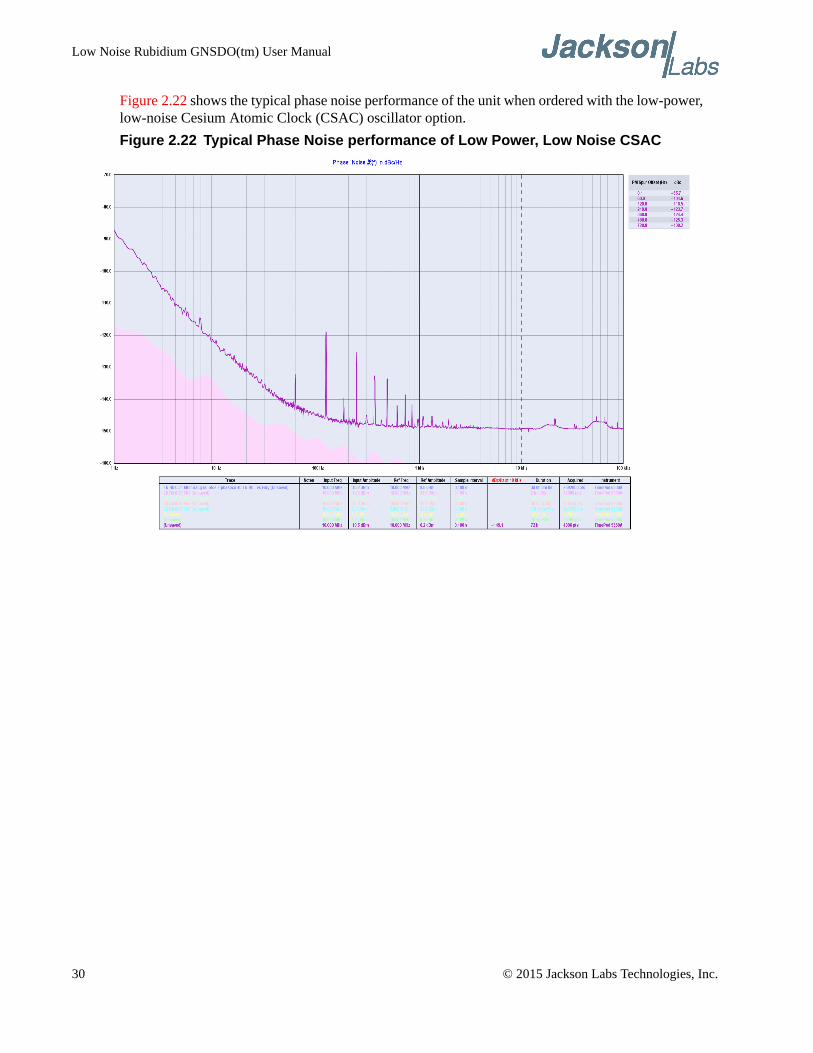
Figure 2.22 shows the typical phase noise performance of the unit when ordered with the low-power, low-noise Cesium Atomic Clock (CSAC) oscillator option.
Figure 2.22 Typical Phase Noise performance of Low Power, Low Noise CSAC
30 © 2015 Jackson Labs Technologies, Inc.
Low Noise Rubidium GNSDO(tm) User Manual
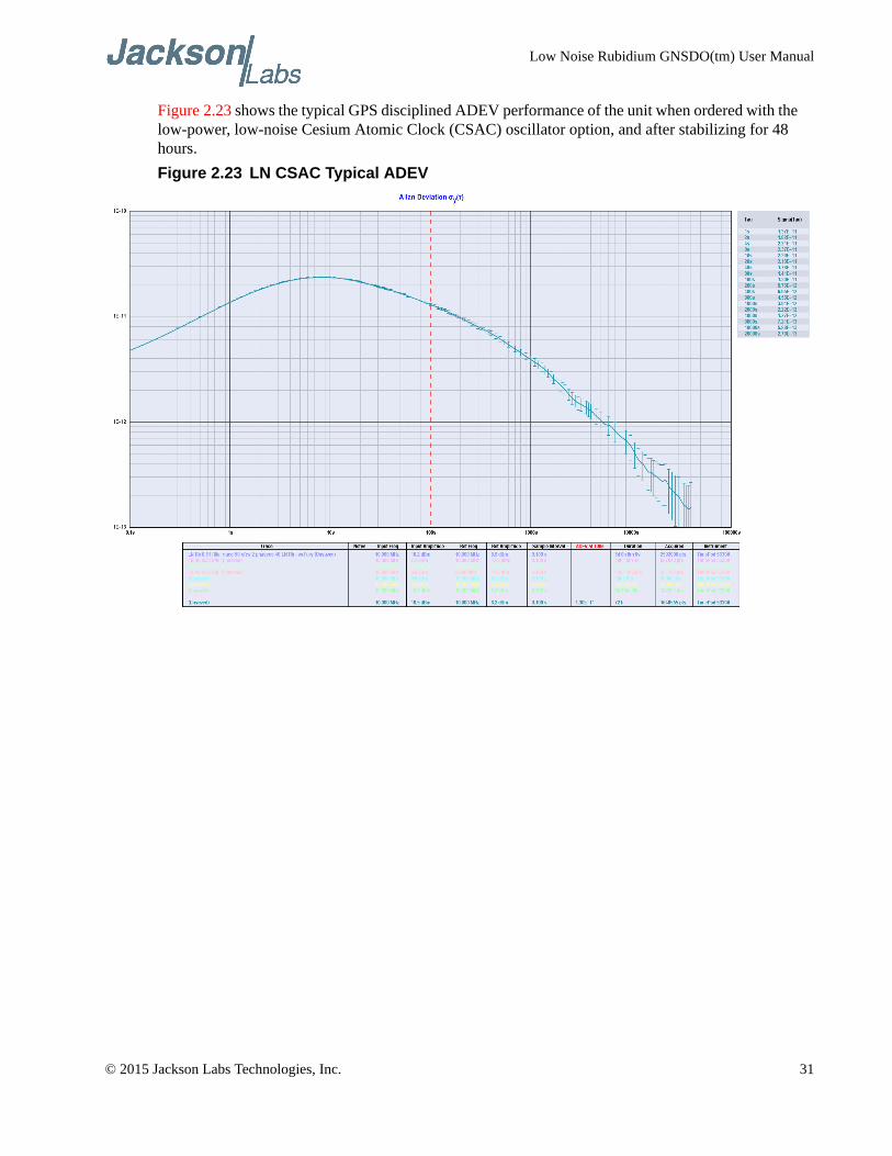
Figure 2.23 shows the typical GPS disciplined ADEV performance of the unit when ordered with the low-power, low-noise Cesium Atomic Clock (CSAC) oscillator option, and after stabilizing for 48 hours.
Figure 2.23 LN CSAC Typical ADEV
© 2015 Jackson Labs Technologies, Inc. 31
Low Noise Rubidium GNSDO(tm) User Manual
32 © 2015 Jackson Labs Technologies, Inc.
Low Noise Rubidium GNSDO User Manual
GNSDO SCPI-Control Quick Start Instructions
3.1 Introduction
The Low Noise Rubidium GNSDO has two serial ports that can be used simultaneously for accessing the SCPI (Standard Commands for Programmable Instrumentation) subsystem by using a host system terminal program such as TeraTerm Pro or HyperTerminal. By default the terminal settings are 115200, 8N1, no flow-control.
There are a number of commands that can be used as listed below. Most of these are identical or similar to Symmetricom/Agilent 58503A commands. To get a listing of the available commands, send the HELP? query. This will return a list of all the available commands for the Low Noise Rubidium GNSDO.
Commands can be entered in either caps or lower-case, and only the characters listed in caps in the below command reference need to be typed-in.
Additional information regarding the SCPI protocol syntax can be found on the following web site:
http://www.ivifoundation.org/scpi/
A basic familiarity with the SCPI protocol is recommended when reading this chapter.
As a Quick-Start, the user may want to try sending the following commands to the unit:
syst:stat?
help?
gps?
sync?
diag?
csac?
© 2015 Jackson Labs Technologies, Inc. 33
Low Noise Rubidium GNSDO User Manual
3.2 General SCPI Commands
3.2.1 *IDN?
This query outputs an identifying string. The response will show the following information:
<company name>, <model number>, <serial number>, <firmware revision>
3.2.2 HELP?
This query returns a list of the commands available for the Low Noise Rubidium GNSDO.
3.3 GPS Subsystem
Note: Please note that Low Noise Rubidium GNSDO displays antenna height in MSL Meters rather than in GPS Meters on all commands that return antenna height [the legacy Fury GPSDO uses GPS height]. The NMEA position fixes are in the WGS84 coordinate system, while the X, Y, and Z velocity vectors are given in the ECEF coordinate system.
The GPS subsystem regroups all the commands related to the control and status of the GNSS receiver. The list of the commands supported is the following:
GPS:SATellite:TRAcking:COUNt?
GPS:SATellite:VISible:COUNt?
GPS:PORT <RS232 | USB>
GPS:PORT?
GPS:GPGGA <int> [0,255]
GPS:GGASTat <int> [0,255]
GPS:GPRMC <int> [0,255]
GPS:GPZDA<int> [0,255]
GPS:GPGSV<int> [0,255]
GPS:PASHR<int> [0,255]
GPS:XYZSPeed
GPS:DYNAMic:MODE <int> [0,7]
GPS:DYNAMic:MODE 8 (Automatic Dynamic Mode)
GPS:DYNAMic:MODE?
GPS:DYNAMic:STATe?
GPS:REFerence:ADELay <float> <s | ns > [-32767ns,32767ns]
GPS:REFerence:PULse:SAWtooth?
GPS:RESET ONCE
GPS:TMODE <ON | OFF | RSTSURV>
GPS:SURVey ONCE
GPS:SURVey:DURation <sec>
34 © 2015 Jackson Labs Technologies, Inc.
Low Noise Rubidium GNSDO User Manual
GPS:SURVey:VARiance <mm^2>
GPS:HOLD:POSition <cm, cm, cm>
GPS:SURVey:STATus?
GPS:INITial:DATE <yyyy,mm,dd>
GPS:INITial:TIME <hour,min,sec>
GPS:SYSTem:SELect [GPS | SBAS | QZSS | GLO]
GPS:JAMlevel?
GPS:FWver?
GPS?
3.3.1 GPS:SATellite:TRAcking:COUNt?
This query returns the number of satellites being tracked.
3.3.2 GPS:SATellite:VISible:COUNt?
This query returns the number of satellites (PRN) that the almanac predicts should be visible, given date, time, and position.
3.3.3 NMEA Support
The following commands allow the Low Noise Rubidium GNSDO to be used as an industry standard navigation multi-GNSS receiver. The GPGGA, GPGSV, GPRMC, PASHR and GPZDA NMEA commands comprise all necessary information about the antenna position, height, velocity, direction, satellite info, fix info, time, date and other information that can be used by standard navigation applications via the Low Noise Rubidium GNSDO serial interface.
Once enabled, the Low Noise Rubidium GNSDO will send out NMEA sentences on the serial transmit pin automatically every N seconds. All incoming serial commands are still recognized by Low Noise Rubidium GNSDO since the serial interface transmit and receive lines operate completely independent of one another.
For compatibility with existing GPS-only products, the Low Noise Rubidium GNSDO’s NMEA output only uses the GPS NMEA sentence headers (GPGGA, GPGSV, etc.) regardless of the GNSS systems enabled. Also, the GPGSV output uses a modified satellite numbering scheme as detailed in Section 3.3.10 to allow all different GNSS system satellites to be differentiated. Any combination of two GNSS systems can be tracked simultaneously such as GPS with Glonass, or QZSS with BeiDou.
Please note that due to internal double-buffering the position, direction, and speed data is delayed by one second from when the GPS receiver internally reported these to the Low Noise Rubidium GNSDO Microprocessor, so the position is valid for the 1PPS pulse previous to the last 1PPS pulse at the time the data is sent (one second delay). The time and date are properly output with correct UTC synchronization to the 1PPS pulse immediately prior to the data being sent.
Once set, the following commands will be stored in NV memory, and generate output information even after power to the unit has been cycled.
© 2015 Jackson Labs Technologies, Inc. 35
Low Noise Rubidium GNSDO User Manual
3.3.4 GPS:PORT <RS232 | USB>
This commands specifies the communication port where the NMEA messages will be sent.
3.3.5 GPS:PORT?
This query returns the port where the NMEA messages are sent.
3.3.6 GPS:GPGGA
This command instructs the Low Noise Rubidium GNSDO to send the NMEA standard string $GPGGA every N seconds, with N in the interval [0,255]. The command is disabled during the initial warm-up phase.
This command has the following format:
GPS:GPGGA <int> [0,255]
GPGGA shows height in MSL Meters, this is different from traditional GPS receivers that display height in GPS Meters. The difference between MSL and GPS height can be significant, 35m or more are common.
3.3.7 GPS:GGASTat
This command instructs the Low Noise Rubidium GNSDO to send a modified version of the NMEA standard string $GPGGA every N seconds, with N in the interval [0,255]. The command is disabled during the initial warm-up phase.
This command has the following format:
GPS:GGASTat <int> [0,255]
This command replaces the regular NMEA GGA validity flag with a decimal number indicating the lock state of the unit. Please see section 3.10.15 for a detailed description of the lock state variable. The command allows capture of the position and other information available in the GGA command, as well as tracking the lock state and health of the unit’s oscillator performance.
GGASTat shows height in MSL Meters, this is different from traditional GPS receivers that display height in GPS Meters. The difference between MSL and GPS height can be significant, 35m or more are common.
3.3.8 GPS:GPRMC
This command instructs the Low Noise Rubidium GNSDO to send the NMEA standard string $GPRMC every N seconds, with N in the interval [0,255]. The command is disabled during the initial warm-up phase.
This command has the following format:
GPS:GPRMC <int> [0,255]
36 © 2015 Jackson Labs Technologies, Inc.
Low Noise Rubidium GNSDO User Manual
3.3.9 GPS:GPZDA
This command instructs the Low Noise Rubidium GNSDO to send the NMEA standard string $GPZDA every N seconds, with N in the interval [0,255]. The command is disabled during the initial warm-up phase.
This command has the following format:
GPS:GPZDA <int> [0,255]
3.3.10 GPS:GPGSV
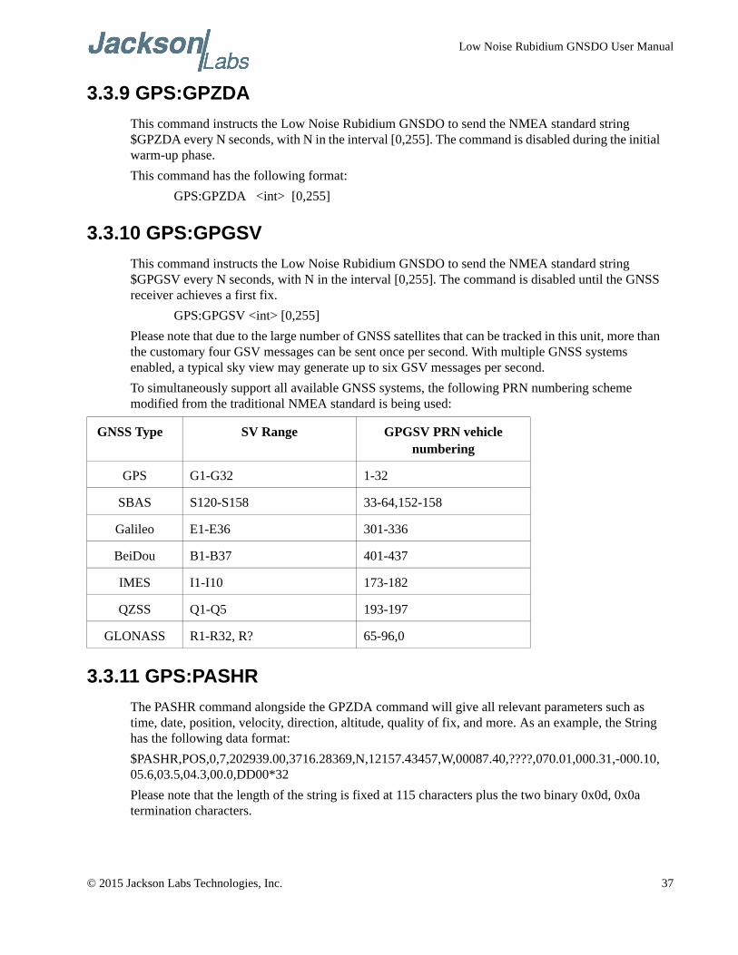
This command instructs the Low Noise Rubidium GNSDO to send the NMEA standard string $GPGSV every N seconds, with N in the interval [0,255]. The command is disabled until the GNSS receiver achieves a first fix.
GPS:GPGSV <int> [0,255]
Please note that due to the large number of GNSS satellites that can be tracked in this unit, more than the customary four GSV messages can be sent once per second. With multiple GNSS systems enabled, a typical sky view may generate up to six GSV messages per second.
To simultaneously support all available GNSS systems, the following PRN numbering scheme modified from the traditional NMEA standard is being used:
3.3.11 GPS:PASHR
The PASHR command alongside the GPZDA command will give all relevant parameters such as time, date, position, velocity, direction, altitude, quality of fix, and more. As an example, the String has the following data format:
$PASHR,POS,0,7,202939.00,3716.28369,N,12157.43457,W,00087.40,????,070.01,000.31,-000.10,05.6,03.5,04.3,00.0,DD00*32
Please note that the length of the string is fixed at 115 characters plus the two binary 0x0d, 0x0a termination characters.
GNSS Type SV Range GPGSV PRN vehicle numbering
GPS G1-G32 1-32
SBAS S120-S158 33-64,152-158
Galileo E1-E36 301-336
BeiDou B1-B37 401-437
IMES I1-I10 173-182
QZSS Q1-Q5 193-197
GLONASS R1-R32, R? 65-96,0
© 2015 Jackson Labs Technologies, Inc. 37
Low Noise Rubidium GNSDO User Manual
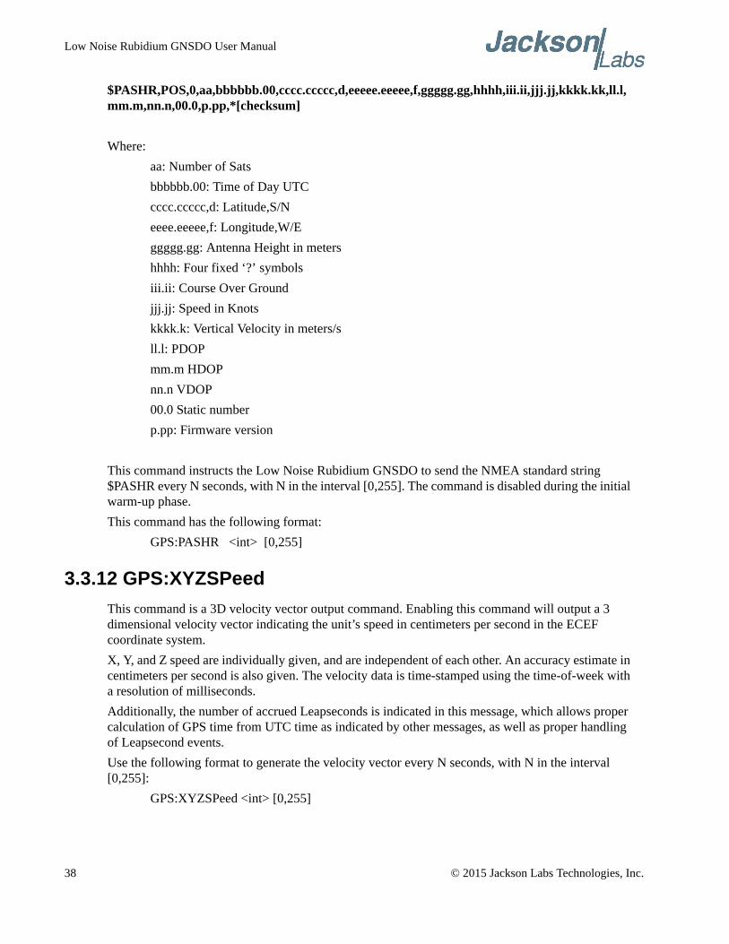
$PASHR,POS,0,aa,bbbbbb.00,cccc.ccccc,d,eeeee.eeeee,f,ggggg.gg,hhhh,iii.ii,jjj.jj,kkkk.kk,ll.l,mm.m,nn.n,00.0,p.pp,*[checksum]
Where:
aa: Number of Sats
bbbbbb.00: Time of Day UTC
cccc.ccccc,d: Latitude,S/N
eeee.eeeee,f: Longitude,W/E
ggggg.gg: Antenna Height in meters
hhhh: Four fixed ‘?’ symbols
iii.ii: Course Over Ground
jjj.jj: Speed in Knots
kkkk.k: Vertical Velocity in meters/s
ll.l: PDOP
mm.m HDOP
nn.n VDOP
00.0 Static number
p.pp: Firmware version
This command instructs the Low Noise Rubidium GNSDO to send the NMEA standard string $PASHR every N seconds, with N in the interval [0,255]. The command is disabled during the initial warm-up phase.
This command has the following format:
GPS:PASHR <int> [0,255]
3.3.12 GPS:XYZSPeed
This command is a 3D velocity vector output command. Enabling this command will output a 3 dimensional velocity vector indicating the unit’s speed in centimeters per second in the ECEF coordinate system.
X, Y, and Z speed are individually given, and are independent of each other. An accuracy estimate in centimeters per second is also given. The velocity data is time-stamped using the time-of-week with a resolution of milliseconds.
Additionally, the number of accrued Leapseconds is indicated in this message, which allows proper calculation of GPS time from UTC time as indicated by other messages, as well as proper handling of Leapsecond events.
Use the following format to generate the velocity vector every N seconds, with N in the interval [0,255]:
GPS:XYZSPeed <int> [0,255]
38 © 2015 Jackson Labs Technologies, Inc.
Low Noise Rubidium GNSDO User Manual
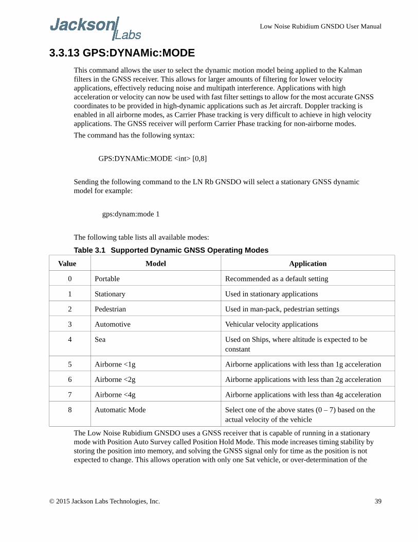
3.3.13 GPS:DYNAMic:MODE
This command allows the user to select the dynamic motion model being applied to the Kalman filters in the GNSS receiver. This allows for larger amounts of filtering for lower velocity applications, effectively reducing noise and multipath interference. Applications with high acceleration or velocity can now be used with fast filter settings to allow for the most accurate GNSS coordinates to be provided in high-dynamic applications such as Jet aircraft. Doppler tracking is enabled in all airborne modes, as Carrier Phase tracking is very difficult to achieve in high velocity applications. The GNSS receiver will perform Carrier Phase tracking for non-airborne modes.
The command has the following syntax:
GPS:DYNAMic:MODE <int> [0,8]
Sending the following command to the LN Rb GNSDO will select a stationary GNSS dynamic model for example:
gps:dynam:mode 1
The following table lists all available modes:
Table 3.1 Supported Dynamic GNSS Operating Modes
The Low Noise Rubidium GNSDO uses a GNSS receiver that is capable of running in a stationary mode with Position Auto Survey called Position Hold Mode. This mode increases timing stability by storing the position into memory, and solving the GNSS signal only for time as the position is not expected to change. This allows operation with only one Sat vehicle, or over-determination of the
Value Model Application
0 Portable Recommended as a default setting
1 Stationary Used in stationary applications
2 Pedestrian Used in man-pack, pedestrian settings
3 Automotive Vehicular velocity applications
4 Sea Used on Ships, where altitude is expected to be constant
5 Airborne <1g Airborne applications with less than 1g acceleration
6 Airborne <2g Airborne applications with less than 2g acceleration
7 Airborne <4g Airborne applications with less than 4g acceleration
8 Automatic Mode Select one of the above states (0 – 7) based on the actual velocity of the vehicle
© 2015 Jackson Labs Technologies, Inc. 39
Low Noise Rubidium GNSDO User Manual
timing pulse. Two modes can be selected for Auto Survey operation (see section 3.3.19 for a description of the GPS:TMODE command):
1) Manually setting Timing Mode to ON with a hard-coded position in NVRAM
2) Enabling Auto Survey to start automatically after power-on by setting Timing Mode to RSTSURV
If either one of the above two GPS:TMODE Auto Survey/Position Hold modes is selected, the GPS:DYNAMIC:MODE command is disabled internally and its setting is ignored as the unit does not expect any motion on the antenna. In this case, the dynamic state as programmed into the GNSS receiver is set to STATIONARY independent of the user selection for GPS:DYNAMIC:MODE.
The current dynamic state being applied to the GNSS receiver can be queried with the command
GPS:DYNAMIC:STATE?
Please note that this command syntax has changed from previous products such as the FireFly-IIA GNSDO units which did not support Position Hold Auto Survey modes.
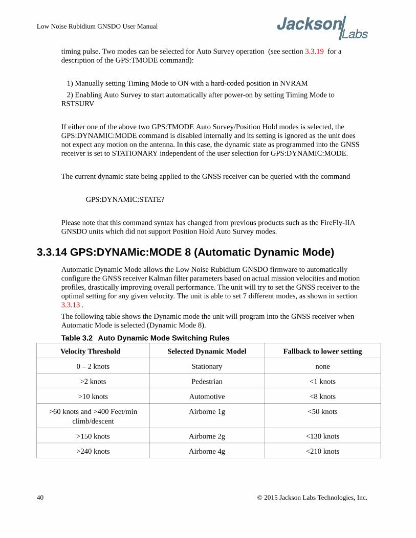
3.3.14 GPS:DYNAMic:MODE 8 (Automatic Dynamic Mode)
Automatic Dynamic Mode allows the Low Noise Rubidium GNSDO firmware to automatically configure the GNSS receiver Kalman filter parameters based on actual mission velocities and motion profiles, drastically improving overall performance. The unit will try to set the GNSS receiver to the optimal setting for any given velocity. The unit is able to set 7 different modes, as shown in section 3.3.13 .
The following table shows the Dynamic mode the unit will program into the GNSS receiver when Automatic Mode is selected (Dynamic Mode 8).
Table 3.2 Auto Dynamic Mode Switching Rules
Velocity Threshold Selected Dynamic Model Fallback to lower setting
0 – 2 knots Stationary none
>2 knots Pedestrian <1 knots
>10 knots Automotive <8 knots
>60 knots and >400 Feet/min climb/descent
Airborne 1g <50 knots
>150 knots Airborne 2g <130 knots
>240 knots Airborne 4g <210 knots
40 © 2015 Jackson Labs Technologies, Inc.
Low Noise Rubidium GNSDO User Manual
In this Automatic mode, the unit will configure the GNSS receiver based on the actual vehicle-velocity:
Please note that in order to switch from the Automotive mode into the first Airborne (1g) mode, both a vehicle velocity greater than 60 knots as well as a climb/descent rate greater than 400 feet per minute are required. Alternatively, a vehicle velocity of greater than 100 Knots will also initiate a switch into airborne-1g mode. Without an appropriate climb/descent, the unit will remain in Automotive mode unless 100 Knots velocity are breached.
The following command returns the setting of the GNSS dynamics model:
GPS:DYNAMic:MODE?
The actual state chosen by the firmware for the GNSS receiver based on vehicle velocity can be obtained with the command:
GPS:DYNAMic:STATe?
A value between 0 and 7 is then returned depending on vehicle dynamics.
The dynamic state is always set to STATIONARY if one of the Position Hold Auto Survey stationary modes is selected using the command GPS:TMODE, as the Position Hold mode setting overrides any dynamic state user setting.
Settings will be applied immediately to the GNSS receiver, and are stored in Non Volatile memory.
3.3.15 GPS:DYNAMic:STATe?
This query returns the actual state of the dynamic model, chosen by the firmware to be applied to the GNSS receiver depending on vehicle velocity. It returns a value between 0 and 7, which correspond to one of the dynamic models defined in the Table in section 3.3.14 .
This state can be different from the user-selected Dynamic model mode for two reasons:
• if the dynamic mode is set to 8 (Automatic mode), the state will reflect the dynamic model being applied to the GNSS receiver depending on actual vehicle dynamics
• if the GPS Timing Mode is set to ON or to RSTSURV, the dynamic state will always be set to 1 (Stationary)
3.3.16 GPS:REFerence:ADELay <float> <s | ns > [-32767ns,32767ns]
The ADELay command allows bi-directional shifting of the 1PPS output in relation to the UTC 1PPS reference in one nanosecond steps. This allows antenna cable delay compensation, as well as retarding or advancing the 1PPS pulse arbitrarily to calibrate different units to each other for
© 2015 Jackson Labs Technologies, Inc. 41
Low Noise Rubidium GNSDO User Manual
example. Typical antenna delays for a 30 foot antenna cable with 1.5ns per foot propagation delay would be compensated with the following command:
GPS:REF:ADEL 45ns
This command can be used to fine-tune different units to have co-incident 1PPS pulse outputs. Please note that during normal operation the 1PPS pulse may wander around the UTC 1PPS pulse while the unit is tracking the GNSS signals. The present offset between the 1PPS output and the UTC 1PPS signal can be queried with the command SYNC:TINT? and this offset should be taken into account when calibrating two unit’s 1PPS outputs to each other, since the lock algorithms will try to steer the Rubidium oscillator for a 0.0ns offset to the UTC 1PPS time-pulse, and the crystal oscillator to a 0.0ns offset to the Rubidium oscillator phase.
3.3.17 GPS:REFerence:PULse:SAWtooth?
This command returns the momentary sawtooth correction factor that the GNSS receiver indicated.
3.3.18 GPS:RESET ONCE
Issues a reset to the internal GNSS receiver. This can be helpful when changing the antenna for example, since the GNSS receiver measures the antenna system’s C/No right after reset, and adjusts its internal antenna amplifier gains accordingly. It takes approximately 1 minute for locking to commence after a GNSS receiver reset, as indicated by the red blinking LED inside the enclosure.
3.3.19 GPS:TMODe <ON | OFF | RSTSURV>
This command selects the Timing Mode of the GNSS receiver.
If the Timing Mode is OFF, the receiver will act as a regular GNSS receiver in 3D mobile mode. This mode has to be chosen if the unit is used with a moving antenna.
If the Timing Mode in ON, the timing features of the GNSS receiver are enabled. At power-up, the Hold position stored in NVRAM will be sent to the GNSS receiver and will be used as the reference. In order to use this mode, the receiver position must be known as exactly as possible. Errors in the Hold position will translate into time errors depending on the satellite constellation.
The Hold position can be set manually by the user or can be the result of a position Auto Survey executed by the GNSS receiver.
If the Timing Mode is set to RSTSURV, the GNSS receiver will start an Auto Survey every time the unit is powered-on and following the Survey sequence, the GNSS receiver will run with the timing features enabled. Once in Position Hold mode, the antenna location should be held completely stationary.
42 © 2015 Jackson Labs Technologies, Inc.
Low Noise Rubidium GNSDO User Manual
3.3.20 GPS:SURVey ONCE
This command starts an Auto Survey. At the end of the Survey, the calculated Hold position will be stored in NVRAM. The Survey parameters can be set with the command GPS:SURVey:DURation and GPS:SURVey:VARiance
3.3.21 GPS:SURVey:DURation <sec>
This command sets the Survey minimal duration.
3.3.22 GPS:SURVey:VARiance <mm^2>
This command specifies the minimum variance of the average position computed during the Survey. This minimum value is used as a threshold under which the GNSS receiver can stop the Survey. The GNSS receiver will stop the Survey when the minimal duration has been reached and the variance of the average position is under the specified minimum variance.
3.3.23 GPS:HOLD:POSition <cm, cm, cm>
This command allows the user to specify manually the exact position of the antenna. This command will overwrite the Hold position in NVRAM. A subsequent Auto Survey will overwrite the Hold position. The Hold position is stored in ECEF coordinates
3.3.24 GPS:SURVey:STATus?
This query displays the current status of the Auto Survey. The status of the survey is in one of the 3 states:
ACTIVE : a survey is in progress
VALID : a survey has been achieved successfully and the GNSS receiver is now using this Hold position as reference.
INVALID : no survey is in progress or has been achieved since the last power cycle.
When in ACTIVE or VALID state, this query will also display the duration, the Hold position in ECEF coordinates and the position variance.
3.3.25 GPS:INITial:DATE <yyyy,mm,dd>
This command allows the manual setting of the internal RTC DATE when operating the unit in GNSS-denied environments. This command is compatible to the PTIME:OUT ON command described in section 3.5 to allow automatic time and date synchronization of two units to each other. The internal RTC is driven by the highly stable Rubidium oscillator’s 10MHz signal, and thus has very high accuracy.
© 2015 Jackson Labs Technologies, Inc. 43
Low Noise Rubidium GNSDO User Manual
3.3.26 GPS:INITial:TIME <hour,min,sec>
This command allows manual setting of the internal RTC TIME when operating the unit in GNSS-denied environments. This command is compatible to the PTIME:OUT ON command described in section 3.5 to allow automatic time and date synchronization of two units to each other. The internal RTC is driven by the highly stable Rubidium oscillator’s 10MHz signal, and thus has very high accuracy.
3.3.27 GPS:SYST:SELect [GPS | SBAS | QZSS | GLO | BD]
This command selects the GNSS systems that are enabled in the GNSS receiver and are used to generated the timing and positioning information for the NMEA data, and to generate the 1PPS reference for the GNSDO. The command is followed by any combination of the currently supported GNSS system abbreviations GPS, SBAS, QZSS, BD (BeiDou), and GLO (GLONASS).
3.3.28 GPS:JAMlevel?
The GNSS receiver will detect, and flag jamming interference with levels ranging from 0 (no jamming) to 255 (strong jamming). Any level exceeding 50 in combination to loss of GNSS lock will cause a SYNC:HEALTH 0x800 event to be flagged, and the unit to disable the LOCK_OUT_OK signal on connector J1.
3.3.29 GPS:FWver?
This command returns the firmware version used inside the GNSS receiver itself.
3.3.30 GPS?
This query displays the configuration, position, speed, height and other relevant data of the GNSS receiver in one convenient location.
3.4 GYRO SUBSYSTEM
The following Gyro commands are supported:
GYRO:MODE <ON | OFF>
GYRO:TRACE <int> [0,255]
GYRO:PORT <RS232 | USB>
GYRO:PORT?
GYRO:CALibrate <float,float,float,float,float,float>
GYRO:CALibrate:COMPute
GYRO:CALibrate:RESET
GYRO:SENSitivity <float,float,float>
GYRO:GLOAD?
44 © 2015 Jackson Labs Technologies, Inc.
Low Noise Rubidium GNSDO User Manual
3.4.1 GYRO:MODE <ON | OFF>
Enables or disables electronic compensation. This feature must be calibrated at the factory before it can be used.
3.4.2 GYRO:TRACE <int> [0,255]
This command sets up the output period of the Accelerometer data (in g’s per axis, and in tilt in Degrees per axis). The fastest period is 50ms (20 outputs per second) achieved when setting the command to GYRO:TRACE 1. The resolution of this command is 1/20 of a second. Setting the command to 0 disables the Accelerometer output.
This command has the following format:
GYRO:TRACE <int> [0,255]
GYRO:TRACE? returns the setting of the period of this command.
The output of the system is in six floating point numbers: the acceleration on the X, Y, and Z axis in g’s, and the Tilt of the X, Y, and Z axis in Degrees (-90 to +90).
Please note that the Accelerometer has its best resolution and accuracy when the earth’s gravitational acceleration is perpendicular to the axis to be measured. Thus the sensors accuracy and resolution will be best when the tilt of any axis is around 0 Degrees. The worst performance (with an accuracy of only ~ +/-5 Degrees) is when any of the axis are at their +/- 90 Degree angles, this is due to the fact that a SIN(g-load) calculation is done to generate the output normalized to Degrees, and the vector is thus least sensitive at +/- 90 Degree angles.
Acceleration can be measured with up to +/-3g range on all three axis. Please note that since the tilt angle is calculated from the acceleration vectors (using gravity as a reference) that the tilt angles will actually exceed +/-90 Degrees when acceleration greater than 1g is applied.
3.4.3 GYRO:PORT <RS232 | USB>
This commands specifies the communication port where the GYRO traces will be sent.
3.4.4 GYRO:PORT?
This query returns the port where the GYRO traces are sent.
3.4.5 GYRO:CAL <float,float,float,float,float,float>
Similar to the GPS:GYRO:CAL command. Used to manually calibrate the gain and offset of the Accelerometer output. Please see the GPS:GYRO:CAL command for details. See also the GYRO:CAL:COMPUTE command for a semi-automated calibration method.
3.4.6 GYRO:CAL:COMPUTE
This command can be used to automatically compute the offset and gain compensation of the accelerometer output for units that are not factory-calibrated. The goal is to have the unit indicate a
© 2015 Jackson Labs Technologies, Inc. 45
Low Noise Rubidium GNSDO User Manual
range of +/- 1.0g on all three axis when slowly rotated through the axis, as well as 0.0g for any axis that is perpendicular to the earth’s gravity.
The user must establish the minimum and maximum g-loads that are displayed on all three axis by slowly tilting the unit over 180 Degrees on all three axis. These values are written down on a piece of paper, and the system calculates the required gain and offset parameters to scale the accelerometer output to +/- 1g peak-to-peak scale, and 0g indication based on entering these values. The GYRO:CAL:COMPUTE command will query the user for the maximum and minimum indicated g-loads. The GYRO:TRACE 10 command can be used to help establish the g-indications on the three different axis to aid in this calibration.
3.4.7 GYRO:SENS and GPS:CAL:RESET
Used for factory calibration of Gyro subsystem.
3.4.8 GYRO:GLOAD?
This command will return the present acceleration on the X, Y, and Z axis.
3.5 PTIME Subsystem
The PTIME subsystem regroups all the commands related to the management of the time.The list of the commands supported is the following:
PTIMe:DATE?
PTIMe:TIME?
PTIMe:TIME:STRing?
PTIMe:TINTerval?
PTIME:OUTput <on|off>
PTIMe:LEAPsecond?
PTIMe:LEAPsecond:PENDing?
PTIMe:LEAPsecond:ACCumulated?
PTIMe:LEAPsecond:DATE?
PTIMe:LEAPsecond:DURation?
PTIME?
3.5.1 PTIMe:DATE?
This query returns the current calendar date. The local calendar date is referenced to UTC time. The year, month, and day are returned.
46 © 2015 Jackson Labs Technologies, Inc.
Low Noise Rubidium GNSDO User Manual
3.5.2 PTIMe:TIME?
This query returns the current 24-hour time. The local time is referenced to UTC time. The hour, minute, and second is returned.
3.5.3 PTIMe:TIME:STRing?
This query returns the current 24-hour time suitable for display (for example, 13:24:56).
3.5.4 PTIMe:TINTerval?
This query is equivalent to the command synchronization:TINTerval
3.5.5 PTIME:OUTput <ON | OFF>
This command allows connecting two units together through the serial port with a null-modem cable, and having the master unit send time and date information to the slave unit. The slave unit’s 1PPS reference input can also be driven by the master unit’s 1PPS output signal, by setting the slave unit to external 1PPS sync mode using the sync:sour:mode next command. This allows time-synchronization at the nanosecond level between two units which can be useful when operating in GPS/GNSS denied environments.
Sending the command PTIM:OUT ON will cause the unit to automatically generate GPS:INIT:DATE and GPS:INIT:TIME sentences on the serial port once per second.
3.5.6 PTIMe:LEAPsecond?
This command returns the results of the four following queries:
PTIMe:LEAPsecond:PENDing?
PTIMe:LEAPsecond:ACCumulated?
PTIMe:LEAPsecond:DATE?
PTIMe:LEAPsecond:DURation?
3.5.7 PTIMe:LEAPsecond:PENDing?
This command returns 1 if the GPS Almanac data contains a future pending leap second data and 0 if no future leap second is pending or Almanac data is not available. The GNSS receiver must have the GPS system enabled for the GPS Almanac to be available.
3.5.8 PTIMe:LEAPsecond:ACCumulated?
This command returns the internally applied leapsecond offset between GPS time and UTC time as stored in the EEPROM (GPS Almanac not received yet) or as indicated by the GNSS receiver (GPS Almanac is available).
© 2015 Jackson Labs Technologies, Inc. 47
Low Noise Rubidium GNSDO User Manual
3.5.9 PTIMe:LEAPsecond:DATE?
This command returns the date of the pending leap second, if any.
3.5.10 PTIMe:LEAPsecond:DURation?
This command returns the duration of the last minute of the day during a leap second event. The returned value is 59, 60 or 61 if GPS Almanac data is available, and 0 otherwise. A response of 60 indicates that no leap second is pending.
3.5.11 PTIME?
This query returns the result of the following queries:
PTIME:DATE?
PTIME:TIME?
PTIME:TINTerval?
PTIME:OUTput?
PTIME:LEAPsecond:ACCumulated?
3.6 SYNChronization Subsystem
This subsystem regroups the commands related to the synchronization of the Low Noise Rubidium GNSDO and filter oscillator with the GNSS receiver or external 1PPS reference. Some commands in the SYNC subsystem depend on the currently selected servo loop from the SERVo:SELect command (see Section 3.10.1 ). Two phase locked loops are running in parallel, and the user must select one of the two phase locked loops prior to interrogation of that particular loop, otherwise it may be unclear which loop is providing the data. The list of the commands supported for this subsystem is the following:
SYNChronization:HOLDover:DURation?
SYNChronization:HOLDover:INITiate
SYNChronization:HOLDover:RECovery:INITiate
SYNChronization:SOURce:MODE <GPS | EXTernal | AUTO>
SYNChronization:SOURce:STATE?
SYNChronization:TINTerval?
SYNChronization:TINTerval:CSAC?
SYNChronization:TINTerval:FILTer?
SYNChronization:TINTerval:THReshold [50,2000]
SYNChronization:IMMEdiate
SYNChronization:FEEstimate?
SYNChronization:LOCKed?
SYNChronization:OUTput:1PPS:RESET <ON | OFF>
48 © 2015 Jackson Labs Technologies, Inc.
Low Noise Rubidium GNSDO User Manual
SYNChronization:OUTput:1PPS:RESET?
SYNChronization:OUTput:1PPS:DOMAIN <CSAC | FILTer>
SYNChronization:OUTput:1PPS:DOMAIN?
SYNChronization:OUTput:FILTer <ON | OFF>
SYNChronization:OUTput:FILTer?
SYNChronization:HOLDover:STATe?
SYNChronization?
3.6.1 SYNChronization:HOLDover:DURation?
This query returns the duration of the present or most recent period of operation in the holdover and holdover processes. This is the length of time the Rubidium oscillator was not locked to the GNSS receiver or external 1PPS reference, and thus “coasting”. The time units are seconds. The first number in the response is the holdover duration. The duration units are seconds, and the resolution is 1 second. If the Receiver is in holdover, the response quantifies the current holdover duration. If the Receiver is not in holdover, the response quantifies the previous holdover. The second number in the response identifies the holdover state. A value of 0 indicates the GNSDO is not in holdover; a value of 1 indicates the GNSDO is in holdover. This command only operates on the Rubidium oscillator servo loop.
3.6.2 SYNChronization:HOLDover:INITiate
The SYNC:HOLD:INIT and SYNC:HOLD:REC:INIT commands allow the user to manually enter and exit the holdover state, even while GNSS signals or external 1PPS are still being properly received. This forced-holdover allows the unit to effectively disable locking to the GNSS receiver or external 1PPS reference, while still keeping track of the state of the 1PPS output in relation to the UTC 1PPS reference. When the unit is placed into forced-holdover with this command, the unit will indicate the time interval difference between the 1PPS output and the GNSS / external 1PPS signal with the SYNC:TINT:CSAC? command. This allows the user to see the Rubidium oscillator drift when not locked to GPS for testing purposes, or to prevent the GNSS receiver from being spoofed and affecting the Rubidium frequency accuracy. All other frequency-disciplining functions of the unit will behave as if the GNSS antenna or external 1PPS were disconnected from the unit while in this forced-holdover state. This command only operates on the Rubidium oscillator servo loop.
3.6.3 SYNChronization:HOLDover:RECovery:INITiate
This command will disable the forced holdover state (see the SYNC:HOLD:INIT command). The unit will resume normal GNSS locking operation after this command has been sent. This command only operates on the Rubidium oscillator servo loop.
3.6.4 SYNChronization:SOURce:MODE
The Source:Mode command allows an optional external 3.3V CMOS, 5V CMOS or TTL level 1PPS input to be connected to the Low Noise Rubidium GNSDO board on pin 11 of connector harness J1, or via the RS-422 1PPS input (both inputs are ored’ together internally). The unit can use this
© 2015 Jackson Labs Technologies, Inc. 49
Low Noise Rubidium GNSDO User Manual
external 1PPS input instead of the internal, GNSS receiver generated 1PPS. Switching to the external 1PPS is either done manually with the EXT command option, or automatically with the AUTO command option in case the GNSS receiver loses a GNSS fix for any reason. The command has the following format:
SYNChronization:SOURce:MODE <GPS | EXTernal | AUTO>
This command only operates on the Rubidium oscillator servo loop.
3.6.5 SYNChronization:SOURce:STATE?
This query shows the state of the external 1PPS synchronization option. This command only operates on the Rubidium oscillator servo loop.
3.6.6 SYNChronization:TINTerval?
This query returns the difference or Time Interval between the Rubidium or filter oscillator 1PPS output and the loop reference. The resolution is 1E-10 seconds. This command operates on the currently selected servo loop.
3.6.7 SYNChronization:TINTerval:CSAC?
This query returns the Time Interval between the Rubidium oscillator 1PPS output and the GNSS receiver or external 1PPS reference. This command only operates only on the Rubidium oscillator servo loop.
3.6.8 SYNChronization:TINTerval:FILTer?
This query returns the Time Interval between the filter oscillator 1PPS output and the Rubidium oscillator 1PPS output. This command operates only on the filter servo loop.
3.6.9 SYNChronization:IMMEdiate
This command initiates a near-instantaneous alignment of the Rubidium or filter oscillator 1PPS output with the reference 1PPS. To be effective, this command has to be issued while not in holdover. This command operates on the selected servo loop.
3.6.10 SYNChronization:FEEstimate?
This query returns the Frequency Error Estimate, similar to the Allan Variance using a 1000s measurement interval and comparing the internal 1PPS to GNSS or filter oscillator 1PPS offset.
Values less than 1E-012 are below the noise floor, and are not significant. This query reports the value for the selected servo loop
50 © 2015 Jackson Labs Technologies, Inc.
Low Noise Rubidium GNSDO User Manual
3.6.11 SYNChronization:LOCKed?
This query returns the lock state (0=OFF, 1=ON) of the PLL controlling the Rubidium or filter oscillator. This query reports the value for the selected servo loop
3.6.12 SYNChronization:OUTput:1PPs:RESET <ON | OFF>
This command allows the generation of the 1PPS pulse upon power-on without an external GNSS antenna being connected to the unit. By default the unit does not generate a 1PPS pulse until the GNSS receiver has locked onto the Satellites. With the command SYNC:OUT:1PPS:RESET ON the unit can now be configured to generate an asynchronous 1PPS output after power-on even if a GNSS antenna is not connected to the unit. Once the GNSS receiver locks, the 1PPS pulse will align itself to UTC by stepping in 10 equally spaced steps toward UTC alignment. The default setting is OFF which means the 1PPS pulse is disabled until proper GPS lock is achieved. This command requires a power cycle or system reset to be activated.
3.6.13 SYNChronization:OUTput:1PPs:RESET?
This query returns the 1PPS output on reset setting.
3.6.14 SYNChronization:OUTput:1PPS:DOMAIN <CSAC | FILTer>
This command selects between the Rubidium and filter oscillator 1PPS outputs on the 1PPS SMA connector. The CSAC option selects the Rubidium oscillator 1PPS, while the FILTer option selects the filter oscillator 1PPS. The phase of these two selections may vary by more than 100ns during warmup, and this phase difference can be queried by commands described in section 3.6.6 .
3.6.15 SYNChronization:OUTput:1PPS:DOMAIN?
This query returns the 1PPS output domain setting.
3.6.16 SYNChronization:OUTput:FILTer <ON | OFF>
This command enables / disables the Phase Noise filter on the buffered 10MHz frequency output connectors. If selected (ON) the output of the filter oscillator is routed to the buffered outputs. If de-selected (OFF) the raw 10MHz output of the MAC Rubidium is routed to the buffered outputs.
N.B.: Please note that for the LN CSAC ordering option, this setting always needs to be set to OFF for the unit to function properly. For the LN CSAC version of this product, the filter oscillator is built into the Microsemi CSAC oscillator and thus the external filter oscillator is not present and cannot be enabled.
3.6.17 SYNChronization:OUTput:FILTer?
This query returns the Phase Noise filter setting.
© 2015 Jackson Labs Technologies, Inc. 51
Low Noise Rubidium GNSDO User Manual
3.6.18 SYNChronization:HEAlth?
The SYNChronization:HEAlth? query returns a hexadecimal number indicating the servo loop’s health status. Error flags are encoded in a binary fashion so that each flag occupies one single bit of the binary equivalent of the hexadecimal health-status flag.
This query reports the status of the selected servo loop, see section 3.10.1 .
The following system parameters are monitored and indicated through the health-status indicator. Individual parameters are ‘ored’ together which results in a single hexadecimal value encoding the following system status information:
As an example, if the unit is in GNSS holdover and the UTC phase offset is > 250ns then the following errors would be indicated:
‘Oring’ these values together results in:
0x10 | 0x4 = 0x14
The unit would thus indicate: HEALTH STATUS: 0x14 and the Green LED as well as the LOCK_OK output on connector J1 would go off, indicating an event is pending.
A health status of 0x0 indicates a properly locked, and warmed-up unit that is completely healthy.
3.6.19 SYNChronization:TINTerval:THReshold [50,2000]
This command selects the Rubidium or filter oscillator 1PPS phase-offset threshold as compared to the reference 1PPS at which point the unit will initiate a counter-reset (jam-sync) aligning the Rubidium or filter oscillator generated 1PPS with the reference 1PPS phase. The Rubidium or filter oscillator 1PPS phase is allowed to drift up to this threshold before a jam-sync is initiated. The
If the phase offset to reference is >210ns HEALTH STATUS |= 0x4;
If the run-time is < 200 seconds HEALTH STATUS |= 0x8;
If the reference is in holdover > 60s HEALTH STATUS |= 0x10;
If the Frequency Estimate is out of bounds HEALTH STATUS |= 0x20;
If the short-term-drift (ADEV @ 100s) > 100ns HEALTH STATUS |= 0x100;
For the first 3 minutes after a phase-reset: HEALTH STATUS |= 0x200;
If the Rubidium oscillator indicates an alarm HEALTH STATUS |= 0x400;
If the GNSS receiver indicates a strong jamming signal of >=50 (range is 0 to 255) and has no GNSS fix
HEALTH STATUS |= 0x800;
If the filter oscillator loop is not locked (with Rubidium oscillator loop selected only)
HEALTH STATUS |= 0x1000;
1) UTC phase > 250ns: 0x4
2) GPS in holdover: 0x10
52 © 2015 Jackson Labs Technologies, Inc.
Low Noise Rubidium GNSDO User Manual
Rubidium or filter oscillator phase is slowly and continuously adjusted toward 0ns offset to the reference 1PPS while the phase difference is less than the THReshold phase limit. The default setting is 220ns, allowing a drift of up to +/-220ns. Reaching this selected threshold will cause a jam-sync phase-normalization to be initiated, which will also cause the SYNC:HEALTH? Status to indicate 0x200, and the Green LED to be turned-off for several minutes. This command operates on the selected servo loop, see section 3.10.1 .
3.6.20 SYNChronization?
This query returns the results of the following queries:
SYNChronization:SOURce:MODE?
SYNChronization:SOURce:STATE?
SYNChronization:OUTput:1PPS:RESET?
SYNChronization:OUTput:1PPS:DOMAIN?
SYNChronization:LOCKed?
SYNChronization:HOLDover:STATe?
SYNChronization:HOLDover:DURation?
SYNChronization:FEEstimate?
SYNChronization:TINTerval?
SYNChronization:TINTerval:THReshold
SYNChronization:OUTput:FILTer?
SYNChronization:HEAlth?
3.7 DIAGnostic Subsystem
This subsystem regroups the queries related to the diagnostic of the CSAC.The list of the commands supported for this subsystem is as follows:
DIAGnostic:ROSCillator:EFControl:RELative?
DIAGnostic:ROSCillator:EFControl:ABSolute?
DIAGnostic:ROSCillator:EFControl:ABSolute:CSAC?
DIAGnostic:ROSCillator:EFControl:ABSolute:FILTer?
DIAGnostic:LIFetime:COUNt?
3.7.1 DIAGnostic:ROSCillator:EFControl:RELative?
This query returns the Electronic Frequency Control (EFC) output value of the rubidium or filter oscillator. It returns a percentage value between -100% to +100%. This query returns the value for the selected servo loop, see section 3.10.1 .
© 2015 Jackson Labs Technologies, Inc. 53
Low Noise Rubidium GNSDO User Manual
3.7.2 DIAGnostic:ROSCillator:EFControl:ABSolute?
This query returns the Electronic Frequency Control (EFC) steering value of the Rubidium or filter oscillator in parts-per-trillion (1E-012) or Volts respectively. This query returns the value for the selected servo loop, see section 3.10.1 .
3.7.3 DIAGnostic:ROSCillator:EFControl:ABSolute:CSAC?
This query returns the Electronic Frequency Control (EFC) steering value of the MAC Rubidium oscillator in parts-per-trillion (1E-012).
3.7.4 DIAGnostic:ROSCillator:EFControl:ABSolute:FILTer?
This query returns the Electronic Frequency Control (EFC) steering value of the filter oscillator in Volts.
3.7.5 DIAGnostic:LIFetime:COUNt?
This query returns the time since power on of the MAC Rubidium oscillator in hours.
3.7.6 DIAGnostic?
Sending the command diag? returns the following:
Relative oscillator setting
Absolute oscillator setting
Time since power-on in hours (lifetime)
An example of the syntax:
scpi > diag?
EFControl Relative: 0.025000%
EFControl Absolute: 5
Lifetime : +871
3.8 MEASURE Subsystem
The MEASURE subsystem regroups the queries related to parameters that are measured on-board the Low Noise Rubidium GNSDO.
3.8.1 MEASure:TEMPerature?
Displays the PCB temperature inside the MAC Rubidium and around the filter oscillator.
54 © 2015 Jackson Labs Technologies, Inc.
Low Noise Rubidium GNSDO User Manual
3.8.2 MEASure:VOLTage?
Displays the MAC Rubidium oscillator internal TCXO steering voltage.
3.8.3 MEASure:CURRent?
Legacy SCPI command, instead of OCXO current this command displays either the internal Rubidium temperature or PCB temperature around the filter oscillator. This query reports the value for the selected servo loop, see section 3.10.1 .
3.8.4 MEASure:POWersupply?
Displays the power supply input voltage.
3.8.5 MEASure?
The MEASure? query returns the results of the following four queries:
MEASure:TEMPerature?
MEASure:VOLTage?
MEASure:CURRent?
MEASure:POWersupply?
3.9 SYSTEM Subsystem
This subsystem regroups the commands related to the general configuration of the Low Noise Rubidium GNSDO. The list of the commands supported for this subsystem follows:
SYSTem:COMMunicate:SERial:ECHO <ON | OFF>
SYSTem:COMMunicate:SERial:PROmpt <ON | OFF>
SYSTem:COMMunicate:SERial:BAUD <9600 | 19200 | 38400 | 57600 | 115200>
SYSTem:FACToryreset ONCE
SYSTem:ID:SN?
SYSTem:ID:HWrev?
SYSTem:LCD:CONTrast [0,1.0]
SYSTem:LCD:CONTrast
SYSTem:LCD:PAGE [0,8]
SYSTem:LCD:PAGE?
SYSTem:COMMunicate:USB:BAUD <9600 | 19200 | 38400 | 57600 | 115200>
SYSTem:COMMunicate:USB:BAUD?
SYSTem:STATus?
© 2015 Jackson Labs Technologies, Inc. 55
Low Noise Rubidium GNSDO User Manual
3.9.1 SYSTem:COMMunicate:SERial:ECHO
This command enables/disables echo on the serial port. Echo should be turned off when using the Z38xx application program. This command has the following format:
SYSTem:COMMunicate:SERial:ECHO <ON | OFF>
3.9.2 SYSTem:COMMunicate:SERial:PROmpt
This command enables/disables the prompt “scpi>” on the SCPI command lines. The prompt must be enabled when used with the software GPSCon. This command has the following format:
SYSTem:COMMunicate: SERial:PROmpt <ON | OFF>
3.9.3 SYSTem:COMMunicate:SERial:BAUD
This command sets the RS-232 port serial speed. The serial configuration is always 8 bit, 1 stop bit, no parity, no flow control. Upon Factory reset, the speed is set at 115,200 baud. This command has the following format:
SYSTem:COMMunicate:SERial:BAUD <9600 | 19200 | 38400 | 57600 | 115200>
3.9.4 SYSTem:FACToryreset ONCE
This command applies the Factory Reset setting to the NVRAM. All aging, tempco, and user parameters are overwritten with factory default values, and the unit should be self-calibrated by operating with GNSS reception for 72+ continuous hours.
3.9.5 SYSTem:ID:SN?
This query returns the serial number of the board
3.9.6 SYSTem:ID:HWrev?
This query return the Hardware version of the board
3.9.7 SYSTem:LCD:CONTrast [0,1.0]
This command sets the contrast of the LCD. Typical settings are 0.2
3.9.8 SYSTem:LCD:CONTrast?
This query returns the current contrast of the LCD
56 © 2015 Jackson Labs Technologies, Inc.
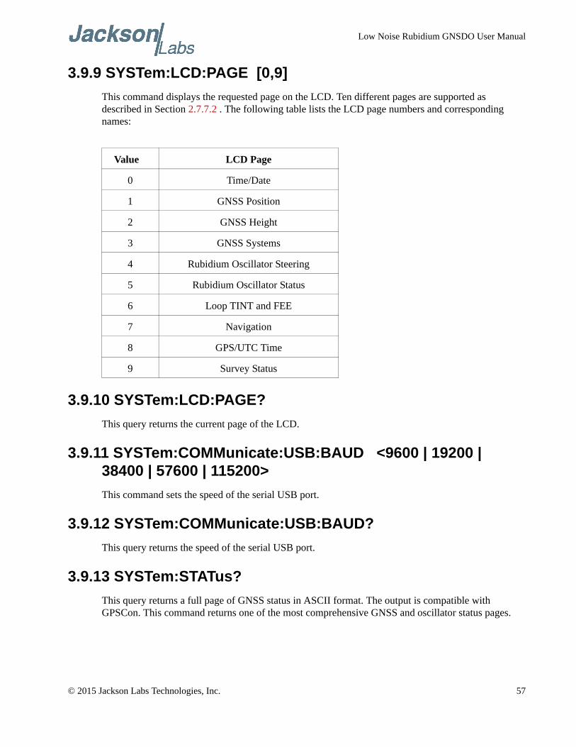
Low Noise Rubidium GNSDO User Manual
3.9.9 SYSTem:LCD:PAGE [0,9]
This command displays the requested page on the LCD. Ten different pages are supported as described in Section 2.7.7.2 . The following table lists the LCD page numbers and corresponding names:
3.9.10 SYSTem:LCD:PAGE?
This query returns the current page of the LCD.
3.9.11 SYSTem:COMMunicate:USB:BAUD <9600 | 19200 | 38400 | 57600 | 115200>
This command sets the speed of the serial USB port.
3.9.12 SYSTem:COMMunicate:USB:BAUD?
This query returns the speed of the serial USB port.
3.9.13 SYSTem:STATus?
This query returns a full page of GNSS status in ASCII format. The output is compatible with GPSCon. This command returns one of the most comprehensive GNSS and oscillator status pages.
Value LCD Page
0 Time/Date
1 GNSS Position
2 GNSS Height
3 GNSS Systems
4 Rubidium Oscillator Steering
5 Rubidium Oscillator Status
6 Loop TINT and FEE
7 Navigation
8 GPS/UTC Time
9 Survey Status
© 2015 Jackson Labs Technologies, Inc. 57
Low Noise Rubidium GNSDO User Manual
3.10 SERVO Subsystem
This subsystem regroups all the commands related to the adjustment of the Rubidium and filter oscillator servo loops:
SERVo:SELect <CSAC | FILTer>
SERVo:MODE <SLOW | MEDium | FAST | AUTO>
SERVo:STATe?
SERVo:LOOP <ON | OFF>
SERVo:COARSEDAC <int> [0 | 255]
SERVo:DACGain <float> [0.1,10000]
SERVo:EFCScale <float>[0.0 , 500.0]
SERVo:EFCDamping <int>[2 , 4000]
SERVo:TEMPCOmpensation <float> [-4000.0, 4000.0]
SERVo:AGINGcompensation <float> [-10.0, 10.0]
SERVo:PHASECOrrection <float> [-500.0, 500.0]
SERVo:1PPSoffset <int> ns
SERVo:TRACe:PORT <RS232 | USB>
SERVo:TRACe <int > [0,255]
SERVo:FASTlock <1,20>
SERVo:FALEngth <100,20000>
SERVo?
3.10.1 SERVo:SELect <CSAC | FILTer>
The Low Noise Rubidium GNSDO has two separate servo loops, one loop for the MAC Rubidium being disciplined by the GNSS receiver, and the second loop for the filter oscillator being disciplined by the MAC Rubidium. This command selects the enabled servo loop for the SCPI interface commands. The selected servo loop for the RS-232 and USB interfaces can be configured independently. Several of the SYNC subsystem commands and all of the SERVO subsystem commands will act on the currently selected servo loop. The CSAC option selects the Rubidium oscillator loop that locks to the GNSS receiver or external 1PPS reference to the atomic oscillator, and the FILTer option selects the filter oscillator loop that locks the filter oscillator to the MAC Rubidium oscillator. The third-party applications GPSCon or Z38xx can be used to graph and monitor either servo loops’ performance by selecting the desired loop with this command.
Please note that for proper operation of the LN CSAC variant of the product this setting needs to be kept at the factory-default setting of SERV:SEL CSAC, because that version of the product does not include an external filter oscillator (the phase noise filter oscillator is located inside the Microsemi LN CSAC oscillator for this version of the product).
58 © 2015 Jackson Labs Technologies, Inc.
Low Noise Rubidium GNSDO User Manual
3.10.2 SERVo:MODE <SLOW | MEDium | FAST | AUTO>
This command allows auto-setting of all of the servo loop parameters to factory-default values as described in section 2.8 with one single command entry. This command is useful in setting the filter loop time constants for differnet mission profiles to accomodate different usage scenarios of the product. The loop time constant of the PLL loop phase-locking the crystal filter oscillator (OCXO) to the MAC Rubidium can be chosen with these settings. The AUTO mode lets the firmware determine by itself which loop time constant is used, thus optimizing the units’ performance dynamically depending on the environmental effects on the OCXO. The AUTO setting will quickly react to phase pertrubations, and will try to set a SLOW setting (long time constant) whenever the unit is in stable conditions to minimize residual noise, and to improve the ADEV performance of the filtered output as much as possible for a particular environment. SLOW settings are useful in stationary applications, whereas MEDIUM or FAST settings are preferred for mobile applications such as in vehicles, man-packs, or aircraft.
The SERVo:MODE? query command responds with the current setting. If individual servo parameters have been manually configured by the user and differ from the recommended settings shown in section 2.8 , then the SERVo:MODE? query responds with CUSTOM.
Please note that the LN CSAC and STANDARD TCXO performance ordering options do not support this command. Settings are only effective on the PREMIUM and ULTIMATE ordering options of the unit.
3.10.3 SERVo:STATe?
This query responds with the current loop parameter settings, SLOW, MEDIUM, FAST or CUSTOM. When the SERVo:MODE command is configured to AUTO, the SERVo:STATe? query responds with the automatically selected loop parameter setting, SLOW, MEDIUM, or FAST. Otherwise the SERVo:STATe? query response matches the SERVo:MODE setting.
3.10.4 SERVo:LOOP <ON | OFF>
This command enables or disables the servo loop for the selected servo loop. With the loop disabled, no changes are made to the oscillator frequency control. Normally the servo loop is left enabled.
3.10.5 SERVo:COARSedac
This command sets the coarse DAC that controls the EFC voltage on the filter servo loop. This command is only available when the filter servo loop is selected. The filter servo control loop automatically adjusts this setting. The user should not have to change this value, but it is useful to establish filter loop lock time constants by artificially applying an incorrect steering voltage to the filter oscillator and monitoring the subsequent loop behavior.
This command has the following format:
SERVo:COARSedac <int> [0,225]
3.10.6 SERVo:DACGain
This command is used for factory setup.
© 2015 Jackson Labs Technologies, Inc. 59
Low Noise Rubidium GNSDO User Manual
3.10.7 SERVo:EFCScale
Controls the Proportional part of the PID loop for the selected servo loop. Typical values are 0.7 to 6.0. Larger values increase the loop control gain (reducing the loop time constant) at the expense of increased noise while locked. Setting this value too high can cause loop instabilities.
This command has the following format:
SERVo:EFCScale <float>[0.0 , 500.0]
3.10.8 SERVo:FILTerlength
Sets the Low Pass pre-filter effectiveness for the time interval counter data for the selected servo loop. Values from 2 to 20 are valid. Larger values result in less noise at the expense of phase delay and may cause loop instability. This command has the following format:
SERVo:FILTerlength <int>[2, 20]
3.10.9 SERVo:EFCDamping
Sets the Low Pass post-filter effectiveness for the EFC control data for the selected servo loop. Values from 2.0 to 50 are typically used. Larger values result in less noise at the expense of phase delay and may cause loop instability. This command has the following format:
SERVo:EFCDamping <int>[2, 4000]
3.10.10 SERVo:TEMPCOmpensation
This parameter is a coefficient that reflects the correlation between the temperature of the Rubidium or filter oscillator versus the required frequency steering. Monitoring the tempco and aging parameters provides a mechanism to track the health of the Rubidium or filter oscillator. Excessively high values that appear from one day to the next could be an indicator of failure on the board. This coefficient is automatically computed and adjusted over time by the Jackson Labs Technologies, Inc. firmware. This command has the following format:
SERVo:TEMPCOmpensation <float> [-4000.0, 4000.0]
3.10.11 SERVo:AGINGcompensation
This parameter is a coefficient that represents the drift of the EFC needed to compensate the natural drift in frequency of the Rubidium or filter oscillator due to aging. This coefficient is automatically computed and adjusted over time by the Jackson Labs Technologies, Inc. firmware. This command has the following format:
SERVo:AGINGcompensation <float> [-10.0, 10.0]
3.10.12 SERVo:PHASECOrrection
This parameter sets the Integral part of the PID loop for the selected servo loop, and therefore the time constant of the phase error correction mechanism. Larger values result in shorter time constants.
60 © 2015 Jackson Labs Technologies, Inc.
Low Noise Rubidium GNSDO User Manual
Loop instability may result if the parameter is set too high. Typical values are 1.0 to 2000 depending on the loop being selected. This command has the following format:
SERVo:PHASECOrrection <float> [-2000.0, 2000.0]
3.10.13 SERVo:1PPSoffset
This command is not supported on the LN Rb GNSDO.
3.10.14 SERVo:TRACe:PORT
This command selects the serial port for trace debug output. This command has the following format:
SERVo:TRACe:PORT <RS232 | USB>
3.10.15 SERVo:TRACe
This command sets the period in seconds for the debug trace for the selected servo loop. Debug trace data can be used with Ulrich Bangert’s “Plotter” utility or Excel to show UTC tracking versus time etc.
This command has the following format:
SERVo:TRACe <int > [0,255]
An example output is described here:
08-07-31 373815 60685 -32.08 -2.22E-11 14 10 6 0x54
[date][1PPS Count][OCXO Fine DAC or MAC Steering][UTC offset ns][Frequency Error Estimate][Sats Visible][Sats Tracked][Lock State][Health Status]
Please see the SYNChronization:HEAlth? command for detailed information on how to decode the health status indicator values. The Lock State variable indicates one of the following states:
Table 3.3 Lock Status Indications
Value State
0 Rubidium/filter oscillator warmup
1 Holdover
2 Locking (Rubidium/filter training)
4 [Value not defined]
5 Holdover, but still phase locked (stays in this state for about 100s after GNSS lock is lost)
6 Locked, and GNSS active
© 2015 Jackson Labs Technologies, Inc. 61
Low Noise Rubidium GNSDO User Manual
3.10.16 SERVo:FASTlock
The FASTlock command enables the FASTLOCK mode, and sets its gain parameter for the selected servo loop. Fastlock works by momentarily multiplying the EFCScale gain to a value determined by this SERVo:FASTlock parameter. Gain values of 1x to 20x can be set, with a gain of 1x (100%) effectively disabling the FASTLOCK feature. By selecting gain values of >1, the PLL loop parameter Proportional gain (SERV:EFCscale) will be increased after power on, thus increasing loop aggressiveness and reducing the PLL lock time and the loop time constant. It is not desirable to maintain a high loop gain for longer than necessary to lock the PLL since high loop gains come at the expense of increased phase noise (reduced short term stability). The FASTLOCK mechanism will automatically reduce the FASTLOCK gain over a period of time specified by the SERVo:FALEngth command, during which time the FASTLOCK gain is slowly decreased from its initial value to 1.0x.
Setting the FASTLOCK gain to 2 for example will result in the Proportional gain value stored in the SERVo:EFCscale parameter to be multiplied by 2x initially after power on. This dynamic gain is slowly reduced until the gain is back to 1.0x, the value stored in the SERVo:EFCScale parameter.
For example, if we set SERVo:FASTlock to 2, and SERVo:FALEngth to 3600, and SERVo:EFCScale is set to 0.7, then initially the unit will multiply the EFCscale by 2x, and an effective EFCscale value of 1.4 is applied to the PLL loop. This increased gain value difference will be reduced every second by 1/3600, so that the gain after two seconds would be: 1.3998, until after 3600 seconds the gain has been reduced back to its long term value of 0.70 as stored in the SERVo:EFCscale parameter.
Disabling the FASTLOCK mode is accomplished by setting the SERVo:FASTlock to 1. This will set the dynamic gain to 1.0, effectively disabling the fastlock feature.
This command has the following format:
SERVo:FASTlock <int> [1,20]
3.10.17 SERVo:FALEngth
This command adjusts the length of time during which the FASTLOCK feature is active, please see
the command SERVo:FASTlock 3.10.16 above.
The length parameter can be set from 100 seconds to 20,000 seconds. The Dynamic FASTLOCK gain is slowly reduced until it reaches a gain of 1.0 after the FALEngth period of seconds. During this time the PLL loop
gain is increased by the amount specified in the SERVo:FASTlock parameter, which will result in a
faster initial phase lock to UTC after power-on, while giving the lowest possible noise floor (best
short term stability) during normal operation.
This command has the following format:
SERVo:FALEngth <int> [100,20000]
3.10.18 SERVo?
This command returns the result of the following queries:
SERVo:SELect?
SERVo:LOOP?
62 © 2015 Jackson Labs Technologies, Inc.
Low Noise Rubidium GNSDO User Manual
SERVo:COARSEDAC? (only with filter servo loop selected)
SERVo:DACGain?
SERVo:EFCScale?
SERVo:EFCDamping?
SERVo:FILTerlength?
SERVo:PHASECOrrection?
SERVo:TEMPCOmpensation?
SERVo:AGINGcompensation?
SERVo:1PPSoffset?
SERVo:TRACe:PORT?
SERVo:TRACe?
SERVo:FASTlock?
SERVo:FALEngth?
3.11 CSAC Subsystem
The following commands are used to query the microcontroller built into the Rubidium oscillator itself. Please note that the CSAC nomenclature is used instead of MAC for backwards compatibility to all legacy JLT CSAC GNSDO products. However, all the commands in the CSAC Subsystem can also be accessed using the MAC name (i.e. MAC:STeer? or MAC:STATus?).
3.11.1 CSAC:RS232?
This query returns the state (OK or FAIL) of the serial communication between the main CPU and the Rubidium oscillator internal microcontroller. When the state is FAIL, there is a communication breakdown, and the unit should be power cycled to clear the communication error.
3.11.2 CSAC:STeer?
This query returns the current Frequency Adjustment in units of parts-per-trillion (1E-12). The Frequency Adjustment is relative to the latched frequency stored in the CSAC or MAC.
3.11.3 CSAC:STeer
This command sets the Frequency Adjustment in units of parts-per-trillion (1E-12). Like the query command described above, the Frequency Adjustment is relative to the latched frequency correction stored in the CSAC or MAC. The control range with this command is +/- 1 ppm.
This command has the following format:
CSAC:STeer <int> [-1000000,1000000]
© 2015 Jackson Labs Technologies, Inc. 63
Low Noise Rubidium GNSDO User Manual
3.11.4 CSAC:STATus?
This query returns the status value in [0,1] as shown below. If the unit does not indicate STATUS 0x0 after 10 minutes after power-on, the MAC may not have locked properly and may need to be power-cycled. This can happen if power supplies with insufficient current capability to handle the MAC warmup currents are used.
3.11.5 CSAC:MODE?
This query returns the Rubidium oscillator mode as shown below:
3.11.6 CSAC:TECcontrol?
This query returns the Rubidium oscillator TEC Control value (in mDegC).
3.11.7 CSAC:TCXO?
This query returns the TCXO Tuning Voltage, 0-2.5 VDC tuning range ~ +/- 10 ppm
3.11.8 CSAC:SIGnal?
This query returns the indication of the Rubidium Vapor Cell DC interrogation signal level in mV.
3.11.9 CSAC:HEATpackage?
This query returns the Physics package heater power in mW.
3.11.10 CSAC:TEMP?
This query returns the Temperature measured by the Rubidium oscillator unit in °C.
3.11.11 CSAC:FWrev?
This query returns the Firmware version of the Rubidium oscillator unit.
0x1 MAC not locked
0x0 MAC locked and healthy
0x0000 Analog tuning disabled
0x0001 Analog tuning enabled
64 © 2015 Jackson Labs Technologies, Inc.
Low Noise Rubidium GNSDO User Manual
3.11.12 CSAC:SN?
This query returns the Serial Number of the Rubidium oscillator in the form YYMMCSNNNNN where YYMM is the year and month of production and NNNNN is the serialized unit of that month.
3.11.13 CSAC:LIFEtime?
This query returns the accumulated number of hours that the Rubidium oscillator has been powered on since the last factory reset of the Low Noise Rubidium GNSDO board. The value is stored in the external NVRAM and updated every hour when the unit is powered on.
3.11.14 CSAC:STeer:LATch ONCE
This command stores the momentary steering offset into the Rubidium oscillator’s internal NVRAM. This is done automatically by the firmware once every 24 hours, so as not to damage the Rubidium oscillator’s NVRAM which has a limited number of write cycles. The user may force this value to be stored into the Rubidium oscillator by issuing the CSAC:STeer:LATch ONCE command
3.11.15 CSAC?
This query displays all the CSAC queries defined above.
© 2015 Jackson Labs Technologies, Inc. 65

Low Noise Rubidium GNSDO User Manual
66 © 2015 Jackson Labs Technologies, Inc.
Low Noise Rubidium GNSDO User Manual
Firmware Upgrade Instructions
4.1 Introduction
The following is a short tutorial on how to upgrade the Low Noise Rubidium GNSDO firmware. Please follow the instructions in order to prevent corrupting the Low Noise Rubidium GNSDO Flash, which may require reflashing at the factory.
With some practice, the entire Flash upgrade can be done in less than two minutes, even though the following seems like a fairly long list of instructions.
4.2 ISP Flash Loader Utility Installation
Jackson Labs Technologies, Inc. recommends using the Flash Magic utility to upgrade the contents of Flash memory on the Low Noise Rubidium GNSDO. It is available for download on the Flash Magic website:
http://www.flashmagictool.com/
Follow the directions given on the website for installing the utility on your computer.
Note: The Philips LPC2000 utility that is used on other Jackson Labs Technologies, Inc. products will not support the newer LPC1768 processor used on the LN Rb GNSDO.
4.3 Putting the PCB into In-Circuit Programming (ISP) mode
Momentarily short-out pins 1 and 3 on the 16-pin main power connector J1, or alternatively pins 1 and 2 of ISP#/RESET# header J2 (on the PCB inside the enclosure) using a jumper wire or other conductive material during power-on (See Figure 4.1). Both LED’s on the PCB should remain off, indicating the unit is properly placed into ISP mode. If the LED’s light up after power-on, the unit is not in ISP mode.
© 2015 Jackson Labs Technologies, Inc. 67
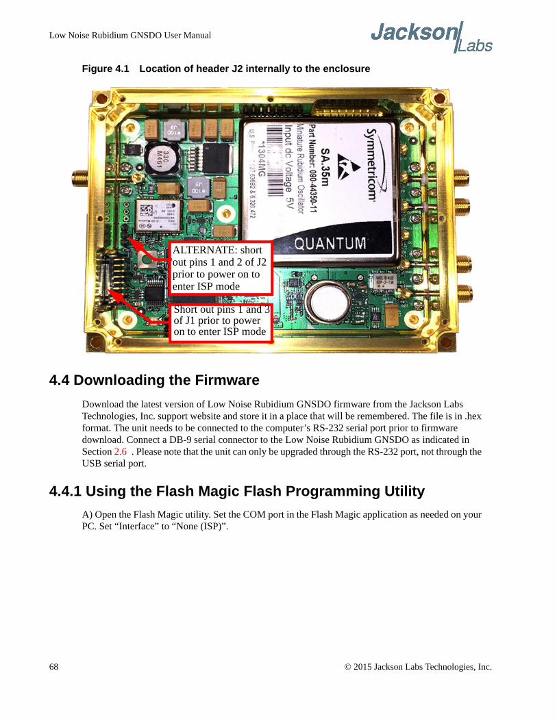
Low Noise Rubidium GNSDO User Manual
Figure 4.1 Location of header J2 internally to the enclosure
4.4 Downloading the Firmware
Download the latest version of Low Noise Rubidium GNSDO firmware from the Jackson Labs Technologies, Inc. support website and store it in a place that will be remembered. The file is in .hex format. The unit needs to be connected to the computer’s RS-232 serial port prior to firmware download. Connect a DB-9 serial connector to the Low Noise Rubidium GNSDO as indicated in Section 2.6 . Please note that the unit can only be upgraded through the RS-232 port, not through the USB serial port.
4.4.1 Using the Flash Magic Flash Programming Utility
A) Open the Flash Magic utility. Set the COM port in the Flash Magic application as needed on your PC. Set “Interface” to “None (ISP)”.
ALTERNATE: short
Short out pins 1 and 3of J1 prior to poweron to enter ISP mode
out pins 1 and 2 of J2prior to power on toenter ISP mode
68 © 2015 Jackson Labs Technologies, Inc.
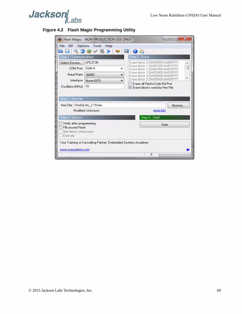
Low Noise Rubidium GNSDO User Manual
Figure 4.2 Flash Magic Programming Utility
© 2015 Jackson Labs Technologies, Inc. 69
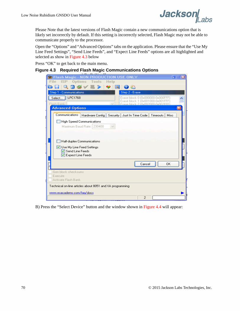
Low Noise Rubidium GNSDO User Manual
Please Note that the latest versions of Flash Magic contain a new communications option that is likely set incorrectly by default. If this setting is incorrectly selected, Flash Magic may not be able to communicate properly to the processor.
Open the “Options” and “Advanced Options” tabs on the application. Please ensure that the “Use My Line Feed Settings”, “Send Line Feeds”, and “Expect Line Feeds” options are all highlighted and selected as show in Figure 4.3 below
Press “OK” to get back to the main menu.
Figure 4.3 Required Flash Magic Communications Options
B) Press the “Select Device” button and the window shown in Figure 4.4 will appear:
70 © 2015 Jackson Labs Technologies, Inc.
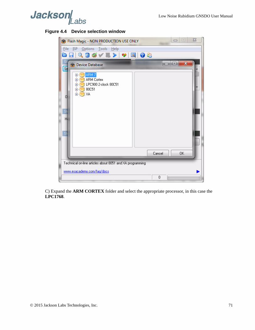
Low Noise Rubidium GNSDO User Manual
Figure 4.4 Device selection window
C) Expand the ARM CORTEX folder and select the appropriate processor, in this case the LPC1768.
© 2015 Jackson Labs Technologies, Inc. 71
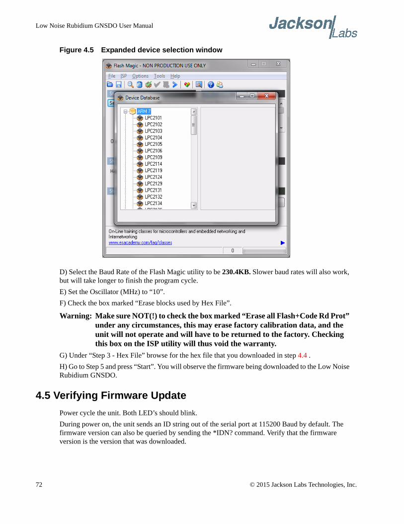
Low Noise Rubidium GNSDO User Manual
Figure 4.5 Expanded device selection window
D) Select the Baud Rate of the Flash Magic utility to be 230.4KB. Slower baud rates will also work, but will take longer to finish the program cycle.
E) Set the Oscillator (MHz) to “10”.
F) Check the box marked “Erase blocks used by Hex File”.
Warning: Make sure NOT(!) to check the box marked “Erase all Flash+Code Rd Prot” under any circumstances, this may erase factory calibration data, and the unit will not operate and will have to be returned to the factory. Checking this box on the ISP utility will thus void the warranty.
G) Under “Step 3 - Hex File” browse for the hex file that you downloaded in step 4.4 .
H) Go to Step 5 and press “Start”. You will observe the firmware being downloaded to the Low Noise Rubidium GNSDO.
4.5 Verifying Firmware Update
Power cycle the unit. Both LED’s should blink.
During power on, the unit sends an ID string out of the serial port at 115200 Baud by default. The firmware version can also be queried by sending the *IDN? command. Verify that the firmware version is the version that was downloaded.
72 © 2015 Jackson Labs Technologies, Inc.

Low Noise Rubidium GNSDO User Manual
GPSCon Utility
5.1 Description
GPSCon is a program useful in the monitoring and controlling a variety of GPS time and frequency standard receivers. It communicates with the receiver using the SCPI command set. GPSCon can be used to monitor either the Rubidium oscillator or filter oscillator servo loops by selecting the desired servo loop with the SERVo:SELect command, see also section 3.10.1 . This utility can be obtained directly from Real Ham Radio.com at the following URL:
http://www.realhamradio.com/gpscon-buy-now.htm
Important note: On newer, faster computers running Windows 7 or 8, GPSCon may not acquire data correctly. Try running GPSCon in Windows XP compatibility mode, and as an administrator. If you encounter problems, it is recommended that you install GPSCon on a slower computer using Windows XP.
5.2 Z38xx Utility
If the GPSCon utility is not available, you may use the Z38xx utility. The Z83XX utility is a PC monitor program for GNSS Disciplined References (GNSDO) which communicate using the SCPI (Standard Commands for Programmable Instrumentation) Protocol. It is available on the Jackson Labs Technologies, Inc. website under the “Support” tab:
http://www.jackson-labs.com/assets/uploads/main/Z38XX_download.zip
The program provides real-time monitoring of the operation of the GNSDO, including status information, GNSS satellite information, timing and control information, holdover prediction, reference Allan Variance and even a UTC clock with second accuracy. It also displays various logs, and stores all measurements on file for later analysis.
5.3 GPSCon Installation
Follow the directions that come with GPSCon for installing the utility on your computer.
© 2015 Jackson Labs Technologies, Inc. 73
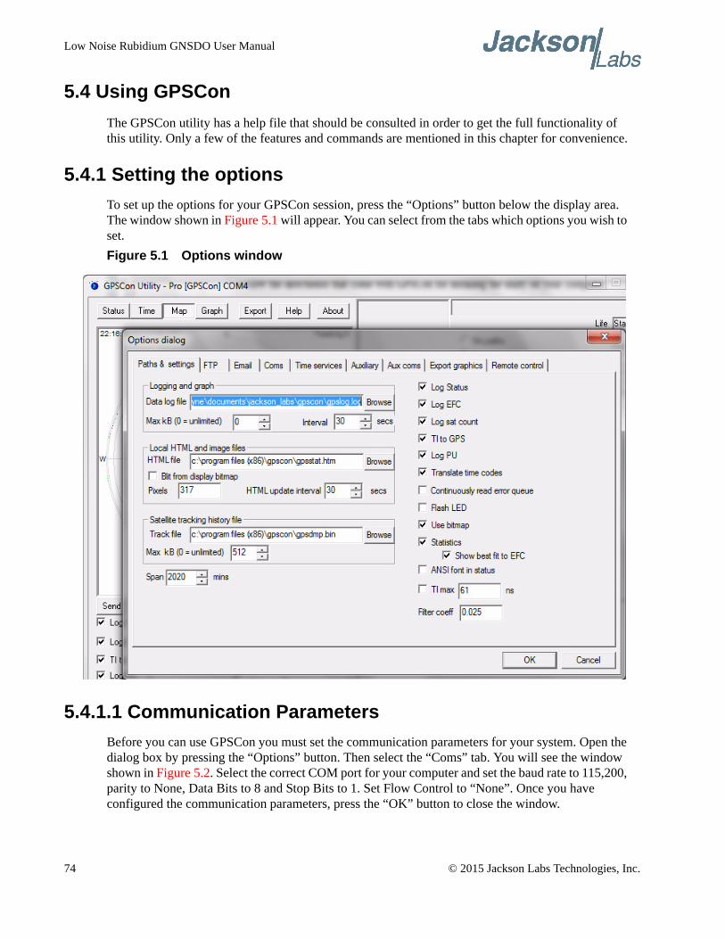
Low Noise Rubidium GNSDO User Manual
5.4 Using GPSCon
The GPSCon utility has a help file that should be consulted in order to get the full functionality of this utility. Only a few of the features and commands are mentioned in this chapter for convenience.
5.4.1 Setting the options
To set up the options for your GPSCon session, press the “Options” button below the display area. The window shown in Figure 5.1 will appear. You can select from the tabs which options you wish to set.
Figure 5.1 Options window
5.4.1.1 Communication Parameters
Before you can use GPSCon you must set the communication parameters for your system. Open the dialog box by pressing the “Options” button. Then select the “Coms” tab. You will see the window shown in Figure 5.2. Select the correct COM port for your computer and set the baud rate to 115,200, parity to None, Data Bits to 8 and Stop Bits to 1. Set Flow Control to “None”. Once you have configured the communication parameters, press the “OK” button to close the window.
74 © 2015 Jackson Labs Technologies, Inc.
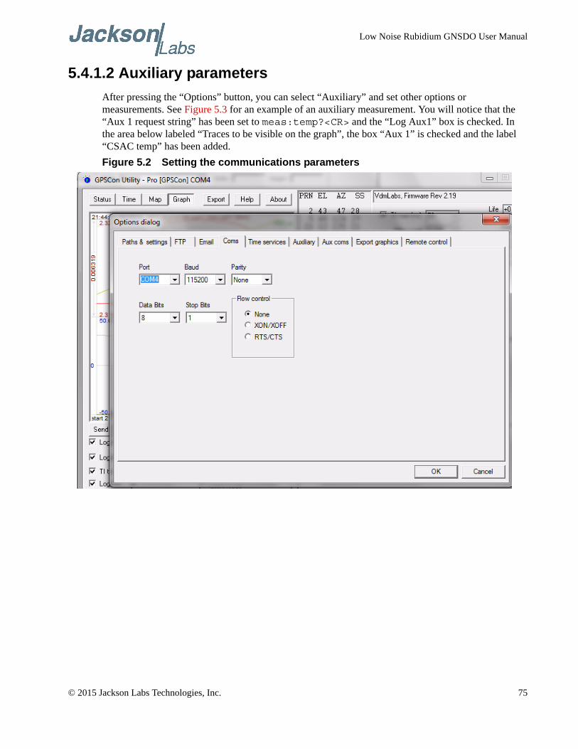
Low Noise Rubidium GNSDO User Manual
5.4.1.2 Auxiliary parameters
After pressing the “Options” button, you can select “Auxiliary” and set other options or measurements. See Figure 5.3 for an example of an auxiliary measurement. You will notice that the “Aux 1 request string” has been set to meas:temp?<CR> and the “Log Aux1” box is checked. In the area below labeled “Traces to be visible on the graph”, the box “Aux 1” is checked and the label “CSAC temp” has been added.
Figure 5.2 Setting the communications parameters
© 2015 Jackson Labs Technologies, Inc. 75
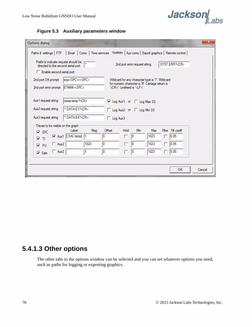
Low Noise Rubidium GNSDO User Manual
Figure 5.3 Auxiliary parameters window
5.4.1.3 Other options
The other tabs in the options window can be selected and you can set whatever options you need, such as paths for logging or exporting graphics.
76 © 2015 Jackson Labs Technologies, Inc.
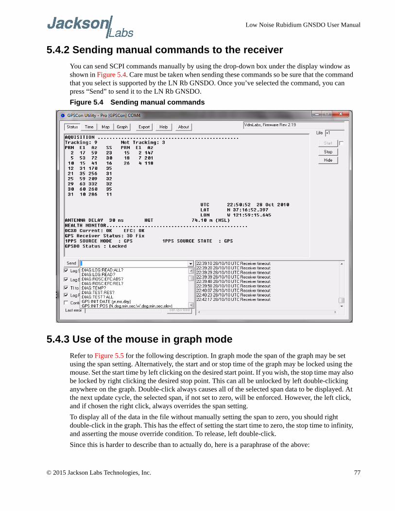
Low Noise Rubidium GNSDO User Manual
5.4.2 Sending manual commands to the receiver
You can send SCPI commands manually by using the drop-down box under the display window as shown in Figure 5.4. Care must be taken when sending these commands so be sure that the command that you select is supported by the LN Rb GNSDO. Once you’ve selected the command, you can press “Send” to send it to the LN Rb GNSDO.
Figure 5.4 Sending manual commands
5.4.3 Use of the mouse in graph mode
Refer to Figure 5.5 for the following description. In graph mode the span of the graph may be set using the span setting. Alternatively, the start and or stop time of the graph may be locked using the mouse. Set the start time by left clicking on the desired start point. If you wish, the stop time may also be locked by right clicking the desired stop point. This can all be unlocked by left double-clicking anywhere on the graph. Double-click always causes all of the selected span data to be displayed. At the next update cycle, the selected span, if not set to zero, will be enforced. However, the left click, and if chosen the right click, always overrides the span setting.
To display all of the data in the file without manually setting the span to zero, you should right double-click in the graph. This has the effect of setting the start time to zero, the stop time to infinity, and asserting the mouse override condition. To release, left double-click.
Since this is harder to describe than to actually do, here is a paraphrase of the above:
© 2015 Jackson Labs Technologies, Inc. 77

Low Noise Rubidium GNSDO User Manual
"To zoom in: The mouse is used to set the left extent and the right extent of the portion of the curve that the user wants to fill the screen. Click once with the left mouse button on the point that marks the left side of what you want to be the magnified curve. Immediately that point becomes the left end of the curve. Then similarly click the right mouse button on the curve at the time you wish to be the right most portion of the magnified curve and it immediately becomes the end point on the right side. And, finally to return to the zoomed out ("fit to window") view, left double-click on the curve."
Remember, in order to see all the data in the log file, you must either set the span control to zero, or right double-click in the graph.
When you have locked the start and stop time using the mouse, you can scroll left or right through the data without changing the span. To scroll to a later time, use Shift + Left click. To scroll to an earlier time, use Shift + Right click. Double left click to release everything.
The time span indication at the lower right of the graph will turn red to signify that mouse override is in effect.
Figure 5.5 Graph display
78 © 2015 Jackson Labs Technologies, Inc.
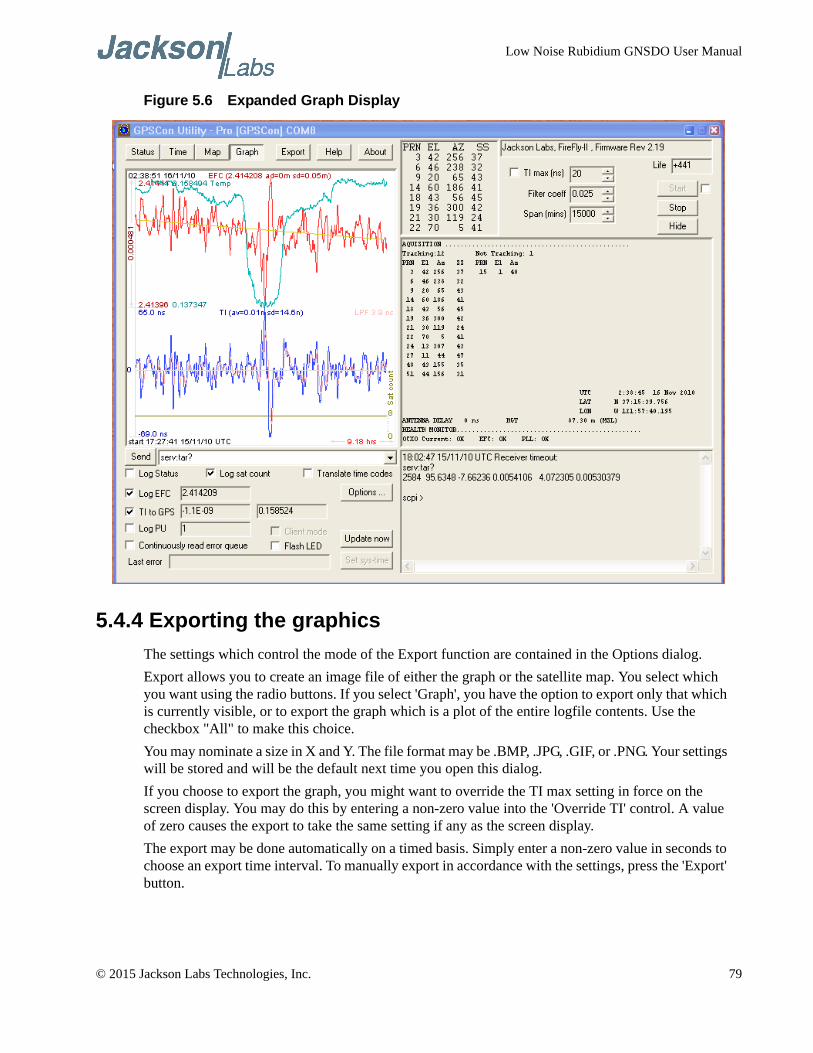
Low Noise Rubidium GNSDO User Manual
Figure 5.6 Expanded Graph Display
5.4.4 Exporting the graphics
The settings which control the mode of the Export function are contained in the Options dialog.
Export allows you to create an image file of either the graph or the satellite map. You select which you want using the radio buttons. If you select 'Graph', you have the option to export only that which is currently visible, or to export the graph which is a plot of the entire logfile contents. Use the checkbox "All" to make this choice.
You may nominate a size in X and Y. The file format may be .BMP, .JPG, .GIF, or .PNG. Your settings will be stored and will be the default next time you open this dialog.
If you choose to export the graph, you might want to override the TI max setting in force on the screen display. You may do this by entering a non-zero value into the 'Override TI' control. A value of zero causes the export to take the same setting if any as the screen display.
The export may be done automatically on a timed basis. Simply enter a non-zero value in seconds to choose an export time interval. To manually export in accordance with the settings, press the 'Export' button.
© 2015 Jackson Labs Technologies, Inc. 79
Low Noise Rubidium GNSDO User Manual
80 © 2015 Jackson Labs Technologies, Inc.

Low Noise Rubidium GNSDO User Manual
Certification and Warranty
6.1 Certification
Jackson Labs Technologies, Inc. certifies that this product met its published specifications at time of shipment.
6.1.1 Warranty
This Jackson Labs Technologies, Inc. hardware product is warranted against defects in material and workmanship for a period of 1 (one) year from date of delivery. During the warranty period Jackson Labs Technologies, Inc. will, at its discretion, either repair or replace products that prove to be defective. Jackson Labs Technologies, Inc. does not warrant that the operation for the software, firmware, or hardware shall be uninterrupted or error free even if the product is operated within its specifications.
For warranty service, this product must be returned to Jackson Labs Technologies, Inc. or a service facility designated by Jackson Labs Technologies, Inc. Customer shall prepay shipping charges (and shall pay all duties and taxes) for products returned to Jackson Labs Technologies, Inc. for warranty service. Except for products returned to Customer from another country, Jackson Labs Technologies, Inc. shall pay for return of products to Customer. If Jackson Labs Technologies, Inc. is unable, within a reasonable time, to repair or replace any product to condition as warranted, the Customer shall be entitled to a refund of the purchase price upon return of the product to Jackson Labs Technologies, Inc.
6.1.2 Limitation of Warranty
The foregoing warranty shall not apply to defects resulting from improper or inadequate maintenance by the Customer, Customer-supplied software or interfacing, unauthorized modification or misuse, opening of the instruments enclosure or removal of the instruments panels, operation outside of the environmental or electrical specifications for the product, or improper site preparation and maintenance. JACKSON LABS TECHNOLOGIES, INC. SPECIFICALLY DISCLAIMS THE IMPLIED WARRANTIES OF MERCHANTABILITY AND FITNESS FOR A PARTICULAR
© 2015 Jackson Labs Technologies, Inc. 81
Low Noise Rubidium GNSDO User Manual
PURPOSE. No license, express or implied, by estoppel or otherwise, to any intellectual property rights is granted by this document. Jackson Labs Technologies, Inc. products are not intended for use in medical, life saving, or life sustaining applications.
6.1.3 Exclusive Remedies
THE REMEDIES PROVIDED HEREIN ARE THE CUSTOMER'S SOLE AND EXCLUSIVE REMEDIES. JACKSON LABS TECHNOLOGIES, INC. SHALL NOT BE LIABLE FOR ANY DIRECT, INDIRECT, SPECIAL, INCIDENTAL, OR CONSEQUENTIAL DAMAGES, WHETHER BASED ON CONTRACT, TORT, OR ANY OTHER LEGAL THEORY.
82 © 2015 Jackson Labs Technologies, Inc.