GN Housing - Camfil Detailed Info/Literature (US... · GN Housing Camfil Farr Product ... Cleaning...
12
GN Housing Camfil Farr Product bulletin GN Housing 3405 - 0606 Camfil Farr—clean air solutions Camfil Farr GN Series Housings are designed for use in critical processes where hazardous airborne materials must be prevented from escaping to the atmosphere 1 . Although the Camfil Farr GN Housing is available in a basic configuration various options specific to the application are available. When matched with Camfil Farr Isolation Dampers, contaminated filters may be decontaminated before filter service. These housings are typically used in facilities that incorporate hazardous materials in their processes. These contaminants may include biomedical, radiological, carcinogenic or other materials of concern. Some specific applications include: Chemical manufacturing facilities Food processing Genetic research and biotechnology facilities Hospital Isolation Suites to prevent the spread of infectious diseases Industrial processes exhaust Microelectronic and semiconductor facilities Nuclear power plants Pharmaceutical facilities Radioisotope handling facilities University research laboratories US Department of Energy Facilities Veterinary research and animal disease laboratories Specific United States Government and military facilities. 1 If the user feels that a control barrier to protect changeout personnel is required the Camfil Farr GB Housing should be selected (see Camfil Farr Bulletin 3401). Gasket Seal Side-Access Non Bag-in/Bag-out Air Filter Housing Leakfree housing integrity to 15” w.g. with filter gasket sealing pressure up to 1400 pounds Top left: Filter locking tray assembly may apply up to 1400 pounds of filter sealing pressure. Top right: Pressure gauges may be added to housing to evaluate filter pressure drop. Bottom left: HEPA or ULPA filters, of various configurations are accepted by the housing. Bottom right: Installed gauges are hard-tubed for system integrity.
Transcript of GN Housing - Camfil Detailed Info/Literature (US... · GN Housing Camfil Farr Product ... Cleaning...

GN Housing
Camfil Farr Product bulletin
GN Housing 3405 - 0606
Camfil Farr—clean air solutions
Camfil Farr GN Series Housings are designed for use in critical processes where hazardous airborne materials must be prevented from escaping to the atmosphere
1.
Although the Camfil Farr GN Housing is available in a basic configuration various options specific to the application are available. When matched with Camfil Farr Isolation Dampers, contaminated filters may be decontaminated before filter service.
These housings are typically used in facilities that incorporate hazardous materials in their processes. These contaminants may include biomedical, radiological, carcinogenic or other materials of concern. Some specific applications include:
Chemical manufacturing facilities
Food processing
Genetic research and biotechnology facilities
Hospital Isolation Suites to prevent the spread of infectious diseases
Industrial processes exhaust
Microelectronic and semiconductor facilities
Nuclear power plants
Pharmaceutical facilities
Radioisotope handling facilities
University research laboratories
US Department of Energy Facilities
Veterinary research and animal disease laboratories
Specific United States Government and military facilities.
1 If the user feels that a control barrier to protect changeout personnel is required the Camfil Farr GB Housing should be selected (see Camfil Farr Bulletin 3401).
Gasket Seal Side-Access Non Bag-in/Bag-out Air Filter Housing
Leakfree housing integrity to 15” w.g. with filter gasket
sealing pressure up to 1400 pounds
Top left: Filter locking tray assembly may apply up to
1400 pounds of filter sealing pressure.
Top right: Pressure gauges may be added to housing to evaluate filter pressure drop.
Bottom left: HEPA or ULPA filters, of various
configurations are accepted by the housing.
Bottom right: Installed gauges are hard-tubed for
system integrity.
2
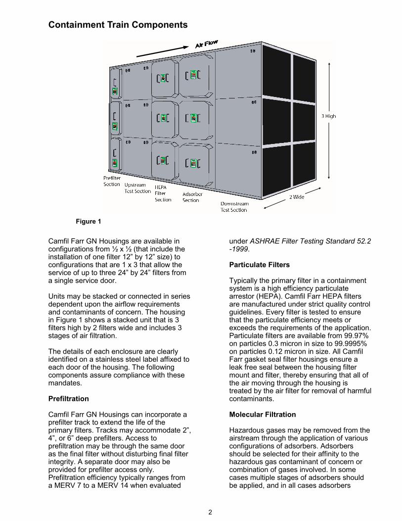
Camfil Farr GN Housings are available in configurations from ½ x ½ (that include the installation of one filter 12” by 12” size) to configurations that are 1 x 3 that allow the service of up to three 24” by 24” filters from a single service door. Units may be stacked or connected in series dependent upon the airflow requirements and contaminants of concern. The housing in Figure 1 shows a stacked unit that is 3 filters high by 2 filters wide and includes 3 stages of air filtration. The details of each enclosure are clearly identified on a stainless steel label affixed to each door of the housing. The following components assure compliance with these mandates. Prefiltration Camfil Farr GN Housings can incorporate a prefilter track to extend the life of the primary filters. Tracks may accommodate 2”, 4”, or 6” deep prefilters. Access to prefiltration may be through the same door as the final filter without disturbing final filter integrity. A separate door may also be provided for prefilter access only. Prefiltration efficiency typically ranges from a MERV 7 to a MERV 14 when evaluated
under ASHRAE Filter Testing Standard 52.2-1999. Particulate Filters Typically the primary filter in a containment system is a high efficiency particulate arrestor (HEPA). Camfil Farr HEPA filters are manufactured under strict quality control guidelines. Every filter is tested to ensure that the particulate efficiency meets or exceeds the requirements of the application. Particulate filters are available from 99.97% on particles 0.3 micron in size to 99.9995% on particles 0.12 micron in size. All Camfil Farr gasket seal filter housings ensure a leak free seal between the housing filter mount and filter, thereby ensuring that all of the air moving through the housing is treated by the air filter for removal of harmful contaminants. Molecular Filtration Hazardous gases may be removed from the airstream through the application of various configurations of adsorbers. Adsorbers should be selected for their affinity to the hazardous gas contaminant of concern or combination of gases involved. In some cases multiple stages of adsorbers should be applied, and in all cases adsorbers
Containment Train Components
Figure 1
3
should be prefiltered. An additional stage of prefiltration may be required downstream of the adsorber to capture any particulate that may be generated by the adsorber. Test Sections Most installations will require an in-place filter efficiency evaluation to ensure that the system is performing to specifications. Applications that should incorporate test sections include any system where access to upstream and downstream ductwork may be restricted. In-place test sections minimize system train distance requirements that are typical for proper mixing of challenge aerosol. In most cases the entire bank of air filters is evaluated for overall efficiency. Scan test sections are also available that allow individual filter scanning for leaks. Consult Camfil Bulletin 3407. CBR Systems (Special) A CBR system is a single filter system designed to control chemical, biological and radiological contaminants that may be generated by wartime, terrorist or industrial accident. The system usually includes prefiltration, HEPA filters, gaseous adsorbers and post filters for particulate removal in one certified leak free module. Contact factory for assistance with CBR units. Standard Component Construction Stainless Steel Construction Camfil Farr GN Housings are completely factory assembled and constructed of 304 stainless steel sheet metal. There are no painted surfaces, nor cross-contamination from the use of carbon/mild steel materials. Each housing is warranted to withstand 15” w.g. positive or negative pressure without failure of the housing to ambient air seal or compromise of the overall housing integrity. Each housing is tested to this level and test reports are available on request. Camfil Farr has the ability to custom design housing integrity to most operating conditions. Access Door (s) Access doors, of the same construction materials as the housing, include a high-memory silicone gasket that recreates a positive housing to ambient seal after each
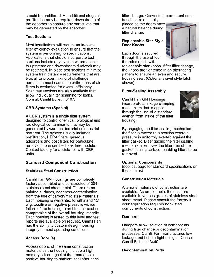
filter change. Convenient permanent door handles are optimally placed so the doors have a natural balance during filter change. Replaceable Star-Style Door Knobs Each door is secured through the use of four threaded studs with replaceable star knobs. After filter change, the knobs are tightened in an alternating pattern to ensure an even and secure housing seal. (Optional swivel style latch shown). Filter-Sealing Assembly Camfil Farr GN Housings incorporate a linkage clamping mechanism that is applied through the use of a standard wrench from inside of the filter housing. By engaging the filter sealing mechanism, the filter is moved to a position where a pressure is uniformly exerted against the filter gasket. Disengaging the filter sealing mechanism removes the filter free of the gasket sealing surface, enabling filters to be removed. Optional Components (see last page for standard specifications on these items) Construction Materials Alternate materials of construction are available. As an example, the units are available in various grades of stainless steel sheet metal. Please consult the factory if your application requires non-listed components of construction. Dampers Dampers allow isolation of components during filter change or decontamination processes. Camfil Farr manufactures low-leakage and bubble-tight designs. Consult Camfil Bulletins 3440. Decontamination Ports
4
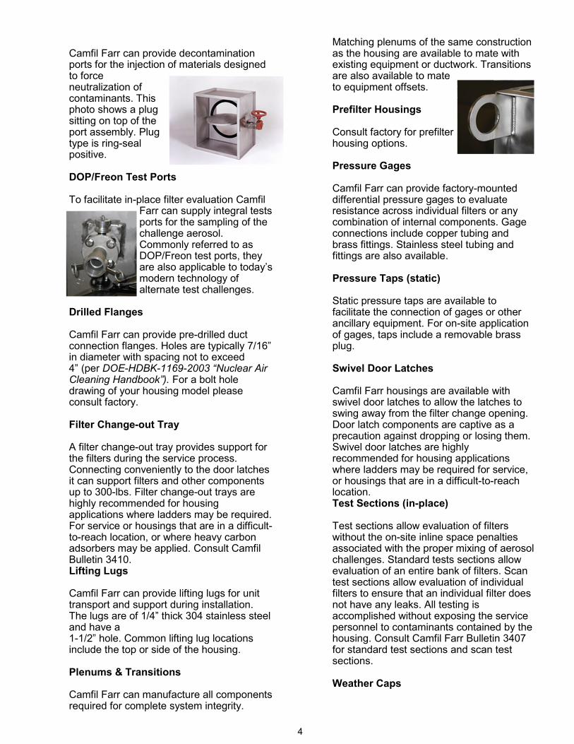
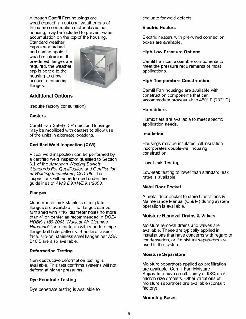
Camfil Farr can provide decontamination ports for the injection of materials designed to force neutralization of contaminants. This photo shows a plug sitting on top of the port assembly. Plug type is ring-seal positive. DOP/Freon Test Ports To facilitate in-place filter evaluation Camfil
Farr can supply integral tests ports for the sampling of the challenge aerosol. Commonly referred to as DOP/Freon test ports, they are also applicable to today’s modern technology of alternate test challenges.
Drilled Flanges Camfil Farr can provide pre-drilled duct connection flanges. Holes are typically 7/16” in diameter with spacing not to exceed 4” (per DOE-HDBK-1169-2003 “Nuclear Air Cleaning Handbook”). For a bolt hole drawing of your housing model please consult factory. Filter Change-out Tray A filter change-out tray provides support for the filters during the service process. Connecting conveniently to the door latches it can support filters and other components up to 300-lbs. Filter change-out trays are highly recommended for housing applications where ladders may be required. For service or housings that are in a difficult-to-reach location, or where heavy carbon adsorbers may be applied. Consult Camfil Bulletin 3410. Lifting Lugs Camfil Farr can provide lifting lugs for unit transport and support during installation. The lugs are of 1/4” thick 304 stainless steel and have a 1-1/2” hole. Common lifting lug locations include the top or side of the housing. Plenums & Transitions Camfil Farr can manufacture all components required for complete system integrity.
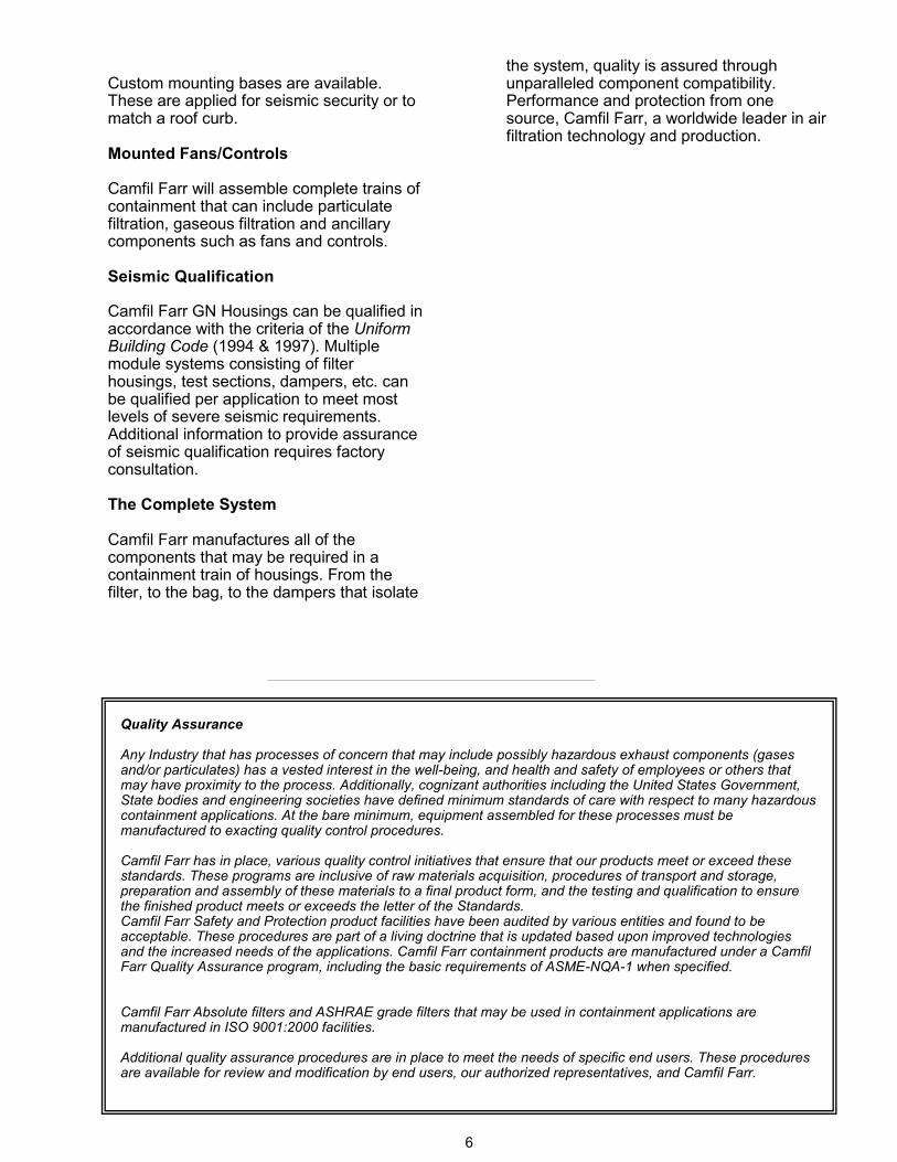
Matching plenums of the same construction as the housing are available to mate with existing equipment or ductwork. Transitions are also available to mate to equipment offsets. Prefilter Housings Consult factory for prefilter housing options. Pressure Gages Camfil Farr can provide factory-mounted differential pressure gages to evaluate resistance across individual filters or any combination of internal components. Gage connections include copper tubing and brass fittings. Stainless steel tubing and fittings are also available. Pressure Taps (static) Static pressure taps are available to facilitate the connection of gages or other ancillary equipment. For on-site application of gages, taps include a removable brass plug. Swivel Door Latches Camfil Farr housings are available with swivel door latches to allow the latches to swing away from the filter change opening. Door latch components are captive as a precaution against dropping or losing them. Swivel door latches are highly recommended for housing applications where ladders may be required for service, or housings that are in a difficult-to-reach location. Test Sections (in-place) Test sections allow evaluation of filters without the on-site inline space penalties associated with the proper mixing of aerosol challenges. Standard tests sections allow evaluation of an entire bank of filters. Scan test sections allow evaluation of individual filters to ensure that an individual filter does not have any leaks. All testing is accomplished without exposing the service personnel to contaminants contained by the housing. Consult Camfil Farr Bulletin 3407 for standard test sections and scan test sections. Weather Caps
5
Although Camfil Farr housings are weatherproof, an optional weather cap of the same construction materials as the housing, may be included to prevent water accumulation on the top of the housing. Standard weather caps are attached and sealed against weather intrusion. If pre-drilled flanges are required, the weather cap is bolted to the housing to allow access to mounting flanges. Additional Options (require factory consultation) Casters Camfil Farr Safety & Protection Housings may be mobilized with casters to allow use of the units in alternate locations. Certified Weld Inspection (CWI) Visual weld inspection can be performed by a certified weld inspector qualified to Section 6.1 of the American Welding Society Standards For Qualification and Certification of Welding Inspections, QC1-96. The inspections will be performed under the guidelines of AWS D9.1M/D9.1:2000. Flanges Quarter-inch thick stainless steel plate flanges are available. The flanges can be furnished with 7/16" diameter holes no more than 4" on center as recommended in DOE-HDBK-1169-2003 “Nuclear Air Cleaning Handbook” or to mate-up with standard pipe flange bolt hole patterns. Standard raised-face, slip-on, stainless steel flanges per ASA B16.5 are also available. Deformation Testing Non-destructive deformation testing is available. This test confirms systems will not deform at higher pressures. Dye Penetrate Testing Dye penetrate testing is available to
evaluate for weld defects. Electric Heaters Electric heaters with pre-wired connection boxes are available. High/Low Pressure Options Camfil Farr can assemble components to meet the pressure requirements of most applications. High-Temperature Construction Camfil Farr housings are available with construction components that can accommodate process air to 450° F (232° C). Humidifiers Humidifiers are available to meet specific application needs. Insulation Housings may be insulated. All insulation incorporates double-wall housing construction. Low Leak Testing Low-leak testing to lower than standard leak rates is available. Metal Door Pocket A metal door pocket to store Operations & Maintenance Manual (O & M) during system operation is available. Moisture Removal Drains & Valves Moisture removal drains and valves are available. These are typically applied in installations that have concerns with regard to condensation, or if moisture separators are used in the system. Moisture Separators Moisture separators applied as prefiltration are available. Camfil Farr Moisture Separators have an efficiency of 98% on 5-micron size droplets. Other variations of moisture separators are available (consult factory). Mounting Bases
6
Quality Assurance Any Industry that has processes of concern that may include possibly hazardous exhaust components (gases and/or particulates) has a vested interest in the well-being, and health and safety of employees or others that may have proximity to the process. Additionally, cognizant authorities including the United States Government, State bodies and engineering societies have defined minimum standards of care with respect to many hazardous containment applications. At the bare minimum, equipment assembled for these processes must be manufactured to exacting quality control procedures. Camfil Farr has in place, various quality control initiatives that ensure that our products meet or exceed these standards. These programs are inclusive of raw materials acquisition, procedures of transport and storage, preparation and assembly of these materials to a final product form, and the testing and qualification to ensure the finished product meets or exceeds the letter of the Standards. Camfil Farr Safety and Protection product facilities have been audited by various entities and found to be acceptable. These procedures are part of a living doctrine that is updated based upon improved technologies and the increased needs of the applications. Camfil Farr containment products are manufactured under a Camfil Farr Quality Assurance program, including the basic requirements of ASME-NQA-1 when specified. Camfil Farr Absolute filters and ASHRAE grade filters that may be used in containment applications are manufactured in ISO 9001:2000 facilities. Additional quality assurance procedures are in place to meet the needs of specific end users. These procedures are available for review and modification by end users, our authorized representatives, and Camfil Farr.
Custom mounting bases are available. These are applied for seismic security or to match a roof curb. Mounted Fans/Controls Camfil Farr will assemble complete trains of containment that can include particulate filtration, gaseous filtration and ancillary components such as fans and controls. Seismic Qualification Camfil Farr GN Housings can be qualified in accordance with the criteria of the Uniform Building Code (1994 & 1997). Multiple module systems consisting of filter housings, test sections, dampers, etc. can be qualified per application to meet most levels of severe seismic requirements. Additional information to provide assurance of seismic qualification requires factory consultation. The Complete System Camfil Farr manufactures all of the components that may be required in a containment train of housings. From the filter, to the bag, to the dampers that isolate
the system, quality is assured through unparalleled component compatibility. Performance and protection from one source, Camfil Farr, a worldwide leader in air filtration technology and production.
7
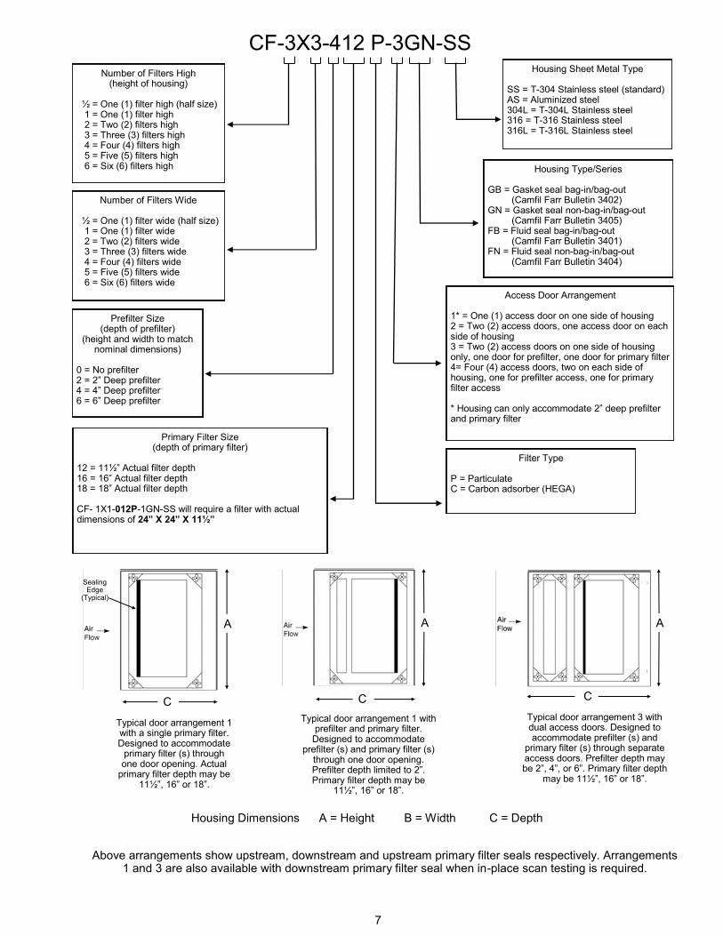
Number of Filters High (height of housing)
½ = One (1) filter high (half size) 1 = One (1) filter high 2 = Two (2) filters high 3 = Three (3) filters high 4 = Four (4) filters high 5 = Five (5) filters high 6 = Six (6) filters high
Number of Filters Wide
½ = One (1) filter wide (half size) 1 = One (1) filter wide 2 = Two (2) filters wide 3 = Three (3) filters wide 4 = Four (4) filters wide 5 = Five (5) filters wide 6 = Six (6) filters wide
Prefilter Size (depth of prefilter)
(height and width to match nominal dimensions)
0 = No prefilter 2 = 2” Deep prefilter 4 = 4” Deep prefilter 6 = 6” Deep prefilter
Primary Filter Size (depth of primary filter)
12 = 11½” Actual filter depth 16 = 16” Actual filter depth 18 = 18” Actual filter depth CF- 1X1-012P-1GN-SS will require a filter with actual dimensions of 24” X 24” X 11½”
Housing Sheet Metal Type SS = T-304 Stainless steel (standard) AS = Aluminized steel 304L = T-304L Stainless steel 316 = T-316 Stainless steel 316L = T-316L Stainless steel
Housing Type/Series GB = Gasket seal bag-in/bag-out (Camfil Farr Bulletin 3402) GN = Gasket seal non-bag-in/bag-out (Camfil Farr Bulletin 3405) FB = Fluid seal bag-in/bag-out (Camfil Farr Bulletin 3401) FN = Fluid seal non-bag-in/bag-out (Camfil Farr Bulletin 3404)
Access Door Arrangement 1* = One (1) access door on one side of housing 2 = Two (2) access doors, one access door on each side of housing 3 = Two (2) access doors on one side of housing only, one door for prefilter, one door for primary filter 4= Four (4) access doors, two on each side of housing, one for prefilter access, one for primary filter access * Housing can only accommodate 2” deep prefilter and primary filter
Filter Type P = Particulate C = Carbon adsorber (HEGA)
CF-3X3-412 P-3GN-SS
Typical door arrangement 1 with a single primary filter. Designed to accommodate
primary filter (s) through one door opening. Actual
primary filter depth may be 11½”, 16” or 18”.
Typical door arrangement 1 with prefilter and primary filter.
Designed to accommodate prefilter (s) and primary filter (s)
through one door opening. Prefilter depth limited to 2”. Primary filter depth may be
11½”, 16” or 18”.
Typical door arrangement 3 with dual access doors. Designed to accommodate prefilter (s) and
primary filter (s) through separate access doors. Prefilter depth may be 2”, 4”, or 6”. Primary filter depth
may be 11½”, 16” or 18”.
Above arrangements show upstream, downstream and upstream primary filter seals respectively. Arrangements 1 and 3 are also available with downstream primary filter seal when in-place scan testing is required.
A A A
C C C
Housing Dimensions A = Height B = Width C = Depth
Sealing Edge
(Typical)

8
Housing Size/Configuration Chart - 012-1GN
Housing Size
(H x W)
Prefilter Depth
(inches)
Primary Filter Depth
(inches)
Door Arrangement
Dimension A
(inches)
Dimension B
(inches)
Shipping Weight
(lbs)
Dimension C
(inches)
½ x ½ N/A 12 1 18 15 125 26
½ x 1 N/A 12 1 18 27 165 26
1 x 1 N/A 12 1 30 27 198 26
1 x 2 N/A 12 1 30 51 305 26
1 x 3 N/A 12 1 30 75 410 26
2 x 1 N/A 12 1 60 27 350 26
2 x 2 N/A 12 1 60 51 540 26
2 x 3 N/A 12 1 60 75 720 26
3 x 1 N/A 12 1 90 27 500 26
3 x 2 N/A 12 1 90 51 770 26
3 x 3 N/A 12 1 90 75 1030 26
4 x 1 N/A 12 1 120 27 650 26
4 x 2 N/A 12 1 120 51 1000 26
4 x 3 N/A 12 1 120 75 1335 26
Housing Size/Configuration Chart - 018-1GN
Housing Size
(H x W)
Prefilter Depth
(inches)
Primary Filter Depth
(inches)
Door Arrangement
Dimension A
(inches)
Dimension B
(inches)
Shipping Weight
(lbs)
Dimension C
(inches)
½ x ½ N/A 18 1 18 15 145 33
½ x 1 N/A 18 1 18 27 195 33
1 x 1 N/A 18 1 30 27 230 33
1 x 2 N/A 18 1 30 51 350 33
1 x 3 N/A 18 1 30 75 470 33
2 x 1 N/A 18 1 60 27 400 33
2 x 2 N/A 18 1 60 51 615 33
2 x 3 N/A 18 1 60 75 820 33
3 x 1 N/A 18 1 90 27 615 33
3 x 2 N/A 18 1 90 51 575 33
3 x 3 N/A 18 1 90 75 1165 33
4 x 1 N/A 18 1 120 27 750 33
4 x 2 N/A 18 1 120 51 1140 33
4 x 3 N/A 18 1 120 75 1510 33
Housing Size/Configuration Chart - 016-1GN
Housing Size
(H x W)
Prefilter Depth
(inches)
Primary Filter Depth
(inches)
Door Arrangement
Dimension A
(inches)
Dimension B
(inches)
Shipping Weight
(lbs)
Dimension C
(inches)
½ x ½ N/A 16 1 18 15 135 30
½ x 1 N/A 16 1 18 27 180 30
1 x 1 N/A 16 1 30 27 215 30
1 x 2 N/A 16 1 30 51 330 30
1 x 3 N/A 16 1 30 75 445 30
2 x 1 N/A 16 1 60 27 380 30
2 x 2 N/A 16 1 60 51 580 30
2 x 3 N/A 16 1 60 75 780 30
3 x 1 N/A 16 1 90 27 545 30
3 x 2 N/A 16 1 90 51 830 30
3 x 3 N/A 16 1 90 75 1110 30
4 x 1 N/A 16 1 120 27 710 30
4 x 2 N/A 16 1 120 51 1080 30
4 x 3 N/A 16 1 120 75 1440 30
Continued on next page.
A
B B B
C
1 high by 3 wide 1 high by 1 wide with prefilter section. Left Hand Access Right Hand Access
A
A
C
A
B C C
9
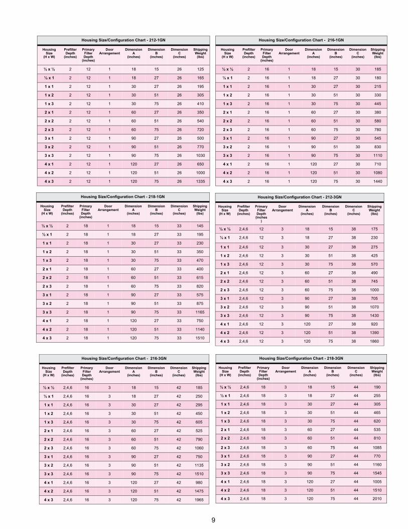
Housing Size/Configuration Chart - 218-3GN
Housing Size
(H x W)
Prefilter Depth
(inches)
Primary Filter Depth
(inches)
Door Arrangement
Dimension A
(inches)
Dimension B
(inches)
Shipping Weight
(lbs)
Dimension C
(inches)
½ x ½ 2,4,6 18 3 18 15 190 44
½ x 1 2,4,6 18 3 18 27 255 44
1 x 1 2,4,6 18 3 30 27 305 44
1 x 2 2,4,6 18 3 30 51 465 44
1 x 3 2,4,6 18 3 30 75 620 44
2 x 1 2,4,6 18 3 60 27 535 44
2 x 2 2,4,6 18 3 60 51 810 44
2 x 3 2,4,6 18 3 60 75 1085 44
3 x 1 2,4,6 18 3 90 27 770 44
3 x 2 2,4,6 18 3 90 51 1160 44
3 x 3 2,4,6 18 3 90 75 1545 44
4 x 1 2,4,6 18 3 120 27 1005 44
4 x 2 2,4,6 18 3 120 51 1510 44
4 x 3 2,4,6 18 3 120 75 2010 44
Housing Size/Configuration Chart - 216-3GN
Housing Size
(H x W)
Prefilter Depth
(inches)
Primary Filter Depth
(inches)
Door Arrangement
Dimension A
(inches)
Dimension B
(inches)
Shipping Weight
(lbs)
Dimension C
(inches)
½ x ½ 2,4,6 16 3 18 15 185 42
½ x 1 2,4,6 16 3 18 27 250 42
1 x 1 2,4,6 16 3 30 27 295 42
1 x 2 2,4,6 16 3 30 51 450 42
1 x 3 2,4,6 16 3 30 75 605 42
2 x 1 2,4,6 16 3 60 27 525 42
2 x 2 2,4,6 16 3 60 51 790 42
2 x 3 2,4,6 16 3 60 75 1060 42
3 x 1 2,4,6 16 3 90 27 750 42
3 x 2 2,4,6 16 3 90 51 1135 42
3 x 3 2,4,6 16 3 90 75 1510 42
4 x 1 2,4,6 16 3 120 27 980 42
4 x 2 2,4,6 16 3 120 51 1475 42
4 x 3 2,4,6 16 3 120 75 1965 42
Housing Size/Configuration Chart - 212-3GN
Housing Size
(H x W)
Prefilter Depth
(inches)
Primary Filter Depth
(inches)
Door Arrangement
Dimension A
(inches)
Dimension B
(inches)
Shipping Weight
(lbs)
Dimension C
(inches)
½ x ½ 2,4,6 12 3 18 15 175 38
½ x 1 2,4,6 12 3 18 27 230 38
1 x 1 2,4,6 12 3 30 27 275 38
1 x 2 2,4,6 12 3 30 51 425 38
1 x 3 2,4,6 12 3 30 75 570 38
2 x 1 2,4,6 12 3 60 27 490 38
2 x 2 2,4,6 12 3 60 51 745 38
2 x 3 2,4,6 12 3 60 75 1000 38
3 x 1 2,4,6 12 3 90 27 705 38
3 x 2 2,4,6 12 3 90 51 1070 38
3 x 3 2,4,6 12 3 90 75 1430 38
4 x 1 2,4,6 12 3 120 27 920 38
4 x 2 2,4,6 12 3 120 51 1390 38
4 x 3 2,4,6 12 3 120 75 1860 38
Housing Size/Configuration Chart - 218-1GN
Housing Size
(H x W)
Prefilter Depth
(inches)
Primary Filter Depth
(inches)
Door Arrangement
Dimension A
(inches)
Dimension B
(inches)
Shipping Weight
(lbs)
Dimension C
(inches)
½ x ½ 2 18 1 18 15 145 33
½ x 1 2 18 1 18 27 195 33
1 x 1 2 18 1 30 27 230 33
1 x 2 2 18 1 30 51 350 33
1 x 3 2 18 1 30 75 470 33
2 x 1 2 18 1 60 27 400 33
2 x 2 2 18 1 60 51 615 33
2 x 3 2 18 1 60 75 820 33
3 x 1 2 18 1 90 27 575 33
3 x 2 2 18 1 90 51 875 33
3 x 3 2 18 1 90 75 1165 33
4 x 1 2 18 1 120 27 750 33
4 x 2 2 18 1 120 51 1140 33
4 x 3 2 18 1 120 75 1510 33
Housing Size/Configuration Chart - 216-1GN
Housing Size
(H x W)
Prefilter Depth
(inches)
Primary Filter Depth
(inches)
Door Arrangement
Dimension A
(inches)
Dimension B
(inches)
Shipping Weight
(lbs)
Dimension C
(inches)
½ x ½ 2 16 1 18 15 185 30
½ x 1 2 16 1 18 27 180 30
1 x 1 2 16 1 30 27 215 30
1 x 2 2 16 1 30 51 330 30
1 x 3 2 16 1 30 75 445 30
2 x 1 2 16 1 60 27 380 30
2 x 2 2 16 1 60 51 580 30
2 x 3 2 16 1 60 75 780 30
3 x 1 2 16 1 90 27 545 30
3 x 2 2 16 1 90 51 830 30
3 x 3 2 16 1 90 75 1110 30
4 x 1 2 16 1 120 27 710 30
4 x 2 2 16 1 120 51 1080 30
4 x 3 2 16 1 120 75 1440 30
Housing Size/Configuration Chart - 212-1GN
Housing Size
(H x W)
Prefilter Depth
(inches)
Primary Filter Depth
(inches)
Door Arrangement
Dimension A
(inches)
Dimension B
(inches)
Shipping Weight
(lbs)
Dimension C
(inches)
½ x ½ 2 12 1 18 15 125 26
½ x 1 2 12 1 18 27 165 26
1 x 1 2 12 1 30 27 195 26
1 x 2 2 12 1 30 51 305 26
1 x 3 2 12 1 30 75 410 26
2 x 1 2 12 1 60 27 350 26
2 x 2 2 12 1 60 51 540 26
2 x 3 2 12 1 60 75 720 26
3 x 1 2 12 1 90 27 500 26
3 x 2 2 12 1 90 51 770 26
3 x 3 2 12 1 90 75 1030 26
4 x 1 2 12 1 120 27 650 26
4 x 2 2 12 1 120 51 1000 26
4 x 3 2 12 1 120 75 1335 26
10
1.0 – General
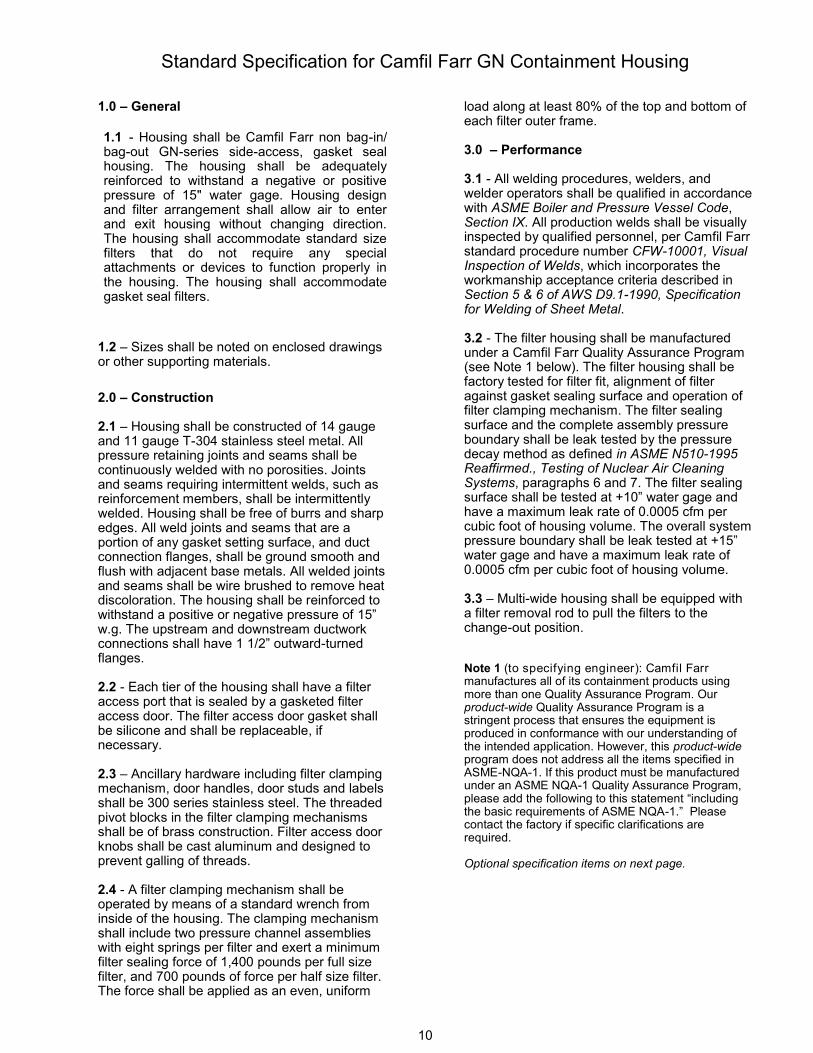
1.1 - Housing shall be Camfil Farr non bag-in/bag-out GN-series side-access, gasket seal housing. The housing shall be adequately reinforced to withstand a negative or positive pressure of 15" water gage. Housing design and filter arrangement shall allow air to enter and exit housing without changing direction. The housing shall accommodate standard size filters that do not require any special attachments or devices to function properly in the housing. The housing shall accommodate gasket seal filters.
1.2 – Sizes shall be noted on enclosed drawings or other supporting materials.
2.0 – Construction 2.1 – Housing shall be constructed of 14 gauge and 11 gauge T-304 stainless steel metal. All pressure retaining joints and seams shall be continuously welded with no porosities. Joints and seams requiring intermittent welds, such as reinforcement members, shall be intermittently welded. Housing shall be free of burrs and sharp edges. All weld joints and seams that are a portion of any gasket setting surface, and duct connection flanges, shall be ground smooth and flush with adjacent base metals. All welded joints and seams shall be wire brushed to remove heat discoloration. The housing shall be reinforced to withstand a positive or negative pressure of 15” w.g. The upstream and downstream ductwork connections shall have 1 1/2” outward-turned flanges. 2.2 - Each tier of the housing shall have a filter access port that is sealed by a gasketed filter access door. The filter access door gasket shall be silicone and shall be replaceable, if necessary. 2.3 – Ancillary hardware including filter clamping mechanism, door handles, door studs and labels shall be 300 series stainless steel. The threaded pivot blocks in the filter clamping mechanisms shall be of brass construction. Filter access door knobs shall be cast aluminum and designed to prevent galling of threads.
2.4 - A filter clamping mechanism shall be operated by means of a standard wrench from inside of the housing. The clamping mechanism shall include two pressure channel assemblies with eight springs per filter and exert a minimum filter sealing force of 1,400 pounds per full size filter, and 700 pounds of force per half size filter. The force shall be applied as an even, uniform
load along at least 80% of the top and bottom of each filter outer frame. 3.0 – Performance 3.1 - All welding procedures, welders, and welder operators shall be qualified in accordance with ASME Boiler and Pressure Vessel Code, Section IX. All production welds shall be visually inspected by qualified personnel, per Camfil Farr standard procedure number CFW-10001, Visual Inspection of Welds, which incorporates the workmanship acceptance criteria described in Section 5 & 6 of AWS D9.1-1990, Specification for Welding of Sheet Metal. 3.2 - The filter housing shall be manufactured under a Camfil Farr Quality Assurance Program (see Note 1 below). The filter housing shall be factory tested for filter fit, alignment of filter against gasket sealing surface and operation of filter clamping mechanism. The filter sealing surface and the complete assembly pressure boundary shall be leak tested by the pressure decay method as defined in ASME N510-1995 Reaffirmed., Testing of Nuclear Air Cleaning Systems, paragraphs 6 and 7. The filter sealing surface shall be tested at +10” water gage and have a maximum leak rate of 0.0005 cfm per cubic foot of housing volume. The overall system pressure boundary shall be leak tested at +15” water gage and have a maximum leak rate of 0.0005 cfm per cubic foot of housing volume. 3.3 – Multi-wide housing shall be equipped with a filter removal rod to pull the filters to the change-out position. Note 1 (to specifying engineer): Camfil Farr manufactures all of its containment products using more than one Quality Assurance Program. Our product-wide Quality Assurance Program is a stringent process that ensures the equipment is produced in conformance with our understanding of the intended application. However, this product-wide program does not address all the items specified in ASME-NQA-1. If this product must be manufactured under an ASME NQA-1 Quality Assurance Program, please add the following to this statement “including the basic requirements of ASME NQA-1.” Please contact the factory if specific clarifications are required. Optional specification items on next page.
Standard Specification for Camfil Farr GN Containment Housing

11
Optional Specification Items
The format of these additional specification items includes a section numbering system consistent with today’s requirements. Items beginning with the numeral 1 relate to general items, numeral 2 for construction components, and 3 for performance criterion. Dependent upon the option there may be an addition to one or more specification sections. Replace the # with a proper sequencing number based upon options selected. Decontamination Ports 2.# - Housing shall be provided with decontamination ports for injection of materials to neutralize contaminants. (Specify details. Contact factory for assistance). DOP/Freon Test Port 2.# - Challenge aerosol sampling ports shall be provided upstream and downstream of each primary filter access door. The port shall be 3/8” FIPS and include a hex head brass plug for periods when it is not in use. Drilled Duct Connection Flanges 2.# - Housing shall include pre-drilled flanges to facilitate attachment to ductwork. Holes shall be 7/16-inch diameter with spacing between holes not to exceed 4” as recommended in DOE-HDBK-1169-2003 “Nuclear Air Cleaning Handbook”. Filter Change-out Tray 2.# - A filter change-out tray of stainless steel welded construction shall be provided. The tray shall be designed for attachment to door studs during filter change. The tray shall be capable of supporting 300 pounds. (Specify quantity required). Lifting Lugs 2.# - Lifting lugs, constructed of 1/4-inch thick Type 304 stainless steel shall be provided on the (side, top) of the housing. The lugs shall be capable of supporting the housing without housing deflection during transport and installation. Prefilter Housings Consult factory. Factory-Mounted Pressure Gages
2.# - Housing shall include factory mounted pressure gages to measure any combination of pressure drop across prefiltration, final filtration, or combination thereof (specify requirements). Gage increments shall be as noted on enclosed drawings or other supporting materials. Gage tubing shall be copper construction with brass compression fittings. Pressure Taps (static) 2.# - Static pressure taps with 1/4-inch FIPS threads that allow field installation of static measurement gages or other measurement devices shall be included upstream and downstream of filter stages. Taps shall allow measurement across (prefilter only, prefilter and primary filter system, primary filter only, or overall systems including multiple prefilter and primary filter combinations). (Specify requirements). Swivel Door Latches 2.# - Housings shall be equipped with swivel door latches that shall completely swing-away from the filter change opening. All latching components shall remain captive during change. Test Sections Consult factory for test section options. Weather Cap 2.# - Housing shall be provided with a weather cap that shall promote moisture run-off and prevent moisture accumulation on the top of the containment housing. The weather cap shall be constructed of the same materials as the housing and shall be intermittently welded and sealed against weather intrusion, bolted to the housing to allow access to housing mounting flanges.

12
Camfil Farr, Inc. Washington NC Tel: (252) 975-1141 Fax: (252) 975-1041 Corporate Locations: United States Tel: (973) 616-7300 Fax: (973) 616-7771 Canada Tel: (450) 629-3030 Fax: (450) 662-6035 E-mail: [email protected]
© Camfil Farr http://www.camfilfarr.info http://www.camfilfarr.com
Camfil Farr has a policy of uninterrupted research, development and product improvement. We reserve the right to change designs and specifications without notice.