GMSS92 / GCSS92 - Manchester Total Air Supply · SS-GMSS92 9/14 GMSS92 / GCSS92 HeatinG input:...
12
SS-GMSS92 www.goodmanmfg.com 9/14 GMSS92 / GCSS92 HEATING INPUT: 40,000–120,000 BTU/H Contents Nomenclature ........................................... 2 Product Specifications .............................. 3 Dimensions ............................................... 5 Airflow Specifications................................ 7 Wiring Diagram....................................... 10 Accessories .............................................. 11 SINGLE-STAGE MULTI-SPEED GAS FURNACE UP TO 92% AFUE Standard Features • Heavy-duty stainless-steel tubular heat exchanger • Stainless-steel secondary heat exchanger • Single-stage gas valve • Durable Silicon Nitride igniter • Multi-speed blower motor • Quiet single-speed induced draft blower • Self-diagnostic control board • Color-coded low-voltage terminals • All models comply with California Low NOx emissions standards Cabinet Features • Designed for multi-position installation — GMSS92: upflow, horizontal left or right GCSS92: downflow, horizontal left or right • Certified for direct vent (2-pipe) or non-direct vent (1-pipe) • Easy-to-install top venting with optional side venting • Convenient left or right connection for gas and electrical service • Cabinet air leakage (Q Leak ) ≤ 2% • Heavy-gauge steel cabinet with durable finish • Foil-faced insulated heat exchanger cabinet • Airtight solid bottom or side return with easy-cut tabs for effortless removal in bottom air-inlet applications * Complete warranty details available from your local dealer or at www.goodmanmfg.com. To receive the Lifetime Heat Exchanger Limited Warranty (good for as long as you own your home), and 10-Year Parts Limited Warranty, online registration must be completed within 60 days of installation. Online registration is not required in California or Québec.
Transcript of GMSS92 / GCSS92 - Manchester Total Air Supply · SS-GMSS92 9/14 GMSS92 / GCSS92 HeatinG input:...

SS-GMSS92 www.goodmanmfg.com 9/14
GMSS92 / GCSS92
HeatinG input: 40,000–120,000 Btu/H
ContentsNomenclature ...........................................2Product Specifications ..............................3Dimensions ...............................................5Airflow Specifications ................................ 7Wiring Diagram .......................................10Accessories .............................................. 11
SinGle-StaGe Multi-Speed GaS FurnaCe
up to 92% aFue
Standard Features• Heavy-duty stainless-steel tubular heat exchanger • Stainless-steel secondary heat exchanger• Single-stage gas valve• Durable Silicon Nitride igniter• Multi-speed blower motor• Quiet single-speed induced draft blower• Self-diagnostic control board • Color-coded low-voltage terminals • All models comply with California Low NOx
emissions standards
Cabinet Features• Designed for multi-position installation —
GMSS92: upflow, horizontal left or right GCSS92: downflow, horizontal left or right
• Certified for direct vent (2-pipe) or non-direct vent (1-pipe)
• Easy-to-install top venting with optional side venting
• Convenient left or right connection for gas and electrical service
• Cabinet air leakage (QLeak) ≤ 2% • Heavy-gauge steel cabinet with durable finish• Foil-faced insulated heat exchanger cabinet• Airtight solid bottom or side return with
easy-cut tabs for effortless removal in bottom air-inlet applications
* Complete warranty details available from your local dealer or at www.goodmanmfg.com. To receive the Lifetime Heat Exchanger Limited Warranty (good for as long as you own your home), and 10-Year Parts Limited Warranty, online registration must be completed within 60 days of installation. Online registration is not required in California or Québec.

Product SPecificationS
2 www.goodmanmfg.com SS-GMSS92 SS-GMSS92 www.goodmanmfg.com 3
noMenClature
G M S S 92 040 3 B N A A1 2 3 4 5,6 7,8,9 10 11 12 13 14
Brand Minor RevisionG -‐ Goodman A -‐ Initial Release
B -‐ 1st RevisionConfigurationM -‐ Upflow/Horizontal Major RevisionC -‐ Downflow/Horizontal A -‐ Initial Release
B -‐ 1st RevisionMotorV -‐ Variable Speed ECM / ComfortNet NOxE -‐ Multi-‐Speed ECM N -‐ Low NOxS -‐ Single Speed
Cabinet WidthGas Valve B -‐ 17.5"M -‐ Modulating C -‐ 21"C -‐ 2 Stage D -‐ 24.5"S -‐ Single Stage
AFUE Maximum CFM92 -‐ 92% AFUE 2 -‐ 800 CFM96 -‐ 96% AFUE 3 -‐ 1200 CFM97 -‐ 97% AFUE 4 -‐ 1600 CFM
5 -‐ 2000 CFMMBTU/h040 -‐ 40,000 BTU/h060 -‐ 60,000 BTU/h120 -‐ 120,000 BTU/h
Product SPecificationS
2 www.goodmanmfg.com SS-GMSS92 SS-GMSS92 www.goodmanmfg.com 3
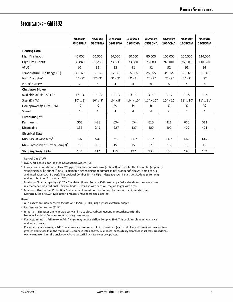
SpeCiFiCationS - GMSS92
GMSS92 0402BNA
GMSS920603BNA
GMSS920803BNA
GMSS920804CNA
GMSS920805CNA
GMSS921004CNA
GMSS921005CNA
GMSS921205DNA
Heating DataHigh Fire Input¹ 40,000 60,000 80,000 80,000 80,000 100,000 100,000 120,000
High Fire Output¹ 36,840 55,260 73,680 73,680 73,680 92,100 92,100 110,520
AFUE² 92 92 92 92 92 92 92 92
Temperature Rise Range (°F) 30 - 60 35 - 65 35 - 65 35 - 65 25 - 55 35 - 65 35 - 65 35 - 65
Vent Diameter³ 2" - 3" 2" - 3" 2" - 3" 2" - 3" 2" - 3" 2" - 3" 2" - 3" 3"No. of Burners 2 3 4 4 4 5 5 6
Circulator BlowerAvailable AC @ 0.5" ESP 1.5 - 3 1.5 - 3 1.5 - 3 3 - 5 3 - 5 3 - 5 3 - 5 3 - 5
Size (D x W) 10" x 8" 10" x 8" 10" x 8" 10" x 10" 11" x 10" 10" x 10" 11" x 10" 11" x 11"
Horsepower @ 1075 RPM ⅓ ⅓ ⅓ ½ ¾ ½ ¾ ¾Speed 4 4 4 4 4 4 4 4
Filter Size (in²)Permanent 363 491 654 654 818 818 818 981Disposable 182 245 327 327 409 409 409 491
Electrical DataMin. Circuit Ampacity⁴ 9.6 9.6 9.6 11.7 13.7 11.7 13.7 13.7
Max. Overcurrent Device (amps)⁵ 15 15 15 15 15 15 15 15
Shipping Weight (lbs) 109 112 115 137 138 139 140 152
¹ Natural Gas BTU/h² DOE AFUE based upon Isolated Combustion System (ICS)³ Installer must supply one or two PVC pipes: one for combustion air (optional) and one for the flue outlet (required).
Vent pipe must be either 2" or 3" in diameter, depending upon furnace input, number of elbows, length of run and installation (1 or 2 pipes). The optional Combustion Air Pipe is dependent on installation/code requirements and must be 2" or 3" diameter PVC.
⁴ Minimum Circuit Ampacity = (1.25 x Circulator Blower Amps) + ID Blower amps. Wire size should be determined in accordance with National Electrical Codes. Extensive wire runs will require larger wire sizes.
⁵ Maximum Overcurrent Protection Device refers to maximum recommended fuse or circuit breaker size. May use fuses or HACR-type circuit breakers of the same size as noted.
Notes• All furnaces are manufactured for use on 115 VAC, 60 Hz, single-phase electrical supply.• Gas Service Connection ½" FPT• Important: Size fuses and wires properly and make electrical connections in accordance with the
National Electrical Code and/or all existing local codes.• For bottom return: Failure to unfold flanges may reduce airflow by up to 18%. This could result in performance
and noise issues.• For servicing or cleaning, a 24" front clearance is required. Unit connections (electrical, flue and drain) may necessitate
greater clearances than the minimum clearances listed above. In all cases, accessibility clearance must take precedence over clearances from the enclosure where accessibility clearances are greater.
Product SPecificationS
4 www.goodmanmfg.com SS-GMSS92 SS-GMSS92 www.goodmanmfg.com 5
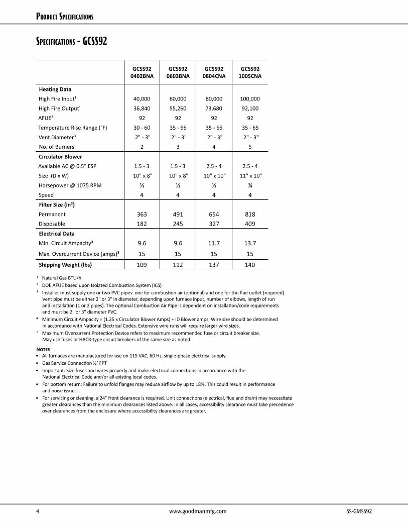
SpeCiFiCationS - GCSS92
¹ Natural Gas BTU/h² DOE AFUE based upon Isolated Combustion System (ICS)³ Installer must supply one or two PVC pipes: one for combustion air (optional) and one for the flue outlet (required).
Vent pipe must be either 2" or 3" in diameter, depending upon furnace input, number of elbows, length of run and installation (1 or 2 pipes). The optional Combustion Air Pipe is dependent on installation/code requirements and must be 2" or 3" diameter PVC.
⁴ Minimum Circuit Ampacity = (1.25 x Circulator Blower Amps) + ID Blower amps. Wire size should be determined in accordance with National Electrical Codes. Extensive wire runs will require larger wire sizes.
⁵ Maximum Overcurrent Protection Device refers to maximum recommended fuse or circuit breaker size. May use fuses or HACR-type circuit breakers of the same size as noted.
Notes• All furnaces are manufactured for use on 115 VAC, 60 Hz, single-phase electrical supply.• Gas Service Connection ½" FPT• Important: Size fuses and wires properly and make electrical connections in accordance with the
National Electrical Code and/or all existing local codes.• For bottom return: Failure to unfold flanges may reduce airflow by up to 18%. This could result in performance
and noise issues.• For servicing or cleaning, a 24" front clearance is required. Unit connections (electrical, flue and drain) may necessitate
greater clearances than the minimum clearances listed above. In all cases, accessibility clearance must take precedence over clearances from the enclosure where accessibility clearances are greater.
GCSS92 0402BNA
GCSS920603BNA
GCSS920804CNA
GCSS921005CNA
Heating DataHigh Fire Input¹ 40,000 60,000 80,000 100,000
High Fire Output¹ 36,840 55,260 73,680 92,100
AFUE² 92 92 92 92
Temperature Rise Range (°F) 30 - 60 35 - 65 35 - 65 35 - 65
Vent Diameter³ 2" - 3" 2" - 3" 2" - 3" 2" - 3"No. of Burners 2 3 4 5
Circulator BlowerAvailable AC @ 0.5" ESP 1.5 - 3 1.5 - 3 2.5 - 4 2.5 - 4
Size (D x W) 10" x 8" 10" x 8" 10" x 10" 11" x 10"
Horsepower @ 1075 RPM ⅓ ⅓ ½ ¾Speed 4 4 4 4Filter Size (in²)Permanent 363 491 654 818Disposable 182 245 327 409Electrical DataMin. Circuit Ampacity⁴ 9.6 9.6 11.7 13.7Max. Overcurrent Device (amps)⁵ 15 15 15 15
Shipping Weight (lbs) 109 112 137 140

Product SPecificationS
4 www.goodmanmfg.com SS-GMSS92 SS-GMSS92 www.goodmanmfg.com 5
GMSS92 diMenSionS
MiniMuM ClearanCeS to CoMBuStiBle MaterialS
Position Sides Rear Front Bottom Flue TopUpflow 0" 0" 3" C 0" 1"
Horizontal 6" 0" 3" C 0" 6"
C = If placed on combustible floor, the floor MUST be wood ONLY.
Model A B C D EGMSS920402BNA 17½ 16" 13⅞" 12⅛" 13⅝"GMSS920603BNA 17½ 16" 13⅞" 12⅛" 13⅝"GMSS920803BNA 17½ 16" 13⅞" 12⅛" 13⅝"GMSS920804CNA 21" 19½" 17⅜" 16" 17½"GMSS920805CNA 21" 19½" 17⅜" 16" 17½"GMSS921004CNA 21" 19½" 17⅜" 16" 17½"GMSS921005CNA 21" 19½" 17⅜" 16" 17½"GMSS921205DNA 24½" 23" 20⅞" 19⅜" 20⅞"
59¼
19⅝
34½
¾
19½
⅞
¾
DIM BDISCHARGE
23
2⅜
1⅞
2½
2
6½
C
5
9¼
19⅝23
24⅞
31⅞
A
21⅛
2⅝
14
23
1½
1⅜
¾
28¾
2⅜1⅞
2½
2
2¾6½
1⅞
26½
23½UNFOLDED FLANGES
22FOLDED FLANGES
DFOLDED FLANGES
EUNFOLDED FLANGES
AIRDISCHARGE
SIDE CUT-OUT SIDE CUT-OUT
AIRDISCHARGE
LEFT SIDE VIEW FRONT VIEW RIGHT SIDE VIEW
CONDENSATE DRAINTRAP EXTERIOR
CONNECTION(RIGHT OR LEFT SIDE)
¾ PVC
VENT/FLUE PIPE2" PVC ALTERNATE
VENT/FLUELOCATION
RIGHT SIDEDRAIN TRAP
EXTERIOR HOLESHIGH VOLTAGE
ELECTRICAL OUTLET
ALTERNATEGAS SUPPLY
LOW VOLTAGEELECTRICAL OUTLET
STANDARD GAS SUPPLYLOCATION
CENTER DIMPLEFOR ALTERNATEAIR INTAKE PIPE3" OD HOLE
AIR INTAKE2" PIPE
LEFT SIDEDRAIN TRAP
EXTERIOR HOLESHIGH VOLTAGEELECTRICAL OUTLET
LOW VOLTAGEELECTRICAL OUTLET
Product SPecificationS
6 www.goodmanmfg.com SS-GMSS92 SS-GMSS92 www.goodmanmfg.com 7
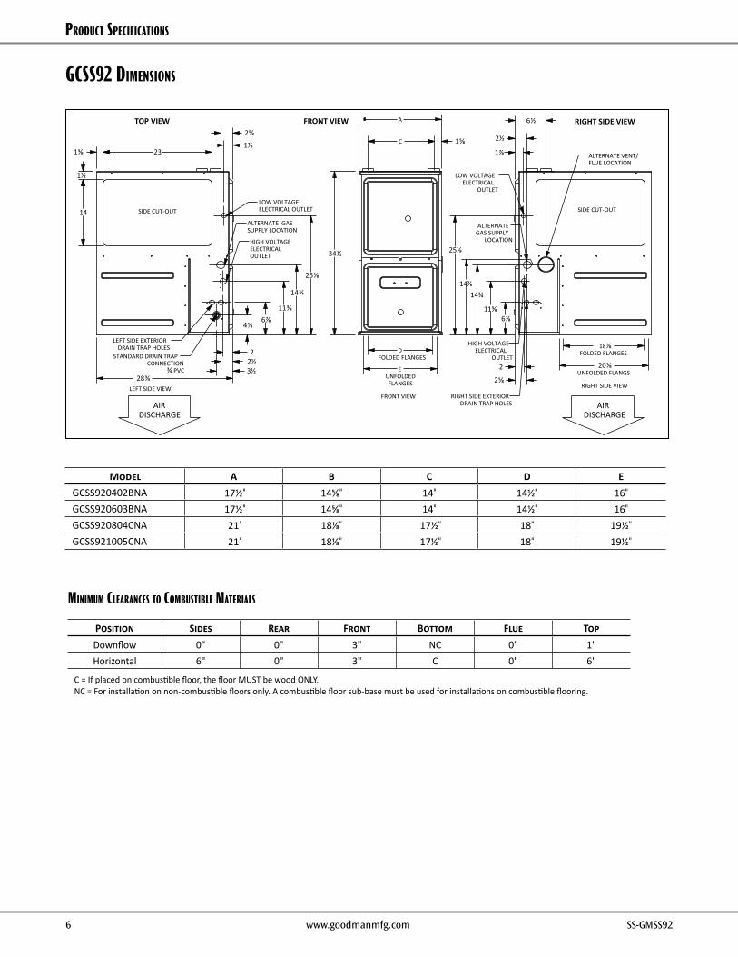
GCSS92 diMenSionS
Model A B C D EGCSS920402BNA 17½" 14⅝" 14" 14½" 16"
GCSS920603BNA 17½" 14⅝" 14" 14½" 16"
GCSS920804CNA 21" 18⅛" 17½" 18" 19½"
GCSS921005CNA 21" 18⅛" 17½" 18" 19½"
MiniMuM ClearanCeS to CoMBuStiBle MaterialS
Position Sides Rear Front Bottom Flue TopDownflow 0" 0" 3" NC 0" 1"Horizontal 6" 0" 3" C 0" 6"
C = If placed on combustible floor, the floor MUST be wood ONLY.NC = For installation on non-combustible floors only. A combustible floor sub-base must be used for installations on combustible flooring.
A
34½
4⅛
11⅜
14¾
25⅛
28¾
C
6⅞ 6⅞11⅜
14⅞14¾
25⅛
3½ 2½
2
1⅞
2⅝
23
14
1⅜
1½
1⅝
EUNFOLDEDFLANGES
DFOLDED FLANGES
18⅛FOLDED FLANGES
20⅛UNFOLDED FLANGS
2⅝
1⅞
2½
6½
2
AIRDISCHARGE
SIDE CUT-OUT SIDE CUT-OUT
AIRDISCHARGE
LEFT SIDE VIEWFRONT VIEW
RIGHT SIDE VIEW
LOW VOLTAGEELECTRICAL OUTLET
ALTERNATE GASSUPPLY LOCATION
HIGH VOLTAGEELECTRICAL OUTLET
STANDARD DRAIN TRAPCONNECTION
¾ PVC
LEFT SIDE EXTERIORDRAIN TRAP HOLES
ALTERNATE GAS SUPPLY
LOCATION
ALTERNATE VENT/FLUE LOCATION
HIGH VOLTAGEELECTRICAL
OUTLET
RIGHT SIDE EXTERIORDRAIN TRAP HOLES
LOW VOLTAGEELECTRICAL
OUTLET
RIGHT SIDE VIEWTOP VIEW FRONT VIEW

Product SPecificationS
6 www.goodmanmfg.com SS-GMSS92 SS-GMSS92 www.goodmanmfg.com 7
airFlow data – GMSS92
(CFM & Temperature Rise vs. External Static Pressure)
Model MotorSpeed
Tons AC¹
External Static Pressure, (Inches Water Column)
0.1 0.2 0.3 0.4 0.5 0.6 0.7 0.8
CFM Rise CFM Rise CFM Rise CFM Rise CFM Rise CFM CFM CFM
GMSS92 0402BNA
High 3 1,498 N/A 1,446 N/A 1,368 N/A 1,302 N/A 1,227 N/A 1,145 1,059 954Med 2.5 1,223 N/A 1,182 N/A 1,153 30 1,099 31 1,051 32 982 901 813
Med-Lo 2 983 35 971 35 945 36 919 37 878 39 813 746 659Low 1.5 816 42 794 43 758 45 734 46 678 50 637 597 523
GMSS92 0603BNA
High 3 1,494 N/A 1,428 36 1,362 38 1,294 39 1,231 42 1,162 1,076 972Med 2.5 1,203 42 1,178 43 1,147 45 1,101 46 1,045 49 986 927 831
Med-Lo 2 977 52 965 53 939 54 904 57 866 59 801 763 639Low 1.5 801 64 786 65 751 N/A 714 N/A 714 N/A 680 635 596
GMSS92 0803BNA
High 3 1,459 47 1,397 49 1,339 51 1,270 54 1,202 57 1,107 1,049 952Med 2.5 1,191 57 1,166 58 1,137 60 1,086 63 1,033 N/A 973 889 797
Med-Lo 2 985 N/A 967 N/A 932 N/A 900 N/A 859 N/A 805 731 620Low 1.5 808 N/A 785 N/A 758 N/A 726 N/A 679 N/A 629 590 513
GMSS92 0804CNA
High 5 2,115 N/A 2,050 N/A 1,973 35 1,915 36 1,810 38 1,695 1,587 1,467Med 4 1,802 38 1,739 39 1,725 40 1,665 41 1,612 42 1,532 1,443 1,320
Med-Lo 3.5 1,517 45 1,509 45 1,496 46 1,475 46 1,441 47 1,388 1,304 1,205Low 3 1,213 56 1,225 56 1,216 56 1,194 57 1,179 58 1,135 1,084 1,005
GMSS92 0805CNA
High 5 2,284 30 2,231 31 2,170 31 2,103 32 2,037 33 1,945 1,836 1,750Med 4 1,865 37 1,869 36 1,775 38 1,732 39 1,684 40 1,619 1,548 1,480
Med-Lo 3.5 1,594 43 1,571 43 1,530 45 1,492 46 1,454 47 1,414 1,355 1,293Low 3 1,411 48 1,366 50 1,325 51 1,296 53 1,251 54 1,200 1,147 1,096
GMSS92 1004CNA
High 5 2,082 41 1,997 43 1,943 44 1,847 46 1,749 49 1,669 1,560 1,443Med 4 1,823 47 1,782 48 1,711 50 1,659 51 1,574 54 1,513 1,402 1,305
Med-Lo 3.5 1,565 54 1,545 55 1,529 56 1,487 57 1,441 59 1,365 1,287 1,196Low 3 1,261 N/A 1237 N/A 1,242 N/A 1,216 N/A 1,179 N/A 1,145 1,098 1,034
GMSS92 1005CNA
High 5 2,137 40 2,073 41 2,031 42 1,949 44 1,879 45 1,811 1,734 1,625
Med 4 1,793 48 1,754 49 1,704 50 1,648 52 1,590 54 1,534 1,451 1,371
Med-Lo 3.5 1,558 55 1,518 56 1,477 58 1,425 60 1,376 62 1,316 1,242 1,170
Low 3 1,370 62 1,325 64 1,288 N/A 1,237 N/A 1,191 N/A 1,134 1,086 1,024
GMSS92 1205DNA
High 5 2,256 45 2,192 47 2,133 48 2,054 50 1,986 51 1,907 1,834 1,718
Med 4 1,805 57 1,762 58 1,722 59 1,677 61 1,618 63 1,563 1,507 1,441
Med-Lo 3.5 1,565 65 1,513 N/A 1,480 N/A 1,415 N/A 1,392 N/A 1,346 1,269 1,198
Low 3 1,368 N/A 1,326 N/A 1,278 N/A 1,238 N/A 1,208 N/A 1,165 1,093 1,052
¹ at 0.5" ESP
Notes• CFM in chart is without filter(s). Filters do not ship with this furnace, but must be provided by the installer. If the furnace requires two return filters,
this chart assumes both filters are installed.• All furnaces ship as high-speed cooling and medium-speed heating. Installer must adjust blower cooling & heating speed as needed.• For most jobs, about 400 CFM per ton when cooling is desirable.• INSTALLATION IS TO BE ADJUSTED TO OBTAIN TEMPERATURE RISE WITHIN THE RANGE SPECIFIED ON THE RATING PLATE.• This chart is for information only. For satisfactory operation, external static pressure should not exceed value shown on the rating plate.
The shaded area indicates ranges in excess of maximum static pressure allowed when heating.• The above chart is for U.S. furnaces installed at 0-2000 feet. At higher altitudes, a properly derated unit will have approximately the same
temperature rise at a particular CFM, while ESP at the CFM will be lower.
Product SPecificationS
8 www.goodmanmfg.com SS-GMSS92 SS-GMSS92 www.goodmanmfg.com 9
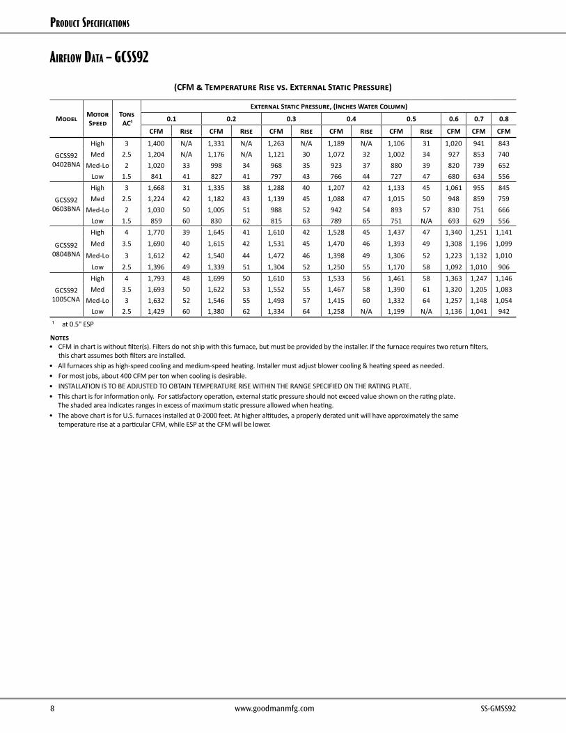
airFlow data – GCSS92
(CFM & Temperature Rise vs. External Static Pressure)
Model MotorSpeed
Tons AC¹
External Static Pressure, (Inches Water Column)
0.1 0.2 0.3 0.4 0.5 0.6 0.7 0.8
CFM Rise CFM Rise CFM Rise CFM Rise CFM Rise CFM CFM CFM
GCSS92 0402BNA
High 3 1,400 N/A 1,331 N/A 1,263 N/A 1,189 N/A 1,106 31 1,020 941 843Med 2.5 1,204 N/A 1,176 N/A 1,121 30 1,072 32 1,002 34 927 853 740
Med-Lo 2 1,020 33 998 34 968 35 923 37 880 39 820 739 652Low 1.5 841 41 827 41 797 43 766 44 727 47 680 634 556
GCSS92 0603BNA
High 3 1,668 31 1,335 38 1,288 40 1,207 42 1,133 45 1,061 955 845Med 2.5 1,224 42 1,182 43 1,139 45 1,088 47 1,015 50 948 859 759
Med-Lo 2 1,030 50 1,005 51 988 52 942 54 893 57 830 751 666Low 1.5 859 60 830 62 815 63 789 65 751 N/A 693 629 556
GCSS92 0804BNA
High 4 1,770 39 1,645 41 1,610 42 1,528 45 1,437 47 1,340 1,251 1,141Med 3.5 1,690 40 1,615 42 1,531 45 1,470 46 1,393 49 1,308 1,196 1,099
Med-Lo 3 1,612 42 1,540 44 1,472 46 1,398 49 1,306 52 1,223 1,132 1,010Low 2.5 1,396 49 1,339 51 1,304 52 1,250 55 1,170 58 1,092 1,010 906
GCSS92 1005CNA
High 4 1,793 48 1,699 50 1,610 53 1,533 56 1,461 58 1,363 1,247 1,146Med 3.5 1,693 50 1,622 53 1,552 55 1,467 58 1,390 61 1,320 1,205 1,083
Med-Lo 3 1,632 52 1,546 55 1,493 57 1,415 60 1,332 64 1,257 1,148 1,054Low 2.5 1,429 60 1,380 62 1,334 64 1,258 N/A 1,199 N/A 1,136 1,041 942
¹ at 0.5" ESP
Notes• CFM in chart is without filter(s). Filters do not ship with this furnace, but must be provided by the installer. If the furnace requires two return filters,
this chart assumes both filters are installed.• All furnaces ship as high-speed cooling and medium-speed heating. Installer must adjust blower cooling & heating speed as needed.• For most jobs, about 400 CFM per ton when cooling is desirable.• INSTALLATION IS TO BE ADJUSTED TO OBTAIN TEMPERATURE RISE WITHIN THE RANGE SPECIFIED ON THE RATING PLATE.• This chart is for information only. For satisfactory operation, external static pressure should not exceed value shown on the rating plate.
The shaded area indicates ranges in excess of maximum static pressure allowed when heating.• The above chart is for U.S. furnaces installed at 0-2000 feet. At higher altitudes, a properly derated unit will have approximately the same
temperature rise at a particular CFM, while ESP at the CFM will be lower.
Product SPecificationS
8 www.goodmanmfg.com SS-GMSS92 SS-GMSS92 www.goodmanmfg.com 9
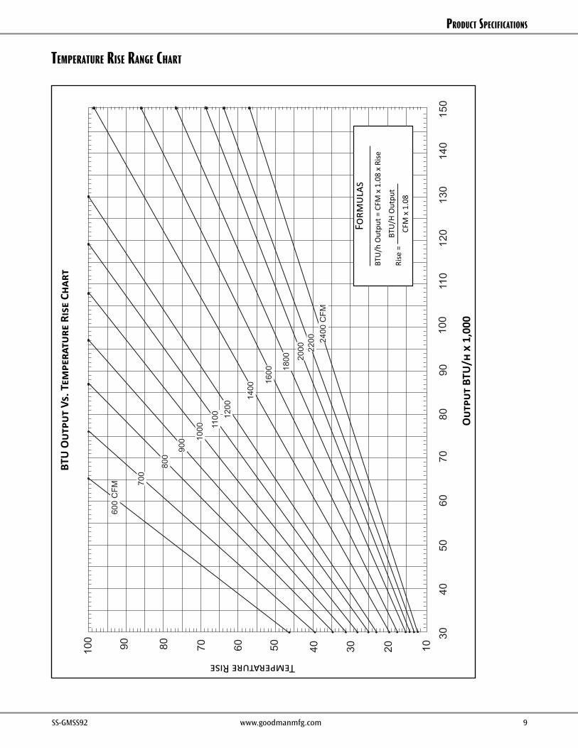
teMperature riSe ranGe CHart
3040
5060
7080
9011
012
010
013
014
015
0
100
90 80 70 60 50 40 30 20 10
OU
TPU
TB
TU/H
Rx
1000
BTU
OU
TPU
Tvs
TEM
PE
RAT
UR
ER
ISE
CH
AR
T
TEMPERATURERISE
600
CFM
700
900 10
00 1100 12
00
1400
1600 18
00 2000 22
00 2400
CFM
FOR
MU
LAS
BTU
OU
TPU
T=
CFM
x1.
08x
RIS
E
RIS
E=
BTU
OU
TPU
T1.
08÷
CFM
800
Temperature Rise
Out
put
BTU
/h x
1,0
00
Form
ulas
BTU
/h O
utpu
t = C
FM x
1.0
8 x
Rise
Rise
=
BTU
/H O
utpu
t
CFM
x 1
.08
BTU
Out
put
Vs. T
empe
ratu
re R
ise
Char
t
Product SPecificationS
10 www.goodmanmfg.com SS-GMSS92 SS-GMSS92 www.goodmanmfg.com 11
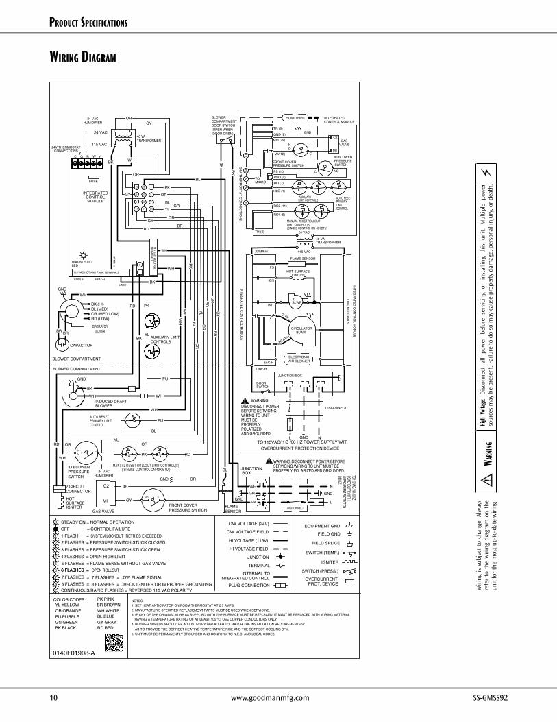
wirinG diaGraM
Wiri
ng i
s su
bjec
t to
cha
nge.
Alw
ays
refe
r to
the
wiri
ng d
iagr
am o
n th
e un
it fo
r th
e m
ost u
p-to
-dat
e w
iring
.⚠
Wa
rnin
gHi
gh V
olta
ge:
Dis
conn
ect
all
pow
er b
efor
e se
rvic
ing
or i
nsta
lling
thi
s un
it. M
ultip
le p
ower
so
urce
s m
ay b
e pr
esen
t. Fa
ilure
to d
o so
may
cau
se p
rope
rty
dam
age,
per
sona
l inj
ury,
or
deat
h.⚡
R
YL YELLOWOR ORANGEPU PURPLEGN GREENBK BLACK
BR BROWNWH WHITEBL BLUEGY GRAYRD RED
COLOR CODES:
LOW VOLTAGE (24V)
LOW VOLTAGE FIELD
HI VOLTAGE (115V)
HI VOLTAGE FIELD
NOTES:1. SET HEAT ANTICIPATOR ON ROOM THERMOSTAT AT 0.7 AMPS.2. MANUFACTUR'S SPECIFIED REPLACEMENT PARTS MUST BE USED WHEN SERVICING.
0140F01908-A
OR (MED LOW)BL (MED)
RD (LOW)
GAS VALVE
C2
C G W
INTERNAL TOINTEGRATED CONTROL
JUNCTION
EQUIPMENT GND
FIELD GND
DIAGNOSTICLED
2 CIRCUITCONNECTOR
HOTSURFACEIGNITER
OVERCURRENTPROT. DEVICE
IGNITER
TH (3)
INTEGRATEDCONTROL MODULE
JUNCTION BOX
LINE-H
XFMR-H
INTEGRATED C
ON
TROL M
ODULE
INTEGRATED
CON
TROL M
ODULE
GND
DISCONNECT
L N
DISCONNECT POWERBEFORE SERVICING.WIRING TO UNITMUST BEPROPERLYPOLARIZEDAND GROUNDED.
OVERCURRENT PROTECTION DEVICE
RD
BL
BK
4. BLOWER SPEEDS SHOULD BE ADJUSTED BY INSTALLER TO MATCH THE INSTALLATION REQUIREMENTS SOAS TO PROVIDE THE CORRECT HEATING TEMPERATURE RISE AND THE CORRECT COOLING CFM.
3. IF ANY OF THE ORIGINAL WIRE AS SUPPLIED WITH THE FURNACE MUST BE REPLACED, IT MUST BE REPLACED WITH WIRING MATERIALHAVING A TEMPERATURE RATING OF AT LEAST 105
TERMINALSWITCH (PRESS.)
5. UNIT MUST BE PERMANENTLY GROUNDED AND CONFORM TO N.E.C. AND LOCAL CODES.
PK PINK
115 VAC HOT AND PARK TERMINALS
LINE-H
FLAMESENSOR
( SINGLE CONTROL ON 40K BTU )
BK
PLUG CONNECTION
FIELD SPLICE
SWITCH (TEMP.)
OR
24V THERMOSTATCONNECTIONS
GRGND
115 VAC
24 VAC
BLOWERCOMPARTMENTDOOR SWITCH(OPEN WHENDOOR OPEN)
DOORSWITCH
WARNING:DISCONNECT POWER BEFORESERVICING.WIRING TO UNIT MUST BEPROPERLY POLARIZED AND GROUNDED.
BK
GND
DISCONNECTL
N
POWER SUPPLY WITHOVERCURRENT PROTECTIONDEVICE
WH
JUNCTIONBOX
1
TO 115 VAC / 1Ø / 60HZ
OR
ID BLOWERPRESSURESWITCH
HEAT-H
GNDWH
RD
WH
GND
BURNER COMPARTMENT
BLOWER COMPARTMENT
NO
COOL-H
BK (HI)
BR BR
CAPACITOR
YL
WH
CO NTR O LPRIMA RY LIMITAUTO RE SET
BL
PU
MA NUAL R ESET RO LLO UT L IMIT CO NTR O L(S)
RD
OR
PK
BK
WH WH
BLOWERINDUCED DRAFT
AUXILIARY LIMITCONTROLS
C
CIRCULATORBLOWER
FS
LIMIT CONTROLSAUXILIARY
HEAT-H
COOL
IGNITERHOT SURFACE
IND
IGN
BLWRCIRCULATOR
BLWRID
FLAME SENSOR
115 VAC
TRANSFORMER40 VA
24 VAC
GND
CONTROLLIMITPRIMARYAUTO RESET
(SINGLE CONTROL ON 40K BTU)LIMIT CONTROL(S)MANUAL RESET ROLLOUT
RO1 (5)
RO2 (11)
HLO (1)
HLI (7)
MVC (9)GND (8)
TR (6)
OR
WH
WH
BL
YLO
RRD
GR
BR
PK
PK
WH
115 VAC NEU
TRAL
BK
BK
BK
GY
24V THERMO
STAT CONNECTIO
NS
MICROTO
C
G
Y
W
R
TRANSFORMER40 VA
2
WH
OR
BLYL
OR
PK
RD
OR
WH
XFMR-H
TERM
INALS
BL
GY
GR
123
12 11 10
9 8 7
6 5 4
WARNING:
°C. USE COPPER CONDUCTORS ONLY.
24 VACHUMIDIFIER
24 VACHUMIDIFIER
HUMIDIFIER
PSO (4)
MV(12)
PS (10) C NO
ID BLOWERPRESSURESWITCH
OFF = CONTROL FAILURESTEADY ON = NORMAL OPERATION
1 FLASH =2 FLASHES = PRESSURE SWITCH STUCK CLOSED3 FLASHES = PRESSURE SWITCH STUCK OPEN4 FLASHES = OPEN HIGH LIMIT5 FLASHES = FLAME SENSE WITHOUT GAS VALVE
OPEN ROLLOUT6 FLASHES =
SYSTEM LOCKOUT (RETRIES EXCEEDED)
CONTINUOUS/RAPID FLASHES = REVERSED 115 VAC POLARITY
CONTROLMODULE
INTEGRATED
FUSE
MI GY
GY
M1
GASVALVE
C2
TO 115VAC/ 1Ø /60 HZ POWER SUPPLY WITH
PU
Y
BR
GY
BR
LINE NEUTRALS
NO C
FRONT COVERPRESSURE SWITCH
C
NO
FRONT COVERPRESSURE SWITCH
YL
7 FLASHES =8 FLASHES =
6 FLASHES =7 FLASHES = LOW FLAME SIGNAL8 FLASHES = CHECK IGNITER OR IMPROPER GROUNDING
ELECTRONICAIR CLEANEREAC-H
GNDGR

Product SPecificationS
10 www.goodmanmfg.com SS-GMSS92 SS-GMSS92 www.goodmanmfg.com 11
aCCeSSorieS – GMSS92 / GCSS92
Model Description GMSS92 0402BNA
GMSS92 0603BNA
GMSS92 0803BNA
GMSS92 0804CNA
GMSS92 0805CNA
GMSS92 1004CNA
GMSS92 1005CNA
GMSS92 1205DNA
CVENT-2 Concentric Vent Kit (2") √ √ √ √ √ √ √ ---CVENT-3 Concentric Vent Kit (3") √ √ √ √ √ √ √ √CFSB17 Downflow Sub-Base 17.5" --- --- --- --- --- --- --- ---CFSB21 Downflow Sub-Base 21" --- --- --- --- --- --- --- ---CFSB24 Downflow Sub-Base 24" --- --- --- --- --- --- --- ---RF000142 Drain Kit -Horizontal Left Vertical Flue √ √ √ √ √ √ √ √
EFR01 External Filter Rack with 16"x25" Permanent Filter TBD TBD TBD TBD TBD TBD TBD TBD
0170K00000S Flush Mount Vent Kit - 3" or 2" √ √ √ √ √ √ √ √0170K00001S Flush Mount Vent Kit - 2" √ √ √ √ √ √ √ ---AFE18-60A Fossil Fuel (Duel Fuel) Kit √ √ √ √ √ √ √ √
High-Altitude Natural Gas Kit TBD TBD TBD TBD TBD TBD TBD TBDHigh-Altitude Pressure Switch TBD TBD TBD TBD TBD TBD TBD TBDHigh-Altitude LP Gas Kit TBD TBD TBD TBD TBD TBD TBD TBD
LPLP03 Low LP Gas Pressure Switch √ √ √ √ √ √ √ √LPM-07 LP Conversion Kits (Gas Valve) √ √ √ √ √ √ √ √FTK04 Twinning Kit √ √ √ √ √ √ √ √
Model Description GCSS92 0402BNA
GCSS92 0603BNA
GCSS92 0804CNA
GCSS92 1005CNA
CVENT-2 Concentric Vent Kit (2") √ √ √ √CVENT-3 Concentric Vent Kit (3") √ √ √ √CFSB17 Downflow Sub-Base 17.5" √ √ --- ---CFSB21 Downflow Sub-Base 21" --- --- √ √CFSB24 Downflow Sub-Base 24" --- --- --- ---RF000142 Drain Kit -Horizontal Left Vertical Flue --- --- --- ---EFR01 External Filter Rack with 16"x25" Permanent Filter TBD TBD TBD TBD0170K00000S Flush Mount Vent Kit - 3" or 2" √ √ √ √0170K00001S Flush Mount Vent Kit - 2" √ √ √ √AFE18-60A Fossil Fuel (Duel Fuel) Kit √ √ √ √
High-Altitude Natural Gas Kit TBD TBD TBD TBDHigh-Altitude Pressure Switch TBD TBD TBD TBDHigh-Altitude LP Gas Kit TBD TBD TBD TBD
LPLP03 Low LP Gas Pressure Switch √ √ √ √LPM-07 LP Conversion Kits (Gas Valve) √ √ √ √FTK04 Twinning Kit √ √ √ √
Product SPecificationS
12 www.goodmanmfg.com SS-GMSS92 SS-GMSS92 www.goodmanmfg.com PB
Goodman Manufacturing Company, L.P., reserves the right to discontinue, or change at any time, specifications or designs without notice or without incurring obligations. © 2014 • Goodman Manufacturing Company, L.P. • Houston, Texas • Printed in the USA.
noteS