
gmsh
218
Gmsh
-
Upload
seventhhemanth -
Category
Documents
-
view
74 -
download
11
description
GMSH
Transcript of gmsh

Gmsh


Gmsh Reference ManualThe documentation for Gmsh 1.63
A finite element mesh generator with built-in pre- and post-processing facilities
Edition 1.34 (30 January 2006)
Christophe GeuzaineJean-Francois Remacle

Copyright c© 1997-2006 Christophe Geuzaine, Jean-Francois Remacle
Permission is granted to make and distribute verbatim copies of this manual provided thecopyright notice and this permission notice are preserved on all copies.

i
Short Contents
Copying conditions . . . . . . . . . . . . . . . . . . . . . . . . . . . . . . . . . 1
1 Overview . . . . . . . . . . . . . . . . . . . . . . . . . . . . . . . . . . . . . 3
2 General tools . . . . . . . . . . . . . . . . . . . . . . . . . . . . . . . . . . 9
3 Geometry module . . . . . . . . . . . . . . . . . . . . . . . . . . . . . . 39
4 Mesh module . . . . . . . . . . . . . . . . . . . . . . . . . . . . . . . . . 49
5 Solver module . . . . . . . . . . . . . . . . . . . . . . . . . . . . . . . . . 65
6 Post-processing module . . . . . . . . . . . . . . . . . . . . . . . . . . 83
7 Tutorial . . . . . . . . . . . . . . . . . . . . . . . . . . . . . . . . . . . . 113
8 Running Gmsh . . . . . . . . . . . . . . . . . . . . . . . . . . . . . . . 137
9 File formats . . . . . . . . . . . . . . . . . . . . . . . . . . . . . . . . . 145
10 Programming notes . . . . . . . . . . . . . . . . . . . . . . . . . . . . 159
11 Bugs, versions and credits . . . . . . . . . . . . . . . . . . . . . . . . 161
A Tips and tricks . . . . . . . . . . . . . . . . . . . . . . . . . . . . . . . 175
B Frequently asked questions . . . . . . . . . . . . . . . . . . . . . . . 177
C License. . . . . . . . . . . . . . . . . . . . . . . . . . . . . . . . . . . . . 189
Concept index . . . . . . . . . . . . . . . . . . . . . . . . . . . . . . . . . . . 195
Syntax index . . . . . . . . . . . . . . . . . . . . . . . . . . . . . . . . . . . . 199

ii Gmsh 1.63

iii
Table of Contents
Copying conditions . . . . . . . . . . . . . . . . . . . . . . . . . . . . 1
1 Overview . . . . . . . . . . . . . . . . . . . . . . . . . . . . . . . . . . 31.1 Geometry: geometrical entity definition . . . . . . . . . . . . . . . . . . . . . 31.2 Mesh: finite element mesh generation . . . . . . . . . . . . . . . . . . . . . . . 31.3 Solver: external solver interface . . . . . . . . . . . . . . . . . . . . . . . . . . . . . 41.4 Post-processing: scalar, vector and tensor field visualization . . 41.5 What Gmsh is pretty good at . . . . . . . . . . . . . . . . . . . . . . . . . . . . . 41.6 . . . and what Gmsh is not so good at . . . . . . . . . . . . . . . . . . . . . . . 61.7 Syntactic rules used in this document . . . . . . . . . . . . . . . . . . . . . . . 61.8 Comments . . . . . . . . . . . . . . . . . . . . . . . . . . . . . . . . . . . . . . . . . . . . . . . . 6
2 General tools . . . . . . . . . . . . . . . . . . . . . . . . . . . . . . 92.1 Expressions . . . . . . . . . . . . . . . . . . . . . . . . . . . . . . . . . . . . . . . . . . . . . . . 9
2.1.1 Floating point expressions . . . . . . . . . . . . . . . . . . . . . . . . . . . 92.1.2 Character expressions . . . . . . . . . . . . . . . . . . . . . . . . . . . . . . 102.1.3 Color expressions . . . . . . . . . . . . . . . . . . . . . . . . . . . . . . . . . . 11
2.2 Operators . . . . . . . . . . . . . . . . . . . . . . . . . . . . . . . . . . . . . . . . . . . . . . . 112.3 Built-in functions . . . . . . . . . . . . . . . . . . . . . . . . . . . . . . . . . . . . . . . . 132.4 User-defined functions . . . . . . . . . . . . . . . . . . . . . . . . . . . . . . . . . . . . 142.5 Loops and conditionals . . . . . . . . . . . . . . . . . . . . . . . . . . . . . . . . . . . 142.6 General commands . . . . . . . . . . . . . . . . . . . . . . . . . . . . . . . . . . . . . . . 152.7 General options . . . . . . . . . . . . . . . . . . . . . . . . . . . . . . . . . . . . . . . . . . 18
3 Geometry module . . . . . . . . . . . . . . . . . . . . . . . . 393.1 Geometry commands . . . . . . . . . . . . . . . . . . . . . . . . . . . . . . . . . . . . . 39
3.1.1 Points . . . . . . . . . . . . . . . . . . . . . . . . . . . . . . . . . . . . . . . . . . . . 393.1.2 Lines . . . . . . . . . . . . . . . . . . . . . . . . . . . . . . . . . . . . . . . . . . . . . 403.1.3 Surfaces . . . . . . . . . . . . . . . . . . . . . . . . . . . . . . . . . . . . . . . . . . . 413.1.4 Volumes . . . . . . . . . . . . . . . . . . . . . . . . . . . . . . . . . . . . . . . . . . 423.1.5 Extrusions . . . . . . . . . . . . . . . . . . . . . . . . . . . . . . . . . . . . . . . . 423.1.6 Transformations . . . . . . . . . . . . . . . . . . . . . . . . . . . . . . . . . . . 433.1.7 Miscellaneous . . . . . . . . . . . . . . . . . . . . . . . . . . . . . . . . . . . . . . 43
3.2 Geometry options . . . . . . . . . . . . . . . . . . . . . . . . . . . . . . . . . . . . . . . . 44
4 Mesh module . . . . . . . . . . . . . . . . . . . . . . . . . . . . . 494.1 Elementary vs. physical entities . . . . . . . . . . . . . . . . . . . . . . . . . . . 494.2 Mesh commands . . . . . . . . . . . . . . . . . . . . . . . . . . . . . . . . . . . . . . . . . 49
4.2.1 Characteristic lengths . . . . . . . . . . . . . . . . . . . . . . . . . . . . . . 494.2.2 Structured grids . . . . . . . . . . . . . . . . . . . . . . . . . . . . . . . . . . . 514.2.3 Miscellaneous . . . . . . . . . . . . . . . . . . . . . . . . . . . . . . . . . . . . . . 52
4.3 Mesh options . . . . . . . . . . . . . . . . . . . . . . . . . . . . . . . . . . . . . . . . . . . . 53

iv Gmsh 1.63
5 Solver module . . . . . . . . . . . . . . . . . . . . . . . . . . . . 655.1 Solver options . . . . . . . . . . . . . . . . . . . . . . . . . . . . . . . . . . . . . . . . . . . . 655.2 Solver example . . . . . . . . . . . . . . . . . . . . . . . . . . . . . . . . . . . . . . . . . . . 79
6 Post-processing module . . . . . . . . . . . . . . . . . . . 836.1 Post-processing commands . . . . . . . . . . . . . . . . . . . . . . . . . . . . . . . . 836.2 Post-processing plugins . . . . . . . . . . . . . . . . . . . . . . . . . . . . . . . . . . . 856.3 Post-processing options . . . . . . . . . . . . . . . . . . . . . . . . . . . . . . . . . . . 96
7 Tutorial . . . . . . . . . . . . . . . . . . . . . . . . . . . . . . . . . 1137.1 ‘t1.geo’ . . . . . . . . . . . . . . . . . . . . . . . . . . . . . . . . . . . . . . . . . . . . . . . . 1137.2 ‘t2.geo’ . . . . . . . . . . . . . . . . . . . . . . . . . . . . . . . . . . . . . . . . . . . . . . . . 1157.3 ‘t3.geo’ . . . . . . . . . . . . . . . . . . . . . . . . . . . . . . . . . . . . . . . . . . . . . . . . 1177.4 ‘t4.geo’ . . . . . . . . . . . . . . . . . . . . . . . . . . . . . . . . . . . . . . . . . . . . . . . . 1197.5 ‘t5.geo’ . . . . . . . . . . . . . . . . . . . . . . . . . . . . . . . . . . . . . . . . . . . . . . . . 1227.6 ‘t6.geo’ . . . . . . . . . . . . . . . . . . . . . . . . . . . . . . . . . . . . . . . . . . . . . . . . 1257.7 ‘t7.geo’ . . . . . . . . . . . . . . . . . . . . . . . . . . . . . . . . . . . . . . . . . . . . . . . . 1317.8 ‘t8.geo’ . . . . . . . . . . . . . . . . . . . . . . . . . . . . . . . . . . . . . . . . . . . . . . . . 1327.9 ‘t9.geo’ . . . . . . . . . . . . . . . . . . . . . . . . . . . . . . . . . . . . . . . . . . . . . . . . 135
8 Running Gmsh . . . . . . . . . . . . . . . . . . . . . . . . . . 1378.1 Interactive mode . . . . . . . . . . . . . . . . . . . . . . . . . . . . . . . . . . . . . . . . 1378.2 Non-interactive mode . . . . . . . . . . . . . . . . . . . . . . . . . . . . . . . . . . . . 1388.3 Command-line options . . . . . . . . . . . . . . . . . . . . . . . . . . . . . . . . . . . 1388.4 Mouse actions . . . . . . . . . . . . . . . . . . . . . . . . . . . . . . . . . . . . . . . . . . . 1408.5 Keyboard shortcuts . . . . . . . . . . . . . . . . . . . . . . . . . . . . . . . . . . . . . 140
9 File formats . . . . . . . . . . . . . . . . . . . . . . . . . . . . . 1459.1 Gmsh mesh file formats . . . . . . . . . . . . . . . . . . . . . . . . . . . . . . . . . . 145
9.1.1 Version 1.0 . . . . . . . . . . . . . . . . . . . . . . . . . . . . . . . . . . . . . . . 1459.1.2 Version 2.0 . . . . . . . . . . . . . . . . . . . . . . . . . . . . . . . . . . . . . . . 146
9.2 Gmsh post-processing file formats . . . . . . . . . . . . . . . . . . . . . . . . 1489.2.1 Parsed post-processing file format . . . . . . . . . . . . . . . . . . 1499.2.2 ASCII post-processing file format . . . . . . . . . . . . . . . . . . 1519.2.3 Binary post-processing file format . . . . . . . . . . . . . . . . . . 154
9.3 Gmsh node ordering . . . . . . . . . . . . . . . . . . . . . . . . . . . . . . . . . . . . . 155
10 Programming notes . . . . . . . . . . . . . . . . . . . . . 15910.1 Coding style . . . . . . . . . . . . . . . . . . . . . . . . . . . . . . . . . . . . . . . . . . . 15910.2 Option handling . . . . . . . . . . . . . . . . . . . . . . . . . . . . . . . . . . . . . . . 159
11 Bugs, versions and credits . . . . . . . . . . . . . . . 16111.1 Bugs . . . . . . . . . . . . . . . . . . . . . . . . . . . . . . . . . . . . . . . . . . . . . . . . . . 16111.2 Versions . . . . . . . . . . . . . . . . . . . . . . . . . . . . . . . . . . . . . . . . . . . . . . . 16111.3 Credits . . . . . . . . . . . . . . . . . . . . . . . . . . . . . . . . . . . . . . . . . . . . . . . . 171

v
Appendix A Tips and tricks . . . . . . . . . . . . . . . . 175
Appendix B Frequently asked questions . . . . . 177
Appendix C License . . . . . . . . . . . . . . . . . . . . . . . . 189
Concept index . . . . . . . . . . . . . . . . . . . . . . . . . . . . . . 195
Syntax index . . . . . . . . . . . . . . . . . . . . . . . . . . . . . . . 199

vi Gmsh 1.63

Copying conditions 1
Copying conditions
Gmsh is “free software”; this means that everyone is free to use it and to redistribute it ona free basis. Gmsh is not in the public domain; it is copyrighted and there are restrictionson its distribution, but these restrictions are designed to permit everything that a goodcooperating citizen would want to do. What is not allowed is to try to prevent others fromfurther sharing any version of Gmsh that they might get from you.Specifically, we want to make sure that you have the right to give away copies of Gmsh,that you receive source code or else can get it if you want it, that you can change Gmsh oruse pieces of Gmsh in new free programs, and that you know you can do these things.To make sure that everyone has such rights, we have to forbid you to deprive anyone else ofthese rights. For example, if you distribute copies of Gmsh, you must give the recipients allthe rights that you have. You must make sure that they, too, receive or can get the sourcecode. And you must tell them their rights.Also, for our own protection, we must make certain that everyone finds out that there isno warranty for Gmsh. If Gmsh is modified by someone else and passed on, we want theirrecipients to know that what they have is not what we distributed, so that any problemsintroduced by others will not reflect on our reputation.The precise conditions of the license for Gmsh are found in the General PublicLicense that accompanies the source code (see Appendix C [License], page 189).Further information about this license is available from the GNU Project webpagehttp://www.gnu.org/copyleft/gpl-faq.html. Detailed copyright information can befound in Section 11.3 [Credits], page 171.The source code and various pre-compiled versions of Gmsh (for Unix, Windows and MacOS) can be downloaded from the webpage http://geuz.org/gmsh/.If you use Gmsh, we would appreciate that you mention it in your work. Refer-ences, as well as the latest news about Gmsh development, are always available onhttp://geuz.org/gmsh/. Please send all Gmsh-related questions to the public Gmshmailing list at [email protected].
If you want to integrate Gmsh into a closed-source software, or want to sell a modifiedclosed-source version of Gmsh, please contact one of the authors. You can purchase aversion of Gmsh under a different license, with “no strings attached” (for example allowingyou to take parts of Gmsh and integrate them into your own proprietary code).

2 Gmsh 1.63

Chapter 1: Overview 3
1 Overview
Gmsh is an automatic three-dimensional finite element mesh generator, primarily Delau-nay, with built-in pre- and post-processing facilities. Its design goal is to provide a simplemeshing tool for academic problems with parametric input and advanced visualization ca-pabilities.Gmsh is built around four modules: geometry, mesh, solver and post-processing. All ge-ometrical, mesh, solver and post-processing instructions are prescribed either interactivelyusing the graphical user interface (GUI) or in ASCII data files using Gmsh’s own scriptinglanguage. Interactive actions generate language bits in the input files, and vice versa. Thismakes it possible to automate all treatments, using loops, conditionals and external systemcalls. A brief description of the four modules is given hereafter.
1.1 Geometry: geometrical entity definition
Geometries are created in a bottom-up flow by successively defining points, oriented lines(line segments, circles, ellipses, splines, . . . ), oriented surfaces (plane surfaces, ruled sur-faces, triangulated surfaces, . . . ) and volumes. Compound groups of geometrical entitiescan be defined, based on these elementary geometric entities. Gmsh’s scripting languageallows all geometrical entities to be fully parameterized.
1.2 Mesh: finite element mesh generation
A finite element mesh is a tessellation of a given subset of the three-dimensional spaceby elementary geometrical elements of various shapes (in Gmsh’s case: lines, triangles,quadrangles, tetrahedra, prisms, hexahedra and pyramids), arranged in such a way that iftwo of them intersect, they do so along a face, an edge or a node, and never otherwise.All the finite element meshes produced by Gmsh are considered as “unstructured”, evenif they were generated in a “structured” way (e.g., by extrusion). This implies that theelementary geometrical elements are defined only by an ordered list of their nodes but thatno predefined order relation is assumed between any two elements.The mesh generation is performed in the same bottom-up flow as the geometry creation:lines are discretized first; the mesh of the lines is then used to mesh the surfaces; thenthe mesh of the surfaces is used to mesh the volumes. In this process, the mesh of anentity is only constrained by the mesh of its boundary1. This automatically assures theconformity of the mesh when, for example, two surfaces share a common line. But this
1 For example, in three dimensions:
• the triangles discretizing a surface will be forced to be faces of tetrahedra in the final 3D mesh only ifthe surface is part of the boundary of a volume;
• the line elements discretizing a curve will be forced to be edges of tetrahedra in the final 3D mesh onlyif the curve is part of the boundary of a surface, itself part of the boundary of a volume;
• a single node discretizing a point in the middle of a volume will be forced to be a vertex of one of thetetrahedra in the final 3D mesh only if this point is connected to a curve, itself part of the boundaryof a surface, itself part of the boundary of a volume...
4 Gmsh 1.63
also implies that the discretization of an “isolated” (n-1)-th dimensional entity inside ann-th dimensional entity does not constrain the n-th dimensional mesh. Every meshingstep is constrained by the characteristic length field, which can be uniform, specified bycharacteristic lengths associated with elementary geometrical entities, or associated withanother mesh (the background mesh).
For each meshing step, all structured mesh directives are executed first, and serve as ad-ditional constraints for the unstructured parts. The implemented Delaunay algorithm issubdivided in the following five steps for surface/volume discretization:
1. trivial meshing of a box including the convex polygon/polyhedron defined by the bound-ary nodes resulting from the discretization of the lines/surfaces;
2. creation of the initial mesh by insertion of all the nodes on the lines/surfaces thanksto the Bowyer algorithm;
3. boundary restoration to force all the edges/faces of the lines/surfaces to be present inthe initial mesh;
4. suppression of all the unwanted triangles/tetrahedra (in particular those containing thenodes of the initial box);
5. insertion of new nodes by the Bowyer algorithm until the characteristic size of eachsimplex is lower or equal to the characteristic length field evaluated at the center of itscircumscribed circle/sphere.
1.3 Solver: external solver interface
External solvers can be interfaced with Gmsh through Unix or TCP/IP sockets, whichpermits to easily launch external computations and to collect and exploit the simulationresults within Gmsh’s post-processing module. The default solver interfaced with Gmsh isGetDP (http://www.geuz.org/getdp/). Small examples of solvers written in C, C++, Perland Python are available in the source distribution (in the ‘utils/solvers/’ directory).
1.4 Post-processing: scalar, vector and tensor fieldvisualization
Multiple post-processing scalar, vector or tensor maps can be loaded and manipulated(globally or individually) along with the geometry and the mesh. Scalar fields are rep-resented by iso-value lines/surfaces or color maps, while vector fields are represented bythree-dimensional arrows or displacement maps. Post-processing functions include sectioncomputation, offset, elevation, boundary and component extraction, color map and rangemodification, animation, vector graphic output, etc. All post-processing options can beaccessed either interactively or through the input ASCII text files. Scripting permits toautomate all post-processing operations, e.g., for the creation of animations. User-definedoperations can also be performed on post-processing views through dynamically loadableplugins.

Chapter 1: Overview 5
1.5 What Gmsh is pretty good at . . .
Gmsh is a (relatively) small program, and was principally developed “in academia, to solveacademic problems”. . . Nevertheless, over the years, many people outside universities havefound Gmsh useful in their day-to-day jobs. Here is a tentative list of what Gmsh doesbest:• quickly describe simple and/or “repetitive” geometries, thanks to user-defined func-
tions, loops, conditionals and includes (see Section 2.4 [User-defined functions], page 14,Section 2.5 [Loops and conditionals], page 14, and Section 2.6 [General commands],page 15);
• parameterize these geometries. Gmsh’s scripting language enables all commands andcommand arguments to depend on previous calculations (see Section 2.1 [Expressions],page 9, and Section 3.1 [Geometry commands], page 39);
• generate 1D, 2D and 3D simplicial (i.e., using line segments, triangles and tetrahedra)finite element meshes. The performance of the 1D and 2D algorithms is pretty good;the 3D algorithm is still experimental and slow (see Chapter 4 [Mesh module], page 49,and Chapter 7 [Tutorial], page 113);
• specify target element sizes accurately. Gmsh provides several mechanisms to controlthe size of the elements in the final mesh: through interpolation from geometricalpoint characteristic lengths or geometrical attractors, or from user-defined backgroundmeshes (see Section 4.2 [Mesh commands], page 49);
• create simple extruded geometries and meshes (see Section 3.1 [Geometry commands],page 39, and Section 4.2 [Mesh commands], page 49);
• interact with external solvers. Gmsh provides C, C++, Perl and Python interfaces, andothers can be easily added (see Chapter 5 [Solver module], page 65);
• visualize computational results in a great variety of ways. Gmsh can display scalar,vector and tensor data sets, and can perform various operations on the resulting post-processing views (see Chapter 6 [Post-processing module], page 83);
• export plots in many different formats: vector PostScript or encapsulated PostScript,LaTeX, PNG, JPEG, . . . (see Section 2.7 [General options], page 18);
• generate complex animations (see Chapter 2 [General tools], page 9, and Section 7.8[t8.geo], page 132);
• run on low end machines and/or machines with no graphic system. Gmsh can becompiled with or without the graphical user interface, and all versions can be usedeither interactively or not, directly from the command line (see Chapter 8 [RunningGmsh], page 137);
• configure your preferred options. Gmsh has a large number of configuration optionsthat can be set interactively using the GUI, scattered inside command files, changed onthe fly in scripts, set in per-user configuration files, or specified on the command-line(see Section 2.7 [General options], page 18, Section 3.2 [Geometry options], page 44,Section 4.3 [Mesh options], page 53, Section 6.3 [Post-processing options], page 96, andChapter 8 [Running Gmsh], page 137);
• and do all the above on various platforms (Windows, Mac and Unix), for free (see[Copying conditions], page 1), using clear-text ASCII files and/or a small but powerfulgraphical user interface.

6 Gmsh 1.63
1.6 . . . and what Gmsh is not so good at
Due to its historical background and limited developer manpower, Gmsh has also some (alot of?) weaknesses:
• the bottom-up approach for describing geometries can become inconvenient for complexmodels;
• there is no support for NURBS and only very limited support for trimmed surfaces;• Gmsh is not primarily a structured mesh generator: no automatic quadrilateral or
hexahedral meshing algorithm is provided. If you want quadrangles, you have to usetransfinite, elliptic or extruded meshes or recombine unstructured triangular meshes.For hexahedra, your only choice is transfinite or extruded meshes;
• Gmsh is not a multi-bloc generator: all meshes produced by Gmsh are conforming inthe sense of finite element meshes;
• the 2D anisotropic and the 3D unstructured algorithms are still experimental and notvery robust. If these algorithms fail, try to change some characteristic lengths togenerate meshes that better suit the geometrical details of the structures;
• Gmsh was designed to solve academic “test cases”, not industrial-size problems. Youmay find that Gmsh is too slow for large problems (with thousands of geometric prim-itives, or millions of mesh/post-processing elements).
If you have the skills and some free time, feel free to join the project! We gladly acceptany code contributions (see Chapter 10 [Programming notes], page 159) to remedy theaforementioned (and all other) shortcomings...
1.7 Syntactic rules used in this document
Here are the rules we tried to follow when writing this user’s guide. Note that metasyntacticvariable definitions stay valid throughout the manual (and not only in the sections wherethe definitions appear).
1. Keywords and literal symbols are printed like this.2. Metasyntactic variables (i.e., text bits that are not part of the syntax, but stand for
other text bits) are printed like this.3. A colon (:) after a metasyntactic variable separates the variable from its definition.4. Optional rules are enclosed in < > pairs.5. Multiple choices are separated by |.6. Three dots (. . . ) indicate a possible (multiple) repetition of the preceding rule.
1.8 Comments
All Gmsh ASCII text input files support both C and C++ style comments:
1. any text comprised between /* and */ pairs is ignored;2. the rest of a line after a double slash // is ignored.

Chapter 1: Overview 7
These commands won’t have the described effects inside double quotes or inside keywords.Also note that ‘white space’ (spaces, tabs, new line characters) is ignored inside all expres-sions.

8 Gmsh 1.63

Chapter 2: General tools 9
2 General tools
This chapter describes the general commands and options that can be used in Gmsh’s ASCIItext input files. By “general”, we mean “not specifically related to one of the geometry,mesh, solver or post-processing modules”. Commands peculiar to these modules will beintroduced in Chapter 3 [Geometry module], page 39, Chapter 4 [Mesh module], page 49,Chapter 5 [Solver module], page 65, and Chapter 6 [Post-processing module], page 83,respectively.Note that, if you are just beginning to use Gmsh, or just want to see what Gmsh is allabout, you really don’t need to read this chapter and the four next ones. Just have a quicklook at Chapter 8 [Running Gmsh], page 137, and go play with the graphical user interface,running the tutorials and demonstration files bundled in the distribution! Most of thecommands and options described in the following chapters are available interactively in theGUI, so you don’t need to worry about Gmsh’s internals for creating your first geometries,meshes and post-processing plots. Once you master the tutorial (read the source files: theyare heavily commented—see Chapter 7 [Tutorial], page 113), you might want to come backhere to learn more about the specific syntax of Gmsh’s commands and esoteric options.
2.1 Expressions
The two constant types used in Gmsh are real and string (there is no integer type). Thesetypes have the same meaning and syntax as in the C or C++ programming languages.
2.1.1 Floating point expressions
Floating point expressions (or, more simply, “expressions”) are denoted by the metasyn-tactic variable expression (remember the definition of the syntactic rules in Section 1.7[Syntactic rules], page 6), and are evaluated during the parsing of the data file:
expression:real |string |string [ expression ] |# string [ ] |( expression ) |operator-unary-left expression |expression operator-unary-right |expression operator-binary expression |expression operator-ternary-left expression operator-ternary-right expression |built-in-function |real-option |GetValue("string", expression)
Such expressions are used in most of Gmsh’s commands. The third and fourth cases in thisdefinition permit to extract one item from a list (see below) and get the size of a list, respec-tively. The operators operator-unary-left, operator-unary-right, operator-binary, operator-ternary-left and operator-ternary-right are defined in Section 2.2 [Operators], page 11. For
10 Gmsh 1.63
the definition of built-in-functions, see Section 2.3 [Built-in functions], page 13. The vari-ous real-options are listed in Section 2.7 [General options], page 18, Section 3.2 [Geometryoptions], page 44, Section 4.3 [Mesh options], page 53, Section 5.1 [Solver options], page 65,and Section 6.3 [Post-processing options], page 96.The last case in the definition allows to ask the user for a value interactively. For example,inserting GetValue("Value of parameter alpha?", 5.76) in an input file will query theuser for the value of a certain parameter alpha, assuming the default value is 5.76. If theoption General.NoPopup is set (see Section 2.7 [General options], page 18), no question isasked and the default value is automatically used.List of expressions are also widely used, and are defined as:
expression-list:expression-list-item <, expression-list-item> ...
withexpression-list-item:
expression |expression : expression |expression : expression : expression |string [ ] |string [ { expression-list } ] |Point { expression } |transform |extrude
The second case in this last definition permits to create a list containing the range of numberscomprised between two expressions, with a unit incrementation step. The third case alsopermits to create a list containing the range of numbers comprised between two expressions,but with a positive or negative incrementation step equal to the third expression. Thefourth case permits to reference an expression list. The fifth case permits to reference anexpression sublist (whose elements are those corresponding to the indices provided by theexpression-list). The sixth case permits to retrieve the coordinates of a given geometrypoint (see Section 3.1.1 [Points], page 39). The last two cases permit to retrieve the indicesof entities created through geometrical transformations and extrusions (see Section 3.1.6[Transformations], page 43, and Section 3.1.5 [Extrusions], page 42).To see the practical use of such expressions, have a look at the first couple of examples inChapter 7 [Tutorial], page 113. Note that, in order to lighten the syntax, you can alwaysomit the braces {} enclosing an expression-list if this expression-list only contains a singleitem. Also note that a braced expression-list can be preceded by a minus sign in order tochange the sign of all the expression-list-items.
2.1.2 Character expressions
Character expressions are defined as:char-expression:
"string" |Today |StrPrefix ( char-expression ) |

Chapter 2: General tools 11
StrRelative ( char-expression ) |StrCat ( char-expression , char-expression ) |Sprintf ( char-expression , expression-list ) |Sprintf ( char-expression )Sprintf ( char-option )
The third and fourth cases in this definition permit to take the prefix (e.g. to remove theextension) or the relative path of a string. The fifth case permits to concatenate two charac-ter expressions, and the sixth and seventh are equivalent to the sprintf C function (wherechar-expression is a format string that can contain floating point formatting characters: %e,%g, etc.). The last case permits to use the value of a char-option as a char-expression. Thevarious char-options are listed in Section 2.7 [General options], page 18, Section 3.2 [Ge-ometry options], page 44, Section 4.3 [Mesh options], page 53, Section 5.1 [Solver options],page 65, and Section 6.3 [Post-processing options], page 96.Character expressions are mostly used to specify non-numeric options and input/output filenames. See Section 7.8 [t8.geo], page 132, for an interesting usage of char-expressions in ananimation script.
2.1.3 Color expressions
Colors expressions are hybrids between fixed-length braced expression-lists and strings:color-expression:
string |{ expression, expression, expression } |{ expression, expression, expression, expression } |color-option
The first case permits to use the X Windows names to refer to colors, e.g., Red, SpringGreen,LavenderBlush3, . . . (see ‘Common/Colors.h’ in Gmsh’s source tree for a complete list).The second case permits to define colors by using three expressions to specify their red,green and blue components (with values comprised between 0 and 255). The third casepermits to define colors by using their red, green and blue color components as well astheir alpha channel. The last case permits to use the value of a color-option as a color-expression. The various color-options are listed in Section 2.7 [General options], page 18,Section 3.2 [Geometry options], page 44, Section 4.3 [Mesh options], page 53, Section 5.1[Solver options], page 65, and Section 6.3 [Post-processing options], page 96.See Section 7.3 [t3.geo], page 117, for an example of the use of color expressions.
2.2 Operators
Gmsh’s operators are similar to the corresponding operators in C and C++. Here is the listof the unary, binary and ternary operators currently implemented.operator-unary-left:
- Unary minus.
! Logical not.
operator-unary-right:
12 Gmsh 1.63
++ Post-incrementation.
-- Post-decrementation.
operator-binary:
^ Exponentiation.
* Multiplication.
/ Division.
% Modulo.
+ Addition.
- Subtraction.
== Equality.
!= Inequality.
> Greater.
>= Greater or equality.
< Less.
<= Less or equality.
&& Logical ‘and’.
|| Logical ‘or’. (Warning: the logical ‘or’ always implies the evaluation of botharguments. That is, unlike in C or C++, the second operand of || is evaluatedeven if the first one is true).
operator-ternary-left:
?
operator-ternary-right:
: The only ternary operator, formed by operator-ternary-left and operator-ternary-right, returns the value of its second argument if the first argument isnon-zero; otherwise it returns the value of its third argument.
The evaluation priorities are summarized below1 (from stronger to weaker, i.e., * has ahighest evaluation priority than +). Parentheses () may be used anywhere to change theorder of evaluation:1. (), [], ., #2. ^
3. !, ++, --, - (unary)4. *, /, %5. +, -6. <, >, <=, >=
1 The affectation operators are introduced in Section 2.6 [General commands], page 15.
Chapter 2: General tools 13
7. ==, !=8. &&
9. ||
10. ?:
11. =, +=, -=, *=, /=
2.3 Built-in functions
A built-in function is composed of an identifier followed by a pair of parentheses containingan expression-list (the list of its arguments)2. Here is the list of the built-in functionscurrently implemented:build-in-function:
Acos ( expression )Arc cosine (inverse cosine) of an expression in [-1,1]. Returns a value in [0,Pi].
Asin ( expression )Arc sine (inverse sine) of an expression in [-1,1]. Returns a value in [-Pi/2,Pi/2].
Atan ( expression )Arc tangent (inverse tangent) of expression. Returns a value in [-Pi/2,Pi/2].
Atan2 ( expression, expression )Arc tangent (inverse tangent) of the first expression divided by the second.Returns a value in [-Pi,Pi].
Ceil ( expression )Rounds expression up to the nearest integer.
Cos ( expression )Cosine of expression.
Cosh ( expression )Hyperbolic cosine of expression.
Exp ( expression )Returns the value of e (the base of natural logarithms) raised to the power ofexpression.
Fabs ( expression )Absolute value of expression.
Fmod ( expression, expression )Remainder of the division of the first expression by the second, with the signof the first.
Floor ( expression )Rounds expression down to the nearest integer.
Hypot ( expression, expression )Returns the square root of the sum of the square of its two arguments.
2 For compatibility with GetDP (http://www.geuz.org/getdp/), parentheses can be replaced by brackets [].
14 Gmsh 1.63
Log ( expression )Natural logarithm of expression (expression > 0).
Log10 ( expression )Base 10 logarithm of expression (expression > 0).
Modulo ( expression, expression )see Fmod( expression, expression ).
Rand ( expression )Random number between zero and expression.
Sqrt ( expression )Square root of expression (expression >= 0).
Sin ( expression )Sine of expression.
Sinh ( expression )Hyperbolic sine of expression.
Tan ( expression )Tangent of expression.
Tanh ( expression )Hyperbolic tangent of expression.
2.4 User-defined functions
User-defined functions take no arguments, and are evaluated as if a file containing thefunction body was included at the location of the Call statement.
Function stringBegins the declaration of a user-defined function named string. The body of thefunction starts on the line after ‘Function string’, and can contain any Gmshcommand.
Return Ends the body of the current user-defined function. Function declarations can-not be imbricated.
Call string;Executes the body of a (previously defined) function named string.
See Section 7.5 [t5.geo], page 122, for an example of a user-defined function.
2.5 Loops and conditionals
Loops and conditionals are defined as follows, and can be imbricated:
For ( expression : expression )Iterates from the value of the first expression to the value of the second ex-pression, with a unit incrementation step. At each iteration, the commandscomprised between ‘For ( expression : expression )’ and the matching EndForare executed.
Chapter 2: General tools 15
For ( expression : expression : expression )Iterates from the value of the first expression to the value of the second ex-pression, with a positive or negative incrementation step equal to the thirdexpression. At each iteration, the commands comprised between ‘For ( expres-sion : expression : expression )’ and the matching EndFor are executed.
For string In { expression : expression }Iterates from the value of the first expression to the value of the second ex-pression, with a unit incrementation step. At each iteration, the value of theiterate is affected to an expression named string, and the commands comprisedbetween ‘For string In { expression : expression }’ and the matching EndForare executed.
For string In { expression : expression : expression }Iterates from the value of the first expression to the value of the second ex-pression, with a positive or negative incrementation step equal to the thirdexpression. At each iteration, the value of the iterate is affected to an ex-pression named string, and the commands comprised between ‘For string In {expression : expression : expression }’ and the matching EndFor are executed.
EndFor Ends a matching For command.
If ( expression )The body enclosed between ‘If ( expression )’ and the matching Endif is eval-uated if expression is non-zero.
EndIf Ends a matching If command.
See Section 7.5 [t5.geo], page 122, for an example of For and If commands. Gmsh does notprovide any Else (or similar) command at the time of this writing.
2.6 General commands
The following commands can be used anywhere in a Gmsh ASCII text input file:
string = expression;Defines a new expression identifier string, or affects expression to an existingexpression identifier. Eleven expression identifiers are predefined (hardcoded inGmsh’s parser):
Pi Returns 3.1415926535897932.
GMSH_MAJOR_VERSIONReturns Gmsh’s major version number.
GMSH_MINOR_VERSIONReturns Gmsh’s minor version number.
GMSH_PATCH_VERSIONReturns Gmsh’s patch version number.
MPI_Size Returns the number of processors on which Gmsh is running (al-ways 1, except if you compiled Gmsh’s parallel extensions).

16 Gmsh 1.63
MPI_Rank Returns the rank of the current processor.
newp Returns the next available point number. As explained in Chapter 3[Geometry module], page 39, a unique number must be associatedwith every geometrical point: newp permits to know the highestnumber already attributed (plus one). This is mostly useful whenwriting user-defined functions (see Section 2.4 [User-defined func-tions], page 14) or general geometric primitives, when one does notknow a priori which numbers are already attributed, and whichones are still available.
newl Returns the next available line number.
news Returns the next available surface number.
newv Returns the next available volume number.
newreg Returns the next available region number. That is, newreg returnsthe maximum of newp, newl, news, newv and all physical entitynumbers3.
string [ ] = { expression-list };Defines a new expression list identifier string[], or affects expression-list to anexisting expression list identifier.
string [ { expression-list } ] = { expression-list };Affects each item in the right hand side expression-list to the elements (indexedby the left hand side expression-list) of an existing expression list identifier.The two expression-lists must contain the same number of items. Remember theremark made when defining expression-lists: the braces enclosing an expression-list are optional if the list only contains a single item.
real-option = expression;Affects expression to a real option.
char-option = char-expression;Affects char-expression to a character option.
color-option = color-expression;Affects color-expression to a color option.
string | real-option += expression;Adds and affects expression to an existing expression identifier or to a realoption.
string | real-option -= expression;Subtracts and affects expression to an existing expression identifier or to a realoption.
string | real-option *= expression;Multiplies and affects expression to an existing expression identifier or to a realoption.
3 For compatibility purposes, the behavior of newl, news, newv and newreg can be modified with theGeometry.OldNewReg option (see Section 3.2 [Geometry options], page 44).

Chapter 2: General tools 17
string | real-option /= expression;Divides and affects expression to an existing expression identifier or to a realoption.
string [ { expression-list } ] += { expression-list };Adds and affects, item per item, the right hand side expression-list to an existingexpression list identifier.
string [ { expression-list } ] -= { expression-list };Subtracts and affects, item per item, the right hand side expression-list to anexisting expression list identifier.
string [ { expression-list } ] *= { expression-list };Multiplies and affects, item per item, the right hand side expression-list to anexisting expression list identifier.
string [ { expression-list } ] /= { expression-list };Divides and affects, item per item, the right hand side expression-list to anexisting expression list identifier.
Exit; Aborts the current script.
Printf ( char-expression , expression-list );Prints a character expression in the information window and/or on the terminal.Printf is equivalent to the printf C function: char-expression is a formatstring that can contain formatting characters (%f, %e, etc.). Note that allexpressions are evaluated as floating point values in Gmsh (see Section 2.1[Expressions], page 9), so that only valid floating point formatting charactersmake sense in char-expression. See Section 7.5 [t5.geo], page 122, for an exampleof the use of Printf.
Merge char-expression;Merges a file named char-expression. This command is equivalent to the ‘File->Merge’ menu in the graphical user interface. If the path in char-expression isnot absolute, char-expression is appended to the path of the current file.
Draw; Redraws the scene.
BoundingBox;Recomputes the bounding box of the scene (which is normally computed onlyafter new geometrical entities are added or after files are included or merged).The bounding box is computed as follows:
1. If there is a mesh (i.e., at least one mesh vertex), the bounding box is takenas the box enclosing all the mesh vertices;
2. If there is no mesh but there is a geometry (i.e., at least one geometricalpoint), the bounding box is taken as the box enclosing all the geometricalpoints;
3. If there is no mesh and no geometry, but there are some post-processingviews, the bounding box is taken as the box enclosing all the primitives inthe views.

18 Gmsh 1.63
BoundingBox { expression, expression, expression, expression, expression, expression };Forces the bounding box of the scene to the given expressions (X min, X max,Y min, Y max, Z min, Z max).
Delete All;Deletes all geometrical entities and all currently loaded meshes.
Delete Physicals;Deletes all physical groups.
Print char-expression;Prints the graphic window in a file named char-expression, using the currentPrint.Format (see Section 2.7 [General options], page 18). If the path inchar-expression is not absolute, char-expression is appended to the path of thecurrent file.
Sleep expression;Suspends the execution of Gmsh during expression seconds.
System char-expression;Executes a system call.
Include char-expression;Includes the file named char-expression at the current position in the inputfile. The include command should be given on a line of its own. If the path inchar-expression is not absolute, char-expression is appended to the path of thecurrent file.
2.7 General options
Here is the list of the general char-options, real-options and color-options (in that order—check the default values to see the actual types). Most of these options are accessible in thegraphical user interface, but not all of them. When running Gmsh interactively, changingan option in the ASCII text input file will modify the option in the GUI in real time.This permits for example to resize the graphical window in a script, or to interact withanimations in the script and in the GUI at the same time.Gmsh’s default behavior is to save some of these options in a per-user “session resource” file(General.SessionFileName) every time Gmsh is shut down. This permits for example toautomatically remember the size and location of the windows or which fonts to use. Otheroptions can be saved in a per-user “option” file (General.OptionsFileName), automaticallyloaded by Gmsh every time it starts up, by using the ‘Tools->Options->Save’ menu.
General.AxesFormatXNumber format for X-axis (in standard C form)Default value: "%.3g"Saved in: General.OptionsFileName
General.AxesFormatYNumber format for Y-axis (in standard C form)Default value: "%.3g"Saved in: General.OptionsFileName

Chapter 2: General tools 19
General.AxesFormatZNumber format for Z-axis (in standard C form)Default value: "%.3g"Saved in: General.OptionsFileName
General.AxesLabelXX-axis labelDefault value: ""Saved in: General.OptionsFileName
General.AxesLabelYY-axis labelDefault value: ""Saved in: General.OptionsFileName
General.AxesLabelZZ-axis labelDefault value: ""Saved in: General.OptionsFileName
General.DefaultFileNameDefault project file nameDefault value: "untitled.geo"Saved in: General.OptionsFileName
General.DisplayX server to use (only for Unix versions)Default value: ""Saved in: -
General.ErrorFileNameFile into which the log is saved if a fatal error occursDefault value: ".gmsh-errors"Saved in: General.OptionsFileName
General.FileNameCurrent project file name (read-only)Default value: ""Saved in: -
General.GraphicsFontFont used in the graphic windowDefault value: "Helvetica"Saved in: General.OptionsFileName
General.OptionsFileNameOption file created with ‘Tools->Options->Save’; automatically read on startupDefault value: ".gmsh-options"Saved in: General.SessionFileName
General.SessionFileNameOption file into which session specific information is saved; automatically readon startup

20 Gmsh 1.63
Default value: ".gmshrc"Saved in: -
General.SchemeFLTK user interface scheme (try e.g. plastic)Default value: ""Saved in: General.OptionsFileName
General.TextEditorSystem command to launch a text editorDefault value: "open -e %s"Saved in: General.OptionsFileName
General.TmpFileNameTemporary file used by the geometry moduleDefault value: ".gmsh-tmp"Saved in: General.SessionFileName
General.WebBrowserSystem command to launch a web browserDefault value: "open %s"Saved in: General.OptionsFileName
General.AlphaBlendingEnable alpha blending (transparency) in post-processing viewsDefault value: 1Saved in: General.OptionsFileName
General.ArrowHeadRadiusRelative radius of arrow headDefault value: 0.12Saved in: General.OptionsFileName
General.ArrowStemLengthRelative length of arrow stemDefault value: 0.56Saved in: General.OptionsFileName
General.ArrowStemRadiusRelative radius of arrow stemDefault value: 0.02Saved in: General.OptionsFileName
General.AxesAxes (0=none, 1=simple axes, 2=box, 3=full grid, 4=open grid, 5=ruler)Default value: 0Saved in: General.OptionsFileName
General.AxesAutoPositionPosition the axes automaticallyDefault value: 1Saved in: General.OptionsFileName

Chapter 2: General tools 21
General.AxesMaxXMaximum X-axis coordinateDefault value: 1Saved in: General.OptionsFileName
General.AxesMaxYMaximum Y-axis coordinateDefault value: 1Saved in: General.OptionsFileName
General.AxesMaxZMaximum Z-axis coordinateDefault value: 1Saved in: General.OptionsFileName
General.AxesMinXMinimum X-axis coordinateDefault value: 0Saved in: General.OptionsFileName
General.AxesMinYMinimum Y-axis coordinateDefault value: 0Saved in: General.OptionsFileName
General.AxesMinZMinimum Z-axis coordinateDefault value: 0Saved in: General.OptionsFileName
General.AxesTicsXNumber of tics on the X-axisDefault value: 5Saved in: General.OptionsFileName
General.AxesTicsYNumber of tics on the Y-axisDefault value: 5Saved in: General.OptionsFileName
General.AxesTicsZNumber of tics on the Z-axisDefault value: 5Saved in: General.OptionsFileName
General.BackgroundGradientDraw background gradient (0=none, 1=vertical, 2=horizontal, 3=radial)Default value: 1Saved in: General.OptionsFileName

22 Gmsh 1.63
General.Clip0Enable clipping plane 0 (Geometry=2^0, Mesh=2^1, View[i]=2^(2+i))Default value: 0Saved in: -
General.Clip0AFirst coefficient in equation for clipping plane 0 (‘A’ in ‘AX+BY+CZ+D=0’)Default value: 1Saved in: -
General.Clip0BSecond coefficient in equation for clipping plane 0 (‘B’ in ‘AX+BY+CZ+D=0’)Default value: 0Saved in: -
General.Clip0CThird coefficient in equation for clipping plane 0 (‘C’ in ‘AX+BY+CZ+D=0’)Default value: 0Saved in: -
General.Clip0DFourth coefficient in equation for clipping plane 0 (‘D’ in ‘AX+BY+CZ+D=0’)Default value: 0Saved in: -
General.Clip1Enable clipping plane 1 (Geometry=2^0, Mesh=2^1, View[i]=2^(2+i))Default value: 0Saved in: -
General.Clip1AFirst coefficient in equation for clipping plane 1Default value: 1Saved in: -
General.Clip1BSecond coefficient in equation for clipping plane 1Default value: 0Saved in: -
General.Clip1CThird coefficient in equation for clipping plane 1Default value: 0Saved in: -
General.Clip1DFourth coefficient in equation for clipping plane 1Default value: 0Saved in: -
Chapter 2: General tools 23
General.Clip2Enable clipping plane 2 (Geometry=2^0, Mesh=2^1, View[i]=2^(2+i))Default value: 0Saved in: -
General.Clip2AFirst coefficient in equation for clipping plane 2Default value: 1Saved in: -
General.Clip2BSecond coefficient in equation for clipping plane 2Default value: 0Saved in: -
General.Clip2CThird coefficient in equation for clipping plane 2Default value: 0Saved in: -
General.Clip2DFourth coefficient in equation for clipping plane 2Default value: 0Saved in: -
General.Clip3Enable clipping plane 3 (Geometry=2^0, Mesh=2^1, View[i]=2^(2+i))Default value: 0Saved in: -
General.Clip3AFirst coefficient in equation for clipping plane 3Default value: 1Saved in: -
General.Clip3BSecond coefficient in equation for clipping plane 3Default value: 0Saved in: -
General.Clip3CThird coefficient in equation for clipping plane 3Default value: 0Saved in: -
General.Clip3DFourth coefficient in equation for clipping plane 3Default value: 0Saved in: -

24 Gmsh 1.63
General.Clip4Enable clipping plane 4 (Geometry=2^0, Mesh=2^1, View[i]=2^(2+i))Default value: 0Saved in: -
General.Clip4AFirst coefficient in equation for clipping plane 4Default value: 1Saved in: -
General.Clip4BSecond coefficient in equation for clipping plane 4Default value: 0Saved in: -
General.Clip4CThird coefficient in equation for clipping plane 4Default value: 0Saved in: -
General.Clip4DFourth coefficient in equation for clipping plane 4Default value: 0Saved in: -
General.Clip5Enable clipping plane 5 (Geometry=2^0, Mesh=2^1, View[i]=2^(2+i))Default value: 0Saved in: -
General.Clip5AFirst coefficient in equation for clipping plane 5Default value: 1Saved in: -
General.Clip5BSecond coefficient in equation for clipping plane 5Default value: 0Saved in: -
General.Clip5CThird coefficient in equation for clipping plane 5Default value: 0Saved in: -
General.Clip5DFourth coefficient in equation for clipping plane 5Default value: 0Saved in: -
General.ClipFactorNear and far clipping plane distance factor (decrease value for better z-bufferresolution)

Chapter 2: General tools 25
Default value: 5Saved in: -
General.ClipPositionXHorizontal position (in pixels) of the upper left corner of the clipping planeswindowDefault value: 650Saved in: General.SessionFileName
General.ClipPositionYVertical position (in pixels) of the upper left corner of the clipping planes win-dowDefault value: 150Saved in: General.SessionFileName
General.ColorSchemeDefault color scheme (0, 1 or 2)Default value: 0Saved in: General.OptionsFileName
General.ConfirmOverwriteAsk confirmation before overwriting files?Default value: 1Saved in: General.OptionsFileName
General.ContextPositionXHorizontal position (in pixels) of the upper left corner of the contextual windowsDefault value: 650Saved in: General.SessionFileName
General.ContextPositionYVertical position (in pixels) of the upper left corner of the contextual windowsDefault value: 150Saved in: General.SessionFileName
General.DoubleBufferUse a double buffered graphic window (on Unix, should be set to 0 when workingon a remote host without GLX)Default value: 1Saved in: General.OptionsFileName
General.DrawBoundingBoxesDraw bounding boxesDefault value: 0Saved in: General.OptionsFileName
General.FastRedrawDraw simplified model while rotating, panning and zoomingDefault value: 0Saved in: General.OptionsFileName
26 Gmsh 1.63
General.FileChooserPositionXHorizontal position (in pixels) of the upper left corner of the file chooser windowsDefault value: 200Saved in: General.SessionFileName
General.FileChooserPositionYVertical position (in pixels) of the upper left corner of the file chooser windowsDefault value: 200Saved in: General.SessionFileName
General.FontSizeSize of the font in the user interfaceDefault value: 12Saved in: General.OptionsFileName
General.GraphicsFontSizeSize of the font in the graphic windowDefault value: 14Saved in: General.OptionsFileName
General.GraphicsHeightHeight (in pixels) of the graphic windowDefault value: 600Saved in: General.SessionFileName
General.GraphicsPositionXHorizontal position (in pixels) of the upper left corner of the graphic windowDefault value: 50Saved in: General.SessionFileName
General.GraphicsPositionYVertical position (in pixels) of the upper left corner of the graphic windowDefault value: 50Saved in: General.SessionFileName
General.GraphicsWidthWidth (in pixels) of the graphic windowDefault value: 600Saved in: General.SessionFileName
General.InitialModuleModule launched on startup (0=automatic, 1=geometry, 2=mesh, 3=solver,4=post-processing)Default value: 0Saved in: General.OptionsFileName
General.Light0Enable light source 0Default value: 1Saved in: General.OptionsFileName
Chapter 2: General tools 27
General.Light0XX position of light source 0Default value: 0.65Saved in: General.OptionsFileName
General.Light0YY position of light source 0Default value: 0.65Saved in: General.OptionsFileName
General.Light0ZZ position of light source 0Default value: 1Saved in: General.OptionsFileName
General.Light0WDivisor of the X, Y and Z coordinates of light source 0 (W=0 means infinitelyfar source)Default value: 0Saved in: General.OptionsFileName
General.Light1Enable light source 1Default value: 0Saved in: General.OptionsFileName
General.Light1XX position of light source 1Default value: 0.5Saved in: General.OptionsFileName
General.Light1YY position of light source 1Default value: 0.3Saved in: General.OptionsFileName
General.Light1ZZ position of light source 1Default value: 1Saved in: General.OptionsFileName
General.Light1WDivisor of the X, Y and Z coordinates of light source 1 (W=0 means infinitelyfar source)Default value: 0Saved in: General.OptionsFileName
General.Light2Enable light source 2Default value: 0Saved in: General.OptionsFileName

28 Gmsh 1.63
General.Light2XX position of light source 2Default value: 0.5Saved in: General.OptionsFileName
General.Light2YY position of light source 2Default value: 0.3Saved in: General.OptionsFileName
General.Light2ZZ position of light source 2Default value: 1Saved in: General.OptionsFileName
General.Light2WDivisor of the X, Y and Z coordinates of light source 2 (W=0 means infinitelyfar source)Default value: 0Saved in: General.OptionsFileName
General.Light3Enable light source 3Default value: 0Saved in: General.OptionsFileName
General.Light3XX position of light source 3Default value: 0.5Saved in: General.OptionsFileName
General.Light3YY position of light source 3Default value: 0.3Saved in: General.OptionsFileName
General.Light3ZZ position of light source 3Default value: 1Saved in: General.OptionsFileName
General.Light3WDivisor of the X, Y and Z coordinates of light source 3 (W=0 means infinitelyfar source)Default value: 0Saved in: General.OptionsFileName
General.Light4Enable light source 4Default value: 0Saved in: General.OptionsFileName

Chapter 2: General tools 29
General.Light4XX position of light source 4Default value: 0.5Saved in: General.OptionsFileName
General.Light4YY position of light source 4Default value: 0.3Saved in: General.OptionsFileName
General.Light4ZZ position of light source 4Default value: 1Saved in: General.OptionsFileName
General.Light4WDivisor of the X, Y and Z coordinates of light source 4 (W=0 means infinitelyfar source)Default value: 0Saved in: General.OptionsFileName
General.Light5Enable light source 5Default value: 0Saved in: General.OptionsFileName
General.Light5XX position of light source 5Default value: 0.5Saved in: General.OptionsFileName
General.Light5YY position of light source 5Default value: 0.3Saved in: General.OptionsFileName
General.Light5ZZ position of light source 5Default value: 1Saved in: General.OptionsFileName
General.Light5WDivisor of the X, Y and Z coordinates of light source 5 (W=0 means infinitelyfar source)Default value: 0Saved in: General.OptionsFileName
General.LineWidthDisplay width of lines (in pixels)Default value: 1Saved in: General.OptionsFileName

30 Gmsh 1.63
General.ManipulatorPositionXHorizontal position (in pixels) of the upper left corner of the manipulator win-dowDefault value: 650Saved in: General.SessionFileName
General.ManipulatorPositionYVertical position (in pixels) of the upper left corner of the manipulator windowDefault value: 150Saved in: General.SessionFileName
General.MenuPositionXHorizontal position (in pixels) of the upper left corner of the menu windowDefault value: 800Saved in: General.SessionFileName
General.MenuPositionYVertical position (in pixels) of the upper left corner of the menu windowDefault value: 50Saved in: General.SessionFileName
General.MessagePositionXHorizontal position (in pixels) of the upper left corner of the message windowDefault value: 650Saved in: General.SessionFileName
General.MessagePositionYVertical position (in pixels) of the upper left corner of the message windowDefault value: 150Saved in: General.SessionFileName
General.MessageHeightHeight (in pixels) of the message windowDefault value: 350Saved in: General.SessionFileName
General.MessageWidthWidth (in pixels) of the message windowDefault value: 450Saved in: General.SessionFileName
General.NoPopupDisable interactive dialog windows in scripts (and use default values instead)Default value: 0Saved in: General.OptionsFileName
General.OptionsPositionXHorizontal position (in pixels) of the upper left corner of the option windowDefault value: 650Saved in: General.SessionFileName

Chapter 2: General tools 31
General.OptionsPositionYVertical position (in pixels) of the upper left corner of the option windowDefault value: 150Saved in: General.SessionFileName
General.OrthographicOrthographic projection mode (0=perspective projection)Default value: 1Saved in: General.OptionsFileName
General.PointSizeDisplay size of points (in pixels)Default value: 3Saved in: General.OptionsFileName
General.PolygonOffsetAlwaysOnAlways apply polygon offset, instead of trying to detect when it is requiredDefault value: 0Saved in: General.OptionsFileName
General.PolygonOffsetFactorPolygon offset factor (offset = factor * DZ + r * units)Default value: 1Saved in: General.OptionsFileName
General.PolygonOffsetUnitsPolygon offset units (offset = factor * DZ + r * units)Default value: 1Saved in: General.OptionsFileName
General.QuadricSubdivisionsNumber of subdivisions used to draw points or lines as spheres or cylindersDefault value: 8Saved in: General.OptionsFileName
General.RotationXFirst Euler angle (used if Trackball=0)Default value: 0Saved in: -
General.RotationYSecond Euler angle (used if Trackball=0)Default value: 0Saved in: -
General.RotationZThird Euler angle (used if Trackball=0)Default value: 0Saved in: -
General.RotationCenterGravityRotate around the (pseudo) center of mass instead of (RotationCenterX, Rota-tionCenterY, RotationCenterZ)

32 Gmsh 1.63
Default value: 1Saved in: General.OptionsFileName
General.RotationCenterXX coordinate of the center of rotationDefault value: 0Saved in: -
General.RotationCenterYY coordinate of the center of rotationDefault value: 0Saved in: -
General.RotationCenterZZ coordinate of the center of rotationDefault value: 0Saved in: -
General.SaveOptionsAutomatically save current options in General.OptionsFileName each time youquit Gmsh?Default value: 0Saved in: General.SessionFileName
General.SaveSessionAutomatically save session specific information in General.SessionFileNameeach time you quit Gmsh?Default value: 1Saved in: General.SessionFileName
General.ScaleXX-axis scale factorDefault value: 1Saved in: -
General.ScaleYY-axis scale factorDefault value: 1Saved in: -
General.ScaleZZ-axis scale factorDefault value: 1Saved in: -
General.ShininessMaterial shininessDefault value: 0.4Saved in: General.OptionsFileName

Chapter 2: General tools 33
General.ShininessExponentMaterial shininess exponent (between 0 and 128)Default value: 40Saved in: General.OptionsFileName
General.SmallAxesDisplay the small axesDefault value: 1Saved in: General.OptionsFileName
General.SmallAxesPositionXX position of small axes (use negative values for right alignment)Default value: -60Saved in: General.OptionsFileName
General.SmallAxesPositionYY position of small axes (use negative values for bottom alignment)Default value: -40Saved in: General.OptionsFileName
General.SmallAxesSizeSize (in pixels) of small axesDefault value: 30Saved in: General.OptionsFileName
General.SolverPositionXHorizontal position (in pixels) of the upper left corner of the solver windowsDefault value: 650Saved in: General.SessionFileName
General.SolverPositionYVertical position (in pixels) of the upper left corner of the solver windowsDefault value: 150Saved in: General.SessionFileName
General.StatisticsPositionXHorizontal position (in pixels) of the upper left corner of the statistic windowDefault value: 650Saved in: General.SessionFileName
General.StatisticsPositionYVertical position (in pixels) of the upper left corner of the statistic windowDefault value: 150Saved in: General.SessionFileName
General.SystemMenuBarUse the system menu bar on Mac OS X?Default value: 1Saved in: General.SessionFileName

34 Gmsh 1.63
General.TerminalShould information be printed on the terminal (if available)?Default value: 0Saved in: General.OptionsFileName
General.TooltipsShow tooltips in the user interfaceDefault value: 1Saved in: General.OptionsFileName
General.TrackballUse trackball rotation modeDefault value: 1Saved in: General.OptionsFileName
General.TrackballQuaternion0First trackball quaternion component (used if General.Trackball=1)Default value: 0Saved in: -
General.TrackballQuaternion1Second trackball quaternion component (used if General.Trackball=1)Default value: 0Saved in: -
General.TrackballQuaternion2Third trackball quaternion component (used if General.Trackball=1)Default value: 0Saved in: -
General.TrackballQuaternion3Fourth trackball quaternion component (used if General.Trackball=1)Default value: 1Saved in: -
General.TranslationXX-axis translation (in model units)Default value: 0Saved in: -
General.TranslationYY-axis translation (in model units)Default value: 0Saved in: -
General.TranslationZZ-axis translation (in model units)Default value: 0Saved in: -

Chapter 2: General tools 35
General.VectorTypeDefault vector display type (for normals, etc.)Default value: 4Saved in: General.OptionsFileName
General.VerbosityLevel of information printed during processing (0=no information)Default value: 3Saved in: General.OptionsFileName
General.VisibilityModeDefault mode for the visibility browser (0=Geometry+Mesh, 1=Geometry,2=Mesh)Default value: 0Saved in: General.OptionsFileName
General.VisibilityPositionXHorizontal position (in pixels) of the upper left corner of the visibility windowDefault value: 650Saved in: General.SessionFileName
General.VisibilityPositionYVertical position (in pixels) of the upper left corner of the visibility windowDefault value: 150Saved in: General.SessionFileName
General.ZoomFactorMiddle mouse button zoom acceleration factorDefault value: 4Saved in: General.OptionsFileName
General.Color.BackgroundBackground colorDefault value: {0,0,0}Saved in: General.OptionsFileName
General.Color.BackgroundGradientBackground gradient colorDefault value: {0,0,125}Saved in: General.OptionsFileName
General.Color.ForegroundForeground colorDefault value: {255,255,255}Saved in: General.OptionsFileName
General.Color.TextText colorDefault value: {255,255,255}Saved in: General.OptionsFileName

36 Gmsh 1.63
General.Color.AxesAxes colorDefault value: {255,255,255}Saved in: General.OptionsFileName
General.Color.SmallAxesSmall axes colorDefault value: {255,255,255}Saved in: General.OptionsFileName
General.Color.AmbientLightAmbient light colorDefault value: {25,25,25}Saved in: General.OptionsFileName
General.Color.DiffuseLightDiffuse light colorDefault value: {255,255,255}Saved in: General.OptionsFileName
General.Color.SpecularLightSpecular light colorDefault value: {255,255,255}Saved in: General.OptionsFileName
Print.EpsBackgroundSave image background in PostScript/PDF outputDefault value: 1Saved in: General.OptionsFileName
Print.EpsBestRootTry to minimize primitive splitting in BSP tree sorted PostScript/PDF outputDefault value: 1Saved in: General.OptionsFileName
Print.EpsCompressCompress PostScript/PDF output using zlibDefault value: 0Saved in: General.OptionsFileName
Print.EpsLineWidthFactorWidth factor for lines in PostScript/PDF outputDefault value: 0.5Saved in: General.OptionsFileName
Print.EpsOcclusionCullingCull occluded primitives (to reduce PostScript/PDF file size)Default value: 1Saved in: General.OptionsFileName

Chapter 2: General tools 37
Print.EpsPointSizeFactorSize factor for points in PostScript/PDF outputDefault value: 1Saved in: General.OptionsFileName
Print.EpsPS3ShadingEnable PostScript Level 3 shadingDefault value: 0Saved in: General.OptionsFileName
Print.EpsQualityPostScript/PDF quality (0=bitmap, 1=vector (simple sort), 2=vector (accuratesort)Default value: 1Saved in: General.OptionsFileName
Print.FormatFile format (10=automatic)Default value: 10Saved in: General.OptionsFileName
Print.GifDitherApply dithering to GIF outputDefault value: 0Saved in: General.OptionsFileName
Print.GifInterlaceInterlace GIF outputDefault value: 0Saved in: General.OptionsFileName
Print.GifSortSort the colormap in GIF outputDefault value: 1Saved in: General.OptionsFileName
Print.GifTransparentOutput transparent GIF imageDefault value: 0Saved in: General.OptionsFileName
Print.JpegQualityJPEG quality (between 1 and 100)Default value: 100Saved in: General.OptionsFileName
Print.JpegSmoothingJPEG smoothing (between 0 and 100)Default value: 0Saved in: General.OptionsFileName

38 Gmsh 1.63

Chapter 3: Geometry module 39
3 Geometry module
Gmsh’s geometry module provides a simple CAD engine, using a bottom-up (boundaryrepresentation) approach: you need to first define points (using the Point command: seebelow), then lines (using Line, Circle, Spline, . . . , commands or by extruding points),then surfaces (using for example the Plane Surface or Ruled Surface commands, or byextruding lines), and finally volumes (using the Volume command or by extruding surfaces).These geometrical entities are called “elementary” in Gmsh’s jargon, and are assigned iden-tification numbers when they are created:1. each elementary point must possess a unique identification number;2. each elementary line must possess a unique identification number;3. each elementary surface must possess a unique identification number;4. each elementary volume must possess a unique identification number.
Elementary geometrical entities can then be manipulated in various ways, for example usingthe Translate, Rotate, Scale or Symmetry commands.Compound groups of elementary geometrical entities can also be defined and are called“physical” entities. These physical entities cannot be modified by geometry commands:their only purpose is to assemble elementary entities into larger groups, possibly modifyingtheir orientation, so that they can be referred to by the mesh module as single entities. Asis the case with elementary entities, each physical point, physical line, physical surface orphysical volume must be assigned a unique identification number. See Chapter 4 [Meshmodule], page 49, for more information about how physical entities affect the way meshesare saved.
3.1 Geometry commands
The next subsections describe all the available geometry commands. These commands canbe used anywhere in a Gmsh ASCII text input file. Note that the following general syntaxrule is followed for the definition of geometrical entities: “If an expression defines a newentity, it is enclosed between parentheses. If an expression refers to a previously definedentity, it is enclosed between braces.”
3.1.1 Points
Point ( expression ) = { expression, expression, expression, expression };Creates an elementary point. The expression inside the parentheses is thepoint’s identification number; the three first expressions inside the braces onthe right hand side give the three X, Y and Z coordinates of the point in thethree-dimensional Euclidean space; the last expression sets the characteristicmesh length at that point. See Section 4.2.1 [Characteristic lengths], page 50,for more information about how this characteristic length information is usedin the meshing process.
Physical Point ( expression ) = { expression-list };Creates a physical point. The expression inside the parentheses is the physicalpoint’s identification number; the expression-list on the right hand side should

40 Gmsh 1.63
contain the identification numbers of all the elementary points that need to begrouped inside the physical point.
3.1.2 Lines
Bezier ( expression ) = { expression-list };Creates a Bezier curve. The expression inside the parentheses is the Beziercurve’s identification number; the expression-list on the right hand side shouldcontain the identification numbers of all the curve’s control points.
BSpline ( expression ) = { expression-list };Creates a B-spline curve. The expression inside the parentheses is the B-splinecurve’s identification number; the expression-list on the right hand side shouldcontain the identification numbers of all the B-spline’s control points. Repeatingcontrol points has the expected effect.
Circle ( expression ) = { expression, expression, expression };Creates a circle arc (strictly) smaller than Pi. The expression inside the paren-theses is the circle arc’s identification number; the first expression inside thebraces on the right hand side gives the identification number of the start pointof the arc; the second expression gives the identification number of the centerof the circle; the last expression gives the identification number of the end pointof the arc.
CatmullRom ( expression ) = { expression-list };CatmullRom is a synonym for Spline.
Ellipse ( expression ) = { expression, expression, expression, expression };Creates an ellipse arc. The expression inside the parentheses is the ellipse arc’sidentification number; the first expression inside the braces on the right handside gives the identification number of the start point of the arc; the secondexpression gives the identification number of the center of the ellipse; the thirdexpression gives the identification number of any point located on the majoraxis of the ellipse; the last expression gives the identification number of the endpoint of the arc.(A deprecated synonym for Ellipse is Ellipsis.)
Line ( expression ) = { expression, expression };Creates a straight line segment. The expression inside the parentheses is theline segment’s identification number; the two expressions inside the braces onthe right hand side give identification numbers of the start and end points ofthe segment.
Spline ( expression ) = { expression-list };Creates a spline curve. The expression inside the parentheses is the spline’sidentification number; the expression-list on the right hand side should containthe identification numbers of all the spline’s control points.
Line Loop ( expression ) = { expression-list };Creates an oriented line loop. The expression inside the parentheses is the lineloop’s identification number; the expression-list on the right hand side should

Chapter 3: Geometry module 41
contain the identification numbers of all the elementary lines that constitute theline loop. A line loop must be a closed loop, and the elementary lines should beordered and oriented (using negative identification numbers to specify reverseorientation). If the orientation is correct, but the ordering is wrong, Gmsh willactually reorder the list internally to create a consistent loop. Although Gmshsupports it, it is not recommended to specify multiple line loops (or subloops)in a single Line Loop command. (Line loops are used to create surfaces: seeSection 3.1.3 [Surfaces], page 41.)
Physical Line ( expression ) = { expression-list };Creates a physical line. The expression inside the parentheses is the physicalline’s identification number; the expression-list on the right hand side shouldcontain the identification numbers of all the elementary lines that need to begrouped inside the physical line. Specifying negative identification numbers inthe expression-list will reverse the orientation of the mesh elements belongingto the corresponding elementary lines in the saved mesh.
3.1.3 Surfaces
Plane Surface ( expression ) = { expression-list };Creates a plane surface. The expression inside the parentheses is the planesurface’s identification number; the expression-list on the right hand side shouldcontain the identification numbers of all the line loops defining the surface. Thefirst line loop defines the exterior boundary of the surface; all other line loopsdefine holes in the surface. A line loop defining a hole should not have any linesin common with the exterior line loop (in which case it is not a hole, and thetwo surfaces should be defined separately). Likewise, a line loop defining a holeshould not have any lines in common with another line loop defining a hole inthe same surface (in which case the two line loops should be combined).
Ruled Surface ( expression ) = { expression-list };Creates a ruled surface, i.e., a surface that can be interpolated using transfi-nite interpolation. The expression inside the parentheses is the ruled surface’sidentification number; the expression-list on the right hand side should theidentification number of a single line loop, composed of either three or fourelementary lines.
Surface Loop ( expression ) = { expression-list };Creates a surface loop (a shell). The expression inside the parentheses is thesurface loop’s identification number; the expression-list on the right hand sideshould contain the identification numbers of all the elementary surfaces thatconstitute the surface loop. A surface loop must always represent a closed shell,and the elementary surfaces should be oriented consistently (using negativeidentification numbers to specify reverse orientation). (Surface loops are usedto create volumes: see Section 3.1.4 [Volumes], page 42.)
Physical Surface ( expression ) = { expression-list };Creates a physical surface. The expression inside the parentheses is the physicalsurface’s identification number; the expression-list on the right hand side should

42 Gmsh 1.63
contain the identification numbers of all the elementary surfaces that need to begrouped inside the physical surface. Specifying negative identification numbersin the expression-list will reverse the orientation of the mesh elements belongingto the corresponding elementary surfaces in the saved mesh.
3.1.4 Volumes
Volume ( expression ) = { expression-list };Creates a volume. The expression inside the parentheses is the volume’s iden-tification number; the expression-list on the right hand side should contain theidentification numbers of all the surface loops defining the volume. The firstsurface loop defines the exterior boundary of the volume; all other surface loopsdefine holes in the volume. A surface loop defining a hole should not have anysurfaces in common with the exterior surface loop (in which case it is not a hole,and the two volumes should be defined separately). Likewise, a surface loopdefining a hole should not have any surfaces in common with another surfaceloop defining a hole in the same volume (in which case the two surface loopsshould be combined).
(A deprecated synonym for Volume is Complex Volume.)
Physical Volume ( expression ) = { expression-list };Creates a physical volume. The expression inside the parentheses is the physicalvolume’s identification number; the expression-list on the right hand side shouldcontain the identification numbers of all the elementary volumes that need tobe grouped inside the physical volume.
3.1.5 Extrusions
Lines, surfaces and volumes can also be created through extrusion of points, lines andsurfaces, respectively. Here is the syntax of the geometrical extrusion commands (go toSection 4.2.2 [Structured grids], page 51, to see how these commands can be extended inorder to also extrude the mesh):
extrude:
Extrude { expression-list } { extrude-list }Extrudes all elementary entities (points, lines or surfaces) in extrude-list usinga translation. The expression-list should contain three expressions giving theX, Y and Z components of the translation vector.
Extrude { { expression-list }, { expression-list }, expression } { extrude-list }Extrudes all elementary entities (points, lines or surfaces) in extrude-list using arotation. The first expression-list should contain three expressions giving the X,Y and Z direction of the rotation axis; the second expression-list should containthree expressions giving the X, Y and Z components of any point on this axis;the last expression should contain the rotation angle (in radians).

Chapter 3: Geometry module 43
Extrude { { expression-list }, { expression-list }, { expression-list }, expression } {extrude-list }
Extrudes all elementary entities (points, lines or surfaces) in extrude-list usinga translation combined with a rotation. The first expression-list should containthree expressions giving the X, Y and Z components of the translation vector;the second expression-list should contain three expressions giving the X, Y andZ direction of the rotation axis; the third expression-list should contain threeexpressions giving the X, Y and Z components of any point on this axis; thelast expression should contain the rotation angle (in radians).
with
extrude-list:Point | Line | Surface { expression-list }; ...
3.1.6 Transformations
Geometrical transformations can be applied to elementary entities, or to copies of elemen-tary entities (using the Duplicata command: see below). The syntax of the transformationcommands is:
transform:
Dilate { { expression-list }, expression } { transform-list }Scales all elementary entities (points, lines or surfaces) in transform-list by afactor expression. The expression-list should contain three expressions givingthe X, Y and Z direction of the homothetic transformation.
Rotate { { expression-list }, { expression-list }, expression } { transform-list }Rotates all elementary entities (points, lines or surfaces) in transform-list byan angle of expression radians. The first expression-list should contain threeexpressions giving the X, Y and Z direction of the rotation axis; the secondexpression-list should contain three expressions giving the X, Y and Z compo-nents of any point on this axis.
Symmetry { expression-list } { transform-list }Transforms all elementary entities (points, lines or surfaces) symmetrically to aplane. The expression-list should contain four expressions giving the coefficientsof the plane’s equation.
Translate { expression-list } { transform-list }Translates all elementary entities (points, lines or surfaces) in transform-list.The expression-list should contain three expressions giving the X, Y and Zcomponents of the translation vector.
with
transform-list:Point | Line | Surface { expression-list }; ... |Duplicata { Point | Line | Surface { expression-list }; ... } |transform

44 Gmsh 1.63
3.1.7 Miscellaneous
Here is a list of all other geometry commands currently available:
Coherence;Removes all duplicate elementary geometrical entities (e.g., points having iden-tical coordinates). Note that Gmsh executes the Coherence command automat-ically after each geometrical transformation, unless Geometry.AutoCoherenceis set to zero (see Section 3.2 [Geometry options], page 44).
Delete { Point | Line | Surface | Volume { expression-list }; ... }Deletes all elementary entities (points, lines, surfaces or volumes) whose iden-tification numbers are given in expression-list.
Hide { Point | Line | Surface | Volume { expression-list }; ... }Hide the entities listed in expression-list, if General.VisibilityMode is set to0 or 1.
Hide char-expression;Hide the entity char-expression, if General.VisibilityMode is set to 0 or 1(char-expression can for example be "*").
Show { Point | Line | Surface | Volume { expression-list }; ... }Show the entities listed in expression-list, if General.VisibilityMode is set to0 or 1.
Show char-expression;Show the entity char-expression, if General.VisibilityMode is set to 0 or 1(char-expression can for example be "*").
3.2 Geometry options
Geometry options control the behavior of geometry commands, as well as the way geomet-rical entities are handled in the graphical user interface. For the signification of the ‘Savedin:’ field in the following list, see Section 2.7 [General options], page 18.
Geometry.AutoCoherenceShould all duplicate entities be automatically removed?Default value: 1Saved in: General.OptionsFileName
Geometry.CirclePointsNumber of points used to draw a circle/ellipseDefault value: 20Saved in: General.OptionsFileName
Geometry.CircleWarningWarn if circle arc is greater than PiDefault value: 1Saved in: General.OptionsFileName

Chapter 3: Geometry module 45
Geometry.ExtrudeSplinePointsNumber of control points for splines created during extrusionDefault value: 5Saved in: General.OptionsFileName
Geometry.LightEnable lighting for the geometryDefault value: 1Saved in: General.OptionsFileName
Geometry.LinesDisplay geometry curves?Default value: 1Saved in: General.OptionsFileName
Geometry.LineNumbersDisplay curve numbers?Default value: 0Saved in: General.OptionsFileName
Geometry.LineSelectWidthDisplay width of selected lines (in pixels)Default value: 2Saved in: General.OptionsFileName
Geometry.LineTypeDisplay lines as solid color segments (0) or 3D cylinders (1)Default value: 0Saved in: General.OptionsFileName
Geometry.LineWidthDisplay width of lines (in pixels)Default value: 2Saved in: General.OptionsFileName
Geometry.NormalsDisplay size of normal vectors (in pixels)Default value: 0Saved in: General.OptionsFileName
Geometry.OldCircleUse old circle description (compatibility option for old Gmsh geometries)Default value: 0Saved in: General.OptionsFileName
Geometry.OldNewRegUse old newreg definition for geometrical transformations (compatibility optionfor old Gmsh geometries)Default value: 1Saved in: General.OptionsFileName

46 Gmsh 1.63
Geometry.PointsDisplay geometry points?Default value: 1Saved in: General.OptionsFileName
Geometry.PointNumbersDisplay points numbers?Default value: 0Saved in: General.OptionsFileName
Geometry.PointSelectSizeDisplay size of selected points (in pixels)Default value: 5Saved in: General.OptionsFileName
Geometry.PointSizeDisplay size of points (in pixels)Default value: 4Saved in: General.OptionsFileName
Geometry.PointTypeDisplay points as solid color dots (0) or 3D spheres (1)Default value: 0Saved in: General.OptionsFileName
Geometry.ScalingFactorGlobal geometry scaling factorDefault value: 1Saved in: General.OptionsFileName
Geometry.SnapXSnapping grid spacing along the X-axisDefault value: 0.1Saved in: General.OptionsFileName
Geometry.SnapYSnapping grid spacing along the Y-axisDefault value: 0.1Saved in: General.OptionsFileName
Geometry.SnapZSnapping grid spacing along the Z-axisDefault value: 0.1Saved in: General.OptionsFileName
Geometry.SurfacesDisplay geometry surfaces?Default value: 0Saved in: General.OptionsFileName

Chapter 3: Geometry module 47
Geometry.SurfaceNumbersDisplay surface numbers?Default value: 0Saved in: General.OptionsFileName
Geometry.TangentsDisplay size of tangent vectors (in pixels)Default value: 0Saved in: General.OptionsFileName
Geometry.VolumesDisplay geometry volumes? (not implemented yet)Default value: 0Saved in: General.OptionsFileName
Geometry.VolumeNumbersDisplay volume numbers? (not implemented yet)Default value: 0Saved in: General.OptionsFileName
Geometry.Color.PointsNormal geometry point colorDefault value: {178,182,129}Saved in: General.OptionsFileName
Geometry.Color.LinesNormal geometry curve colorDefault value: {0,0,255}Saved in: General.OptionsFileName
Geometry.Color.SurfacesNormal geometry surface colorDefault value: {128,128,128}Saved in: General.OptionsFileName
Geometry.Color.VolumesNormal geometry volume colorDefault value: {128,128,128}Saved in: General.OptionsFileName
Geometry.Color.PointsSelectSelected geometry point colorDefault value: {255,0,0}Saved in: General.OptionsFileName
Geometry.Color.LinesSelectSelected geometry curve colorDefault value: {255,0,0}Saved in: General.OptionsFileName

48 Gmsh 1.63
Geometry.Color.SurfacesSelectSelected geometry surface colorDefault value: {255,0,0}Saved in: General.OptionsFileName
Geometry.Color.VolumesSelectSelected geometry volume colorDefault value: {255,0,0}Saved in: General.OptionsFileName
Geometry.Color.TangentsTangent geometry vectors colorDefault value: {255,255,0}Saved in: General.OptionsFileName
Geometry.Color.NormalsNormal geometry vectors colorDefault value: {255,0,0}Saved in: General.OptionsFileName

Chapter 4: Mesh module 49
4 Mesh module
Gmsh’s mesh module regroups several 1D, 2D and 3D mesh algorithms, all producing gridsconforming in the sense of finite elements (see Section 1.2 [Mesh], page 3).
The 2D unstructured algorithms generate triangles or both triangles and quadrangles (whenRecombine Surface is used: see Section 4.2.3 [Miscellaneous mesh commands], page 52).The 3D unstructured algorithms only generate tetrahedra.
The 2D structured algorithms (transfinite, elliptic and extrusion) generate triangles by de-fault, but quadrangles can be obtained by using the Recombine commands (see Section 4.2.2[Structured grids], page 51, and Section 4.2.3 [Miscellaneous mesh commands], page 52).The 3D structured algorithms generate tetrahedra, hexahedra, prisms and pyramids, de-pending on the type of the surface meshes they are based on.
4.1 Elementary vs. physical entities
If only elementary geometrical entities are defined (or if the Mesh.SaveAll option is set; seeSection 4.3 [Mesh options], page 53), the grid produced by the mesh module will be saved“as is”. That is, all the elements in the grid will be saved to disk using the identificationnumber of the elementary entities they discretize as their region number (see Section 9.1[Gmsh mesh file formats], page 145). This can sometimes be inconvenient:
• mesh elements cannot be duplicated;
• the orientation of the mesh elements (the ordering of their nodes) is determined entirelyby the orientation of their “parent” elementary entities, and cannot be modified;
• elements belonging to different elementary entities cannot be linked as being part ofa larger group having a physical or mathematical meaning (like ‘Left wing’, ‘Metallicpart’, ‘Dirichlet boundary condition’, . . . ).
To remedy these problems, the geometry module introduces the notion of “physical” entities(see Chapter 3 [Geometry module], page 39). The purpose of physical entities is to assembleelementary entities into larger, possibly overlapping groups, and to control the orientationof the elements in these groups. If physical entities are defined, the output mesh onlycontains those elements that belong to physical entities. The introduction of such physicalentities in large models usually greatly facilitates the manipulation of the model (e.g., using‘Tools->Visibility’ in the GUI) and the interfacing with external solvers.
4.2 Mesh commands
The mesh module commands mostly permit to modify the characteristic lengths and specifystructured grid parameters. The actual mesh “actions” (i.e., “mesh the lines”, “mesh thesurfaces” and “mesh the volumes”) cannot be specified in the input ASCII text input files.They have to be given either in the GUI or on the command line (see Chapter 8 [RunningGmsh], page 137, and Section 8.3 [Command-line options], page 138).

50 Gmsh 1.63
4.2.1 Characteristic lengths
The ‘size’ of a mesh element is defined as the length of the segment for a line segment, theradius of the circumscribed circle for a triangle and the radius of the circumscribed spherefor a tetrahedron. There are three main ways to specify the size of the mesh elements fora given geometry:1. You can specify characteristic lengths at the points of the geometrical model (with the
Point command: see Section 3.1.1 [Points], page 39). The actual size of the meshelements will be computed by linearly interpolating these characteristic lengths on theinitial mesh (see Section 1.2 [Mesh], page 3). This might sometimes lead to over-refinement in some areas, so that you may have to add “dummy” geometrical entitiesin the model in order to get the desired element sizes.This method works with all the algorithms implemented in the mesh module. The finalelement sizes are of course constrained by the structured algorithms for which the ele-ment sizes are explicitly specified (e.g., transfinite and extruded grids: see Section 4.2.2[Structured grids], page 51).
2. You can use geometrical “attractors”, an elaborate version of the method described inthe preceding item: see the definition of the Attractor command below.Attractors only work with the 2D anisotropic algorithm (see the Mesh.Algorithm op-tion in Section 4.3 [Mesh options], page 53).
3. You can give Gmsh an explicit background mesh in the form of a scalar post-processingview (see Section 6.1 [Post-processing commands], page 83, and Chapter 9 [Fileformats], page 145) in which the nodal values are the target element sizes. Thismethod is very general but it requires a first (usually rough) mesh and a way tocompute the target sizes on this mesh (usually through an error estimation procedure,in an iterative process of mesh adaptation). Note that the target element sizes canbe constrained by the characteristic lengths defined in the geometrical model if theMesh.ConstrainedBackgroundMesh option is set. To load a background mesh, youcan use the -bgm command-line option (see Section 8.3 [Command-line options],page 138), select ‘Apply as background mesh’ in the post-processing view option menu,or use the Background Mesh command in a script (see Section 6.1 [Post-processingcommands], page 83).Background meshes are supported by all algorithms except the algorithms based onNetgen.
Here are the mesh commands that are related to the specification of characteristic lengths:
Attractor Point | Line { expression-list } = { expression, expression, expression };Specifies a characteristic length attractor. The expression-list should containthe identification numbers of the elementary points or lines to serve as at-tractors; the two first expressions prescribe refinement factors in a coordinatesystem local to the entities, and the last expression a decay factor. This featureis still experimental, and only works with the 2D anisotropic algorithm (seeMesh.Algorithm in Section 4.3 [Mesh options], page 53). An example of theuse of attractors is given in Section 7.7 [t7.geo], page 131.Please note that attractors are an experimental feature (to be considered atmost alpha-quality...). Use at your own risk.

Chapter 4: Mesh module 51
Characteristic Length { expression-list } = expression;Modifies the characteristic length of the points whose identification numbersare listed in expression-list. The new value is given by expression.
4.2.2 Structured grids
Extrude { expression-list } { extrude-list layers }Extrudes both the geometry and the mesh using a translation (see Section 3.1.5[Extrusions], page 42). The layers option determines how the mesh is extrudedand has the following syntax:
layers:Layers { { expression-list }, < { expression-list }, >
{ expression-list } } | Recombine; ...
The first expression-list defines how many elements should be created in eachextruded layer. The (optional) second expression-list assigns a region numberto each layer, which, if non-zero, overrides the elementary entity number ofthe extruded entity. This is useful when there is more than one layer, as theelements in each layer can then be identified in a unique way. If the regionnumber is set to zero, or if the expression-list is omitted, the elements areassociated with the automatically created elementary geometrical entity (line,surface or volume) created during the extrusion. The last expression-list givesthe normalized height of each layer (the list should contain a sequence of nnumbers 0 < h1 < h2 < . . . < hn <= 1). See Section 7.3 [t3.geo], page 117, foran example.
For line extrusions, the Recombine option will recombine triangles into quadran-gles when possible. For surface extrusions, the Recombine option will recombinetetrahedra into prisms, hexahedra or pyramids.
Extrude { { expression-list }, { expression-list }, expression } { extrude-list layers }Extrudes both the geometry and the mesh using a rotation (see Section 3.1.5[Extrusions], page 42). The layers option is defined as above.
Extrude { { expression-list }, { expression-list }, { expression-list }, expression } {extrude-list layers }
Extrudes both the geometry and the mesh using a combined translation androtation (see Section 3.1.5 [Extrusions], page 42). The layers option is definedas above.
Transfinite Line { expression-list } = expression < Using Progression | Bumpexpression >;
Selects the lines in expression-list to be meshed with the 1D transfinite algo-rithm. The expression on the right hand side gives the number of nodes that willbe created on the line (this overrides any characteristic length prescription—seeSection 4.2.1 [Characteristic lengths], page 50). The optional argument ‘UsingProgression expression’ instructs the transfinite algorithm to distribute thenodes following a geometric progression (Progression 2 meaning for exam-ple that each line element in the series will be twice as long as the preceding

52 Gmsh 1.63
one). The optional argument ‘Using Bump expression’ instructs the transfinitealgorithm to distribute the nodes with a refinement at both ends of the line.(A deprecated synonym for Progression is Power.)
Transfinite Surface { expression } = { expression-list } < Left | Right | Alternate >;
Selects the surface expression to be meshed with the 2D transfinite algorithm(the surface can only have three or four sides). The expression-list shouldcontain the identification numbers of the points on the boundary of the surface.The ordering of these point numbers defines the ordering and orientation ofthe mesh elements, and should thus follow the node ordering for triangles orquadrangles given in Section 9.3 [Gmsh node ordering], page 155. The optionalargument specifies the way the triangles are oriented when the mesh is notrecombined.
Transfinite Volume { expression } = { expression-list };Selects the volume expression to be meshed with the 3D transfinite algorithm(the volume can only have six or eight faces). The expression-list should containthe identification numbers of the points on the boundary of the volume. Theordering of these point numbers defines the ordering and orientation of the meshelements, and should thus follow the node ordering for prisms or hexahedragiven in Section 9.3 [Gmsh node ordering], page 155.
Elliptic Surface { expression } = { expression-list };Selects the surface expression to be meshed with the 2D elliptic algorithm (thesurface can only have four sides). The expression-list should contain the identi-fication numbers of the points on the boundary of the surface. The ordering ofthese point numbers defines the ordering and orientation of the mesh elements,and should thus follow the node ordering for triangles or quadrangles given inSection 9.3 [Gmsh node ordering], page 155.
4.2.3 Miscellaneous
Here is a list of all other mesh commands currently available:
Color color-expression { Point | Line | Surface | Volume { expression-list }; ... }Sets the mesh color of the entities in expression-list to color-expression.
Hide { Point | Line | Surface | Volume { expression-list }; ... }Hides the mesh of the entities in expression-list, if General.VisibilityModeis set to 0 or 2.
Hide char-expression;Hides the mesh of the entity char-expression, if General.VisibilityMode isset to 0 or 2 (char-expression can for example be "*").
Recombine Surface { expression-list } < = expression >;Recombines the triangular meshes of the surfaces listed in expression-list intomixed triangular/quadrangular meshes. The optional expression on the righthand side specifies the maximum recombination angle allowed (a large expres-sion leading to more triangle recombinations).

Chapter 4: Mesh module 53
Save char-expression;Saves the mesh in a file named char-expression, using the current Mesh.Format(see Section 4.3 [Mesh options], page 53). If the path in char-expression is notabsolute, char-expression is appended to the path of the current file.
Show { Point | Line | Surface | Volume { expression-list }; ... }Shows the mesh of the entities in expression-list, if General.VisibilityModeis set to 0 or 2.
Show char-expression;Shows the mesh of the entity char-expression, if General.VisibilityMode isset to 0 or 2 (char-expression can for example be "*").
4.3 Mesh options
Mesh options control the behavior of mesh commands, as well as the way meshes aredisplayed in the graphical user interface. For the signification of the ‘Saved in:’ field inthe following list, see Section 2.7 [General options], page 18.
Mesh.TriangleOptionsOptions for Jonathan Shewchuk’s Triangle isotropic algorithmDefault value: "praqzBPY"Saved in: General.OptionsFileName
Mesh.Algorithm2D mesh algorithm (1=isotropic, 2=anisotropic, 3=triangle)Default value: 1Saved in: General.OptionsFileName
Mesh.Algorithm3D3D mesh algorithm (1=isotropic, 4=netgen, 5=tetgen)Default value: 1Saved in: General.OptionsFileName
Mesh.AllowDegeneratedExtrudeAllow the generation of degenerated hexahedra or prisms during extrusionDefault value: 0Saved in: -
Mesh.AngleSmoothNormalsThreshold angle below which normals are not smoothedDefault value: 30Saved in: General.OptionsFileName
Mesh.BetaSmoothMetricMaximum ratio of two consecutive edge lengthsDefault value: 0.9Saved in: General.OptionsFileName

54 Gmsh 1.63
Mesh.CharacteristicLengthFactorFactor applied to all characteristic lengths (and background meshes)Default value: 1Saved in: General.OptionsFileName
Mesh.ColorCarouselMesh coloring (0=by element type, 1=by elementary entity, 2=by physical en-tity, 3=by partition)Default value: 1Saved in: General.OptionsFileName
Mesh.ConstrainedBackgroundMeshShould the background mesh be constrained by the characteristic lengths asso-ciated with the geometry?Default value: 0Saved in: General.OptionsFileName
Mesh.CpuTimeCPU time (in seconds) for the generation of the current mesh (read-only)Default value: 0Saved in: -
Mesh.CutPlaneEnable mesh cut planeDefault value: 0Saved in: -
Mesh.CutPlaneAsSurfaceDraw the intersection volume layer as a surfaceDefault value: 0Saved in: -
Mesh.CutPlaneOnlyVolumeCut only the volume elementsDefault value: 0Saved in: -
Mesh.CutPlaneAFirst cut plane equation coefficient (‘A’ in ‘AX+BY+CZ+D=0’)Default value: 1Saved in: -
Mesh.CutPlaneBSecond cut plane equation coefficient (‘B’ in ‘AX+BY+CZ+D=0’)Default value: 0Saved in: -
Mesh.CutPlaneCThird cut plane equation coefficient (‘C’ in ‘AX+BY+CZ+D=0’)Default value: 0Saved in: -
Chapter 4: Mesh module 55
Mesh.CutPlaneDFourth cut plane equation coefficient (‘D’ in ‘AX+BY+CZ+D=0’)Default value: 0Saved in: -
Mesh.DihedralAngleTolDihedral angle tolerance for edge creation in the remesherDefault value: 22Saved in: General.OptionsFileName
Mesh.DualDisplay the dual mesh obtained by barycentric subdivisionDefault value: 0Saved in: General.OptionsFileName
Mesh.EdgeProlongationThresholdEdge prolongation threshold in the remesherDefault value: 1Saved in: General.OptionsFileName
Mesh.ElementOrderElement order (1=linear elements, 2=quadratic elements)Default value: 1Saved in: General.OptionsFileName
Mesh.ExplodeExplode elements (between 0=point and 1=non-transformed)Default value: 1Saved in: General.OptionsFileName
Mesh.FormatMesh output format (1=msh, 2=unv, 3=gref, 19=vrml)Default value: 1Saved in: General.OptionsFileName
Mesh.InteractiveShow the construction of 2D anisotropic mesh in real timeDefault value: 0Saved in: General.OptionsFileName
Mesh.LabelTypeType of element label (0=element number, 1=elementary entity number,2=physical entity number, 3=partition number, 4=coordinates)Default value: 0Saved in: General.OptionsFileName
Mesh.LightEnable lighting for the meshDefault value: 0Saved in: General.OptionsFileName

56 Gmsh 1.63
Mesh.LightLinesEnable lighting for mesh lines (element edges)Default value: 1Saved in: General.OptionsFileName
Mesh.LightTwoSideLight both sides of mesh elements (leads to slower rendering)Default value: 1Saved in: General.OptionsFileName
Mesh.LinesDisplay mesh lines (1D elements)?Default value: 0Saved in: General.OptionsFileName
Mesh.LineNumbersDisplay mesh line numbers?Default value: 0Saved in: General.OptionsFileName
Mesh.LineTypeDisplay mesh lines as solid color segments (0) or 3D cylinders (1)Default value: 0Saved in: General.OptionsFileName
Mesh.LineWidthDisplay width of mesh lines (in pixels)Default value: 1Saved in: General.OptionsFileName
Mesh.MinimumCirclePointsMinimum number of points used to mesh a circleDefault value: 7Saved in: General.OptionsFileName
Mesh.MinimumElementSizeFactMinimum element size factor in the RemesherDefault value: 500Saved in: General.OptionsFileName
Mesh.MshFileVersionVersion of the ‘msh’ file format to useDefault value: 1Saved in: General.OptionsFileName
Mesh.NbElemsPerRadiusOfCurvNumber of elements per radius of curvature in the remesherDefault value: 5Saved in: General.OptionsFileName
Chapter 4: Mesh module 57
Mesh.NbHexahedraNumber of hexahedra in the current mesh (read-only)Default value: 0Saved in: -
Mesh.NbNodesNumber of nodes in the current mesh (read-only)Default value: 0Saved in: -
Mesh.NbPrismsNumber of prisms in the current mesh (read-only)Default value: 0Saved in: -
Mesh.NbPyramidsNumber of pyramids in the current mesh (read-only)Default value: 0Saved in: -
Mesh.NbQuadranglesNumber of quadrangles in the current mesh (read-only)Default value: 0Saved in: -
Mesh.NbTetrahedraNumber of tetrahedra in the current mesh (read-only)Default value: 0Saved in: -
Mesh.NbTrianglesNumber of triangles in the current mesh (read-only)Default value: 0Saved in: -
Mesh.NormalsDisplay size of normal vectors (in pixels)Default value: 0Saved in: General.OptionsFileName
Mesh.OptimizeOptimize the mesh using Netgen to improve the quality of tetrahedral elementsDefault value: 0Saved in: General.OptionsFileName
Mesh.PointsDisplay mesh vertices (nodes)?Default value: 0Saved in: General.OptionsFileName
Mesh.PointsPerElementDisplay mesh nodes per element (slower, but permits to visualize only a subsetof the nodes)

58 Gmsh 1.63
Default value: 0Saved in: General.OptionsFileName
Mesh.PointInsertionPoint insertion method for isotropic 2D algorithm (1=center of circumscribedcircle, 2=center of gravity)Default value: 1Saved in: General.OptionsFileName
Mesh.PointNumbersDisplay mesh node numbers?Default value: 0Saved in: General.OptionsFileName
Mesh.PointSizeDisplay size of mesh vertices (in pixels)Default value: 4Saved in: General.OptionsFileName
Mesh.PointTypeDisplay mesh vertices as solid color dots (0) or 3D spheres (1)Default value: 0Saved in: General.OptionsFileName
Mesh.QualityTarget quality for tetrahedral elements (currently only used by Tetgen)Default value: 1Saved in: General.OptionsFileName
Mesh.QualityInfOnly display elements whose quality measure is greater than QualityInfDefault value: 0Saved in: General.OptionsFileName
Mesh.QualitySupOnly display elements whose quality measure is smaller than QualitySupDefault value: 0Saved in: General.OptionsFileName
Mesh.QualityTypeType of quality measure (0=gamma~vol/sum face/max edge,1=eta~vol^(2/3)/sum edge^2, 2=rho~min edge/max edge)Default value: 0Saved in: General.OptionsFileName
Mesh.RadiusInfOnly display elements whose longest edge is greater than RadiusInfDefault value: 0Saved in: General.OptionsFileName

Chapter 4: Mesh module 59
Mesh.RadiusSupOnly display elements whose longest edge is smaller than RadiusSupDefault value: 0Saved in: General.OptionsFileName
Mesh.RandomFactorRandom factor used in 2D and 3D meshing algorithm (test other values whenthe algorithm fails)Default value: 0.0001Saved in: General.OptionsFileName
Mesh.RecombineAlgoRecombine algorithm (1=mixed triangles-quadrangles, 2=all quadrangles)Default value: 1Saved in: General.OptionsFileName
Mesh.SaveAllIgnore Physical definitions and save all elementsDefault value: 0Saved in: -
Mesh.ScalingFactorGlobal scaling factor applied to the saved meshDefault value: 1Saved in: General.OptionsFileName
Mesh.SmoothingNumber of smoothing steps applied to the final meshDefault value: 1Saved in: General.OptionsFileName
Mesh.PartitioningNumber of partitions applied to the final meshDefault value: 1Saved in: General.OptionsFileName
Mesh.SmoothNormalsSmooth the mesh normals?Default value: 0Saved in: General.OptionsFileName
Mesh.SpeedMaxDisable dubious point insertion testsDefault value: 0Saved in: General.OptionsFileName
Mesh.StlDistanceTolDistance tolerance between two distinct vertices in STL meshesDefault value: 5e-07Saved in: General.OptionsFileName

60 Gmsh 1.63
Mesh.SurfaceEdgesDisplay edges of surface mesh?Default value: 1Saved in: General.OptionsFileName
Mesh.SurfaceFacesDisplay faces of surface mesh?Default value: 0Saved in: General.OptionsFileName
Mesh.SurfaceNumbersDisplay surface mesh element numbers?Default value: 0Saved in: General.OptionsFileName
Mesh.TangentsDisplay size of tangent vectors (in pixels)Default value: 0Saved in: General.OptionsFileName
Mesh.TargetElmentSizeFactTarget element size factor in the RemesherDefault value: 20Saved in: General.OptionsFileName
Mesh.VertexArraysUse OpenGL vertex arrays to draw triangular meshes?Default value: 1Saved in: General.OptionsFileName
Mesh.VolumeEdgesDisplay edges of volume mesh?Default value: 1Saved in: General.OptionsFileName
Mesh.VolumeFacesDisplay faces of volume mesh?Default value: 0Saved in: General.OptionsFileName
Mesh.VolumeNumbersDisplay volume mesh element numbers?Default value: 0Saved in: General.OptionsFileName
Mesh.LabelsFrequencyLabels display frequency?Default value: 100Saved in: General.OptionsFileName

Chapter 4: Mesh module 61
Mesh.Color.PointsMesh node colorDefault value: {0,255,0}Saved in: General.OptionsFileName
Mesh.Color.PointsSupSecond order mesh node colorDefault value: {255,0,255}Saved in: General.OptionsFileName
Mesh.Color.LinesMesh line colorDefault value: {0,255,0}Saved in: General.OptionsFileName
Mesh.Color.TrianglesMesh triangle color (if Mesh.ColorCarousel=0)Default value: {160,150,255}Saved in: General.OptionsFileName
Mesh.Color.QuadranglesMesh quadrangle color (if Mesh.ColorCarousel=0)Default value: {130,120,225}Saved in: General.OptionsFileName
Mesh.Color.TetrahedraMesh tetrahedron color (if Mesh.ColorCarousel=0)Default value: {160,150,255}Saved in: General.OptionsFileName
Mesh.Color.HexahedraMesh hexahedron color (if Mesh.ColorCarousel=0)Default value: {130,120,225}Saved in: General.OptionsFileName
Mesh.Color.PrismsMesh prism color (if Mesh.ColorCarousel=0)Default value: {232,210,23}Saved in: General.OptionsFileName
Mesh.Color.PyramidsMesh pyramid color (if Mesh.ColorCarousel=0)Default value: {217,113,38}Saved in: General.OptionsFileName
Mesh.Color.TangentsTangent mesh vector colorDefault value: {255,255,0}Saved in: General.OptionsFileName

62 Gmsh 1.63
Mesh.Color.NormalsNormal mesh vector colorDefault value: {255,0,0}Saved in: General.OptionsFileName
Mesh.Color.ZeroColor 0 in color carouselDefault value: {9,3,103}Saved in: General.OptionsFileName
Mesh.Color.OneColor 1 in color carouselDefault value: {35,0,111}Saved in: General.OptionsFileName
Mesh.Color.TwoColor 2 in color carouselDefault value: {60,0,114}Saved in: General.OptionsFileName
Mesh.Color.ThreeColor 3 in color carouselDefault value: {83,0,114}Saved in: General.OptionsFileName
Mesh.Color.FourColor 4 in color carouselDefault value: {105,1,109}Saved in: General.OptionsFileName
Mesh.Color.FiveColor 5 in color carouselDefault value: {126,10,102}Saved in: General.OptionsFileName
Mesh.Color.SixColor 6 in color carouselDefault value: {145,21,93}Saved in: General.OptionsFileName
Mesh.Color.SevenColor 7 in color carouselDefault value: {163,34,82}Saved in: General.OptionsFileName
Mesh.Color.EightColor 8 in color carouselDefault value: {179,50,69}Saved in: General.OptionsFileName

Chapter 4: Mesh module 63
Mesh.Color.NineColor 9 in color carouselDefault value: {193,67,57}Saved in: General.OptionsFileName
Mesh.Color.TenColor 10 in color carouselDefault value: {207,85,44}Saved in: General.OptionsFileName
Mesh.Color.ElevenColor 11 in color carouselDefault value: {219,104,32}Saved in: General.OptionsFileName
Mesh.Color.TwelveColor 12 in color carouselDefault value: {229,124,22}Saved in: General.OptionsFileName
Mesh.Color.ThirtheenColor 13 in color carouselDefault value: {238,143,13}Saved in: General.OptionsFileName
Mesh.Color.FourteenColor 14 in color carouselDefault value: {246,162,8}Saved in: General.OptionsFileName
Mesh.Color.FifteenColor 15 in color carouselDefault value: {252,181,5}Saved in: General.OptionsFileName
Mesh.Color.SixteenColor 16 in color carouselDefault value: {255,198,6}Saved in: General.OptionsFileName
Mesh.Color.SeventeenColor 17 in color carouselDefault value: {255,214,11}Saved in: General.OptionsFileName
Mesh.Color.EighteenColor 18 in color carouselDefault value: {255,228,22}Saved in: General.OptionsFileName

64 Gmsh 1.63
Mesh.Color.NineteenColor 19 in color carouselDefault value: {255,240,38}Saved in: General.OptionsFileName

Chapter 5: Solver module 65
5 Solver module
Five external solvers can be interfaced simultaneously with Gmsh.If you just want to start a solver from the solver module, with no further interactionsbetween the solver and Gmsh, just edit the options relative to one of the five available solvers(e.g., Solver.Name0, Solver.Executable0, . . . ; see Section 5.1 [Solver options], page 65),and set the corresponding “client-server” option to zero (e.g., Solver.ClientServer0 = 0).This doesn’t require any modification to be made to the solver.If you want the solver to interact with Gmsh (for error messages, option definitions, post-processing, etc.), you need to link your solver with the ‘GmshClient.c’ file and add theappropriate function calls inside your program. You can then proceed as in the previouscase, but this time you should set the client-server option to 1 (e.g., Solver.ClientServer0= 1), so that Gmsh and the solver can communicate through a Unix socket. See Section 5.2[Solver example], page 79, for an example of how to interface a C++ solver. Bindingsfor solvers written in other languages (C, Perl and Python) are available in the sourcedistribution.
5.1 Solver options
Solver.SocketNameName of socket (TCP/IP if it contains the ‘:’ character, UNIX otherwise)Default value: ".gmshsock"Saved in: General.OptionsFileName
Solver.Name0Name of solver 0Default value: "GetDP"Saved in: General.OptionsFileName
Solver.Help0Help string for solver 0Default value: "A General environment for the treatment of DiscreteProblems. Copyright (C) 1997-2006 Patrick Dular and ChristopheGeuzaine. Visit http://www.geuz.org/getdp/ for more info"Saved in: General.OptionsFileName
Solver.Executable0System command to launch solver 0 (should not contain the ‘&’ character)Default value: "getdp"Saved in: General.OptionsFileName
Solver.Extension0Default file name extension for solver 0Default value: ".pro"Saved in: General.OptionsFileName
Solver.MeshName0Default mesh file name for solver 0Default value: ""Saved in: General.OptionsFileName

66 Gmsh 1.63
Solver.MeshCommand0Command used to specify the mesh file for solver 0Default value: "-msh %s"Saved in: General.OptionsFileName
Solver.SocketCommand0Command to specify the socket to solver 0Default value: "-socket %s"Saved in: General.OptionsFileName
Solver.NameCommand0Command to specify the problem name to solver 0Default value: "%s"Saved in: General.OptionsFileName
Solver.OptionCommand0Command to get options from solver 0Default value: ""Saved in: General.OptionsFileName
Solver.FirstOption0Label of first option for solver 0Default value: "Resolution"Saved in: General.OptionsFileName
Solver.SecondOption0Label of second option for solver 0Default value: "PostOperation"Saved in: General.OptionsFileName
Solver.ThirdOption0Label of third option for solver 0Default value: ""Saved in: General.OptionsFileName
Solver.FourthOption0Label of fourth option for solver 0Default value: ""Saved in: General.OptionsFileName
Solver.FifthOption0Label of fifth option for solver 0Default value: ""Saved in: General.OptionsFileName
Solver.FirstButton0Label of first button for solver 0Default value: "Pre"Saved in: General.OptionsFileName

Chapter 5: Solver module 67
Solver.FirstButtonCommand0Command associated with the first button for solver 0Default value: "-pre %s"Saved in: General.OptionsFileName
Solver.SecondButton0Label of second button for solver 0Default value: "Cal"Saved in: General.OptionsFileName
Solver.SecondButtonCommand0Command associated with the second button for solver 0Default value: "-cal"Saved in: General.OptionsFileName
Solver.ThirdButton0Label of third button for solver 0Default value: "Pos"Saved in: General.OptionsFileName
Solver.ThirdButtonCommand0Command associated with the third button for solver 0Default value: "-pos %s"Saved in: General.OptionsFileName
Solver.FourthButton0Label of fourth button for solver 0Default value: ""Saved in: General.OptionsFileName
Solver.FourthButtonCommand0Command associated with the fourth button for solver 0Default value: ""Saved in: General.OptionsFileName
Solver.FifthButton0Label of fifth button for solver 0Default value: ""Saved in: General.OptionsFileName
Solver.FifthButtonCommand0Command associated with the fifth button for solver 0Default value: ""Saved in: General.OptionsFileName
Solver.Name1Name of solver 1Default value: ""Saved in: General.OptionsFileName

68 Gmsh 1.63
Solver.Help1Help string for solver 1Default value: ""Saved in: General.OptionsFileName
Solver.Executable1System command to launch solver 1 (should not contain the ‘&’ character)Default value: ""Saved in: General.OptionsFileName
Solver.Extension1Default file name extension for solver 1Default value: ""Saved in: General.OptionsFileName
Solver.MeshName1Default mesh file name for solver 1Default value: ""Saved in: General.OptionsFileName
Solver.MeshCommand1Command used to specify the mesh file for solver 1Default value: ""Saved in: General.OptionsFileName
Solver.SocketCommand1Command to specify the socket to solver 1Default value: "-socket %s"Saved in: General.OptionsFileName
Solver.NameCommand1Command to specify the problem name to solver 1Default value: "%s"Saved in: General.OptionsFileName
Solver.OptionCommand1Command to get options from solver 1Default value: ""Saved in: General.OptionsFileName
Solver.FirstOption1Label of first option for solver 1Default value: ""Saved in: General.OptionsFileName
Solver.SecondOption1Label of second option for solver 1Default value: ""Saved in: General.OptionsFileName

Chapter 5: Solver module 69
Solver.ThirdOption1Label of third option for solver 1Default value: ""Saved in: General.OptionsFileName
Solver.FourthOption1Label of fourth option for solver 1Default value: ""Saved in: General.OptionsFileName
Solver.FifthOption1Label of fifth option for solver 1Default value: ""Saved in: General.OptionsFileName
Solver.FirstButton1Label of first button for solver 1Default value: ""Saved in: General.OptionsFileName
Solver.FirstButtonCommand1Command associated with the first button for solver 1Default value: ""Saved in: General.OptionsFileName
Solver.SecondButton1Label of second button for solver 1Default value: ""Saved in: General.OptionsFileName
Solver.SecondButtonCommand1Command associated with the second button for solver 1Default value: ""Saved in: General.OptionsFileName
Solver.ThirdButton1Label of third button for solver 1Default value: ""Saved in: General.OptionsFileName
Solver.ThirdButtonCommand1Command associated with the third button for solver 1Default value: ""Saved in: General.OptionsFileName
Solver.FourthButton1Label of fourth button for solver 1Default value: ""Saved in: General.OptionsFileName

70 Gmsh 1.63
Solver.FourthButtonCommand1Command associated with the fourth button for solver 1Default value: ""Saved in: General.OptionsFileName
Solver.FifthButton1Label of fifth button for solver 1Default value: ""Saved in: General.OptionsFileName
Solver.FifthButtonCommand1Command associated with the fifth button for solver 1Default value: ""Saved in: General.OptionsFileName
Solver.Name2Name of solver 2Default value: ""Saved in: General.OptionsFileName
Solver.Help2Help string for solver 2Default value: ""Saved in: General.OptionsFileName
Solver.Executable2System command to launch solver 2 (should not contain the ‘&’ character)Default value: ""Saved in: General.OptionsFileName
Solver.Extension2Default file name extension for solver 2Default value: ""Saved in: General.OptionsFileName
Solver.MeshName2Default mesh file name for solver 2Default value: ""Saved in: General.OptionsFileName
Solver.MeshCommand2Command used to specify the mesh file for solver 2Default value: ""Saved in: General.OptionsFileName
Solver.SocketCommand2Command to specify the socket to solver 2Default value: "-socket %s"Saved in: General.OptionsFileName

Chapter 5: Solver module 71
Solver.NameCommand2Command to specify the problem name to solver 2Default value: "%s"Saved in: General.OptionsFileName
Solver.OptionCommand2Command to get options from solver 2Default value: ""Saved in: General.OptionsFileName
Solver.FirstOption2Label of first option for solver 2Default value: ""Saved in: General.OptionsFileName
Solver.SecondOption2Label of second option for solver 2Default value: ""Saved in: General.OptionsFileName
Solver.ThirdOption2Label of third option for solver 2Default value: ""Saved in: General.OptionsFileName
Solver.FourthOption2Label of fourth option for solver 2Default value: ""Saved in: General.OptionsFileName
Solver.FifthOption2Label of fifth option for solver 2Default value: ""Saved in: General.OptionsFileName
Solver.FirstButton2Label of first button for solver 2Default value: ""Saved in: General.OptionsFileName
Solver.FirstButtonCommand2Command associated with the first button for solver 2Default value: ""Saved in: General.OptionsFileName
Solver.SecondButton2Label of second button for solver 2Default value: ""Saved in: General.OptionsFileName

72 Gmsh 1.63
Solver.SecondButtonCommand2Command associated with the second button for solver 2Default value: ""Saved in: General.OptionsFileName
Solver.ThirdButton2Label of third button for solver 2Default value: ""Saved in: General.OptionsFileName
Solver.ThirdButtonCommand2Command associated with the third button for solver 2Default value: ""Saved in: General.OptionsFileName
Solver.FourthButton2Label of fourth button for solver 2Default value: ""Saved in: General.OptionsFileName
Solver.FourthButtonCommand2Command associated with the fourth button for solver 2Default value: ""Saved in: General.OptionsFileName
Solver.FifthButton2Label of fifth button for solver 2Default value: ""Saved in: General.OptionsFileName
Solver.FifthButtonCommand2Command associated with the fifth button for solver 2Default value: ""Saved in: General.OptionsFileName
Solver.Name3Name of solver 3Default value: ""Saved in: General.OptionsFileName
Solver.Help3Help string for solver 3Default value: ""Saved in: General.OptionsFileName
Solver.Executable3System command to launch solver 3 (should not contain the ‘&’ character)Default value: ""Saved in: General.OptionsFileName
Chapter 5: Solver module 73
Solver.Extension3Default file name extension for solver 3Default value: ""Saved in: General.OptionsFileName
Solver.MeshName3Default mesh file name for solver 3Default value: ""Saved in: General.OptionsFileName
Solver.MeshCommand3Command used to specify the mesh file for solver 3Default value: ""Saved in: General.OptionsFileName
Solver.SocketCommand3Command to specify the socket to solver 3Default value: "-socket %s"Saved in: General.OptionsFileName
Solver.NameCommand3Command to specify the problem name to solver 3Default value: "%s"Saved in: General.OptionsFileName
Solver.OptionCommand3Command to get options from solver 3Default value: ""Saved in: General.OptionsFileName
Solver.FirstOption3Label of first option for solver 3Default value: ""Saved in: General.OptionsFileName
Solver.SecondOption3Label of second option for solver 3Default value: ""Saved in: General.OptionsFileName
Solver.ThirdOption3Label of third option for solver 3Default value: ""Saved in: General.OptionsFileName
Solver.FourthOption3Label of fourth option for solver 3Default value: ""Saved in: General.OptionsFileName

74 Gmsh 1.63
Solver.FifthOption3Label of fifth option for solver 3Default value: ""Saved in: General.OptionsFileName
Solver.FirstButton3Label of first button for solver 3Default value: ""Saved in: General.OptionsFileName
Solver.FirstButtonCommand3Command associated with the first button for solver 3Default value: ""Saved in: General.OptionsFileName
Solver.SecondButton3Label of second button for solver 3Default value: ""Saved in: General.OptionsFileName
Solver.SecondButtonCommand3Command associated with the second button for solver 3Default value: ""Saved in: General.OptionsFileName
Solver.ThirdButton3Label of third button for solver 3Default value: ""Saved in: General.OptionsFileName
Solver.ThirdButtonCommand3Command associated with the third button for solver 3Default value: ""Saved in: General.OptionsFileName
Solver.FourthButton3Label of fourth button for solver 3Default value: ""Saved in: General.OptionsFileName
Solver.FourthButtonCommand3Command associated with the fourth button for solver 3Default value: ""Saved in: General.OptionsFileName
Solver.FifthButton3Label of fifth button for solver 3Default value: ""Saved in: General.OptionsFileName

Chapter 5: Solver module 75
Solver.FifthButtonCommand3Command associated with the fifth button for solver 3Default value: ""Saved in: General.OptionsFileName
Solver.Name4Name of solver 4Default value: ""Saved in: General.OptionsFileName
Solver.Help4Help string for solver 4Default value: ""Saved in: General.OptionsFileName
Solver.Executable4System command to launch solver 4 (should not contain the ‘&’ character)Default value: ""Saved in: General.OptionsFileName
Solver.Extension4Default file name extension for solver 4Default value: ""Saved in: General.OptionsFileName
Solver.MeshName4Default mesh file name for solver 4Default value: ""Saved in: General.OptionsFileName
Solver.MeshCommand4Command used to specify the mesh file for solver 4Default value: ""Saved in: General.OptionsFileName
Solver.SocketCommand4Command to specify the socket to solver 4Default value: "-socket %s"Saved in: General.OptionsFileName
Solver.NameCommand4Command to specify the problem name to solver 4Default value: "%s"Saved in: General.OptionsFileName
Solver.OptionCommand4Command to get options from solver 4Default value: ""Saved in: General.OptionsFileName
76 Gmsh 1.63
Solver.FirstOption4Label of first option for solver 4Default value: ""Saved in: General.OptionsFileName
Solver.SecondOption4Label of second option for solver 4Default value: ""Saved in: General.OptionsFileName
Solver.ThirdOption4Label of third option for solver 4Default value: ""Saved in: General.OptionsFileName
Solver.FourthOption4Label of fourth option for solver 4Default value: ""Saved in: General.OptionsFileName
Solver.FifthOption4Label of fifth option for solver 4Default value: ""Saved in: General.OptionsFileName
Solver.FirstButton4Label of first button for solver 4Default value: ""Saved in: General.OptionsFileName
Solver.FirstButtonCommand4Command associated with the first button for solver 4Default value: ""Saved in: General.OptionsFileName
Solver.SecondButton4Label of second button for solver 4Default value: ""Saved in: General.OptionsFileName
Solver.SecondButtonCommand4Command associated with the second button for solver 4Default value: ""Saved in: General.OptionsFileName
Solver.ThirdButton4Label of third button for solver 4Default value: ""Saved in: General.OptionsFileName

Chapter 5: Solver module 77
Solver.ThirdButtonCommand4Command associated with the third button for solver 4Default value: ""Saved in: General.OptionsFileName
Solver.FourthButton4Label of fourth button for solver 4Default value: ""Saved in: General.OptionsFileName
Solver.FourthButtonCommand4Command associated with the fourth button for solver 4Default value: ""Saved in: General.OptionsFileName
Solver.FifthButton4Label of fifth button for solver 4Default value: ""Saved in: General.OptionsFileName
Solver.FifthButtonCommand4Command associated with the fifth button for solver 4Default value: ""Saved in: General.OptionsFileName
Solver.MaximumDelayMaximum delay (in seconds) allowed for solver responseDefault value: 4Saved in: General.OptionsFileName
Solver.PluginsEnable default solver plugins?Default value: 0Saved in: General.OptionsFileName
Solver.ClientServer0Connect solver 0 to the Gmsh serverDefault value: 1Saved in: General.OptionsFileName
Solver.MergeViews0Automatically merge any post-processing view created by solver 0Default value: 1Saved in: General.OptionsFileName
Solver.PopupMessages0Automatically display messages produced by solver 0Default value: 1Saved in: General.OptionsFileName

78 Gmsh 1.63
Solver.ClientServer1Connect solver 1 to the Gmsh serverDefault value: 0Saved in: General.OptionsFileName
Solver.MergeViews1Automatically merge any post-processing view created by solver 1Default value: 1Saved in: General.OptionsFileName
Solver.PopupMessages1Automatically display messages produced by solver 1Default value: 1Saved in: General.OptionsFileName
Solver.ClientServer2Connect solver 2 to the Gmsh serverDefault value: 0Saved in: General.OptionsFileName
Solver.MergeViews2Automatically merge any post-processing view created by solver 2Default value: 1Saved in: General.OptionsFileName
Solver.PopupMessages2Automatically display messages produced by solver 2Default value: 1Saved in: General.OptionsFileName
Solver.ClientServer3Connect solver 3 to the Gmsh serverDefault value: 0Saved in: General.OptionsFileName
Solver.MergeViews3Automatically merge any post-processing view created by solver 3Default value: 1Saved in: General.OptionsFileName
Solver.PopupMessages3Automatically display messages produced by solver 3Default value: 1Saved in: General.OptionsFileName
Solver.ClientServer4Connect solver 4 to the Gmsh serverDefault value: 0Saved in: General.OptionsFileName
Chapter 5: Solver module 79
Solver.MergeViews4Automatically merge any post-processing view created by solver 4Default value: 1Saved in: General.OptionsFileName
Solver.PopupMessages4Automatically display messages produced by solver 4Default value: 1Saved in: General.OptionsFileName
5.2 Solver example
Here is a small example of how to interface a C++ solver with Gmsh. The following listingreproduces the ‘utils/solvers/c++/solver.cpp’ file from the Gmsh source distribution(C, Perl and Python examples are also available).
// $Id: solver.cpp,v 1.6 2005/03/12 07:52:56 geuzaine Exp $//// Copyright (C) 1997-2005 C. Geuzaine, J.-F. Remacle//// Permission is hereby granted, free of charge, to any person// obtaining a copy of this software and associated documentation// files (the "Software"), to deal in the Software without// restriction, including without limitation the rights to use, copy,// modify, merge, publish, distribute, and/or sell copies of the// Software, and to permit persons to whom the Software is furnished// to do so, provided that the above copyright notice(s) and this// permission notice appear in all copies of the Software and that// both the above copyright notice(s) and this permission notice// appear in supporting documentation.//// THE SOFTWARE IS PROVIDED "AS IS", WITHOUT WARRANTY OF ANY KIND,// EXPRESS OR IMPLIED, INCLUDING BUT NOT LIMITED TO THE WARRANTIES OF// MERCHANTABILITY, FITNESS FOR A PARTICULAR PURPOSE AND// NONINFRINGEMENT OF THIRD PARTY RIGHTS. IN NO EVENT SHALL THE// COPYRIGHT HOLDER OR HOLDERS INCLUDED IN THIS NOTICE BE LIABLE FOR// ANY CLAIM, OR ANY SPECIAL INDIRECT OR CONSEQUENTIAL DAMAGES, OR ANY// DAMAGES WHATSOEVER RESULTING FROM LOSS OF USE, DATA OR PROFITS,// WHETHER IN AN ACTION OF CONTRACT, NEGLIGENCE OR OTHER TORTIOUS// ACTION, ARISING OUT OF OR IN CONNECTION WITH THE USE OR PERFORMANCE// OF THIS SOFTWARE.//// Please report all bugs and problems to <[email protected]>.
// This file contains a dummy client solver for Gmsh. It does not// solve anything, but shows how to program your own solver to interact// with the Gmsh solver module.

80 Gmsh 1.63
//// To compile this solver, type something like://// g++ solver.cpp -o solver.exe//// To run it, merge the contents of the file solver.opt into your// default Gmsh option file, or launch Gmsh with the command://// gmsh -option solver.opt//// You will then see a new button labeled "My C++ solver" in Gmsh’s// solver menu.
#include <math.h>#include "GmshClient.h"
typedef enum { send_options, run_code } action;
int main(int argc, char *argv[]){
action what_to_do = run_code;char *name = NULL, *option = NULL, *socket = NULL;
// parse command line
int i = 0;while(i < argc) {
if(argv[i][0] == ’-’) {if(!strcmp(argv[i] + 1, "socket")) {
i++;if(argv[i]) socket = argv[i++];
}else if(!strcmp(argv[i] + 1, "options")) {
i++;what_to_do = send_options;
}else if(!strcmp(argv[i] + 1, "run")) {
i++;what_to_do = run_code;if(argv[i]) option = argv[i++];
}}else
name = argv[i++];}
if(!socket) {

Chapter 5: Solver module 81
printf("No socket specified: running non-interactively...\n");exit(1);
}
// connect to Gmsh
GmshClient client;if(client.Connect(socket) < 0){
printf("Unable to connect to Gmsh\n");exit(1);
}
client.Start();
if(what_to_do == send_options) {// send the available options for this computationclient.Option(1, "FormulationH");client.Option(1, "ConvTest");client.Option(1, "Blablabli");
}else if(what_to_do == run_code){
// do the computation and merge some viewsfor(int i = 0; i < 10; i++){
client.Info("Computing curve...");sleep(1); // fake computation...client.Info("Done computing curve");FILE *file = fopen("solver.pos", "w");if(!file)
client.Error("Unable to open output file");else {
fprintf(file, "View.Type = 2;\n");fprintf(file, "View.Axes = 3;\n");fprintf(file, "Delete View[0];\n");fprintf(file, "View \"%s\"{\n", option);for(int j = 0; j < 100; j++)fprintf(file, "SP(%d,0,0){%g};\n", j,sin(j*i*M_PI/10.));
fprintf(file, "};\n");fclose(file);client.View("solver.pos");
}}client.Info("Done!");
}
client.Stop();client.Disconnect();
}

82 Gmsh 1.63
To define the above solver as the second external solver in Gmsh, you then need to definethe following options (either merge them in your Gmsh option file, or use the -optioncommand-line option—see Section 8.3 [Command-line options], page 138):
Solver.Name1 = "My C++ Solver";Solver.Executable1 = "./solver.exe";Solver.OptionCommand1 = "-options";Solver.FirstOption1 = "My options";Solver.FirstButton1 = "Run !";Solver.FirstButtonCommand1 = "-run %s";Solver.ClientServer1 = 1;Solver.MergeViews1 = 1;Solver.PopupMessages1 = 1;

Chapter 6: Post-processing module 83
6 Post-processing module
Gmsh’s post-processing module can handle multiple scalar, vector or tensor data sets alongwith the geometry and the mesh. The data sets should be given in one of Gmsh’s post-processing file formats described in Chapter 9 [File formats], page 145. Once loaded intoGmsh, scalar fields can be displayed as iso-value lines and surfaces or color maps, whereasvector fields can be represented either by three-dimensional arrows or by displacement maps.(Tensor fields are currently displayed as Von-Mises effective stresses. To display other (com-binations of) components, use Plugin(Extract): see Section 6.2 [Post-processing plugins],page 85.)In Gmsh’s jargon, each data set is called a “view”, and can arbitrarily mix all types ofelements and fields. Each view is given a name, and can be manipulated either individually(each view has its own button in the GUI and can be referred to by its index in a script)or globally (see the PostProcessing.Link option in Section 6.3 [Post-processing options],page 96).By default, Gmsh treats all post-processing views as three-dimensional plots, i.e., drawsthe scalar, vector and tensor primitives (points, lines, triangles, tetrahedra, etc.) in 3Dspace. But Gmsh can also represent each post-processing view containing scalar points astwo-dimensional (“X-Y”) plots, either space- or time-oriented:• in a ‘2D space’ plot, the scalar points are taken in the same order as they are defined
in the post-processing view: the abscissa of the 2D graph is the curvilinear abscissaof the curve defined by the point series, and only one curve is drawn using the valuesassociated with the points. If several time steps are available, each time step generatesa new curve;
• in a ‘2D time’ plot, one curve is drawn for each scalar point in the view and the abscissais the time step.
Although visualization is usually mostly an interactive task, Gmsh exposes all the post-processing commands and options to the user in its scripting language to permit a completeautomation of the post-processing process (see e.g., Section 7.8 [t8.geo], page 132, andSection 7.9 [t9.geo], page 135).The two following sections summarize all available post-processing commands and options.Most options apply to both 2D and 3D plots (colormaps, point/line sizes, interval types,time step selection, etc.), but some are peculiar to 3D (lightning, element selection, etc.) or2D plots (abscissa labels, etc.). Note that 2D plots can be positioned explicitly inside thegraphical window, or be automatically positioned in order to avoid overlaps.Sample post-processing files in human-readable “parsed” format (see Section 9.2.1 [Parsedpost-processing file format], page 149) are available in the ‘tutorial’ directory of Gmsh’sdistribution (‘.pos’ files).
6.1 Post-processing commands
Alias View[expression];Creates an alias of the expression-th post-processing view.Note that Alias creates a logical duplicate of the view without actually du-plicating the data in memory. This is very useful when you want multiple

84 Gmsh 1.63
simultaneous renderings of the same large dataset (usually with different dis-play options), but you cannot afford to store all copies in memory. If what youreally want is multiple physical copies of the data, just merge the file containingthe post-processing view multiple times.
AliasWithOptions View[expression];Creates an alias of the expression-th post-processing view and copies all theoptions of the expression-th view to the new aliased view.
Combine ElementsByViewName;Combines all the post-processing views having the same name into new views.The combination is done “spatially”, i.e., simply by appending the elements atthe end of the new views.
Combine ElementsFromAllViews | Combine Views;Combines all the post-processing views into a single new view. The combinationis done “spatially”, i.e., simply by appending the elements at the end of thenew view.
Combine ElementsFromVisibleViews;Combines all the visible post-processing views into a single new view. Thecombination is done “spatially”, i.e., simply by appending the elements at theend of the new view.
Combine TimeStepsByViewName | Combine TimeSteps;Combines the data from all the post-processing views having the same nameinto new multi-time-step views. The combination is done “temporally”, i.e., asif the data in each view corresponds to a different time instant. The combinationwill fail if the meshes in all the views are not identical.
Combine TimeStepsFromAllViews;Combines the data from all the post-processing views into a new multi-time-step view. The combination is done “temporally”, i.e., as if the data in eachview corresponds to a different time instant. The combination will fail if themeshes in all the views are not identical.
Combine TimeStepsFromVisibleViews;Combines the data from all the visible post-processing views into a new multi-time-step view. The combination is done “temporally”, i.e., as if the data ineach view corresponds to a different time instant. The combination will fail ifthe meshes in all the views are not identical.
Delete View[expression];Deletes (removes) the expression-th post-processing view. Note that post-processing view numbers start at 0.
Delete Empty Views;Deletes (removes) all the empty post-processing views.
Background Mesh View[expression];Applies the expression-th post-processing view as the current background mesh.Note that post-processing view numbers start at 0.

Chapter 6: Post-processing module 85
Plugin (string) . Run;Executes the plugin string. The list of default plugins is given in Section 6.2[Post-processing plugins], page 85.
Plugin (string) . string = expression | char-expression;Sets an option for a given plugin. See Section 6.2 [Post-processing plugins],page 85, for a list of default plugins and Section 7.9 [t9.geo], page 135, for someexamples.
Save View[expression] char-expression;Saves the the expression-th post-processing view in a file named char-expression.If the path in char-expression is not absolute, char-expression is appended tothe path of the current file.
View "string" { string ( expression-list ) { expression-list }; ... };Creates a new post-processing view, named "string". This is the easiest wayto create a post-processing view, but also the least efficient (the view is readthrough Gmsh’s script parser, which can become a bit slow if the view isvery large—e.g., with one million elements). Nevertheless, this “parsed” post-processing format (explained in detail in Section 9.2.1 [Parsed post-processingfile format], page 149) is very powerful, since all the values are expressions.Two other formats, better suited for very large data sets, are described inSection 9.2.2 [ASCII post-processing file format], page 151, and Section 9.2.3[Binary post-processing file format], page 154.
6.2 Post-processing plugins
Post-processing plugins permit to extend the functionality of Gmsh’s post-processing mod-ule. The difference between regular post-processing options (see Section 6.3 [Post-processingoptions], page 96) and post-processing plugins is that regular post-processing options onlychange the way the data is displayed, while post-processing plugins either create new post-processing views, or modify the data stored in a view (in a destructive, non-reversible way).Plugins are available in the graphical user interface by right-clicking on a view button (orby clicking on the black arrow next to the view button) and then selecting the ‘Plugin’submenu.Here is the list of the plugins that are shipped by default with Gmsh:
Plugin(Annotate)Plugin(Annotate) adds the text string ‘Text’, in font ‘Font’ and size ‘FontSize’,in the view ‘iView’. If ‘3D’ is equal to 1, the plugin inserts the string in modelcoordinates at the position (‘X’,‘Y’,‘Z’). If ‘3D’ is equal to 0, the plugin insertsthe string in screen coordinates at the position (‘X’,‘Y’). The string is alignedaccording to ‘Align’. If ‘iView’ < 0, the plugin is run on the current view.Plugin(Annotate) is executed in-place.String options:
Text Default value: "My Text"
Font Default value: "Helvetica"

86 Gmsh 1.63
Align Default value: "Left"
Numeric options:
X Default value: 50
Y Default value: 30
Z Default value: 0
3D Default value: 0
FontSize Default value: 14
iView Default value: -1
Plugin(Curl)Plugin(Curl) computes the curl of the field in the view ‘iView’. If ‘iView’ < 0,the plugin is run on the current view.Plugin(Curl) creates one new view.Numeric options:
iView Default value: -1
Plugin(CutGrid)Plugin(CutGrid) cuts the view ‘iView’ with a rectangular grid defined by the 3points (‘X0’,‘Y0’,‘Z0’) (origin), (‘X1’,‘Y1’,‘Z1’) (axis of U) and (‘X2’,‘Y2’,‘Z2’)(axis of V). The number of points along U and V is set with the options‘nPointsU’ and ‘nPointsV’. If ‘ConnectPoints’ is zero, the plugin creates points;otherwise, the plugin generates quadrangles, lines or points depending on thevalues of ‘nPointsU’ and ‘nPointsV’. If ‘iView’ < 0, the plugin is run on thecurrent view.Plugin(CutGrid) creates one new view.Numeric options:
X0 Default value: 0
Y0 Default value: 0
Z0 Default value: 0
X1 Default value: 1
Y1 Default value: 0
Z1 Default value: 0
X2 Default value: 0
Y2 Default value: 1
Z2 Default value: 0
nPointsU Default value: 20
nPointsV Default value: 20
ConnectPointsDefault value: 1

Chapter 6: Post-processing module 87
iView Default value: -1
Plugin(CutMap)Plugin(CutMap) extracts the isosurface of value ‘A’ from the view ‘iView’ anddraws the ‘dTimeStep’-th value of the view ‘dView’ on the isosurface. If ‘iView’< 0, the plugin is run on the current view. If ‘dTimeStep’ < 0, the plugin uses,for each time step in ‘iView’, the corresponding time step in ‘dView’. If ‘dView’< 0, the plugin uses ‘iView’ as the value source. If ‘ExtractVolume’ is nonzero,the plugin extracts the isovolume with values greater (if ‘ExtractVolume’ > 0)or smaller (if ‘ExtractVolume’ < 0) than the isosurface ‘A’.Plugin(CutMap) creates as many views as there are time steps in ‘iView’.Numeric options:
A Default value: 1
dTimeStepDefault value: -1
dView Default value: -1
ExtractVolumeDefault value: 0
RecurLevelDefault value: 4
TargetErrorDefault value: 0
iView Default value: -1
Plugin(CutParametric)Plugin(CutParametric) cuts the view ‘iView’ with the parametric function(‘X’(u), ‘Y’(u), ‘Z’(u)), using ‘nPointsU’ values of the parameter u in [‘MinU’,‘MaxU’]. If ‘ConnectPoints’ is set, the plugin creates line elements; otherwise,the plugin generates points. If ‘iView’ < 0, the plugin is run on the currentview.Plugin(CutParametric) creates one new view.String options:
X Default value: "0 + 1 * Cos(u)"
Y Default value: "0 + 1 * Sin(u)"
Z Default value: "0"
Numeric options:
MinU Default value: 0
MaxU Default value: 6.28319
nPointsU Default value: 360
ConnectPointsDefault value: 0

88 Gmsh 1.63
iView Default value: -1
Plugin(CutPlane)Plugin(CutPlane) cuts the view ‘iView’ with the plane ‘A’*X + ‘B’*Y + ‘C’*Z+ ‘D’ = 0. If ‘ExtractVolume’ is nonzero, the plugin extracts the elements onone side of the plane (depending on the sign of ‘ExtractVolume’). If ‘iView’ <0, the plugin is run on the current view.Plugin(CutPlane) creates one new view.Numeric options:
A Default value: 1
B Default value: 0
C Default value: 0
D Default value: -0.01
ExtractVolumeDefault value: 0
RecurLevelDefault value: 4
TargetErrorDefault value: 0
iView Default value: -1
Plugin(CutSphere)Plugin(CutSphere) cuts the view ‘iView’ with the sphere (X-‘Xc’)^2 + (Y-‘Yc’)^2 + (Z-‘Zc’)^2 = ‘R’^2. If ‘ExtractVolume’ is nonzero, the plugin extractsthe elements inside (if ‘ExtractVolume’ < 0) or outside (if ‘ExtractVolume’ > 0)the sphere. If ‘iView’ < 0, the plugin is run on the current view.Plugin(CutSphere) creates one new view.Numeric options:
Xc Default value: 0
Yc Default value: 0
Zc Default value: 0
R Default value: 0.25
ExtractVolumeDefault value: 0
RecurLevelDefault value: 4
iView Default value: -1
Plugin(DecomposeInSimplex)Plugin(DecomposeInSimplex) decomposes all non-simplectic elements (quad-rangles, prisms, hexahedra, pyramids) in the view ‘iView’ into simplices (trian-gles, tetrahedra). If ‘iView’ < 0, the plugin is run on the current view.

Chapter 6: Post-processing module 89
Plugin(DecomposeInSimplex) is executed in-place.Numeric options:
iView Default value: -1
Plugin(DisplacementRaise)Plugin(DisplacementRaise) transforms the coordinates of the elements inthe view ‘iView’ using the vectorial values (the displacements) stored in the‘dTimeStep’-th time step of the view ‘dView’. If ‘iView’ < 0, the plugin is runon the current view. If ‘dView’ < 0, the plugin looks for the displacements inthe view located just after ‘iView’ in the view list.Plugin(DisplacementRaise) is executed in-place.Numeric options:
Factor Default value: 1
dTimeStepDefault value: 0
dView Default value: -1
iView Default value: -1
Plugin(Divergence)Plugin(Divergence) computes the divergence of the field in the view ‘iView’. If‘iView’ < 0, the plugin is run on the current view.Plugin(Divergence) creates one new view.Numeric options:
iView Default value: -1
Plugin(Eigenvalues)Plugin(Eigenvalues) computes the three real eigenvalues of each tensor in theview ‘iView’. If ‘iView’ < 0, the plugin is run on the current view.Plugin(Eigenvalues) creates three new scalar views.Numeric options:
iView Default value: -1
Plugin(Eigenvectors)Plugin(Eigenvectors) computes the three (right) eigenvectors of each tensorin the view ‘iView’ and sorts them according to the value of the associatedeigenvalues. If ‘ScaleByEigenvalues’ is set, each eigenvector is scaled by itsassociated eigenvalue. The plugin gives an error if the eigenvectors are complex.If ‘iView’ < 0, the plugin is run on the current view.Plugin(Eigenvectors) creates three new vector views.Numeric options:
ScaleByEigenvaluesDefault value: 1
iView Default value: -1

90 Gmsh 1.63
Plugin(Evaluate)Plugin(Evaluate) sets the ‘Component’-th component of the ‘TimeStep’-th timestep in the view ‘iView’ to the expression ‘Expression’. ‘Expression’ can contain:- the usual mathematical functions (Log, Sqrt Sin, Cos, Fabs, ...) and operators(+, -, *, /, ^);- the symbols x, y and z, to retrieve the coordinates of the current node;- the symbols Time and TimeStep, to retrieve the current time and time stepvalues;- the symbol v, to retrieve the ‘Component’-th component of the field in ‘iView’at the ‘TimeStep’-th time step;- the symbols v0, v1, v2, ..., v8, to retrieve each component of the field in‘iView’ at the ‘TimeStep’-th time step;- the symbol w, to retrieve the ‘Component’-th component of the field in ‘Exter-nalView’ at the ‘ExternalTimeStep’-th time step. If ‘ExternalView’ and ‘iView’are based on different spatial grids, or if their data types are different, ‘Exter-nalView’ is interpolated onto ‘iView’;- the symbols w0, w1, w2, ..., w8, to retrieve each component of the field in‘ExternalView’ at the ‘ExternalTimeStep’-th time step.If ‘TimeStep’ < 0, the plugin automatically loops over all the time steps in‘iView’ and evaluates ‘Expression’ for each one. If ‘ExternalTimeStep’ < 0, theplugin uses ‘TimeStep’ instead. If ‘Component’ < 0, the plugin automaticallyloops over all the components in the view and evaluates ‘Expression’ for eachone. If ‘iView’ < 0, the plugin is run on the current view. If ‘ExternalView’ <0, the plugin uses ‘iView’ instead.Plugin(Evaluate) is executed in-place.String options:
ExpressionDefault value: "v0*Sin(x)"
Numeric options:
ComponentDefault value: -1
TimeStep Default value: -1
ExternalViewDefault value: -1
ExternalTimeStepDefault value: -1
iView Default value: -1
Plugin(Extract)Plugin(Extract) extracts a combination of components from the ‘TimeStep’thtime step in the view ‘iView’. If only ‘Expression0’ is given (and ‘Expres-sion1’, ..., ‘Expression8’ are all empty), the plugin creates a scalar view. If

Chapter 6: Post-processing module 91
‘Expression0’, ‘Expression1’ and/or ‘Expression2’ are given (and ‘Expression3’,..., ‘Expression8’ are all empty) the plugin creates a vector view. Otherwisethe plugin creates a tensor view. In addition to the usual mathematical func-tions (Exp, Log, Sqrt, Sin, Cos, Fabs, etc.) and operators (+, -, *, /, ^), allexpressions can contain the symbols v0, v1, v2, ..., vn, which represent the ncomponents of the field, and the symbols x, y and z, which represent the threespatial coordinates. If ‘TimeStep’ < 0, the plugin extracts data from all thetime steps in the view. If ‘iView’ < 0, the plugin is run on the current view.Plugin(Extract) creates one new view.String options:
Expression0Default value: "v0"
Expression1Default value: ""
Expression2Default value: ""
Expression3Default value: ""
Expression4Default value: ""
Expression5Default value: ""
Expression6Default value: ""
Expression7Default value: ""
Expression8Default value: ""
Numeric options:
TimeStep Default value: -1
iView Default value: -1
Plugin(ExtractElements)Plugin(ExtractElements) extracts the elements from the view ‘iView’ whose‘TimeStep’-th values (averaged by element) are comprised between ‘MinVal’and ‘MaxVal’. If ‘iView’ < 0, the plugin is run on the current view.Plugin(ExtractElements) creates one new view.Numeric options:
MinVal Default value: 0
MaxVal Default value: 1

92 Gmsh 1.63
TimeStep Default value: 0
iView Default value: -1
Plugin(Gradient)Plugin(Gradient) computes the gradient of the field in the view ‘iView’. If‘iView’ < 0, the plugin is run on the current view.Plugin(Gradient) creates one new view.Numeric options:
iView Default value: -1
Plugin(HarmonicToTime)Plugin(HarmonicToTime) takes the values in the time steps ‘RealPart’ and‘ImaginaryPart’ of the view ‘iView’, and creates a new view containing(‘iView’[‘RealPart’] * cos(p) - ‘iView’[‘ImaginaryPart’] * sin(p)), with p =2*Pi*k/‘nSteps’, k = 0, ..., ‘nSteps’-1. If ‘iView’ < 0, the plugin is run on thecurrent view.Plugin(HarmonicToTime) creates one new view.Numeric options:
RealPart Default value: 0
ImaginaryPartDefault value: 1
nSteps Default value: 20
iView Default value: -1
Plugin(Integrate)Plugin(Integrate) integrates scalar fields over all the elements in the view‘iView’, as well as the circulation/flux of vector fields over line/surfaceelements. If ‘iView’ < 0, the plugin is run on the current view. If‘ComputeLevelsetPositive’ is set, the plugin computes the positive area(volume) of the map.Plugin(Integrate) creates one new view.Numeric options:
ComputeLevelsetPositiveDefault value: 0
iView Default value: -1
Plugin(Lambda2)Plugin(Lambda2) computes the eigenvalues Lambda(1,2,3) of the tensor (S ikS kj + Om ik Om kj), where S ij = 0.5 (ui,j + uj,i) and Om ij = 0.5 (ui,j - uj,i)are respectively the symmetric and antisymmetric parts of the velocity gradienttensor. Vortices are well represented by regions where Lambda(2) is negative.If ‘iView’ contains tensor elements, the plugin directly uses the tensors as thevalues of the velocity gradient tensor; if ‘iView’ contains vector elements, theplugin uses them as the velocities from which to derive the velocity gradienttensor. If ‘iView’ < 0, the plugin is run on the current view.
Chapter 6: Post-processing module 93
Plugin(Lambda2) creates one new view.Numeric options:
EigenvalueDefault value: 2
iView Default value: -1
Plugin(ModulusPhase)Plugin(ModulusPhase) interprets the time steps ‘realPart’ and ‘imaginaryPart’in the view ‘iView’ as the real and imaginary parts of a complex field andreplaces them with their corresponding modulus and phase. If ‘iView’ < 0, theplugin is run on the current view.Plugin(ModulusPhase) is executed in-place.Numeric options:
RealPart Default value: 0
ImaginaryPartDefault value: 1
iView Default value: -1
Plugin(Probe)Plugin(Probe) gets the value of the view ‘iView’ at the point (‘X’,‘Y’,‘Z’). If‘iView’ < 0, the plugin is run on the current view.Plugin(Probe) creates one new view.Numeric options:
X Default value: 0
Y Default value: 0
Z Default value: 0
iView Default value: -1
Plugin(Remove)Plugin(Remove) removes the marked items from the view ‘iView’. If ‘iView’ <0, the plugin is run on the current view.Plugin(Remove) is executed in-place.Numeric options:
Text2D Default value: 1
Text3D Default value: 1
Points Default value: 0
Lines Default value: 0
TrianglesDefault value: 0
QuadranglesDefault value: 0

94 Gmsh 1.63
TetrahedraDefault value: 0
HexahedraDefault value: 0
Prisms Default value: 0
Pyramids Default value: 0
Scalar Default value: 1
Vector Default value: 1
Tensor Default value: 1
iView Default value: -1
Plugin(Skin)Plugin(Skin) extracts the skin (the boundary) of the view ‘iView’. If ‘iView’ <0, the plugin is run on the current view.Plugin(Skin) creates one new view.Numeric options:
iView Default value: -1
Plugin(Smooth)Plugin(Smooth) averages the values at the nodes of the scalar view ‘iView’. If‘iView’ < 0, the plugin is run on the current view.Plugin(Smooth) is executed in-place.Numeric options:
iView Default value: -1
Plugin(SphericalRaise)Plugin(SphericalRaise) transforms the coordinates of the elements in the view‘iView’ using the values associated with the ‘TimeStep’-th time step. Insteadof elevating the nodes along the X, Y and Z axes as in View[‘iView’].RaiseX,View[‘iView’].RaiseY and View[‘iView’].RaiseZ, the raise is applied along theradius of a sphere centered at (‘Xc’, ‘Yc’, ‘Zc’). If ‘iView’ < 0, the plugin is runon the current view.Plugin(SphericalRaise) is executed in-place.Numeric options:
Xc Default value: 0
Yc Default value: 0
Zc Default value: 0
Raise Default value: 1
TimeStep Default value: 0
iView Default value: -1

Chapter 6: Post-processing module 95
Plugin(StreamLines)Plugin(StreamLines) computes stream lines from a vector view ‘iView’ andoptionally interpolates the scalar view ‘dView’ on the resulting stream lines.It takes as input a grid defined by the 3 points (‘X0’,‘Y0’,‘Z0’) (origin),(‘X1’,‘Y1’,‘Z1’) (axis of U) and (‘X2’,‘Y2’,‘Z2’) (axis of V). The number ofpoints that are going to be transported along U and V is set with the options‘nPointsU’ and ‘nPointsV’. Then, we solve the equation DX(t)/dt = V(x,y,z)with X(t=0) chosen as the grid and V(x,y,z) interpolated on the vector view.The timestep and the maximum number of iterations are set with the options‘MaxIter’ and ‘DT’. The time stepping scheme is a RK44. If ‘iView’ < 0, theplugin is run on the current view.Plugin(StreamLines) creates one new view. This view contains multi-step vectorpoints if ‘dView’ < 0, or single-step scalar lines if ‘dView’ >= 0.Numeric options:
X0 Default value: 0
Y0 Default value: 0
Z0 Default value: 0
X1 Default value: 1
Y1 Default value: 0
Z1 Default value: 0
X2 Default value: 0
Y2 Default value: 1
Z2 Default value: 0
nPointsU Default value: 10
nPointsV Default value: 1
MaxIter Default value: 100
DT Default value: 0.1
dView Default value: -1
iView Default value: -1
Plugin(Transform)Plugin(Transform) transforms the homogeneous node coordinates (x,y,z,1) ofthe elements in the view ‘iView’ by the matrix [‘A11’ ‘A12’ ‘A13’ ‘T1’] [‘A21’‘A22’ ‘A23’ ‘T2’] [‘A31’ ‘A32’ ‘A33’ ‘T3’]. If ‘SwapOrientation’ is set, the ori-entation of the elements is reversed. If ‘iView’ < 0, the plugin is run on thecurrent view.Plugin(Transform) is executed in-place.Numeric options:
A11 Default value: 1

96 Gmsh 1.63
A12 Default value: 0
A13 Default value: 0
A21 Default value: 0
A22 Default value: 1
A23 Default value: 0
A31 Default value: 0
A32 Default value: 0
A33 Default value: 1
T1 Default value: 0
T2 Default value: 0
T3 Default value: 0
SwapOrientationDefault value: 0
iView Default value: -1
Plugin(Triangulate)Plugin(Triangulate) triangulates the points in the view ‘iView’, assuming thatall the points belong to a surface that can be projected one-to-one onto a plane.If ‘iView’ < 0, the plugin is run on the current view.Plugin(Triangulate) creates one new view.Numeric options:
iView Default value: -1
6.3 Post-processing options
General post-processing option names have the form ‘PostProcessing.string’. Optionspeculiar to post-processing views take two forms:1. options that should apply to all views can be set through ‘View.string’, before any view
is loaded;2. options that should apply only to the n-th view take the form ‘View[n].string’ (n =
0, 1, 2, . . . ), after the n-th view is loaded.
See Section 7.8 [t8.geo], page 132, and Section 7.9 [t9.geo], page 135, for some examples.
PostProcessing.AnimationDelayDelay (in seconds) between frames in automatic animation modeDefault value: 0.25Saved in: General.OptionsFileName
PostProcessing.AnimationCycleCycle through views instead of time steps in automatic animation modeDefault value: 0Saved in: General.OptionsFileName

Chapter 6: Post-processing module 97
PostProcessing.CombineRemoveOriginalRemove original views after a Combine operationDefault value: 1Saved in: General.OptionsFileName
PostProcessing.FormatDefault file format for post-processing views (0=ASCII view, 1=binary view,2=parsed view, 3=STL triangulation, 4=text, 5=mesh)Default value: 0Saved in: General.OptionsFileName
PostProcessing.HorizontalScalesDisplay value scales horizontallyDefault value: 1Saved in: General.OptionsFileName
PostProcessing.LinkLink post-processing views (0=none, 1/2=changes in visible/all, 3/4=every-thing in visible/all)Default value: 0Saved in: General.OptionsFileName
PostProcessing.NbViewsCurrent number of views merged (read-only)Default value: 0Saved in: -
PostProcessing.PluginsEnable default post-processing plugins?Default value: 1Saved in: General.OptionsFileName
PostProcessing.SmoothingApply (non-reversible) smoothing to post-processing view when mergedDefault value: 0Saved in: General.OptionsFileName
PostProcessing.VertexArraysUse OpenGL vertex arrays to draw triangles in post-processing views?Default value: 1Saved in: General.OptionsFileName
View.AxesFormatXNumber format for X-axis (in standard C form)Default value: "%.3g"Saved in: General.OptionsFileName
View.AxesFormatYNumber format for Y-axis (in standard C form)Default value: "%.3g"Saved in: General.OptionsFileName
98 Gmsh 1.63
View.AxesFormatZNumber format for Z-axis (in standard C form)Default value: "%.3g"Saved in: General.OptionsFileName
View.AxesLabelXX-axis labelDefault value: ""Saved in: General.OptionsFileName
View.AxesLabelYY-axis labelDefault value: ""Saved in: General.OptionsFileName
View.AxesLabelZZ-axis labelDefault value: ""Saved in: General.OptionsFileName
View.FileNameDefault post-processing view file nameDefault value: ""Saved in: -
View.FormatNumber format (in standard C form)Default value: "%.3g"Saved in: General.OptionsFileName
View.GeneralizedRaiseXGeneralized elevation of the view along X-axis (in model coordinates)Default value: "v0"Saved in: General.OptionsFileName
View.GeneralizedRaiseYGeneralized elevation of the view along Y-axis (in model coordinates)Default value: "v1"Saved in: General.OptionsFileName
View.GeneralizedRaiseZGeneralized elevation of the view along Z-axis (in model coordinates)Default value: "v2"Saved in: General.OptionsFileName
View.NameDefault post-processing view nameDefault value: ""Saved in: -

Chapter 6: Post-processing module 99
View.Stipple0First stippling patternDefault value: "1*0x1F1F"Saved in: General.OptionsFileName
View.Stipple1Second stippling patternDefault value: "1*0x3333"Saved in: General.OptionsFileName
View.Stipple2Third stippling patternDefault value: "1*0x087F"Saved in: General.OptionsFileName
View.Stipple3Fourth stippling patternDefault value: "1*0xCCCF"Saved in: General.OptionsFileName
View.Stipple4Fifth stippling patternDefault value: "2*0x1111"Saved in: General.OptionsFileName
View.Stipple5Sixth stippling patternDefault value: "2*0x0F0F"Saved in: General.OptionsFileName
View.Stipple6Seventh stippling patternDefault value: "1*0xCFFF"Saved in: General.OptionsFileName
View.Stipple7Eighth stippling patternDefault value: "2*0x0202"Saved in: General.OptionsFileName
View.Stipple8Ninth stippling patternDefault value: "2*0x087F"Saved in: General.OptionsFileName
View.Stipple9Tenth stippling patternDefault value: "1*0xFFFF"Saved in: General.OptionsFileName

100 Gmsh 1.63
View.AngleSmoothNormalsThreshold angle below which normals are not smoothedDefault value: 30Saved in: General.OptionsFileName
View.ArrowHeadRadiusRelative radius of arrow headDefault value: 0.12Saved in: General.OptionsFileName
View.ArrowSizeDisplay size of arrows (in pixels)Default value: 60Saved in: General.OptionsFileName
View.ArrowSizeProportionalScale the arrows according to the norm of the vectorDefault value: 1Saved in: General.OptionsFileName
View.ArrowStemLengthRelative length of arrow stemDefault value: 0.56Saved in: General.OptionsFileName
View.ArrowStemRadiusRelative radius of arrow stemDefault value: 0.02Saved in: General.OptionsFileName
View.AutoPositionPosition the scale or 2D plot automaticallyDefault value: 1Saved in: General.OptionsFileName
View.AxesAxes (0=none, 1=simple axes, 2=box, 3=full grid, 4=open grid, 5=ruler)Default value: 0Saved in: General.OptionsFileName
View.AxesAutoPositionPosition the axes automaticallyDefault value: 1Saved in: General.OptionsFileName
View.AxesMaxXMaximum X-axis coordinateDefault value: 1Saved in: General.OptionsFileName
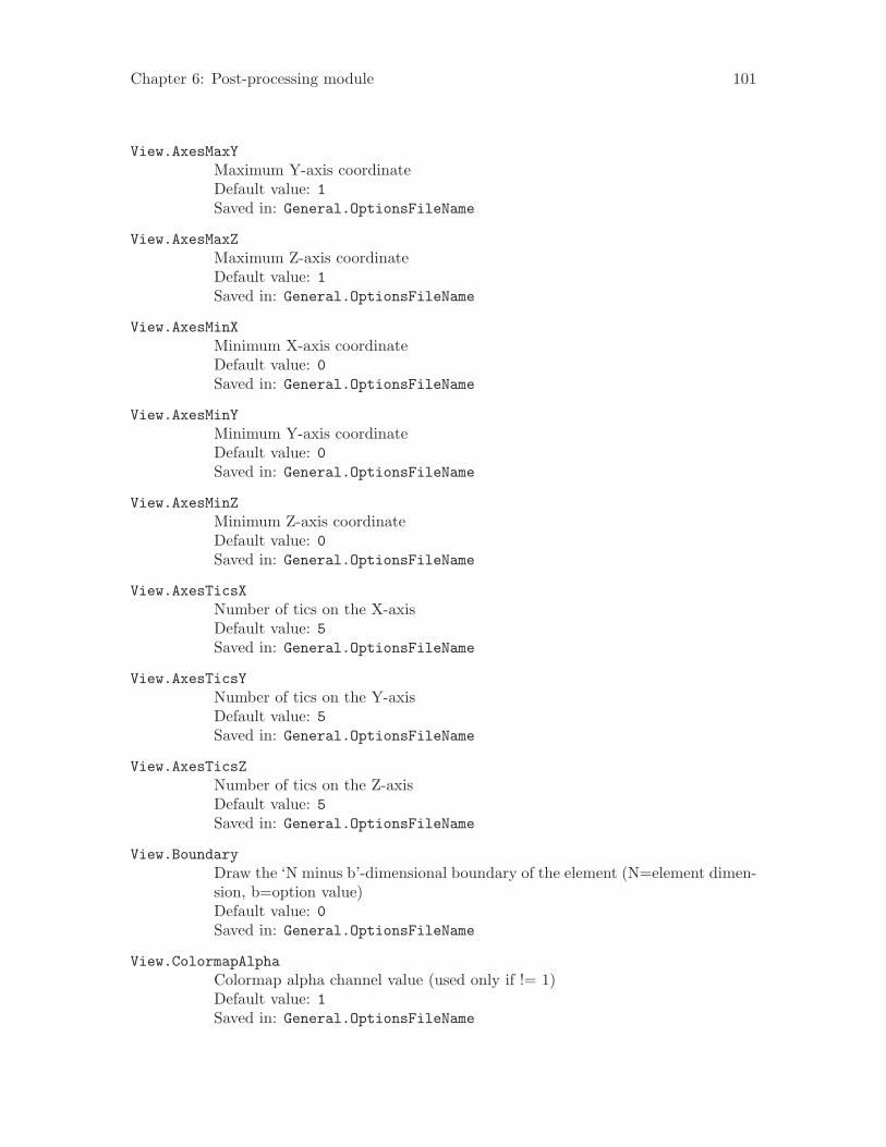
Chapter 6: Post-processing module 101
View.AxesMaxYMaximum Y-axis coordinateDefault value: 1Saved in: General.OptionsFileName
View.AxesMaxZMaximum Z-axis coordinateDefault value: 1Saved in: General.OptionsFileName
View.AxesMinXMinimum X-axis coordinateDefault value: 0Saved in: General.OptionsFileName
View.AxesMinYMinimum Y-axis coordinateDefault value: 0Saved in: General.OptionsFileName
View.AxesMinZMinimum Z-axis coordinateDefault value: 0Saved in: General.OptionsFileName
View.AxesTicsXNumber of tics on the X-axisDefault value: 5Saved in: General.OptionsFileName
View.AxesTicsYNumber of tics on the Y-axisDefault value: 5Saved in: General.OptionsFileName
View.AxesTicsZNumber of tics on the Z-axisDefault value: 5Saved in: General.OptionsFileName
View.BoundaryDraw the ‘N minus b’-dimensional boundary of the element (N=element dimen-sion, b=option value)Default value: 0Saved in: General.OptionsFileName
View.ColormapAlphaColormap alpha channel value (used only if != 1)Default value: 1Saved in: General.OptionsFileName

102 Gmsh 1.63
View.ColormapAlphaPowerColormap alpha channel powerDefault value: 0Saved in: General.OptionsFileName
View.ColormapBetaColormap beta parameter (gamma = 1-beta)Default value: 0Saved in: General.OptionsFileName
View.ColormapBiasColormap biasDefault value: 0Saved in: General.OptionsFileName
View.ColormapCurvatureColormap curvature or slope coefficientDefault value: 0Saved in: General.OptionsFileName
View.ColormapInvertInvert the color values, i.e., replace x with (255-x) in the colormap?Default value: 0Saved in: General.OptionsFileName
View.ColormapNumberDefault colormap numberDefault value: 2Saved in: General.OptionsFileName
View.ColormapRotationIncremental colormap rotationDefault value: 0Saved in: General.OptionsFileName
View.ColormapSwapSwap the min/max values in the colormap?Default value: 0Saved in: General.OptionsFileName
View.CustomMaxUser-defined maximum value to be displayedDefault value: 0Saved in: -
View.CustomMinUser-defined minimum value to be displayedDefault value: 0Saved in: -

Chapter 6: Post-processing module 103
View.DisplacementFactorDisplacement amplificationDefault value: 1Saved in: General.OptionsFileName
View.DrawHexahedraDisplay post-processing hexahedra?Default value: 1Saved in: General.OptionsFileName
View.DrawLinesDisplay post-processing lines?Default value: 1Saved in: General.OptionsFileName
View.DrawPointsDisplay post-processing points?Default value: 1Saved in: General.OptionsFileName
View.DrawPrismsDisplay post-processing prisms?Default value: 1Saved in: General.OptionsFileName
View.DrawPyramidsDisplay post-processing pyramids?Default value: 1Saved in: General.OptionsFileName
View.DrawQuadranglesDisplay post-processing quadrangles?Default value: 1Saved in: General.OptionsFileName
View.DrawScalarsDisplay scalar values?Default value: 1Saved in: General.OptionsFileName
View.DrawStringsDisplay post-processing annotation strings?Default value: 1Saved in: General.OptionsFileName
View.DrawTensorsDisplay tensor values?Default value: 1Saved in: General.OptionsFileName

104 Gmsh 1.63
View.DrawTetrahedraDisplay post-processing tetrahedra?Default value: 1Saved in: General.OptionsFileName
View.DrawTrianglesDisplay post-processing triangles?Default value: 1Saved in: General.OptionsFileName
View.DrawVectorsDisplay vector values?Default value: 1Saved in: General.OptionsFileName
View.ExplodeExplode elements (between 0=point and 1=non-transformed)Default value: 1Saved in: General.OptionsFileName
View.ExternalViewIndex of the view used to color vector fields (-1=self)Default value: -1Saved in: General.OptionsFileName
View.FakeTransparencyUse fake transparency (cheaper than the real thing, but incorrect)Default value: 0Saved in: General.OptionsFileName
View.GeneralizedRaiseFactorGeneralized raise amplification factorDefault value: 1Saved in: General.OptionsFileName
View.GeneralizedRaiseViewIndex of the view used for generalized raise (-1=self)Default value: -1Saved in: General.OptionsFileName
View.GlyphLocationGlyph (arrow, number, etc.) location (1=center of gravity, 2=node)Default value: 1Saved in: General.OptionsFileName
View.GridGrid mode (this option is deprecated: use View.Axes instead)Default value: 0Saved in: -

Chapter 6: Post-processing module 105
View.HeightHeight (in pixels) of the scale or 2D plotDefault value: 200Saved in: General.OptionsFileName
View.IntervalsTypeType of interval display (1=iso, 2=continuous, 3=discrete, 4=numeric)Default value: 2Saved in: General.OptionsFileName
View.LightEnable lighting for the viewDefault value: 1Saved in: General.OptionsFileName
View.LightLinesLight element edgesDefault value: 0Saved in: General.OptionsFileName
View.LightTwoSideLight both sides of view elements (leads to slower rendering)Default value: 1Saved in: General.OptionsFileName
View.LineTypeDisplay lines as solid color segments (0) or 3D cylinders (1)Default value: 0Saved in: General.OptionsFileName
View.LineWidthDisplay width of lines (in pixels)Default value: 1Saved in: General.OptionsFileName
View.Max Maximum value in the view (read-only)Default value: -2.22195e-146Saved in: -
View.MaxXMaximum view coordinate along the X-axis (read-only)Default value: -2.22195e-146Saved in: -
View.MaxYMaximum view coordinate along the Y-axis (read-only)Default value: -2.22195e-146Saved in: -
View.MaxZMaximum view coordinate along the Z-axis (read-only)Default value: -2.22195e-146Saved in: -

106 Gmsh 1.63
View.Min Minimum value in the view (read-only)Default value: -2.22195e-146Saved in: -
View.MinXMinimum view coordinate along the X-axis (read-only)Default value: -2.22195e-146Saved in: -
View.MinYMinimum view coordinate along the Y-axis (read-only)Default value: -2.22195e-146Saved in: -
View.MinZMinimum view coordinate along the Z-axis (read-only)Default value: -2.22195e-146Saved in: -
View.NbIsoNumber of intervalsDefault value: 15Saved in: General.OptionsFileName
View.NbTimeStepNumber of time steps in the view (do not change this!)Default value: 1Saved in: -
View.NormalsDisplay size of normal vectors (in pixels)Default value: 0Saved in: General.OptionsFileName
View.OffsetXTranslation of the view along X-axis (in model coordinates)Default value: 0Saved in: -
View.OffsetYTranslation of the view along Y-axis (in model coordinates)Default value: 0Saved in: -
View.OffsetZTranslation of the view along Z-axis (in model coordinates)Default value: 0Saved in: -
View.PointSizeDisplay size of points (in pixels)Default value: 3Saved in: General.OptionsFileName

Chapter 6: Post-processing module 107
View.PointTypeDisplay points as solid color dots (0) or 3D spheres (1)Default value: 0Saved in: General.OptionsFileName
View.PositionXHorizontal position (in pixels) of the upper left corner of the scale or 2D plotDefault value: 100Saved in: General.OptionsFileName
View.PositionYVertical position (in pixels) of the upper left corner of the scale or 2D plotDefault value: 50Saved in: General.OptionsFileName
View.RaiseXElevation of the view along X-axis (in model coordinates)Default value: 0Saved in: -
View.RaiseYElevation of the view along Y-axis (in model coordinates)Default value: 0Saved in: -
View.RaiseZElevation of the view along Z-axis (in model coordinates)Default value: 0Saved in: -
View.RangeTypeValue scale range type (1=default, 2=custom, 3=per time step)Default value: 1Saved in: General.OptionsFileName
View.SaturateValuesSaturate the view values to custom min and max (1=true, 0=false)Default value: 0Saved in: General.OptionsFileName
View.ScaleTypeValue scale type (1=linear, 2=logarithmic, 3=double logarithmic)Default value: 1Saved in: General.OptionsFileName
View.ShowElementShow element boundaries?Default value: 0Saved in: General.OptionsFileName

108 Gmsh 1.63
View.ShowScaleShow value scale?Default value: 1Saved in: General.OptionsFileName
View.ShowTimeTime display mode (0=hidden, 1=value if multiple, 2=value always, 3=step ifmultiple, 4=step always)Default value: 3Saved in: General.OptionsFileName
View.SmoothNormalsSmooth the normals?Default value: 0Saved in: General.OptionsFileName
View.StippleStipple curves in 2D plots?Default value: 0Saved in: General.OptionsFileName
View.TangentsDisplay size of tangent vectors (in pixels)Default value: 0Saved in: General.OptionsFileName
View.TensorTypeTensor Visualization TypeDefault value: 0Saved in: General.OptionsFileName
View.TimeStepCurrent time step displayedDefault value: 0Saved in: -
View.Transform11Element (1,1) of the 3x3 coordinate transformation matrixDefault value: 1Saved in: -
View.Transform12Element (1,2) of the 3x3 coordinate transformation matrixDefault value: 0Saved in: -
View.Transform13Element (1,3) of the 3x3 coordinate transformation matrixDefault value: 0Saved in: -

Chapter 6: Post-processing module 109
View.Transform21Element (2,1) of the 3x3 coordinate transformation matrixDefault value: 0Saved in: -
View.Transform22Element (2,2) of the 3x3 coordinate transformation matrixDefault value: 1Saved in: -
View.Transform23Element (2,3) of the 3x3 coordinate transformation matrixDefault value: 0Saved in: -
View.Transform31Element (3,1) of the 3x3 coordinate transformation matrixDefault value: 0Saved in: -
View.Transform32Element (3,2) of the 3x3 coordinate transformation matrixDefault value: 0Saved in: -
View.Transform33Element (3,3) of the 3x3 coordinate transformation matrixDefault value: 1Saved in: -
View.TypeType of plot (1=3D, 2=2D space, 3=2D time)Default value: 1Saved in: -
View.UseGeneralizedRaiseUse generalized raise?Default value: 0Saved in: General.OptionsFileName
View.VectorTypeVector display type (1=segment, 2=arrow, 3=pyramid, 4=3D arrow, 5=dis-placement)Default value: 4Saved in: General.OptionsFileName
View.VisibleIs the view visible?Default value: 1Saved in: -
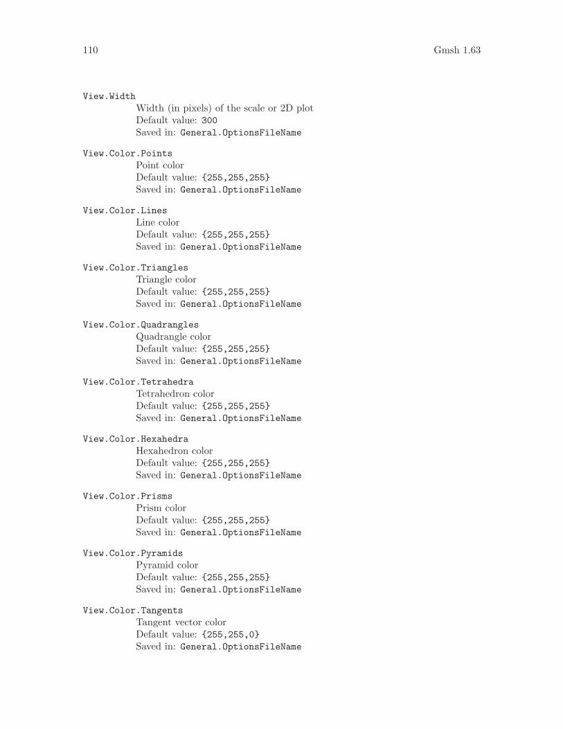
110 Gmsh 1.63
View.WidthWidth (in pixels) of the scale or 2D plotDefault value: 300Saved in: General.OptionsFileName
View.Color.PointsPoint colorDefault value: {255,255,255}Saved in: General.OptionsFileName
View.Color.LinesLine colorDefault value: {255,255,255}Saved in: General.OptionsFileName
View.Color.TrianglesTriangle colorDefault value: {255,255,255}Saved in: General.OptionsFileName
View.Color.QuadranglesQuadrangle colorDefault value: {255,255,255}Saved in: General.OptionsFileName
View.Color.TetrahedraTetrahedron colorDefault value: {255,255,255}Saved in: General.OptionsFileName
View.Color.HexahedraHexahedron colorDefault value: {255,255,255}Saved in: General.OptionsFileName
View.Color.PrismsPrism colorDefault value: {255,255,255}Saved in: General.OptionsFileName
View.Color.PyramidsPyramid colorDefault value: {255,255,255}Saved in: General.OptionsFileName
View.Color.TangentsTangent vector colorDefault value: {255,255,0}Saved in: General.OptionsFileName

Chapter 6: Post-processing module 111
View.Color.NormalsNormal vector colorDefault value: {255,0,0}Saved in: General.OptionsFileName
View.Color.Text2D2D text colorDefault value: {255,255,255}Saved in: General.OptionsFileName
View.Color.Text3D3D text colorDefault value: {255,255,255}Saved in: General.OptionsFileName
View.Color.AxesAxes colorDefault value: {255,255,255}Saved in: General.OptionsFileName
View.ColorTableColor table used to draw the viewSaved in: General.OptionsFileName

112 Gmsh 1.63

Chapter 7: Tutorial 113
7 Tutorial
The nine following examples introduce new features gradually, starting with ‘t1.geo’. Thefiles corresponding to these examples are available in the ‘tutorial’ directory of the Gmshdistribution.
This tutorial does not explain the mesh and post-processing file formats: see Chapter 9[File formats], page 145, for this.
To learn how to run Gmsh on your computer, see Chapter 8 [Running Gmsh], page 137.In addition, interactive tutorials that explain how to use the graphical user interface areavailable on Gmsh’s webpage:
• The first interactive tutorial shows how to create a simple 2D geometry and how togenerate a mesh;
• The second shows several methods to visualize data sets on deformed grids;• The third shows how to use post-processing plugins.
7.1 ‘t1.geo’
/*********************************************************************** Gmsh tutorial 1** Variables, elementary entities (points, lines, surfaces), physical* entities (points, lines, surfaces), background mesh**********************************************************************/
// The simplest construction of Gmsh’s scripting language is the// ‘affectation’. The following command defines a new variable ‘lc’:
lc = 0.009;
// This variable can then for example be used in the definition of// Gmsh’s simplest ‘elementary entity’, a ‘Point’. A Point is defined// by a list of four numbers: its three coordinates (X, Y and Z), and// a characteristic length which sets the target element size at the// point:
Point(1) = {0, 0, 0, 9.e-1 * lc};
// The actual distribution of the mesh element sizes is then obtained// by interpolation of these characteristic lengths throughout the// geometry. There are also other possibilities to specify// characteristic lengths: attractors (see ‘t7.geo’) and background// meshes (see ‘bgmesh.pos’).

114 Gmsh 1.63
// As can be seen in the previous definition, more complex expressions// can be constructed from variables and floating point// constants. Here, the product of the variable ‘lc’ by the constant// 9.e-1 is given as the fourth argument of the list defining the// point.
// We can then define some additional points as well as our first// curve. Curves are Gmsh’s second type of elementery entities, and,// amongst curves, straight lines are the simplest. A straight line is// defined by a list of point numbers. In the commands below, for// example, the line 1 starts at point 1 and ends at point 2:
Point(2) = {.1, 0, 0, lc} ;Point(3) = {.1, .3, 0, lc} ;Point(4) = {0, .3, 0, lc} ;
Line(1) = {1,2} ;Line(2) = {3,2} ;Line(3) = {3,4} ;Line(4) = {4,1} ;
// The third elementary entity is the surface. In order to define a// simple rectangular surface from the four lines defined above, a// line loop has first to be defined. A line loop is a list of// connected lines, a sign being associated with each line (depending// on the orientation of the line):
Line Loop(5) = {4,1,-2,3} ;
// We can then define the surface as a list of line loops (only one// here, since there are no holes--see ‘t4.geo’):
Plane Surface(6) = {5} ;
// At this level, Gmsh knows everything to display the rectangular// surface 6 and to mesh it. An optional step is needed if we want to// associate specific region numbers to the various elements in the// mesh (e.g. to the line segments discretizing lines 1 to 4 or to the// triangles discretizing surface 6). This is achieved by the// definition of ‘physical entities’. Physical entities will group// elements belonging to several elementary entities by giving them a// common number (a region number), and specifying their orientation.
// We can for example group the points 1 and 2 into the physical// entity 1:
Physical Point(1) = {1,2} ;

Chapter 7: Tutorial 115
// Consequently, two punctual elements will be saved in the output// files, both with the region number 1. The mechanism is identical// for line or surface elements:
Physical Line(10) = {1,2,4} ;
MySurface = 100;Physical Surface(MySurface) = {6} ;
// All the line elements created during the meshing of lines 1, 2 and// 4 will be saved in the output file with the region number 10; and// all the triangular elements resulting from the discretization of// surface 6 will be given the region number 100.
// Note that, if no physical entities are defined, all the elements in// the mesh will be directly saved with their default orientation and// with a region number equal to the number of the elementary entity// they discretize.
7.2 ‘t2.geo’
/*********************************************************************** Gmsh tutorial 2** Includes, geometrical transformations, extruded geometries,* elementary entities (volumes), physical entities (volumes)**********************************************************************/
// We first include the previous tutorial file, in order to use it as// a basis for this one:
Include "t1.geo";
// We can then add new points and lines in the same way as we did in// ‘t1.geo’:
Point(5) = {0, .4, 0, lc};Line(5) = {4, 5};
// But Gmsh also provides tools to tranform (translate, rotate, etc.)// elementary entities or copies of elementary entities. For example,// the point 3 can be moved by 0.05 units to the left with:

116 Gmsh 1.63
Translate {-0.05, 0, 0} { Point{3}; }
// The resulting point can also be duplicated and translated by 0.1// along the y axis:
tmp[] = Translate {0, 0.1, 0} { Duplicata{ Point{3}; } } ;
// In this case, we assigned the result of the Translate command to a// list, so that we can retrieve the number of the newly created point// and use it to create new lines and a new surface:
Line(7) = {3,tmp[0]};Line(8) = {tmp[0],5};Line Loop(10) = {5,-8,-7,3};Plane Surface(11) = {10};
// Of course, these transformation commands not only apply to points,// but also to lines and surfaces. We can for example translate a copy// of surface 6 by 0.12 units along the z axis and define some// additional lines and surfaces with:
h = 0.12;Translate {0, 0, h} { Duplicata{ Surface{6}; } }
Line(106) = {1,8};Line(107) = {2,12};Line(108) = {3,16};Line(109) = {4,7};
Line Loop(110) = {1,107,-103,-106}; Plane Surface(111) = {110};Line Loop(112) = {2,107,104,-108}; Plane Surface(113) = {112};Line Loop(114) = {3,109,-105,-108}; Plane Surface(115) = {114};Line Loop(116) = {4,106,-102,-109}; Plane Surface(117) = {116};
// Volumes are the fourth type of elementary entities in Gmsh. In the// same way one defines line loops to build surfaces, one has to// define surface loops (i.e. ‘shells’) to build volumes. The// following volume does not have holes and thus consists of a single// surface loop:
Surface Loop(118) = {117,-6,111,-113,101,115};Volume(119) = {118};
// Another way to define a volume is by extruding a surface. The// following command extrudes the surface 11 along the z axis and// automatically creates a new volume:

Chapter 7: Tutorial 117
Extrude {0, 0, h} { Surface{11}; }
// All these geometrical transformations automatically generate new// elementary entities. The following command permits to manually// specify a characteristic length for some of the new points:
Characteristic Length {tmp[0], 2, 12, 3, 16, 6, 22} = lc * 4;
// Note that, if the transformation tools are handy to create complex// geometries, it is also sometimes useful to generate the ‘flat’// geometry, with an explicit list of all elementary entities. This// can be achieved by selecting the ‘File->Save as->Gmsh unrolled// geometry’ menu or by typing//// > gmsh t2.geo -0//// on the command line.
// To save all the tetrahedra discretizing the volumes 119 and 120// with a common region number, we finally define a physical// volume:
Physical Volume (1) = {119,120};
7.3 ‘t3.geo’
/*********************************************************************** Gmsh tutorial 3** Extruded meshes, options**********************************************************************/
// Again, we start by including the first tutorial:
Include "t1.geo";
// As in ‘t2.geo’, we plan to perform an extrusion along the z axis.// But here, instead of only extruding the geometry, we also want to// extrude the 2D mesh. This is done with the same ‘Extrude’ command,// but by specifying the number of layers (4 in this case, with 8, 4,// 2 and 1 subdivisions, respectively), with volume numbers 9000 to// 9003 and respective heights equal to h/4:
h = 0.1;

118 Gmsh 1.63
Extrude {0,0,h} {Surface{6}; Layers{ {8,4,2,1}, {9000:9003}, {0.25,0.5,0.75,1} };
}
// The extrusion can also be performed with a rotation instead of a// translation, and the resulting mesh can be recombined into prisms// (wedges). All rotations are specified by an axis direction// ({0,1,0}), an axis point ({-0.1,0,0.1}) and a rotation angle// (-Pi/2):
Extrude { {0,1,0} , {-0.1,0,0.1} , -Pi/2 } {Surface{122}; Layers { 7, 9004, 1 }; Recombine;
}
// Note that a translation ({-2*h,0,0}) and a rotation ({1,0,0},// {0,0.15,0.25}, Pi/2) can also be combined:
aa[] = Extrude { {-2*h,0,0}, {1,0,0} , {0,0.15,0.25} , Pi/2 } {Surface{news-1}; Layers{ 10, 1 }; Recombine;
};
// In this last extrusion command we didn’t specify an explicit// volume number (which is equivalent to setting it to "0"),// which means that the elements will simply belong the automatically// created volume (whose number we get from the aa[] list).
// We finally define a new physical volume to save all the tetrahedra// with a common region number (101):
Physical Volume(101) = {9000:9004, aa[1]};
// Let us now change some options... Since all interactive options are// accessible in Gmsh’s scripting language, we can for example define// a global characteristic length factor, redefine some background// colors, disable the display of the axes, and select an initial// viewpoint in XYZ mode (disabling the interactive trackball-like// rotation mode) directly in the input file:
Mesh.CharacteristicLengthFactor = 4;General.Color.Background = {120,120,120};General.Color.Foreground = {255,255,255};General.Color.Text = White;Geometry.Color.Points = Orange;General.Axes = 0;General.Trackball = 0;General.RotationCenterGravity = 0;

Chapter 7: Tutorial 119
General.RotationCenterX = 0;General.RotationCenterY = 0;General.RotationCenterZ = 0;General.RotationX = 10;General.RotationY = 70;General.TranslationX = -0.2;
// Note that all colors can be defined literally or numerically, i.e.// ‘General.Color.Background = Red’ is equivalent to// ‘General.Color.Background = {255,0,0}’; and also note that, as with// user-defined variables, the options can be used either as right or// left hand sides, so that the following command will set the surface// color to the same color as the points:
Geometry.Color.Surfaces = Geometry.Color.Points;
// You can click on the ‘?’ button in the status bar of the graphic// window to see the current values of all options. To save all the// options in a file, you can use the ‘File->Save as->Gmsh options’// menu. To save the current options as the default options for all// future Gmsh sessions, you should use the ‘Tools->Options->Save’// button.
7.4 ‘t4.geo’
/*********************************************************************** Gmsh tutorial 4** Built-in functions, holes, strings, mesh color**********************************************************************/
// As usual, we start by defining some variables, some points and some// lines:
cm = 1e-02;
e1 = 4.5*cm; e2 = 6*cm / 2; e3 = 5*cm / 2;
h1 = 5*cm; h2 = 10*cm; h3 = 5*cm; h4 = 2*cm; h5 = 4.5*cm;
R1 = 1*cm; R2 = 1.5*cm; r = 1*cm;
ccos = ( -h5*R1 + e2 * Hypot(h5,Hypot(e2,R1)) ) / (h5^2 + e2^2);ssin = Sqrt(1-ccos^2);

120 Gmsh 1.63
Lc1 = 0.01;Lc2 = 0.003;
Point(1) = { -e1-e2, 0.0 , 0.0 , Lc1};Point(2) = { -e1-e2, h1 , 0.0 , Lc1};Point(3) = { -e3-r , h1 , 0.0 , Lc2};Point(4) = { -e3-r , h1+r , 0.0 , Lc2};Point(5) = { -e3 , h1+r , 0.0 , Lc2};Point(6) = { -e3 , h1+h2, 0.0 , Lc1};Point(7) = { e3 , h1+h2, 0.0 , Lc1};Point(8) = { e3 , h1+r , 0.0 , Lc2};Point(9) = { e3+r , h1+r , 0.0 , Lc2};Point(10)= { e3+r , h1 , 0.0 , Lc2};Point(11)= { e1+e2, h1 , 0.0 , Lc1};Point(12)= { e1+e2, 0.0 , 0.0 , Lc1};Point(13)= { e2 , 0.0 , 0.0 , Lc1};
Point(14)= { R1 / ssin , h5+R1*ccos, 0.0 , Lc2};Point(15)= { 0.0 , h5 , 0.0 , Lc2};Point(16)= { -R1 / ssin , h5+R1*ccos, 0.0 , Lc2};Point(17)= { -e2 , 0.0 , 0.0 , Lc1};
Point(18)= { -R2 , h1+h3 , 0.0 , Lc2};Point(19)= { -R2 , h1+h3+h4, 0.0 , Lc2};Point(20)= { 0.0 , h1+h3+h4, 0.0 , Lc2};Point(21)= { R2 , h1+h3+h4, 0.0 , Lc2};Point(22)= { R2 , h1+h3 , 0.0 , Lc2};Point(23)= { 0.0 , h1+h3 , 0.0 , Lc2};
Point(24)= { 0 , h1+h3+h4+R2, 0.0 , Lc2};Point(25)= { 0 , h1+h3-R2, 0.0 , Lc2};
Line(1) = {1 ,17};Line(2) = {17,16};
// Since not all curves are straight lines, Gmsh provides many other// curve primitives: splines, B-splines, circle arcs, ellipse arcs,// etc. Here we define a new circle arc, starting at point 14 and// ending at point 16, with the circle’s center being the point 15:
Circle(3) = {14,15,16};
// Note that, in Gmsh, circle arcs should always be stricly smaller// than Pi. We can then define additional lines and circles, as well// as a new surface:

Chapter 7: Tutorial 121
Line(4) = {14,13};Line(5) = {13,12};Line(6) = {12,11};Line(7) = {11,10};Circle(8) = { 8, 9,10};Line(9) = { 8, 7};Line(10) = { 7, 6};Line(11) = { 6, 5};Circle(12) = { 3, 4, 5};Line(13) = { 3, 2};Line(14) = { 2, 1};Line(15) = {18,19};Circle(16) = {21,20,24};Circle(17) = {24,20,19};Circle(18) = {18,23,25};Circle(19) = {25,23,22};Line(20) = {21,22};
Line Loop(21) = {17,-15,18,19,-20,16};Plane Surface(22) = {21};
// But we still need to define the exterior surface. Since it has a// hole, its definition now requires two lines loops:
Line Loop(23) = {11,-12,13,14,1,2,-3,4,5,6,7,-8,9,10};Plane Surface(24) = {23,21};
// Finally, we can add some comments by embedding a post-processing// view containing some strings, and change the color of some mesh// entities:
View "comments" {// 10 pixels from the left and 15 pixels from the top of the graphic// window:T2(10,15,0){StrCat("File created on ", Today)};
// 10 pixels from the left and 10 pixels from the bottom of the// graphic window:T2(10,-10,0){"Copyright (C) My Company"};
// in the model, at (X,Y,Z) = (0.0,0.11,0.0):T3(0,0.11,0,0){"Hole"};
};
Color Grey70{ Surface{ 22 }; }Color Purple{ Surface{ 24 }; }Color Red{ Line{ 1:14 }; }

122 Gmsh 1.63
Color Yellow{ Line{ 15:20 }; }
7.5 ‘t5.geo’
/*********************************************************************** Gmsh tutorial 5** Characteristic lengths, arrays of variables, functions, loops**********************************************************************/
// Again, we start be defining some characteristic lengths:
lcar1 = .1;lcar2 = .0005;lcar3 = .055;
// If we wanted to change these lengths globally (without changing the// above definitions), we could give a global scaling factor for all// characteristic lengths on the command line with the ‘-clscale’// option (or with ‘Mesh.CharacteristicLengthFactor’ in an option// file). For example, with://// > gmsh t5 -clscale 1//// this input file produces a mesh of approximately 2,500 nodes and// 13,000 tetrahedra (in 4 seconds on a 1.2GHz PC). With//// > gmsh t5 -clscale 0.2//// (i.e. with all characteristic lengths divided by 5), the mesh// counts approximately 260,000 nodes and 1.6 million tetrahedra (and// the computation takes 16 minutes on the same machine).
// Let us proceed by defining some elementary entities describing a// truncated cube:
Point(1) = {0.5,0.5,0.5,lcar2}; Point(2) = {0.5,0.5,0,lcar1};Point(3) = {0,0.5,0.5,lcar1}; Point(4) = {0,0,0.5,lcar1};Point(5) = {0.5,0,0.5,lcar1}; Point(6) = {0.5,0,0,lcar1};Point(7) = {0,0.5,0,lcar1}; Point(8) = {0,1,0,lcar1};Point(9) = {1,1,0,lcar1}; Point(10) = {0,0,1,lcar1};Point(11) = {0,1,1,lcar1}; Point(12) = {1,1,1,lcar1};Point(13) = {1,0,1,lcar1}; Point(14) = {1,0,0,lcar1};

Chapter 7: Tutorial 123
Line(1) = {8,9}; Line(2) = {9,12}; Line(3) = {12,11};Line(4) = {11,8}; Line(5) = {9,14}; Line(6) = {14,13};Line(7) = {13,12}; Line(8) = {11,10}; Line(9) = {10,13};Line(10) = {10,4}; Line(11) = {4,5}; Line(12) = {5,6};Line(13) = {6,2}; Line(14) = {2,1}; Line(15) = {1,3};Line(16) = {3,7}; Line(17) = {7,2}; Line(18) = {3,4};Line(19) = {5,1}; Line(20) = {7,8}; Line(21) = {6,14};
Line Loop(22) = {-11,-19,-15,-18}; Plane Surface(23) = {22};Line Loop(24) = {16,17,14,15}; Plane Surface(25) = {24};Line Loop(26) = {-17,20,1,5,-21,13}; Plane Surface(27) = {26};Line Loop(28) = {-4,-1,-2,-3}; Plane Surface(29) = {28};Line Loop(30) = {-7,2,-5,-6}; Plane Surface(31) = {30};Line Loop(32) = {6,-9,10,11,12,21}; Plane Surface(33) = {32};Line Loop(34) = {7,3,8,9}; Plane Surface(35) = {34};Line Loop(36) = {-10,18,-16,-20,4,-8}; Plane Surface(37) = {36};Line Loop(38) = {-14,-13,-12,19}; Plane Surface(39) = {38};
// Instead of using included files, let us now use a user-defined// function in order to carve some holes in the cube:
Function CheeseHole
// In the following commands we use the reserved variable name// ‘newp’, which automatically selects a new point number. This// number is chosen as the highest current point number, plus// one. (Note that, analogously to ‘newp’, the variables ‘newc’,// ‘news’, ‘newv’ and ‘newreg’ select the highest number amongst// currently defined curves, surfaces, volumes and ‘any entities// other than points’, respectively.)
p1 = newp; Point(p1) = {x, y, z, lcar3} ;p2 = newp; Point(p2) = {x+r,y, z, lcar3} ;p3 = newp; Point(p3) = {x, y+r,z, lcar3} ;p4 = newp; Point(p4) = {x, y, z+r,lcar3} ;p5 = newp; Point(p5) = {x-r,y, z, lcar3} ;p6 = newp; Point(p6) = {x, y-r,z, lcar3} ;p7 = newp; Point(p7) = {x, y, z-r,lcar3} ;
c1 = newreg; Circle(c1) = {p2,p1,p7};c2 = newreg; Circle(c2) = {p7,p1,p5};c3 = newreg; Circle(c3) = {p5,p1,p4};c4 = newreg; Circle(c4) = {p4,p1,p2};c5 = newreg; Circle(c5) = {p2,p1,p3};c6 = newreg; Circle(c6) = {p3,p1,p5};c7 = newreg; Circle(c7) = {p5,p1,p6};c8 = newreg; Circle(c8) = {p6,p1,p2};

124 Gmsh 1.63
c9 = newreg; Circle(c9) = {p7,p1,p3};c10 = newreg; Circle(c10) = {p3,p1,p4};c11 = newreg; Circle(c11) = {p4,p1,p6};c12 = newreg; Circle(c12) = {p6,p1,p7};
// We need non-plane surfaces to define the spherical cheese// holes. Here we use ruled surfaces, which can have 3 or 4// sides:
l1 = newreg; Line Loop(l1) = {c5,c10,c4}; Ruled Surface(newreg) = {l1};l2 = newreg; Line Loop(l2) = {c9,-c5,c1}; Ruled Surface(newreg) = {l2};l3 = newreg; Line Loop(l3) = {c12,-c8,-c1}; Ruled Surface(newreg) = {l3};l4 = newreg; Line Loop(l4) = {c8,-c4,c11}; Ruled Surface(newreg) = {l4};l5 = newreg; Line Loop(l5) = {-c10,c6,c3}; Ruled Surface(newreg) = {l5};l6 = newreg; Line Loop(l6) = {-c11,-c3,c7}; Ruled Surface(newreg) = {l6};l7 = newreg; Line Loop(l7) = {-c2,-c7,-c12};Ruled Surface(newreg) = {l7};l8 = newreg; Line Loop(l8) = {-c6,-c9,c2}; Ruled Surface(newreg) = {l8};
// Please note that all surface meshes are generated by projecting a// 2D planar mesh onto the surface, and that this method gives nice// results only if the surface’s curvature is small enough. If not,// you will have to cut the surface in pieces.
// We then use an array of variables to store the surface loops// identification numbers for later reference (we will need these to// define the final volume):
theloops[t] = newreg ;
Surface Loop(theloops[t]) = {l8+1,l5+1,l1+1,l2+1,l3+1,l7+1,l6+1,l4+1};
thehole = newreg ;Volume(thehole) = theloops[t] ;
Return
// We can use a ‘For’ loop to generate five holes in the cube:
x = 0 ; y = 0.75 ; z = 0 ; r = 0.09 ;
For t In {1:5}
x += 0.166 ;z += 0.166 ;
Call CheeseHole ;

Chapter 7: Tutorial 125
// We define a physical volume for each hole:
Physical Volume (t) = thehole ;
// We also print some variables on the terminal (note that, since// all variables are treated internally as floating point numbers,// the format string should only contain valid floating point format// specifiers):
Printf("Hole %g (center = {%g,%g,%g}, radius = %g) has number %g!",t, x, y, z, r, thehole) ;
EndFor
// We can then define the surface loop for the exterior surface of the// cube:
theloops[0] = newreg ;
Surface Loop(theloops[0]) = {35,31,29,37,33,23,39,25,27} ;
// The volume of the cube, without the 5 cheese holes, is now defined// by 6 surface loops (the exterior surface and the five interior// loops). To reference an array of variables, its identifier is// followed by ’[]’:
Volume(186) = {theloops[]} ;
// We finally define a physical volume for the elements discretizing// the cube, without the holes (whose elements were already tagged// with numbers 1 to 5 in the ‘For’ loop):
Physical Volume (10) = 186 ;
7.6 ‘t6.geo’
/*********************************************************************** Gmsh tutorial 6** Transfinite meshes**********************************************************************/
// We start by defining a more complex geometry, using the same// commands as in the previous examples:

126 Gmsh 1.63
r_int = 0.05 ;r_ext = 0.051 ;r_far = 0.125 ;r_inf = 0.4 ;phi1 = 30. * (Pi/180.) ;angl = 45. * (Pi/180.) ;
nbpt_phi = 5 ; nbpt_int = 20 ;nbpt_arc1 = 10 ; nbpt_arc2 = 10 ;nbpt_shell = 10 ; nbpt_far = 25 ; nbpt_inf = 15 ;
lc0 = 0.1 ; lc1 = 0.1 ; lc2 = 0.3 ;
Point(1) = {0, 0, 0, lc0} ;Point(2) = {r_int, 0, 0, lc0} ;Point(3) = {r_ext, 0, 0, lc1} ;Point(4) = {r_far, 0, 0, lc2} ;Point(5) = {r_inf, 0, 0, lc2} ;Point(6) = {0, 0, r_int, lc0} ;Point(7) = {0, 0, r_ext, lc1} ;Point(8) = {0, 0, r_far, lc2} ;Point(9) = {0, 0, r_inf, lc2} ;
Point(10) = {r_int*Cos(phi1), r_int*Sin(phi1), 0, lc0} ;Point(11) = {r_ext*Cos(phi1), r_ext*Sin(phi1), 0, lc1} ;Point(12) = {r_far*Cos(phi1), r_far*Sin(phi1), 0, lc2} ;Point(13) = {r_inf*Cos(phi1), r_inf*Sin(phi1), 0, lc2} ;
Point(14) = {r_int/2, 0, 0, lc2} ;Point(15) = {r_int/2*Cos(phi1), r_int/2*Sin(phi1), 0, lc2} ;Point(16) = {r_int/2, 0, r_int/2, lc2} ;Point(17) = {r_int/2*Cos(phi1), r_int/2*Sin(phi1), r_int/2, lc2} ;Point(18) = {0, 0, r_int/2, lc2} ;Point(19) = {r_int*Cos(angl), 0, r_int*Sin(angl), lc2} ;Point(20) = {r_int*Cos(angl)*Cos(phi1), r_int*Cos(angl)*Sin(phi1),
r_int*Sin(angl), lc2} ;Point(21) = {r_ext*Cos(angl), 0, r_ext*Sin(angl), lc2} ;Point(22) = {r_ext*Cos(angl)*Cos(phi1), r_ext*Cos(angl)*Sin(phi1),
r_ext*Sin(angl), lc2} ;Point(23) = {r_far*Cos(angl), 0, r_far*Sin(angl), lc2} ;Point(24) = {r_far*Cos(angl)*Cos(phi1), r_far*Cos(angl)*Sin(phi1),
r_far*Sin(angl), lc2} ;Point(25) = {r_inf, 0, r_inf, lc2} ;Point(26) = {r_inf*Cos(phi1), r_inf*Sin(phi1), r_inf, lc2} ;
Circle(1) = {2,1,19}; Circle(2) = {19,1,6}; Circle(3) = {3,1,21};

Chapter 7: Tutorial 127
Circle(4) = {21,1,7}; Circle(5) = {4,1,23}; Circle(6) = {23,1,8};Line(7) = {5,25}; Line(8) = {25,9};Circle(9) = {10,1,20}; Circle(10)= {20,1,6}; Circle(11) = {11,1,22};Circle(12)= {22,1,7}; Circle(13)= {12,1,24}; Circle(14) = {24,1,8};Line(15) = {13,26}; Line(16) = {26,9};Circle(17)= {19,1,20}; Circle(18)= {21,1,22}; Circle(19) = {23,1,24};Circle(20)= {25,1,26}; Circle(21)= {2,1,10}; Circle(22) = {3,1,11};Circle(23)= {4,1,12}; Circle(24)= {5,1,13};
Line(25) = {1,14}; Line(26) = {14,2}; Line(27) = {2,3};Line(28) = {3,4}; Line(29) = {4,5}; Line(30) = {1,15};Line(31) = {15,10}; Line(32) = {10,11}; Line(33) = {11,12};Line(34) = {12,13}; Line(35) = {14,15}; Line(36) = {14,16};Line(37) = {15,17}; Line(38) = {16,17}; Line(39) = {18,16};Line(40) = {18,17}; Line(41) = {1,18}; Line(42) = {18,6};Line(43) = {6,7}; Line(44) = {16,19}; Line(45) = {19,21};Line(46) = {21,23}; Line(47) = {23,25}; Line(48) = {17,20};Line(49) = {20,22}; Line(50) = {22,24}; Line(51) = {24,26};Line(52) = {7,8}; Line(53) = {8,9};
Line Loop(54) = {39,-36,-25,41}; Ruled Surface(55) = {54};Line Loop(56) = {44,-1,-26,36}; Ruled Surface(57) = {56};Line Loop(58) = {3,-45,-1,27}; Ruled Surface(59) = {58};Line Loop(60) = {5,-46,-3,28}; Ruled Surface(61) = {60};Line Loop(62) = {7,-47,-5,29}; Ruled Surface(63) = {62};Line Loop(64) = {-2,-44,-39,42}; Ruled Surface(65) = {64};Line Loop(66) = {-4,-45,2,43}; Ruled Surface(67) = {66};Line Loop(68) = {-6,-46,4,52}; Ruled Surface(69) = {68};Line Loop(70) = {-8,-47,6,53}; Ruled Surface(71) = {70};Line Loop(72) = {-40,-41,30,37}; Ruled Surface(73) = {72};Line Loop(74) = {48,-9,-31,37}; Ruled Surface(75) = {74};Line Loop(76) = {49,-11,-32,9}; Ruled Surface(77) = {76};Line Loop(78) = {-50,-11,33,13}; Ruled Surface(79) = {78};Line Loop(80) = {-51,-13,34,15}; Ruled Surface(81) = {80};Line Loop(82) = {10,-42,40,48}; Ruled Surface(83) = {82};Line Loop(84) = {12,-43,-10,49}; Ruled Surface(85) = {84};Line Loop(86) = {14,-52,-12,50}; Ruled Surface(87) = {86};Line Loop(88) = {16,-53,-14,51}; Ruled Surface(89) = {88};Line Loop(90) = {-30,25,35}; Ruled Surface(91) = {90};Line Loop(92) = {-40,39,38}; Ruled Surface(93) = {92};Line Loop(94) = {37,-38,-36,35}; Ruled Surface(95) = {94};Line Loop(96) = {-48,-38,44,17}; Ruled Surface(97) = {96};Line Loop(98) = {18,-49,-17,45}; Ruled Surface(99) = {98};Line Loop(100) = {19,-50,-18,46}; Ruled Surface(101) = {100};Line Loop(102) = {20,-51,-19,47}; Ruled Surface(103) = {102};Line Loop(104) = {-2,17,10}; Ruled Surface(105) = {104};Line Loop(106) = {-9,-21,1,17}; Ruled Surface(107) = {106};

128 Gmsh 1.63
Line Loop(108) = {-4,18,12}; Ruled Surface(109) = {108};Line Loop(110) = {-11,-22,3,18}; Ruled Surface(111) = {110};Line Loop(112) = {-13,-23,5,19}; Ruled Surface(113) = {112};Line Loop(114) = {-6,19,14}; Ruled Surface(115) = {114};Line Loop(116) = {-15,-24,7,20}; Ruled Surface(117) = {116};Line Loop(118) = {-8,20,16}; Ruled Surface(119) = {118};Line Loop(120) = {-31,-35,26,21}; Ruled Surface(121) = {120};Line Loop(122) = {32,-22,-27,21}; Ruled Surface(123) = {122};Line Loop(124) = {33,-23,-28,22}; Ruled Surface(125) = {124};Line Loop(126) = {34,-24,-29,23}; Ruled Surface(127) = {126};
Surface Loop(128) = {93,-73,-55,95,-91};Volume(129) = {128}; // intSurface Loop(130) = {107,-75,-97,95,57,121};Volume(131) = {130}; // int bSurface Loop(132) = {105,-65,-97,-83,-93};Volume(133) = {132}; // int hSurface Loop(134) = {99,-111,77,123,59,107};Volume(135) = {134}; // shell bSurface Loop(136) = {99,-109,67,105,85};Volume(137) = {136}; // shell hSurface Loop(138) = {113,79,-101,-111,-125,-61};Volume(139) = {138}; // ext bSurface Loop(140) = {115,-69,-101,-87,-109};Volume(141) = {140}; // ext hSurface Loop(142) = {103,-117,-81,113,127,63};Volume(143) = {142}; // inf bSurface Loop(144) = {89,-119,71,103,115};Volume(145) = {144}; // inf h
// Once the geometry is defined, we then add transfinite mesh commands// in order to explicitly define a structured mesh.
// 1. Transfinite line commands specify the number of points on the// curves and their distribution (‘Progression 2’ means that each line// element in the series will be twice as long as the preceding one):
Transfinite Line{35,21,22,23,24,38,17,18,19,20} = nbpt_phi ;Transfinite Line{31,26,48,44,42} = nbpt_int Using Progression 0.88;Transfinite Line{41,37,36,9,11,1,3,13,5,15,7} = nbpt_arc1 ;Transfinite Line{30,25,40,39,10,2,12,4,14,6,16,8} = nbpt_arc2 ;Transfinite Line{32,27,49,45,43} = nbpt_shell ;Transfinite Line{33,28,46,50,52} = nbpt_far Using Progression 1.2 ;Transfinite Line{34,29,51,47,53} = nbpt_inf Using Progression 1.05;
// 2. Transfinite surfaces are defined by an ordered list of the// points on their boundary (the ordering of these points defines the

Chapter 7: Tutorial 129
// ordering of the mesh elements). Note that a transfinite surface can// only have 3 or 4 sides:
Transfinite Surface{55} = {1,14,16,18};Transfinite Surface{57} = {14,2,19,16};Transfinite Surface{59} = {2,3,21,19};Transfinite Surface{61} = {3,4,23,21};Transfinite Surface{63} = {4,5,25,23};Transfinite Surface{73} = {1,15,17,18};Transfinite Surface{75} = {15,10,20,17};Transfinite Surface{77} = {10,11,22,20};Transfinite Surface{79} = {11,12,24,22};Transfinite Surface{81} = {12,13,26,24};Transfinite Surface{65} = {18,16,19,6};Transfinite Surface{67} = {6,19,21,7};Transfinite Surface{69} = {7,21,23,8};Transfinite Surface{71} = {8,23,25,9};Transfinite Surface{83} = {17,18,6,20};Transfinite Surface{85} = {20,6,7,22};Transfinite Surface{87} = {22,7,8,24};Transfinite Surface{89} = {24,8,9,26};Transfinite Surface{91} = {1,14,15};Transfinite Surface{95} = {15,14,16,17};Transfinite Surface{93} = {18,16,17};Transfinite Surface{121} = {15,14,2,10};Transfinite Surface{97} = {17,16,19,20};Transfinite Surface{123} = {10,2,3,11};Transfinite Surface{99} = {20,19,21,22};Transfinite Surface{107} = {10,2,19,20};Transfinite Surface{105} = {6,20,19};Transfinite Surface{109} = {7,22,21};Transfinite Surface{111} = {11,3,21,22};Transfinite Surface{101} = {22,21,23,24};Transfinite Surface{125} = {11,3,4,12};Transfinite Surface{115} = {8,24,23};Transfinite Surface{113} = {24,12,4,23};Transfinite Surface{127} = {12,13,5,4};Transfinite Surface{103} = {24,23,25,26};Transfinite Surface{119} = {9,26,25};Transfinite Surface{117} = {13,5,25,26};
// 3. Transfinite volumes are also defined by an ordered list of the// points on their boundary (the ordering defines the ordering of the// mesh elements). A transfinite volume can only have 6 or 8 faces:
Transfinite Volume{129} = {1,14,15,18,16,17};Transfinite Volume{131} = {17,16,14,15,20,19,2,10};

130 Gmsh 1.63
Transfinite Volume{133} = {18,17,16,6,20,19};Transfinite Volume{135} = {10,2,19,20,11,3,21,22};Transfinite Volume{137} = {6,20,19,7,22,21};Transfinite Volume{139} = {11,3,4,12,22,21,23,24};Transfinite Volume{141} = {7,22,21,8,24,23};Transfinite Volume{143} = {12,4,5,13,24,23,25,26};Transfinite Volume{145} = {8,24,23,9,26,25};
// As with Extruded meshes, the ‘Recombine’ command tells Gmsh to// recombine the simplices into quadrangles, prisms or hexahedra when// possible:
Recombine Surface {55:127};
// We finish by defing some physical entities:
VolInt = 1000 ;SurfIntPhi0 = 1001 ; SurfIntPhi1 = 1002 ;SurfIntZ0 = 1003 ;
VolShell = 2000 ;SurfShellInt = 2001 ; SurfShellExt = 2002 ;SurfShellPhi0 = 2003 ; SurfShellPhi1 = 2004 ;SurfShellZ0 = 2005 ;LineShellIntPhi0 = 2006 ;LineShellIntPhi1 = 2007 ; LineShellIntZ0 = 2008 ;PointShellInt = 2009 ;
VolExt = 3000 ;VolInf = 3001 ;SurfInf = 3002 ;SurfExtInfPhi0 = 3003 ; SurfExtInfPhi1 = 3004 ;SurfExtInfZ0 = 3005 ;SurfInfRight = 3006 ;SurfInfTop = 3007 ;
Physical Volume (VolInt) = {129,131,133} ;Physical Surface (SurfIntPhi0) = {55,57,65} ;Physical Surface (SurfIntPhi1) = {73,75,83} ;Physical Surface (SurfIntZ0) = {91,121} ;
Physical Volume (VolShell) = {135,137} ;Physical Surface (SurfShellInt) = {105,107} ;Physical Surface (SurfShellExt) = {109,111} ;Physical Surface (SurfShellPhi0) = {59,67} ;Physical Surface (SurfShellPhi1) = {77,85} ;Physical Surface (SurfShellZ0) = {123} ;

Chapter 7: Tutorial 131
Physical Line (LineShellIntPhi0) = {1,2} ;Physical Line (LineShellIntPhi1) = {9,10} ;Physical Line (LineShellIntZ0) = 21 ;//Physical Point (PointShellInt) = 6 ;
Physical Volume (VolExt) = {139,141} ;Physical Volume (VolInf) = {143,145} ;Physical Surface (SurfExtInfPhi0) = {61,63,69,71} ;Physical Surface (SurfExtInfPhi1) = {79,87,81,89} ;Physical Surface (SurfExtInfZ0) = {125,127} ;Physical Surface (SurfInfRight) = {117} ;Physical Surface (SurfInfTop) = {119} ;
7.7 ‘t7.geo’
/*********************************************************************** Gmsh tutorial 7** Anisotropic meshes, attractors**********************************************************************/
// The anisotropic 2D mesh generator can be selected with:
Mesh.Algorithm = 2 ;
// One can force a 4 step Laplacian smoothing of the mesh with:
Mesh.Smoothing = 4 ;
lc = .1;
Point(1) = {0.0,0.0,0,lc};Point(2) = {1.2,-0.2,0,lc};Point(3) = {1,1,0,lc};Point(4) = {0,1,0,lc};
Line(1) = {3,2};Line(2) = {2,1};Line(3) = {1,4};Line(4) = {4,3};
Line Loop(5) = {1,2,3,4};Plane Surface(6) = {5};

132 Gmsh 1.63
Point(5) = {0.1,0.2,0,lc};Point(11) = {0.4,0.7,-1,lc};Point(12) = {0.5,0.5,0,lc};Point(22) = {0.9,0.9,1,lc};
Line(5) = {11,22};
Spline(7) = {4,5,12,2};
// Isotropic and anisotropic attractors can be defined on points and// lines (this is still experimental and known to be unstable: use at// your own risk!):
Attractor Point{1} = {0.01, 0.01, 2};
Attractor Line{5} = {0.3, 0.01, 2};
Attractor Line{7} = {0.1, 0.02, 8};
7.8 ‘t8.geo’
/*********************************************************************** Gmsh tutorial 8** Post-processing, scripting, animations, options**********************************************************************/
// We first include ‘t1.geo’ as well as some post-processing views:
Include "t1.geo" ;Include "view1.pos" ;Include "view1.pos" ;Include "view4.pos" ;
// We then set some general options:
General.Trackball = 0 ;General.RotationX = 0 ;General.RotationY = 0 ;General.RotationZ = 0 ;General.Color.Background = White ;General.Color.Foreground = Black ;General.Color.Text = Black ;
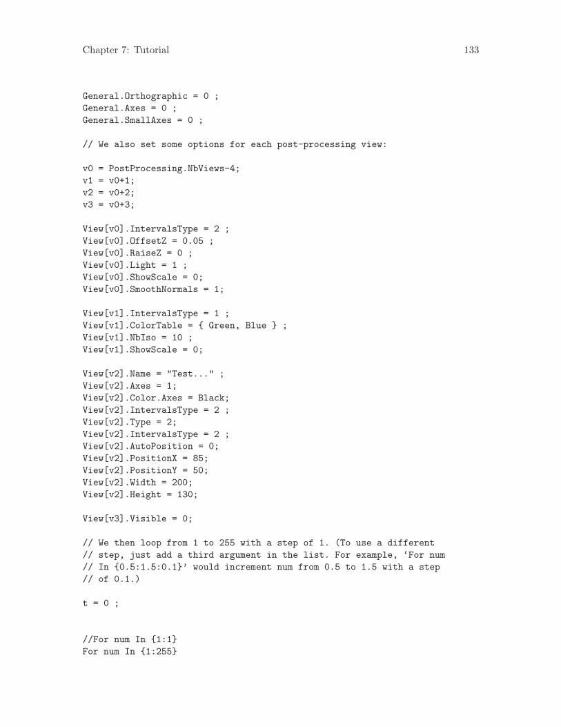
Chapter 7: Tutorial 133
General.Orthographic = 0 ;General.Axes = 0 ;General.SmallAxes = 0 ;
// We also set some options for each post-processing view:
v0 = PostProcessing.NbViews-4;v1 = v0+1;v2 = v0+2;v3 = v0+3;
View[v0].IntervalsType = 2 ;View[v0].OffsetZ = 0.05 ;View[v0].RaiseZ = 0 ;View[v0].Light = 1 ;View[v0].ShowScale = 0;View[v0].SmoothNormals = 1;
View[v1].IntervalsType = 1 ;View[v1].ColorTable = { Green, Blue } ;View[v1].NbIso = 10 ;View[v1].ShowScale = 0;
View[v2].Name = "Test..." ;View[v2].Axes = 1;View[v2].Color.Axes = Black;View[v2].IntervalsType = 2 ;View[v2].Type = 2;View[v2].IntervalsType = 2 ;View[v2].AutoPosition = 0;View[v2].PositionX = 85;View[v2].PositionY = 50;View[v2].Width = 200;View[v2].Height = 130;
View[v3].Visible = 0;
// We then loop from 1 to 255 with a step of 1. (To use a different// step, just add a third argument in the list. For example, ‘For num// In {0.5:1.5:0.1}’ would increment num from 0.5 to 1.5 with a step// of 0.1.)
t = 0 ;
//For num In {1:1}For num In {1:255}
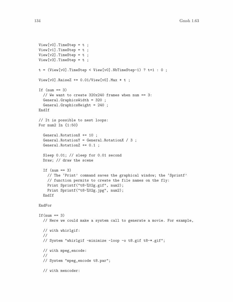
134 Gmsh 1.63
View[v0].TimeStep = t ;View[v1].TimeStep = t ;View[v2].TimeStep = t ;View[v3].TimeStep = t ;
t = (View[v0].TimeStep < View[v0].NbTimeStep-1) ? t+1 : 0 ;
View[v0].RaiseZ += 0.01/View[v0].Max * t ;
If (num == 3)// We want to create 320x240 frames when num == 3:General.GraphicsWidth = 320 ;General.GraphicsHeight = 240 ;
EndIf
// It is possible to nest loops:For num2 In {1:50}
General.RotationX += 10 ;General.RotationY = General.RotationX / 3 ;General.RotationZ += 0.1 ;
Sleep 0.01; // sleep for 0.01 secondDraw; // draw the scene
If (num == 3)// The ‘Print’ command saves the graphical window; the ‘Sprintf’// function permits to create the file names on the fly:Print Sprintf("t8-%02g.gif", num2);Print Sprintf("t8-%02g.jpg", num2);
EndIf
EndFor
If(num == 3)// Here we could make a system call to generate a movie. For example,
// with whirlgif://// System "whirlgif -minimize -loop -o t8.gif t8-*.gif";
// with mpeg_encode://// System "mpeg_encode t8.par";
// with mencoder:

Chapter 7: Tutorial 135
//// System "mencoder ’mf://*.jpg’ -mf fps=5 -o t8.mpg -ovc lavc// -lavcopts vcodec=mpeg1video:vhq";// System "mencoder ’mf://*.jpg’ -mf fps=5 -o t8.mpg -ovc lavc// -lavcopts vcodec=mpeg4:vhq";
// with ffmpeg://// System "ffmpeg -hq -r 5 -b 800 -vcodec mpeg1video// -i t8-%02d.jpg t8.mpg"// System "ffmpeg -hq -r 5 -b 800 -i t8-%02d.jpg t8.asf"
EndIf
EndFor
7.9 ‘t9.geo’
/*********************************************************************** Gmsh tutorial 9** Post-processing, plugins**********************************************************************/
// Plugins can be added to Gmsh in order to extend its// capabilities. For example, post-processing plugins can modify a// view, or create a new view based on previously loaded// views. Several default plugins are statically linked with Gmsh,// e.g. CutMap, CutPlane, CutSphere, Skin, Transform or Smooth.// Plugins can be controlled in the same way as other options: either// from the graphical interface (right click on the view button, then// ‘Plugins’), or from the command file.
// Let us for example include a three-dimensional scalar view:
Include "view3.pos" ;
// We then set some options for the ‘CutMap’ plugin (which extracts an// isovalue surface from a 3D scalar view), and run it:
Plugin(CutMap).A = 0.67 ; // iso-value levelPlugin(CutMap).iView = 0 ; // source view is View[0]Plugin(CutMap).Run ;
// We also set some options for the ‘CutPlane’ plugin (which computes

136 Gmsh 1.63
// a section of a 3D view), and then run it:
Plugin(CutPlane).A = 0 ;Plugin(CutPlane).B = 0.2 ;Plugin(CutPlane).C = 1 ;Plugin(CutPlane).D = 0 ;Plugin(CutPlane).Run ;
// Add a title
Plugin(Annotate).Text = "A nice title" ;// By convention, a value greater than 99999 represents the center (we// could also use ‘General.GraphicsWidth/2’, but that would only center// the string for the current window size):Plugin(Annotate).X = 1.e5;Plugin(Annotate).Y = 50 ;Plugin(Annotate).Font = "Times-BoldItalic" ;Plugin(Annotate).FontSize = 28 ;Plugin(Annotate).Align = "Center" ;Plugin(Annotate).Run ;
Plugin(Annotate).Text = "(and a small subtitle)" ;Plugin(Annotate).Y = 70 ;Plugin(Annotate).Font = "Times-Roman" ;Plugin(Annotate).FontSize = 12 ;Plugin(Annotate).Run ;
// We finish by setting some options and redrawing the scene:
General.BackgroundGradient = 1;
View[0].Light = 1;View[0].IntervalsType = 1;View[0].NbIso = 6;View[0].SmoothNormals = 1;
View[1].IntervalsType = 2;
View[2].IntervalsType = 2;
Draw;

Chapter 8: Running Gmsh 137
8 Running Gmsh
8.1 Interactive mode
Gmsh’s first operating mode is the ‘interactive graphical mode’. To launch Gmsh in inter-active mode, just click or double-click on the Gmsh icon (Windows and Mac), or type
> gmsh
at your shell prompt in a terminal (Unix). This will open two windows: the graphicwindow (with a status bar at the bottom) and the menu window (with a menu bar andsome context-dependent buttons).To open the first tutorial file (see Chapter 7 [Tutorial], page 113), select the ‘File->Open’menu, and choose ‘t1.geo’ in the input field. When using a terminal, you can also specifythe file name directly on the command line, i.e.:
> gmsh t1.geo
To perform the mesh generation, go to the mesh module (by selecting ‘Mesh’ in the modulemenu) and choose the required dimension in the context-dependent buttons (‘1D’ will meshall the lines; ‘2D’ will mesh all the surfaces—as well as all the lines if ‘1D’ was not calledbefore; ‘3D’ will mesh all the volumes—and all the surfaces if ‘2D’ was not called before). Tosave the resulting mesh in the current mesh format, choose ‘Save’ in the context-dependentbuttons, or select the appropriate format with the ‘File->Save As’ menu. The default meshfile name is based on the name of the first input file on the command line (or ‘untitled’if there wasn’t any input file given), with an appended extension depending on the meshformat1.To create a new geometry or to modify an existing geometry, select ’Geometry’ in themodule menu, and follow the context-dependent buttons. For example, to create a spline,select ‘Elementary’, ‘Add’, ‘New’ and ‘Spline’. You will then be asked to select a list ofpoints, and to type e to finish the selection (or q to abort it). Once the interactive commandis completed, a text string is automatically added at the end of the current project file. Youcan edit this project file by hand at any time by pressing the ‘Edit’ button in the ‘Geometry’menu and then reloading the project by pressing ‘Reload’. For example, it is often fasterto define variables and points directly in the project file, and then use the graphical userinterface to define the lines, the surfaces and the volumes interactively.Several files can be loaded simultaneously in Gmsh. The first one defines the project, whilethe others are appended (‘merged’) to this project. You can merge such files with the‘File->Merge’ menu, or by directly specifying the names of the files on the command line.For example, to merge the post-processing views contained in the files ‘view1.pos’ and‘view2.pos’ together with the geometry of the first tutorial ‘t1.geo’, you can type thefollowing command:
> gmsh t1.geo view1.pos view2.pos
In the Post-Processing module (select ‘Post-Processing’ in the module menu), two viewbuttons will appear, respectively labeled ‘a scalar map’ and ‘a vector map’. A mouse click
1 Nearly all the interactive commands have shortcuts: see Section 8.5 [Keyboard shortcuts], page 141, or select‘Help->Keyboard Shortcuts’ in the menu.

138 Gmsh 1.63
on the name will toggle the visibility of the selected view, while a click on the arrow buttonon the right will provide access to the view’s options. If you want the modifications madeto one view to affect also all the other views, select the ‘Apply next changes to all views’or ‘Force same options for all views’ option in the ‘Tools->Options->Post-processing’ menu.Note that all the options specified interactively can also be directly specified in the ASCIIinput files. All available options, with their current values, can be saved into a file byselecting ‘File->Save As->Gmsh options’, or simply viewed by pressing the ‘?’ button inthe status bar. To save the current options as your default preferences for all future Gmshsessions, use the ‘Tools->Options->Save’ button.
8.2 Non-interactive mode
Gmsh’s second operating mode is the non-interactive (or ‘batch’) mode. In this mode, thereis no graphical user interface, and all operations are performed without any user interaction2. For example, to mesh the first tutorial in non-interactive mode, just type:
> gmsh t1.geo -2
To mesh the same example, but with the background mesh available in the file ‘bgmesh.pos’,type:
> gmsh t1.geo -2 -bgm bgmesh.pos
For the list of all command-line options, see Section 8.3 [Command-line options], page 138.
8.3 Command-line options
Geometry options:
-0 Parse input files, output unrolled geometry, and exit
Mesh options:
-1, -2, -3Perform batch 1D, 2D and 3D mesh generation
-saveall Save all elements (discard physical group definitions)
-o file Specify mesh output file name
-format stringSet output mesh format (msh, unv, gref, stl, p3d)
-algo stringSelect mesh algorithm (iso, tri, aniso, netgen)
-smooth intSet number of mesh smoothing steps
-optimizeOptimize quality of tetrahedral elements
2 If you compile Gmsh without the graphical user interface, i.e., with ./configure --disable-gui, this is theonly mode you have access to.

Chapter 8: Running Gmsh 139
-order intSet the order of the generated elements (1, 2)
-scale floatSet global scaling factor
-meshscale floatSet mesh scaling factor
-clscale floatSet characteristic length scaling factor
-rand floatSet random perturbation factor
-bgm file Load background mesh from file
-constrainConstrain background mesh with characteristic lengths
-histogramPrint mesh quality histogram
-extrude Use old extrusion mesh generator
-recombineRecombine meshes from old extrusion mesh generator
-interactiveDisplay 2D mesh construction interactively
Post-processing options:
-noview Hide all views on startup
-link int Select link mode between views (0, 1, 2, 3, 4)
-smoothviewSmooth views
-combine Combine views having identical names into multi-time-step views
Display options:
-nodb Disable double buffering
-fontsize intSpecify the font size for the GUI
-scheme stringSpecify FLTK GUI scheme
-display stringSpecify display
Other options:

140 Gmsh 1.63
-a, -g, -m, -s, -pStart in automatic, geometry, mesh, solver or post-processing mode
-pid Print pid on stdout
-listen Always listen to external solver requests
-v int Set verbosity level
-nopopup Don’t popup dialog windows in scripts
-string "string"Parse option string at startup
-option fileParse option file at startup
-convert file filePerform batch conversion of views and meshes into latest file formats
-version Show version number
-info Show detailed version information
-help Show this message
8.4 Mouse actions
In the following, for a 2 button mouse, Middle button = Shift+Left button. For a 1 buttonmouse, Middle button = Shift+Left button and Right button = Alt+Left button.Move the mouse:• Highlight the elementary geometrical entity currently under the mouse pointer and
display its properties in the status bar• Resize a lasso zoom or a lasso selection started with Ctrl+Left button
Left button:• Rotate• Select an entity• Accept a lasso zoom or a lasso selection started with Ctrl+Left button
Ctrl+Left button: Start a lasso zoom or a lasso selectionMiddle button:• Zoom• Unselect an entity• Cancel a lasso zoom or a lasso selection
Ctrl+Middle button: Orthogonalize displayRight button:• Pan• Cancel a lasso zoom or a lasso selection• Pop-up menu on post-processing view button
Ctrl+Right button: Reset to default viewpoint

Chapter 8: Running Gmsh 141
8.5 Keyboard shortcuts
(On Mac Ctrl is replaced by Cmd (the ‘Apple key’) in the shortcuts below.)
Left arrow Go to previous time step
Right arrowGo to next time step
Up arrow Make previous view visible
Down arrowMake next view visible
< Go back to previous context
> Go forward to next context
0 Reload project file
1 or F1 Mesh lines
2 or F2 Mesh surfaces
3 or F3 Mesh volumes
Escape Cancel lasso zoom/selection, toggle mouse selection ON/OFF
g Go to geometry module
m Go to mesh module
p Go to post-processing module
s Go to solver module
Shift+a Bring all windows to front
Shift+g Show geometry options
Shift+m Show mesh options
Shift+o Show general options
Shift+p Show post-processing options
Shift+s Show solver options
Shift+w Show post-processing view options
Ctrl+i Show statistics window
Ctrl+l Show message console
Ctrl+n Create new project file
Ctrl+o Open project file
Ctrl+q Quit

142 Gmsh 1.63
Ctrl+r Rename project file
Ctrl+s Save file
Shift+Ctrl+cShow clipping plane window
Shift+Ctrl+mShow manipulator window
Shift+Ctrl+nShow option window
Shift+Ctrl+oMerge file(s)
Shift+Ctrl+sSave mesh in default format
Shift+Ctrl+vShow visibility window
Alt+a Loop through axes modes
Alt+b Hide/show bounding boxes
Alt+c Loop through predefined color schemes
Alt+d Change surface mesh display mode (solid/wireframe)
Alt+f Change redraw mode (fast/full)
Alt+g Loop through grid modes for visible post-processing views
Alt+h Hide/show all post-processing views
Alt+i Hide/show all post-processing view scales
Alt+l Hide/show geometry lines
Alt+m Toggle visibility of all mesh entities
Alt+n Hide/show all post-processing view annotations
Alt+o Change projection mode (orthographic/perspective)
Alt+p Hide/show geometry points
Alt+s Hide/show geometry surfaces
Alt+t Loop through interval modes for visible post-processing views
Alt+v Hide/show geometry volumes
Alt+w Enable/disable all lighting
Alt+x Set X view
Alt+y Set Y view

Chapter 8: Running Gmsh 143
Alt+z Set Z view
Alt+Shift+aHide/show small axes
Alt+Shift+lHide/show surface mesh edges
Alt+Shift+oAdjust projection parameters
Alt+Shift+pHide/show mesh points
Alt+Shift+sHide/show mesh surfaces
Alt+Shift+vHide/show mesh volumes
Alt+Shift+xSet -X view
Alt+Shift+ySet -Y view
Alt+Shift+zSet -Z view

144 Gmsh 1.63

Chapter 9: File formats 145
9 File formats
This chapter describes Gmsh’s native mesh and post-processing file formats. (These formatshave version numbers that are independent of Gmsh’s main version number.)All non-parsed file formats have sections enclosed between $Key and $EndKey tags.
9.1 Gmsh mesh file formats
Please note that the list of nodes and elements in Gmsh’s mesh files do not have to be denseor ordered (i.e., the node and element numbers do not have to be given in a consecutiveor even an ordered way). A sample C++ program to transform the formats so that all listsare dense and ordered is available in the source distribution (‘utils/misc/mshsort.cpp’).This program is also a good example on how to read and write files in the ‘.msh’ format.
9.1.1 Version 1.0
The ‘.msh’ file format, version 1.0, is Gmsh’s old native mesh file format, now supersededby the format described in Section 9.1.2 [Version 2.0], page 147.In the ‘.msh’ file format, version 1.0, the file is divided in two sections, defining the nodes($NOD-$ENDNOD) and the elements ($ELM-$ENDELM) in the mesh:
$NODnumber-of-nodesnode-number x-coord y-coord z-coord...$ENDNOD$ELMnumber-of-elementselm-number elm-type reg-phys reg-elem number-of-nodes node-number-list...$ENDELM
where
number-of-nodesis the number of nodes in the mesh.
node-numberis the number (index) of the n-th node in the mesh. Note that the node-numbersdo not have to be given in a consecutive (or even an ordered) way.
x-coord y-coord z-coordare the floating point values giving the X, Y and Z coordinates of the n-th node.
number-of-elementsis the number of elements in the mesh.
elm-numberis the number (index) of the n-th element in the mesh. Note that theelm-numbers do not have to be given in a consecutive (or even an ordered)way.
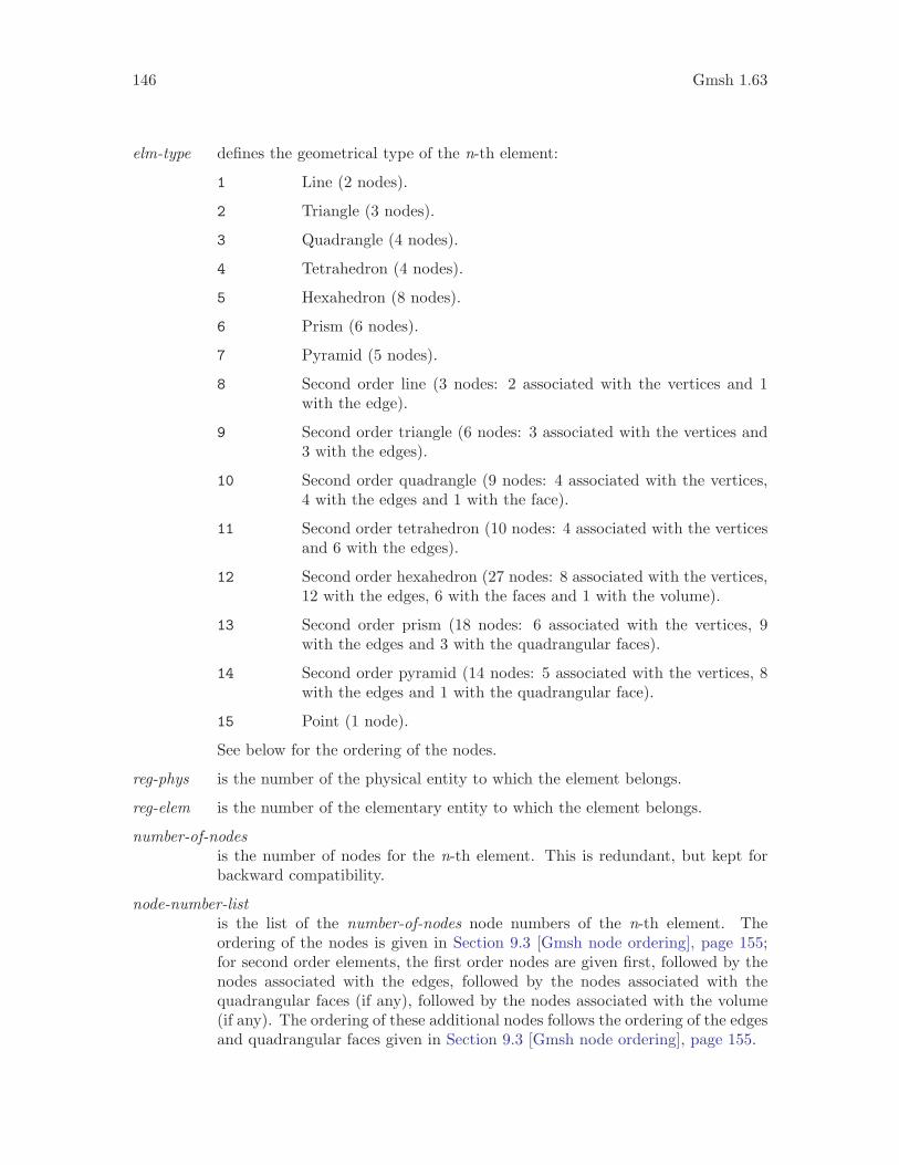
146 Gmsh 1.63
elm-type defines the geometrical type of the n-th element:
1 Line (2 nodes).
2 Triangle (3 nodes).
3 Quadrangle (4 nodes).
4 Tetrahedron (4 nodes).
5 Hexahedron (8 nodes).
6 Prism (6 nodes).
7 Pyramid (5 nodes).
8 Second order line (3 nodes: 2 associated with the vertices and 1with the edge).
9 Second order triangle (6 nodes: 3 associated with the vertices and3 with the edges).
10 Second order quadrangle (9 nodes: 4 associated with the vertices,4 with the edges and 1 with the face).
11 Second order tetrahedron (10 nodes: 4 associated with the verticesand 6 with the edges).
12 Second order hexahedron (27 nodes: 8 associated with the vertices,12 with the edges, 6 with the faces and 1 with the volume).
13 Second order prism (18 nodes: 6 associated with the vertices, 9with the edges and 3 with the quadrangular faces).
14 Second order pyramid (14 nodes: 5 associated with the vertices, 8with the edges and 1 with the quadrangular face).
15 Point (1 node).
See below for the ordering of the nodes.
reg-phys is the number of the physical entity to which the element belongs.
reg-elem is the number of the elementary entity to which the element belongs.
number-of-nodesis the number of nodes for the n-th element. This is redundant, but kept forbackward compatibility.
node-number-listis the list of the number-of-nodes node numbers of the n-th element. Theordering of the nodes is given in Section 9.3 [Gmsh node ordering], page 155;for second order elements, the first order nodes are given first, followed by thenodes associated with the edges, followed by the nodes associated with thequadrangular faces (if any), followed by the nodes associated with the volume(if any). The ordering of these additional nodes follows the ordering of the edgesand quadrangular faces given in Section 9.3 [Gmsh node ordering], page 155.

Chapter 9: File formats 147
9.1.2 Version 2.0
Version 2.0 of the ‘.msh’ file format is Gmsh’s new native mesh file format. It is very similarto the old one (see Section 9.1.1 [Version 1.0], page 145), but is more general: it containsinformation about itself and allows to associate an arbitrary number of integer tags witheach element.The ‘.msh’ file format, version 2.0, is divided in three sections, defining the file format($MeshFormat-$EndMeshFormat), the nodes ($Nodes-$EndNodes) and the elements($Elements-$EndElements) in the mesh:
$MeshFormat2.0 file-type data-size$EndMeshFormat$Nodesnumber-of-nodesnode-number x-coord y-coord z-coord...$EndNodes$Elementsnumber-of-elementselm-number elm-type number-of-tags < tag > ... node-number-list...$EndElements
where
file-type is an integer equal to 0 in the ASCII file format.
data-size is an integer equal to the size of the floating point numbers used in the file(usually, data-size = sizeof(double)).
number-of-nodesis the number of nodes in the mesh.
node-numberis the number (index) of the n-th node in the mesh. Note that the node-numbersdo not have to be given in a consecutive (or even an ordered) way.
x-coord y-coord z-coordare the floating point values giving the X, Y and Z coordinates of the n-th node.
number-of-elementsis the number of elements in the mesh.
elm-numberis the number (index) of the n-th element in the mesh. Note that theelm-numbers do not have to be given in a consecutive (or even an ordered)way.
elm-type defines the geometrical type of the n-th element:
1 Line (2 nodes).
2 Triangle (3 nodes).

148 Gmsh 1.63
3 Quadrangle (4 nodes).
4 Tetrahedron (4 nodes).
5 Hexahedron (8 nodes).
6 Prism (6 nodes).
7 Pyramid (5 nodes).
8 Second order line (3 nodes: 2 associated with the vertices and 1with the edge).
9 Second order triangle (6 nodes: 3 associated with the vertices and3 with the edges).
10 Second order quadrangle (9 nodes: 4 associated with the vertices,4 with the edges and 1 with the face).
11 Second order tetrahedron (10 nodes: 4 associated with the verticesand 6 with the edges).
12 Second order hexahedron (27 nodes: 8 associated with the vertices,12 with the edges, 6 with the faces and 1 with the volume).
13 Second order prism (18 nodes: 6 associated with the vertices, 9with the edges and 3 with the quadrangular faces).
14 Second order pyramid (14 nodes: 5 associated with the vertices, 8with the edges and 1 with the quadrangular face).
15 Point (1 node).
See below for the ordering of the nodes.
number-of-tagsgives the number of tags for the n-th element. By default, Gmsh generatesmeshes with two tags and reads files with an arbitrary number of tags: seebelow.
tag is an integer tag associated with the n-th element. By default, the first tag isthe number of the physical entity to which the element belongs; the second isthe number of the elementary geometrical entity to which the element belongs;the third is the number of a mesh partition to which the element belongs.
node-number-listis the list of the node numbers of the n-th element. The ordering of the nodes isgiven in Section 9.3 [Gmsh node ordering], page 155; for second order elements,the first order nodes are given first, followed by the nodes associated with theedges, followed by the nodes associated with the quadrangular faces (if any),followed by the nodes associated with the volume (if any). The ordering ofthese additional nodes follows the ordering of the edges and quadrangular facesgiven in Section 9.3 [Gmsh node ordering], page 155.

Chapter 9: File formats 149
9.2 Gmsh post-processing file formats
Gmsh can read and write data sets in three different file formats: the “parsed”, “ASCII”and “binary” file formats. The parsed format is the oldest and most flexible, but also theslowest to read/write. The ASCII and binary formats are less flexible but allow for fasterread/write operations, which is useful for (very) large data sets.Gmsh can convert any format to any other, either in a script (cf. Save View andPostProcessing.Format in Section 6.1 [Post-processing commands], page 83, andSection 6.3 [Post-processing options], page 96, respectively) or in the graphical userinterface (using the ‘View->Save As’ menu).
9.2.1 Parsed post-processing file format
Gmsh’s oldest post-processing format (“parsed”) is read by Gmsh’s script parser (see alsoSection 6.1 [Post-processing commands], page 83). You can thus, for example, embedparsed post-processing views directly into your geometrical descriptions (see, e.g., Sec-tion 7.4 [t4.geo], page 119).The parsed format is very powerful, since all the values are expressions, and it can be easilygenerated “on-the-fly”, as there is no header containing a priori information on the size ofthe data set. Its syntax is also very permissive, which makes it ideal for testing purposes. Itsmain disadvantage resides in the overhead introduced by the parser, which makes loading aview in parsed format slower than loading a view in ASCII or binary format. This is onlya disadvantage for very large data sets, though.A post-processing view in parsed format is defined as follows (there can be one or moreviews in the same file):
View "string" {< TIME { expression-list }; >type ( list-of-coords ) { list-of-values };...
};
where the 47 object types that can be displayed are:type #list-of-coords #list-of-values
--------------------------------------------------------------------Scalar point SP 3 1 * nb-time-stepsVector point VP 3 3 * nb-time-stepsTensor point TP 3 9 * nb-time-stepsScalar line SL 6 2 * nb-time-stepsVector line VL 6 6 * nb-time-stepsTensor line TL 6 18 * nb-time-stepsScalar triangle ST 9 3 * nb-time-stepsVector triangle VT 9 9 * nb-time-stepsTensor triangle TT 9 27 * nb-time-stepsScalar quadrangle SQ 12 4 * nb-time-stepsVector quadrangle VQ 12 12 * nb-time-stepsTensor quadrangle TQ 12 36 * nb-time-steps
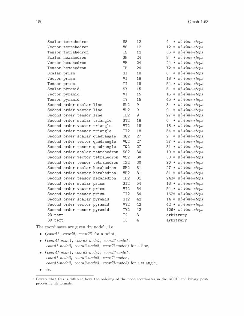
150 Gmsh 1.63
Scalar tetrahedron SS 12 4 * nb-time-stepsVector tetrahedron VS 12 12 * nb-time-stepsTensor tetrahedron TS 12 36 * nb-time-stepsScalar hexahedron SH 24 8 * nb-time-stepsVector hexahedron VH 24 24 * nb-time-stepsTensor hexahedron TH 24 72 * nb-time-stepsScalar prism SI 18 6 * nb-time-stepsVector prism VI 18 18 * nb-time-stepsTensor prism TI 18 54 * nb-time-stepsScalar pyramid SY 15 5 * nb-time-stepsVector pyramid VY 15 15 * nb-time-stepsTensor pyramid TY 15 45 * nb-time-stepsSecond order scalar line SL2 9 3 * nb-time-stepsSecond order vector line VL2 9 9 * nb-time-stepsSecond order tensor line TL2 9 27 * nb-time-stepsSecond order scalar triangle ST2 18 6 * nb-time-stepsSecond order vector triangle VT2 18 18 * nb-time-stepsSecond order tensor triangle TT2 18 54 * nb-time-stepsSecond order scalar quadrangle SQ2 27 9 * nb-time-stepsSecond order vector quadrangle VQ2 27 27 * nb-time-stepsSecond order tensor quadrangle TQ2 27 81 * nb-time-stepsSecond order scalar tetrahedron SS2 30 10 * nb-time-stepsSecond order vector tetrahedron VS2 30 30 * nb-time-stepsSecond order tensor tetrahedron TS2 30 90 * nb-time-stepsSecond order scalar hexahedron SH2 81 27 * nb-time-stepsSecond order vector hexahedron VH2 81 81 * nb-time-stepsSecond order tensor hexahedron TH2 81 243* nb-time-stepsSecond order scalar prism SI2 54 18 * nb-time-stepsSecond order vector prism VI2 54 54 * nb-time-stepsSecond order tensor prism TI2 54 162* nb-time-stepsSecond order scalar pyramid SY2 42 14 * nb-time-stepsSecond order vector pyramid VY2 42 42 * nb-time-stepsSecond order tensor pyramid TY2 42 126* nb-time-steps2D text T2 3 arbitrary3D text T3 4 arbitrary
The coordinates are given ‘by node’1, i.e.,
• (coord1, coord2, coord3) for a point,
• (coord1-node1, coord2-node1, coord3-node1,coord1-node2, coord2-node2, coord3-node2) for a line,
• (coord1-node1, coord2-node1, coord3-node1,coord1-node2, coord2-node2, coord3-node2,coord1-node3, coord2-node3, coord3-node3) for a triangle,
• etc.
1 Beware that this is different from the ordering of the node coordinates in the ASCII and binary post-processing file formats.

Chapter 9: File formats 151
The ordering of the nodes is given in Section 9.3 [Gmsh node ordering], page 155. For secondorder elements, the first order nodes are given first, followed by the nodes associated withthe edges, followed by the nodes associated with the quadrangular faces (if any), followedby the nodes associated with the volume (if any). The ordering of these additional nodesfollows the ordering of the edges and quadrangular faces given in Section 9.3 [Gmsh nodeordering], page 155.The values are given by time step, by node and by component, i.e.:
comp1-node1-time1, comp2-node1-time1, comp3-node1-time1,comp1-node2-time1, comp2-node2-time1, comp3-node2-time1,comp1-node3-time1, comp2-node3-time1, comp3-node3-time1,comp1-node1-time2, comp2-node1-time2, comp3-node1-time2,comp1-node2-time2, comp2-node2-time2, comp3-node2-time2,comp1-node3-time2, comp2-node3-time2, comp3-node3-time2,...
For the 2D text objects, the two first expressions in list-of-coords give the X-Y position ofthe string in screen coordinates, measured from the top-left corner of the window. If thefirst (respectively second) expression is negative, the position is measured from the right(respectively bottom) edge of the window. If the value of the first (respectively second)expression is larger than 99999, the string is centered horizontally (respectively vertically).If the third expression is equal to zero, the text is aligned bottom-left and displayed usingthe default font and size. Otherwise, the third expression is converted into an integerwhose eight lower bits give the font size, whose eight next bits select the font (the indexcorresponds to the position in the font menu in the GUI), and whose eight next bits definethe text alignment (0=bottom-left, 1=bottom-center, 2=bottom-right, 3=top-left, 4=top-center, 5=top-right, 6=center-left, 7=center-center, 8=center-right).For the 3D text objects, the three first expressions in list-of-coords give the XYZ position ofthe string in model (real world) coordinates. The fourth expression has the same meaningas the third expression in 2D text objects.For both 2D and 3D text objects, the list-of-values can contain an arbitrary number ofchar-expressions.The optional TIME list can contain a list of expressions giving the value of the time (or anyother variable) for which an evolution was saved.
9.2.2 ASCII post-processing file format
The ASCII post-processing file is divided in several sections: one format section, enclosedbetween $PostFormat-$EndPostFormat tags, and one or more post-processing views, en-closed between $View-$EndView tags:
$PostFormat1.4 file-type data-size$EndPostFormat$Viewview-name nb-time-stepsnb-scalar-points nb-vector-points nb-tensor-pointsnb-scalar-lines nb-vector-lines nb-tensor-lines

152 Gmsh 1.63
nb-scalar-triangles nb-vector-triangles nb-tensor-trianglesnb-scalar-quadrangles nb-vector-quadrangles nb-tensor-quadranglesnb-scalar-tetrahedra nb-vector-tetrahedra nb-tensor-tetrahedranb-scalar-hexahedra nb-vector-hexahedra nb-tensor-hexahedranb-scalar-prisms nb-vector-prisms nb-tensor-prismsnb-scalar-pyramids nb-vector-pyramids nb-tensor-pyramidsnb-scalar-lines2 nb-vector-lines2 nb-tensor-lines2nb-scalar-triangles2 nb-vector-triangles2 nb-tensor-triangles2nb-scalar-quadrangles2 nb-vector-quadrangles2 nb-tensor-quadrangles2nb-scalar-tetrahedra2 nb-vector-tetrahedra2 nb-tensor-tetrahedra2nb-scalar-hexahedra2 nb-vector-hexahedra2 nb-tensor-hexahedra2nb-scalar-prisms2 nb-vector-prisms2 nb-tensor-prisms2nb-scalar-pyramids2 nb-vector-pyramids2 nb-tensor-pyramids2nb-text2d nb-text2d-chars nb-text3d nb-text3d-charstime-step-values< scalar-point-value > ... < vector-point-value > ...
< tensor-point-value > ...< scalar-line-value > ... < vector-line-value > ...
< tensor-line-value > ...< scalar-triangle-value > ... < vector-triangle-value > ...
< tensor-triangle-value > ...< scalar-quadrangle-value > ... < vector-quadrangle-value > ...
< tensor-quadrangle-value > ...< scalar-tetrahedron-value > ... < vector-tetrahedron-value > ...
< tensor-tetrahedron-value > ...< scalar-hexahedron-value > ... < vector-hexahedron-value > ...
< tensor-hexahedron-value > ...< scalar-prism-value > ... < vector-prism-value > ...
< tensor-prism-value > ...< scalar-pyramid-value > ... < vector-pyramid-value > ...
< tensor-pyramid-value > ...< scalar-line2-value > ... < vector-line2-value > ...
< tensor-line2-value > ...< scalar-triangle2-value > ... < vector-triangle2-value > ...
< tensor-triangle2-value > ...< scalar-quadrangle2-value > ... < vector-quadrangle2-value > ...
< tensor-quadrangle2-value > ...< scalar-tetrahedron2-value > ... < vector-tetrahedron2-value > ...
< tensor-tetrahedron2-value > ...< scalar-hexahedron2-value > ... < vector-hexahedron2-value > ...
< tensor-hexahedron2-value > ...< scalar-prism2-value > ... < vector-prism2-value > ...
< tensor-prism2-value > ...< scalar-pyramid2-value > ... < vector-pyramid2-value > ...
< tensor-pyramid2-value > ...< text2d > ... < text2d-chars > ...< text3d > ... < text3d-chars > ...

Chapter 9: File formats 153
$EndView
where
file-type is an integer equal to 0 in the ASCII file format.
data-size is an integer equal to the size of the floating point numbers used in the file(usually, data-size = sizeof(double)).
view-name is a string containing the name of the view (max. 256 characters).
nb-time-stepsis an integer giving the number of time steps in the view.
nb-scalar-pointsnb-vector-points... are integers giving the number of scalar points, vector points, . . . , in the view.
nb-text2d
nb-text3d are integers giving the number of 2D and 3D text strings in the view.
nb-text2d-charsnb-text3d-chars
are integers giving the total number of characters in the 2D and 3D strings.
time-step-valuesis a list of nb-time-steps double precision numbers giving the value of the time(or any other variable) for which an evolution was saved.
scalar-point-valuevector-point-value... are lists of double precision numbers giving the node coordinates and the values
associated with the nodes of the nb-scalar-points scalar points, nb-vector-pointsvector points, . . . , for each of the time-step-values.For example, vector-triangle-value is defined as:
coord1-node1 coord1-node2 coord1-node3coord2-node1 coord2-node2 coord2-node3coord3-node1 coord3-node2 coord3-node3comp1-node1-time1 comp2-node1-time1 comp3-node1-time1comp1-node2-time1 comp2-node2-time1 comp3-node2-time1comp1-node3-time1 comp2-node3-time1 comp3-node3-time1comp1-node1-time2 comp2-node1-time2 comp3-node1-time2comp1-node2-time2 comp2-node2-time2 comp3-node2-time2comp1-node3-time2 comp2-node3-time2 comp3-node3-time2...
The ordering of the nodes is given in Section 9.3 [Gmsh node ordering], page 155.For second order elements, the first order nodes are given first, followed by thenodes associated with the edges, followed by the nodes associated with thequadrangular faces (if any), followed by the nodes associated with the volume(if any). The ordering of these additional nodes follows the ordering of the edgesand quadrangular faces given in Section 9.3 [Gmsh node ordering], page 155.

154 Gmsh 1.63
text2d is a list of 4 double precision numbers:coord1 coord2 style index
where coord1 and coord2 give the X-Y position of the 2D string in screen co-ordinates (measured from the top-left corner of the window) and where indexgives the starting index of the string in text2d-chars. If coord1 (respectivelycoord2) is negative, the position is measured from the right (respectively bot-tom) edge of the window. If coord1 (respectively coord2) is larger than 99999,the string is centered horizontally (respectively vertically). If style is equal tozero, the text is aligned bottom-left and displayed using the default font andsize. Otherwise, style is converted into an integer whose eight lower bits givethe font size, whose eight next bits select the font (the index corresponds tothe position in the font menu in the GUI), and whose eight next bits define thetext alignment (0=bottom-left, 1=bottom-center, 2=bottom-right, 3=top-left,4=top-center, 5=top-right, 6=center-left, 7=center-center, 8=center-right).
text2d-charsis a list of nb-text2d-chars characters. Substrings are separated with the null‘\0’ character.
text3d is a list of 5 double precision numberscoord1 coord2 coord3 style index
where coord1, coord2 and coord3 give the XYZ coordinates of the string inmodel (real world) coordinates, index gives the starting index of the string intext3d-chars, and style has the same meaning as in text2d.
text3d-charsis a list of nb-text3d-chars chars. Substrings are separated with the null ‘\0’character.
9.2.3 Binary post-processing file format
The binary post-processing file format is the same as the ASCII file format described inSection 9.2.2 [ASCII post-processing file format], page 151, except that:1. file-type equals 1.2. all lists of floating point numbers and characters are written in binary format3. there is an additional integer, of value 1, written before time-step-values. This integer
is used for detecting if the computer on which the binary file was written and thecomputer on which the file is read are of the same type (little or big endian).
Here is a pseudo C code to write a post-processing file in binary format:int one = 1;
fprintf(file, "$PostFormat\n");fprintf(file, "%g %d %d\n", 1.4, 1, sizeof(double));fprintf(file, "$EndPostFormat\n");fprintf(file, "$View\n");fprintf(file, "%s %d "

Chapter 9: File formats 155
"%d %d %d %d %d %d %d %d %d ""%d %d %d %d %d %d %d %d %d ""%d %d %d %d %d %d %d %d %d ""%d %d %d %d %d %d %d %d %d ""%d %d %d %d %d %d %d %d %d ""%d %d %d %d\n",view-name, nb-time-steps,nb-scalar-points, nb-vector-points, nb-tensor-points,nb-scalar-lines, nb-vector-lines, nb-tensor-lines,nb-scalar-triangles, nb-vector-triangles, nb-tensor-triangles,nb-scalar-quadrangles, nb-vector-quadrangles, nb-tensor-quadrangles,nb-scalar-tetrahedra, nb-vector-tetrahedra, nb-tensor-tetrahedra,nb-scalar-hexahedra, nb-vector-hexahedra, nb-tensor-hexahedra,nb-scalar-prisms, nb-vector-prisms, nb-tensor-prisms,nb-scalar-pyramids, nb-vector-pyramids, nb-tensor-pyramids,nb-scalar-lines2, nb-vector-lines2, nb-tensor-lines2,nb-scalar-triangles2, nb-vector-triangles2, nb-tensor-triangles2,nb-scalar-quadrangles2, nb-vector-quadrangles2, nb-tensor-quadrangles2,nb-scalar-tetrahedra2, nb-vector-tetrahedra2, nb-tensor-tetrahedra2,nb-scalar-hexahedra2, nb-vector-hexahedra2, nb-tensor-hexahedra2,nb-scalar-prisms2, nb-vector-prisms2, nb-tensor-prisms2,nb-scalar-pyramids2, nb-vector-pyramids2, nb-tensor-pyramids2,nb-text2d, nb-text2d-chars, nb-text3d, nb-text3d-chars);
fwrite(&one, sizeof(int), 1, file);fwrite(time-step-values, sizeof(double), nb-time-steps, file);fwrite(all-scalar-point-values, sizeof(double), ..., file);...fprintf(file, "\n$EndView\n");
In this pseudo-code, all-scalar-point-values is the array of double precision numbers con-taining all the scalar-point-value lists, put one after each other in order to form a long arrayof doubles. The principle is the same for all other kinds of values.
9.3 Gmsh node ordering
For all mesh and post-processing file formats, the reference elements are defined as follows:
Point:v||
-----1-----u||

156 Gmsh 1.63
Line:edge 1: nodes 1 2
v||
--1-----2--u||
Triangle:edge 1: nodes 1 2
v 2: 2 3| 3: 3 1|3|\| \|__\___u1 2
Quadrangle:edge 1: nodes 1 2 quad. face 1: nodes 1 2 3 4
v 2: 2 3| 3: 3 4
4--|--3 4: 4 1| | |
-----------u| | |1--|--2
|
Tetrahedron:edge 1: nodes 1 2
v 2: 2 3| 3: 3 1| 4: 4 1| 5: 4 33 6: 4 2|\| \|__\2_____u1\ /\4\w

Chapter 9: File formats 157
Hexahedron:edge 1: nodes 1 2 quad. face 1: nodes 1 2 3 4
v 2: 1 4 2: 1 2 5 6| 3: 1 5 3: 1 4 5 8| 4: 2 3 4: 2 3 6 7
4----|--3 5: 2 6 5: 3 4 7 8|\ | |\ 6: 3 4 6: 5 6 7 8| 8-------7 7: 3 7| | ----|---u 8: 4 81-|---\-2 | 9: 5 6\| \ \| 10: 5 85-----\-6 11: 6 7
\ 12: 7 8w
Prism:edge 1: nodes 1 2 quad. face 1: nodes 1 2 4 5
v 2: 1 3 2: 1 3 4 63 | 3: 1 4 3: 2 3 5 6|\| 4: 2 3| | 5: 2 51_|2 6: 3 6\| 6 7: 4 5|_|_\___u 8: 4 6\| \ 9: 5 64 __5\\w
Pyramid:edge 1: nodes 1 2 quad. face 1: nodes 1 2 3 4
v 2 1 4| 3 1 5| 4 2 3
4---|---3 5 2 5| \ | /| 6 3 4| \ -/-|---u 7 3 5| / 5\ | 8 4 51/----\-2
\\w

158 Gmsh 1.63
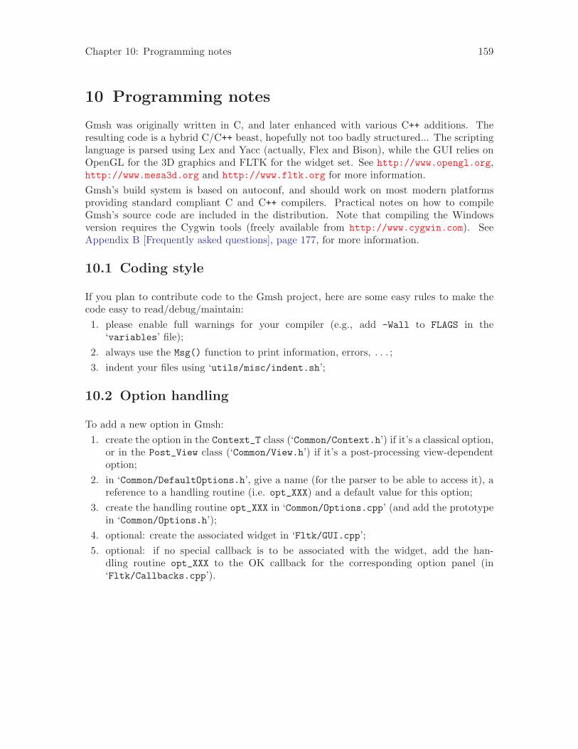
Chapter 10: Programming notes 159
10 Programming notes
Gmsh was originally written in C, and later enhanced with various C++ additions. Theresulting code is a hybrid C/C++ beast, hopefully not too badly structured... The scriptinglanguage is parsed using Lex and Yacc (actually, Flex and Bison), while the GUI relies onOpenGL for the 3D graphics and FLTK for the widget set. See http://www.opengl.org,http://www.mesa3d.org and http://www.fltk.org for more information.Gmsh’s build system is based on autoconf, and should work on most modern platformsproviding standard compliant C and C++ compilers. Practical notes on how to compileGmsh’s source code are included in the distribution. Note that compiling the Windowsversion requires the Cygwin tools (freely available from http://www.cygwin.com). SeeAppendix B [Frequently asked questions], page 177, for more information.
10.1 Coding style
If you plan to contribute code to the Gmsh project, here are some easy rules to make thecode easy to read/debug/maintain:1. please enable full warnings for your compiler (e.g., add -Wall to FLAGS in the
‘variables’ file);2. always use the Msg() function to print information, errors, . . . ;3. indent your files using ‘utils/misc/indent.sh’;
10.2 Option handling
To add a new option in Gmsh:1. create the option in the Context_T class (‘Common/Context.h’) if it’s a classical option,
or in the Post_View class (‘Common/View.h’) if it’s a post-processing view-dependentoption;
2. in ‘Common/DefaultOptions.h’, give a name (for the parser to be able to access it), areference to a handling routine (i.e. opt_XXX) and a default value for this option;
3. create the handling routine opt_XXX in ‘Common/Options.cpp’ (and add the prototypein ‘Common/Options.h’);
4. optional: create the associated widget in ‘Fltk/GUI.cpp’;5. optional: if no special callback is to be associated with the widget, add the han-
dling routine opt_XXX to the OK callback for the corresponding option panel (in‘Fltk/Callbacks.cpp’).

160 Gmsh 1.63

Chapter 11: Bugs, versions and credits 161
11 Bugs, versions and credits
11.1 Bugs
If you think you have found a bug in Gmsh, you can report it by electronic mail to the Gmshmailing list at [email protected]. Please send as precise a description of the problem as youcan, including sample input files that produce the bug. Don’t forget to mention both theversion of Gmsh and the version of your operation system (see Section 8.3 [Command-lineoptions], page 138 to see how to get this information).See Appendix B [Frequently asked questions], page 177, and the ‘TODO’ file in the distributionto see which problems we already know about.
11.2 Versions
$Id: VERSIONS,v 1.358 2006/01/30 03:43:18 geuzaine Exp $
New in 1.63: post-processing views can now be exported as meshes;improved background mesh handling (a lot faster, and more accurate);improved support for input images; new Plugin(ExtractElements); smallbug fixes and enhancements.
New in 1.62: new option to draw color gradients in the background;enhanced perspective projection mode; new "lasso" selection mode (sameas "lasso" zoom, but in selection mode); new "invert selection" buttonin the visibility browser; new snapping grid when adding points in theGUI; nicer normal smoothing; new extrude syntax (old syntax stillavailable, but deprecated); various small bug fixes and enhancements.
New in 1.61: added support for second order (curved) elements inpost-processor; new version (1.4) of post-processing file formats; newstippling options for 2D plots; removed limit on allowed number offiles on command line; all "Combine" operations are now available inthe parser; changed View.ArrowLocation into View.GlyphLocation;optimized memory usage when loading many (>1000) views; optimizedloading and drawing of line meshes and 2D iso views; optimizedhandling of meshes with large number of physical entities; optimizedvertex array creation for large post-processing views onWindows/Cygwin; removed Discrete Line and Discrete Surface commands(the same functionality can now be obtained by simply loading a meshin .msh format); fixed coloring by mesh partition; added option tolight wireframe meshes and views; new "mesh statistics" export format;new full-quad recombine option; new Plugin(ModulusPhase); hexas andprisms are now always saved with positive volume; improved interactiveentity selection; new experimental Tetgen integration; newexperimental STL remeshing algorithm; various small bug fixes and

162 Gmsh 1.63
improvements.
New in 1.60: added support for discrete curves; new Window menu on MacOS X; generalized all octree-based plugins (CutGrid, StreamLines,Probe, etc.) to handle all element types (and not only scalar andvector triangles+tetrahedra); generalized Plugin(Evaluate),Plugin(Extract) and Plugin(Annotate); enhanced clipping planeinterface; new grid/axes/rulers for 3D post-processing views (renamedthe AbscissaName, NbAbscissa and AbscissaFormat options to moregeneral names in the process); better automatic positioning of 2Dgraphs; new manipulator dialog to specify rotations, translations andscalings "by hand"; various small enhancements and bug fixes.
New in 1.59: added support for discrete (triangulated) surfaces,either in STL format or with the new "Discrete Surface" command; addedSTL and Text output format for post-processing views and STL outputformat for surface meshes; all levelset-based plugins can now alsocompute isovolumes; generalized Plugin(Evaluate) to handle externalview data (based on the same or on a different mesh); generalizedPlugin(CutGrid); new plugins (Eigenvalues, Gradient, Curl,Divergence); changed default colormap to match Matlab’s "Jet"colormap; new transformation matrix option for views (fornon-destructive rotations, symmetries, etc.); improved solverinterface to keep the GUI responsive during solver calls; new C++ andPython solver examples; simplified Tools->Visibility GUI; transfinitelines with "Progression" now allow negative line numbers to reversethe progression; added ability to retrieve Gmsh’s version number inthe parser (to help write backward compatible scripts); fixed whitespace in unv mesh output; fixed various small bugs.
New in 1.58: fixed UNIX socket interface on Windows (broken by the TCPsolver patch in 1.57); bumped version number of defaultpost-processing file formats to 1.3 (the only small modification isthe handling of the end-of-string character for text2d and text3dobjects in the ASCII format); new File->Rename menu; newcolormaps+improved colormap handling; new color+min/max options inviews; new GetValue() function to ask for values interactively inscripts; generalized For/EndFor loops in parser; new plugins(Annotate, Remove, Probe); new text attributes in views; renamed someshortcuts; fixed TeX output for large scenes; new option dialogs forvarious output formats; fixed many small memory leaks in parser; manysmall enhancements to polish the graphics and the user interface.
New in 1.57: generalized displacement maps to display arbitrary viewtypes; the arrows representing a vector field can now also be coloredby the values from other scalar, vector or tensor fields; new adaptivehigh order visualization mode; new options (Solver.SocketCommand,

Chapter 11: Bugs, versions and credits 163
Solver.NameCommand, View.ArrowSizeProportional, View.Normals,View.Tangents and General.ClipFactor); fixed display of undesiredsolver plugin popups; enhanced interactive plugin behavior; newplugins (HarmonicToTime, Integrate, Eigenvectors); tetrahedral meshfile reading speedup (50% faster on large meshes); large memoryfootprint reduction (up to 50%) for the visualization oftriangular/tetrahedral meshes; the solver interface now supportsTCP/IP connections; new generalized raise mode (allows to use complexexpressions to offset post-processing maps); upgraded Netgen kernel toversion 4.4; new optional TIME list in parsed views to specify thevalues of the time steps; several bug fixes in the Elliptic meshalgorithm; various other small bug fixes and enhancements.
New in 1.56: new post-processing option to draw a scalar view raisedby a displacement view without using Plugin(DisplacementRaise) (makesdrawing arbitrary scalar fields on deformed meshes much easier);better post-processing menu (arbitrary number of views+scrollable+showview number); improved view->combine; new horizontal post-processingscales; new option to draw the mesh nodes per element; views can nowalso be saved in "parsed" format; fixed various path problems onWindows; small bug fixes.
New in 1.55: added background mesh support for Triangle; meshes cannow be displayed using "smoothed" normals (like post-processingviews); added GUI for clipping planes; new interactiveclipping/cutting plane definition; reorganized the Options GUI;enhanced 3D iso computation; enhanced lighting; many small bug fixes.
New in 1.54: integrated Netgen (3D mesh quality optimization +alternative 3D algorithm); Extrude Surface now always automaticallycreates a new volume (in the same way Extrude Point or Extrude Linecreate new lines and surfaces, respectively); fixed UNV output; madethe "Layers" region numbering consistent between lines, surfaces andvolumes; fixed home directory problem on Win98; newPlugin(CutParametric); the default project file is now created in thehome directory if no current directory is defined (e.g., whendouble-clicking on the icon on Windows/Mac); fixed the discrepancybetween the orientation of geometrical surfaces and the associatedsurface meshes; added automatic orientation of surfaces in surfaceloops; generalized Plugin(Triangulate) to handle vector and tensorviews; much nicer display of discrete iso-surfaces and custom rangesusing smooth normals; small bug fixes and cleanups.
New in 1.53: completed support for second order elements in the meshmodule (line, triangles, quadrangles, tetrahedra, hexahedra, prismsand pyramids); various background mesh fixes and enhancements; majorperformance improvements in mesh and post-processing drawing routines

164 Gmsh 1.63
(OpenGL vertex arrays for tri/quads); new Plugin(Evaluate) to evaluatearbitrary expressions on post-processing views; generalizedPlugin(Extract) to handle any combination of components; generalized"Coherence" to handle transfinite surface/volume attributes; pluginoptions can now be set in the option file (like all other options);added "undo" capability during geometry creation; rewrote the contourguessing routines so that entities can be selected in an arbitraryorder; Mac users can now double click on geo/msh/pos files in theFinder to launch Gmsh; removed support for FLTK 1.0; rewrote most ofthe code related to quadrangles; fixed 2d elliptic algorithm; removedall OpenGL display list code and options; fixed light positioning; newBoundingBox command to set the bounding box explicitly; added supportfor inexpensive "fake" transparency mode; many code cleanups.
New in 1.52: new raster ("bitmap") PostScript/EPS/PDF output formats;new Plugin(Extract) to extract a given component from apost-processing view; new Plugin(CutGrid) and Plugin(StreamLines);improved mesh projection on non-planar surfaces; added support forsecond order tetrahedral elements; added interactive control ofelement order; refined mesh entity drawing selection (and renamed mostof the corresponding options); enhanced log scale in post-processing;better font selection; simplified View.Raise{X,Y,Z} by removing thescaling; various bug fixes (default postscript printing mode, drawingof 3D arrows/cylinders on Linux, default home directory on Windows,default initial file browser directory, extrusion of points withnon-normalized axes of rotation, computation of the scene bounding boxin scripts, + the usual documentation updates).
New in 1.51: initial support for visualizing mesh partitions;integrated version 2.0 of the MSH mesh file format; new option tocompute post-processing ranges (min/max) per time step; Multiple viewscan now be combined into multi time step ones (e.g. for programs thatgenerate data one time step at a time); new syntax: #var[] returns thesize of the list var[]; enhanced "gmsh -convert"; temporary and errorfiles are now created in the home directory to avoid file permissionissues; new 3D arrows; better lighting support; STL facets can now beconverted into individual geometrical surfaces; many other smallimprovements and bug fixes (multi timestep tensors, color by physicalentity, parser cleanup, etc.).
New in 1.50: small changes to the visibility browser + made visibilityscriptable (new Show/Hide commands); fixed (rare) crash when deletingviews; split File->Open into File->Open and File->New to behave likemost other programs; Mac versions now use the system menu bar bydefault (if possible); fixed bug leading to degenerate and/orduplicate tetrahedra in extruded meshes; fixed crash when reloadingsms meshes.
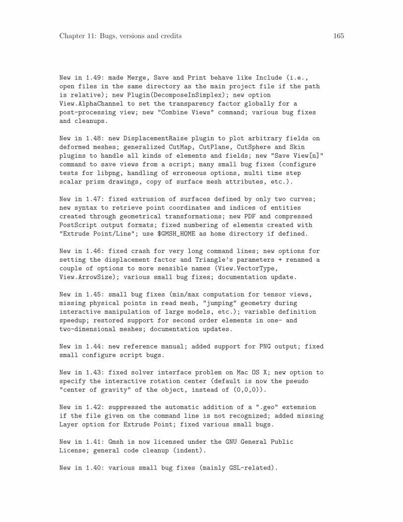
Chapter 11: Bugs, versions and credits 165
New in 1.49: made Merge, Save and Print behave like Include (i.e.,open files in the same directory as the main project file if the pathis relative); new Plugin(DecomposeInSimplex); new optionView.AlphaChannel to set the transparency factor globally for apost-processing view; new "Combine Views" command; various bug fixesand cleanups.
New in 1.48: new DisplacementRaise plugin to plot arbitrary fields ondeformed meshes; generalized CutMap, CutPlane, CutSphere and Skinplugins to handle all kinds of elements and fields; new "Save View[n]"command to save views from a script; many small bug fixes (configuretests for libpng, handling of erroneous options, multi time stepscalar prism drawings, copy of surface mesh attributes, etc.).
New in 1.47: fixed extrusion of surfaces defined by only two curves;new syntax to retrieve point coordinates and indices of entitiescreated through geometrical transformations; new PDF and compressedPostScript output formats; fixed numbering of elements created with"Extrude Point/Line"; use $GMSH_HOME as home directory if defined.
New in 1.46: fixed crash for very long command lines; new options forsetting the displacement factor and Triangle’s parameters + renamed acouple of options to more sensible names (View.VectorType,View.ArrowSize); various small bug fixes; documentation update.
New in 1.45: small bug fixes (min/max computation for tensor views,missing physical points in read mesh, "jumping" geometry duringinteractive manipulation of large models, etc.); variable definitionspeedup; restored support for second order elements in one- andtwo-dimensional meshes; documentation updates.
New in 1.44: new reference manual; added support for PNG output; fixedsmall configure script bugs.
New in 1.43: fixed solver interface problem on Mac OS X; new option tospecify the interactive rotation center (default is now the pseudo"center of gravity" of the object, instead of (0,0,0)).
New in 1.42: suppressed the automatic addition of a ".geo" extensionif the file given on the command line is not recognized; added missingLayer option for Extrude Point; fixed various small bugs.
New in 1.41: Gmsh is now licensed under the GNU General PublicLicense; general code cleanup (indent).
New in 1.40: various small bug fixes (mainly GSL-related).

166 Gmsh 1.63
New in 1.39: removed all non-free routines; more build system work;implemented Von-Mises tensor display for all element types; fixedsmall GUI bugs.
New in 1.38: fixed custom range selection for 3D iso graphs; new buildsystem based on autoconf; new image reading code to import bitmaps aspost-processing views.
New in 1.37: generalized smoothing and cuts of post-processing views;better Windows integration (solvers, external editors, etc.); smallbug fixes.
New in 1.36: enhanced view duplication (one can now use "DuplicataView[num]" in the input file); merged all option dialogs in a newgeneral option window; enhanced discoverability of the view optionmenus; new 3D point and line display; many small bug fixes andenhancements ("Print" format in parser, post-processing statistics,smooth normals, save window positions, restore default options, etc.).
New in 1.35: graphical user interface upgraded to FLTK 1.1 (tooltips,new file chooser with multiple selection, full keyboard navigation,cut/paste of messages, etc.); colors can be now be directly assignedto mesh entities; initial tensor visualization; new keyboard animation(right/left arrow for time steps; up/down arrow for view cycling); newVRML output format for surface meshes; new plugin for sphericalelevation plots; new post-processing file format (version 1.2)supporting quadrangles, hexahedra, prisms and pyramids; transparencyis now enabled by default for post-processing plots; many small bugfixes (read mesh, ...).
New in 1.34: improved surface mesh of non-plane surfaces; fixedorientation of elements in 2D anisotropic algorithm; minor userinterface polish and additions (mostly in post-processing options);various small bug fixes.
New in 1.33: new parameterizable solver interface (allowing up to 5user-defined solvers); enhanced 2D aniso algorithm; 3D initial meshspeedup.
New in 1.32: new visibility browser; better floating point exceptionchecks; fixed infinite looping when merging meshes in project files;various small clean ups (degenerate 2D extrusion, view->reload, ...).
New in 1.31: corrected ellipses; PostScript output update (bettershading, new combined PS/LaTeX output format); more interface polish;fixed extra memory allocation in 2D meshes; Physical Volume handling

Chapter 11: Bugs, versions and credits 167
in unv format; various small fixes.
New in 1.30: interface polish; fix crash when extruding quadrangles.
New in 1.29: translations and rotations can now be combined inextrusions; fixed coherence bug in Extrude Line; various smallbug fixes and additions.
New in 1.28: corrected the ’Using Progression’ attribute fortranfinite meshes to actually match a real geometric progression; newTriangulate plugin; new 2D graphs (space+time charts); betterperformance of geometrical transformations (warning: the numbering ofsome automatically created entities has changed); new text primitivesin post-processing views (file format updated to version 1.1); morerobust mean plane computation and error checks; various other smalladditions and clean-ups.
New in 1.27: added ability to extrude curves with Layers/Recombineattributes; new PointSize/LineWidth options; fixed For/EndFor loops inincluded files; fixed error messages (line numbers+file names) inloops and functions; made the automatic removal of duplicategeometrical entities optional (Geometry.AutoCoherence=0); variousother small bug fixes and clean-ups.
New in 1.26: enhanced 2D anisotropic mesh generator (metricintersections); fixed small bug in 3D initial mesh; added alternativesyntax for built-in functions (for GetDP compatibility); added lineelement display; Gmsh now saves all the elements in the mesh if nophysical groups are defined (or if Mesh.SaveAll=1).
New in 1.25: fixed bug with mixed recombined/non-recombined extrudedmeshes; Linux versions are now build with no optimization, due to bugsin gcc 2.95.X.
New in 1.24: fixed characteristic length interpolation for Splines;fixed edge swapping bug in 3D initial mesh; fixed degenerated case ingeometrical extrusion (ruled surface with 3 borders); fixed generationof degenerated hexahedra and prisms for recombined+extruded meshes;added BSplines creation in the GUI; integrated Jonathan Shewchuk’sTriangle as an alternative isotropic 2D mesh generator; addedAngleSmoothNormals to control sharp edge display with smoothednormals; fixed random crash for lighted 3D iso surfaces.
New in 1.23: fixed duplicate elements generation + non-matchingtetrahedra faces in 3D extruded meshes; better display of displacementmaps; fixed interactive ellipsis construction; generalized boundaryoperator; added new explode option for post-processing views; enhanced

168 Gmsh 1.63
link view behavior (to update only the changed items); added newdefault plugins: Skin, Transform, Smooth; fixed various other smallbugs (mostly in the post-processing module and for extruded meshes).
New in 1.22: fixed (yet another) bug for 2D mesh in the mean plane;fixed surface coherence bug in extruded meshes; new double logarithmicscale, saturate value and smoothed normals option for post-processingviews; plugins are now enabled by default; three new experimentalstatically linked plugins: CutMap (extracts a given iso surface from a3D scalar map), CutPlane (cuts a 3D scalar map with a plane section),CutSphere (cuts a 3D scalar map with a sphere); various other bugfixes, additions and clean-ups.
New in 1.21: fixed more memory leaks; added -opt command line optionto parse definitions directly from the command line; fixed missingscreen refreshes during contour/surface/volume selection; enhancedstring manipulation functions (Sprintf, StrCat, StrPrefix); many othersmall fixes and clean-ups.
New in 1.20: fixed various bugs (memory leaks, functions in includedfiles, solver command selection, ColorTable option, duplicate nodes inextruded meshes (not finished yet), infinite loop on empty views,orientation of recombined quadrangles, ...); reorganized the interfacemenus; added constrained background mesh and mesh visibility options;added mesh quality histograms; changed default mesh colors;reintegrated the old command-line extrusion mesh generator.
New in 1.19: fixed seg. fault for scalar simplex post-processing; newSolver menu; interface for GetDP solver through sockets; fixedmultiple scale alignment; added some options + full optiondescriptions.
New in 1.18: fixed many small bugs and incoherences inpost-processing; fixed broken background mesh in 1D mesh generation.
New in 1.17: corrected physical points saving; fixed parsing of DOSfiles (carriage return problems); easier geometrical selections(cursor change); plugin manager; enhanced variable arrays (sublistselection and affectation); line loop check; New arrow display;reduced number of ’fatal’ errors + better handling in interactivemode; fixed bug when opening meshes; enhanced File->Open behavior formeshes and post-processing views.
New in 1.16: added single/double buffer selection (only useful forUnix versions of Gmsh run from remote hosts without GLX); fixed a bugfor recent versions of the opengl32.dll on Windows, which caused OpenGLfonts not to show up.

Chapter 11: Bugs, versions and credits 169
New in 1.15: added automatic visibility setting during entityselection; corrected geometrical extrusion bug.
New in 1.14: corrected a few bugs in the GUI (most of them wereintroduced in 1.13); added interactive color selection; made theoption database bidirectional (i.e. scripts now correctly update theGUI); default options can now be saved and automatically reloaded atstartup; made some changes to the scripting syntax(PostProcessing.View[n] becomes View[n]; Offset0 becomes OffsetX,etc.); corrected the handling of simple triangular surfaces with largecharacteristic lengths in the 2D isotropic algorithm; added an ASCIIto binary post-processing view converter.
New in 1.13: added support for JPEG output on Windows.
New in 1.12: corrected vector lines in the post-processing parsedformat; corrected animation on Windows; corrected file creation inscripts on Windows; direct affectation of variable arrays.
New in 1.11: corrected included file loading problem.
New in 1.10: switched from Motif to FLTK for the GUI. Many smalltweaks.
New in 1.00: added PPM and YUV output; corrected nested If/Endif;Corrected several bugs for pixel output and enhanced GIF output(dithering, transparency); slightly changed the post-processing fileformat to allow both single and double precision numbers.
New in 0.999: added JPEG output and easy MPEG generation (see t8.geoin the tutorial); clean up of export functions; small fixes; Linuxversions are now compiled with gcc 2.95.2, which should fix theproblems encountered with Mandrake 7.2.
New in 0.998: corrected bug introduced in 0.997 in the generation ofthe initial 3D mesh.
New in 0.997: corrected bug in interactive surface/volume selection;Added interactive symmetry; corrected geometrical extrusion withrotation in degenerated or partially degenerated cases; corrected bugin 2D mesh when meshing in the mean plane.
New in 0.996: arrays of variables; enhanced Printf and Sprintf;Simplified options (suppression of option arrays).
New in 0.995: totally rewritten geometrical database (performance has

170 Gmsh 1.63
been drastically improved for all geometrical transformations, andmost notably for extrusion). As a consequence, the internal numberingof geometrical entities has changed: this will cause incompatibilitieswith old .geo files, and will require a partial rewrite of your old.geo files if these files made use of geometrical transformations. Thesyntax of the .geo file has also been clarified. Many additions forscripting purposes. New extrusion mesh generator. Preliminary versionof the coupling between extruded and Delaunay meshes. New option andprocedural database. All interactive operations can be scripted in theinput files. See the last example in the tutorial for an example. Manystability enhancements in the 2D and 3D mesh algorithms. Performanceboost of the 3D algorithm. Gmsh is still slow, but the performancebecomes acceptable. An average 1000 tetrahedra/second is obtained on a600Mhz computer for a mesh of one million tetrahedra. New anisotropic2D mesh algorithm. New (ASCII and binary) post-processing file formatand clarified mesh file format. New handling for interactive rotations(trackball mode). New didactic interactive mesh construction (watchthe Delaunay algorithm in real time on complex geometries: that’sexciting ;-). And many, many bug fixes and cleanups.
New in 0.992: corrected recombined extrusion; corrected ellipses; addedsimple automatic animation of post-processing maps; fixed various bugs.
New in 0.991: fixed a serious allocation bug in 2D algorithm, whichcaused random crashes. All users should upgrade to 0.991.
New in 0.990: bug fix in non-recombined 3D transfinite meshes.
New in 0.989: added ability to reload previously saved meshes; somenew command line options; reorganization of the scale menu; GIFoutput.
New in 0.987: fixed bug with smoothing (leading to the possiblegeneration of erroneous 3d meshes); corrected bug for mixed 3D meshes;moved the ’toggle view link’ option to Opt->Postprocessing_Options.
New in 0.986: fixed overlay problems; SGI version should now also runon 32 bits machines; fixed small 3d mesh bug.
New in 0.985: corrected colormap bug on HP, SUN, SGI and IBM versions;corrected small initialization bug in postscript output.
New in 0.984: corrected bug in display lists; added some options inOpt->General.
New in 0.983: corrected some seg. faults in interactive mode; correctedbug in rotations; changed default window sizes for better match with

Chapter 11: Bugs, versions and credits 171
1024x768 screens (default X resources can be changed: see ex03.geo).
New in 0.982: lighting for mesh and post-processing; corrected 2ndorder mesh on non plane surfaces; added example 13.
11.3 Credits
$Id: CREDITS,v 1.34 2006/01/06 00:34:33 geuzaine Exp $
Gmsh is copyright (C) 1997-2006
Christophe Geuzaine<christophe.geuzaine at case.edu>
and
Jean-Francois Remacle<remacle at gce.ucl.ac.be>
Major code contributions to Gmsh have been provided by Nicolas Tardieu<ntardieu at giref.ulaval.ca> (help with the GSL integration, new "STLto elementary geometry" interface, Netgen integration).
Other code contributors include: David Colignon <David.Colignon atulg.ac.be> for new colormaps; Patrick Dular <patrick.dular atulg.ac.be> for transfinite mesh bug fixes; Laurent Stainier<l.stainier at ulg.ac.be> for the eigenvalue solvers and for help withthe MacOS port and the tensor display code; Pierre Badel <badel atfreesurf.fr> for help with the GSL integration; Marc Ume <Marc.Ume atdigitalgraphics.be> for the original list code; Matt Gundry <mjgundryat faa-engineers.com> for the Plot3d mesh format; Jozef Vesely <veselyat gjh.sk> for the Tetgen integration.
The AVL tree code (DataStr/avl.*) and the YUV image code(Graphics/gl2yuv.*) are copyright (C) 1988-1993, 1995 The Regents ofthe University of California. Permission to use, copy, modify, anddistribute this software and its documentation for any purpose andwithout fee is hereby granted, provided that the above copyrightnotice appear in all copies and that both that copyright notice andthis permission notice appear in supporting documentation, and thatthe name of the University of California not be used in advertising orpublicity pertaining to distribution of the software without specific,written prior permission. The University of California makes norepresentations about the suitability of this software for anypurpose. It is provided "as is" without express or implied warranty.

172 Gmsh 1.63
The trackball code (Common/Trackball.*) is copyright (C) 1993, 1994,Silicon Graphics, Inc. ALL RIGHTS RESERVED. Permission to use, copy,modify, and distribute this software for any purpose and without feeis hereby granted, provided that the above copyright notice appear inall copies and that both the copyright notice and this permissionnotice appear in supporting documentation, and that the name ofSilicon Graphics, Inc. not be used in advertising or publicitypertaining to distribution of the software without specific, writtenprior permission.
The GIF and PPM routines (Graphics/gl2gif.cpp) are based on codecopyright (C) 1989, 1991, Jef Poskanzer. Permission to use, copy,modify, and distribute this software and its documentation for anypurpose and without fee is hereby granted, provided that the abovecopyright notice appear in all copies and that both that copyrightnotice and this permission notice appear in supporting documentation.This software is provided "as is" without express or implied warranty.
The colorbar widget (Fltk/Colorbar_Window.cpp) was inspired by codefrom the Vis5d program for visualizing five dimensional gridded datasets, copyright (C) 1990-1995, Bill Hibbard, Brian Paul, Dave Santek,and Andre Battaiola.
This version of Gmsh may contain code (in the contrib/ANNsubdirectory) copyright (C) 1997-2005 University of Maryland and SunilArya and David Mount: check the configuration options.
This version of Gmsh may contain code (in the contrib/MathEvalsubdirectory) based on GNU libmatheval, copyright (C) 1999, 2002, 2003Free Software Foundation, Inc: check the configuration options.
This version of Gmsh may contain code (in the contrib/Netgensubdirectory) copyright (C) 1994-2004, Joachim Sch"oberl: check theconfiguration options.
This version of Gmsh may contain code (in the contrib/Trianglesubdirectory) copyright (C) 1993, 1995, 1997, 1998, 2002, JonathanRichard Shewchuk: check the configuration options.
This version of Gmsh may contain code (in the contrib/Tetgensubdirectory) copyright (C) 2002, 2004 Hang Si: check theconfiguration options.
This version of Gmsh may contain code (in the contrib/Metissubdirectory) written by George Karypis (karypis at cs.umn.edu),copyright (C) 1998, Regents of the University of Minnesota: check the

Chapter 11: Bugs, versions and credits 173
configuration options.
Special thanks to Bill Spitzak <spitzak at users.sourceforge.net>,Michael Sweet <easysw at users.sourceforge.net>, Matthias Melcher <mmat matthiasm.com> and others for the Fast Light Tool Kit on whichGmsh’s GUI is based. See http://www.fltk.org for more info on thisexcellent object-oriented, cross-platform toolkit.
Thanks to the following folks who have contributed by providing freshideas on theoretical or programming topics, who have sent patches,requests for changes or improvements, or who gave us access to exoticmachines for testing Gmsh: Juan Abanto <juanabanto at yahoo.com>,Olivier Adam <o.adam at ulg.ac.be>, Guillaume Alleon <guillaume.alleonat airbus.aeromatra.com>, Eric Bechet <eric.bechet at epost.de>,Laurent Champaney <laurent.champaney at meca.uvsq.fr>, Pascal Dupuis<Pascal.Dupuis at esat.kuleuven.ac.be>, Philippe Geuzaine <geuzaine atgnat.colorado.edu>, Johan Gyselinck <johan.gyselinck at ulg.ac.be>,Francois Henrotte <fhenrott at esat.kuleuven.ac.be>, Benoit Meys<bmeys at techspace-aero.be>, Nicolas Moes <moes attam9.mech.nwu.edu>, Osamu Nakamura <naka athasaki.sumitomometals.co.jp>, Chad Schmutzer <schmutze atacm.caltech.edu>, Jean-Luc Fl’ejou <jean-luc.flejou at edf.fr>, XavierDardenne <dardenne at tele.ucl.ac.be>, Christophe Prud’homme <prudhommat debian.org>, Sebastien.Clerc <Sebastien.Clerc at space.alcatel.fr>,Jose Miguel Pasini <jmp84 at cornell.edu>, Philippe Lussou <plussou atnecs.fr>, Jacques Kools <JKools at veeco.com>, Bayram Yenikaya<yenikaya at math.umn.edu>, Peter Hornby <p.hornby at arrc.csiro.au>,Krishna Mohan Gundu <gkmohan at gmail.com>, Christopher Stott <C.Stottat surrey.ac.uk>, Timmy Schumacher <Tim.Schumacher at colorado.edu>,Carl Osterwisch <osterwischc at asme.org>, Bruno Frackowiak<bruno.frackowiak at onecert.fr>.

174 Gmsh 1.63

Appendix A: Tips and tricks 175
Appendix A Tips and tricks
• Install the ‘info’ version of this user’s guide! On your (Unix) system, this can beachieved by1. copying all ‘gmsh.info*’ files to the place where your info files live (usually
‘/usr/info’), and2. issuing the command install-info /usr/info/gmsh.info /usr/info/dir.
You will then be able to access the documentation with the command info gmsh.Note that particular sections (‘nodes’) can be accessed directly. For example, infogmsh surfaces or info gmsh surf will take you directly to Section 3.1.3 [Surfaces],page 41.
• Use emacs to edit your files, and load the C++ mode! This permits automatic syntaxhighlighting and easy indentation. Automatic loading of the C++ mode for ‘.geo’ filescan be achieved by adding the following command in your .emacs file: (setq auto-mode-alist (append ’(("\\.geo$" . c++-mode)) auto-mode-alist)).
• Define common geometrical objects and options in separate files, reusable in all yourproblem definition structures.
• Save your preferred options with ‘Tools->Options->Save’. To reset default options, erasethe General.OptionsFileName (usually ‘.gmsh-options’ in your home directory) oruse the ‘Restore default options’ button in ‘Tools->Options->General->Output’.
• In the graphical user interface:– dragging the mouse in a numeric input field slides the value. The left button moves
one step per pixel, the middle by 10 * step, and the right button by 100 * step;– selecting the content of an input field, or lines in the message console (‘Tools-
>Message Console’), copies the selected text to the clipboard;• Read Appendix B [Frequently asked questions], page 177...

176 Gmsh 1.63

Appendix B: Frequently asked questions 177
Appendix B Frequently asked questions
$Id: FAQ,v 1.68 2005/11/22 03:15:49 geuzaine Exp $
This is the Gmsh FAQ
********************************************************************
Section 1: The basics
* 1.1 What is Gmsh?
Gmsh is an automatic three-dimensional finite element mesh generator,primarily Delaunay, with built-in pre- and post-processingfacilities. Its design goal is to provide a simple meshing tool foracademic problems with parametric input and advanced visualizationcapabilities.
* 1.2 What are the terms and conditions of use?
Gmsh is distributed under the terms of the GNU General PublicLicense. See the file ’doc/LICENSE’ for more information, or go to theGNU foundation’s web site at http://www.gnu.org.
* 1.3 What does ’Gmsh’ mean?
Nothing ;-)
(Note that in the US, people tend to pronounce ’Gmsh’ as’Gee-mesh’. Yeehaa!)
* 1.4 Where can I find more information?
http://www.geuz.org/gmsh/ is the primary location to obtaininformation about Gmsh. You will for example find a complete referencemanual as well as a searchable archive of the Gmsh mailing list([email protected]) on this webpage.
********************************************************************
Section 2: Installation
* 2.1 Which OSes does Gmsh run on?
Gmsh is known to run on Windows 95/98/NT/2000/XP, Linux, Mac OS X,Compaq Tru64 Unix (aka OSF1, aka Digital Unix), Sun OS, IBM AIX, SGIIRIX, FreeBSD and HP-UX. It should compile on any Unix-like operating
178 Gmsh 1.63
system, provided that you have access to a recent C and C++ compiler.
* 2.2 Are there additional requirements to run Gmsh?
You should have the OpenGL libraries installed on your system, and inthe path of the library loader. A free replacement for OpenGL can befound at http://www.mesa3d.org.
* 2.3 What do I need to compile Gmsh from the sources?
You need a C and a C++ compiler (e.g. the GNU compilers gcc and g++)as well as the GSL (version 1.2 or higher; freely available fromhttp://sources.redhat.com/gsl/) and FLTK (version 1.1.x, configuredwith OpenGL support; freely available from http://www.fltk.org).You’ll also need the jpeg library if you want to save jpeg images, andthe libpng and zlib libraries if you want to save png images.
Under Windows, you will need the Cygwin tools and compilers (freelyavailable from http://www.cygwin.com), as well as a "cygwin-enabled"version of FLTK (i.e., you have to configure FLTK with ’./configure--enable-cygwin’).
* 2.4 How do I compile Gmsh?
Just type ’./configure; make; make install’. If you change someconfiguration options (type ’./configure --help’ to get the list ofall available choices), don’t forget to do ’make clean’ beforerebuilding Gmsh.
********************************************************************
Section 3: General problems
* 3.1 Gmsh (from a binary distribution) complains about missinglibraries.
Try ’ldd gmsh’ (or ’otool -L gmsh’ on Mac OS X) to check if all therequired shared libraries are installed on your system. If not,install them. If it still doesn’t work, recompile Gmsh from thesources.
* 3.2 Gmsh keeps re-displaying its graphics when other windowspartially hide the graphical window.
Disable opaque move in your window manager.
* 3.3 The graphics display very slowly.

Appendix B: Frequently asked questions 179
Are you are executing Gmsh from a remote host (via the network)without GLX? You should turn double buffering off (with the ’-nodb’command line option).
* 3.4 There is an ugly "ghost triangulation" in the vectorPostScript/PDF files generated by Gmsh!
No, there isn’t. This "ghost triangulation" is due to the fact thatmost PostScript previewers nowadays antialias the graphic primitiveswhen they display the page on screen. (For example, in gv, you candisable antialising with the ’State->Antialias’ menu.) You should notsee this ghost triangulation in the printed output (on paper).
* 3.5 How can I save GIF, JPEG, ..., images?
Just choose the appropriate format in ’File->Save As’.
* 3.6 How can I save MPEG, AVI, ..., animations?
See question 7.9.
********************************************************************
Section 4: Geometry module
* 4.1 Does Gmsh support NURBS curves/surfaces?
Not yet.
* 4.2 Gmsh is very slow when I use many transformations (Translate,Rotate, Symmetry, Extrude, etc. ). What’s wrong?
The default behavior of Gmsh is to check and suppress all duplicateentities (points, lines and surfaces) each time a transformationcommand is issued. This can slow down things a lot if manytransformations are performed. There are two solutions to thisproblem:- you may save the unrolled geometry in another file (e.g. with
gmsh file.geo -0 > flat.geo), and use this new file for subsequentcomputations;
- you may set the ’Geometry.AutoCoherence’ option to 0. This willprevent any automatic duplicate check/replacement. If you stillneed to remove the duplicates entities, simply add ’Coherence;’ atstrategic locations in your geo files (e.g. before the creation ofline loops, etc.).

180 Gmsh 1.63
* 4.3 How can I display only selected parts of my model?
By using ’Tool->Visibility’:
- In the ’Browser’ tab, you can select which group of entities to show(several entities can be selected at once by dragging the mouse or byholding the Ctrl and Shift keys while clicking). There are three mainmodes: ’Elementary’, in which the numbers in the list correspond toelementary geometrical entities; ’Physical’, in which the numbers inthe list correspond to physical entities; and ’Partitions’, in whichthe numbers in the list correspond to indices of mesh partitions (formulti-domain meshes read from "new" .msh files). If ’Geometry+Mesh’ isselected, the selection applies to both the geometrical entities andtheir associated meshes; if ’Mesh’ is selected, the selection appliesonly to the mesh; if ’Geometry’ is selected, the selection appliesonly to the geometry. If the ’Recursive’ option is set, selecting anentity implies that all the entities that are used to construct it(all the "boundaries") are selected too, recursively. For example, if’Recursive’ is set, selecting a surface will automatically select itsboundary curves, as well as the boundaries of these curves (i.e.,points). If ’Recursive’ is not set, only the surface (the dashedcross) would be shown.
- In the ’Numeric Input’ tab, you can choose to show or hide anyentity or mesh element by giving its number. You can also use the "*"character to select all the entities/elements at once. For example, toshow only the mesh element 13245 in the mesh, you would enter "*" inthe ’Element’ input field and click on ’Hide’ (this will hide all themesh elements); and then enter "13245" in the ’Element’ input fieldand click on ’Show’ (this will show the element 13245). To show otherelement, you would just enter another number in the input field, clickon ’Show’, etc.
********************************************************************
Section 5: Mesh module
* 5.1 What should I do when the 2D unstructured algorithm fails?
Try one of the other 2D algorithms, e.g.:- on the command line: ’gmsh -algo tri’- in the interface: ’Tools->Options->Mesh->2D->Isotropic algorithm (Triangle)’- in input files: ’Mesh.Algorithm = 3’The old 2D algorithm may disappear once all its features areintegrated in the new ones, so please don’t send bug reports on theold algorithm anymore.

Appendix B: Frequently asked questions 181
* 5.2 The new 2D unstructured algorithms also fail! Then what?
Send us your geometry, and we will investigate. Please keep thefollowing in mind though: 2D (surface) meshes are generated byprojecting the 2D mesh in a "mean plane" of the surface. This givesnice results only if the surface curvature is small enough. Otherwiseyou must cut the surface into several pieces (patches). For example,using half circles to define a cylinder will fail with theunstructured algorithm: you should define arcs with angles smallerthan Pi, and thus define the cylinder with at least three patches.
* 5.3 What should I do when the 3D unstructured algorithm fails?
The 3D algorithm is still very experimental. Try to change somecharacteristic lengths in your input file to generate meshes thatbetter suit the geometrical details of your structure.
* 5.4 I changed the characteristic lengths, but the 3D algorithm stilldoes not work. What should I do?
Buy a professional mesh generator ;-) You can also try to use Netgeninstead of the default algorithm for the 3D mesh. Note that allsurface meshes have to be oriented with exterior normals in this case.
* 5.5 The 3D algorithm is reaaaaally slow. Can you improve it?
We are working on it. But since we have a (very) limited amount oftime to spend on the development of Gmsh, this may take a while. Forvery big meshes, see the answer to the previous question...
* 5.6 The quality of the elements generated by the 3D algorithm isvery bad.
Upgrade to Gmsh >= 1.54 and use ’Optimize quality’. If badly shapedelements still exist due to the surface recovery step, you can try touse Netgen instead of the default algorithm for the 3D mesh. Note thatall surface meshes have to be oriented with exterior normals in thiscase.
* 5.7 Non-recombined 3D extruded meshes sometimes fail.
The swapping algorithm is not very clever at the moment. Try to changethe surface mesh a bit, or recombine your mesh to generate prisms orhexahedra instead of tetrahedra.
* 5.8 Tools->Visibility does not seem to work with extruded meshes.

182 Gmsh 1.63
This is fixed in Gmsh >= 1.54. However, when region numbers areexplicitly assigned to mesh entities in the extrude commands (whichpartially destroys the geometry/mesh relationship), the ’Visibility’tool will only work as expected when displaying elementaryentities. In this particular case, the only solution to visualizeextruded physical entities is to save the mesh, and to read it again.
* 5.9 Does Gmsh support curved elements?
Yes, Gmsh can generate both 1st order and 2nd order elements. Togenerate second order elements, click on ’Second order’ in the meshmenu after the mesh is completed. To always generate 2nd orderelements, select ’Generate second order elements’ in the mesh optionpanel. From the command line, you can also use ’-order 2’.
* 5.10 Can I import an existing surface mesh in Gmsh and use it tobuild a 3D mesh?
Yes, see for example ’demos/sphere-discrete.geo’. Note that Gmshdoes not currently modify the surface mesh that you provide in thisway, so this surface mesh has to be conform (without gaps, hangingnodes, etc.) and must contain surface elements having the finaldesired sizes.
Gmsh can also import discrete geometries in the form of STLtriangulations, and remesh these to respect certain constraints. Thisis an experimental and undocumented feature as of this writing(version 1.61).
* 5.11 How do I define boundary conditions or material properties inGmsh?
By design, Gmsh does not try to incorporate every possible definitionof boundary conditions or material properties--this is a job best leftto the solver. Instead, Gmsh provides a simple mechanism to tag groupsof elements, and it is up to the solver to interpret these tags asboundary conditions, materials, etc. Associating tags with elements inGmsh is done by defining Physical entities (Physical Points, PhysicalLines, Physical Surfaces and Physical Volumes): see the referencemanual as well as the tutorials (in particular ’tutorial/t1.geo’) fora detailed description and some examples.
* 5.12 How can I display only the mesh associated with selectedgeometrical entities?
See question 4.3.
Appendix B: Frequently asked questions 183
* 5.13 How can I "explore" a mesh (for example, to see inside acomplex structure)?
You can use ’Tools->Clipping Planes’ to extract the region ofinterest. You can define up to 6 clipping planes in Gmsh (i.e., enoughto define a "cube" inside your model) and each plane can clip eitherthe geometry, the mesh, the post-processing views, or any combinationof the above. The clipping planes are defined using the fourcoefficients A,B,C,D of the equation A*x+B*y+C*y+D=0, which can beadjusted interactively by dragging the mouse in the inputfields. There is also one additional clipping plane available for"cutting" only the mesh (by keeping entire elements), in’Tools->Options->Mesh->Cut Plane’.
* 5.14 What is the signification of Rho, Eta and Gamma inTools->Statistics?
They measure the quality of the tetrahedra in a mesh:
Rho ~ min_edge_length / max_edge_lengthEta ~ volume^(2/3) / sum_edge_length^2Gamma ~ volume / sum_face_area / max_edge_length
For the exact definitions, look at Mesh/Element.cpp andMesh/Simplex.cpp.
The graphs plot the the number of elements vs the quality measure.
********************************************************************
Section 6: Solver module
* 6.1 How do I integrate my own solver with Gmsh?
If you want to simply launch a program from within Gmsh, just edit theoptions to define your solver commands (e.g. Solver.Name0,Solver.Executable0, etc.), and set the ClientServer option to zero(e.g. Solver.ClientServer0 = 0).
If you want your solver to interact with Gmsh (for error messages,option definitions, post-processing, etc.), you will need to link yoursolver with the GmshClient routines and add the appropriate functioncalls inside your program. You will of course also need to define yoursolver commands in an option file, but this time you should set theClientServer variable to 1 (e.g. Solver.ClientServer = 1). C, C++,Perl and Python solver examples are available in the sourcedistribution in the ’utils/solvers’ directory.

184 Gmsh 1.63
* 6.2 On Windows, Gmsh does not seem to find the solverexecutable. What’s wrong?
The solver executable (for example, ’getdp.exe’) has to be in yourpath. If not, simply go to the solver options (for example,’Solver->GetDP->Options->Executable’) to specify its location.
On recent versions of Microsoft Windows (XP SP2), it seems that youneed to execute the solver (e.g. launch ’getdp.exe’) at least onceindependently first in order to authorize future executions.
* 6.3 Can I launch Gmsh from my solver (instead of launching my solverfrom Gmsh) in order to monitor a solution?
Sure. A simple C program showing how to do this is given in’utils/misc/callgmsh.c’.
* 6.4 Is it possible for Gmsh top listen to an external program notlaunched from Gmsh?
Yes: just create a program as described in 6.1 above (you can skip theoption file creation). Then run ’gmsh -listen’ and Gmsh will listenfor the program on the Solver.SocketName socket.
********************************************************************
Section 7: Post-processing module
* 7.1 How do I compute a section of a plot?
Use ’View->Plugins->Cut Plane’.
* 7.2 Can I save an isosurface to a file?
Yes: first run ’View->Plugins->Cut Map’ to extract the isosurface,then use ’View->Save As’ to save the new view.
* 7.3 Can Gmsh generate isovolumes?
Yes, with the CutMap plugin (set the ExtractVolume option to -1 or 1to extract the negative or positive levelset).
* 7.4 How do I animate my plots?
If the views contain multiple time steps, you can press the ’play’button at the bottom of the graphic window, or change the time step by

Appendix B: Frequently asked questions 185
hand in the view option panel. You can also use the left and rightarrow keys on your keyboard to change the time step in all visibleviews in real time.
If you want to loop through different views instead of time steps, youcan use the ’Loop through views instead of time steps’ option in theview option panel, or use the up and down arrow keys on your keyboard.
* 7.5 How do I visualize a deformed mesh?
Load a vector view containing the displacement field, and set ’Vectordisplay’ to ’Displacement’ in View->Options->Aspect. If thedisplacement is too small (or too large), you can scale it with the’Displacement factor’ option. (Remember that you can drag the mouse inall numeric input fields to slide the value!)
Another option is to use the "general transformation expressions" (inView->Options->Offset) on a scalar view, with the displacement mapselected as the data source.
* 7.6 Can I visualize a field on a deformed mesh?
Yes, there are several ways to do that.
The easiest is to load two views: the first one containing adisplacement field (a vector view that will be used to deform themesh), and the second one containing the field you want to display(this view has to contain the same number of elements as thedisplacement view). You should then set ’Vector display’ to’Displacement’ in the first view, as well as set ’Data source’ topoint to the second view. (You might want to make the second viewinvisible, too. If you want to amplify or decrease the amount ofdeformation, just modify the ’Displacement factor’ option.)
Another solution is to use the ’General transformation expressions’(in ’View->Options->Offset’) on the field you want to display, withthe displacement map selected as the data source.
And yet another solution is to use the DiplacementRaise plugin.
* 7.7 Can I color the arrows representing a vector field with datafrom a scalar field?
Yes: load both the vector and the scalar fields (the two views musthave the same number of elements) and, in the vector field options,select the scalar view in ’Data source’.

186 Gmsh 1.63
* 7.8 Can I color isovalue surfaces with data from another scalarview?
Yes, using either the CutMap plugin (with the ’dView’ option) or theEvaluate plugin.
* 7.9 Is there a way to save animations?
Yes, using scripts. Have a look at ’tutorial/t8.geo’ or’demos/anim.script’ for some examples.
* 7.10 Is there a way to visualize only certain components ofvector/tensor fields?
Yes, using ’View->Plugin->Extract’.
* 7.11 Can I do arithmetic operations on a view? Can I performoperations involving different views?
Yes, with the Evaluate plugin.
* 7.12 Some plugins seem to create empty views. What’s wrong?
There can be several reasons:
- the plugin might be written for specific element types only (forexample, only for scalar triangles or tetrahedra). In that case, youshould transform your view before running the plugin (you can usePlugin(DecomposeinSimplex) to transform all quads, hexas, prisms andpyramids into triangles and tetrahedra).
- the plugin might expect a mesh while all you provide is a pointcloud. In 2D, you can use Plugin(Triangulate) to transform a pointcloud into a triangulated surface. A 3D version of this plugin isnot available yet but it is on our TODO list.
- the input parameters are out of range.
In any case, you can automatically remove all empty views with’View->Remove->Empty Views’ in the GUI, or with "Delete Empty Views;"in a script.
* 7.13 My code generates data "time step by time step", and thuscannot easily output Gmsh’s multi-time-step post-processing files,where the values for all the time steps are given per element. How canI use Gmsh’s post-processor in this situation?

Appendix B: Frequently asked questions 187
Just create one view for each time step: Gmsh can handle an arbitrarynumber of views and it can deal with these separate views asefficiently as with a single multi-time-step view. The onlydisadvantage is that the total amount of disk space used is greater(since the node data is repeated for each time step).
In practice, depending on the size of the data set, you may want tostore all the views in a single file or create one separate file foreach view, which you can then load selectively (and thus reduce thememory required for the analysis). In any case you can use’Tools->Options->Post-processing->View links’ to apply options tomultiple views at once, and the up and down arrow keys to loop through(animate) the views (instead of the left and right arrow keys formulti-time-step views).
Also note that if all the views are based on the same grid, Gmsh cancombine the separate views into a multi-time-step view by using the’View->Combine->Time Steps’ menu, or by using the ’-combine’ commandline option.
* 7.14 How can I see "inside" a complicated post-processing view?
See question 5.13.
When viewing 3D scalar fields, you can also modify the colormap(’Tools->Options->View->Map’) to make the iso-surfaces "transparent":either by holding ’Ctrl’ while dragging the mouse to draw the alphachannel by hand, or by using the ’a’, ’Ctrl+a’, ’p’ and ’Ctrl+p’keyboard shortcuts.
Yet another (destructive) option is to use the ExtractVolume option inthe CutSphere or CutPlane plugins.
* 7.15 I am loading a valid 3D scalar view but Gmsh does not displayanything!
In versions < 1.61, the default drawing mode for 3D scalar views wasto draw iso-surfaces. If your data set was constant per element, Gmshwould not draw anything (a fix for this would be to runPlugin(Smooth), which would average the data on the nodes of thegrid)... This behavior has changed in version 1.61, and Gmsh now drawsthe solution on the boundary of the elements by default. Iso-surfacesare of course still available by setting ’Intervals type’ to’Iso-values’ in ’Tools->Options->View->Range’.
Note that the most efficient way to visualize the dataset on theboundary of the elements is to run Plugin(Skin) on the view: this will

188 Gmsh 1.63
extract the boundary of the dataset and only draw the data on thisboundary.

Appendix C: License 189
Appendix C License
GNU General Public License
Version 2, June 1991
Copyright c© 1989, 1991 Free Software Foundation, Inc.59 Temple Place - Suite 330, Boston, MA 02111-1307, USA
Everyone is permitted to copy and distribute verbatim copiesof this license document, but changing it is not allowed.
Preamble
The licenses for most software are designed to take away your freedom to share and changeit. By contrast, the GNU General Public License is intended to guarantee your freedomto share and change free software—to make sure the software is free for all its users. ThisGeneral Public License applies to most of the Free Software Foundation’s software and toany other program whose authors commit to using it. (Some other Free Software Foundationsoftware is covered by the GNU Library General Public License instead.) You can apply itto your programs, too.When we speak of free software, we are referring to freedom, not price. Our General PublicLicenses are designed to make sure that you have the freedom to distribute copies of freesoftware (and charge for this service if you wish), that you receive source code or can getit if you want it, that you can change the software or use pieces of it in new free programs;and that you know you can do these things.To protect your rights, we need to make restrictions that forbid anyone to deny you theserights or to ask you to surrender the rights. These restrictions translate to certain respon-sibilities for you if you distribute copies of the software, or if you modify it.For example, if you distribute copies of such a program, whether gratis or for a fee, youmust give the recipients all the rights that you have. You must make sure that they, too,receive or can get the source code. And you must show them these terms so they knowtheir rights.We protect your rights with two steps: (1) copyright the software, and (2) offer you thislicense which gives you legal permission to copy, distribute and/or modify the software.Also, for each author’s protection and ours, we want to make certain that everyone un-derstands that there is no warranty for this free software. If the software is modified bysomeone else and passed on, we want its recipients to know that what they have is not theoriginal, so that any problems introduced by others will not reflect on the original authors’reputations.Finally, any free program is threatened constantly by software patents. We wish to avoidthe danger that redistributors of a free program will individually obtain patent licenses, ineffect making the program proprietary. To prevent this, we have made it clear that anypatent must be licensed for everyone’s free use or not licensed at all.The precise terms and conditions for copying, distribution and modification follow.

190 Gmsh 1.63
TERMS AND CONDITIONS FOR COPYING,DISTRIBUTION AND MODIFICATION
0. This License applies to any program or other work which contains a notice placedby the copyright holder saying it may be distributed under the terms of this GeneralPublic License. The “Program”, below, refers to any such program or work, and a“work based on the Program” means either the Program or any derivative work undercopyright law: that is to say, a work containing the Program or a portion of it, eitherverbatim or with modifications and/or translated into another language. (Hereinafter,translation is included without limitation in the term “modification”.) Each licensee isaddressed as “you”.
Activities other than copying, distribution and modification are not covered by thisLicense; they are outside its scope. The act of running the Program is not restricted,and the output from the Program is covered only if its contents constitute a work basedon the Program (independent of having been made by running the Program). Whetherthat is true depends on what the Program does.
1. You may copy and distribute verbatim copies of the Program’s source code as youreceive it, in any medium, provided that you conspicuously and appropriately publishon each copy an appropriate copyright notice and disclaimer of warranty; keep intactall the notices that refer to this License and to the absence of any warranty; and giveany other recipients of the Program a copy of this License along with the Program.
You may charge a fee for the physical act of transferring a copy, and you may at youroption offer warranty protection in exchange for a fee.
2. You may modify your copy or copies of the Program or any portion of it, thus forming awork based on the Program, and copy and distribute such modifications or work underthe terms of Section 1 above, provided that you also meet all of these conditions:
a. You must cause the modified files to carry prominent notices stating that youchanged the files and the date of any change.
b. You must cause any work that you distribute or publish, that in whole or in partcontains or is derived from the Program or any part thereof, to be licensed as awhole at no charge to all third parties under the terms of this License.
c. If the modified program normally reads commands interactively when run, youmust cause it, when started running for such interactive use in the most ordinaryway, to print or display an announcement including an appropriate copyright noticeand a notice that there is no warranty (or else, saying that you provide a warranty)and that users may redistribute the program under these conditions, and tellingthe user how to view a copy of this License. (Exception: if the Program itself isinteractive but does not normally print such an announcement, your work basedon the Program is not required to print an announcement.)
These requirements apply to the modified work as a whole. If identifiable sectionsof that work are not derived from the Program, and can be reasonably consideredindependent and separate works in themselves, then this License, and its terms, do notapply to those sections when you distribute them as separate works. But when youdistribute the same sections as part of a whole which is a work based on the Program,the distribution of the whole must be on the terms of this License, whose permissions

Appendix C: License 191
for other licensees extend to the entire whole, and thus to each and every part regardlessof who wrote it.Thus, it is not the intent of this section to claim rights or contest your rights towork written entirely by you; rather, the intent is to exercise the right to control thedistribution of derivative or collective works based on the Program.In addition, mere aggregation of another work not based on the Program with theProgram (or with a work based on the Program) on a volume of a storage or distributionmedium does not bring the other work under the scope of this License.
3. You may copy and distribute the Program (or a work based on it, under Section 2)in object code or executable form under the terms of Sections 1 and 2 above providedthat you also do one of the following:a. Accompany it with the complete corresponding machine-readable source code,
which must be distributed under the terms of Sections 1 and 2 above on a mediumcustomarily used for software interchange; or,
b. Accompany it with a written offer, valid for at least three years, to give any thirdparty, for a charge no more than your cost of physically performing source distri-bution, a complete machine-readable copy of the corresponding source code, to bedistributed under the terms of Sections 1 and 2 above on a medium customarilyused for software interchange; or,
c. Accompany it with the information you received as to the offer to distribute cor-responding source code. (This alternative is allowed only for noncommercial dis-tribution and only if you received the program in object code or executable formwith such an offer, in accord with Subsection b above.)
The source code for a work means the preferred form of the work for making modifi-cations to it. For an executable work, complete source code means all the source codefor all modules it contains, plus any associated interface definition files, plus the scriptsused to control compilation and installation of the executable. However, as a spe-cial exception, the source code distributed need not include anything that is normallydistributed (in either source or binary form) with the major components (compiler,kernel, and so on) of the operating system on which the executable runs, unless thatcomponent itself accompanies the executable.If distribution of executable or object code is made by offering access to copy froma designated place, then offering equivalent access to copy the source code from thesame place counts as distribution of the source code, even though third parties are notcompelled to copy the source along with the object code.
4. You may not copy, modify, sublicense, or distribute the Program except as expresslyprovided under this License. Any attempt otherwise to copy, modify, sublicense ordistribute the Program is void, and will automatically terminate your rights under thisLicense. However, parties who have received copies, or rights, from you under thisLicense will not have their licenses terminated so long as such parties remain in fullcompliance.
5. You are not required to accept this License, since you have not signed it. However,nothing else grants you permission to modify or distribute the Program or its derivativeworks. These actions are prohibited by law if you do not accept this License. Therefore,by modifying or distributing the Program (or any work based on the Program), you
192 Gmsh 1.63
indicate your acceptance of this License to do so, and all its terms and conditions forcopying, distributing or modifying the Program or works based on it.
6. Each time you redistribute the Program (or any work based on the Program), therecipient automatically receives a license from the original licensor to copy, distributeor modify the Program subject to these terms and conditions. You may not imposeany further restrictions on the recipients’ exercise of the rights granted herein. You arenot responsible for enforcing compliance by third parties to this License.
7. If, as a consequence of a court judgment or allegation of patent infringement or for anyother reason (not limited to patent issues), conditions are imposed on you (whether bycourt order, agreement or otherwise) that contradict the conditions of this License, theydo not excuse you from the conditions of this License. If you cannot distribute so asto satisfy simultaneously your obligations under this License and any other pertinentobligations, then as a consequence you may not distribute the Program at all. Forexample, if a patent license would not permit royalty-free redistribution of the Programby all those who receive copies directly or indirectly through you, then the only wayyou could satisfy both it and this License would be to refrain entirely from distributionof the Program.If any portion of this section is held invalid or unenforceable under any particularcircumstance, the balance of the section is intended to apply and the section as awhole is intended to apply in other circumstances.It is not the purpose of this section to induce you to infringe any patents or otherproperty right claims or to contest validity of any such claims; this section has thesole purpose of protecting the integrity of the free software distribution system, whichis implemented by public license practices. Many people have made generous contri-butions to the wide range of software distributed through that system in reliance onconsistent application of that system; it is up to the author/donor to decide if he orshe is willing to distribute software through any other system and a licensee cannotimpose that choice.This section is intended to make thoroughly clear what is believed to be a consequenceof the rest of this License.
8. If the distribution and/or use of the Program is restricted in certain countries eitherby patents or by copyrighted interfaces, the original copyright holder who places theProgram under this License may add an explicit geographical distribution limitationexcluding those countries, so that distribution is permitted only in or among countriesnot thus excluded. In such case, this License incorporates the limitation as if writtenin the body of this License.
9. The Free Software Foundation may publish revised and/or new versions of the GeneralPublic License from time to time. Such new versions will be similar in spirit to thepresent version, but may differ in detail to address new problems or concerns.Each version is given a distinguishing version number. If the Program specifies aversion number of this License which applies to it and “any later version”, you havethe option of following the terms and conditions either of that version or of any laterversion published by the Free Software Foundation. If the Program does not specify aversion number of this License, you may choose any version ever published by the FreeSoftware Foundation.

Appendix C: License 193
10. If you wish to incorporate parts of the Program into other free programs whose distri-bution conditions are different, write to the author to ask for permission. For softwarewhich is copyrighted by the Free Software Foundation, write to the Free Software Foun-dation; we sometimes make exceptions for this. Our decision will be guided by the twogoals of preserving the free status of all derivatives of our free software and of promotingthe sharing and reuse of software generally.
NO WARRANTY
11. BECAUSE THE PROGRAM IS LICENSED FREE OF CHARGE, THERE IS NOWARRANTY FOR THE PROGRAM, TO THE EXTENT PERMITTED BY APPLI-CABLE LAW. EXCEPT WHEN OTHERWISE STATED IN WRITING THE COPY-RIGHT HOLDERS AND/OR OTHER PARTIES PROVIDE THE PROGRAM “ASIS” WITHOUT WARRANTY OF ANY KIND, EITHER EXPRESSED OR IMPLIED,INCLUDING, BUT NOT LIMITED TO, THE IMPLIED WARRANTIES OF MER-CHANTABILITY AND FITNESS FOR A PARTICULAR PURPOSE. THE ENTIRERISK AS TO THE QUALITY AND PERFORMANCE OF THE PROGRAM IS WITHYOU. SHOULD THE PROGRAM PROVE DEFECTIVE, YOU ASSUME THE COSTOF ALL NECESSARY SERVICING, REPAIR OR CORRECTION.
12. IN NO EVENT UNLESS REQUIRED BY APPLICABLE LAW OR AGREED TO INWRITING WILL ANY COPYRIGHT HOLDER, OR ANY OTHER PARTY WHOMAY MODIFY AND/OR REDISTRIBUTE THE PROGRAM AS PERMITTEDABOVE, BE LIABLE TO YOU FOR DAMAGES, INCLUDING ANY GENERAL,SPECIAL, INCIDENTAL OR CONSEQUENTIAL DAMAGES ARISING OUT OFTHE USE OR INABILITY TO USE THE PROGRAM (INCLUDING BUT NOTLIMITED TO LOSS OF DATA OR DATA BEING RENDERED INACCURATE ORLOSSES SUSTAINED BY YOU OR THIRD PARTIES OR A FAILURE OF THEPROGRAM TO OPERATE WITH ANY OTHER PROGRAMS), EVEN IF SUCHHOLDER OR OTHER PARTY HAS BEEN ADVISED OF THE POSSIBILITY OFSUCH DAMAGES.
END OF TERMS AND CONDITIONS
How to Apply These Terms to Your New Programs
If you develop a new program, and you want it to be of the greatest possible use to the public,the best way to achieve this is to make it free software which everyone can redistribute andchange under these terms.To do so, attach the following notices to the program. It is safest to attach them to thestart of each source file to most effectively convey the exclusion of warranty; and each fileshould have at least the “copyright” line and a pointer to where the full notice is found.
one line to give the program’s name and a brief idea of what it does.Copyright (C) yyyy name of author

194 Gmsh 1.63
This program is free software; you can redistribute it and/or modify
it under the terms of the GNU General Public License as published by
the Free Software Foundation; either version 2 of the License, or
(at your option) any later version.
This program is distributed in the hope that it will be useful,
but WITHOUT ANY WARRANTY; without even the implied warranty of
MERCHANTABILITY or FITNESS FOR A PARTICULAR PURPOSE. See the
GNU General Public License for more details.
You should have received a copy of the GNU General Public License
along with this program; if not, write to the Free Software
Foundation, Inc., 59 Temple Place - Suite 330, Boston,
MA 02111-1307, USA.
Also add information on how to contact you by electronic and paper mail.If the program is interactive, make it output a short notice like this when it starts in aninteractive mode:
Gnomovision version 69, Copyright (C) 19yy name of authorGnomovision comes with ABSOLUTELY NO WARRANTY; for details type
‘show w’.
This is free software, and you are welcome to redistribute it
under certain conditions; type ‘show c’ for details.
The hypothetical commands ‘show w’ and ‘show c’ should show the appropriate parts of theGeneral Public License. Of course, the commands you use may be called something otherthan ‘show w’ and ‘show c’; they could even be mouse-clicks or menu items—whatever suitsyour program.You should also get your employer (if you work as a programmer) or your school, if any,to sign a “copyright disclaimer” for the program, if necessary. Here is a sample; alter thenames:
Yoyodyne, Inc., hereby disclaims all copyright interest in the program‘Gnomovision’ (which makes passes at compilers) written by James Hacker.
signature of Ty Coon, 1 April 1989Ty Coon, President of Vice
This General Public License does not permit incorporating your program into proprietaryprograms. If your program is a subroutine library, you may consider it more useful to permitlinking proprietary applications with the library. If this is what you want to do, use theGNU Library General Public License instead of this License.

Concept index 195
Concept index
.‘.msh’ file . . . . . . . . . . . . . . . . . . . . . . . . . . . . . . . . . . 145
‘.pos’ file . . . . . . . . . . . . . . . . . . . . . . . . . . . . . . . . . . 149
22D plots . . . . . . . . . . . . . . . . . . . . . . . . . . . . . . . . . . . . 83
33D plots . . . . . . . . . . . . . . . . . . . . . . . . . . . . . . . . . . . . 83
AAcknowledgments . . . . . . . . . . . . . . . . . . . . . . . . . . . 171
Authors, e-mail . . . . . . . . . . . . . . . . . . . . . . . . . . . . . 161
BBackground mesh . . . . . . . . . . . . . . . . . . . . . . . . . . . . 50
Binary operators . . . . . . . . . . . . . . . . . . . . . . . . . . . . . 11
Bindings, keyboard . . . . . . . . . . . . . . . . . . . . . . . . . 141
Bindings, mouse . . . . . . . . . . . . . . . . . . . . . . . . . . . . 140
Bugs, reporting . . . . . . . . . . . . . . . . . . . . . . . . . . . . . 161
CChangelog . . . . . . . . . . . . . . . . . . . . . . . . . . . . . . . . . 161
Characteristic lengths . . . . . . . . . . . . . . . . . . . . . . . . 50
Colors . . . . . . . . . . . . . . . . . . . . . . . . . . . . . . . . . . . . . . 11
Command-line options . . . . . . . . . . . . . . . . . . . . . . 138
Commands, general . . . . . . . . . . . . . . . . . . . . . . . . . . 15
Commands, geometry . . . . . . . . . . . . . . . . . . . . . . . . 39
Commands, mesh . . . . . . . . . . . . . . . . . . . . . . . . . . . . 49
Commands, post-processing . . . . . . . . . . . . . . . . . . 83
Comments . . . . . . . . . . . . . . . . . . . . . . . . . . . . . . . . . . . 6
Concepts, index . . . . . . . . . . . . . . . . . . . . . . . . . . . . 195
Conditionals . . . . . . . . . . . . . . . . . . . . . . . . . . . . . . . . . 14
Constants . . . . . . . . . . . . . . . . . . . . . . . . . . . . . . . . . . . . 9
Contact information . . . . . . . . . . . . . . . . . . . . . . . . 161
Contributors, list . . . . . . . . . . . . . . . . . . . . . . . . . . . 171
Copyright . . . . . . . . . . . . . . . . . . . . . . . . . . . . . . . . . . . . 1
Credits . . . . . . . . . . . . . . . . . . . . . . . . . . . . . . . . . . . . 171
DDocument syntax . . . . . . . . . . . . . . . . . . . . . . . . . . . . . 6
Download . . . . . . . . . . . . . . . . . . . . . . . . . . . . . . . . . . . . 1
EE-mail, authors . . . . . . . . . . . . . . . . . . . . . . . . . . . . . 161Edges, ordering . . . . . . . . . . . . . . . . . . . . . . . . . . . . . 155Efficiency, tips . . . . . . . . . . . . . . . . . . . . . . . . . . . . . . 175Elementary lines . . . . . . . . . . . . . . . . . . . . . . . . . . . . . 40Elementary points . . . . . . . . . . . . . . . . . . . . . . . . . . . 39Elementary surfaces . . . . . . . . . . . . . . . . . . . . . . . . . . 41Elementary volumes . . . . . . . . . . . . . . . . . . . . . . . . . 42Elliptic, mesh . . . . . . . . . . . . . . . . . . . . . . . . . . . . . . . 51Evaluation order . . . . . . . . . . . . . . . . . . . . . . . . . . . . . 12Example, solver. . . . . . . . . . . . . . . . . . . . . . . . . . . . . . 79Examples . . . . . . . . . . . . . . . . . . . . . . . . . . . . . . . . . . 113Expressions, affectation . . . . . . . . . . . . . . . . . . . . . . 15Expressions, character . . . . . . . . . . . . . . . . . . . . . . . . 10Expressions, color . . . . . . . . . . . . . . . . . . . . . . . . . . . . 11Expressions, definition . . . . . . . . . . . . . . . . . . . . . . . . 9Expressions, floating point . . . . . . . . . . . . . . . . . . . . . 9Expressions, identifiers . . . . . . . . . . . . . . . . . . . . . . . 15Expressions, lists . . . . . . . . . . . . . . . . . . . . . . . . . . . . 10Extrusion, geometry . . . . . . . . . . . . . . . . . . . . . . . . . 42Extrusion, mesh . . . . . . . . . . . . . . . . . . . . . . . . . . . . . 51
FFaces, ordering . . . . . . . . . . . . . . . . . . . . . . . . . . . . . 155FAQ . . . . . . . . . . . . . . . . . . . . . . . . . . . . . . . . . . . . . . . 177File format, mesh . . . . . . . . . . . . . . . . . . . . . . . . . . . 145File format, post-processing, ASCII . . . . . . . . . . 151File format, post-processing, binary . . . . . . . . . . 154File format, post-processing, parsed . . . . . . . . . . 149File formats . . . . . . . . . . . . . . . . . . . . . . . . . . . . . . . . 145File, comments . . . . . . . . . . . . . . . . . . . . . . . . . . . . . . . 6Floating point numbers . . . . . . . . . . . . . . . . . . . . . . . 9Frequently asked questions . . . . . . . . . . . . . . . . . . 177Functions, built-in . . . . . . . . . . . . . . . . . . . . . . . . . . . 13Functions, user-defined . . . . . . . . . . . . . . . . . . . . . . . 14
GGeneral commands. . . . . . . . . . . . . . . . . . . . . . . . . . . 15Geometry commands . . . . . . . . . . . . . . . . . . . . . . . . . 39Geometry, extrusion . . . . . . . . . . . . . . . . . . . . . . . . . 42Geometry, module . . . . . . . . . . . . . . . . . . . . . . . . . . . 39Geometry, options . . . . . . . . . . . . . . . . . . . . . . . . . . . 44Geometry, transformations . . . . . . . . . . . . . . . . . . . 43GNU General Public License . . . . . . . . . . . . . . . . 189Graphs . . . . . . . . . . . . . . . . . . . . . . . . . . . . . . . . . . . . . 83
HHistory, versions . . . . . . . . . . . . . . . . . . . . . . . . . . . . 161

196 Gmsh 1.63
IIndex, concepts . . . . . . . . . . . . . . . . . . . . . . . . . . . . . 195Index, syntax . . . . . . . . . . . . . . . . . . . . . . . . . . . . . . . 199Interactive mode . . . . . . . . . . . . . . . . . . . . . . . . . . . . 137Internet address . . . . . . . . . . . . . . . . . . . . . . . . . . . . . . 1Introduction . . . . . . . . . . . . . . . . . . . . . . . . . . . . . . . . . . 3
KKeyboard, shortcuts . . . . . . . . . . . . . . . . . . . . . . . . 141Keywords, index . . . . . . . . . . . . . . . . . . . . . . . . . . . . 199
LLicense . . . . . . . . . . . . . . . . . . . . . . . . . . . . . . . . . . 1, 189Lines, elementary . . . . . . . . . . . . . . . . . . . . . . . . . . . . 40Lines, physical . . . . . . . . . . . . . . . . . . . . . . . . . . . . . . . 40Loops . . . . . . . . . . . . . . . . . . . . . . . . . . . . . . . . . . . . . . . 14
MMailing list . . . . . . . . . . . . . . . . . . . . . . . . . . . . . . 1, 161Mesh commands . . . . . . . . . . . . . . . . . . . . . . . . . . . . . 49Mesh, background . . . . . . . . . . . . . . . . . . . . . . . . . . . 50Mesh, element size . . . . . . . . . . . . . . . . . . . . . . . . . . . 50Mesh, elliptic . . . . . . . . . . . . . . . . . . . . . . . . . . . . . . . . 51Mesh, extrusion . . . . . . . . . . . . . . . . . . . . . . . . . . . . . 51Mesh, file format . . . . . . . . . . . . . . . . . . . . . . . . . . . 145Mesh, module . . . . . . . . . . . . . . . . . . . . . . . . . . . . . . . 49Mesh, options . . . . . . . . . . . . . . . . . . . . . . . . . . . . . . . 53Mesh, transfinite . . . . . . . . . . . . . . . . . . . . . . . . . . . . . 51Module, geometry . . . . . . . . . . . . . . . . . . . . . . . . . . . 39Module, Mesh . . . . . . . . . . . . . . . . . . . . . . . . . . . . . . . 49Module, Post-processing . . . . . . . . . . . . . . . . . . . . . . 83Module, Solver . . . . . . . . . . . . . . . . . . . . . . . . . . . . . . 65Mouse, actions . . . . . . . . . . . . . . . . . . . . . . . . . . . . . 140
NNodes, ordering. . . . . . . . . . . . . . . . . . . . . . . . . . . . . 155Non-interactive mode . . . . . . . . . . . . . . . . . . . . . . . 138Numbers, real . . . . . . . . . . . . . . . . . . . . . . . . . . . . . . . . 9
OOperating system . . . . . . . . . . . . . . . . . . . . . . . . . . . 137Operator precedence . . . . . . . . . . . . . . . . . . . . . . . . . 12Operators, definition . . . . . . . . . . . . . . . . . . . . . . . . . 11Options, command-line . . . . . . . . . . . . . . . . . . . . . . 138Options, geometry . . . . . . . . . . . . . . . . . . . . . . . . 44, 65Options, mesh . . . . . . . . . . . . . . . . . . . . . . . . . . . . . . . 53Options, post-processing . . . . . . . . . . . . . . . . . . . . . 96Order, evaluation . . . . . . . . . . . . . . . . . . . . . . . . . . . . 12Overview . . . . . . . . . . . . . . . . . . . . . . . . . . . . . . . . . . . . . 3
PPhysical lines . . . . . . . . . . . . . . . . . . . . . . . . . . . . . . . . 40Physical points . . . . . . . . . . . . . . . . . . . . . . . . . . . . . . 39Physical surfaces . . . . . . . . . . . . . . . . . . . . . . . . . . . . . 41Physical volumes . . . . . . . . . . . . . . . . . . . . . . . . . . . . 42Plots . . . . . . . . . . . . . . . . . . . . . . . . . . . . . . . . . . . . . . . 83Plugins, post-processing . . . . . . . . . . . . . . . . . . . . . . 85Points, elementary . . . . . . . . . . . . . . . . . . . . . . . . . . . 39Points, physical . . . . . . . . . . . . . . . . . . . . . . . . . . . . . . 39Post-processing commands . . . . . . . . . . . . . . . . . . . 83Post-processing plugins . . . . . . . . . . . . . . . . . . . . . . . 85Post-processing, ASCII file format . . . . . . . . . . . 151Post-processing, binary file format . . . . . . . . . . . 154Post-processing, module . . . . . . . . . . . . . . . . . . . . . . 83Post-processing, options . . . . . . . . . . . . . . . . . . . . . . 96Post-processing, parsed file format . . . . . . . . . . . 149Precedence, operators . . . . . . . . . . . . . . . . . . . . . . . . 12Programming, notes . . . . . . . . . . . . . . . . . . . . . . . . 159
QQuestions, frequently asked . . . . . . . . . . . . . . . . . . 177
RReal numbers . . . . . . . . . . . . . . . . . . . . . . . . . . . . . . . . . 9Reporting bugs . . . . . . . . . . . . . . . . . . . . . . . . . . . . . 161Rotation . . . . . . . . . . . . . . . . . . . . . . . . . . . . . . . . . . . . 43Rules, syntactic . . . . . . . . . . . . . . . . . . . . . . . . . . . . . . . 6Running Gmsh . . . . . . . . . . . . . . . . . . . . . . . . . . . . . 137
SScale . . . . . . . . . . . . . . . . . . . . . . . . . . . . . . . . . . . . . . . 43Shortcuts, keyboard . . . . . . . . . . . . . . . . . . . . . . . . . 141Size, elements . . . . . . . . . . . . . . . . . . . . . . . . . . . . . . . 50Solver commands . . . . . . . . . . . . . . . . . . . . . . . . . . . . 65Solver example . . . . . . . . . . . . . . . . . . . . . . . . . . . . . . 79Solver, module . . . . . . . . . . . . . . . . . . . . . . . . . . . . . . 65Strings . . . . . . . . . . . . . . . . . . . . . . . . . . . . . . . . . . . . . . 10Surfaces, elementary . . . . . . . . . . . . . . . . . . . . . . . . . 41Surfaces, physical . . . . . . . . . . . . . . . . . . . . . . . . . . . . 41Symmetry . . . . . . . . . . . . . . . . . . . . . . . . . . . . . . . . . . . 43Syntax, index . . . . . . . . . . . . . . . . . . . . . . . . . . . . . . 199Syntax, rules . . . . . . . . . . . . . . . . . . . . . . . . . . . . . . . . . 6
TTernary operators. . . . . . . . . . . . . . . . . . . . . . . . . . . . 11Tips . . . . . . . . . . . . . . . . . . . . . . . . . . . . . . . . . . . . . . . 175Transfinite, mesh . . . . . . . . . . . . . . . . . . . . . . . . . . . . 51Transformations, geometry . . . . . . . . . . . . . . . . . . . 43Translation . . . . . . . . . . . . . . . . . . . . . . . . . . . . . . . . . . 43Tricks. . . . . . . . . . . . . . . . . . . . . . . . . . . . . . . . . . . . . . 175Tutorial . . . . . . . . . . . . . . . . . . . . . . . . . . . . . . . . . . . . 113

Concept index 197
UUnary operators . . . . . . . . . . . . . . . . . . . . . . . . . . . . . 11
VVersions . . . . . . . . . . . . . . . . . . . . . . . . . . . . . . . . . . . 161
Views . . . . . . . . . . . . . . . . . . . . . . . . . . . . . . . . . . . . . . . 83Volumes, elementary . . . . . . . . . . . . . . . . . . . . . . . . . 42Volumes, physical . . . . . . . . . . . . . . . . . . . . . . . . . . . . 42
WWeb site . . . . . . . . . . . . . . . . . . . . . . . . . . . . . . . . . . . . . 1

198 Gmsh 1.63

Syntax index 199
Syntax index
!! . . . . . . . . . . . . . . . . . . . . . . . . . . . . . . . . . . . . . . . . . . . 11!= . . . . . . . . . . . . . . . . . . . . . . . . . . . . . . . . . . . . . . . . . . 12
%% . . . . . . . . . . . . . . . . . . . . . . . . . . . . . . . . . . . . . . . . . . . 12
&&& . . . . . . . . . . . . . . . . . . . . . . . . . . . . . . . . . . . . . . . . . . 12
(() . . . . . . . . . . . . . . . . . . . . . . . . . . . . . . . . . . . . . . . . . . 12
** . . . . . . . . . . . . . . . . . . . . . . . . . . . . . . . . . . . . . . . . . . . 12*= . . . . . . . . . . . . . . . . . . . . . . . . . . . . . . . . . . . . . . . . . . 15
++ . . . . . . . . . . . . . . . . . . . . . . . . . . . . . . . . . . . . . . . . . . . 12++ . . . . . . . . . . . . . . . . . . . . . . . . . . . . . . . . . . . . . . . . . . 12+= . . . . . . . . . . . . . . . . . . . . . . . . . . . . . . . . . . . . . . . . . . 15
-- . . . . . . . . . . . . . . . . . . . . . . . . . . . . . . . . . . . . . . . . 11, 12-- . . . . . . . . . . . . . . . . . . . . . . . . . . . . . . . . . . . . . . . . . . 12-= . . . . . . . . . . . . . . . . . . . . . . . . . . . . . . . . . . . . . . . . . . 15-0 . . . . . . . . . . . . . . . . . . . . . . . . . . . . . . . . . . . . . . . . . 138-1, -2, -3 . . . . . . . . . . . . . . . . . . . . . . . . . . . . . . . . . 138-a, -g, -m, -s, -p . . . . . . . . . . . . . . . . . . . . . . . . . 140-algo string. . . . . . . . . . . . . . . . . . . . . . . . . . . . . . . 138-bgm file . . . . . . . . . . . . . . . . . . . . . . . . . . . . . . . . . . 139-clscale float . . . . . . . . . . . . . . . . . . . . . . . . . . . . 139-combine . . . . . . . . . . . . . . . . . . . . . . . . . . . . . . . . . . 139-constrain . . . . . . . . . . . . . . . . . . . . . . . . . . . . . . . . 139-convert file file . . . . . . . . . . . . . . . . . . . . . . . . 140-display string . . . . . . . . . . . . . . . . . . . . . . . . . . . 139-extrude . . . . . . . . . . . . . . . . . . . . . . . . . . . . . . . . . . 139-fontsize int . . . . . . . . . . . . . . . . . . . . . . . . . . . . . 139-format string . . . . . . . . . . . . . . . . . . . . . . . . . . . . 138-help . . . . . . . . . . . . . . . . . . . . . . . . . . . . . . . . . . . . . . 140-histogram . . . . . . . . . . . . . . . . . . . . . . . . . . . . . . . . 139-info . . . . . . . . . . . . . . . . . . . . . . . . . . . . . . . . . . . . . . 140-interactive . . . . . . . . . . . . . . . . . . . . . . . . . . . . . . 139-link int . . . . . . . . . . . . . . . . . . . . . . . . . . . . . . . . . . 139-listen . . . . . . . . . . . . . . . . . . . . . . . . . . . . . . . . . . . . 140-meshscale float . . . . . . . . . . . . . . . . . . . . . . . . . . 139-nodb . . . . . . . . . . . . . . . . . . . . . . . . . . . . . . . . . . . . . . 139-nopopup . . . . . . . . . . . . . . . . . . . . . . . . . . . . . . . . . . 140
-noview . . . . . . . . . . . . . . . . . . . . . . . . . . . . . . . . . . . . 139-o file . . . . . . . . . . . . . . . . . . . . . . . . . . . . . . . . . . . . 138-optimize . . . . . . . . . . . . . . . . . . . . . . . . . . . . . . . . . 138-option file . . . . . . . . . . . . . . . . . . . . . . . . . . . . . . . 140-order int . . . . . . . . . . . . . . . . . . . . . . . . . . . . . . . . . 139-pid . . . . . . . . . . . . . . . . . . . . . . . . . . . . . . . . . . . . . . . 140-rand float . . . . . . . . . . . . . . . . . . . . . . . . . . . . . . . . 139-recombine . . . . . . . . . . . . . . . . . . . . . . . . . . . . . . . . 139-saveall . . . . . . . . . . . . . . . . . . . . . . . . . . . . . . . . . . 138-scale float . . . . . . . . . . . . . . . . . . . . . . . . . . . . . . . 139-scheme string . . . . . . . . . . . . . . . . . . . . . . . . . . . . 139-smooth int . . . . . . . . . . . . . . . . . . . . . . . . . . . . . . . . 138-smoothview . . . . . . . . . . . . . . . . . . . . . . . . . . . . . . . 139-string "string" . . . . . . . . . . . . . . . . . . . . . . . . . . 140-v int . . . . . . . . . . . . . . . . . . . . . . . . . . . . . . . . . . . . . 140-version . . . . . . . . . . . . . . . . . . . . . . . . . . . . . . . . . . 140
// . . . . . . . . . . . . . . . . . . . . . . . . . . . . . . . . . . . . . . . . . . . 12/*, */ . . . . . . . . . . . . . . . . . . . . . . . . . . . . . . . . . . . . . . . 6// . . . . . . . . . . . . . . . . . . . . . . . . . . . . . . . . . . . . . . . . . . . 6/= . . . . . . . . . . . . . . . . . . . . . . . . . . . . . . . . . . . . . . . . . . 15
:: . . . . . . . . . . . . . . . . . . . . . . . . . . . . . . . . . . . . . . . . . . . 12
<< . . . . . . . . . . . . . . . . . . . . . . . . . . . . . . . . . . . . . . . . . . . 12<= . . . . . . . . . . . . . . . . . . . . . . . . . . . . . . . . . . . . . . . . . . 12
== . . . . . . . . . . . . . . . . . . . . . . . . . . . . . . . . . . . . . . . . . . . 15== . . . . . . . . . . . . . . . . . . . . . . . . . . . . . . . . . . . . . . . . . . 12
>> . . . . . . . . . . . . . . . . . . . . . . . . . . . . . . . . . . . . . . . . . . . 12>= . . . . . . . . . . . . . . . . . . . . . . . . . . . . . . . . . . . . . . . . . . 12
?? . . . . . . . . . . . . . . . . . . . . . . . . . . . . . . . . . . . . . . . . . . . 12
^^ . . . . . . . . . . . . . . . . . . . . . . . . . . . . . . . . . . . . . . . . . . . 12
||| . . . . . . . . . . . . . . . . . . . . . . . . . . . . . . . . . . . . . . . . . . 12

200 Gmsh 1.63
AAcos ( expression ) . . . . . . . . . . . . . . . . . . . . . . . . . . 13Alias View[expression]; . . . . . . . . . . . . . . . . . . . . . 83AliasWithOptions View[expression]; . . . . . . . . . 84Asin ( expression ) . . . . . . . . . . . . . . . . . . . . . . . . . . 13Atan ( expression ) . . . . . . . . . . . . . . . . . . . . . . . . . . 13Atan2 ( expression, expression ) . . . . . . . . . . . . . . 13Attractor Point | Line { expression-list } = {
expression, expression, expression };
. . . . . . . . . . . . . . . . . . . . . . . . . . . . . . . . . 50
BBackground Mesh View[expression]; . . . . . . . . . . . 84Bezier ( expression ) = { expression-list };. . . . . 40BoundingBox { expression, expression, expression,
expression, expression, expression };
. . . . . . . . . . . . . . . . . . . . . . . . . . . . . . . . . 18BoundingBox; . . . . . . . . . . . . . . . . . . . . . . . . . . . . . . . 17BSpline ( expression ) = { expression-list }; . . . 40build-in-function . . . . . . . . . . . . . . . . . . . . . . . . . . . . . 13
CCall string; . . . . . . . . . . . . . . . . . . . . . . . . . . . . . . . . . 14CatmullRom ( expression ) = { expression-list };
. . . . . . . . . . . . . . . . . . . . . . . . . . . . . . . . . 40Ceil ( expression ) . . . . . . . . . . . . . . . . . . . . . . . . . . 13char-option = char-expression; . . . . . . . . . . . . . . . . 16Characteristic Length { expression-list } =
expression; . . . . . . . . . . . . . . . . . . . . . . . 51Circle ( expression ) = { expression, expression,
expression }; . . . . . . . . . . . . . . . . . . . . . 40Coherence; . . . . . . . . . . . . . . . . . . . . . . . . . . . . . . . . . 44Color color-expression { Point | Line | Surface |
Volume { expression-list }; ... } . . . 52color-option = color-expression; . . . . . . . . . . . . . . . . 16Combine ElementsByViewName; . . . . . . . . . . . . . . . 84Combine ElementsFromAllViews | Combine Views;
. . . . . . . . . . . . . . . . . . . . . . . . . . . . . . . . . 84Combine ElementsFromVisibleViews; . . . . . . . . . 84Combine TimeStepsByViewName | Combine
TimeSteps; . . . . . . . . . . . . . . . . . . . . . . 84Combine TimeStepsFromAllViews; . . . . . . . . . . . . 84Combine TimeStepsFromVisibleViews; . . . . . . . . 84Cos ( expression ) . . . . . . . . . . . . . . . . . . . . . . . . . . . 13Cosh ( expression ) . . . . . . . . . . . . . . . . . . . . . . . . . . 13
DDelete { Point | Line | Surface | Volume {
expression-list }; ... } . . . . . . . . . . . . 44Delete All; . . . . . . . . . . . . . . . . . . . . . . . . . . . . . . . . . 18Delete Empty Views; . . . . . . . . . . . . . . . . . . . . . . . . 84Delete Physicals; . . . . . . . . . . . . . . . . . . . . . . . . . . 18Delete View[expression]; . . . . . . . . . . . . . . . . . . . . 84Dilate { { expression-list }, expression } {
transform-list } . . . . . . . . . . . . . . . . . . . 43
Draw; . . . . . . . . . . . . . . . . . . . . . . . . . . . . . . . . . . . . . . . 17
EEllipse ( expression ) = { expression, expression,
expression, expression }; . . . . . . . . . . 40Elliptic Surface { expression } = { expression-list
}; . . . . . . . . . . . . . . . . . . . . . . . . . . . . . . . 52EndFor . . . . . . . . . . . . . . . . . . . . . . . . . . . . . . . . . . . . . . 15EndIf . . . . . . . . . . . . . . . . . . . . . . . . . . . . . . . . . . . . . . . 15Exit; . . . . . . . . . . . . . . . . . . . . . . . . . . . . . . . . . . . . . . . 17Exp ( expression ) . . . . . . . . . . . . . . . . . . . . . . . . . . . 13extrude . . . . . . . . . . . . . . . . . . . . . . . . . . . . . . . . . . . . . . 42Extrude { { expression-list }, { expression-list }, {
expression-list }, expression } {
extrude-list } . . . . . . . . . . . . . . . . . . . . . 42Extrude { { expression-list }, { expression-list }, {
expression-list }, expression } {
extrude-list layers }. . . . . . . . . . . . . . . . 51Extrude { { expression-list }, { expression-list },
expression } { extrude-list } . . . . . . . . 42Extrude { { expression-list }, { expression-list },
expression } { extrude-list layers } . . 51Extrude { expression-list } { extrude-list }. . . . . . 42Extrude { expression-list } { extrude-list layers }
. . . . . . . . . . . . . . . . . . . . . . . . . . . . . . . . . 51
FFabs ( expression ) . . . . . . . . . . . . . . . . . . . . . . . . . . 13Floor ( expression ) . . . . . . . . . . . . . . . . . . . . . . . . . 13Fmod ( expression, expression ) . . . . . . . . . . . . . . . 13For ( expression : expression ) . . . . . . . . . . . . . . . . 14For ( expression : expression : expression ) . . . . 15For string In { expression : expression : expression
} . . . . . . . . . . . . . . . . . . . . . . . . . . . . . . . . 15For string In { expression : expression } . . . . . . . 15Function string . . . . . . . . . . . . . . . . . . . . . . . . . . . . . . 14
GGeneral.AlphaBlending . . . . . . . . . . . . . . . . . . . . . 20General.ArrowHeadRadius . . . . . . . . . . . . . . . . . . . 20General.ArrowStemLength . . . . . . . . . . . . . . . . . . . 20General.ArrowStemRadius . . . . . . . . . . . . . . . . . . . 20General.Axes . . . . . . . . . . . . . . . . . . . . . . . . . . . . . . . 20General.AxesAutoPosition . . . . . . . . . . . . . . . . . . 20General.AxesFormatX . . . . . . . . . . . . . . . . . . . . . . . . 18General.AxesFormatY . . . . . . . . . . . . . . . . . . . . . . . . 18General.AxesFormatZ . . . . . . . . . . . . . . . . . . . . . . . . 19General.AxesLabelX . . . . . . . . . . . . . . . . . . . . . . . . . 19General.AxesLabelY . . . . . . . . . . . . . . . . . . . . . . . . . 19General.AxesLabelZ . . . . . . . . . . . . . . . . . . . . . . . . . 19General.AxesMaxX . . . . . . . . . . . . . . . . . . . . . . . . . . . 21General.AxesMaxY . . . . . . . . . . . . . . . . . . . . . . . . . . . 21General.AxesMaxZ . . . . . . . . . . . . . . . . . . . . . . . . . . . 21General.AxesMinX . . . . . . . . . . . . . . . . . . . . . . . . . . . 21General.AxesMinY . . . . . . . . . . . . . . . . . . . . . . . . . . . 21

Syntax index 201
General.AxesMinZ . . . . . . . . . . . . . . . . . . . . . . . . . . . 21General.AxesTicsX . . . . . . . . . . . . . . . . . . . . . . . . . . 21General.AxesTicsY . . . . . . . . . . . . . . . . . . . . . . . . . . 21General.AxesTicsZ . . . . . . . . . . . . . . . . . . . . . . . . . . 21General.BackgroundGradient . . . . . . . . . . . . . . . . 21General.Clip0 . . . . . . . . . . . . . . . . . . . . . . . . . . . . . . 21General.Clip0A . . . . . . . . . . . . . . . . . . . . . . . . . . . . . 22General.Clip0B . . . . . . . . . . . . . . . . . . . . . . . . . . . . . 22General.Clip0C . . . . . . . . . . . . . . . . . . . . . . . . . . . . . 22General.Clip0D . . . . . . . . . . . . . . . . . . . . . . . . . . . . . 22General.Clip1 . . . . . . . . . . . . . . . . . . . . . . . . . . . . . . 22General.Clip1A . . . . . . . . . . . . . . . . . . . . . . . . . . . . . 22General.Clip1B . . . . . . . . . . . . . . . . . . . . . . . . . . . . . 22General.Clip1C . . . . . . . . . . . . . . . . . . . . . . . . . . . . . 22General.Clip1D . . . . . . . . . . . . . . . . . . . . . . . . . . . . . 22General.Clip2 . . . . . . . . . . . . . . . . . . . . . . . . . . . . . . 22General.Clip2A . . . . . . . . . . . . . . . . . . . . . . . . . . . . . 23General.Clip2B . . . . . . . . . . . . . . . . . . . . . . . . . . . . . 23General.Clip2C . . . . . . . . . . . . . . . . . . . . . . . . . . . . . 23General.Clip2D . . . . . . . . . . . . . . . . . . . . . . . . . . . . . 23General.Clip3 . . . . . . . . . . . . . . . . . . . . . . . . . . . . . . 23General.Clip3A . . . . . . . . . . . . . . . . . . . . . . . . . . . . . 23General.Clip3B . . . . . . . . . . . . . . . . . . . . . . . . . . . . . 23General.Clip3C . . . . . . . . . . . . . . . . . . . . . . . . . . . . . 23General.Clip3D . . . . . . . . . . . . . . . . . . . . . . . . . . . . . 23General.Clip4 . . . . . . . . . . . . . . . . . . . . . . . . . . . . . . 23General.Clip4A . . . . . . . . . . . . . . . . . . . . . . . . . . . . . 24General.Clip4B . . . . . . . . . . . . . . . . . . . . . . . . . . . . . 24General.Clip4C . . . . . . . . . . . . . . . . . . . . . . . . . . . . . 24General.Clip4D . . . . . . . . . . . . . . . . . . . . . . . . . . . . . 24General.Clip5 . . . . . . . . . . . . . . . . . . . . . . . . . . . . . . 24General.Clip5A . . . . . . . . . . . . . . . . . . . . . . . . . . . . . 24General.Clip5B . . . . . . . . . . . . . . . . . . . . . . . . . . . . . 24General.Clip5C . . . . . . . . . . . . . . . . . . . . . . . . . . . . . 24General.Clip5D . . . . . . . . . . . . . . . . . . . . . . . . . . . . . 24General.ClipFactor . . . . . . . . . . . . . . . . . . . . . . . . . 24General.ClipPositionX . . . . . . . . . . . . . . . . . . . . . 25General.ClipPositionY . . . . . . . . . . . . . . . . . . . . . 25General.Color.AmbientLight . . . . . . . . . . . . . . . . 36General.Color.Axes . . . . . . . . . . . . . . . . . . . . . . . . . 35General.Color.Background . . . . . . . . . . . . . . . . . . 35General.Color.BackgroundGradient . . . . . . . . . . 35General.Color.DiffuseLight . . . . . . . . . . . . . . . . 36General.Color.Foreground . . . . . . . . . . . . . . . . . . 35General.Color.SmallAxes . . . . . . . . . . . . . . . . . . . 36General.Color.SpecularLight . . . . . . . . . . . . . . . 36General.Color.Text . . . . . . . . . . . . . . . . . . . . . . . . . 35General.ColorScheme . . . . . . . . . . . . . . . . . . . . . . . . 25General.ConfirmOverwrite . . . . . . . . . . . . . . . . . . 25General.ContextPositionX . . . . . . . . . . . . . . . . . . 25General.ContextPositionY . . . . . . . . . . . . . . . . . . 25General.DefaultFileName . . . . . . . . . . . . . . . . . . . 19General.Display . . . . . . . . . . . . . . . . . . . . . . . . . . . . 19General.DoubleBuffer . . . . . . . . . . . . . . . . . . . . . . . 25General.DrawBoundingBoxes . . . . . . . . . . . . . . . . . 25General.ErrorFileName . . . . . . . . . . . . . . . . . . . . . 19General.FastRedraw . . . . . . . . . . . . . . . . . . . . . . . . . 25General.FileChooserPositionX . . . . . . . . . . . . . . 25
General.FileChooserPositionY . . . . . . . . . . . . . . 26General.FileName . . . . . . . . . . . . . . . . . . . . . . . . . . . 19General.FontSize . . . . . . . . . . . . . . . . . . . . . . . . . . . 26General.GraphicsFont . . . . . . . . . . . . . . . . . . . . . . . 19General.GraphicsFontSize . . . . . . . . . . . . . . . . . . 26General.GraphicsHeight . . . . . . . . . . . . . . . . . . . . 26General.GraphicsPositionX . . . . . . . . . . . . . . . . . 26General.GraphicsPositionY . . . . . . . . . . . . . . . . . 26General.GraphicsWidth . . . . . . . . . . . . . . . . . . . . . 26General.InitialModule . . . . . . . . . . . . . . . . . . . . . 26General.Light0 . . . . . . . . . . . . . . . . . . . . . . . . . . . . . 26General.Light0W . . . . . . . . . . . . . . . . . . . . . . . . . . . . 27General.Light0X . . . . . . . . . . . . . . . . . . . . . . . . . . . . 26General.Light0Y . . . . . . . . . . . . . . . . . . . . . . . . . . . . 27General.Light0Z . . . . . . . . . . . . . . . . . . . . . . . . . . . . 27General.Light1 . . . . . . . . . . . . . . . . . . . . . . . . . . . . . 27General.Light1W . . . . . . . . . . . . . . . . . . . . . . . . . . . . 27General.Light1X . . . . . . . . . . . . . . . . . . . . . . . . . . . . 27General.Light1Y . . . . . . . . . . . . . . . . . . . . . . . . . . . . 27General.Light1Z . . . . . . . . . . . . . . . . . . . . . . . . . . . . 27General.Light2 . . . . . . . . . . . . . . . . . . . . . . . . . . . . . 27General.Light2W . . . . . . . . . . . . . . . . . . . . . . . . . . . . 28General.Light2X . . . . . . . . . . . . . . . . . . . . . . . . . . . . 28General.Light2Y . . . . . . . . . . . . . . . . . . . . . . . . . . . . 28General.Light2Z . . . . . . . . . . . . . . . . . . . . . . . . . . . . 28General.Light3 . . . . . . . . . . . . . . . . . . . . . . . . . . . . . 28General.Light3W . . . . . . . . . . . . . . . . . . . . . . . . . . . . 28General.Light3X . . . . . . . . . . . . . . . . . . . . . . . . . . . . 28General.Light3Y . . . . . . . . . . . . . . . . . . . . . . . . . . . . 28General.Light3Z . . . . . . . . . . . . . . . . . . . . . . . . . . . . 28General.Light4 . . . . . . . . . . . . . . . . . . . . . . . . . . . . . 28General.Light4W . . . . . . . . . . . . . . . . . . . . . . . . . . . . 29General.Light4X . . . . . . . . . . . . . . . . . . . . . . . . . . . . 29General.Light4Y . . . . . . . . . . . . . . . . . . . . . . . . . . . . 29General.Light4Z . . . . . . . . . . . . . . . . . . . . . . . . . . . . 29General.Light5 . . . . . . . . . . . . . . . . . . . . . . . . . . . . . 29General.Light5W . . . . . . . . . . . . . . . . . . . . . . . . . . . . 29General.Light5X . . . . . . . . . . . . . . . . . . . . . . . . . . . . 29General.Light5Y . . . . . . . . . . . . . . . . . . . . . . . . . . . . 29General.Light5Z . . . . . . . . . . . . . . . . . . . . . . . . . . . . 29General.LineWidth . . . . . . . . . . . . . . . . . . . . . . . . . . 29General.ManipulatorPositionX . . . . . . . . . . . . . . 30General.ManipulatorPositionY . . . . . . . . . . . . . . 30General.MenuPositionX . . . . . . . . . . . . . . . . . . . . . 30General.MenuPositionY . . . . . . . . . . . . . . . . . . . . . 30General.MessageHeight . . . . . . . . . . . . . . . . . . . . . 30General.MessagePositionX . . . . . . . . . . . . . . . . . . 30General.MessagePositionY . . . . . . . . . . . . . . . . . . 30General.MessageWidth . . . . . . . . . . . . . . . . . . . . . . . 30General.NoPopup . . . . . . . . . . . . . . . . . . . . . . . . . . . . 30General.OptionsFileName . . . . . . . . . . . . . . . . . . . 19General.OptionsPositionX . . . . . . . . . . . . . . . . . . 30General.OptionsPositionY . . . . . . . . . . . . . . . . . . 30General.Orthographic . . . . . . . . . . . . . . . . . . . . . . . 31General.PointSize . . . . . . . . . . . . . . . . . . . . . . . . . . 31General.PolygonOffsetAlwaysOn . . . . . . . . . . . . . 31General.PolygonOffsetFactor . . . . . . . . . . . . . . . 31General.PolygonOffsetUnits . . . . . . . . . . . . . . . . 31

202 Gmsh 1.63
General.QuadricSubdivisions . . . . . . . . . . . . . . . 31General.RotationCenterGravity . . . . . . . . . . . . . 31General.RotationCenterX . . . . . . . . . . . . . . . . . . . 32General.RotationCenterY . . . . . . . . . . . . . . . . . . . 32General.RotationCenterZ . . . . . . . . . . . . . . . . . . . 32General.RotationX . . . . . . . . . . . . . . . . . . . . . . . . . . 31General.RotationY . . . . . . . . . . . . . . . . . . . . . . . . . . 31General.RotationZ . . . . . . . . . . . . . . . . . . . . . . . . . . 31General.SaveOptions . . . . . . . . . . . . . . . . . . . . . . . . 32General.SaveSession . . . . . . . . . . . . . . . . . . . . . . . . 32General.ScaleX . . . . . . . . . . . . . . . . . . . . . . . . . . . . . 32General.ScaleY . . . . . . . . . . . . . . . . . . . . . . . . . . . . . 32General.ScaleZ . . . . . . . . . . . . . . . . . . . . . . . . . . . . . 32General.Scheme . . . . . . . . . . . . . . . . . . . . . . . . . . . . . 20General.SessionFileName . . . . . . . . . . . . . . . . . . . 19General.Shininess . . . . . . . . . . . . . . . . . . . . . . . . . . 32General.ShininessExponent . . . . . . . . . . . . . . . . . 32General.SmallAxes . . . . . . . . . . . . . . . . . . . . . . . . . . 33General.SmallAxesPositionX . . . . . . . . . . . . . . . . 33General.SmallAxesPositionY . . . . . . . . . . . . . . . . 33General.SmallAxesSize . . . . . . . . . . . . . . . . . . . . . 33General.SolverPositionX . . . . . . . . . . . . . . . . . . . 33General.SolverPositionY . . . . . . . . . . . . . . . . . . . 33General.StatisticsPositionX . . . . . . . . . . . . . . . 33General.StatisticsPositionY . . . . . . . . . . . . . . . 33General.SystemMenuBar . . . . . . . . . . . . . . . . . . . . . 33General.Terminal . . . . . . . . . . . . . . . . . . . . . . . . . . . 33General.TextEditor . . . . . . . . . . . . . . . . . . . . . . . . . 20General.TmpFileName . . . . . . . . . . . . . . . . . . . . . . . . 20General.Tooltips . . . . . . . . . . . . . . . . . . . . . . . . . . . 34General.Trackball . . . . . . . . . . . . . . . . . . . . . . . . . . 34General.TrackballQuaternion0 . . . . . . . . . . . . . . 34General.TrackballQuaternion1 . . . . . . . . . . . . . . 34General.TrackballQuaternion2 . . . . . . . . . . . . . . 34General.TrackballQuaternion3 . . . . . . . . . . . . . . 34General.TranslationX . . . . . . . . . . . . . . . . . . . . . . . 34General.TranslationY . . . . . . . . . . . . . . . . . . . . . . . 34General.TranslationZ . . . . . . . . . . . . . . . . . . . . . . . 34General.VectorType . . . . . . . . . . . . . . . . . . . . . . . . . 34General.Verbosity . . . . . . . . . . . . . . . . . . . . . . . . . . 35General.VisibilityMode . . . . . . . . . . . . . . . . . . . . 35General.VisibilityPositionX . . . . . . . . . . . . . . . 35General.VisibilityPositionY . . . . . . . . . . . . . . . 35General.WebBrowser . . . . . . . . . . . . . . . . . . . . . . . . . 20General.ZoomFactor . . . . . . . . . . . . . . . . . . . . . . . . . 35Geometry.AutoCoherence . . . . . . . . . . . . . . . . . . . . 44Geometry.CirclePoints . . . . . . . . . . . . . . . . . . . . . 44Geometry.CircleWarning . . . . . . . . . . . . . . . . . . . . 44Geometry.Color.Lines . . . . . . . . . . . . . . . . . . . . . . . 47Geometry.Color.LinesSelect . . . . . . . . . . . . . . . . 47Geometry.Color.Normals . . . . . . . . . . . . . . . . . . . . 48Geometry.Color.Points . . . . . . . . . . . . . . . . . . . . . 47Geometry.Color.PointsSelect . . . . . . . . . . . . . . . 47Geometry.Color.Surfaces . . . . . . . . . . . . . . . . . . . 47Geometry.Color.SurfacesSelect . . . . . . . . . . . . . 47Geometry.Color.Tangents . . . . . . . . . . . . . . . . . . . 48Geometry.Color.Volumes . . . . . . . . . . . . . . . . . . . . 47Geometry.Color.VolumesSelect . . . . . . . . . . . . . . 48
Geometry.ExtrudeSplinePoints . . . . . . . . . . . . . . 45
Geometry.Light . . . . . . . . . . . . . . . . . . . . . . . . . . . . . 45
Geometry.LineNumbers . . . . . . . . . . . . . . . . . . . . . . . 45
Geometry.Lines . . . . . . . . . . . . . . . . . . . . . . . . . . . . . 45
Geometry.LineSelectWidth . . . . . . . . . . . . . . . . . . 45
Geometry.LineType . . . . . . . . . . . . . . . . . . . . . . . . . . 45
Geometry.LineWidth . . . . . . . . . . . . . . . . . . . . . . . . . 45
Geometry.Normals . . . . . . . . . . . . . . . . . . . . . . . . . . . 45
Geometry.OldCircle . . . . . . . . . . . . . . . . . . . . . . . . . 45
Geometry.OldNewReg . . . . . . . . . . . . . . . . . . . . . . . . . 45
Geometry.PointNumbers . . . . . . . . . . . . . . . . . . . . . 46
Geometry.Points . . . . . . . . . . . . . . . . . . . . . . . . . . . . 45
Geometry.PointSelectSize . . . . . . . . . . . . . . . . . . 46
Geometry.PointSize . . . . . . . . . . . . . . . . . . . . . . . . . 46
Geometry.PointType . . . . . . . . . . . . . . . . . . . . . . . . . 46
Geometry.ScalingFactor . . . . . . . . . . . . . . . . . . . . 46
Geometry.SnapX . . . . . . . . . . . . . . . . . . . . . . . . . . . . . 46
Geometry.SnapY . . . . . . . . . . . . . . . . . . . . . . . . . . . . . 46
Geometry.SnapZ . . . . . . . . . . . . . . . . . . . . . . . . . . . . . 46
Geometry.SurfaceNumbers . . . . . . . . . . . . . . . . . . . 46
Geometry.Surfaces . . . . . . . . . . . . . . . . . . . . . . . . . . 46
Geometry.Tangents . . . . . . . . . . . . . . . . . . . . . . . . . . 47
Geometry.VolumeNumbers . . . . . . . . . . . . . . . . . . . . 47
Geometry.Volumes . . . . . . . . . . . . . . . . . . . . . . . . . . . 47
GMSH_MAJOR_VERSION . . . . . . . . . . . . . . . . . . . . . . . . . 15
GMSH_MINOR_VERSION . . . . . . . . . . . . . . . . . . . . . . . . . 15
GMSH_PATCH_VERSION . . . . . . . . . . . . . . . . . . . . . . . . . 15
H
Hide { Point | Line | Surface | Volume {
expression-list }; ... } . . . . . . . . . 44, 52
Hide char-expression; . . . . . . . . . . . . . . . . . . . . . 44, 52
Hypot ( expression, expression ) . . . . . . . . . . . . . . 13
I
If ( expression ) . . . . . . . . . . . . . . . . . . . . . . . . . . . . . 15
Include char-expression; . . . . . . . . . . . . . . . . . . . . . 18
L
Line ( expression ) = { expression, expression };
. . . . . . . . . . . . . . . . . . . . . . . . . . . . . . . . . 40
Line Loop ( expression ) = { expression-list }; . . 40
Log ( expression ) . . . . . . . . . . . . . . . . . . . . . . . . . . . 14
Log10 ( expression ) . . . . . . . . . . . . . . . . . . . . . . . . . 14
Syntax index 203
MMerge char-expression; . . . . . . . . . . . . . . . . . . . . . . . 17Mesh.Algorithm . . . . . . . . . . . . . . . . . . . . . . . . . . . . . 53Mesh.Algorithm3D . . . . . . . . . . . . . . . . . . . . . . . . . . . 53Mesh.AllowDegeneratedExtrude . . . . . . . . . . . . . . 53Mesh.AngleSmoothNormals . . . . . . . . . . . . . . . . . . . 53Mesh.BetaSmoothMetric . . . . . . . . . . . . . . . . . . . . . 53Mesh.CharacteristicLengthFactor . . . . . . . . . . . 53Mesh.Color.Eight . . . . . . . . . . . . . . . . . . . . . . . . . . . 62Mesh.Color.Eighteen . . . . . . . . . . . . . . . . . . . . . . . . 63Mesh.Color.Eleven . . . . . . . . . . . . . . . . . . . . . . . . . . 63Mesh.Color.Fifteen . . . . . . . . . . . . . . . . . . . . . . . . . 63Mesh.Color.Five . . . . . . . . . . . . . . . . . . . . . . . . . . . . 62Mesh.Color.Four . . . . . . . . . . . . . . . . . . . . . . . . . . . . 62Mesh.Color.Fourteen . . . . . . . . . . . . . . . . . . . . . . . . 63Mesh.Color.Hexahedra . . . . . . . . . . . . . . . . . . . . . . . 61Mesh.Color.Lines . . . . . . . . . . . . . . . . . . . . . . . . . . . 61Mesh.Color.Nine . . . . . . . . . . . . . . . . . . . . . . . . . . . . 62Mesh.Color.Nineteen . . . . . . . . . . . . . . . . . . . . . . . . 63Mesh.Color.Normals . . . . . . . . . . . . . . . . . . . . . . . . . 61Mesh.Color.One . . . . . . . . . . . . . . . . . . . . . . . . . . . . . 62Mesh.Color.Points . . . . . . . . . . . . . . . . . . . . . . . . . . 60Mesh.Color.PointsSup . . . . . . . . . . . . . . . . . . . . . . . 61Mesh.Color.Prisms . . . . . . . . . . . . . . . . . . . . . . . . . . 61Mesh.Color.Pyramids . . . . . . . . . . . . . . . . . . . . . . . . 61Mesh.Color.Quadrangles . . . . . . . . . . . . . . . . . . . . 61Mesh.Color.Seven . . . . . . . . . . . . . . . . . . . . . . . . . . . 62Mesh.Color.Seventeen . . . . . . . . . . . . . . . . . . . . . . . 63Mesh.Color.Six . . . . . . . . . . . . . . . . . . . . . . . . . . . . . 62Mesh.Color.Sixteen . . . . . . . . . . . . . . . . . . . . . . . . . 63Mesh.Color.Tangents . . . . . . . . . . . . . . . . . . . . . . . . 61Mesh.Color.Ten . . . . . . . . . . . . . . . . . . . . . . . . . . . . . 63Mesh.Color.Tetrahedra . . . . . . . . . . . . . . . . . . . . . 61Mesh.Color.Thirtheen . . . . . . . . . . . . . . . . . . . . . . . 63Mesh.Color.Three . . . . . . . . . . . . . . . . . . . . . . . . . . . 62Mesh.Color.Triangles . . . . . . . . . . . . . . . . . . . . . . . 61Mesh.Color.Twelve . . . . . . . . . . . . . . . . . . . . . . . . . . 63Mesh.Color.Two . . . . . . . . . . . . . . . . . . . . . . . . . . . . . 62Mesh.Color.Zero . . . . . . . . . . . . . . . . . . . . . . . . . . . . 62Mesh.ColorCarousel . . . . . . . . . . . . . . . . . . . . . . . . . 54Mesh.ConstrainedBackgroundMesh . . . . . . . . . . . . 54Mesh.CpuTime . . . . . . . . . . . . . . . . . . . . . . . . . . . . . . . 54Mesh.CutPlane . . . . . . . . . . . . . . . . . . . . . . . . . . . . . . 54Mesh.CutPlaneA . . . . . . . . . . . . . . . . . . . . . . . . . . . . . 54Mesh.CutPlaneAsSurface . . . . . . . . . . . . . . . . . . . . 54Mesh.CutPlaneB . . . . . . . . . . . . . . . . . . . . . . . . . . . . . 54Mesh.CutPlaneC . . . . . . . . . . . . . . . . . . . . . . . . . . . . . 54Mesh.CutPlaneD . . . . . . . . . . . . . . . . . . . . . . . . . . . . . 55Mesh.CutPlaneOnlyVolume . . . . . . . . . . . . . . . . . . . 54Mesh.DihedralAngleTol . . . . . . . . . . . . . . . . . . . . . 55Mesh.Dual . . . . . . . . . . . . . . . . . . . . . . . . . . . . . . . . . . 55Mesh.EdgeProlongationThreshold . . . . . . . . . . . . 55Mesh.ElementOrder . . . . . . . . . . . . . . . . . . . . . . . . . . 55Mesh.Explode . . . . . . . . . . . . . . . . . . . . . . . . . . . . . . . 55Mesh.Format . . . . . . . . . . . . . . . . . . . . . . . . . . . . . . . . 55Mesh.Interactive . . . . . . . . . . . . . . . . . . . . . . . . . . . 55Mesh.LabelsFrequency . . . . . . . . . . . . . . . . . . . . . . . 60Mesh.LabelType . . . . . . . . . . . . . . . . . . . . . . . . . . . . . 55
Mesh.Light . . . . . . . . . . . . . . . . . . . . . . . . . . . . . . . . . 55
Mesh.LightLines . . . . . . . . . . . . . . . . . . . . . . . . . . . . 55
Mesh.LightTwoSide . . . . . . . . . . . . . . . . . . . . . . . . . . 56
Mesh.LineNumbers . . . . . . . . . . . . . . . . . . . . . . . . . . . 56
Mesh.Lines . . . . . . . . . . . . . . . . . . . . . . . . . . . . . . . . . 56
Mesh.LineType . . . . . . . . . . . . . . . . . . . . . . . . . . . . . . 56
Mesh.LineWidth . . . . . . . . . . . . . . . . . . . . . . . . . . . . . 56
Mesh.MinimumCirclePoints . . . . . . . . . . . . . . . . . . 56
Mesh.MinimumElementSizeFact . . . . . . . . . . . . . . . 56
Mesh.MshFileVersion . . . . . . . . . . . . . . . . . . . . . . . . 56
Mesh.NbElemsPerRadiusOfCurv . . . . . . . . . . . . . . . 56
Mesh.NbHexahedra . . . . . . . . . . . . . . . . . . . . . . . . . . . 56
Mesh.NbNodes . . . . . . . . . . . . . . . . . . . . . . . . . . . . . . . 57
Mesh.NbPrisms . . . . . . . . . . . . . . . . . . . . . . . . . . . . . . 57
Mesh.NbPyramids . . . . . . . . . . . . . . . . . . . . . . . . . . . . 57
Mesh.NbQuadrangles . . . . . . . . . . . . . . . . . . . . . . . . . 57
Mesh.NbTetrahedra . . . . . . . . . . . . . . . . . . . . . . . . . . 57
Mesh.NbTriangles . . . . . . . . . . . . . . . . . . . . . . . . . . . 57
Mesh.Normals . . . . . . . . . . . . . . . . . . . . . . . . . . . . . . . 57
Mesh.Optimize . . . . . . . . . . . . . . . . . . . . . . . . . . . . . . 57
Mesh.Partitioning . . . . . . . . . . . . . . . . . . . . . . . . . . 59
Mesh.PointInsertion . . . . . . . . . . . . . . . . . . . . . . . . 58
Mesh.PointNumbers . . . . . . . . . . . . . . . . . . . . . . . . . . 58
Mesh.Points . . . . . . . . . . . . . . . . . . . . . . . . . . . . . . . . 57
Mesh.PointSize . . . . . . . . . . . . . . . . . . . . . . . . . . . . . 58
Mesh.PointsPerElement . . . . . . . . . . . . . . . . . . . . . 57
Mesh.PointType . . . . . . . . . . . . . . . . . . . . . . . . . . . . . 58
Mesh.Quality . . . . . . . . . . . . . . . . . . . . . . . . . . . . . . . 58
Mesh.QualityInf . . . . . . . . . . . . . . . . . . . . . . . . . . . . 58
Mesh.QualitySup . . . . . . . . . . . . . . . . . . . . . . . . . . . . 58
Mesh.QualityType . . . . . . . . . . . . . . . . . . . . . . . . . . . 58
Mesh.RadiusInf . . . . . . . . . . . . . . . . . . . . . . . . . . . . . 58
Mesh.RadiusSup . . . . . . . . . . . . . . . . . . . . . . . . . . . . . 58
Mesh.RandomFactor . . . . . . . . . . . . . . . . . . . . . . . . . . 59
Mesh.RecombineAlgo . . . . . . . . . . . . . . . . . . . . . . . . . 59
Mesh.SaveAll . . . . . . . . . . . . . . . . . . . . . . . . . . . . . . . 59
Mesh.ScalingFactor . . . . . . . . . . . . . . . . . . . . . . . . . 59
Mesh.Smoothing . . . . . . . . . . . . . . . . . . . . . . . . . . . . . 59
Mesh.SmoothNormals . . . . . . . . . . . . . . . . . . . . . . . . . 59
Mesh.SpeedMax . . . . . . . . . . . . . . . . . . . . . . . . . . . . . . 59
Mesh.StlDistanceTol . . . . . . . . . . . . . . . . . . . . . . . . 59
Mesh.SurfaceEdges . . . . . . . . . . . . . . . . . . . . . . . . . . 59
Mesh.SurfaceFaces . . . . . . . . . . . . . . . . . . . . . . . . . . 60
Mesh.SurfaceNumbers . . . . . . . . . . . . . . . . . . . . . . . . 60
Mesh.Tangents . . . . . . . . . . . . . . . . . . . . . . . . . . . . . . 60
Mesh.TargetElmentSizeFact . . . . . . . . . . . . . . . . . 60
Mesh.TriangleOptions . . . . . . . . . . . . . . . . . . . . . . . 53
Mesh.VertexArrays . . . . . . . . . . . . . . . . . . . . . . . . . . 60
Mesh.VolumeEdges . . . . . . . . . . . . . . . . . . . . . . . . . . . 60
Mesh.VolumeFaces . . . . . . . . . . . . . . . . . . . . . . . . . . . 60
Mesh.VolumeNumbers . . . . . . . . . . . . . . . . . . . . . . . . . 60
Modulo ( expression, expression ) . . . . . . . . . . . . . 14
MPI_Rank . . . . . . . . . . . . . . . . . . . . . . . . . . . . . . . . . . . . 16
MPI_Size . . . . . . . . . . . . . . . . . . . . . . . . . . . . . . . . . . . . 15

204 Gmsh 1.63
Nnewl . . . . . . . . . . . . . . . . . . . . . . . . . . . . . . . . . . . . . . . . 16newp . . . . . . . . . . . . . . . . . . . . . . . . . . . . . . . . . . . . . . . . 16newreg . . . . . . . . . . . . . . . . . . . . . . . . . . . . . . . . . . . . . . 16news . . . . . . . . . . . . . . . . . . . . . . . . . . . . . . . . . . . . . . . . 16newv . . . . . . . . . . . . . . . . . . . . . . . . . . . . . . . . . . . . . . . . 16
Ooperator-binary . . . . . . . . . . . . . . . . . . . . . . . . . . . . . . 11operator-ternary-left . . . . . . . . . . . . . . . . . . . . . . . . . . 11operator-ternary-right . . . . . . . . . . . . . . . . . . . . . . . . . 11operator-unary-left . . . . . . . . . . . . . . . . . . . . . . . . . . . 11operator-unary-right . . . . . . . . . . . . . . . . . . . . . . . . . . 11
PPhysical Line ( expression ) = { expression-list };
. . . . . . . . . . . . . . . . . . . . . . . . . . . . . . . . . 41Physical Point ( expression ) = { expression-list
}; . . . . . . . . . . . . . . . . . . . . . . . . . . . . . . . 39Physical Surface ( expression ) = { expression-list
}; . . . . . . . . . . . . . . . . . . . . . . . . . . . . . . . 41Physical Volume ( expression ) = { expression-list
}; . . . . . . . . . . . . . . . . . . . . . . . . . . . . . . . 42Pi . . . . . . . . . . . . . . . . . . . . . . . . . . . . . . . . . . . . . . . . . . 15Plane Surface ( expression ) = { expression-list };
. . . . . . . . . . . . . . . . . . . . . . . . . . . . . . . . . 41Plugin (string) . Run; . . . . . . . . . . . . . . . . . . . . . . . 85Plugin (string) . string = expression |
char-expression; . . . . . . . . . . . . . . . . . . 85Plugin(Annotate) . . . . . . . . . . . . . . . . . . . . . . . . . . . 85Plugin(Curl) . . . . . . . . . . . . . . . . . . . . . . . . . . . . . . . 86Plugin(CutGrid) . . . . . . . . . . . . . . . . . . . . . . . . . . . . 86Plugin(CutMap) . . . . . . . . . . . . . . . . . . . . . . . . . . . . . 87Plugin(CutParametric) . . . . . . . . . . . . . . . . . . . . . 87Plugin(CutPlane) . . . . . . . . . . . . . . . . . . . . . . . . . . . 88Plugin(CutSphere) . . . . . . . . . . . . . . . . . . . . . . . . . . 88Plugin(DecomposeInSimplex) . . . . . . . . . . . . . . . . 88Plugin(DisplacementRaise) . . . . . . . . . . . . . . . . . 89Plugin(Divergence) . . . . . . . . . . . . . . . . . . . . . . . . . 89Plugin(Eigenvalues) . . . . . . . . . . . . . . . . . . . . . . . . 89Plugin(Eigenvectors) . . . . . . . . . . . . . . . . . . . . . . . 89Plugin(Evaluate) . . . . . . . . . . . . . . . . . . . . . . . . . . . 90Plugin(Extract) . . . . . . . . . . . . . . . . . . . . . . . . . . . . 90Plugin(ExtractElements) . . . . . . . . . . . . . . . . . . . 91Plugin(Gradient) . . . . . . . . . . . . . . . . . . . . . . . . . . . 92Plugin(HarmonicToTime) . . . . . . . . . . . . . . . . . . . . 92Plugin(Integrate) . . . . . . . . . . . . . . . . . . . . . . . . . . 92Plugin(Lambda2) . . . . . . . . . . . . . . . . . . . . . . . . . . . . 92Plugin(ModulusPhase) . . . . . . . . . . . . . . . . . . . . . . . 93Plugin(Probe) . . . . . . . . . . . . . . . . . . . . . . . . . . . . . . 93Plugin(Remove) . . . . . . . . . . . . . . . . . . . . . . . . . . . . . 93Plugin(Skin) . . . . . . . . . . . . . . . . . . . . . . . . . . . . . . . 94Plugin(Smooth) . . . . . . . . . . . . . . . . . . . . . . . . . . . . . 94Plugin(SphericalRaise) . . . . . . . . . . . . . . . . . . . . 94Plugin(StreamLines) . . . . . . . . . . . . . . . . . . . . . . . . 95Plugin(Transform) . . . . . . . . . . . . . . . . . . . . . . . . . . 95
Plugin(Triangulate) . . . . . . . . . . . . . . . . . . . . . . . . 96Point ( expression ) = { expression, expression,
expression, expression }; . . . . . . . . . . 39PostProcessing.AnimationCycle . . . . . . . . . . . . . 96PostProcessing.AnimationDelay . . . . . . . . . . . . . 96PostProcessing.CombineRemoveOriginal . . . . . 97PostProcessing.Format . . . . . . . . . . . . . . . . . . . . . 97PostProcessing.HorizontalScales . . . . . . . . . . . 97PostProcessing.Link . . . . . . . . . . . . . . . . . . . . . . . . 97PostProcessing.NbViews . . . . . . . . . . . . . . . . . . . . 97PostProcessing.Plugins . . . . . . . . . . . . . . . . . . . . 97PostProcessing.Smoothing . . . . . . . . . . . . . . . . . . 97PostProcessing.VertexArrays . . . . . . . . . . . . . . . 97Print char-expression; . . . . . . . . . . . . . . . . . . . . . . . 18Print.EpsBackground . . . . . . . . . . . . . . . . . . . . . . . . 36Print.EpsBestRoot . . . . . . . . . . . . . . . . . . . . . . . . . . 36Print.EpsCompress . . . . . . . . . . . . . . . . . . . . . . . . . . 36Print.EpsLineWidthFactor . . . . . . . . . . . . . . . . . . 36Print.EpsOcclusionCulling . . . . . . . . . . . . . . . . . 36Print.EpsPointSizeFactor . . . . . . . . . . . . . . . . . . 36Print.EpsPS3Shading . . . . . . . . . . . . . . . . . . . . . . . . 37Print.EpsQuality . . . . . . . . . . . . . . . . . . . . . . . . . . . 37Print.Format . . . . . . . . . . . . . . . . . . . . . . . . . . . . . . . 37Print.GifDither . . . . . . . . . . . . . . . . . . . . . . . . . . . . 37Print.GifInterlace . . . . . . . . . . . . . . . . . . . . . . . . . 37Print.GifSort . . . . . . . . . . . . . . . . . . . . . . . . . . . . . . 37Print.GifTransparent . . . . . . . . . . . . . . . . . . . . . . . 37Print.JpegQuality . . . . . . . . . . . . . . . . . . . . . . . . . . 37Print.JpegSmoothing . . . . . . . . . . . . . . . . . . . . . . . . 37Printf ( char-expression , expression-list ); . . . 17
RRand ( expression ) . . . . . . . . . . . . . . . . . . . . . . . . . . 14real-option = expression; . . . . . . . . . . . . . . . . . . . . . . 16Recombine Surface { expression-list } < =
expression >; . . . . . . . . . . . . . . . . . . . . . 52Return . . . . . . . . . . . . . . . . . . . . . . . . . . . . . . . . . . . . . . 14Rotate { { expression-list }, { expression-list },
expression } { transform-list } . . . . . . 43Ruled Surface ( expression ) = { expression-list };
. . . . . . . . . . . . . . . . . . . . . . . . . . . . . . . . . 41
SSave char-expression; . . . . . . . . . . . . . . . . . . . . . . . . 53Save View[expression] char-expression; . . . . . . . . 85Show { Point | Line | Surface | Volume {
expression-list }; ... } . . . . . . . . . 44, 53Show char-expression; . . . . . . . . . . . . . . . . . . . . . 44, 53Sin ( expression ) . . . . . . . . . . . . . . . . . . . . . . . . . . . 14Sinh ( expression ) . . . . . . . . . . . . . . . . . . . . . . . . . . 14Sleep expression; . . . . . . . . . . . . . . . . . . . . . . . . . . . . 18Solver.ClientServer0 . . . . . . . . . . . . . . . . . . . . . . . 77Solver.ClientServer1 . . . . . . . . . . . . . . . . . . . . . . . 77Solver.ClientServer2 . . . . . . . . . . . . . . . . . . . . . . . 78Solver.ClientServer3 . . . . . . . . . . . . . . . . . . . . . . . 78Solver.ClientServer4 . . . . . . . . . . . . . . . . . . . . . . . 78
Syntax index 205
Solver.Executable0 . . . . . . . . . . . . . . . . . . . . . . . . . 65Solver.Executable1 . . . . . . . . . . . . . . . . . . . . . . . . . 68Solver.Executable2 . . . . . . . . . . . . . . . . . . . . . . . . . 70Solver.Executable3 . . . . . . . . . . . . . . . . . . . . . . . . . 72Solver.Executable4 . . . . . . . . . . . . . . . . . . . . . . . . . 75Solver.Extension0 . . . . . . . . . . . . . . . . . . . . . . . . . . 65Solver.Extension1 . . . . . . . . . . . . . . . . . . . . . . . . . . 68Solver.Extension2 . . . . . . . . . . . . . . . . . . . . . . . . . . 70Solver.Extension3 . . . . . . . . . . . . . . . . . . . . . . . . . . 72Solver.Extension4 . . . . . . . . . . . . . . . . . . . . . . . . . . 75Solver.FifthButton0 . . . . . . . . . . . . . . . . . . . . . . . . 67Solver.FifthButton1 . . . . . . . . . . . . . . . . . . . . . . . . 70Solver.FifthButton2 . . . . . . . . . . . . . . . . . . . . . . . . 72Solver.FifthButton3 . . . . . . . . . . . . . . . . . . . . . . . . 74Solver.FifthButton4 . . . . . . . . . . . . . . . . . . . . . . . . 77Solver.FifthButtonCommand0 . . . . . . . . . . . . . . . . 67Solver.FifthButtonCommand1 . . . . . . . . . . . . . . . . 70Solver.FifthButtonCommand2 . . . . . . . . . . . . . . . . 72Solver.FifthButtonCommand3 . . . . . . . . . . . . . . . . 74Solver.FifthButtonCommand4 . . . . . . . . . . . . . . . . 77Solver.FifthOption0 . . . . . . . . . . . . . . . . . . . . . . . . 66Solver.FifthOption1 . . . . . . . . . . . . . . . . . . . . . . . . 69Solver.FifthOption2 . . . . . . . . . . . . . . . . . . . . . . . . 71Solver.FifthOption3 . . . . . . . . . . . . . . . . . . . . . . . . 73Solver.FifthOption4 . . . . . . . . . . . . . . . . . . . . . . . . 76Solver.FirstButton0 . . . . . . . . . . . . . . . . . . . . . . . . 66Solver.FirstButton1 . . . . . . . . . . . . . . . . . . . . . . . . 69Solver.FirstButton2 . . . . . . . . . . . . . . . . . . . . . . . . 71Solver.FirstButton3 . . . . . . . . . . . . . . . . . . . . . . . . 74Solver.FirstButton4 . . . . . . . . . . . . . . . . . . . . . . . . 76Solver.FirstButtonCommand0 . . . . . . . . . . . . . . . . 66Solver.FirstButtonCommand1 . . . . . . . . . . . . . . . . 69Solver.FirstButtonCommand2 . . . . . . . . . . . . . . . . 71Solver.FirstButtonCommand3 . . . . . . . . . . . . . . . . 74Solver.FirstButtonCommand4 . . . . . . . . . . . . . . . . 76Solver.FirstOption0 . . . . . . . . . . . . . . . . . . . . . . . . 66Solver.FirstOption1 . . . . . . . . . . . . . . . . . . . . . . . . 68Solver.FirstOption2 . . . . . . . . . . . . . . . . . . . . . . . . 71Solver.FirstOption3 . . . . . . . . . . . . . . . . . . . . . . . . 73Solver.FirstOption4 . . . . . . . . . . . . . . . . . . . . . . . . 75Solver.FourthButton0 . . . . . . . . . . . . . . . . . . . . . . . 67Solver.FourthButton1 . . . . . . . . . . . . . . . . . . . . . . . 69Solver.FourthButton2 . . . . . . . . . . . . . . . . . . . . . . . 72Solver.FourthButton3 . . . . . . . . . . . . . . . . . . . . . . . 74Solver.FourthButton4 . . . . . . . . . . . . . . . . . . . . . . . 77Solver.FourthButtonCommand0 . . . . . . . . . . . . . . . 67Solver.FourthButtonCommand1 . . . . . . . . . . . . . . . 69Solver.FourthButtonCommand2 . . . . . . . . . . . . . . . 72Solver.FourthButtonCommand3 . . . . . . . . . . . . . . . 74Solver.FourthButtonCommand4 . . . . . . . . . . . . . . . 77Solver.FourthOption0 . . . . . . . . . . . . . . . . . . . . . . . 66Solver.FourthOption1 . . . . . . . . . . . . . . . . . . . . . . . 69Solver.FourthOption2 . . . . . . . . . . . . . . . . . . . . . . . 71Solver.FourthOption3 . . . . . . . . . . . . . . . . . . . . . . . 73Solver.FourthOption4 . . . . . . . . . . . . . . . . . . . . . . . 76Solver.Help0 . . . . . . . . . . . . . . . . . . . . . . . . . . . . . . . 65Solver.Help1 . . . . . . . . . . . . . . . . . . . . . . . . . . . . . . . 67Solver.Help2 . . . . . . . . . . . . . . . . . . . . . . . . . . . . . . . 70
Solver.Help3 . . . . . . . . . . . . . . . . . . . . . . . . . . . . . . . 72Solver.Help4 . . . . . . . . . . . . . . . . . . . . . . . . . . . . . . . 75Solver.MaximumDelay . . . . . . . . . . . . . . . . . . . . . . . . 77Solver.MergeViews0 . . . . . . . . . . . . . . . . . . . . . . . . . 77Solver.MergeViews1 . . . . . . . . . . . . . . . . . . . . . . . . . 78Solver.MergeViews2 . . . . . . . . . . . . . . . . . . . . . . . . . 78Solver.MergeViews3 . . . . . . . . . . . . . . . . . . . . . . . . . 78Solver.MergeViews4 . . . . . . . . . . . . . . . . . . . . . . . . . 78Solver.MeshCommand0 . . . . . . . . . . . . . . . . . . . . . . . . 66Solver.MeshCommand1 . . . . . . . . . . . . . . . . . . . . . . . . 68Solver.MeshCommand2 . . . . . . . . . . . . . . . . . . . . . . . . 70Solver.MeshCommand3 . . . . . . . . . . . . . . . . . . . . . . . . 73Solver.MeshCommand4 . . . . . . . . . . . . . . . . . . . . . . . . 75Solver.MeshName0 . . . . . . . . . . . . . . . . . . . . . . . . . . . 65Solver.MeshName1 . . . . . . . . . . . . . . . . . . . . . . . . . . . 68Solver.MeshName2 . . . . . . . . . . . . . . . . . . . . . . . . . . . 70Solver.MeshName3 . . . . . . . . . . . . . . . . . . . . . . . . . . . 73Solver.MeshName4 . . . . . . . . . . . . . . . . . . . . . . . . . . . 75Solver.Name0 . . . . . . . . . . . . . . . . . . . . . . . . . . . . . . . 65Solver.Name1 . . . . . . . . . . . . . . . . . . . . . . . . . . . . . . . 67Solver.Name2 . . . . . . . . . . . . . . . . . . . . . . . . . . . . . . . 70Solver.Name3 . . . . . . . . . . . . . . . . . . . . . . . . . . . . . . . 72Solver.Name4 . . . . . . . . . . . . . . . . . . . . . . . . . . . . . . . 75Solver.NameCommand0 . . . . . . . . . . . . . . . . . . . . . . . . 66Solver.NameCommand1 . . . . . . . . . . . . . . . . . . . . . . . . 68Solver.NameCommand2 . . . . . . . . . . . . . . . . . . . . . . . . 70Solver.NameCommand3 . . . . . . . . . . . . . . . . . . . . . . . . 73Solver.NameCommand4 . . . . . . . . . . . . . . . . . . . . . . . . 75Solver.OptionCommand0 . . . . . . . . . . . . . . . . . . . . . 66Solver.OptionCommand1 . . . . . . . . . . . . . . . . . . . . . 68Solver.OptionCommand2 . . . . . . . . . . . . . . . . . . . . . 71Solver.OptionCommand3 . . . . . . . . . . . . . . . . . . . . . 73Solver.OptionCommand4 . . . . . . . . . . . . . . . . . . . . . 75Solver.Plugins . . . . . . . . . . . . . . . . . . . . . . . . . . . . . 77Solver.PopupMessages0 . . . . . . . . . . . . . . . . . . . . . 77Solver.PopupMessages1 . . . . . . . . . . . . . . . . . . . . . 78Solver.PopupMessages2 . . . . . . . . . . . . . . . . . . . . . 78Solver.PopupMessages3 . . . . . . . . . . . . . . . . . . . . . 78Solver.PopupMessages4 . . . . . . . . . . . . . . . . . . . . . 79Solver.SecondButton0 . . . . . . . . . . . . . . . . . . . . . . . 67Solver.SecondButton1 . . . . . . . . . . . . . . . . . . . . . . . 69Solver.SecondButton2 . . . . . . . . . . . . . . . . . . . . . . . 71Solver.SecondButton3 . . . . . . . . . . . . . . . . . . . . . . . 74Solver.SecondButton4 . . . . . . . . . . . . . . . . . . . . . . . 76Solver.SecondButtonCommand0 . . . . . . . . . . . . . . . 67Solver.SecondButtonCommand1 . . . . . . . . . . . . . . . 69Solver.SecondButtonCommand2 . . . . . . . . . . . . . . . 71Solver.SecondButtonCommand3 . . . . . . . . . . . . . . . 74Solver.SecondButtonCommand4 . . . . . . . . . . . . . . . 76Solver.SecondOption0 . . . . . . . . . . . . . . . . . . . . . . . 66Solver.SecondOption1 . . . . . . . . . . . . . . . . . . . . . . . 68Solver.SecondOption2 . . . . . . . . . . . . . . . . . . . . . . . 71Solver.SecondOption3 . . . . . . . . . . . . . . . . . . . . . . . 73Solver.SecondOption4 . . . . . . . . . . . . . . . . . . . . . . . 76Solver.SocketCommand0 . . . . . . . . . . . . . . . . . . . . . 66Solver.SocketCommand1 . . . . . . . . . . . . . . . . . . . . . 68Solver.SocketCommand2 . . . . . . . . . . . . . . . . . . . . . 70Solver.SocketCommand3 . . . . . . . . . . . . . . . . . . . . . 73
206 Gmsh 1.63
Solver.SocketCommand4 . . . . . . . . . . . . . . . . . . . . . 75
Solver.SocketName . . . . . . . . . . . . . . . . . . . . . . . . . . 65
Solver.ThirdButton0 . . . . . . . . . . . . . . . . . . . . . . . . 67
Solver.ThirdButton1 . . . . . . . . . . . . . . . . . . . . . . . . 69
Solver.ThirdButton2 . . . . . . . . . . . . . . . . . . . . . . . . 72
Solver.ThirdButton3 . . . . . . . . . . . . . . . . . . . . . . . . 74
Solver.ThirdButton4 . . . . . . . . . . . . . . . . . . . . . . . . 76
Solver.ThirdButtonCommand0 . . . . . . . . . . . . . . . . 67
Solver.ThirdButtonCommand1 . . . . . . . . . . . . . . . . 69
Solver.ThirdButtonCommand2 . . . . . . . . . . . . . . . . 72
Solver.ThirdButtonCommand3 . . . . . . . . . . . . . . . . 74
Solver.ThirdButtonCommand4 . . . . . . . . . . . . . . . . 76
Solver.ThirdOption0 . . . . . . . . . . . . . . . . . . . . . . . . 66
Solver.ThirdOption1 . . . . . . . . . . . . . . . . . . . . . . . . 68
Solver.ThirdOption2 . . . . . . . . . . . . . . . . . . . . . . . . 71
Solver.ThirdOption3 . . . . . . . . . . . . . . . . . . . . . . . . 73
Solver.ThirdOption4 . . . . . . . . . . . . . . . . . . . . . . . . 76
Spline ( expression ) = { expression-list };. . . . . 40
Sqrt ( expression ) . . . . . . . . . . . . . . . . . . . . . . . . . . 14
string = expression; . . . . . . . . . . . . . . . . . . . . . . . . . . 15
string [ ] = { expression-list }; . . . . . . . . . . . . . . . . 16
string [ { expression-list } ] *= { expression-list };. . . . . . . . . . . . . . . . . . . . . . . . . . . . . . . . . 17
string [ { expression-list } ] += { expression-list };. . . . . . . . . . . . . . . . . . . . . . . . . . . . . . . . . 17
string [ { expression-list } ] -= { expression-list };. . . . . . . . . . . . . . . . . . . . . . . . . . . . . . . . . 17
string [ { expression-list } ] /= { expression-list };. . . . . . . . . . . . . . . . . . . . . . . . . . . . . . . . . 17
string [ { expression-list } ] = { expression-list };. . . . . . . . . . . . . . . . . . . . . . . . . . . . . . . . . 16
string | real-option *= expression; . . . . . . . . . . . . . 16
string | real-option += expression; . . . . . . . . . . . . . 16
string | real-option -= expression; . . . . . . . . . . . . . 16
string | real-option /= expression; . . . . . . . . . . . . . 17
Surface Loop ( expression ) = { expression-list };. . . . . . . . . . . . . . . . . . . . . . . . . . . . . . . . . 41
Symmetry { expression-list } { transform-list } . . 43
System char-expression; . . . . . . . . . . . . . . . . . . . . . . 18
TTan ( expression ) . . . . . . . . . . . . . . . . . . . . . . . . . . . 14
Tanh ( expression ) . . . . . . . . . . . . . . . . . . . . . . . . . . 14
Transfinite Line { expression-list } = expression <
Using Progression | Bump expression>; . . . . . . . . . . . . . . . . . . . . . . . . . . . . . . . 51
Transfinite Surface { expression } = {
expression-list } < Left | Right |
Alternate > ; . . . . . . . . . . . . . . . . . . . . 52
Transfinite Volume { expression } = {
expression-list }; . . . . . . . . . . . . . . . . . . 52
transform . . . . . . . . . . . . . . . . . . . . . . . . . . . . . . . . . . . 43
Translate { expression-list } { transform-list }. . . . . . . . . . . . . . . . . . . . . . . . . . . . . . . . . 43
VView "string" { string ( expression-list ) {
expression-list }; ... }; . . . . . . . . . . . 85View.AngleSmoothNormals . . . . . . . . . . . . . . . . . . . 99View.ArrowHeadRadius. . . . . . . . . . . . . . . . . . . . . . 100View.ArrowSize . . . . . . . . . . . . . . . . . . . . . . . . . . . . 100View.ArrowSizeProportional . . . . . . . . . . . . . . . 100View.ArrowStemLength. . . . . . . . . . . . . . . . . . . . . . 100View.ArrowStemRadius. . . . . . . . . . . . . . . . . . . . . . 100View.AutoPosition . . . . . . . . . . . . . . . . . . . . . . . . . 100View.Axes . . . . . . . . . . . . . . . . . . . . . . . . . . . . . . . . . 100View.AxesAutoPosition . . . . . . . . . . . . . . . . . . . . 100View.AxesFormatX . . . . . . . . . . . . . . . . . . . . . . . . . . . 97View.AxesFormatY . . . . . . . . . . . . . . . . . . . . . . . . . . . 97View.AxesFormatZ . . . . . . . . . . . . . . . . . . . . . . . . . . . 98View.AxesLabelX . . . . . . . . . . . . . . . . . . . . . . . . . . . . 98View.AxesLabelY . . . . . . . . . . . . . . . . . . . . . . . . . . . . 98View.AxesLabelZ . . . . . . . . . . . . . . . . . . . . . . . . . . . . 98View.AxesMaxX . . . . . . . . . . . . . . . . . . . . . . . . . . . . . 100View.AxesMaxY . . . . . . . . . . . . . . . . . . . . . . . . . . . . . 100View.AxesMaxZ . . . . . . . . . . . . . . . . . . . . . . . . . . . . . 101View.AxesMinX . . . . . . . . . . . . . . . . . . . . . . . . . . . . . 101View.AxesMinY . . . . . . . . . . . . . . . . . . . . . . . . . . . . . 101View.AxesMinZ . . . . . . . . . . . . . . . . . . . . . . . . . . . . . 101View.AxesTicsX . . . . . . . . . . . . . . . . . . . . . . . . . . . . 101View.AxesTicsY . . . . . . . . . . . . . . . . . . . . . . . . . . . . 101View.AxesTicsZ . . . . . . . . . . . . . . . . . . . . . . . . . . . . 101View.Boundary . . . . . . . . . . . . . . . . . . . . . . . . . . . . . 101View.Color.Axes . . . . . . . . . . . . . . . . . . . . . . . . . . . 111View.Color.Hexahedra. . . . . . . . . . . . . . . . . . . . . . 110View.Color.Lines . . . . . . . . . . . . . . . . . . . . . . . . . . 110View.Color.Normals . . . . . . . . . . . . . . . . . . . . . . . . 110View.Color.Points . . . . . . . . . . . . . . . . . . . . . . . . . 110View.Color.Prisms . . . . . . . . . . . . . . . . . . . . . . . . . 110View.Color.Pyramids . . . . . . . . . . . . . . . . . . . . . . . 110View.Color.Quadrangles . . . . . . . . . . . . . . . . . . . 110View.Color.Tangents . . . . . . . . . . . . . . . . . . . . . . . 110View.Color.Tetrahedra . . . . . . . . . . . . . . . . . . . . 110View.Color.Text2D . . . . . . . . . . . . . . . . . . . . . . . . . 111View.Color.Text3D . . . . . . . . . . . . . . . . . . . . . . . . . 111View.Color.Triangles. . . . . . . . . . . . . . . . . . . . . . 110View.ColormapAlpha . . . . . . . . . . . . . . . . . . . . . . . . 101View.ColormapAlphaPower . . . . . . . . . . . . . . . . . . 101View.ColormapBeta . . . . . . . . . . . . . . . . . . . . . . . . . 102View.ColormapBias . . . . . . . . . . . . . . . . . . . . . . . . . 102View.ColormapCurvature . . . . . . . . . . . . . . . . . . . 102View.ColormapInvert . . . . . . . . . . . . . . . . . . . . . . . 102View.ColormapNumber . . . . . . . . . . . . . . . . . . . . . . . 102View.ColormapRotation . . . . . . . . . . . . . . . . . . . . 102View.ColormapSwap . . . . . . . . . . . . . . . . . . . . . . . . . 102View.ColorTable . . . . . . . . . . . . . . . . . . . . . . . . . . . 111View.CustomMax . . . . . . . . . . . . . . . . . . . . . . . . . . . . 102View.CustomMin . . . . . . . . . . . . . . . . . . . . . . . . . . . . 102View.DisplacementFactor . . . . . . . . . . . . . . . . . . 102View.DrawHexahedra . . . . . . . . . . . . . . . . . . . . . . . . 103View.DrawLines . . . . . . . . . . . . . . . . . . . . . . . . . . . . 103View.DrawPoints . . . . . . . . . . . . . . . . . . . . . . . . . . . 103View.DrawPrisms . . . . . . . . . . . . . . . . . . . . . . . . . . . 103

Syntax index 207
View.DrawPyramids . . . . . . . . . . . . . . . . . . . . . . . . . 103View.DrawQuadrangles. . . . . . . . . . . . . . . . . . . . . . 103View.DrawScalars . . . . . . . . . . . . . . . . . . . . . . . . . . 103View.DrawStrings . . . . . . . . . . . . . . . . . . . . . . . . . . 103View.DrawTensors . . . . . . . . . . . . . . . . . . . . . . . . . . 103View.DrawTetrahedra . . . . . . . . . . . . . . . . . . . . . . . 103View.DrawTriangles . . . . . . . . . . . . . . . . . . . . . . . . 104View.DrawVectors . . . . . . . . . . . . . . . . . . . . . . . . . . 104View.Explode . . . . . . . . . . . . . . . . . . . . . . . . . . . . . . 104View.ExternalView . . . . . . . . . . . . . . . . . . . . . . . . . 104View.FakeTransparency . . . . . . . . . . . . . . . . . . . . 104View.FileName . . . . . . . . . . . . . . . . . . . . . . . . . . . . . . 98View.Format . . . . . . . . . . . . . . . . . . . . . . . . . . . . . . . . 98View.GeneralizedRaiseFactor . . . . . . . . . . . . . . 104View.GeneralizedRaiseView . . . . . . . . . . . . . . . . 104View.GeneralizedRaiseX . . . . . . . . . . . . . . . . . . . . 98View.GeneralizedRaiseY . . . . . . . . . . . . . . . . . . . . 98View.GeneralizedRaiseZ . . . . . . . . . . . . . . . . . . . . 98View.GlyphLocation . . . . . . . . . . . . . . . . . . . . . . . . 104View.Grid . . . . . . . . . . . . . . . . . . . . . . . . . . . . . . . . . 104View.Height . . . . . . . . . . . . . . . . . . . . . . . . . . . . . . . 104View.IntervalsType . . . . . . . . . . . . . . . . . . . . . . . . 105View.Light . . . . . . . . . . . . . . . . . . . . . . . . . . . . . . . . 105View.LightLines . . . . . . . . . . . . . . . . . . . . . . . . . . . 105View.LightTwoSide . . . . . . . . . . . . . . . . . . . . . . . . . 105View.LineType . . . . . . . . . . . . . . . . . . . . . . . . . . . . . 105View.LineWidth . . . . . . . . . . . . . . . . . . . . . . . . . . . . 105View.Max . . . . . . . . . . . . . . . . . . . . . . . . . . . . . . . . . . 105View.MaxX . . . . . . . . . . . . . . . . . . . . . . . . . . . . . . . . . 105View.MaxY . . . . . . . . . . . . . . . . . . . . . . . . . . . . . . . . . 105View.MaxZ . . . . . . . . . . . . . . . . . . . . . . . . . . . . . . . . . 105View.Min . . . . . . . . . . . . . . . . . . . . . . . . . . . . . . . . . . 106View.MinX . . . . . . . . . . . . . . . . . . . . . . . . . . . . . . . . . 106View.MinY . . . . . . . . . . . . . . . . . . . . . . . . . . . . . . . . . 106View.MinZ . . . . . . . . . . . . . . . . . . . . . . . . . . . . . . . . . 106View.Name . . . . . . . . . . . . . . . . . . . . . . . . . . . . . . . . . . 98View.NbIso . . . . . . . . . . . . . . . . . . . . . . . . . . . . . . . . 106View.NbTimeStep . . . . . . . . . . . . . . . . . . . . . . . . . . . 106View.Normals . . . . . . . . . . . . . . . . . . . . . . . . . . . . . . 106View.OffsetX . . . . . . . . . . . . . . . . . . . . . . . . . . . . . . 106View.OffsetY . . . . . . . . . . . . . . . . . . . . . . . . . . . . . . 106View.OffsetZ . . . . . . . . . . . . . . . . . . . . . . . . . . . . . . 106View.PointSize . . . . . . . . . . . . . . . . . . . . . . . . . . . . 106
View.PointType . . . . . . . . . . . . . . . . . . . . . . . . . . . . 107View.PositionX . . . . . . . . . . . . . . . . . . . . . . . . . . . . 107View.PositionY . . . . . . . . . . . . . . . . . . . . . . . . . . . . 107View.RaiseX . . . . . . . . . . . . . . . . . . . . . . . . . . . . . . . 107View.RaiseY . . . . . . . . . . . . . . . . . . . . . . . . . . . . . . . 107View.RaiseZ . . . . . . . . . . . . . . . . . . . . . . . . . . . . . . . 107View.RangeType . . . . . . . . . . . . . . . . . . . . . . . . . . . . 107View.SaturateValues . . . . . . . . . . . . . . . . . . . . . . . 107View.ScaleType . . . . . . . . . . . . . . . . . . . . . . . . . . . . 107View.ShowElement . . . . . . . . . . . . . . . . . . . . . . . . . . 107View.ShowScale . . . . . . . . . . . . . . . . . . . . . . . . . . . . 107View.ShowTime . . . . . . . . . . . . . . . . . . . . . . . . . . . . . 108View.SmoothNormals . . . . . . . . . . . . . . . . . . . . . . . . 108View.Stipple . . . . . . . . . . . . . . . . . . . . . . . . . . . . . . 108View.Stipple0 . . . . . . . . . . . . . . . . . . . . . . . . . . . . . . 98View.Stipple1 . . . . . . . . . . . . . . . . . . . . . . . . . . . . . . 99View.Stipple2 . . . . . . . . . . . . . . . . . . . . . . . . . . . . . . 99View.Stipple3 . . . . . . . . . . . . . . . . . . . . . . . . . . . . . . 99View.Stipple4 . . . . . . . . . . . . . . . . . . . . . . . . . . . . . . 99View.Stipple5 . . . . . . . . . . . . . . . . . . . . . . . . . . . . . . 99View.Stipple6 . . . . . . . . . . . . . . . . . . . . . . . . . . . . . . 99View.Stipple7 . . . . . . . . . . . . . . . . . . . . . . . . . . . . . . 99View.Stipple8 . . . . . . . . . . . . . . . . . . . . . . . . . . . . . . 99View.Stipple9 . . . . . . . . . . . . . . . . . . . . . . . . . . . . . . 99View.Tangents . . . . . . . . . . . . . . . . . . . . . . . . . . . . . 108View.TensorType . . . . . . . . . . . . . . . . . . . . . . . . . . . 108View.TimeStep . . . . . . . . . . . . . . . . . . . . . . . . . . . . . 108View.Transform11 . . . . . . . . . . . . . . . . . . . . . . . . . . 108View.Transform12 . . . . . . . . . . . . . . . . . . . . . . . . . . 108View.Transform13 . . . . . . . . . . . . . . . . . . . . . . . . . . 108View.Transform21 . . . . . . . . . . . . . . . . . . . . . . . . . . 108View.Transform22 . . . . . . . . . . . . . . . . . . . . . . . . . . 109View.Transform23 . . . . . . . . . . . . . . . . . . . . . . . . . . 109View.Transform31 . . . . . . . . . . . . . . . . . . . . . . . . . . 109View.Transform32 . . . . . . . . . . . . . . . . . . . . . . . . . . 109View.Transform33 . . . . . . . . . . . . . . . . . . . . . . . . . . 109View.Type . . . . . . . . . . . . . . . . . . . . . . . . . . . . . . . . . 109View.UseGeneralizedRaise . . . . . . . . . . . . . . . . . 109View.VectorType . . . . . . . . . . . . . . . . . . . . . . . . . . . 109View.Visible . . . . . . . . . . . . . . . . . . . . . . . . . . . . . . 109View.Width . . . . . . . . . . . . . . . . . . . . . . . . . . . . . . . . 109Volume ( expression ) = { expression-list };. . . . . 42

208 Gmsh 1.63


![Gmsh · available, for integrating Gmsh in your own C++, C, Python or Julia code: see Appendix D [Gmsh API], page 243. A brief description of the four modules is given hereafter.](https://static.fdocuments.in/doc/165x107/5fc0d89dc11fc63b1943dbaf/available-for-integrating-gmsh-in-your-own-c-c-python-or-julia-code-see-appendix.jpg)


