
GMC Wipers, etc. Electric Motor Replacement for OEM Hydraulic
22
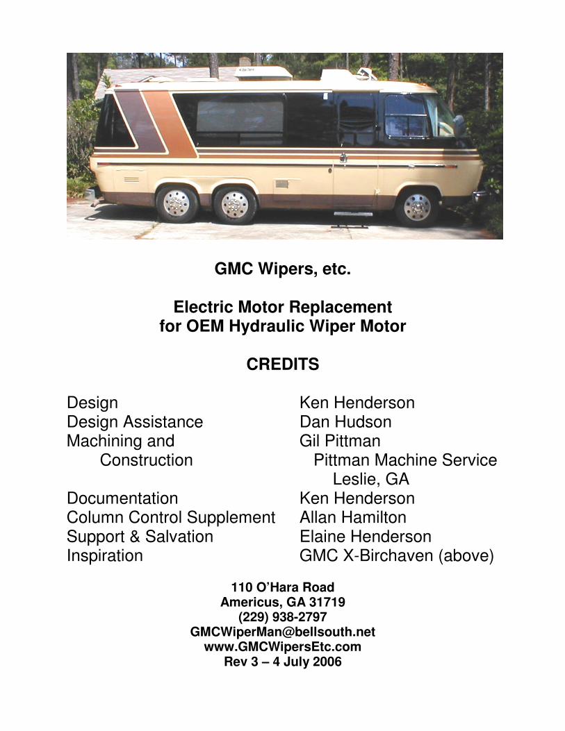
GMC Wipers, etc. Electric Motor Replacement for OEM Hydraulic Wiper Motor CREDITS Design Ken Henderson Design Assistance Dan Hudson Machining and Gil Pittman Construction Pittman Machine Service Leslie, GA Documentation Ken Henderson Column Control Supplement Allan Hamilton Support & Salvation Elaine Henderson Inspiration GMC X-Birchaven (above) 110 O’Hara Road Americus, GA 31719 (229) 938-2797 [email protected] www.GMCWipersEtc.com Rev 3 – 4 July 2006
Transcript of GMC Wipers, etc. Electric Motor Replacement for OEM Hydraulic
GMC Wipers, etc.
Electric Motor Replacement for OEM Hydraulic Wiper Motor
CREDITS
Design Ken Henderson Design Assistance Dan Hudson Machining and Gil Pittman Construction Pittman Machine Service Leslie, GA Documentation Ken Henderson Column Control Supplement Allan Hamilton Support & Salvation Elaine Henderson Inspiration GMC X-Birchaven (above)
110 O’Hara Road
Americus, GA 31719 (229) 938-2797
[email protected] www.GMCWipersEtc.com
Rev 3 – 4 July 2006

2
GMC Wipers, etc. Electric Wiper Conversion Kit
This is the installed electric motor conversion kit. Notice that the base plate is attached through the same bolt holes which held the hydraulic wiper motor in place. The pivot bolt for the Idler Arm Assembly is in the same position as the shaft of the hydraulic motor and the Linkage Arm (hidden at top) is the same length and configuration as that on the OEM motor, with one exception: the OEM driver and passenger wiper linkages were held to the linkage arm by latches; this design uses washers and cotter pins instead. The geometry of the Motor Arm, the Idler arm, and the Connecting link with the ball joint on each end makes the Linkage Arm move in exactly the same motion as did the motor arm on the hydraulic motor, with three exceptions: 1. Holes in the Idler Arm allow the wiper arm sweep to be set to one of three fixed arcs to allow for variations in assembly and wear between different coaches. 2. A slotted ball joint hole in the motor arm allows infinitely variable adjustment around the fixed sweeps established by those holes. 3. The length of the link between the ball joints can be changed to adjust the position of the wipers’ sweep arc, minimizing the need to move the wiper arms on their pivots.
3
The Lumina APV motor is shown with the motor housing extending to the driver’s side of the GMC (3 o’clock position). Late production mounting bases have 3 additional holes which allow the motor to be oriented to the 7 o’clock position.
GMC Motorhome
Electric Wiper Installation Instructions
These instructions are for the replacement of the GMC motorhome’s hydraulic windshield wiper motor with an electric motor. The modification consists of removing the hydraulic motor and rerouting the removed hydraulic lines. A custom mounting plate, linkage, and electric motor then replace the hydraulic motor. It is assumed that the wiper system is assembled with the wiper arms in the correct positions before beginning this conversion. BE SURE THE ARMS ARE IN THE DESIRED POSITION NOW.
PARTS REQUIRED
1. GMCWipersEtc’s Electric Wiper Kit which consists of electric motor mounting plate, linkage, and all associated hardware to replace the hydraulic motor with a customer-provided electric motor. 2. Customer provided electric windshield wiper motor. The following motors are known or expected to work:
A. 90-96 Chevrolet Lumina APV or Oldsmobile Silhouette or Pontiac TranSport mini-van -- This is the strongly recommended choice since the kit was designed specifically for it; any other motor may require modifications to the kit components. The motor assembly includes a control circuit for intermittent (delayed) wiping. A standard DPDT switch can be used to provide Lo and Hi speed operation; a 500k Ohm rheostat can be used to control intermittent wiping, if desired. These motors are available at most salvage yards for about $20. Rebuilt and new motors are available for around $70 from parts stores like AutoZone and www.rockauto.com. Be sure to get the electrical connector and as much wire as possible when harvesting your motor. DO get the metric nut to secure the motor arm to the shaft and the metric mounting screws. We offer complete wiring harnesses for use with this motor, but no other.
B. 2001 Saturn wiper motor (available from almost every surplus dealer in the country for <$20). The mating connector must be obtained from a donor vehicle or a dealer. This motor has been mounted but not run.
C. Almost any heavy duty (capable of swinging 2 each 24” wiper blades) continuously rotating windshield wiper motor. The operating shaft must be of the DIN splined type to fit the kit-provided Motor Arm (or a motor arm with a 5/16” hole at 1.37” from the center of the motor shaft must be supplied). Drilling of additional mounting holes may be necessary.
3. Customer provided wiper switch, washer switch, delay rheostat, wiring and
4
connectors as required for the chosen motor and operating functions. Instructions are attached to upgrade to a later model GM multi-function control switch for the turn signals, cruise control (not OEM), and windshield washer and wiper. We offer complete wiring harnesses with rocker, toggle, or push-to-wash/turn-to-wipe switches for use with the Lumina motor. 4. Some GMCs have the steel power steering return line routed to the top of the radiator, others to the bottom. Those routed to the top may require 3’ of power steering return hose. The use of fuel or other substitute hose is not recommended.
RECOMMENDED TOOLS 1. Fender cloth 2. Small flat blade screwdriver 3. Needle nose pliers 4. 8”-10” Adjustable (Crescent) wrench 5. Combination/Ratchet Wrenches: 7/16”, ½”, 5/8”, ¾”, 10 mm, & 13 mm 6. Water pump pliers to assist in installing OEM linkage to idler arm pins 7. Miscellaneous tools for installation of the chosen wiring and switch
HYDRAULIC MOTOR REMOVAL
1. There are three 5/16” cap screws inserted from the rear of the hydraulic motor mounting bracket. Use a ½” wrench to remove those and let the motor down until supported by the attached linkages. This is easier on ’73-‘76 models. 2. The hydraulic motor operating arm has a pin on its forward side to operate the passenger’s wiper and another on its aft side to operate the driver’s wiper. Connected link rods have sliding latches which engage grooves around the pins. The ends of those latches away from the pins are bent 90 degrees to form operating tabs. Grip each of the tabs with a pair of pliers and slide the latches away from the pins. Push the link rods off of the pins and let them lay where they fall; they’ll be re-attached to the electric motor assembly.
NOTE: If you prefer to skip the following steps until after the electric wiper installation is completed and tested, “just in case”, hang the hydraulic motor with a wire tie or other device from a convenient hard point, such as the brake line loops. Position the motor so the arm will not hit anything if it rotates – the control valve may not close completely with the cable disconnected. Jump to “Electrical Motor Installation”, following, and return to step 3. when you’re satisfied with the electric motor’s operation.
3. There are two hydraulic hoses attached to the hydraulic motor; that on the driver’s side supplies high pressure from the steering gear box; the other is the low pressure return line to the power steering pump. The high pressure hose will be removed with the motor. The low pressure return line will be re-routed to the steering gear box with the kit-provided Pipe Elbow, replacing the removed high pressure hose.
5
A. Loosen the set screw holding the control cable clamp to the hydraulic motor at its lower left; disconnect the control cable and position it out of the the way at the driver’s side. You can remove the control and cable from the dash at your leisure, or leave it for appearance.
B. Disconnect the return line from the hydraulic motor and insert the Pipe Elbow, securing it with the hose clamp. Route the return line down to the steering gear; you may have excess hose which can be cut off, or you may need to replace the hose with a longer one.
C. Disconnect the high pressure hose from the steering gear box and allow fluid to drain from the hose into a rag; there should not be much drainage. D. Connect the return line to the steering gear box and tighten the flare nut of the elbow securely. Fluid will now return directly to the power steering reservoir instead of flowing through the hydraulic wiper motor. NOTE: You may prefer to replace the two rubber and one steel return lines combination with a single rubber hose directly from the kit-provided elbow to the power steering reservoir.
E. Remove the hydraulic motor & high pressure line and store them for later resale at a GMC flea market; don’t throw it away because they’re irreplaceable. You can crank the engine now or later to check for leaks. F. This is a good time to clean and re-lubricate the wiper linkage pin holes with a good quality grease; white lithium or chassis grease is appropriate.
ELECTRIC MOTOR INSTALLATION
1. There are 3 each 5/16” holes in the kit-provided base plate to match those in the hydraulic motor. The pivot shaft and idler arms on the base plate must be toward the front of the coach – just try putting them on any other way! 2. Locate the passenger’s wiper link rod removed earlier and examine the latch assembly. For ease of manufacturing (=$Cost) we’ve chosen to use cotter pins to retain the link rods on the idler arm pins. You can either bend the end of the sheet metal latch away from the link rod to clear the cotter pin, or you can remove it completely. I recommend bending it in case someone wants to use it later – it’s not replaceable.
3. Place first the driver’s wiper link rod on the rear pin of the idler arm and then the passenger’s on the forward pin, securing them with a 3/8” flat washer on each side of the link rod, and cotter pins. The link rods will now support the base plate assembly. NOTE: Some installers have found it difficult to fit the link rods onto the pins; some have even resorted to drilling out the rod ends. DO NOT DO THAT. Any looseness in these fittings shows up as greatly amplified looseness in the wipers’ movement. Use a pair of water pump pliers to squeeze the rod ends onto the pins. They WILL fit.
6
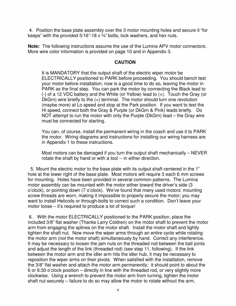
4. Position the base plate assembly over the 3 motor mounting holes and secure it “for keeps” with the provided 5/16”-18 x ¾” bolts, lock washers, and hex nuts.
Note: The following instructions assume the use of the Lumina APV motor connectors. More wire color information is provided on page 10 and in Appendix 3.
CAUTION
It is MANDATORY that the output shaft of the electric wiper motor be ELECTRICALLY positioned to PARK before proceeding. You should bench test your motor before installation; now is a good time to do so, leaving the motor in PARK as the final step. You can park the motor by connecting the Black lead to (-) of a 12 VDC battery and the White (or Yellow) lead to (+). Touch the Gray (or DkGrn) wire briefly to the (+) terminal. The motor should turn one revolution (maybe more) at Lo speed and stop at the Park position. If you want to test the Hi speed, connect both the Gray & Purple (or DkGrn & Pink) leads briefly. Do NOT attempt to run the motor with only the Purple (DkGrn) lead – the Gray wire must be connected for starting. You can, of course, install the permanent wiring in the coach and use it to PARK the motor. Wiring diagrams and instructions for installing our wiring harness are in Appendix 1 to these instructions. Most motors can be damaged if you turn the output shaft mechanically – NEVER rotate the shaft by hand or with a tool -- in either direction.
5. Mount the electric motor to the base plate with its output shaft centered in the 1” hole at the lower right of the base plate. Most motors will require 3 each 6 mm screws for mounting. Holes have been provided in several common patterns. The Lumina motor assembly can be mounted with the motor either toward the driver’s side (3 o’clock), or pointing down (7 o’clock). We’ve found that many used motors’ mounting screw threads are worn, making it impossible to properly secure the motor; you may want to install Helicoils or through-bolts to correct such a condition. Don’t leave your motor loose – it’s required to produce a lot of torque! 6. With the motor ELECTRICALLY positioned to the PARK position, place the included 3/8” flat washer (Thanks Larry Coldren) on the motor shaft to prevent the motor arm from engaging the splines on the motor shaft. Install the motor shaft and lightly tighten the shaft nut. Now move the wiper arms through an entire cycle while rotating the motor arm (not the motor shaft) simultaneously by hand. Correct any interference. It may be necessary to loosen the jam nuts on the threaded rod between the ball joints and adjust the length of the link (threaded rod) (see step 11, following). If the link between the motor arm and the idler arm hits the idler hub, it may be necessary to reposition the wiper arms on their pivots. When satisfied with the installation, remove the 3/8” flat washer and attach the motor arm permanently; it should point to about the 6 or 6:30 o’clock position – directly in line with the threaded rod, or very slightly more clockwise. Using a wrench to prevent the motor arm from turning, tighten the motor shaft nut securely – failure to do so may allow the motor to rotate without the arm,
7
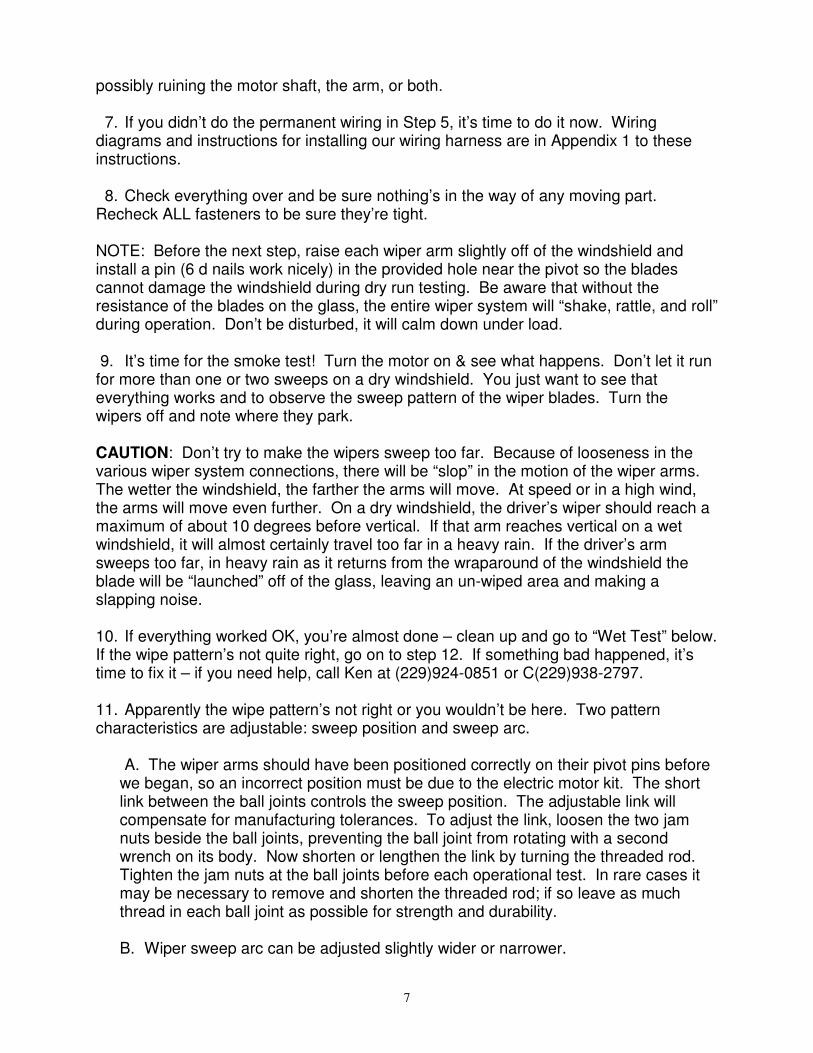
possibly ruining the motor shaft, the arm, or both.
7. If you didn’t do the permanent wiring in Step 5, it’s time to do it now. Wiring diagrams and instructions for installing our wiring harness are in Appendix 1 to these instructions.
8. Check everything over and be sure nothing’s in the way of any moving part. Recheck ALL fasteners to be sure they’re tight. NOTE: Before the next step, raise each wiper arm slightly off of the windshield and install a pin (6 d nails work nicely) in the provided hole near the pivot so the blades cannot damage the windshield during dry run testing. Be aware that without the resistance of the blades on the glass, the entire wiper system will “shake, rattle, and roll” during operation. Don’t be disturbed, it will calm down under load.
9. It’s time for the smoke test! Turn the motor on & see what happens. Don’t let it run for more than one or two sweeps on a dry windshield. You just want to see that everything works and to observe the sweep pattern of the wiper blades. Turn the wipers off and note where they park. CAUTION: Don’t try to make the wipers sweep too far. Because of looseness in the various wiper system connections, there will be “slop” in the motion of the wiper arms. The wetter the windshield, the farther the arms will move. At speed or in a high wind, the arms will move even further. On a dry windshield, the driver’s wiper should reach a maximum of about 10 degrees before vertical. If that arm reaches vertical on a wet windshield, it will almost certainly travel too far in a heavy rain. If the driver’s arm sweeps too far, in heavy rain as it returns from the wraparound of the windshield the blade will be “launched” off of the glass, leaving an un-wiped area and making a slapping noise.
10. If everything worked OK, you’re almost done – clean up and go to “Wet Test” below. If the wipe pattern’s not quite right, go on to step 12. If something bad happened, it’s time to fix it – if you need help, call Ken at (229)924-0851 or C(229)938-2797.
11. Apparently the wipe pattern’s not right or you wouldn’t be here. Two pattern characteristics are adjustable: sweep position and sweep arc.
A. The wiper arms should have been positioned correctly on their pivot pins before we began, so an incorrect position must be due to the electric motor kit. The short link between the ball joints controls the sweep position. The adjustable link will compensate for manufacturing tolerances. To adjust the link, loosen the two jam nuts beside the ball joints, preventing the ball joint from rotating with a second wrench on its body. Now shorten or lengthen the link by turning the threaded rod. Tighten the jam nuts at the ball joints before each operational test. In rare cases it may be necessary to remove and shorten the threaded rod; if so leave as much thread in each ball joint as possible for strength and durability.
B. Wiper sweep arc can be adjusted slightly wider or narrower.
8
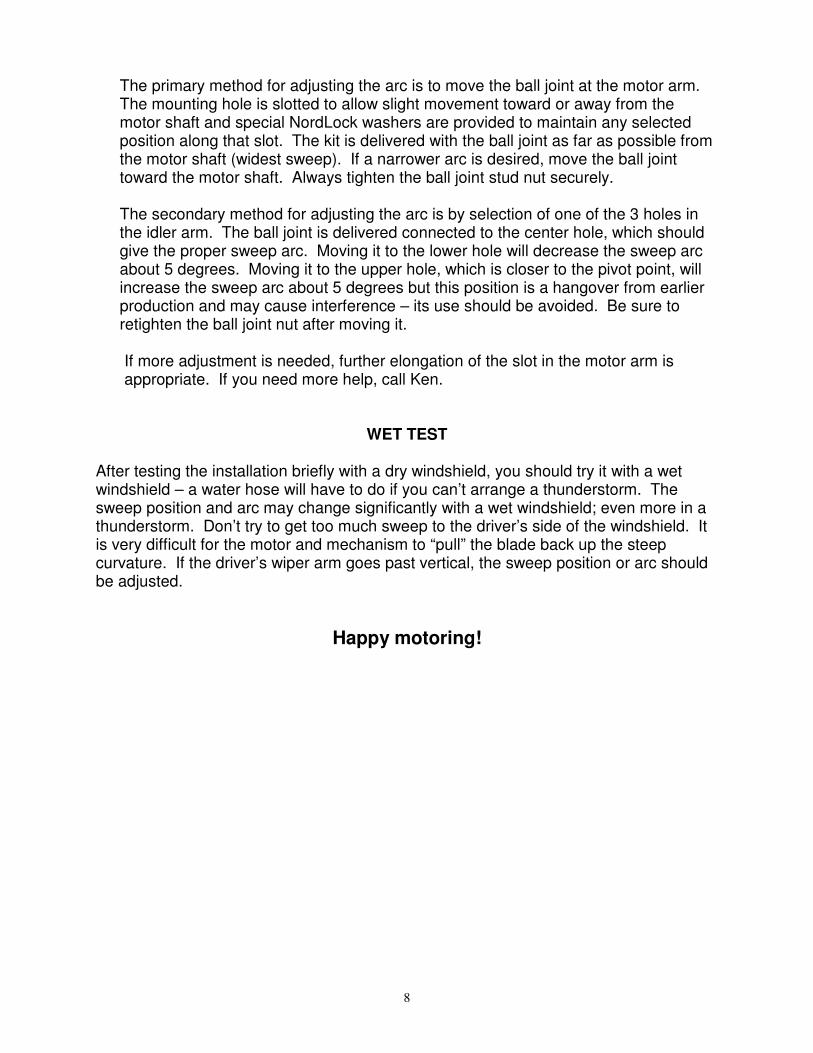
The primary method for adjusting the arc is to move the ball joint at the motor arm. The mounting hole is slotted to allow slight movement toward or away from the motor shaft and special NordLock washers are provided to maintain any selected position along that slot. The kit is delivered with the ball joint as far as possible from the motor shaft (widest sweep). If a narrower arc is desired, move the ball joint toward the motor shaft. Always tighten the ball joint stud nut securely.
The secondary method for adjusting the arc is by selection of one of the 3 holes in the idler arm. The ball joint is delivered connected to the center hole, which should give the proper sweep arc. Moving it to the lower hole will decrease the sweep arc about 5 degrees. Moving it to the upper hole, which is closer to the pivot point, will increase the sweep arc about 5 degrees but this position is a hangover from earlier production and may cause interference – its use should be avoided. Be sure to retighten the ball joint nut after moving it.
If more adjustment is needed, further elongation of the slot in the motor arm is appropriate. If you need more help, call Ken.
WET TEST
After testing the installation briefly with a dry windshield, you should try it with a wet windshield – a water hose will have to do if you can’t arrange a thunderstorm. The sweep position and arc may change significantly with a wet windshield; even more in a thunderstorm. Don’t try to get too much sweep to the driver’s side of the windshield. It is very difficult for the motor and mechanism to “pull” the blade back up the steep curvature. If the driver’s wiper arm goes past vertical, the sweep position or arc should be adjusted.
Happy motoring!
9
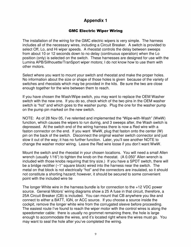
Appendix 1
GMC Electric Wiper Wiring
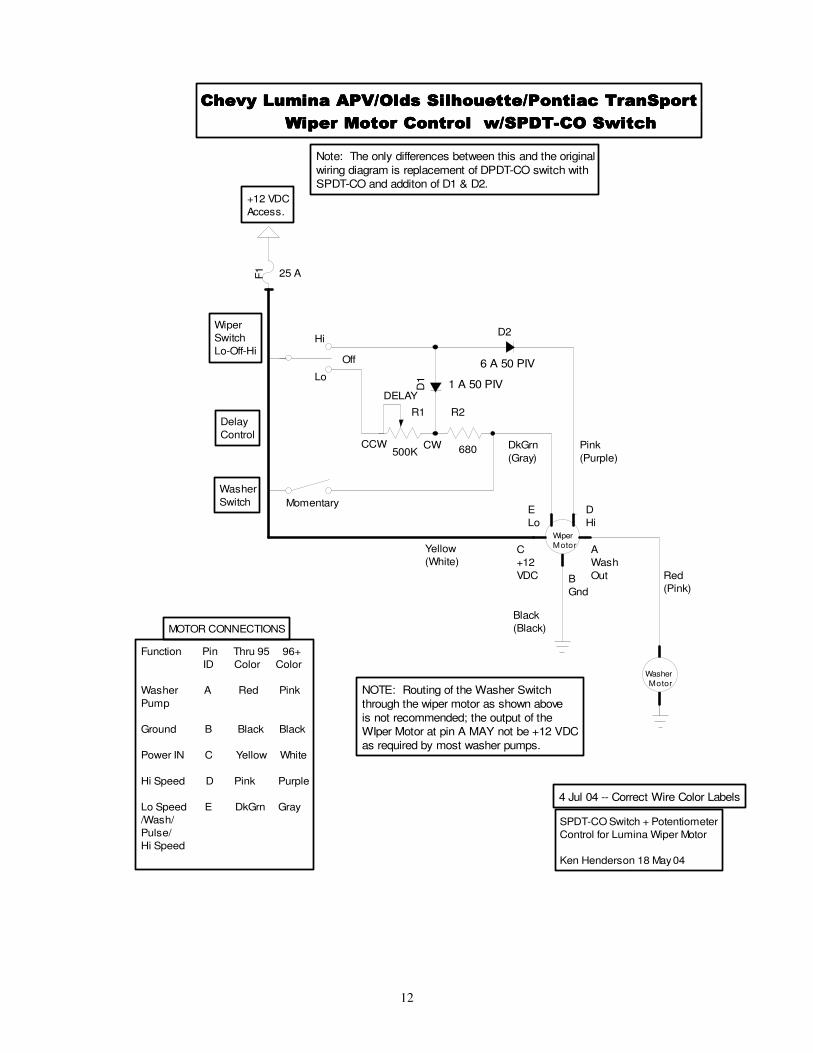
The installation of the wiring for the GMC electric wipers is very simple. The harness includes all of the necessary wires, including a Circuit Breaker. A switch is provided to select Off, Lo, and Hi wiper speeds. A rheostat controls the delay between sweeps from about 10 or 12 seconds down to no delay (continuous operation) when the Lo position (only) is selected on the switch. These harnesses are designed for use with the Lumina APB/Sillhouette/TranSport wiper motors; I do not know how to use them with other motors. Select where you want to mount your switch and rheostat and make the proper holes. No information about the size or shape of those holes is given because of the variety of switches and rheostats which may be provided in the kits. Be sure the two are close enough together for the wire between them to reach. If you have chosen the Wash/Wipe switch, you may want to replace the OEM Washer switch with the new one. If you do so, check which of the two pins in the OEM washer switch is “hot” and which goes to the washer pump. Plug the one for the washer pump on the pump pin marked on the new switch. NOTE: As of 28 Nov 05, I’ve relented and implemented the “Wipe-with-Wash” (WwW) function, which causes the wipers to run during, and 3 sweeps after, the Wash switch is depressed. At the switch end of the wiring harness there is now a Red wire with a faston connector on the end. If you want WwW, plug that faston onto the center (W) pin on the back of the switch. Disconnect the original washer switch connector and just stow it out of the way; it has no further function. Later, you’ll see another NOTE to change the washer motor wiring. Leave the Red wire loose if you don’t want WwW. Mount the switch and the rheostat in your chosen locations. You will need a small Allen wrench (usually 1/16”) to tighten the knob on the rheostat. (A 0.050” Allen wrench is included with those knobs requiring that tiny size.) If you have a SPDT switch, there will be a bridge rectifier (~1” square block) wired into the harness near the switch. The metal on that block is not electrically “hot” and the connectors are insulated, so it should not constitute a shorting hazard; however, it should be secured to some convenient point with the included wire tie The longer White wire in the harness bundle is for connection to the +12 VDC power source. General Motors’ wiring diagrams show a 25 A fuse in that circuit, therefore, a 25A Circuit Breaker (CB) is included. You can mount that CB anywhere you like and connect to either a BATT, IGN, or ACC source. If you choose a source inside the cockpit, remove the longer white wire from the corrugated sleeve before proceeding. The easiest route I’ve found to reach the wiper motor with the control wires is along the speedometer cable: there is usually no grommet remaining there, the hole is large enough to accommodate the wires, and it’s located right where the wires must go. You may want to seal the hole after you’ve completed the wiring.
10
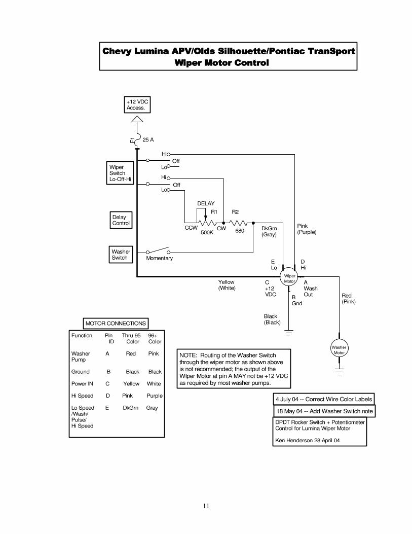
Connect the shorter White wire to the White (or Yellow) wire from the wiper motor using the provided butt connector. The use of a crimping tool is strongly recommended, but a pair of lock grip pliers can be used to compress the connector. NOTE: The color coding included here is that for the early and late Lumina motor connectors. Connectors from other vehicles are sometimes used and may have other color codes. Some other combinations and the connector pinouts are detailed in Appendix 3; refer to it if any of this is confusing. The Violet harness wire should connect to the Purple (or Dark Green) motor wire and the Gray should join the Gray from the motor. Connect the Black wire from the motor to ground. The unused Pink motor wire would be connected to the washer pump if you connected it for automatic operation; I do not recommend that modification; bundle the wire and tie it off, or remove it. NOTE: If you’ve connected the Red wire to the switch to implement WwW, you must connect the unused Pink motor wire to the power (+12 VDC) side of the washer pump, disconnecting the original wire. This wire will now be Hot, to operate the washer pump, while the Wash switch is depressed and the wiper will run for 3 sweeps after it is released. Finally, connect the longer White wire to the CB, using the provided ring terminal, after you’ve determined the proper location for the CB, mounted it, and cut the wire to an appropriate length. While it will allow the wipers to run with the ignition OFF, the main Chassis Battery junction on the passenger firewall is a good solid source of +12 VDC. With the CB connected to +12 VDC, your wipers should operate as expected: With the switch in the Lo position, the setting of the Rheostat should determine the delay between wiper sweeps. With Hi selected, there will be no delay. . Enjoy. If you have problems or questions, send me an email, or call me.
====== *** ====== NOTE: Here’s a simple way to incorporate ignition switch control while connecting the 25A CB to the easily accessible “Chassis Battery” bolt on the passenger’s firewall: Use the Yellow power lead from the windshield washer switch to control a 30A automotive “ice cube” relay inserted in the White wire to the CB. This feature has not been illustrated in the wiring diagram to prevent overly complicating it.
REFER TO APPENDIX 3 FOR ADDITIONAL WIRE COLOR INFORMATION.
11
25 A
680500K
Hi
Lo
Off
DELAY
CWCCW
MOTOR CONNECTIONS
DelayControl
WasherSwitch Momentary
WiperSwitchLo-Off-Hi
Red(Pink)
Yellow(White)
Pink(Purple)
Black(Black)
DkGrn(Gray)
+12 VDCAccess.
Function Pin Thru 95 96+ ID Color Color
Washer A Red PinkPump
Ground B Black Black
Power IN C Yellow White
Hi Speed D Pink Purple
Lo Speed E DkGrn Gray/Wash/ Pulse/Hi Speed
Hi
Lo
Off
Chevy Lumina APV/Olds Silhouette/Pontiac TranSportChevy Lumina APV/Olds Silhouette/Pontiac TranSportChevy Lumina APV/Olds Silhouette/Pontiac TranSportChevy Lumina APV/Olds Silhouette/Pontiac TranSport
Wiper Motor Control Wiper Motor Control Wiper Motor Control Wiper Motor Control
NOTE: Routing of the Washer Switchthrough the wiper motor as shown above is not recommended; the output of the WIper Motor at pin A MAY not be +12 VDCas required by most washer pumps.
18 May 04 -- Add Washer Switch note
4 July 04 -- Correct Wire Color Labels
DPDT Rocker Switch + PotentiometerControl for Lumina Wiper Motor
Ken Henderson 28 April 04
F1
R1 R2
Wiper
Motor
ELo
DHi
AWashOut
C+12VDC
BGnd
Washer
Motor
12
25 A
680500K
Lo
DELAY
CWCCW
MOTOR CONNECTIONS
Delay
Control
Washer
Switch Momentary
Wiper
Switch
Lo-Off-Hi
Red
(Pink)
Yellow
(White)
Pink
(Purple)
Black
(Black)
DkGrn
(Gray)
+12 VDC
Access.
Function Pin Thru 95 96+
ID Color Color
Washer A Red Pink
Pump
Ground B Black Black
Power IN C Yellow White
Hi Speed D Pink Purple
Lo Speed E DkGrn Gray
/Wash/
Pulse/
Hi Speed
Hi
Off
1 A 50 PIV
6 A 50 PIV
Chevy Lumina APV/Olds Silhouette/Pontiac TranSportChevy Lumina APV/Olds Silhouette/Pontiac TranSportChevy Lumina APV/Olds Silhouette/Pontiac TranSportChevy Lumina APV/Olds Silhouette/Pontiac TranSport
Wiper Motor Control w/SPDT-CO Switch Wiper Motor Control w/SPDT-CO Switch Wiper Motor Control w/SPDT-CO Switch Wiper Motor Control w/SPDT-CO Switch
Note: The only differences between this and the original
wiring diagram is replacement of DPDT-CO switch with SPDT-CO and additon of D1 & D2.
NOTE: Routing of the Washer Switch
through the wiper motor as shown above
is not recommended; the output of the WIper Motor at pin A MAY not be +12 VDC
as required by most washer pumps.
4 Jul 04 -- Correct Wire Color Labels
SPDT-CO Switch + Potentiometer
Control for Lumina Wiper Motor
Ken Henderson 18 May 04
F1
R1 R2
WiperMotor
E
Lo
D
Hi
A
Wash
Out
C
+12
VDC B
Gnd
Washer Motor
D1
D2
13
14
APPENDIX 2
LUBRICATION The idler arm has oil-impregnated sintered bronze bushings which should never need lubrication. But “just in case” we have installed a grease fitting on the hub and filled it with molybdenum disulfide grease. The ball joints are sealed so require no lubrication. The OEM linkage should have a little 30 weight oil applied occasionally.
REPLACEMENT PARTS
In the unlikely event replacement parts are required, McMaster-Carr (www.mcmaster.com) can supply the following items: Light Duty Ball Joint Linkage Shielded, 5/16"-24 Stud/Shank Thread Size Part No. 6058K42 -- 2 each required SAE 841 Bronze Flanged Bearing For 1/2" Shaft Diameter, 5/8" OD, 3/4" Length Part No. 6338K419 – 2 each required Except for the custom base plate and idler arm, all other parts are common hardware items which should be readily available locally, or from McMaster-Carr.
15
Appendix 3
’90-’96 Lumina APV/Silhouette/TranSport Wiper Arm and Motor Removal
These wiper motors are strong enough to swing the long GMC motor home arms and blades – or their own adapted to GMCs. They also come with an internal control circuit for pulse (intermittent) operation. Here are the instructions for removing them; there is a picture of the motor, arm, and the tools necessary to remove them at http://gmcmhphotos.com/gallery/showpic.php?aid=479&uuid=kenhenders&pid=4935. If you just want 2 left arms for your coach, you might as well go ahead and get the motors from both vehicles; you can sell or barter them to someone who wants to do the electric motor conversion. 1. On each wiper arm, pry off the plastic decorative cap over the retaining nut and remove the nut with a 15 mm wrench. 2. Remove the washer hoses where they attach to the fitting on the cowling. 3. Remove the arms with a small gear puller – or (not recommended) a large screwdriver under the arm and a hammer on the exposed stud – all the surrounding structure is plastic and offers no purchase. Save the left arm and leave the right one. 4. Raise the hood and remove the air cleaner from the engine. You’ll have to remove its top cover, then take out the retaining stud before you can get the lower housing out. 5. Don’t fail to get the electrical connector for the motor; a new one costs $25+. Trace the wire from the motor, under the passenger side cowling, down toward the center of the firewall, and possibly over to the driver’s side, as far as you can, then cut it. Pull the wires free of any retaining clips until it hangs free beneath the motor. 6. Examine the motor’s mounting and remove the three mounting screws with a 10 mm wrench. On some vehicles, there is a slot in the mounting bracket that will allow the motor to be slid sideways and removed. On others, one must remove the entire wiper system from the body. If the motor will come out without removing everything, skip to step 11, following. Keep the 3 each 6 X 1.0 mm screws 7. The wiper system is held in place by a large knurled nut just outboard of each of the wiper arm shafts and by 3 each 11 mm nuts on studs. The knurled nuts will have to be broken loose with either a #55 torx driver or a 5/16 Allen wrench. 8. Two of the 11 mm nuts are located in the center of the cowling above the engine fore and aft of the tubular frame. Most of those I’ve removed have not had the rear nut installed. 9. The 3rd 11 mm nut is on the passenger side aft of the wiper motor. 10. With those 5 retainers removed, the entire tubular frame will come out – somehow.

16
11. It is not necessary, or recommended, to remove the arm from the wiper motor at this time. If you do, keep the nut! 12. The wiper linkage must be released from the ball joint on the wiper motor arm with a 7 mm socket.
------------------------------------------------------------------------------------------------------------ The motor connector will have five wires coming from it. Dependent upon the year of the vehicle the colors may be one of the following combinations: LATCH
A. Washer Pump (A) (C) At left are the pin B. Ground labels for the connector, C. Power (+12 VDC) (B) looking into the wire D. High Speed side. Use those labels E. Low Speed (D) (E) to determine the correct
wire connection
Color Codes Following are the known wire colors found on the Lumina APV-type connectors.
Kit Color Pin 90-95 Lumina 96 Lumina Unknown Unknown ------------ ---- ------------------- -------------- ------------ ------------ Not used A Red Pink Green Orange Ground Note: The provided instructions assume the use of one of the Lumina APV motor connectors. B Black Black Black Black White C Yellow White Yellow White Violet D Pink Violet Violet Blue Gray E Green Gray Gray Gray
(Note: The GM “violet” could be considered “purple”)
Substitute your wire colors for the codes (X) in the following instructions.
13. To test the motor, strip about ½” of insulation from the ends of the (B), (C), (D), and (E) wires. Twist the (C) (always hot) and (E)(low speed) wires together. Holding the motor clear of the rotating arm, connect the Black (B) (ground) wire to (-) and the (C)&(E) pair to +12VDC,. It should run in low speed.
Now add the (D)(high speed) wire to the (C)&(E) pair. NEVER connect the (D) to power without the (E)! The motor should run at high speed. If you want to test the pulse circuit, connect Black(B)(-) and (C)(+12VDC), then place 30k - 300k Ohms between (E)(low speed) and (C)+12VDC; the larger the resistance, the longer the sweep delay.

17
14. The going price for a functional motor is about $20-$25. A new one is $90 to $180; a rebuilt one about $70 + $10 core. If the pulse board is bad, it’s about $28 for a rebuilt replacement board. NOTE: The most common failure of these motors is very easily repaired: Remove the black plastic cover over the printed circuit board. With a small screwdriver, pry gently all around the board until it is unplugged from its connectors and can be removed. With a hot soldering iron, remelt the solder at each of the five (5) solder joints attaching the external connector to the printed circuit board. That will repair most problems. Clean the sping-loaded contacts, reassemble the motor, and test as described above.
18
Appendix 4
GMC Motorhome Electric Wiper Installation Instruction
Steering Column Controls by Al Hamilton 23 April 2004
This portion of the Instruction covers the installation of a switch and associated parts to control the electric wipers and windshield washer from a multi-function turn signal lever mounted on the steering column. The functioning and control would be the same as on most GM cars and trucks in the 1990s. The “new” turn signal lever allows for control of the electric wipers, windshield washer, cruise control, and turn signals on the steering column. The cruise control switch will only operate an electronic cruise control. In the main portion of this Instruction, a switch and rheostat is included which will operate the electric wipers and makes no changes to the GMC turn signal lever or the original-transducer style cruise control.
PARTS REQUIRED 1. The three main parts needed for this installation are: a. a multi-function turn signal lever - with “mist”, “off”, “delay”, “low”, & “high” positions for the wiper/washer control and “off”, “on”, & “resume” for the cruise control. These levers have four small wires in red, yellow, green, & blue. These four wires become pink, grey, dark blue, & black a few inches from the lever. Be sure to take some of the second set of wires because it is on these that after market electronic cruise control instructions are based; b. a pulse wiper/washer switch – this is the switch mounted in the steering column that the turn signal lever plugs into. One is needed with three wires in white, grey, & purple and “delay” written on the turn signal lever; and, c. the top steering column housing that covers the wiper/washer switch and the ignition key cylinder.
SPECIAL TOOLS In addition to the normal tools for such a job as this, some special ones are required: a. steering wheel remover; b. spring compressor (more later on the need for this); and, c. Torx screwdriver # T-27.
19
DONOR VEHICLES 3. There are many GM cars and trucks in the salvage yards with the parts listed above that will fit and work. You can even search for the colour of your choice and the amount of chrome you want on the turn signal lever. Not all vehicles could be listed here. It was found that the 1990 to 1995 GM Astra and Safari vans with pulse (delay) wipers are plentiful and have two of the three parts needed – the wiper/washer switch and the top steering column housing. The multi-function lever can come from these vans or a car or truck. To find one that still has good lettering is the trick.
PARTS REMOVAL 4. Remove the steering wheel and set aside. Remove the circular plastic cover on the steering column – should just pull off – save in case you damage the one on your coach. Next is a circular clip just below the threaded portion of the steering shaft. The circular steel plate on top of the steering column has to be pushed down against a spring to get the clip out. That’s what the spring compressor is for. With a bit of muscle and a large screwdriver the spring can be compressed and the clip pried out. It’s not easy!!! 5. Remove three Phillips screws that hold the turn signal mechanism in place. Remove the 10mm bolt that attaches the piece that is moved by the lever. It is at the 10 o’clock position. Save that piece. Now pull up on the turn signal mechanism and cut the wires to remove it or disconnect it at the lower end of the steering column and pull the wires all the way out of the column – not always easy. 6. Remove the ignition cylinder by pressing on the tab that the holds it in place. Remove the emergency flashers switch with a Phillips screwdriver. Remove the tilt column lever by turning it out. The “key reminder” contacts are like two copper rabbit ears and hopefully they remained in place. It is best to leave them and use them in your coach. They are a bit difficult to get back in their little square hole. Remove the turn signal lever by pulling straight out on it. 7. In front of you now are three Torx bolts. Remove them and the steering column housing, with the wiper/washer switch still in place, should come off. Cut the three wires to the switch, saving as much wire as possible. 8. Find and remove, by pulling out and cutting the wires (see para 1a above), the best turn signal lever you can, if the one in the vehicle you are working on is not suitable.
DISASSEMBLY OF YOUR GMC COLUMN 9. Remove the steering wheel, plastic cover, steel circular plate and clip, and turn signal lever by turning it out if original. Disconnect the cruise control wires and pull up through the steering column. Turn out and remove the tilt column lever. Remove
20
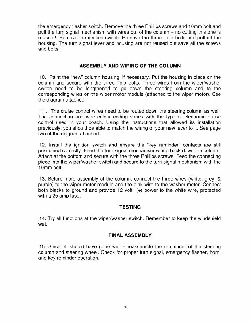
the emergency flasher switch. Remove the three Phillips screws and 10mm bolt and pull the turn signal mechanism with wires out of the column – no cutting this one is reused!!! Remove the ignition switch. Remove the three Torx bolts and pull off the housing. The turn signal lever and housing are not reused but save all the screws and bolts.
ASSEMBLY AND WIRING OF THE COLUMN 10. Paint the “new” column housing, if necessary. Put the housing in place on the column and secure with the three Torx bolts. Three wires from the wiper/washer switch need to be lengthened to go down the steering column and to the corresponding wires on the wiper motor module (attached to the wiper motor). See the diagram attached. 11. The cruise control wires need to be routed down the steering column as well. The connection and wire colour coding varies with the type of electronic cruise control used in your coach. Using the instructions that allowed its installation previously, you should be able to match the wiring of your new lever to it. See page two of the diagram attached. 12. Install the ignition switch and ensure the “key reminder” contacts are still positioned correctly. Feed the turn signal mechanism wiring back down the column. Attach at the bottom and secure with the three Phillips screws. Feed the connecting piece into the wiper/washer switch and secure to the turn signal mechanism with the 10mm bolt. 13. Before more assembly of the column, connect the three wires (white, grey, & purple) to the wiper motor module and the pink wire to the washer motor. Connect both blacks to ground and provide 12 volt (+) power to the white wire, protected with a 25 amp fuse.
TESTING 14. Try all functions at the wiper/washer switch. Remember to keep the windshield wet.
FINAL ASSEMBLY 15. Since all should have gone well – reassemble the remainder of the steering column and steering wheel. Check for proper turn signal, emergency flasher, horn, and key reminder operation.

21
PULSE WIPER/WASHER WIRING DIAGRAM for GMC ELECTRIC WINDSHIELD WIPERS
(1990-97 GM Lumina/Silhouette/Transport SE wiper motor & GM Astra/Safari van multi-function switch, turn signal lever, & steering column housing is suggested to
complete the installation) (See Note 1)
Turn Signal Lever
Multi-function Cruise Control / Turn Signals
Switch
White (See Note 2) (+) 25 Amp Fuse Grey Purple White Wiper Motor Black Pink Notes: 1 – Internal GMC steering column wiring can still be used. 2 – Washer & switch wire colours vary by year. Pre-1995 shown above. Both will work. See diagram below. 3 – Cruise Control wires colours vary by type. See Page 2 for suggestions
Wiper Motor Wiring Variations
Pre-1995 1995 & On White Yellow Grey Dark Green Purple Pink Pink Red Black Black
Wiper
Motor
Washer
Motor
22
GMC ELECTRIC WIPER – PAGE 2 CRUISE CONTROL WIRING DIAGRAM
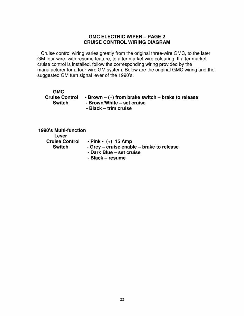
Cruise control wiring varies greatly from the original three-wire GMC, to the later GM four-wire, with resume feature, to after market wire colouring. If after market cruise control is installed, follow the corresponding wiring provided by the manufacturer for a four-wire GM system. Below are the original GMC wiring and the suggested GM turn signal lever of the 1990’s. GMC Cruise Control - Brown – (+) from brake switch – brake to release Switch - Brown/White – set cruise - Black – trim cruise 1990’s Multi-function Lever Cruise Control - Pink - (+) 15 Amp Switch - Grey – cruise enable – brake to release - Dark Blue – set cruise - Black – resume