GMAW Weld Design Guideline - steel.org/media/Files/ASP/Enabling Programs/ASP... · Final Project...
17
GMAW Weld Design Guidelines for Chassis Structures
Transcript of GMAW Weld Design Guideline - steel.org/media/Files/ASP/Enabling Programs/ASP... · Final Project...

GMAW Weld Design Guidelines for Chassis Structures - 1 -
GMAW Weld Design Guidelines
for Chassis Structures

GMAW Weld Design Guidelines for Chassis Structures
Final Project Report November 2007
Prepared by Chonghua (Cindy) Jiang
Justin Hunt Yan (Jack) Sang
AET Integration, Inc Tel: 248-668-3891
GMAW Weld Design Guidelines for Chassis Structures - 2 -

TABLE OF CONTENTS 1. General 1.1 Scope ............................................................................................................................................... 1 1.2 Purpose............................................................................................................................................ 1 1.3 Definitions ....................................................................................................................................... 1 1.4 Normative References .................................................................................................................... 1 2. Gas Metal Arc Welding (GMAW) Process
2.1 GMAW Process ................................................................................................................................ 2 2.2 GMAW Process Limitations for Chassis Structures....................................................................... 2 2.3 Welding Position.............................................................................................................................. 2
3. Product Design Requirements for GMAW Chassis Structures.................................................................... 3
4. Material 4.1 Steel Thickness and Combination Limitations .............................................................................. 3 4.2 Steel Chemistry Limitations............................................................................................................ 4 4.3 Material Coatings ............................................................................................................................ 4 4.4 Filler Metal Limitations ................................................................................................................... 4
4.4.1 Type ................................................................................................................................... 4 4.4.2 Diameter............................................................................................................................ 4
5. Weld Design
5.1 Application of Weld Joint Design Requirements ........................................................................... 4 5.1.1 Joint Type........................................................................................................................... 4 5.1.2 Weld Joint Design Tolerance ............................................................................................ 5 5.1.3 Maximum Allowable Gap (Part fit-up) .............................................................................. 6 5.1.4 Parts Tolerance for Joint Repeatability............................................................................ 7
5.2 Weld Types ...................................................................................................................................... 7 5.2.1 Fillet Weld.......................................................................................................................... 7
5.2.1.1 Required Weld Joint Overlap....................................................................... 7 5.2.2 Slot Weld ........................................................................................................................... 8 5.2.3 Flare Bevel Groove and Flare V Weld .............................................................................. 9
5.2.3.1 Applicable Joint Types ................................................................................. 9 5.2.3.2 Weld Joint Radius Requirement ................................................................. 9
5.3 Weld Size (Refer to AWS D8.8M:2007) ....................................................................................... 10 5.4 Weld Quality (Refer to AWS D8.8M:2007)................................................................................... 10 5.5 Product Design Considerations.................................................................................................... 10
5.5.1 Welding Accessibility....................................................................................................... 10 5.5.2 Joint Location Repeatability ........................................................................................... 10 5.5.3 Weld Design for Reduced Stress Concentration........................................................... 11
5.5.3.1 Weld Line Design....................................................................................... 12 5.5.3.2 Location of Weld Overlap .......................................................................... 12 5.5.3.3 Location of Tack Weld............................................................................... 12 5.5.3.4 Minimum Distance between Weld Line and Radius Tangent................. 12
5.5.4 Intermittent Welding....................................................................................................... 13 5.5.5 Slip Plane Configuration ................................................................................................. 14
GMAW Weld Design Guidelines for Chassis Structures - 3 -

1. General 1.1 Scope
This document establishes the design guidelines for gas metal arc welded chassis structures, with a minimum thickness of 2.0 mm, including products that employ both conventional steel and advanced high-strength steels. This guideline is based on comparison and evaluation of existing OEM arc weld design standards and identification of design rules that would be applicable to future A/SP Lightweighting Projects.
1.2 Purpose
The purpose of this guideline is to support the A/SP Lightweight Chassis Structure Team in welding of advanced high-strength steels (AHSS) and future A/SP Projects.
1.3 Definitions
Please refer to the ANSI/AWS A3.0, Standard Welding Terms and Definitions, for definitions of welding terms used in this guideline.
ANSI: American National Standards Institute AWS: American Welding Society Base Metal: The metal components that form the weld joint. This standard typically identifies base metals as T1 and T2 when referring to the materials thickness. Free Machining Steel: Particular grades of steel that have small amounts of additional alloying elements to improve machinability. Common additives are sulfur and lead in steel and sulfur or selenium in stainless steel. Gap: Any separation at the joint root between the work pieces is called a root opening. For the purpose of this standard, this opening will be called a gap. Sheet: Refers to the base metal being welded. The top sheet is always closest to the weld gun, and the bottom sheet is always the farthest from the weld gun. Weld Length: Weld length defined here is the portion of the weld that meets all of the design requirements.
1.4 Normative References
The following normative references contain provisions that, through reference in this text, constitute provisions of this guideline. All normative documents are subject to revision and the most recent editions of the normative standards indicated below shall apply. Users of this standard must be familiar with and keep apprised of changes to the information contained in these documents. ANSI/AWS A3.0, Standard Welding Terms and Definitions. ANSI/AWS A5.18/A5.18M, Specification for Carbon Steel Electrodes and Rods for Gas Shielded Arc Welding.
GMAW Weld Design Guidelines for Chassis Structures - 1 -

2. Gas Metal Arc Welding (GMAW) Process 2.1 GMAW Process
Additional information regarding gas metal arc welding can be found in the AWS Welding Handbook, Eighth Edition, Volume 2, Chapter 4, Gas Metal Arc Welding.
2.2 GMAW Process Limitations for Chassis Structure
Gas metal arc welding closer than 25 mm to surfaces or edges coated with sealer or adhesives is not recommended. The minimum specified weld length should be 13 mm or greater. Excessively large weld size, which results from more than one pass of welds, is not recommended.
2.3 Welding Position
Basic welding positions are shown in Figure 2-1. It is recommended that all welding joints be positioned for welding in either the flat or horizontal position whenever possible. The horizontal or vertical plane of the flat and horizontal joint may vary up to a maximum of 10 degrees.
Sheet Vertical Sheet HorizontalSheet HorizontalSheet 45º to Vertical Plane
Axis of WeldHorizontalAxis of Weld
VerticalAxis of Weld
HorizontalAxis of Weld
Horizontal
Sheet Vertical Sheet HorizontalSheet HorizontalSheet 45º to Vertical Plane
Axis of WeldHorizontalAxis of Weld
VerticalAxis of Weld
HorizontalAxis of Weld
Horizontal
Figure 2-1: Basic Welding Positions
GMAW Weld Design Guidelines for Chassis Structures - 2 -

3. Engineering Releases for GMAW Chassis Structures
Engineering releases should specify the following: 1. Material type, material coating and material thickness 2. Weld type 3. Weld size 4. Weld length The weld quality should be consistent with AWS D8.8M:2007, Specification for Automotive Weld Quality-Arc Welding of Steel.
4. Material
This guideline applies only to steels, regardless whether it is conventional or advanced high-strength steels (AHSS), as shown in Table 4-1. Table 4-1: IISI Steel Classification
Group Minimum Tensile Strength Typical Products
1 <350 MPa
Mild 140/270 BH 180/300 BH 210/320 BH 240/340
2 350-500 MPa
BH 260/370 HSLA 280/350 HSLA 350/450
DP 300/500
3 >500-800 MPa
DP 350/600 TRIP 350/600 DP 500/800
TRIP 500/800 CP 700/800
4 >800 MPa
DP700/1000 MS 950/1200
MS 1150/1400 MS 1250/1520 HF 950/1300
4.1 Recommended Steel Thickness and Combination Limitations
Both the steel thickness and thickness combinations specified by product design are limited by the capability of the arc welding process. The recommended steel thickness limits and maximum combinations ratio for GMAW process are shown in Table 4-2. For a lap joint, it is recommended that the thinner steel be on the top. Three-thickness joint design is not recommended.
GMAW Weld Design Guidelines for Chassis Structures - 3 -

Table 4-2: Recommended Steel Thickness and Combination Ratio Limits
Minimum Thickness* Maximum Thickness Maximum Combination Ratio
2.0 mm 9.0 mm 3:1 *Use of sheet thickness less than 2.0 mm may be specified in AHSS, but may require corrosion protection.
4.2 Steel Chemistry Limitations
Certain chemical elements may have detrimental effects on the weldability of steels. Table 4-3 can be used as a reference for designers to choose steels. It is preferred to keep both sulfur and phosphorous content under 0.035 wt.% each. No free machining steels are allowed for chassis structures when GMAW is the welding process.
Table 4-3: Steel Chemistry Limitations (Wt.%)
Sulfur (S) Content
Phosphorous (P) Content
Boron (B) Content
≤0.05% ≤0.06% ≤0.005%
4.3 Filler Metal Selections 4.3.1 Type
AWS A5.18 solid welding wires ER70S-6 and ER70S-3 are recommended for chassis structures. AWS solid wire ER80S-D2 may also be used if a higher strength weld metal is needed. Engineering judgment is needed to select the filler metal type for specific applications.
4.3.2 Diameter
The recommended filler metal diameter is 1.14 mm (0.045”). Other wire diameters, such as 0.89 mm (0.035”) and 1.32 mm (0.052”), may also be used depending on the specific application.
5. Weld Design
The weld joint and weld type combinations available to the designer are limited to those identified in this guideline.
5.1 Application of Weld Joint Design Requirements 5.1.1 Joint Type
Joint types covered in this guideline include lap joints, T-joints, and corner/butt joints, as shown in Table 5-1.
GMAW Weld Design Guidelines for Chassis Structures - 4 -

Table 5-1: Examples of Welds for Automotive Sheet Steel Applications
Joint Type Weld Type Combination of Weld and Joint Type
Lap Fillet
Lap Single/Double-Sided Slot Weld
T-Joint Fillet Weld
Corner/Butt Flare Bevel/Flare V-Groove Weld
5.1.2 Weld Joint Design Tolerance
A design gap tolerance (G) of 0-0.5 mm is allowed for all weld joints, as illustrated in Figure 5-1. An edge trim tolerance (Et) of ±0.5 mm is required where the edge is part of the weld joint, as shown in Figure 5-1. The variation in edge location causes variation in alignment of the electrode wire with the weld joint, as shown in Figure 5-2. This misalignment of the electrode may cause poor weld shape, improper fusion and burn-though. To control this variable, the trim tolerance at the weld joint must be held to ±0.5 mm and the electrode must maintain a root joint alignment tolerance of ±0.5 mm, as shown in Figure 5-2.
Figure 5-1: Joint Design Tolerance
GMAW Weld Design Guidelines for Chassis Structures - 5 -

NominalEdge location
tolerance
NominalEdge location
tolerance
NominalEdge location
tolerance
Figure 5-2: Edge Location Tolerance for Fillet Weld in a Lap Joint
5.1.3 Maximum Allowable Gap (Part Fit-Up)
A tolerance stack-up review must be performed on all GMAW joints. The worst case maximum designed gap including tolerance stack-up shall not exceed what is listed in Figure 5-3. It is preferable to target the smallest possible gap (the thickness of the thinnest sheet or 1.5mm whichever is smaller).
G
Note: Value to use for Maximum G:The maximum GMAW gap (G) Not to exceed 1.5 mmIncludes drawing and assembly tolerances.
GG
Note: Value to use for Maximum G:The maximum GMAW gap (G) Not to exceed 1.5 mmIncludes drawing and assembly tolerances.
Figure 5-3: Maximum GMAW Welding Gap
GMAW Weld Design Guidelines for Chassis Structures - 6 -
5.1.4 Parts Tolerance for Joint Repeatability
All GMAW joints should be designed in such a way that there is adequate joint repeatability for welding.
5.2 Weld Types
The weld type refers to the geometric shape of the weld. The combination of weld type and joint type is a key feature in determining the applicable weld quality acceptance criteria.
5.2.1 Fillet Weld
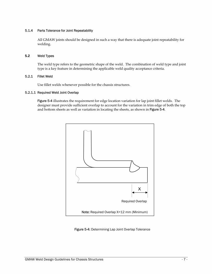
Use fillet welds whenever possible for the chassis structures. 5.2.1.1 Required Weld Joint Overlap
Figure 5-4 illustrates the requirement for edge location variation for lap joint fillet welds. The designer must provide sufficient overlap to account for the variation in trim edge of both the top and bottom sheets as well as variation in locating the sheets, as shown in Figure 5-4.
X
Required Overlap
Note: Required Overlap X=12 mm (Minimum)
Figure 5-4: Determining Lap Joint Overlap Tolerance
GMAW Weld Design Guidelines for Chassis Structures - 7 -
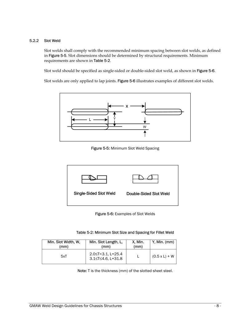
5.2.2 Slot Weld
Slot welds shall comply with the recommended minimum spacing between slot welds, as defined in Figure 5-5. Slot dimensions should be determined by structural requirements. Minimum requirements are shown in Table 5-2.
Slot weld should be specified as single-sided or double-sided slot weld, as shown in Figure 5-6.
Slot welds are only applied to lap joints. Figure 5-6 illustrates examples of different slot welds.
x
Y
W
L
Figure 5-5: Minimum Slot Weld Spacing
Single-Sided Slot Weld Double-Sided Slot WeldSingle-Sided Slot Weld Double-Sided Slot Weld
Figure 5-6: Examples of Slot Welds
Table 5-2: Minimum Slot Size and Spacing for Fillet Weld
Min. Slot Width, W, (mm)
Min. Slot Length, L, (mm)
X, Min. (mm)
Y, Min. (mm)
5xT 2.0≤T<3.1, L=25.4 3.1≤T≤4.6, L=31.8 L (0.5 x L) + W
Note: T is the thickness (mm) of the slotted sheet steel.
GMAW Weld Design Guidelines for Chassis Structures - 8 -

5.2.3 Flare Bevel Groove and Flare V Welds
Applications for the flare welds are tubular structures, brackets and solid round stock.
5.2.3.1 Applicable Joint Types
Flare bevel groove welds may be applied to butt, lap and T-joints where flare V-groove welds are exclusive to butt joints. Figure 5-7 illustrates examples of flare bevel and flare V-groove welds.
Figure 5-7: Examples of Flare V-Groove and Flare Bevel Groove Welds 5.2.3.2 Weld Joint Radius Requirement
Flare bevel groove welds and flare V-groove welds are similar in some respects to fillet welds. However, the flare bevel and flare V-groove welds include a radius surface. This outside surface radius is limited to four times the thickness of the part, as shown in Figure 5-8.
R max
T1
R=4xT1
R max
T1
R=4xT1
Figure 5-8: Weld Joint Radius Limit
GMAW Weld Design Guidelines for Chassis Structures - 9 -
5.3 Weld Size
Please refer to AWS D8.8M: 2007, Section 5.3. 5.4 Weld Quality
Please refer to AWS D8.8M: 2007, Section 5.
5.5 Product Design Considerations 5.5.1 Welding Accessibility
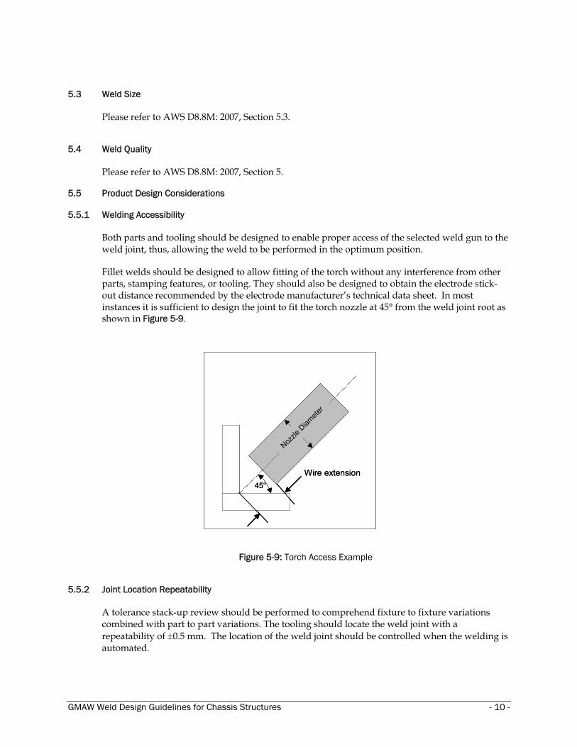
Both parts and tooling should be designed to enable proper access of the selected weld gun to the weld joint, thus, allowing the weld to be performed in the optimum position. Fillet welds should be designed to allow fitting of the torch without any interference from other parts, stamping features, or tooling. They should also be designed to obtain the electrode stick-out distance recommended by the electrode manufacturer’s technical data sheet. In most instances it is sufficient to design the joint to fit the torch nozzle at 45° from the weld joint root as shown in Figure 5-9.
40 m
m
45°Wire extension
Nozzle
Diam
eter
40 m
m
45°Wire extension
Nozzle
Diam
eter
Figure 5-9: Torch Access Example 5.5.2 Joint Location Repeatability
A tolerance stack-up review should be performed to comprehend fixture to fixture variations combined with part to part variations. The tooling should locate the weld joint with a repeatability of ±0.5 mm. The location of the weld joint should be controlled when the welding is automated.
GMAW Weld Design Guidelines for Chassis Structures - 10 -

5.5.3 Weld Design for Reduced Stress Concentration
High stress areas defined by CAE analysis and/or functional testing should be reviewed for weld optimization.
Figure 5-10 illustrates techniques used to reduce the fillet weld stress concentration and to improve weld performance. Good practices include:
• Place weld start/stop away from corners and other high stress areas. • Other examples in stress concentration reductions are shown in Figure 5-10.
a b.
c. d.
Figure 5-10: Reducing Weld Stress Concentrations
GMAW Weld Design Guidelines for Chassis Structures - 11 -

5.5.3.1 Weld Line Design
Abrupt weld line direction change should be avoided whenever possible, as illustrated in Figure 5-11.
Do not start or end welds at corners.
Figure 5-11: Example of Avoiding Abrupt Weld Line Direction Change
5.5.3.2 Location of Weld Overlap
Weld overlap should be placed away from high stress areas, such as corners (as illustrated in Figure 5-10c.), near holes, and other high stress areas resulting from service loading.
5.5.3.3 Location of Tack Weld
Whenever possible tack welds should be placed in low stress areas and kept to a minimum.
5.5.3.4 Minimum Distance between Weld Line and Radius Tangent
Sufficient distance between the weld line and radius tangent (as illustrated in Figure 5-12) is required to make a consistent weld when welding near curved surfaces. This will also reduce the unfavorable effect of additional tensile residual stress in the radius tangent area due from forming of the part. It is recommended that a minimum of 10 mm distance between weld line and radius tangent be maintained (as shown in Figure 5-12).
GMAW Weld Design Guidelines for Chassis Structures - 12 -

X≥10 mm
X: Distance between Weld Line and Radius Tangent
Figure 5-12: Distance between Weld Line and Radius Tangent
5.5.4 Intermittent Welding
Intermittent welds that are properly sequenced can help keep joints closed by reducing the heat input which reduces distortion. Meanwhile, intermittent welds also introduce weld starts and weld stops, both of which are stress risers. Similar to continuous welds, weld start/stops of intermittent welds should be placed away from high stress areas. Intermittent welds are specified by the center-to-center distance (i.e., pitch) and weld length, as shown in Figure 5-13.
Figure 5-13: Intermittent Fillet Weld Spacing
GMAW Weld Design Guidelines for Chassis Structures - 13 -
5.5.5 Slip Plane Configuration
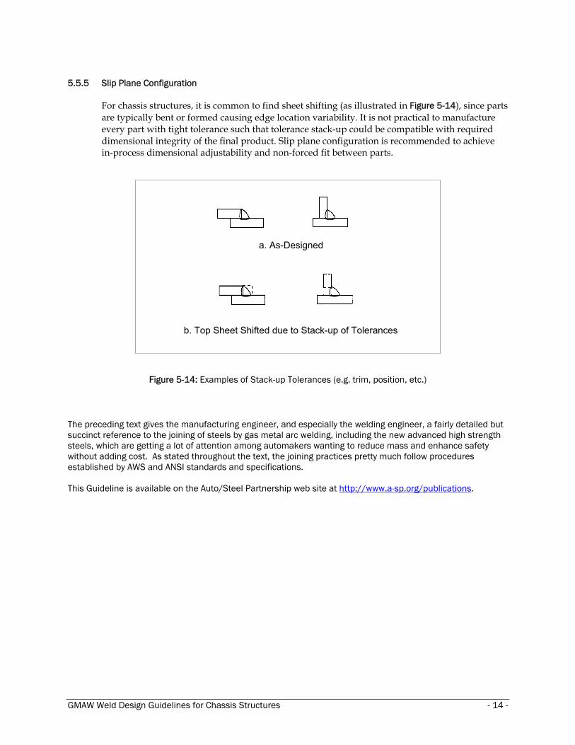
For chassis structures, it is common to find sheet shifting (as illustrated in Figure 5-14), since parts are typically bent or formed causing edge location variability. It is not practical to manufacture every part with tight tolerance such that tolerance stack-up could be compatible with required dimensional integrity of the final product. Slip plane configuration is recommended to achieve in-process dimensional adjustability and non-forced fit between parts.
a. As-Designed
b. Top Sheet Shifted due to Stack-up of Tolerances
Figure 5-14: Examples of Stack-up Tolerances (e.g. trim, position, etc.)
The preceding text gives the manufacturing engineer, and especially the welding engineer, a fairly detailed but succinct reference to the joining of steels by gas metal arc welding, including the new advanced high strength steels, which are getting a lot of attention among automakers wanting to reduce mass and enhance safety without adding cost. As stated throughout the text, the joining practices pretty much follow procedures established by AWS and ANSI standards and specifications. This Guideline is available on the Auto/Steel Partnership web site at http://www.a-sp.org/publications.
GMAW Weld Design Guidelines for Chassis Structures - 14 -


![GMAW chapter22[1]](https://static.fdocuments.in/doc/165x107/577d22881a28ab4e1e97a08e/gmaw-chapter221.jpg)