Glow Worm 30-40-50f boiler instructions
40
Hepworth Heating Ltd., Nottingham Road, Belper, Derbyshire. DE56 1JT General/Sales enquiries: Tel: (01773) 824141 Fax: (01773) 820569 One Contact Local Service Customer Services: Tel: (01773) 828100 Fax: (01773) 828070 221581D.02.00 All replacement parts All labour charges All call-out charges Thank you for installing a new Glow-worm appliance in your home. Glow-worm appliances' are manufactured to the very highest standard so we are pleased to offer our customers' a Comprehensive First Year Guarantee. In the center pages are to be found your Guarantee Registration Card, which we recommend you complete and return as soon as possible. If this card is missing you can obtain a copy or record your registration by telephoning the Heatcall Customer Service number 01773 828100. Our Guarantee gives you peace of mind plus valuable protection against breakdown by covering the cost of: Guarantee Registration Fanned Flue Boilers (S.I.T.) This is a Cat I 2H Appliance BS 6332 BS 5258 Reference in these instructions to British Standards and Statutory Regulations/Requirements apply only to the United Kingdom. For Ireland the rules in force must be used. The instructions consist of three parts, User, Installation and Servicing Instructions, which includes the Guarantee Registration Card. The instructions are an integral part of the appliance and must, to comply with the current issue of the Gas Safety (Installation and Use) Regulations, be handed to the user on completion of the installation. To be left with the user 3558 ❏ ✔ ❏ ✔ ❏ ✔ Instructions for Use Installation and Servicing G.C. No. 41 319 29 G.C. No. 41 319 30 G.C. No. 41 319 31 REGISTER YOUR GLOW-WORM APPLIANCE FOR 1ST YEAR GUARANTEE PROTECTION CALL 0181 380 2555 30F 40F 50F
-
Upload
bandit1958 -
Category
Documents
-
view
4.352 -
download
1
Transcript of Glow Worm 30-40-50f boiler instructions

Hepworth Heating Ltd.,Nottingham Road, Belper, Derbyshire. DE56 1JT
General/Sales enquiries:Tel: (01773) 824141 Fax: (01773) 820569One Contact Local Service
Customer Services:
Tel: (01773) 828100
Fax: (01773) 828070
221581D.02.00
All replacement parts
All labour charges
All call-out charges
Thank you for installing a new Glow-worm appliance in your home.
Glow-worm appliances' are manufactured to the very highest standard so we are pleasedto offer our customers' a Comprehensive First Year Guarantee.
In the center pages are to be found your Guarantee Registration Card, which we recommend you complete andreturn as soon as possible.
If this card is missing you can obtain a copy or record your registration by telephoning the Heatcall CustomerService number 01773 828100.
Our Guarantee gives you peace of mind plus valuable protection against breakdown by covering the cost of:
Guarantee Registration
Fanned Flue Boilers
(S.I.T.)
This is a Cat I2H
Appliance
BS 6332BS 5258
Reference in these instructions to British Standards and StatutoryRegulations/Requirements apply only to the United Kingdom.
For Ireland the rules in force must be used.
The instructions consist of three parts, User, Installation and Servicing Instructions, which includes the Guarantee RegistrationCard. The instructions are an integral part of the appliance and must, to comply with the current issue of the Gas Safety
(Installation and Use) Regulations, be handed to the user on completion of the installation.
To b e l e f t w i t h t h e u s e r
3558
❏✔
❏✔
❏✔
Instructions for UseInstallation and Servicing
G.C. No. 41 319 29 G.C. No. 41 319 30 G.C. No. 41 319 31
REGISTER YOUR GLOW-WORM APPLIANCEFOR 1ST YEAR GUARANTEE PROTECTION
CALL 0181 380 2555
30F 40F 50F

2221581D
Important Information
Introduction 3Lighting the Boiler 4
General Data 1 5Water Systems 2 7Boiler Location 3 10Flue 4 11Preparation 5 13Water Connection 6 18Flue Assembly Installation 7 18Gas Connection 8 20Electrical Connection 9 20Commissioning 10 22Completion 11 25
Servicing 12 26Fault Finding 13 28Replacement Parts 14 33Spare Parts 15 38
CONTENTS DESCRIPTION SECTION PAGE No.
INSTRUCTIONS
FOR USE
INSTALLATION
INSTRUCTIONS
SERVICING
INSTRUCTIONS
Testing and CertificationThis boiler is tested and certificated for safety and performance. It is therefore important that no alteration is made to the boiler, withoutpermission, in writing, from Hepworth Heating Ltd.
Any alteration not approved by Hepworth Heating Ltd., could invalidate the certification, boiler warranty and may also infringe thecurrent issue of the Statutory Requirements, see Section 1.4.
CE MarkThis boiler meets the requirements of Statutory Instrument No. 3083 The boiler (Efficiency) Regulations, and therefore is deemedto meet the requirements of Directive 92/42/EEC on the efficiency requirements for new hot water boilers fired with liquid or gaseousfuels.
Type test for purposes of Regulation 5 certified by: Notified body 0086.
Product/productioncertifiedby: Notified body 0086.
The CE mark on this appliance shows compliance with:
1. Directive 90/396/EEC on the approximation of the laws of the Member States relating to appliances burning gaseous fuels.
2. Directive 73/23/EEC on the harmonization of the Laws of the Member States relating to the electrical equipment designed for use within certain voltage limits.
3. Directive 89/336/EEC on the approximation of the Laws of the Member States relating to electromagnetic compatibility.
INFORMATION FOR THE INSTALLER AND SERVICE ENGINEER.Under Section 6 of The Health and Safety at Work Act 1974, we are required to provide information on substances hazardous tohealth.
CERAMIC FIBRE/INSULATION PADS, GLASS YARN.These can cause irritation to skin, eyes and the respiratory tract. If you have a history of skin complaint you may be susceptible toirritation. High dust levels are usual only if the material is broken. Normal handling should not cause discomfort, but follow normalgood hygiene and wash your hands before eating, drinking or going to the lavatory. If you do suffer irritation of the eyes or severeirritation to the skin seek medical attention.
THERMOSTATSThese contain very small amounts of xylene in the sealed phial and capillary. If broken, under normal circumstances the fluid doesnot cause a problem, but in case of skin contact, wash with cold water. If swallowed drink plenty of water and seek medical attention.
CUT-OFF DEVICESThese contain activated charcoal and a very small amount of chlorodifluormethane in the sealed phial and capillary. If broken, undernormal circumstances the fluid does not cause a problem. If there is irritation to the eyes or skin then seek medical attention.

3 221581D
Instructions for Use
IntroductionPlease read these instructions and follow them carefully for thesafe and economical use of your boiler.
The Economy Plus “F” Range are boilers designed to providecentral heating and indirect domestic hot water from a fullypumped system with a fully indirect cylinder.
Important NoticeThis boiler is for use only on natural gas G20 gas.
Gas Safety (Installation and Use) Regulations.In your interest and that of gas safety it is the Law that ALL gasappliances are installed by a competent person in accordancewith the current issue of the above regulations.
Gas Leak or FaultIf a gas leak or fault exists or is suspected, the BOILER MUSTBE TURNED OFF, including the electrical supply and MUSTNOT BE USED UNTIL THE FAULT HAS BEEN PUT RIGHT.Advice/help should be obtained from your installation/servicingcompany or the local gas undertaking.
Maintenance/ServicingTo ensure the continued efficient and safe operation of theboiler it is recommended that it is checked and serviced asnecessary at regular intervals. The frequency of servicing willdepend upon the particular installation conditions and usage,but in general once a year should be enough.
If this appliance is installed in a rented property there is a dutyof care imposed on the owner of the property by the currentissue of the Gas Safety (Installation and Use) Regulations,Section 35.
It is the Law that any servicing must be carried out by acompetent person.
To obtain service, please call your installer or Heatcall (Glow-worm’s own service organisation) using the telephone numbergiven on the case tray.
Please be advised that the ‘Benchmark’ logbook should becompleted by the installation engineer on completion ofcommissioning and servicing.
All CORGI Registered Installers carry a CORGI ID card, andhave a registration number. Both should be recorded in yourboiler Logbook. You can check your installer is CORGI registeredby calling CORGI direct on :- 01256 372300.
Boiler ClearancesIf fixtures are positioned close to the boiler space must be leftas shown in diagram 3.1. Enough space must also be left infront of the boiler to allow for servicing.
Boilers Installed in a Compartment orCupboardIf the boiler is installed in a cupboard or compartment do notobstruct any ventilation openings.
Do not use the cupboard or compartment for storage.
Regularly make sure that the air vent openings are clear ofobstructions.
CleaningWARNING. This appliance contains metal parts (components)and care should be taken when handling and cleaning, withparticular regard to edges.
Clean the casing occasionally by wiping it over with a dampsoapy cloth or dry polishing duster.
Do not use an abrasive cleaner.
Boiler Electrical SupplyWARNING. The boiler must be earthed.
The boiler must only be connected to a 230V~50Hz supply,protected by a 3A fuse.
All wiring must be in accordance with the current issue ofBS7671.
The colours of three core flexible cable are:
Brown - live, blue - neutral, green and yellow - earth.
As the markings on your plug may not correspond with thesecolours, continue as follows,
The wire coloured blue must be connected to the terminalmarked “N” or “Black”.
The wire coloured brown must be connected to the terminalmarked “L” or “Red”.
The wire coloured green and yellow must be connected to theplug terminal marked “E” or “Green” or the earth symbol " " .
Electrical Supply FailureFailure of the electrical supply will cause the burner to go out.Should this happen, operation of the appliance will normallyresume after the electrical supply is restored.
If the burner does not relight after an electrical supply failure theoverheat device may need resetting, refer to diagram 1, removethe controls tray and press the reset button.
If the cutoff occurs again, turn the appliance off and contact yourinstallation/servicing company.

4221581D
Data/Serial Number LabelThe GC number of the appliance can be found on the Data label,positioned at the top right of the inner cover.
The model name and serial number are located on the controlbox cover, visible when the controls tray is removed.
To Turn the Boiler On
Sealed Water Systems.CAUTION. A sealed water system must be filled and pressurisedby a competent person.
Only light the boiler when you are sure that the system andboiler have been filled and pressurised.
The pressure gauge should show at least 0.7bar, anything lessthan this figure could indicate a leak and you MUST contact yourinstallation/servicing company.
If there is any doubt about the boiler being full of water consultyour installation/servicing company.
All SystemsTurn the electrical supply on to the boiler and check that anyremote controls are set to your requirements (refer tomanufacturer’s instructions for these items).
Remove the controls tray by withdrawing it forwards.
Turn the boiler thermostat knob clockwise to any positionbetween “MIN” and “MAX”, see diagram 1. The maximumsetting is about 82oC (180oF).
The boiler lighting operation is now automatic as follows:
The fan operates, followed by an ignition spark until the pilot islit. When the pilot is alight the ignition switches off and the mainburner lights. The flames can be seen through the viewingwindow.
The main burner will remain alight until switched off by the boilerthermostat or other remote control.
If the boiler thermostat is turned Off, by hand, wait at least 30seconds before turning on again.
When the boiler goes off, both the pilot and main burner go out.
The automatic lighting sequence will operate again when heatis required.
Refit the controls tray.
To Turn the Boiler OffFor short periods, turn thermostat control knob anti-clockwiseuntil “O” is against the setting point. To relight the main burner,turn the thermostat knob clockwise to any setting between ”MIN”and “MAX”.
For longer periods, turn the thermostat control knob anti-clockwise until “O” is against the setting point.
Switch off the electrical supply to the boiler.
To relight follow the sequence given above.
Protection Against FreezingIf the boiler is to be out of use for any long period of time duringsevere weather conditions we recommend that the whole of thesystem, including the boiler, be drained off to avoid the risk offreezing up. Make sure that, if fitted, the immersion heater in thecylinder is switched off.
If you have a sealed water system contact your installation/servicing company as draining, refilling and pressurising mustbe carried out by a competent person.
Diagram 1BOILER CONTROLS
3560VIEWING
WINDOW
CONTROLS TRAY
BOILER THERMOSTAT CONTROL KNOB
OVERHEATCUT-OFFRESETBUTTON
SERIAL No.
SETTINGPOINT
Instructions for Use

5 221581D
1.1 Important NoticeThis boiler is for use only on G20 gas.
The boiler is delivered in one pack.
Wherever possible, all materials, appliances and componentsto be used shall comply with the requirements of applicableBritish Standards.
Where no British Standard exists, materials and equipmentshould be fit for their purpose and of suitable quality andworkmanship.
This boiler must have fully pumped circuits, but is suitable foruse with open vented or sealed water systems.
This boiler is not suitable for outdoor locations.
1.2 Sheet Metal PartsWARNING. When installing or servicing the boiler care shouldbe taken when handling sheet metal parts to avoid any possibilityof personal injury.
1.3 Statutory RequirementsThe installation of the boiler must be carried out by a competentperson in accordance with the relevant requirements of thecurrent issue of:
Manufacturer’s instructions, supplied.
The Gas Safety (Installation and Use) Regulations,The BuildingRegulations, The Building Standards (Scotland) Regulations(applicable in Scotland), local Water Company Bye-laws, TheHealth and Safety at Work Act, The Electricity at WorkRegulations and any applicable local regulations.
102
63
360
600
45
86
60
42
300
WATER CONNECTIONS FLUETERMINALDETAILGAS CONNECTIONS
122
*
55
from boiler top.58mm from inner case top.*
122
108
BOILERCL
6472
Diagram 1.1
LIFTING
WEIGHT
Rc 1/2 (1/2 in. BSPT)GASCONNECTION
WATERCONNECTION
22mm copper,flow at right, return at left
45W, internal fuse F1A.ELECTRICITYRATING
WATERCONTENT
TOTAL
WEIGHT
230V~50Hz Fused 3A
DATA LABEL On the inner case front
TABLE 1. ECONOMY PLUS DATA
ELECTRICITYSUPPLY
30F/40F/50F
21.7Kg(47.8lb)
27.6Kg(60.8lb)
0.6litre(1.0pt)
MODELS
GENERALARRANGEMENT
260
36
Detailed recommendations are contained in the current issue ofthe following British Standards and Codes of Practice, BS4814,BS5440 Part 1 and 2, BS5449, BS5546, BS6700, BS6798,BS6891, BS7074 Part 1 and 2, BS7478, BS7593, BS7671.
Manufacturer’s notes must not be taken as overriding statutoryobligations.
1 General
350

6221581D
1.4 B.S.I. CertificationThe boiler is certificated to the current issue of BS6332 Part 1,invoking the current issue of BS5258 Part 1 for performanceand safety. It is, therefore, important that no alteration is madeto the boiler, without permission, in writing, from HepworthHeating Ltd.
Any alteration that is not approved by Hepworth Heating Ltd.,could invalidate the B.S.I. Certification of the boiler, the warrantyand could also infringe the current issue of the StatutoryRequirements.
1.5 General DataThe data label is positioned on the inner case visible when thefront panel is removed.
The serial number plate is positioned on the control box cover,visible when the controls tray is removed.
The General Arrangement diagram 1.1 and all other dimensionsare given in millimetres.
General Data refer Table 1
The Seasonal Efficiency Domestic Boilers UK (SEDBUK) is
(30F) 75.6%
(40F) 77.0%.
(50F) 76.3%.
The value is used in the UK Government’s Standard AssessmentProcedure (SAP) for energy rating of dwellings. The test datafrom which it has been calculated have been certified by B.S.I.
1.6 Range RatingThe boiler is range rated and is factory set to maximum, it maybe adjusted to suit individual system requirements, refer to DataTable 2.
1.7 Gas SupplyThe gas installation must be in accordance with the currentissue of BS6891.
The supply from the governed meter must be of adequate sizeto provide a steady inlet working pressure of 20mbar (8in wg) atthe boiler.
On completion, test the gas installation for soundness using thepressure drop method and suitable leak detection fluid, purgein accordance with the above standard.
1.8. Electrical SupplyWARNING. This boiler must be earthed.
All system components shall be of the approved type and wiringshall comply with and be connected in accordance with therequirements of the current issue of BS7671 and any applicablelocal regulations.
Connection of the boiler and system controls to the mainssupply must be through a common isolator and must be fused3A maximum. This method of connection should be, preferably,by a fused double pole isolating switch, provided it has aminimum contact separation of 3mm on both poles. This shouldbe readily accessible and preferably adjacent to the appliance.It should supply the appliance only and be easily identifiable asso doing.
Alternatively an unswitched shuttered socket outlet and 3Afused 3 pin plug both to the current issue of BS1363 may beused provided that they are not used in a room containing a bathor shower.
Wiring to the boiler must be PVC insulated type to the currentissue of BS6500 Table 16, not less than 0.75mm2(24/0.20mm).
RANGE RATINGNOMINAL Btu/hHEATINPUT(GROSS) kW
NOMINAL Btu/hHEATOUTPUT kW
BURNER m barSETTINGPRESSURE in.w.g
APPROX m3hGASRATE ft3h
TABLE 2. MODEL 50F
50,600 56,250 61,730
14.83 16.49 18.09
1.4 1.6 1.7
50 56 61
min medium max
40,000 45,000 50,000
11.72 13.19 14.65
10.4 13.0 15.4
4.2 5.2 6.2
RANGE RATING
NOMINAL Btu/hHEATINPUT(GROSS) kW
NOMINAL Btu/hHEATOUTPUT kW
BURNER m barSETTINGPRESSURE in.w.g
APPROX m3hGASRATE ft3h
min medium max
1.1 1.2 1.4
37.9 43.7 49.3
30,000 35,000 40,000
8.79 10.26 11.72
37,970 43,750 49,380
11.13 12.82 14.47
TABLE 2. MODEL 40F
8.5 11.4 14.3
3.4 4.6 5.7
RANGE RATINGNOMINAL Btu/hHEATINPUT(GROSS) kW
NOMINAL Btu/hHEATOUTPUT kW
BURNER m barSETTINGPRESSURE in.w.g
APPROX m3hGASRATE ft3h
min medium max
0.7 0.9 1.0
25.3 31.2 37.0
20,000 25,000 30,000
5.86 7.33 8.79
25,310 31,250 37,040
7.42 9.16 10.85
TABLE 2. MODEL 30F
5.9 9.6 13.3
2.3 3.9 5.3
1.9 Heating System ControlsThe heating system should have installed: a programmer androom thermostat controlling the boiler.
Thermostatic radiator valves may be installed in addition to theroom thermostat.
Note: For further information, see The Building Regulations1991 - Conservation of fuel and power, 1995 edition - AppendixG, table 4b.
1.10 Anti-theft KitsAnti-theft kits are available for these appliances, contactHepworth Heating Ltd. for further information.
1 General
7 221581D
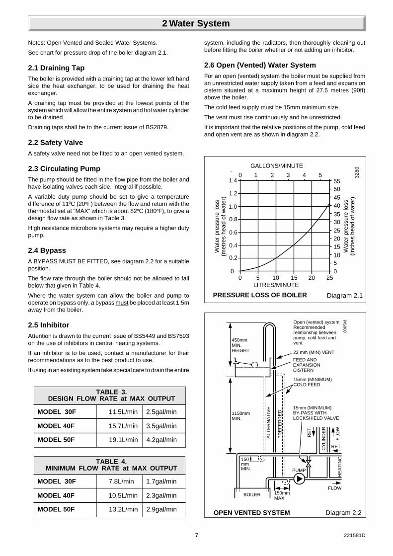
Notes: Open Vented and Sealed Water Systems.
See chart for pressure drop of the boiler diagram 2.1.
2.1 Draining TapThe boiler is provided with a draining tap at the lower left handside the heat exchanger, to be used for draining the heatexchanger.
A draining tap must be provided at the lowest points of thesystem which will allow the entire system and hot water cylinderto be drained.
Draining taps shall be to the current issue of BS2879.
2.2 Safety ValveA safety valve need not be fitted to an open vented system.
2.3 Circulating PumpThe pump should be fitted in the flow pipe from the boiler andhave isolating valves each side, integral if possible.
A variable duty pump should be set to give a temperaturedifference of 110C (20oF) between the flow and return with thethermostat set at “MAX” which is about 82oC (180oF), to give adesign flow rate as shown in Table 3.
High resistance microbore systems may require a higher dutypump.
2.4 BypassA BYPASS MUST BE FITTED, see diagram 2.2 for a suitableposition.
The flow rate through the boiler should not be allowed to fallbelow that given in Table 4.
Where the water system can allow the boiler and pump tooperate on bypass only, a bypass must be placed at least 1.5maway from the boiler.
2.5 InhibitorAttention is drawn to the current issue of BS5449 and BS7593on the use of inhibitors in central heating systems.
If an inhibitor is to be used, contact a manufacturer for theirrecommendations as to the best product to use.
If using in an existing system take special care to drain the entire
2 Water System
0
25201510
00 5 10 15 20 25
LITRES/MINUTE
Wat
er p
ress
ure
loss
(met
res
head
of w
ater
)
Wat
er p
ress
ure
loss
(inch
es h
ead
of w
ater
)
5
30
0 1 2 3 4 5
GALLONS/MINUTE
35
4540
5055
3280
0.2
0.4
0.6
0.8
1.0
1.2
1.4
MODEL 50F 13.2L/min 2.9gal/min
TABLE 3.DESIGN FLOW RATE at MAX OUTPUT
MODEL 30F 11.5L/min 2.5gal/min
MODEL 40F 15.7L/min 3.5gal/min
MODEL 50F 19.1L/min 4.2gal/min
TABLE 4.MINIMUM FLOW RATE at MAX OUTPUT
MODEL 30F 7.8L/min 1.7gal/min
MODEL 40F 10.5L/min 2.3gal/min
Diagram 2.1PRESSURE LOSS OF BOILER
Diagram 2.2OPEN VENTED SYSTEM
Open (vented) system.Recommendedrelationship betweenpump, cold feed andvent.
22 mm (MIN) VENT
FEED ANDEXPANSIONCISTERN
15mm (MINIMUM)COLD FEED
15mm (MINIMUM)BY-PASS WITHLOCKSHIELD VALVE
450mmMIN.HEIGHT
1150mmMIN.
150mmMIN.
BOILER
PUMP
150mmMAX
FLOW
RET.
ALT
ER
NA
TIV
E
PR
EF
ER
RE
D
RE
T.
CY
LIN
DE
R
FLO
WH
EA
TIN
G00
05M
system, including the radiators, then thoroughly cleaning outbefore fitting the boiler whether or not adding an inhibitor.
2.6 Open (Vented) Water SystemFor an open (vented) system the boiler must be supplied froman unrestricted water supply taken from a feed and expansioncistern situated at a maximum height of 27.5 metres (90ft)above the boiler.
The cold feed supply must be 15mm minimum size.
The vent must rise continuously and be unrestricted.
It is important that the relative positions of the pump, cold feedand open vent are as shown in diagram 2.2.

8221581D
2.7 Domestic Hot Water CylinderThe hot water cylinder must be of the double feed fully indirecttype. Not the single feed self priming type.
2.8 Sealed Water SystemsThe installation must comply with the appropriate requirementsof the current issue of BS5449, BS6759, BS6798, BS4814 andBS7074 Part 1 and 2.
See diagram 2.3 for a suggested layout.
2.9 Safety ValveA safety valve must be fitted to a sealed water system.
It shall be preset, nonadjustable with a lift pressure of 3bar,incorporating seating of a resilient material, a test device and aconnection for drain.
The drain from the safety valve must be routed clear of anyelectrical fittings and positioned so that any discharge can beseen.
Diagram 2.3SEALED WATER SYSTEM DIAGRAMMATIC LAYOUT
3 LITRES (0.66 gals)MAKE-UP BOTTLE(if required)
NON-RETURNVALVE
AUTOAIRVENT
FLOW
DRAINCOCK
BOILER
SAFETYVALVE
(Make-upalternatives) EXPANSION
VESSEL
PRESSUREGAUGE
CIRCULATINGPUMP
FILLING POINT
AIRRELEASEPOINT
HE
AT
ING
CIR
CU
IT
15mm (min)BY-PASS WITHLOCKSHIELD VALVE
RETURN
5812
2 Water System
2.10 Expansion VesselA diaphragm type expansion vessel, conforming to the currentissue of BS4814 (see also BS7074 Part 1 and 2) must beconnected at a point close to the inlet side of the circulatingpump, see the diagrammatic layout, diagram 2.3, unless laiddown differently by the manufacturer.
The expansion vessel volume depends on the total watersystem volume and the initial system design pressure. For anysystem an accurate calculation of vessel size is given in thecurrent issue of BS7074 Part 1.
Example: For an initial system design pressure of 0.7bar, theminimum total vessel volume required is 0.063xTotal Systemvolume.
Note: A higher initial design pressure requires a larger volumeexpansion vessel.
Guidance on vessel sizing is also given in the current issue ofBS5449 and BS7074 Part 1.
The charge pressure must not be less than the static head of thesystem, that is, the height of the highest point of the systemabove the expansion vessel.
The water content of the boiler is given in the Data Table 1.

9 221581D
METHOD 1
SUPPLY STOPVALVESUPPLY
PIPE
HOSEUNIONS
SERVICINGVALVE
TEMPORARYHOSE
HEATINGSYSTEM
COMBINEDCHECK VALVEAND VACUUMBREAKER
0051M
Diagram 2.4
METHOD 3 Cistern filling method
METHOD 2 Mains topping up method
METHOD 1 Mains topping up method
FILLING A SEALED SYSTEM
METHOD 2 HEATINGSYSTEMTEMPORARY
HOSE
HOSEUNIONS
SERVICINGVALVE
SUPPLYPIPE
SUPPLY STOPVALVE
DOUBLE CHECKVALVE ASSEMBLY
HEATINGSYSTEMSERVICING
VALVE
SUPPLYSTOP VALVE
SUPPLYPIPE
HOSEUNIONS DOUBLE CHECK
VALVE ASSEMBLY
OVERFLOWCISTERN
PRESSUREREDUCINGVALVE
2 Water System
2.11 Pressure GaugeA pressure gauge with a set pointer and covering at least 0 to4 bar (0 to 60lb in2) shall be fitted permanently to the system ina position where it can be seen when filling the system.
2.12 Domestic Hot Water CylinderSINGLE FEED INDIRECT CYLINDERS ARE NOT SUITABLE.
The hot water cylinder must be of the indirect coil type. It mustbe suitable for working at a gauge pressure of 0.35 bar abovethe safety valve setting.
2.13 Water MakeupProvision should be made for replacing water loss from thesystem using a make up bottle or filling loop mounted in aposition higher than the top point of the system, connectedthrough a non-return valve to the return side of either theheating circuit or the hot water cylinder.
Alternatively, provision for make up can be made by using afilling loop.
2.14 Filling a Sealed Water SystemProvision for filling the system at low level must be made. Threemethods are shown in diagram 2.4. There must be no permanentconnection to the mains water supply, even through a non-return valve.

10221581D
Diagram 3.1CLEARANCES
C
D D
EE
APERMANENTSURFACE
B
MINIMUM CLEARANCESABCDE
50078
*105
**
To a permanent surface
SIDE FLUE - 220mm
REAR FLUE - 120mm
WHERE EXTERNAL ACCESS TOTHE FLUE IS NOT PRACTICAL THENCLEARANCE OPPOSITE THE EXITMUST BE ADEQUATE TO PERMITINSTALLATION OF THE FLUE ASSEMBLY
0073
M
TABLE 5. COMPARTMENT AIR VENTS
VENTILATIONREQUIREMENTS
cm2 in2 cm2 in2
VENTILATIONFROMROOMOR SPACE
MODEL
HIGH LEVEL LOW LEVEL
VENT AREA VENT AREA
30F
40F
50F
30F
40F
50F
- - - -
131 20 131 20
163 25 163 25
- - - -
66 10 66 10
82 12.5 82 12.5
VENTILATIONFROMOUTSIDE
3.1 Boiler LocationThe boiler may be installed in any room although particularattention is drawn to the requirements of the current issue ofBS7671 with respect to the installation of a boiler in a roomcontaining a bath or shower. Any electrical switch or boilercontrol using mains electricity should be so situated that itcannot be touched by a person using the bath or shower.The electrical provisions of the Building Standards (Scotland)are applicable to such installations in Scotland.
The boiler must be mounted on a flat wall which is sufficientlyrobust to take its total weight, see Data Table 1.
3.2 Boiler ClearancesThe boiler must be positioned so that at least the minimumoperational and servicing spaces are as shown in diagram 3.1.
Additional clearance may be required around the boiler forinstallation purposes, dependant upon site conditions.
3.3 Timber Frame BuildingsIf the boiler is to be installed in a timber frame building it shouldbe fitted in accordance with the Institute of Gas Engineersdocument IGE/UP/7/1998. If in doubt seek advice from the localgas undertaking or Hepworth Heating Ltd.
3.4 Room VentilationThe boiler is room sealed, so when installed in a room or spacea permanent air vent is not required.
3.5 Cupboard or Compartment Ventilation30F only : Does not require cupboard or compartment ventilation.
40F, 50F : Where the boiler is fitted in a cupboard orcompartment, permanent high and low level ventilation must beprovided. The ventilation areas required are given in Table 5.
Where the installation of the boiler will be in an unusual location,special procedures are necessary, refer to the current issue ofBS6798 for guidance.
Make sure that the cupboard or compartment air vents arepositioned to be clear of obstructions at all times.
A compartment used to enclose the boiler must be designedand constructed specifically for this purpose.
An existing cupboard or compartment modified for the purposemay be used. Refer to the current issue of BS6798 for guidance.
The doorway opening should be of sufficient size to allow foreasy removal of the boiler.
3 Boiler Location

11 221581D
A
A
FG E
A
G
G
G
B,C B,C
F FK
K
K
C
G
L L
UNDER CAR PORT etc.
H,I
JD
FK
4.1 FlueThe flue must be installed in accordance with the current issueof BS5440 Part 1.
The air and flue duct connect to the top of the boiler using anelbow which can be positioned to the sides or rear.
The standard flue is able to provide the duct lengths rangesshown in diagram 4.2 rear flue and 4.3 side flue.
If a longer flue duct is required, do not extend the ductings. Along flue system and terminal can be supplied. This is able toprovide the duct length range as shown in diagram 4.2 for a rearflue, diagram 4.3 for a side flue.
4.2 Terminal PositionThe minimum acceptable spacings from the terminal toobstructions and ventilation openings are as shown in diagram4.1.
The boiler must be installed so that the terminal is exposed tothe external air.
It is important that the position of the terminal allows the freepassage of air across it at all times.
Car ports or similar extensions of a roof only, or a roof and onewall require special consideration with respect to any openings,doors, vents or windows under the roof. Care is required toprotect the roof if it is made of plastic sheeting.
If the car port comprises of a roof and two or more walls, seekadvice from the local gas company before installing the boiler.
Where the terminal is fitted within 600mm (24in) below plasticguttering an aluminium shield 1500mm (5ft) long should befitted to the underside and immediately beneath the guttering oreaves.
Where the terminal is fitted within 450mm (18in) below eaves orpainted guttering an aluminium shield 750mm (2ft6in) longshould be fitted to the underside and immediately beneath theguttering or eaves.
4 Flue
MINUMUM SITING DIMENSIONS FORFANNED FLUE TERMINALSPOSITION
MINIMUMSPACING
A DIRECTLY BELOW AN OPENABLE mmWINDOW, AIR VENT, OR ANY OTHERVENTILATION OPENING 300
B BELOW GUTTER, DRAIN/SOIL PIPE 75C BELOW EAVES 200D BELOW A BALCONY OR CAR PORT 200E FROM VERTICAL DRAIN PIPES AND
SOIL PIPES 75F FROM INTERNAL OR EXTERNAL 300
CORNERSG ABOVE ADJECENT GROUND OR
BALCONY LEVEL 300H FROM A SURFACE FACING THE
TERMINAL 600I FACING TERMINALS 1200J FROM OPENING (DOOR/WINDOW) IN
CAR PORT INTO DWELLING 1200K VERTICAL FROM A TERMINAL 1500L HORIZONTALLY FROM A TERMINAL 300
Diagram 4.1
0161
M
2861

12221581D
4.3 Terminal GuardA terminal guard is required if persons could come into contactwith the terminal or the terminal could be subject to damage.
If a terminal guard is required, it must be positioned to providea minimum of 50mm clearance from any part of the terminal andbe central over the terminal, see diagram 4.1.
A suitable terminal guard can be obtained from:
Tower Flue Components Ltd., Morley Road, Tonbridge, Kent.
TN9 1RA
their reference K3.
4.4 Flue Collar Kit / Wall Liner KitA flue collar kit, part No. 443286 (with instructions) is available.
This can be used to cover the flue, as shown in diagram 4.4.
Please note, the use of this collar will mean that the flue lengthswill need to be altered, full instructions are given in the kit.
If required, an optional Wall Liner Kit, part No.900862, isavailable, complete with fixing instructions.
6891
Side Flue LengthsRear Flue Lengths
Diagram 4.3AFLUE COLLAR KIT
3774
1m FLUE PACK 75 mm to 961 mm
2m FLUE PACK 75 mm to 1961mm
3m FLUE PACK 75 mm to 2941mm
STD FLUE PACK 75 mm to 469 mm
Diagram 4.2REAR FLUE
1m FLUE PACK 260 mm to 1080 mm
2m FLUE PACK 260 mm to 2080 mm
3m FLUE PACK 260 mm to 3060 mm
STD FLUE PACK 260 mm to 585 mm
SIDE FLUE Diagram 4.3
S
R
4 Flue

13 221581D
5.1 UnpackingOpen the carton, check the items supplied against the list on thecarton flap diagram 5.1.
5.2 Flue PreparationAll flue assemblies are designed for internal installation (optionalwall liner is required), given that there is sufficient clearancesopposite to the flue for the installation of the flue.
If there is insufficient clearance the flue can be installed fromoutside.
For a wall thickness up to 300mm, provided that there issufficient space and the optional wall liner kit is used the flue canbe fully installed from the inside.
For a wall thickness of over 300mm the external flue hole willneed to be made good from the outside. This applies also if youuse the flue kit without the optional kit, irrespective of wallthickness.
FITTINGS PACK
INSTALLATIONLITERATURE
USERLITERATURE
BOILER
CARTON
Diagram 5.1BOILER PACK CONTENTS
4796
TEMPLATE
Diagram 5.3WALL TEMPLATE(Side and Rear)
3286
REAR FLUE
115mmMINIMUMHOLE
122mm
5.3 Rear and Side Flue ApplicationSelect the boiler location and flue application, with due regardto the terminal position:
Take the template from the boiler pack and temporarily positionit on the wall, making sure that the minimum clearances aremaintained, see diagram 3.1.
Note: The template has “Fixture’s” alignment marks for ease ofinstallation.
For rear flue, mark the position of the flue as diagram 5.3.
For side flue, extend the centre line horizontally left or right to thecorner of the adjacent surface where the flue is required to exitto outside. Mark the position of the centre of the flue, as diagram5.3
5.4 Flue Hole CuttingHaving marked out the flue centre cut a hole for the flue using,preferably, a 115mm minimum core drill.
5 Preparation

14221581D
5.5 Wall Mounting BracketReposition the template, ensuring dimensional alignment withthe flue hole.
Mark the boiler securing screws and mounting plate position,see diagram 5.4.
Drill holes and plug, to suit No.10x50 woodscrews, fit the screwsallowing sufficient clearance to accept the keyhole fixing brackets.
Secure the boiler mounting plate to the wall with No.10x50woodscrews and plugs, see diagram 5.4.
SECURINGSCREW (2)
MOUNTINGPLATE
5mm
TEMPLATE
TOP BOILERMOUNTING
HOLES
MOUNTING PLATEFIXING POINT
5.5ø
3/16 ø PLUG
No. 10x1/2 in.
5.5ø
3/16 ø PLUG00
64M
Diagram 5.4BOILER MOUNTING andPLATE FIXING POINTS
5 Preparation
5.6 Flue Duct (Standard or Long)Mark the duct to the length required (this length allows forexpansion), see diagram 5.5 for Rear flue and diagram 5.6 forSide flue, then cut square and remove any burrs.

15 221581D
5.7 Air Duct/Terminal (Standard or Long)Mark the duct length, see diagram 5.7 for Rear flue and diagram5.8 for Side flue, then cut square and remove any burrs.
5.8 Air Duct/Terminal and Flue Duct AssemblyLocate the flue duct into the air duct/terminal, see diagram 5.9.
Fully locate the flue elbow into the air/terminal and flue ductassembly as shown, ensuring correct alignment of the “Top”,see diagram 5.10.
Mark the position of securing holes through the flue elbowoutlet, see diagram 5.10.
Drill two 3mm diameter holes, see diagram 5.10.
5.9 External Flue InstallationRemove the flue elbow from the air duct/terminal and flue ductassembly.
Note: Do not insert the flue assembly but place on one side untilrequired.
Continue at “Boiler Preparation”
5.10 Internal Flue InstallationIf access to the outside wall is not practical, the flue system canbe installed from inside. Use of the optional wall liner kit isrequired.
Secure the flue elbow to the air duct/terminal with the two selftapping screws supplied in the fittings pack, see diagram 5.10.
Diagram 5.6FLUE DUCT (SIDE FLUE)
* S minus 37mm(If flue collar is to be fitted overall
dimension increased by 15mm)
* S Minus 52mm
BOILERCENTRELINE
s
Diagram 5.7REAR FLUEAIR DUCT / TERMINAL
*Increase dimension by 15mm if the“Optional Flue Collar” is to be fitted.
LONG FLUETERMINAL
STANDARD FLUETERMINAL
* Q plus 60mm
Q
Diagram 5.5FLUE DUCT (REAR FLUE)
*Increase dimension by 15mm if the“Optional Flue Collar” is to be fitted.
FLUE DUCT
* Q plus 70mm
Q
6893
Standard flue terminal illustrated
6894
5 Preparation

16221581D
Diagram 5.9AIR DUCT /TERMINAL ASSEMBLY
FLUEDUCT
AIR DUCT / TERMINALASSEMBLY
Diagram 5.8
* S minus 47mm(If flue collar is to be fitted overall
dimension increased by 15mm)
SIDE FLUEAIR DUCT / TERMINAL
LONG FLUETERMINAL
STANDARDFLUETERMINAL
* S plus 60mm
BOILERCENTRELINE
s
6895
Diagram 5.10FLUE ELBOW ASSEMBLY
3mm
DRILL SIZE
SEAL WITHTAPE SUPPLIED
AIR DUCT/TERMINAL &FLUE DUCT ASSEMBLY
FLUE ELBOWASSEMBLY
REAR FLUESECURING POINTS
SIDE FLUESECURING POINTS
LHD/RHD
LHDRHD
FLUE ELBOW ASSEMBLY
3293
3294
Place the sealing tape from the fittings pack around the flueelbow as diagram 5.10.
Place the flue assembly to one side until required.
Continue at “Boiler Preparation”.
5.11 Wall LinerIf a wall liner is used, fit self adhesive seal as follows:
For wall thicknesses up to 300mm fit the self adhesive seal tothe air duct, see diagram 5.11, make sure the joint is on top.
For wall thicknesses over 300mm see diagram 5.12..
When installed the seal will be within the wall.
5.12 Boiler PreparationRemove the controls tray and outer case and place on one sideuntil required, see diagram 5.13.
Discard packing piece from between front cover and inner case.
Note: If convenient, a connection can be made to the gasservice at this time.
Lift the boiler into position above the boiler mounting plate,lowering the boiler into position at the same time locating thekey hole slots of the boiler on to the securing screws, whenlocated secure the screws, see diagram 5.14.
5 Preparation

17 221581D
5 Preparation
Diagram 5.11FOAM SEAL(Wall Thickness up to 300mm)
*Increase dimension by 15mm if the“Optional Flue Collar” is to be fitted.
* 10mm
FOAM SEAL
Q
Diagram 5.12
FOAM SEAL(Wall Thickness over 300mm)
Q minus 25mm
Q
FOAM SEAL
6896
6897
CONTROLTRAY
CASE REMOVAL Diagram 5.13
BOILER MOUNTING
KEYHOLE SLOTMOUNTING BRACKET
FRONT COVER
4810
Diagram 5.14
MOUNTINGPLATE
3550WITH WALL LINER KIT ONLY
WITH WALL LINER KIT ONLY

18221581D
Make the water connection to the heating system, see diagram6.1.
The boiler has compression connections, with nuts and olivessupplied loose in the fittings pack, to accept 22mm outsidediameter copper tubing to BS2871.
The right hand connection is the flow from the boiler.
6 Water Connection
Diagram 6.1WATER CONNECTION
COPPERTUBING
RETURN FLOW
3551
7 Flue Assembly Installation
7.1 Flue Assembly - PreparationRemove the inner case by releasing the securing screws, placeon one side until required, see diagram 7.1.
Remove the violet (or blue) and red electrical connections fromthe fan see diagram 7.2.
Break the air pressure switch tube(s) connection(s), see diagram7.2.
Slacken but do not remove the flue hood securing angle wingnuts, see diagram 7.2.
Remove the fan and mounting plate assembly by removing thetwo securing screws, see diagram 7.2.
7.2 External Flue InstallationOffer the air duct/terminal flue duct assembly into and throughthe hole and wall.
Secure the flue elbow to the air duct/terminal with the two selftapping screws supplied in the fittings pack, into the holespreviously drilled.
Place the sealing tape from the fittings pack around the flueelbow as diagram 5.11.
Continue at “Flue/Boiler connection.
7.3 Internal Flue InstallationPush the flue assembly into and through the wall, see diagram7.3. Diagram 7.1INNER CASE
DATA LABEL
PILOTVIEWINGWINDOWSERIAL
NO PLATE
SECURINGSCREW (4)
INNERCASE
7888
UNION NUT
OLIVE
WATERCONNECTION

19 221581D
Diagram 7.2FLUE PREPARATION
FAN ELECTRICALCONNECTIONS
CLEAR
SECURINGSCREW (4)
FAN / MOUNTINGPLATE ASSY.SECURINGSCREW (2)
COMBUSTIONCHAMBERFRONT PANEL
3303
7 Flue Assembly Installation
6932
RESTRICTOR
INTERNAL FLUE ASSEMBLY 40F
GASKET
Diagram 7.3
7.4 Flue/Boiler ConnectionSecure the flue elbow restrictor (not fitted 50F) and gasket to theboiler with the three screws and washers previously removed,see diagram 7.4.
Replace the fan and mounting plate assembly ensuringengagement of the fan into the flue elbow and the fan retainingbracket, see diagram 7.5 and secure with the two screwspreviously removed.
Connect air pressure switch tubes, electrical connections.
Make good around the flue and flue terminal and fit terminalguard.
Diagram 7.3
6933
Diagram 7.4FLUE ASSEMBLY /BOILER CONNECTION
WASHER (3) SECURINGSCREW (3) 35
54
Diagram 7.5FLUE ELBOW SPIGOT
3344
GASKET
RESTRICTOR
INTERNAL FLUE ASSEMBLY 30F
RED
AIR PRESSURESWITCH TUBES
FLUE HOODWING NUTS
FLUE ELBOWSPIGOT
FAN RETAININGBRACKET

20221581D
8 Gas Connection.Make the gas connection, see diagram 8.1.
Diagram 9.1CABLE RETAINING CLIPS
SELF ADHESIVEBACKED CABLECLIPS
3555
Diagram 8.1
8 Gas Connection
9 Electrical Connection
9.1 Electrical ConnectionWARNING. This boiler must be earthed.
Take the two plastic cable retaining clips, from the loose itemspack, peel off the backing paper and position them as shown indiagram 9.1.
GAS SERVICECOCK
COVERSCREW
MAIN BURNERPRESSURETEST POINT
NOTE: Do not adjust anyother setting screws
7378
GASPRESSUREADJUSTMENTSCREWMULTIFUNCTIONAL
CONTROL

21 221581D
Remove the control box by supporting it and removing the fixingscrew, lower slightly and pull forwards to disengage, supportthe box on the lip bracket at the front, see diagram 9.2.
Take care not to damage any internal wiring and capillaries.
Using heat resistant (85oC) PVC insulated cable of at least0.75mm2(24/0.2mm to the current issue of BS6500 Table 16,and of a suitable length, thread the cable through the cableclamp secure into the plastic clips and connect to the appropriateterminals, see diagram 9.3 and 13.5.
Standard colours are, brown - live (L), blue - neutral (N) andGreen/Yellow - earth (E) .
The mains cable outer insulation must not be cut back externalto the cable clamp, see diagram 9.3.
When making connections, make sure that the earth conductoris made of greater length than the current carrying conductors,so that if the cable is strained the earth conductor would be thelast to become disconnected.
It is essential that the polarity is correct.
9.2 Pump ConnectionThe pump must be connected directly to the control box, asshown in diagram 9.3 and 13.5 threading the cable through thecable clamp in the side of the control box.
9.3 External ControlsRemove the red link between 9 and SL in the control box whenusing any external controls.
Always make sure that all cables are secured and clear of hotsurfaces.
9.4 Testing - ElectricalChecks to ensure electrical safety should be carried out by acompetent person.
After installation of the system, preliminary electrical systemchecks as below should be carried out.
1. Test insulation resistance to earth of mains cables.
2. Test the earth continuity and short circuit of all cables.
3. Test the polarity of the mains.
9 Electrical Connection
Diagram 9.3CONTROL BOX TERMINAL
3310
Remove red ink between 9 & SL When fittinga time control etc (if no switch is fitted, linkwill make the circulation pump run constantly)
PUMPCABLE
CABLECLAMPS
MAINSCABLE
Diagram 9.2
SECURINGSCREWS (2)
5739
LIP BRACKET

22221581D
10.1 PreliminariesThe system must be thoroughly flushed out with cold waterwithout the pump in position.
Refit the pump and fill the system, making sure that all the air isproperly vented from the system and pump.
10.2 Sealed SystemsFlush the whole system with cold water without the pump inposition. Refit the pump and fill until the pressure gaugeregisters 2.7 bar (40lbf/in2). Clear any air locks and check forleakage.
Check the operation of the safety valve preferably by allowingthe water pressure to rise until the valve lifts. This should bewithin +/- 0.3 bar (+/- 4.3lbf/in2), of the preset pressure. Wherethis is not possible a manual check should be carried out.
Release the cold water to initial design pressure.
10.3 Initial Lighting, Testing and AdjustmentIdentify the controls by reference to diagram 10.1.
Check that the main electrical supply to the boiler is switched offand that the boiler thermostat is turned to “O”, see diagram 10.1.
Turn on the main gas supply at the gas service cock.
Test the pilot supply tube and its connections for gas soundnessas follows:
Remove the combustion chamber front panel securing screws,see diagram 10.2.
Switch on the electrical supply to the boiler and heating system.Make sure that any remote controls are calling for heat.
WARNING: The gas valve, fan and control box operate onmains voltage, terminals will become “Live”.
Turn the boiler thermostat knob fully clockwise and the fan willoperate. Sparks will be generated and the pilot burner will light.
To complete this test it is necessary to operate the boiler withoutits inner case, BUT UNDER ALL OTHER CIRCUMSTANCESthe inner case must be correctly fitted and sealed.
Test for gas soundness around the pilot connections usingsuitable leak detection fluid.
At this time check that the flame lengths are as shown indiagram 10.3.
10 Commissioning
Diagram 10.3
Diagram 10.2COMBUSTION CHAMBER
FLAME LENGTHAND SPARK GAP
FLUE HOODWING NUTS
COMBUSTIONCHAMBERFRONT PANEL
SECURINGSCREW (4)
SPARK GAP3 to 4.5
3312
3345
12 to 14 FLAME LENGTH
BOILER CONTROLS Diagram 10.1
Note:control box shown inservice position.
SETTINGPOINT
3311
OVERHEATRESETBUTTON
THERMOSTATCONTROL KNOB
INDICATORSLOT
4085

23 221581D
The pilot gas rate is preset and must not be adjusted. The stepadjustment screw must not be touched.
Turn the thermostat knob to "O" and isolate the boiler from theelectrical supply.
Refit the combustion chamber front panel, secure the fluehoodsecuring angle wing nuts and inner case with the screwspreviously removed.
For reference stick the self adhesive arrow indicator, from thefittings pack, to the data badge against the rating the boiler isgoing to be set to.
Loosen the main burner pressure test point screw and fit asuitable pressure gauge, see diagram 10.4.
WARNING: The gas valve, fan and control box operate onMAINS voltage, terminals will become “Live”.
Note: The neon indicator lights on the control board (PCB) arean aid to fault finding.
Make sure that any remote controls are calling for heat.
Switch on the electrical supply to the boiler and heating system.
Turn the boiler thermostat knob fully clockwise to the maximumsetting.
The lighting sequence is automatic, as follows:
The fan operates
The spark ignition operates
The pilot solenoid opens
The pilot burner lights
The ignition spark stops,
The main solenoid opens -
and after a short period of time the main burner will light, viewthrough window, see diagram 10.5.
The main burner will remain alight until switched off, either bythe boiler thermostat or a remote system control.
When the boiler switches “Off”, both the pilot and main burnergo out. The automatic lighting sequence will operate againwhen heat is required.
10 Commissioning
Diagram 10.4
MAIN BURNERPRESSURETEST POINT
4108
MULTIFUNCTIONALCONTROL
PRESSURE TEST POINT
COVERSCREW GAS
PRESSUREADJUSTMENTSCREW

24221581D
10.4 Testing - GasWith the boiler on proceed as follows:
Test for gas soundness around the boiler gas componentsusing a suitable leak detection fluid, in accordance with thecurrent issue of BS6891.
Check the main burner gas pressure at least 10 minutes afterthe boiler has lit, refer to Data label.
If necessary, remove cover screw, adjust the main burnerpressure adjustment screw to obtain the required gas ratesetting, turn clockwise, to decrease the pressure as shown indiagram 10.4.
Should any doubt exist about the gas rate, check it using the gasmeter test dial and a stop watch, at least 10 minutes after theburner has lit, making sure that all other gas burning appliancesand pilot lights are off.
The gas rates shown in Table 6 are for guidance only, dependenton the heat setting.
Turn the boiler thermostat knob fully anti-clockwise to “O”.Remove the pressure gauge from the test point and refit thescrew, ensuring that a gas tight seal is made.
When the boiler thermostat is turned to the “O” position, byhand, wait at least 30 seconds before turning “On” again.
Refit cover screw.
There may be an initial smell given off from the boiler when new,this is quite normal and it will disappear after a short period oftime.
Refit the electrical controls box.
Note: Make sure that the air pressure switch tubes do not kink.
10.5 Heating SystemCheck that all remote controls are calling for heat.
Turn the boiler thermostat knob fully clockwise to “MAX”.
Allow the system to reach maximum temperature and examinefor water leaks. The boiler should then be turned off and thesystem drained off as rapidly as possible whilst still hot.
Refill the system, vent and again check for water soundness.
For sealed systems adjust to initial design pressure. Any setpointer on the pressure gauge should be set to coincide with theindicating pointer.
The overrun thermostat will keep the pump running when theboiler shuts down, so long as the temperature within the boileris above a predetermined level.
When commissioning the system the boiler should be fired withthe bypass fully closed on full service, that is, central heatingand domestic hot water. The system should then be balanced,adjusting the pump and lockshield valves as necessary toachieve flow rates, refer Section 2.
Having achieved a satisfactory condition, operate the boilerwith bypass closed on minimum load, normally central heatingonly with one radiator operating in the main living area. The valveshould be opened gradually to achieve the appropriate flow rateas quoted in Section 2. If necessary readjust the pump.
Under NO circumstances should this valve be left in the FULLYCLOSED position.
Diagram 10.5VIEWING WINDOW
7905
DATA LABEL
PILOTVIEWINGWINDOW
INNERCASE
SECURINGSCREW (4)
ECONOMY PLUS m3/h 1.4 1.6 1.7MODEL 50F ft3/h 50 56 61
TABLE 6
APPROX.GAS RATE min med max
ECONOMY PLUS m3/h 0.7 0.9 1.0MODEL 30F ft3/h 25.3 31.2 37.0
ECONOMY PLUS m3/h 1.1 1.2 1.4MODEL 40F ft3/h 37.9 43.7 49.3
10 Commissioning

25 221581D
10.6 Operational ChecksAdjust the boiler thermostat and any system controls to theirrequired settings.
Do not attempt to adjust the thermostat calibration screw.
Operate the boiler again on full service and check that thebalancing is satisfactory, making further adjustments asnecessary to the system, radiator valves and bypass.
On open vented systems there must be no pumping over ofwater or entry of air at the vent above the feed and expansioncistern.
If thermostatic radiator valves are fitted care must be taken tomake sure that there is an adequate flow rate through the boilerand bypass when the valves are closed, refer to the currentissue of BS7478 for guidance.
Refit the outer case using the screws from fittings pack, seediagram 10.6.
10 Commissioning
Diagram 10.6OUTER CASE
SECURINGSCREW (2)
CONTROLS TRAY
FRONTCOVER
SECURINGSCREW
3775
11 Completion
11.1 User InformationHand the Instructions for Use to the user for their retention.
Instruct and demonstrate the efficient and safe operation of theboiler, heating system and if fitted, the domestic hot watersystem.
Refit the controls tray, see diagram 10.6
Advise the user of the precautions necessary to prevent damageto the system and building in the event of the heating systembeing out of use during frost and freezing conditions.
Advise the user, that to ensure the continued efficient and safeoperation of the boiler it is recommended that it is checked andserviced at regular intervals. The frequency of servicing willdepend upon the particular installation conditions and usage,but in general once a year should be enough.
It is the Law that servicing is carried out by a competent person.
Draw attention, if applicable, to the current issue of the GasSafety (Installation and Use) Regulations, Section 35, whichimposes a duty of care on all persons who let out any propertycontaining a gas appliance.
Reminder, leave these instructions with the user.
Advise the user that the ‘Benchmark’ logbook should becompleted by the installation engineer on completion ofcommissioning or servicing.

26221581D
Notes: To ensure the continued efficient and safe operation ofthe boiler it is recommended that it is checked and serviced atregular intervals. The frequency of servicing will depend uponthe particular installation conditions and usage, but in generalonce a year should be enough.
It is the Law that any servicing must be carried out by acompetent person.
Before commencing a service remove the controls cover andfront cover, see diagram 10.6.
Note: As an aid to servicing the air pressure switch tubeconnection can be used to obtain a products of combustionreading.
Remove the RED tube from the connection on the air pressureswitch and insert the analyser probe into the tube.
Turn on gas supply.
Switch on the electrical supply, turn the boiler thermostat fullyclockwise and the boiler will operate.
On completion of the test, switch off the electrical and gassupplies and reconnect the red tube to the air pressure switch.
Isolate the boiler from the electrical supply and turn the gassupply off at the gas service cock, see diagram 10.1.
Unless stated otherwise, parts removed for servicing should bereplaced in the reverse order to removal.
After completing any servicing of gas carrying components,ALWAYS test for gas soundness and carry out functional checkof controls.
12.1 Heat Exchanger CleaningRemove the inner case, see diagram 10.5.
Disconnect the fan air pressure tubes, electrical connectionsand remove the fan assembly securing screws and fan, seediagram 7.2.
Remove the fluehood securing angle wing nuts the securingangle and fluehood, see diagram 7.2.
Note: Before refitting the flue hood make sure that it is clean,for example, by washing thoroughly.
Remove the combustion chamber front panel, see diagram 7.2.
When replacing the combustion chamber front panel, refer todiagram 14.9 and make sure that the sides are in the toplocation.
For the 50F model ONLY, remove the pilot shield screws andwashers, see diagram 12.1.
Disconnect the ignition lead from the electrode, taking care notto damage the lead insulation.
Unscrew the tubing nut at the base of the pilot burner, seediagram 12.1.
Remove the burner support bracket, see diagram 12.1.
PILOT BURNER ASSEMBLY Diagram 12.1
50 ILLUSTRATED(30, 40 AS INSET)
3321
BURNER SUPPORTBRACKETSECURING SCREWAND WING NUT
PILOT BURNERSECURINGSCREW (2)
TUBINGNUT
PILOTSHIELD
To release the pilot burner/electrode assembly remove the pilotburner securing screws and washers and withdraw, see diagram12.1.
Spring the pilot tube downward sufficiently to allow the mainburner to move forward to disengage from the injector at therear. Raise the burner up through the combustion chamber andremove.
Take care not to damage the insulation inside the combustionchamber.
Protect the pilot tube and olive.
Place a sheet of paper in the base of the combustion chamberand clean the heat exchanger thoroughly with a suitable stiffbrush.
Do not use a brush with metallic bristles.
Remove the paper and any deposits.
PILOT SHIELDSECURINGSCREW (2)
12 Servicing

27 221581D
Diagram 12.2MAIN BURNER INJECTOR
Diagram 12.3
PILOT BURNER/ELECTRODE andPILOT INJECTOR
MAIN BURNERINJECTOR
PILOT BURNER
ELECTRODE
PILOT INJECTOR
3340
3323
12.2 Burner and Injector CleaningWith the main burner removed, brush off any deposits from theburner, ensuring that the flame ports are unobstructed.
Do not use a brush with metallic bristles.
Check the main burner injector, see diagram 12.2, for blockageor damage and remove if necessary.
Note: Make sure that, if removed, the injector is refitted usingan approved sealant.
Do not clean the hole in the injector with a wire or a sharpinstrument.
Make sure that the main burner is pushed fully home on to theinjector.
12.3 Pilot Burner/Electrode and Pilot InjectorClean the pilot burner and electrode.
When removing and replacing the pilot injector from the pilotburner take care not to damage the electrode, see diagram12.3, clean the injector by blowing through it.
Check that the spark gap is as shown in diagram 10.3.
12.4 Operational ChecksAfter completing a service, before fitting the casing, check theinner casing seal to ensure that it is in good condition, renew ifnecessary.
Light the boiler and carryout the functional checks as describedin Sections 9 and 10.
12 Servicing

28221581D
13.1 ElectricalImportant. On completion of the Service/Fault Finding taskwhich has required the breaking and remaking of the electricalconnections the earth continuity, polarity, short circuit andresistance to earth checks must be repeated using a suitablemultimeter.
Refer to Neon Indicators - “An Aid to Fault Finding”, diagram13.1, Boiler Fault Finding diagram 13.2, Pump Overrun FaultFinding diagram 13.3, the Functional Flow diagram 13.4 andPictorial Wiring diagram 13.5.
13.2 Electrical Supply FailureFailure of the electrical supply will cause the burner to go out.
Operation will normally resume on restoration of the electricalsupply. If the boiler does not relight after an electrical supplyfailure the overheat device may need resetting.
Remove the controls cover and press the reset button on controlbox, see diagram 10.1.
If the cutoff operates at any other time press the reset button andthe burner should relight. If the fault persists refer to fault findingchart.
Neon Indicators - An Aid to Fault Finding
THE NEON INDICATORS ARE AN AID TO FAULT FINDING ONLY. FAILURE OF ANY OF THE NEON INDICATORS DOES NOTWARRANT THE REPLACEMENT OF AN OTHERWISE SATISFACTORY PRINTED CIRCUIT BOARD (P.C.B).
Is neon 1 lit? Fault with mains supply or PCB fuse
Ignition, pilot or flame proving fault -see detailed fault finding chart.
Gas valve/harness problem - seedetailed fault finding chart.
YES
YES
YES
YES
YES
NO
NO
NO
NO
NO
Overheat cut off device tripped orthermostat, overheat cut off devicefaulty- see detailed fault finding chart.
Is neon 2 lit?
Is neon 4 lit?
Is neon 3 lit?Air flow proving fault - that is fan or airpressure switch - see detailed faultfinding chart.
Is main burneroperating?
System satisfactory
Diagram 13.1NEON INDICATORS
NEONINDICATORS
3324
13 Fault Finding

29 221581D
NO
YES
Replace printed circuit board.YES
NOIs there 230V~ between pilot gasvalve solenoid blue and brownconnections?
Isolate supply, test harness continuity.If satisfactory replace printed circiut board.
Isolate electrical supply test fan harnesscontinuity.If satisfactory replace printed circuit board.
NO
NO
NO NO
YES
NO
Does fan run?NO
Correct power supply problem
YES
NO
NO Check overheat reset. If satisfactory replace overheat device
Replace thermostat.
Check yellow cable between printed circuitboard and air pressure switch.If satisfactory replace printed circuit board.
YES
Replace air pressure switch.
Is there 230V~ between 12 and
10 and between 11 and 10 ?
YES
YES
Is neon 1 lit?
NO
YES
Is neon 2 lit?
YESNO
Is neon 3 lit?
YES
YESReplace fan.
YES NO
Is there 230V~ between yellowconnection on overheat device and 10 ?
Is there 230V~ between 6 onthermostat and 10 ?
Before detailed checking of electrical components ensure that remote controls are calling for heat. Check the gas supply is free ofobstructions and purged of air.
Check the overheat cutoff has not operated. Isolate the electrical supply and physically check ALL cables, connections and the printedcircuit board fuse. Check the air tubes to the air pressure switch. Switch on the electrical supply and check for correct polarity.
Turn the control thermostat to its maximum setting. Also check fuses.
Is there 230V~ between motor connectionson fan?
Inspect air tubes for leaks, kinks andcorrect fitting. If satisfactory replace faultyair pressure switch.
Does pilot light?
YES
Is there a spark at pilot burner?Check lead continuity and inspect electrodeand lead for damage.
YES
YES
NO
With pilot lit does spark stop?
Inspect electrode lead /connectionfor poor contact. Check electrical supplypolarity and correct if necessary.If satisfactory replace printed circuit board.
NO
NO
NO
NO
YES
YES
System satisfactory
YES
Replace printed circuit board.
Check for pilot jet blockage, incorrectelectrode adjustment. If satisfactoryreplace gas valve.
YES
Does discharge tube flash onprinted circuit board during ignitionattempt?
Diagram 13.2Replace gas valve.
Isolate supply, test harness and replace asrequired.
Does main burnerlight?
Is there 230V~ between main gasvalve solenoid black and blue cables?
NO
NOYES
Is Neon 4 lit?
Does fan Hunt?
Is there 230V~ between 1 on airpressure switch and 10 ?
Is there 230V~ between 3 on airpressure switch and 10 ?
Is there 230V~between 2 on airpressure switch and 10 ?
13 Fault Finding
A I R P R E S S U R E S W I T C H
M A I N T E R M I N A L S T R I P
C O N T R O L T H E R M O S T A T

30221581D
13 Fault Finding
YES NO
Turn off remote controls, doesthe pump stop after a shortperiod of time
NO
YES
Is there 230V~ on 11 ?
Pump overrun in order.
NO
NO
NO
Faulty pump / wiring ? Replaceor repair as necessary.
YES
Is there 230V~ on 9connection on thermostat?
YES
Fault FindingTurn boiler Control Thermostat to maximum, with the remote controls calling for heat,
does the pump continue to run after the appliance has shut down on boiler control thermostat?
Pump overrun OperationThe Control Thermostat has a pump overrun facility built into it, when the Control Thermostat is set at maximum only,
the pump overrun will keep the pump running to allow the boiler to cool down after which it will stop, providing the remote controls areNOT calling for heat.
Diagram 13.3
YES
Faulty permanent live feed.Replace.
Faulty Pump overrun.Replace ControlThermostat
Faulty connections betweenthermostat and main terminal strip.Repair.
Is there 230V~ on 9 forpump?
Faulty internal wiring betweenmain terminal strip andthermostat. Repair.

31 221581D
13 Fault Finding
KEY
bk BLACK w WHITEbr BROWN r REDbr BLUE y YELLOW
L Lbr br
br
br
br
b
w
r
r
br b
bk b
v
y
y
b
b
b(N/O) (C)
(N/C)
b
y
b
r
99
87
7 8
N
SL
SPARKELECTRODE
PUMP
PURPLE
O/H CUTOFF
CONTROL STAT
FAN N N
N
N
N
N
N
N
N
*
*
REDLINK
THERMOSTATPUMPOVERRUN
FUSETYPE F1A 1 AMP
6 3
AIRPRESSURESWITCH
MAINSOLENOID
PILOTSOLENOID
Remove red link between 9 & SL when fitting a time control etc. (If no switch is fitted, linkwill make the circulation pump run constantly)
AIR PRESSURE SWITCH CONNECTIONS MAIN TERMINAL STRIP CONNECTIONS CONTROL THERMOSTAT CONNECTIONSPRINTED CIRCUIT BOARD CONNECTIONS
3325
Diagram 13.4FUNCTIONAL FLOW WIRING

32221581D
Diagram 13.5PICTORIAL WIRING
FAN
RED BLACK
YELLOW
NC
NO
CAIRPRESSURESWITCH
REDBLUE
CHASSISEARTH
Remove red link between 9 & SL when fittinga time control etc (if no switch is fitted, linkwill make the circulation pump run constantly)
GREEN/YELLOWCHASSIS EARTH
GRN/YELGRN/YEL
BROWN
SWITCHCONTROL,TIME SWITCH,PROGRAMMER ETC.(if fitted)
OVERHEATCUTOFF
COMBINED THERMOSTATAND PUMP OVERRUN
WHITE
YELLOW
9
86
3-PLUGS
7
3
F1A1 AMPFUSE BROWN
BROWN
SEQUENCEBOARD
PURPLE
BLUE
RED
BRN
BLUE
✽
✽
E
L
N
BROWNBLUE
GREEN/YELLOW
L
N
E
230V~50 HzPERMANENTMAINSSUPPLYFUSEDAT 3-AMP
78
SL
LN
FLAME SENSE/SPARK ELECTRODE
YELLOW BROWN
13 Fault Finding
7365

33 221581D
Diagram 14.2CONTROL BOARD (PCB)
CONTROLTHERMOSTATELECTRICALNO.6 "YELLOW" CABLE
CHASISEARTHCONNECTION
IGNITIONLEAD
MAIN TERMINALSTRIP SECURINGSCREW (2)
ELECTRICALCONNECTIONSL BROWN CABLE
ELECTRICALCONNECTIONN BLUE CABLE
PLASTIC RETAININGCLIP
ELECTRICALPLUGS
SUPPORTPOST (2)
OVERHEATCUTOFFELECTRICALCONNECTION"WHITE" CABLE
NotesReplacement of parts must be carried out by a competentperson.
Before replacing any parts isolate the boiler from the electricalsupply and turn the gas supply off at the gas service cock, seediagram 10.1.
Unless stated otherwise, all parts are replaced in the reverseorder to removal.
After replacing any parts always test for gas soundness and ifnecessary carry out functional check of controls.
14.1 Pilot Burner AssemblyGain access as the servicing section “Heat Exchanger”.
14.2 Electrode AssemblyGain access as the servicing Section “Heat Exchanger” and“Pilot Burner/Electrode and Pilot Injector”.
Remove the electrode securing screw to release the electrode.
14.3 Ignition LeadGain access as the servicing section “Heat Exchanger”.
Remove the control box, refer to Section 9.
Loosen the cable ties, see diagram 14.1.
Pull off the ignition lead at the control board (PCB) and electrode.
Release the gland plate securing screw, see diagram 14.1 andpass the lead through and secure as the one removed.
14 Replacement of Parts
Diagram 14.1CABLE TIES
GLAND PLATE
SECURINGSCREW
CABLE TIES
3327
14.4 Control Board (PCB): Diagram 14.2.Remove the control box, refer to Section 9.
Disconnect the three electrical plugs and ignition lead.
Release the cables from the plastic retaining clip and disconnectthe cables from the PCB, including the earth connections, to themain terminal strip, boiler thermostat and overheat cutoff.
Release the main terminal strip and plastic insulation.
Carefully pull the board away from its supports.
When refitting refer to wiring diagram 13.5.

34221581D
14.5 Control Thermostat and Overheat CutoffRemove the inner case.
Remove the control box refer to Section 9.
14.6 Control Thermostat: Diagram 14.3Pull off the control thermostat knob
Remove the electrical connections from the thermostat body.
Disconnect the air pressure switch connector plug from thePCB
Remove the thermostat securing screws.
Release the capillary from the base and plastic retaining clipthen remove it from the split grommet.
14.7 Overheat Cutoff: Diagram 14.3Remove electrical connections.
Disconnect the air pressure switch connect plug from the PCB.
Remove the locking nut from the over heat cutoff.
Release the capillary from the plastic retaining clip then removeit from the split grommet.
CONTROLTHERMOSTATKNOB
Diagram 14.3CONTROL THERMOSTAT/OVERHEAT CUTOFF
3329CONTROL THERMOSTAT
ELECTRICAL CONNECTIONS (5)BROWN 9 , RED 8PURPLE 7 YELLOW 6 & 3
AIR PRESSURESWITCH PLUG
SPLITGROMMET
OVERHEATCUTOFF
SECURING SCREW (2)
RETAININGCLIP
Diagram 14.4CONTROL THERMOSTATand OVERHEAT CUTOFF
PHIALRETAININGPIN
CONTROLTHERMOSTATPHIAL
GLAND PLATE
3330
OVERHEATCUTOFFPHIAL
14.8 Control Thermostat and Overheat CutoffPhials: Diagram 14.4.Remove the cable ties retaining the capillary(s), see diagram14.1.
Remove the gland plate.
Remove the split pin and withdraw the two phials from the heatexchanger pocket.
Withdraw the capillary(s) through the boiler casing gland plate.
Note: On replacement the phials should be positioned asillustrated and smeared with the heat sink compound supplied.
Neatly coil any surplus capillary.
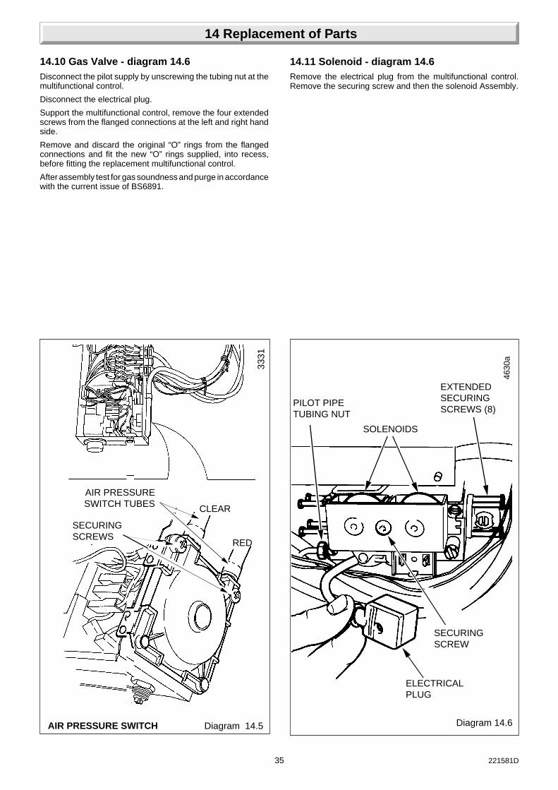
14.9 Air Pressure Switch: Diagram 14.5Remove the control box, refer to Section 9.
Disconnect the air pressure switch tubes.
Disconnect the electrical plug from the PCB, see diagram 14.3.
Remove the two securing screws to release the air pressureswitch and cable assembly.
Remove the cable assembly and fit to the replacement airpressure switch.
14 Replacement of Parts
35 221581D
14 Replacement of Parts
14.10 Gas Valve - diagram 14.6Disconnect the pilot supply by unscrewing the tubing nut at themultifunctional control.
Disconnect the electrical plug.
Support the multifunctional control, remove the four extendedscrews from the flanged connections at the left and right handside.
Remove and discard the original “O” rings from the flangedconnections and fit the new “O” rings supplied, into recess,before fitting the replacement multifunctional control.
After assembly test for gas soundness and purge in accordancewith the current issue of BS6891.
Diagram 14.5AIR PRESSURE SWITCH
AIR PRESSURESWITCH TUBES
RED
CLEAR
SECURINGSCREWS
3331
14.11 Solenoid - diagram 14.6Remove the electrical plug from the multifunctional control.Remove the securing screw and then the solenoid Assembly.
ELECTRICALPLUG
PILOT PIPETUBING NUT
EXTENDEDSECURINGSCREWS (8)
SECURINGSCREW
Diagram 14.6
4630
a
SOLENOIDS

36221581D
14.12 Fan: Diagram 7.2Gain access as described in the Servicing Section “HeatExchanger Cleaning”.
Fit new fan.
14.13 Main BurnerGain access as described in the servicing section and replacethe burner.
14.14 Main Burner InjectorGain access as described in the servicing section and replacethe main burner injector.
14.15 Insulation: Diagram 14.7Remove the inner case, see diagram 7.1.
Remove the combustion chamber front cover, see diagram 7.2.
Remove the screw securing the front insulation and slide out.
The side insulation panels can be removed by sliding themforward.
Pull the rear insulation panel forward off the retaining angle atthe bottom, allow the panel to drop, then slide the top of thepanel forward.
14.16 Heat Exchanger: Diagram 14.8Gain access as described in the servicing section for “HeatExchanger Cleaning”.
Drain the boiler circuit of water.
A drain point is provided for the draining of residual water fromthe heat exchanger.
Remove the retaining clip and thermostat phials as previouslydescribed in this section.
Disconnect the flow and return unions.
The heat exchanger can now be removed, on replacement usethe new sealing washers supplied and ensure the lugs on thecombustion chamber locate into the cutouts on the heatexchanger.
14 Replacement of Parts
Diagram 14.7INSULATION
COMBUSTIONCHAMBERFRONT COVER
3341
SIDE INSULATIONPANELS
INSULATIONSECURINGSCREW
REARINSULATIONPANEL
Diagram 14.8HEAT EXCHANGER
DRAINPLUG
LOCATINGLUG
UNION FLOW
3335

37 221581D
INNERCASESEAL
7887
PILOTVIEWINGWINDOW
INNERCASE
14.17 Pilot Viewing Window: diagram 14.10Remove the old self adhesive aluminium foil gasket and the oldmica window. Replace with a new mica window. Peel off thebacking paper and secure with new self adhesive aluminium foilgasket, see diagram 14.10. Ensure no air bubbles are trappedunderneath the foil.
ImportantMake sure that the mica window fully covers the opening andthat the hole in the aluminium foil gasket is centred overopening.
14.18 Inner Case Seal: diagram 14.9Remove the inner case.
When removing seal make sure that all the old adhesive isremoved.
When fitting the new seal make sure that it fits correctly and hasnot buckled.
14 Replacement of Parts
Diagram 14.9
Diagram 14.10
SELF ADHESIVEALUMINIUM FOILGASKET
7886OPENING
(BOILER INNERCASE FRONT)
MICA
PEEL OFFBACKINGPAPER

38221581D
15 Spare Parts
15.1 Part IdentificationThe key number in diagram 15.1 and the list will help to identifythe part.
15.2 OrderingWhen ordering any spare part please quote the part numberand description from the list. The model name and serialnumber of the appliance should also be quoted, they are locatedon the control box cover, see diagram 7.1.
If ordering from British Gas also quote the GC number of theappliance and part.
Key No. Part No Description GC Number
1 203374 Gas control assembly
2 203099 Injector - 30F 313 389
2 205700 Injector - 40F 313 387
2 230287 Injector - 50F 313 603
3 230357 Air pressure switch 313 604
4 230385 Pilot burner/electrode assembly
30F and 40F 387 159
4 230209 Pilot burner/electrode assembly
50F 387 980
5 WW4607 Ignition lead 136 824
6 800271 Thermostat - control 313 605
7 800272 Thermostat - overheat cutoff 313 606
8 800273 Fan assembly - 30F and 40F 313 607
8 800274 Fan assembly - 50F 313 608
9 800275 Thermostat knob assembly 313 609
10 202015 Fuse 334 750
11 Mica window and foil gasket
12 900817 Control board (PCB) 313 301

39 221581D
Diagram 15.1
1
8
11
4
3
9
5
7
1210
2
7904
15 Spare Parts
6

40221581D
11 Spare Parts
Because of our constant endeavour for improvement, details may vary slightly from those shown in these instructions.