
Glossary of Camshaft Related Terms - CARiD · PDF fileGlossary of Camshaft Related Terms ABDC:...
20
Glossary of Camshaft Related Terms ABDC: After Bottom Dead Center. ATDC: After Top Dead Center. BASE CIRCLE: The base of the cam lobe that is round and concentric with the journals (also known as the 'heel') BBDC: Before Bottom Dead Center BTDC: Before Top Dead Center CAM FOLLOWER: Usually a flat faced or roller companion to the camshaft that transfers the action of the camshaft to the rest of the valve train by sliding or rolling on the cam lobe surface. CAM LIFT: The distance that the cam raises the lifter. (not to be confused with 'valve lift”) CAM LUBE: A non-detergent lubricant containing Molybdenum-Disulphide which is spread on the cam lobes when installing a camshaft to prevent galling and insure protection during the critical break in period (the first 20 minutes of operation). CAM MASTER: After the design of the cam is computed, it is transferred to a precision template or master. The master
Transcript of Glossary of Camshaft Related Terms - CARiD · PDF fileGlossary of Camshaft Related Terms ABDC:...

Glossary of Camshaft Related Terms
ABDC:
After Bottom Dead Center.
ATDC:
After Top Dead Center.
BASE CIRCLE:
The base of the cam lobe that is round and concentric with the journals (also known as the 'heel')
BBDC:
Before Bottom Dead Center
BTDC:
Before Top Dead Center
CAM FOLLOWER:
Usually a flat faced or roller companion to the camshaft that transfers the action of the camshaft to therest of the valve train by sliding or rolling on the cam lobe surface.
CAM LIFT:
The distance that the cam raises the lifter. (not to be confused with 'valve lift”)
CAM LUBE:
A non-detergent lubricant containing Molybdenum-Disulphide which is spread on the cam lobes wheninstalling a camshaft to prevent galling and insure protection during the critical break in period (the first20 minutes of operation).
CAM MASTER:
After the design of the cam is computed, it is transferred to a precision template or master. The master

is then installed in the cam grinding machine to generate the shape of the lobes of the production cam.
CAM PROFILE:
The actual shape of the cam lobe.
CAMSHAFT:
A shaft containing many cams that convert rotary motion to reciprocating (lifting) motion. For every 2revolutions of the crankshaft, the camshaft rotates 1 revolution. The lobes on the camshaft actuate thevalve train in relation to the piston movement in an internal combustion engine. The camshaftdetermines when the valves open and close, how long they stay open and how far they open.
CHEATSTOCK CAM:
The improved stock cam has stock lift and sometimes stock duration (depending on the class rules) butthe flanks are modified so that they are faster acting. This process adds about a 5% increase in the areaunder the lift curve. This means there will be a power increase during the entire rpm range of theengine. This type of grind works very well in engines that have fuel injection systems that run off ofmanifold vacuum and are therefore very sensitive to camshaft duration changes.
CHILLED IRON LIFTER:
A cam follower made from high quality iron alloy that is surface hardened by pouring the molten iron intoa honeycomb mold with a chilled steel plate at the bottom resulting in a denser and harder lifter surface(compatible with steel and hard face overlay cams only).
CLEARANCE RAMPS:
The portion of the cam lobe just up off the base circle which lifts at a slower speed than the 'flank'. Itspurpose is to 'dampen' or ease the initial lifter motion rather than opening and closing suddenly. Rampson hydraulic lifter engines are very small, maybe only as high as .003” and only serve as noisereduction devices because the 'dampening' effect is mostly catered for by the hydraulic lifter. Ramps onsolid lifter camshafts are much higher, anywhere from .006” to .020” (ramp heightmultiplied by your rocker ratio equals your maximum valve clearance) Ramp designs have a tremendouseffect on power output and valve train reliability.
COIL BIND:
A valve spring that has been compressed to the point where the coils are stacked solid and there is nospace left between the coils. The valve cannot open any further when this happens.
CONCENTRIC:

Running true or having the same center. In camshaft terminology, the cam bearings and lobes areconcentric to each other when the cam is straight and there is .001" or less runout between all the camlobes and bearings.
CORE DIAMETER:
The diameter of the camshaft as measured between the cam lobes.
DURATION AT THE CAM:
Number of degrees measured at the cam from opening to closing (at a given checking height) E.G. on aKelford Cams cam card for a pushrod style engine we state cam duration figures at .050”checking height.
DURATION AT THE VALVE:
Number of degrees measured at the valve from opening to closing (at a given checking height) E.G. on aKelford Cams cam card for a Japanese over head cam engine we state valve duration figures at 1.00mmchecking height.
FLANKS:
The sides of the cam lobe or the portion of the lobe that lies between the nose and the clearance rampon either side.
FORGED:
A metal object which was formed under pressure, while in a red hot, or semi-molten state
HARDFACE OVERLAY:
A process to apply a tungsten carbide, chrome-nickel alloy to the outer surface of the cam lobe. Thesecombined alloys provide an extra-durable surface for the tremendous spring pressures and high rpm oftoday's all-out competition engines. Kelford Cams use 50HRC or 60 HRC hard weld rod, depending onthe application.
INDUCTION HARDENING:
A process of electrical heat treating whereby an object is placed inside a coil of heavy wire through whichhigh frequency current is passed. Through the electrical properties of this induction coil, the object insidethe coil becomes cherry red almost instantly and is then quenched in oil.
INERTIA SUPERCHARGING:
A condition created by the piston as it reaches the bottom of its intake stroke, by which the inertia of theintake air column continues to pack the cylinder until the pressure exceeds that of the atmosphere.
INTERFERENCE FIT:
In a dual spring combination where the outside diameter of the inner spring and the inside diameter ofthe outer spring nearly approximate each other so that there is a slight press fit between the 2 springs.This produces a dampening effect on valve spring vibration and surge.
LASH (VALVE LASH) / TAPPET CLEARANCE:
This is the clearance between the valve tip and the rocker or cam bucket (sometimes measured at thecam on over head cam engines) Kelford Cams spec cards state where this is to be measured andwhether to set the clearance hot or cold. Alloy block sprint car engines may have .015” clearancedifference from hot to cold, therefore these engines need high CLEARANCE RAMPS and need to be sethot. The lash is relevent to your particular camshaft (not to the engine type) and must be setcorrectly so as not to run off the end of the 'CLEARANCE RAMP.
LIFT CURVE:
By installing the camshaft in a block or head, you can plot the lift of the cam in relation to each degree ofcamshaft rotation by installing a dial indicator on the valve retainer and a degree wheel on thecrankshaft. All that is necessary is to rotate the crankshaft every 2 degrees and take a reading on thedial indicator at each of these intervals and transfer the readings to an Excel spreadsheet to produce agraph of the lift curve, from there you can deduce velocity, acceleration and jerk, to analyze the valvemotion.
LOBE:
The lobe is eccentric to the cam bearings of the camshaft and transmits a lifting motion through thevalve train to operate the valves. The design of the lobe determines the usage of the camshaft.
LOBE CENTERS-CAM:
The distance measured in degrees between the centerline of the intake lobe and the centerline of theexhaust lobe in the same cylinder.
LOBE TAPER:
This is the amount by which the diameter of the front of the base circle is different from the diameter ofthe rear of the base circle. The amount of taper can be anywhere from zero to .003" depending on theengine. If the forward side of lobe is greater than the rear side we say that the cam has taper left . If theback side of the lobe is greater than the front side then we say that the cam has taper right . Lobe taperhas a dramatic effect on the speed of rotation of the lifter. If the lifter does not rotate at the properspeed, premature lifter and cam wear will occur.

NET VALVE LIFT:
The actual lift of the valve. This lift can be determined by multiplying cam lift by rocker ratio andsubtracting valve clearance (lash) if any.
NITRIDING:
Gas nitriding is a surface heat treatment which leaves a hard case on the surface of the cam. This hardcase is typically twice the hardness of the core material up to .010" deep. This process is accomplishedby placing the cam into a sealed chamber that is heated to approximately 950 degrees F and filled withammonia gas. At this temperature a chemical reaction occurs between the ammonia and the cam metalto form ferrous nitride on the surface of the cam. During this reaction, diffusion of the ferrous-nitride intothe cam occurs which leads to the approximate .004" case depth. The ferrous-nitride is a ceramiccompound which accounts for its hardness. It also has some lubricity when sliding against other parts.The nitriding process raises and lowers the chamber temperature slowly so that the cam is not thermallyshocked. Because of its low heat treat temperature no loss of core hardness is seen. Gas nitriding wasoriginally conceived where sliding motion between two parts takes place repeatedly so is thereforedirectly applicable to solving camshaft wear problems.
NORMALLY ASPIRATED:
An engine that utilizes either carburetors or fuel injection, without a mechanical device that forces thefuel/air mixture into the combustion chambers (non-supercharged).
NOSE OF THE LOBE:
The highest portion of the cam lobe from the base circle (full lift position).
OHC:
Overhead cam engine. In this type of engine the camshaft is positioned above the valves. DOHC, doubleover head cam, SOHC, single over head cam.
OHV (PUSHROD ENGINES):
Overhead valve engines. In this type of engine the camshaft is positioned beneath the valves. (i.e. 350c.i. Chevrolet V8, Nissan A12 etc)
OVERLAP:
A situation where both the intake and exhaust valves are open at the same time when the piston is attop dead center on the exhaust stroke. The greater the seat duration is on the intake and exhaust lobes,and the tighter the LOBE SEPARATION, the greater the overlap will be (measured in degrees ofcrankshaft rotation)

PARKERIZING:
A thermo-chemical application whereby a nonmetallic, oil-absorptive coating is applied to the outsidesurface of the camshaft. This helps initial break-in without scuffing the cam lobes.
PRE-LOAD:
To load before applying a different load for example setting a hydraulic lifter beyond zero clearance intopreload by a set amount
PROFERAL IRON:
A very high quality cast iron alloy. Used primarily for camshafts because of its excellent wearing ability.
ROLLER TAPPET:
The roller tappet performs the same function as the mechanical or hydraulic tappet. However, instead ofsliding on the cam face, the lifter contains a roller bearing which rolls over the cam surface.
SEAT DURATION:
The total time (measured in degrees of crankshaft rotation) that the valve is off of its valve seat fromwhen it opens until when it closes.
SPLIT OVERLAP:
An occurrence when both the intake valve and the exhaust valve are off their seats at the same time bythe same amount at TDC.
SPRING FATIGUE:
Valve springs have a tendency to lose their tension after being run in an engine for certain periods oftime, because of the tremendous stress they are under. At 6,000 rpm, for example, each spring mustcycle 50 times per second. The tremendous heat generated by this stress eventually effects theheat-treating of the spring wire and causes the springs to take a slight set (drop in pressure).
SPRING SURGE:
The factor which causes unpredictable valve spring behavior at high reciprocating frequencies. It'scaused by the inertia effect of the individual coils of the valve spring. At certain critical engine speeds,the vibrations caused by the cam movement excite the natural frequency characteristics of the valvespring and this surge effect substantially reduces the available static spring load. In other words, theseinertia forces oppose the valve spring tension at critical speeds.

SWEEP:
The amount of travel the cam lobe has across the lifter face. Lifter diameter determines flank velocity.
VALVE BOUNCE:
When there is a lack of valve spring tension, or where a poorly designed cam having excessivedeceleration and velocity characteristics is used, the valve lands with such force on the valve seat that ithas a tendency to bounce back up again, causing a loss of power and resulting in harmful damage
VALVE EVENTS:
The opening and closing points of the valve with relation to the crankshaft.
VALVE FLOAT:
A detrimental condition caused by poor cam design mis-matched components, over revving the engine,or by inadequate valve spring open pressure, resulting in a lag of the valve gear components where theyfail to follow the the cam profile.
VALVE LASH:
Same as VALVE CLEARANCE or TAPPET CLEARANCE, necessary to allow for thermal expansion of thevalve train components during operation.
VALVE TRAIN:
The components or train of parts used to operate the valves in conjunction with the cams.

Kelford Cams Flat Tappet Camshaft Break-in Procedure
Prior to installation:
Check the compatibility of the camshaft with the remainder of the valve train components, particularlythe valve springs.
On high load spring applications you will need to use lighter load springs, or alternatively remove theinner spring (for dual spring applications) just for break-in.
The most critical time in the life of a flat tappet camshaft is the first 20 minutes of break in, during whichtime the bottoms of the tappets mate-in with the cam lobes.
This is true for both hydraulic and mechanical flat tappet camshafts.
Due to some country's environmental regulations, some of today's oils are missing or have lower levelsof the critical ingredients needed for flat tappet camshaft break in. Therefore choose your motor oilcarefully as some engine oils are not suitable.
Prior to installing the camshaft and lifters, it is recommended that the crankcase be drained and filledwith new, clean oil, as aforementioned. The oil filter should also be changed at this time. Proper flattappet camshaft break-in starts with the cam installation and includes the following steps:
Before installing the camshaft and lifters you must wash them thoroughly in clean mineral spirits toremove the rust preventative that is placed on the cam prior to shipping. NOTE: As a "rule of thumb",always thoroughly clean any part before installing it in an engine. Never "assume" that the parts arecleaned before packaging.
WARNING: NEW LIFTERS MUST BE INSTALLED WITH YOUR NEW CAMSHAFT
Installation Procedure
DO NOT "pump-up" hydraulic lifters before use. This can cause the lifters to hold a valve open duringengine cranking, resulting in low compression. The low compression will delay engine start-up and isvery detrimental to proper camshaft "break-in".
With the supplied moly paste lube, coat the bottom of the lifters, cam lobes and distributor gear.
Set your valve lash or lifter preload. Try to minimize the number of times that you rotate the engine, asthis can displace the moly paste from the lobes and lifters.
If possible prime the oiling system. When priming, rotate the engine at least one complete revolution toassure oil gets to all valve train components.
Valve covers should be off to assure that all rockers are oiling.

Preset the ignition timing to start the engine at a fast idle. It is important that the static ignition timing isas close as possible and if the engine has a carburetor, it should be filled with fuel. The engine needs tostart quickly without excessive cranking to insure immediate lubrication to the cam lobes.
Start the engine and immediately bring to 2,500 rpm. Timing should be adjusted, as closely as possible,to reduce excessive heat or load during break-in. Get the engine running fairly smoothly and vary theengine speed from 1500-3000 RPM in a slow acceleration/deceleration cycle. During this time, be sure tocheck for any leaks and check out any unusual noises. If something doesn't sound right, shut the engineoff and check out the source of the noise. Upon restart, resume the high idle speed cycling. Continue thevarying "break-in" speed for 20 - 30 minutes. This is necessary to provide proper lifter rotation toproperly mate each lifter to its lobe. Should the engine need to be shut down for any reason, uponre-start it should be immediately brought back to 3000 rpm and the break-in continued for a total runtime of 20 - 30 minutes.
Let the engine cool, and then drain the crankcase and properly dispose of the oil and oil filter. Refill thecrankcase with premium oil. At this point the initial "break in" is complete. You can drive the vehicle inyour normal manner. We recommend changing the oil and filter after 1,000 kms.
Additional Information
Spring Pressures: For extended camshaft life, flat-tappet cams should not be run with more than therecommended open valve spring pressure. Racing applications will often need to run more springpressure at the expense of reduced camshaft life. In order to "break-in" a camshaft with high openpressures, the inner springs should be removed to reduce "break-in" load. The inner springs can then bereinstalled after initial "break-in" is complete.
Lifter Rotation: Flat tappet cams (both hydraulic and mechanical) have the lobes ground on a slight taperand the lifter appears to sit offset from the lobe centerline. This will induce a rotation of the lifter on thelobe. This rotation draws oil to the mating surface between the lifter and the lobe. If it is possible to viewthe pushrods during "break-in", they should be spinning as an indication that the lifter is spinning. If youdon t see a pushrod spinning, immediately stop the engine and find the cause.
Never use old flat tappet lifters on a new cam. On flat tappet cams, the lobes and lifter bottoms matetogether and if the lifters are removed from the engine, they must go back on the same lobe from whichthey were removed. Kelford Cams recommends the use of high quality tappets to prevent prematurecam or lifter wear. This is the reason that we prefer to sell you a cam and lifter kit, this way you knowthat you are buying a 'matched set' and risk of failure during break in is greatly reduced.

Checking Piston to Valve Clearance
When you install a high performance cam, it is possible that there may not be sufficient clearancebetween valves and pistons when near TDC on overlap. Even if they don't touch when you rotatethe crankshaft slowly by hand, they may hit and damage the engine at high revs due to slight "Floating"of the valves, stretch in the rods, deflection in the valve train, and other causes.
We recommend at least .080" clearance between intake valves and pistons at all times, and at least.100" for exhaust valves, which expand more with heat. Add .030" to these figures if you have aluminumrods in the engine to allow for their expansion and stretch.
If you are using aftermarket heads, many of them have modified valve positions and/or valve angles.This may cause valve to piston valve relief alignment problems. If your engine is equipped with anaftermarket head of this type, we recommend checking piston to valve over a broader range. The easiestway of checking piston to valve clearance in an engine, with the cylinder heads installed, is to install apair of light checking springs in place of the valve springs. These light checking springs will allow you todepress the valve easily at any time during the entire rotation of the engine, enabling you to measurethe piston to valve clearance.
If you are going to use rocker arms with a higher than stock rocker ratio now or in the future, you willneed to check piston to valve clearance with the higher ratio rocker at this time. (Higher ratio rockersincrease gross valve lift). After the light checking springs are installed in place of the standard valvesprings, install the rocker arms and then adjust valve lash to zero, zero lash will work best to give youflexibility if at any time you want to tighten or loosen lash to change performance characteristics, andyou'll know that you have sufficient clearance.
Be absolutely certain that you use the correct type of lifter for the camshaft that is being checked. Thismeans a flat tappet for a mechanical or hydraulic cam (do not use a hydraulic lifter, as the plunger canmove), or a mechanical roller tappet for a roller camshaft. Remember; always use a flat tappet lifter on aflat tappet cam and a roller lifter on a roller cam. As a general rule, the closest point of piston to valveclearance during the rotation of an engine is between 15 degrees and 5 degrees before top dead centeroverlap for the exhaust valve and between 5 degrees and 15 degrees after top dead center overlap forthe intake valve. This sequence takes place during the overlap cycle when both valves are open, 360degrees from the top dead center compression stroke.
With your degree wheel still mounted to the engine in correct TDC position, and the valves adjusted tozero lash, turn the engine in its normal direction of rotation until you come to 15 degrees before topdead center overlap on your degree wheel, then set the tip of the dial indicator on the exhaust valvespring retainer, in line with the movement of the valve. (Figure 8) Preload the dial indicator to about themid-point of travel, and set to zero. Depress the valve with your finger by pressing on the valve end ofthe rocker arm until the exhaust valve contacts the piston, make a note of the reading on the dialindicator, and record the clearance. Now, continue turning the engine in its normal direction two degreesat a time, checking and recording the clearance every two degrees until you reach top dead center, onyour 7 4/00 803 Figure 8. Degree wheel. Remember, since the valve will be moving, the dial indicatorwill not return to zero. You can either subtract the difference or reset the dial indicator back to zero eachtime before you make your clearance check.

piston to valve clearance will depend on how far advanced or retarded your cam is. Remember, as youadvance your cam you will lose intake piston to valve clearance and as you retard your cam you will loseexhaust piston to valve clearance.
Move the dial indicator to the intake retainer and start checking the intake piston to valve clearance thesame way you checked the exhaust, except begin at top dead center and continue to 15 degrees aftertop dead center, turning the engine in its normal direction of rotation. The actual position of closest

The Sole Purpose of Degreeing Your Cam
Is to achieve the correct valve opening and closing points for your engine.
All of our new camshafts are ground to exact specification using the latest CNC machining processes butthere are other factors that can cause incorrect camshaft to crankshaft phasing. Such as:
Cam or crank gears are incorrectly marked.
Keyways are out of position on gears.
Keyway in the crankshaft is miss-indexed.
On SOHC & DOHC engines, milling the head or the block will retard the cam(s)
On SOHC rocker arm style engines, valve tip length, rocker geometry and base circle size will effect lobeseparation, therefore effecting valve events.
Thus properly degreeing your cam is essential.
Before You Start To Degree Your Cam
Assuming that you have carried out all of the preliminary static measurements and clearance checks forvalve to valve, valve to piston, retainer to stem seal, cam to head casting, cam to con-rod, spring seatpressure, distance to coil bind at full lift etc, all parts are clean, and lightly oiled you are ready to startdialing in your camshaft.
The best place to start is to install your cam on factory marks using the engine manufacturer'sprocedure.
Lifter Setup Instructions
Be absolutely certain that you use the correct type of lifter for the camshaft that is being Degreed.Hydraulic lifters must never be used when degreeing cams, they can bleed down and give you falsereadings.
For Pushrod style engines this is easy, if your camshaft choice is hydraulic roller or hydraulic flat tappet,simply purchase a solid equivalent of your lifter. Install a pushrod that has an oil hole in it, so that the tipof the dial indicator locates properly in the end of the pushrod.
For over head cam engines that have hydraulic cam buckets, such as Nissan RB20 or Suzuki G13B or forover head cam engines with rocker arms and hydraulic lifters, such as Mitsubishi 4G63 or Nissan SR20,you will need to make a solid lifter that gives 0.1mm valve clearance when the cam is on the base

circle. This is easiest done by pulling the plunger out of a hydraulic lifter and replacing it with apiece of turned silver steel (or similar) that sits properly inside the lifter body and is shaped at the valveend to clear the retainer and give a perfect flat contact to the valve tip.
(Remember to take it back out once you are done and put the proper hydraulic lifter back in)
EQUIPMENT REQUIRED to properly degree your camshaft
1. Degree wheel2. Metric or imperial dial indicator and method of mounting it to the head or block3. Positive stop TDC finding tool (either the spark plug type or a block mounted type)4. Rigidly mounted pointer to indicate degree wheel position
Mounting the Degree Wheel
Attach the degree wheel to the flywheel or to the front pulley of the engine ensuring that you still have amethod of manually rotating the engine.
Attach the pointer to the engine ensuring that it is rigid and won't move if you accidentally bump it.
Finding Top Dead Center (TDC)
Rotate the crankshaft until you get number one piston as close as possible to TDC. Next, adjust yourpointer to the zero TDC position on the degree wheel.
It is essential at this point that you have some means of rotating the crank that will not interfere withthe degree wheel. The crank can be rotated from either the front or the flywheel end. The greater theleverage, the smoother you can rotate the crank for timing checks. (Do not use the starter for turningthe engine while degreeing).
Now that the Degree Wheel has been set at approximate TDC, and a means for turning the crankprovided, you're ready to install and set the piston stop.
Turn the crankshaft (in the normal direction of rotation) to lower the piston enough in the cylinder tomove the degree wheel 15-20 degrees, screw in the piston stop until it contacts the piston, Turn theengine in the normal direction of rotation until the piston comes back up and touches the piston stop.
Make a note of what degree the pointer is on the degree wheel.
Turn the engine in the opposite direction until the piston comes back up and touches the piston stopagain.
Make a note of what degree the pointer is on the degree wheel.
Add these two numbers together then divide them in half. For example: Let's say that the stop pointsare 16° in one direction and 20° in the opposite direction. The total would be 36 degrees. Thisfigure divided in half would be 18 degrees. Therefore 18 degrees from either of your stop points is truetop dead center.
Now either move the pointer to align with the 18 degree mark on the degree wheel, or carefully loosenthe degree wheel (without disturbing the position of the crankshaft) and move the degree wheel to the18 degree mark, making sure that the piston is still against the stop.
Always double check measurements and readings. Repeat the procedure above until you get the sameamount of degrees on both sides of TDC. Remove your piston stop and you are ready to properly degreeyour cam.
Mounting the Dial Gauge
For pushrod style engines mount the dial gauge to something solid that won't flex or move.
Install a pushrod that has an oil hole in it as this will properly locate the tip of the dial indicator.
It is important that the indicator plunger be aligned as closely as possible with the lifter being measured,any substantial angle between the axis of the plunger and the lifter will introduce geometrical errors intothe lift readings.
With the cam on the base circle set the dial gauge to zero with enough preload that the gauge is held

firmly but not so much preload that you bind the gauge on full lift.
Rotate the engine slowly in the proper direction of rotation and make sure that the dial gauge movesfreely up and over full lift and back to the zero position. If it doesn't return to zero, there are severalpossible causes:
the dial indicator may not be mounted rigidly
the lifter may not be contacting the base circle properly
the lifter could be sticking slightly in its bore.Find the trouble and correct it before proceeding.
Cam Specification Card
All the information you need for checking valve timing of your engine is provided on the specificationcard that you receive with your new Kelford cam. This will include the opening and closing timing pointsand the amount of lift at the lifter or at the valve (depending on engine type) at which the timing shouldbe checked. It will include Cam lift, rocker ratio, Net valve lift, valve lash (tappet clearance) and more.
The Correct Method
The method we use below is the correct method to accurately degree your cam to achieve the propervalve opening and closing events.
We have split the method into two engine types to give proper examples. Pushrod engines and Overhead cam engines.
Pushrod Engines
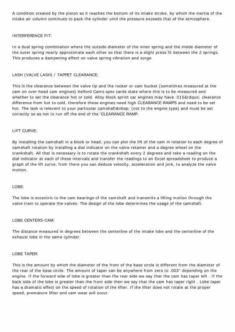
Using the intake opening and closing at .050" cam lift, obtained from the information on your cam speccard, turn the engine in the normal direction of rotation. Watch the dial indicator. When it moves up.050", stop rotating the engine.
Record the degree wheel number that the pointer is on. (In our example spec card 'A' it is 24°BTDC).
Continue to rotate the engine in the same direction. Watch the dial indicator; it will change direction atmaximum lobe lift. Record the cam lobe lift, this should match the cam lift figure on your spec card(.350" in the example of Spec card 'A').
Continue to rotate the engine in the same direction (counting down) until you are .050" before closing.Again record the degree wheel number that the pointer is on. (In example 'A' it is 56° ABDC)
Continue down to zero lift and verify that the dial indicator has returned to zero. The opening and closingfigures should be within ±1 degree.
At this point we check the duration and centerline by adding the Intake Opening (IO) point before TDC
plus 180 degrees of crank rotation to get us to BDC plus the Intake Closing (IC) point in degrees ABDCso using the figures on spec card 'A' we calculate as follows, 24+180+56 = 260 degrees of intakeduration at .050" cam lift. This figure should match the duration figure on your spec card, 260 degreesdivided by two less the intake opening gives you the centerline number that should match your spec carde.g.; 260/2-24=106degrees ATDC.
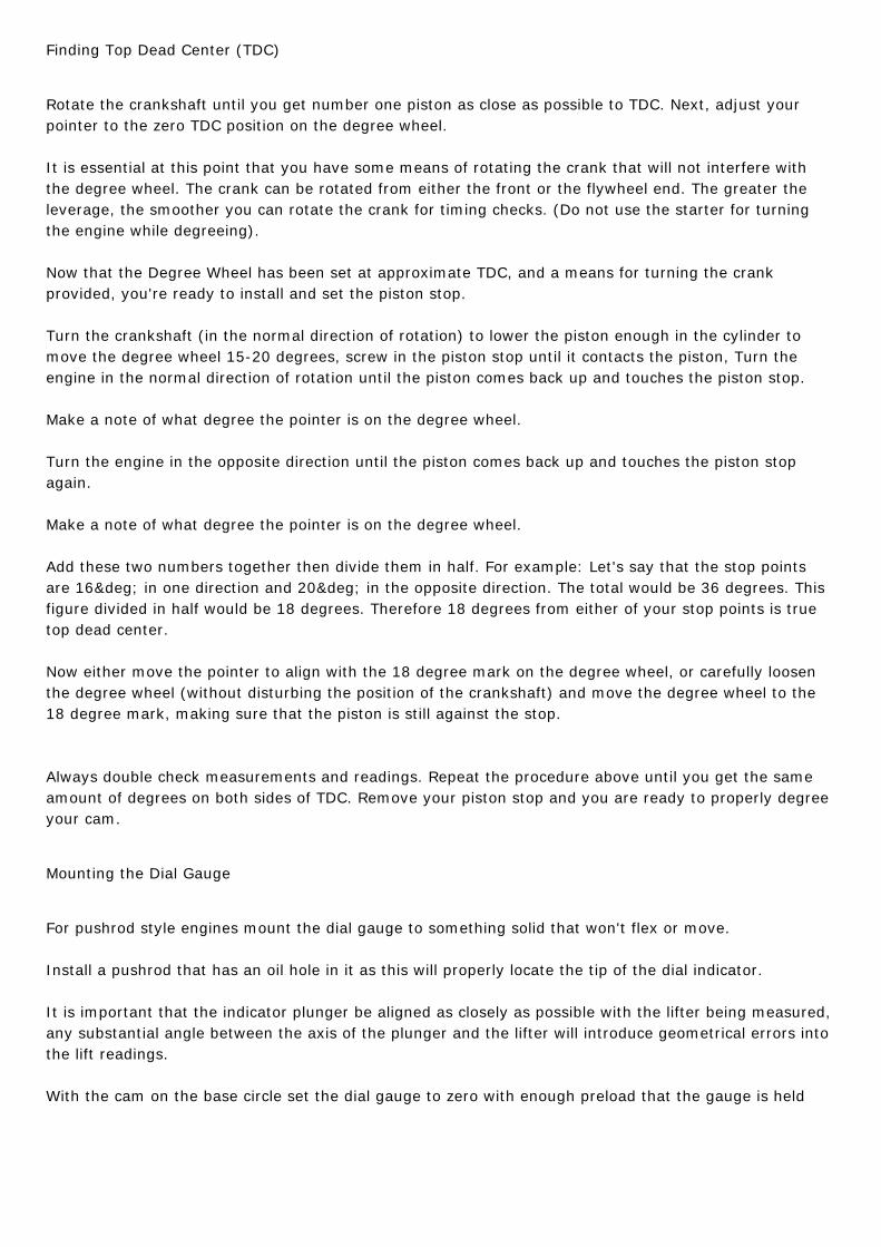
If the camshaft has a short duration and / or late valve events like the one in the example spec card 'B",the Intake Opening point could be ATDC in which case the equation to find duration is: 180 degrees fromTDC to BDC, less the Intake Opening point in degrees ATDC plus the Intake Closing point in degreesABDC. For example 'B' Inlet Opens 5 degrees ATDC, Inlet Closes 45 degrees ABDC the equation is180-5+45=220 degrees of cam duration at .050" cam lift.

To find the centerline figure the equation is: Duration divided by two, plus the Inlet Opening pointexample 'B' would then be: 220/2+5= 115 degrees ATDC centerline. If the duration matches but thecenterline figure and open and close events do not, you will need to advance or retard the cam toachieve the correct result.
Go through the procedure again until you are within one degree of where you want to be (preferably onthe advanced side if anything to allow for chain / belt stretch during operation).
Depending on the engine being used, there are usually offset bushings, offset keys, or multi-indexedgears to accomplish this movement.
Once you are happy, move to the exhaust and repeat the process. Using spec card A we have anExhaust Opening (EO) of 63 degrees BBDC and an Exhaust Closing (EC) of 27 degrees ATDC, theequation is 63+27+180 = 270 degrees of exhaust duration at .050" cam lift, to find the centerline as adouble check, the formula is duration divided by two less exhaust opening; 270/2-27 = 108 degreesBTDC. If your intake is set correctly the exhaust should match the spec card as well unless there is avariation in the separation.
To find separation, simply add the intake and exhaust centerline and divide by two.
As a triple check, measure the valve lift at TDC, and this should also match the card.
Once you are happy with the cam timing, you are ready to final check valve to piston clearance. (See Vto P instruction)
Single and Double Over Head Cam Engines
For these types of engines, Kelford Cams spec cards list duration, opening and closing events at thevalve (unless otherwise stated by us)
The setup procedure is the same as listed above except that the dial gauge will often need a longextension to reach down beside the cam lobe to contact either the spring retainer (in the case of a rockerarm engine) or the cam bucket (in the case of a direct bucket OHC engine)
For mechanical lifter over head camshafts all readings are taken with the valve lash set to the properclearance as specified by the cam card.
For hydraulic lifter over head camshafts, use a mechanical lifter for checking and set clearance to zero(remember to replace the checking lifter with the proper lifter once all checking is complete).
Turn the engine in the direction of rotation until you reach 1.00mm valve lift on the dial indicator, recordthe figure on the degree wheel, continue to rotate in proper direction counting up to full valve lift.
Record the full valve lift figure; this should match the figure on your spec card. Continue to rotate inproper direction, counting down from full lift until you are 1.00mm away from fully closed, record thedegree wheel figure.

As an example spec card 'C' gives an Intake Valve Opening (IVO) of 4 degrees BTDC and Intake ValveClosing (IVC) of 46 degrees ABDC.
To find duration, the formula is IVO of 4 degrees BTDC plus 180 degrees to get to BDC plus 46 degreesto the IVC point ABDC; 4+180+46 = 230 degrees of duration at the valve at 1.00mm checking height.
Use this formula to check that your measured duration matches your spec card.
The formula to find the centerline of the intake in example 'C' is, duration divided by two less IVO;230/2-4 = 111 degrees ATDC, this should match the figure on your spec card, if it doesn't you will needto advance or retard the cam and repeat the procedure until it is correct.
Once you are happy, move to the exhaust and repeat the process. Using spec card C we have anExhaust Valve Opening (EVO) of 38 degrees BBDC and an Exhaust Valve Closing (EVC) of 2 degrees

BTDC, the equation is 38+180-2 = 216 degrees of exhaust duration at 1.00mm valve lift.
To find the centerline as a double check, the formula is duration divided by two plus exhaust opening;216/2+2 = 110 degrees BTDC.
If the camshaft has a short duration and / or late valve events like the one in the example spec card 'D",the Intake Opening point could be ATDC in which case the equation to find duration is: 180 degrees(from TDC to BDC), less the Intake Opening point in degrees ATDC plus the Intake Closing point indegrees ABDC.
For example 'D' Inlet Opens 8 degrees ATDC, Inlet Closes 38 degrees ABDC the equation is180-8+38=210 degrees of duration at 1.00mm valve lift.
To find the centerline figure the equation is: Duration divided by two, plus the Inlet Opening pointexample 'D' would then be: 210/2+8= 113 ATDC centerline.
Once you are satisfied that the intake is correct move to the exhaust and repeat the process. Using speccard D we have an Exhaust Opening (EO) of 46 degrees BBDC and an Exhaust Closing (EC) of 8 degreesBTDC, the equation is 180-8+46 = 218 degrees of exhaust duration at 1.00mm valve lift, to find thecenterline as a double check, the formula is duration divided by two plus exhaust opening; 218/2+8 =117 degrees BTDC.
As a triple check, measure the valve lift at TDC, and this should also match the card.
Other valuable info:
Overlap at 1.00mm valve lift from Spec card 'C' = IVO of 4 degrees BTDC less 2 degrees BTDC = 2degrees at 1.00mm valve lift.
To find total overlap, check valve timing at 0.1mm valve lift as a checking height, if the valve motion issymmetrical at that lift, our example spec card cam which has a intake duration of 270 degrees and anexhaust duration of 256 degrees at 0.1mm will have valve timing events of IVO 24 BTDC / IVC 66 ABDC- EVO58 BBDC / EVC 18 ATDC giving an overlap of 24+18= 42 degrees.
Because of camshaft ramp designs the valve events at a lift as low as 0.1mm are often asymmetrical thisis why we specify checking valve timing at 1.00mm or .050" (in the case of imperial engines), it is moreaccurate for most people.
The Incorrect Method / Myths About the Centerline
Never use the 'centerline' method that zeros somewhere near full lift and then splits the differencebetween two readings on the degree wheel either side etc, this is not accurate.
The full lift position is not relevant to the engine it is only a quick reference figure used in dialogueamongst engine builders. Incoming intake charge or outgoing exhaust does not care where thecenterline is, they only respond to filling or evacuating the cylinder based on relevant valve opening andclosing events.
It is not accurate to use the centerline number to determine valve events.
It is accurate to use the valve event figures to determine a centerline number.
The problem with the centerline method is it has you finding the theoretical point of peak lift in relation

to crank rotation. This method makes the assumption that the lobe or valve motion you are checking issymmetrical; with its opening side being the exact same shape as the closing side of the lobe. Mostmodern cam lobes are asymmetrical, with the opening side of the lobe being much more aggressive andthe closing side being gentler. Therefore when you attempt to locate the middle (or centerline) of theasymmetrical lobe there is an automatic error. It could be as little as 2° or as much as 6°depending on the actual lobe design. Also, the centerline method does not really indicate if yourcamshaft was properly produced, as no confirmation of the duration at any given point. Our method willverify correct valve opening and closing and duration.