GloBug MODEL GB114BC - Multiquip Inc · · 2013-08-05GloBug MODEL GB114BC LIGHTING SYSTEM ......
66
OPERATION & PARTS MANUAL Revision #3 (03/22/06) THIS MANUAL MUST ACCOMPANY THE EQUIPMENT AT ALL TIMES. GloBug MODEL GB114BC LIGHTING SYSTEM (FOR USE WITH MQ SERIES GENERATORS)
Transcript of GloBug MODEL GB114BC - Multiquip Inc · · 2013-08-05GloBug MODEL GB114BC LIGHTING SYSTEM ......

OPERATION & PARTS MANUAL
Revision #3 (03/22/06)
THIS MANUAL MUST ACCOMPANYTHE EQUIPMENT AT ALL TIMES.
GloBugMODEL GB114BC
LIGHTING SYSTEM(FOR USE WITH MQ SERIES GENERATORS)

PAGE 2 — GLOBUG LIGHTING SYSTEM — OPERATION & PARTS MANUAL — REV. #3 (03/22/06)

GLOBUG LIGHTING SYSTEM — OPERATION & PARTS MANUAL — REV. #3 (03/22/06) — PAGE 3
HERE'S HOW TO GET HELPPLEASE HAVE THE MODEL AND SERIAL
NUMBER ON-HAND WHEN CALLINGMULTIQUIP CORPORATE OFFICE18910 Wilmington Ave. 800-421-1244Carson, CA 90746 FAX: 310-537-3927Email: [email protected]: www.multiquip.com
PARTS DEPARTMENT800-427-1244 FAX: 800-672-7877310-537-3700 FAX: 310-637-3284
MAYCO PARTS800-306-2926 FAX: 800-672-7877310-537-3700 FAX: 310-637-3284
SERVICE DEPARTMENT800-478-1244 FAX: 310-537-4259310-537-3700
TECHNICAL ASSISTANCE800-478-1244 FAX: 310-631-5032
WARRANTY DEPARTMENT800-421-1244, EXT. 279 FAX: 310-537-1173310-537-3700, EXT. 279
© COPYRIGHT 2004, MULTIQUIP INC.
Multiquip Inc, the MQ logo are registered trademarks of Multiquip Inc. and may not be used, reproduced, or altered without writtenpermission. All other trademarks are the property of their respective owners and used with permission.
This manual MUST accompany the equipment at all times. This manual is considered a permanent part of the equipment and shouldremain with the unit if resold.
The information and specifications included in this publication were in effect at the time of approval for printing. Illustrations arebased on the GloBug Lighting System. Multiquip Inc. reserves the right to discontinue or change specifications, design or theinformation published in this publication at any time without notice and without incurring any obligations.
To find the latest revision of thispublication, visit our website at:
www.multiquip.com

PAGE 4 — GLOBUG LIGHTING SYSTEM — OPERATION & PARTS MANUAL — REV. #3 (03/22/06)
TABLE OF CONTENTS
Specification and part numberare subject to change withoutnotice.
NOTE
MQ GLOBUG LIGHTINGMQ GLOBUG LIGHTINGMQ GLOBUG LIGHTINGMQ GLOBUG LIGHTINGMQ GLOBUG LIGHTINGSYSTEMSYSTEMSYSTEMSYSTEMSYSTEMHere's How To Get Help ............................................ 3Table Of Contents ..................................................... 4Parts Ordering Procedures ....................................... 5Safety Message Alert Symbols .............................. 6-7Rules For Safe Operation .................................... 8-11Operation and Safety Decals ............................. 12-14Specifications .......................................................... 15Dimensions ............................................................. 16Floodlight Footcandle Plots (BAL-120 STD.) .......... 17Floodlight Footcandle Plots (BAL-120R REF.) ........ 18Floodlight Footcandle Plots (BAL-115D REF.) ........ 18General Information ................................................ 20Components ....................................................... 22-23Pre-Setup ........................................................... 24-25Pre-Setup/Operation ............................................... 26Shutdown ................................................................ 27Maintenance ...................................................... 28-37Troubleshooting (Lamps) ........................................ 38Schematic Diagram................................................. 39Explanation Of Codes In Remarks Column ............ 40Suggested Spare Parts ........................................... 41
COMPONENT DRACOMPONENT DRACOMPONENT DRACOMPONENT DRACOMPONENT DRAWINGSWINGSWINGSWINGSWINGSNameplate and Decals ....................................... 42-43T-Handle Assy. ................................................... 44-45Steering Assy. .................................................... 46-47Outrigger Assy. .................................................. 48-49Mast Adapter Assy. ............................................ 50-51Main Mast Assy. ................................................. 52-53Mast Section Assy. ............................................. 54-55Baseplate Cover Assy. ....................................... 56-57Ballast Box Assy. ................................................ 58-59Fan Blower/Lamp Base Assy. ............................ 60-61Balloon/Lamp Guard Assy. ................................ 62-63
Terms and Conditions Of Sale — Parts .................. 64

GLOBUG LIGHTING SYSTEM — OPERATION & PARTS MANUAL — REV. #3 (03/22/06) — PAGE 5
When ordering parts,please supply the following information:
❒❒❒❒❒ Dealer account number❒❒❒❒❒ Dealer name and address❒❒❒❒❒ Shipping address (if different than billing address)❒❒❒❒❒ Return fax number❒❒❒❒❒ Applicable model number❒❒❒❒❒ Quantity, part number and description of each part❒❒❒❒❒ Specify preferred method of shipment:
✓ FedEx or UPS Ground✓ FedEx or UPS Second Day or Third Day✓ FedEx or UPS Next Day✓ Federal Express Priority One✓ DHL✓ Truck
Direct TOLL-FREE accessto our Parts Department:
Toll-free nationwide — 800-427-1244
Toll-free FAX — 800-6-PARTS-7 (800/672-7877)
MULTIQUIP INC.18910 WILMINGTON AVENUEPOST OFFICE BOX 6254CARSON, CALIFORNIA 90749310-537-3700 • 800-421-1244FAX: 310-537-3927E-MAIL: [email protected]: www.multiquip.com
Here’s how to get help...Please have the model and serial numberon hand when calling.
MULTIQUIP CORPORATE OFFICE18910 Wilmington Ave. 800-421-1244Carson, CA 90746 FAX: 310-537-3927Email: [email protected]: www.multiquip.comPARTS DEPARTMENT800-427-1244 FAX: 800-672-7877310-537-3700 FAX: 310-637-3284MAYCO PARTS800-306-2926 FAX: 800-672-7877310-537-3700 FAX: 310-637-3284SERVICE DEPARTMENT800-421-1244 FAX: 310-537-4259310-537-3700TECHNICAL ASSISTANCE800-478-1244 FAX: 310-631-5032WARRANTY DEPARTMENT800-421-1244, EXT. 279 FAX: 310-537-1173310-537-3700, EXT. 279
PARTS ORDERING PROCEDURES
Note: Unless otherwise indicated by customer, allorders are treated as “Standard Orders”, and willship within 24 hours. We will make every effort to ship“Air Shipments” the same day that the order isreceived, if prior to 2PM west coast time. “StockOrders” must be so noted on fax or web forms.
Extra Discounts!All parts orders which include complete part numbers andare received by our automated web parts order system, orby fax qualify for the following extra discounts:
Ordered Standard Stock ordersvia orders ($750 list and above)
Fax 3% 10%
Web 5% 10%
Special freight allowanceswhen you order 10 or moreline items via Web or Fax!**FedEx Ground Service at no charge for freightNo other allowances on freight shipped by any other carrier.**Common nuts, bolts and washers (all items under $1.00list price) do not count towards the 10+ line items.
Place Your Parts Order Via Web or FaxFor Even More Savings!
(Domestic USA Dealers Only)
NOTE: DISCOUNTS ARE SUBJECT TO CHANGE

PAGE 6 — GLOBUG LIGHTING SYSTEM — OPERATION & PARTS MANUAL — REV. #3 (03/22/06)
Safety precautions should be followedat all times when operating thisequipment. Failure to read andunderstand the Safety Messages andOperating Instructions could result ininjury to yourself and others.
FOR YOUR SAFETY AND THE SAFETY OF OTHERS!
This Owner's Manual has beendeveloped to provide completeinstructions for the safe andefficient operation of the MQGloBug Lighting System.
Before using this Lighting System, ensure that the operatingindividual has read and understands all instructions in thismanual.
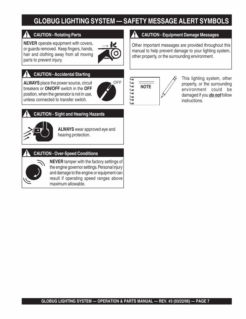
SAFETY MESSAGE ALERT SYMBOLS
The three (3) Safety Messages shown below will inform youabout potential hazards that could injure you or others. TheSafety Messages specifically address the level of exposureto the operator, and are preceded by one of three words:DANGER, WARNING, or CAUTION.
HAZARD SYMBOLS
Potential hazards associated with the GloBug LightingSystem operation will be referenced with Hazard Symbolswhich appear throughout this manual, and will be referencedin conjunction with Safety Message Alert Symbols.
NOTE
GLOBUG LIGHTING SYSTEM — SAFETY MESSAGE ALERT SYMBOLS
Engine exhaust gases containpoisonous carbon monoxide. This gasis colorless and odorless, and cancause death if inhaled. NEVER operatethis equipment in a confined area orenclosed structure that does not provideample free flow air.
Gasoline fuel is extremely flammable,and its vapors can cause an explosion ifignited. DO NOT start the engine nearspilled fuel or combustible fluids.
DO NOT fill the fuel tank while the engine is running orhot. DO NOT overfill tank, since spilled fuel could ignite ifit comes into contact with hot engine parts or sparks fromthe ignition system. Store fuel in approved containers, inwell-ventilated areas and away from sparks and flames.
Engine components can generate extremeheat. To prevent burns, DO NOT touchthese areas while the engine is running orimmediately after operations. Neveroperate the engine with heat shields or heatguards removed.
WARNING - Lethan Exhaust Gasses
You WILL be KILLED or SERIOUSLY injured if you DONOT follow directions.
You CAN be KILLED or SERIOUSLY injured if you DONOT follow directions.
You CAN be INJURED if you DO NOT follow directions.
DANGER
WARNING
CAUTION
WARNING - Explosive Fuel
WARNING - Burn Hazards
ALWAYS wear approved respiratoryprotection when required.
CAUTION - Respiratory Hazard
GLOBUG LIGHTING SYSTEM — OPERATION & PARTS MANUAL — REV. #3 (03/22/06) — PAGE 7
Other important messages are provided throughout thismanual to help prevent damage to your lighting system,other property, or the surrounding environment.
NOTEALWAYS place the power source, circuitbreakers or ON/OFF switch in the OFFposition, when the generator is not in use,unless connected to transfer switch.
NEVER tamper with the factory settings ofthe engine governor settings. Personal injuryand damage to the engine or equipment canresult if operating speed ranges abovemaximum allowable.
ALWAYS wear approved eye andhearing protection.
GLOBUG LIGHTING SYSTEM — SAFETY MESSAGE ALERT SYMBOLS
This lighting system, otherproperty, or the surroundingenvironment could bedamaged if you do not followinstructions.
NEVER operate equipment with covers,or guards removed. Keep fingers, hands,hair and clothing away from all movingparts to prevent injury.
CAUTION - Rotating Parts
CAUTION - Accidental Starting
CAUTION - Sight and Hearing Hazards
CAUTION - Over-Speed Conditions
CAUTION - Equipment Damage Messages

PAGE 8 — GLOBUG LIGHTING SYSTEM — OPERATION & PARTS MANUAL — REV. #3 (03/22/06)
GLOBUG LIGHTING SYSTEM — RULES FOR SAFE OPERATION
■ ALWAYS refuel in a well-ventilated area, away from sparksand open flames.
■ ALWAYS use extreme caution when working withflammable liquids. When refueling, stop theengine and allow it to cool. DO NOT smokearound or near the machine. Fire or explosioncould result from fuel vapors, or if fuel is spilledon a hot engine.
■ The engine of this lighting system/generator requires anadequate free flow of cooling air. NEVER operate thegenerator in any enclosed or narrow area where free flow ofthe air is restricted. Ifthe air flow isrestricted it will causeserious damage tothe generator engineand may cause injuryto people. Rememberthe engine of thelighting system/generator gives offDEADLY carbonmonoxide gas.
WARNING - READ THIS MANUAL
Failure to follow instructions in this manual may lead toSerious Injury or even Death. This equipment is to beoperated by trained and qualified personnel only! Thisequipment is for industrial use only.
The following safety guidelines should always be usedwhen operating the GloBug Lighting System.
The following safety guidelines should always be used whenoperating the GloBug Lighting System:
GENERAL SAFETY
■ DO NOT operate or service thisequipment before reading this entiremanual.
■ This equipment should not be operated by persons under18 years of age.
■ NEVER operate this equipment without proper protectiveclothing, shatterproof glasses, steel-toed boots and otherprotective devices required by the job.
■ NEVER operate this equipment under the influence ofdrugs or alcohol.
■ Whenever necessary, replace nameplate, operation andsafety decals when they become difficult read.
■ Manufacturer does not assume responsibility for anyaccident due to equipment modifications.
■ NEVER use accessories or attachments, which are notrecommended by Multiquip for this equipment. Damageto the equipment and/or injury to user may result.
■ NEVER operate this equipment when not feelingwell due to fatigue, illness or taking medicine.
■ NEVER touch the hot exhaust manifold,muffler or cylinder. Allow these parts tocool before servicing engine or mixer.
■ High Temperatures – Allow the engine to cool beforeadding fuel or performing service and maintenancefunctions. Contact with hot! components can cause seriousburns.
■ NEVER operate the GloBug in an explosiveatmosphere or near combustible materials. Anexplosion or fire could result causing severebodily harm or even death.
■ Topping-off to filler port is dangerous, as it tends to spill fuel.Wipe up any spilled fuel immediately.
AC CIRCUIT
BREAKER
120/240V
30A
120V
30A
20A
20A
0N
OFF
IDLE
CONTROL
OPERA TION
SWITCH
ON
OFF
FULL POWER
SWITCH
120V
120V/240V
OFF
21A
GA
-6H
6000

GLOBUG LIGHTING SYSTEM — OPERATION & PARTS MANUAL — REV. #3 (03/22/06) — PAGE 9
■ ALWAYS make sure that the GloBug is secure on firm levelground so that it cannot slide or shift around, endangeringworkers. Also keep the immediate area free of bystanders.
■ ALWAYS keep area behind GloBug clear of people whileraising and lowering mast.
■ To prevent the GloBug from overturning, NEVER use in windsthat exceed 22 mph(10m/s).
■ To prevent the GloBug from rolling, ALWAYS place theGloBug on a firm flat surface. Surface slant should not exceed5 degrees.
■ To prevent the GloBug from rolling, ALWAYS apply theparking brake. For additional safety place chock blocksbehind the wheels.
■ The GloBug must use a generator that is at least 220lbs. (100 kg) minimum. This will prevent the GloBug fromtipping over.
■ The GloBug should only be used in temperatures between23-104 degrees Fahrenheit (-5 to 40 degrees Celsius).Failure to comply with these operating parameters couldcause the lamp to malfunction and shorten the ballastlife.
■ NEVER use the GloBug in rain, snow or areas of highhumidity that could generate electrical storms.
■ Set the GloBug's tire air pressure to 35.5 psi (245kPa).Check daily. Low tire pressure could adversely affect theparking brake.
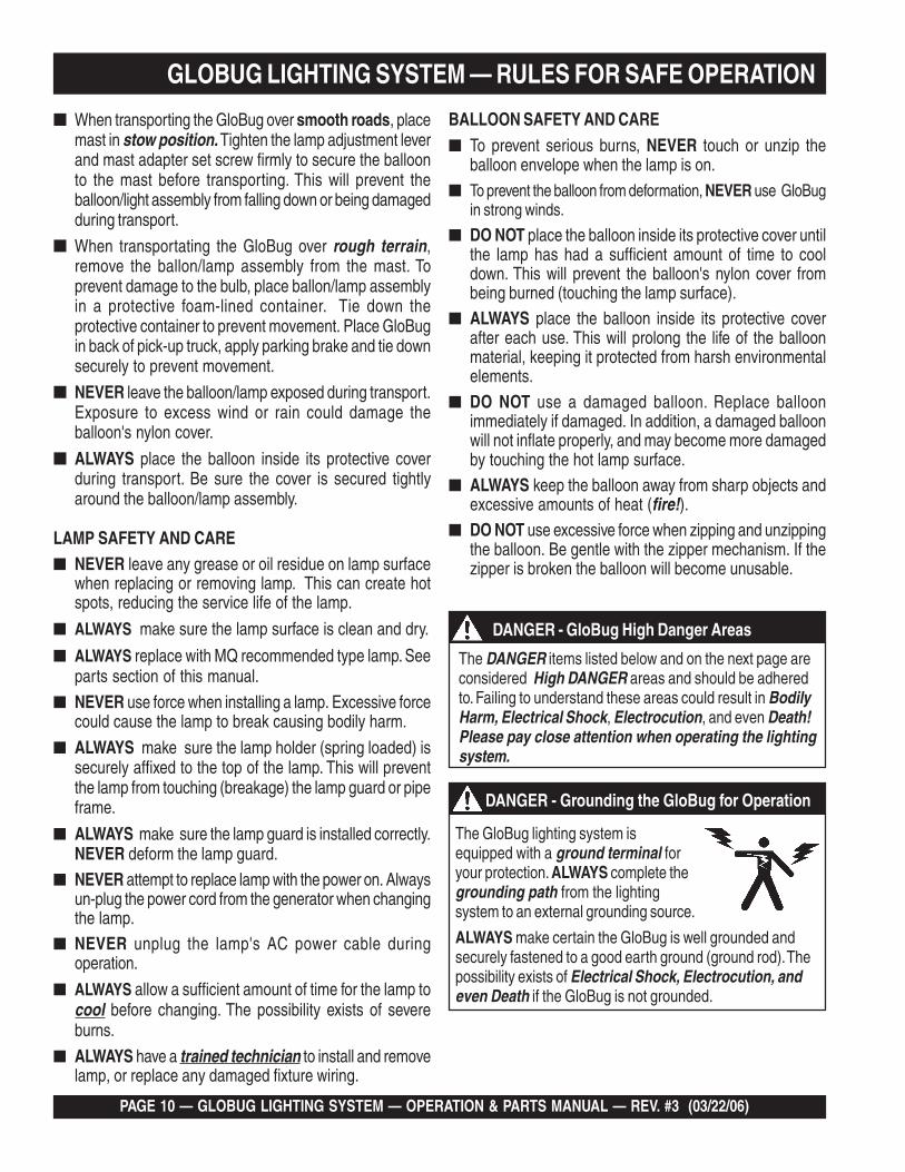
GLOBUG LIGHTING SYSTEM — RULES FOR SAFE OPERATION
LIFTING/TRANSPORTING THE GLOBUG
■ ALWAYS use the lifting hanger, when lifting of the GloBugis required.
PINCHPOINT
■ When raising the mast and to prevent tipping, ALWAYSdeploy outriggers.
■ CHECK the mast and winch cables for wear. If any problemoccurs when lower or raising the mast STOP immediately!Contact a trained MQ technician for assistance.
■ NEVER pivot or retract mast while unit is operating.■ NEVER use the lighting system mast as a crane. DO
NOT lift anything with the mast.■ NEVER attach anything to the lighting system mast.■ ALWAYS lower the tower when not in use, or if high winds
or electrical storms are expected in the area.
■ Use a crane, forklift or suitable lifting device of adequatelifting capability when the lifting of the GloBug is required.
■ Make sure the mast is completely lowered before liftingthe GloBug.
■ When the GloBug is lifted from its correct lifting point, itshould lift straight up (not tilted). DO NOT attempt to liftthe GloBug if its position is tilted while lifting.
INCORRECT
CORRECT
MAST SAFETY■ When raising or lowering the mast,
keep hands and fingers clear ofthe various mast sections, this willprevent hands and fingers fromgetting pinched.
LIFTINGHANGER
LIFTINGHOOK
LIFTINGSCHACKLE
GENERATORLIFTING BALE
PAGE 10 — GLOBUG LIGHTING SYSTEM — OPERATION & PARTS MANUAL — REV. #3 (03/22/06)
GLOBUG LIGHTING SYSTEM — RULES FOR SAFE OPERATION
The DANGER items listed below and on the next page areconsidered High DANGER areas and should be adheredto. Failing to understand these areas could result in BodilyHarm, Electrical Shock, Electrocution, and even Death!Please pay close attention when operating the lightingsystem.
DANGER - GloBug High Danger Areas
■ When transporting the GloBug over smooth roads, placemast in stow position. Tighten the lamp adjustment leverand mast adapter set screw firmly to secure the balloonto the mast before transporting. This will prevent theballoon/light assembly from falling down or being damagedduring transport.
■ When transportating the GloBug over rough terrain,remove the ballon/lamp assembly from the mast. Toprevent damage to the bulb, place ballon/lamp assemblyin a protective foam-lined container. Tie down theprotective container to prevent movement. Place GloBugin back of pick-up truck, apply parking brake and tie downsecurely to prevent movement.
■ NEVER leave the balloon/lamp exposed during transport.Exposure to excess wind or rain could damage theballoon's nylon cover.
■ ALWAYS place the balloon inside its protective coverduring transport. Be sure the cover is secured tightlyaround the balloon/lamp assembly.
BALLOON SAFETY AND CARE■ To prevent serious burns, NEVER touch or unzip the
balloon envelope when the lamp is on.■ To prevent the balloon from deformation, NEVER use GloBug
in strong winds.
■ DO NOT place the balloon inside its protective cover untilthe lamp has had a sufficient amount of time to cooldown. This will prevent the balloon's nylon cover frombeing burned (touching the lamp surface).
■ ALWAYS place the balloon inside its protective coverafter each use. This will prolong the life of the balloonmaterial, keeping it protected from harsh environmentalelements.
■ DO NOT use a damaged balloon. Replace balloonimmediately if damaged. In addition, a damaged balloonwill not inflate properly, and may become more damagedby touching the hot lamp surface.
■ ALWAYS keep the balloon away from sharp objects andexcessive amounts of heat (fire!).
■ DO NOT use excessive force when zipping and unzippingthe balloon. Be gentle with the zipper mechanism. If thezipper is broken the balloon will become unusable.
LAMP SAFETY AND CARE■ NEVER leave any grease or oil residue on lamp surface
when replacing or removing lamp. This can create hotspots, reducing the service life of the lamp.
■ ALWAYS make sure the lamp surface is clean and dry.
■ ALWAYS replace with MQ recommended type lamp. Seeparts section of this manual.
■ NEVER use force when installing a lamp. Excessive forcecould cause the lamp to break causing bodily harm.
■ ALWAYS make sure the lamp holder (spring loaded) issecurely affixed to the top of the lamp. This will preventthe lamp from touching (breakage) the lamp guard or pipeframe.
■ ALWAYS make sure the lamp guard is installed correctly.NEVER deform the lamp guard.
■ NEVER attempt to replace lamp with the power on. Alwaysun-plug the power cord from the generator when changingthe lamp.
■ NEVER unplug the lamp's AC power cable duringoperation.
■ ALWAYS allow a sufficient amount of time for the lamp tocool before changing. The possibility exists of severeburns.
■ ALWAYS have a trained technician to install and removelamp, or replace any damaged fixture wiring.
The GloBug lighting system isequipped with a ground terminal foryour protection. ALWAYS complete thegrounding path from the lightingsystem to an external grounding source.
ALWAYS make certain the GloBug is well grounded andsecurely fastened to a good earth ground (ground rod). Thepossibility exists of Electrical Shock, Electrocution, andeven Death if the GloBug is not grounded.
DANGER - Grounding the GloBug for Operation

GLOBUG LIGHTING SYSTEM — OPERATION & PARTS MANUAL — REV. #3 (03/22/06) — PAGE 11
GLOBUG LIGHTING SYSTEM — RULES FOR SAFE OPERATION
Emergencies
■ ALWAYS know the location of thenearest fire extinguisher.
ALWAYS keep electrical cords in good condition. Worn,bare or frayed wiring can cause electricalshock, thus causing Bodily Harm oreven Death.
NEVER grab or touch a live powercord with wet hands, the possibilityexists of Electrical Shock,Electrocution, and even Death!
POWERCORD
(POWER ON)
WETHANDS
DANGER - GloBug Electric Shock Hazards
ALWAYS make sure thearea above GloBug isopen and clear ofoverhead power linesand other obstructions.The tower extends inexcess of 16.5 ft. (5meters). Contact withoverhead powerlines orother obstructions couldresult in equipmentdamage, Serious Injury or Death!
DANGER - GloBug Overhead Obstructions
ACCIR
CUIT
BREAKER
ACCIR
CUIT
BREAKER
120/240V
120/240V
30A30A
120V
30A
20A
20A
0N
OFF
IDLE
CONTROL
OPERATION
SWITCH
ON
OFF
FULL POWER
SWITCH
120V
120V/240V
120
V
OFF
OFF
21A21A
GA
-6H
6000
Maintenance Safety
■ NEVER lubricate components or attempt service on a runningGloBug.
■ ALWAYS allow the GloBug a proper amount of time to coolbefore servicing.
■ Keep the GloBug in proper running condition.
■ Fix damage to the GloBug immediately and always replacebroken parts.
■ ALWAYS use the required tool for the job application.Using damaged or worn tools or using tools inappropriatefor the required application is very dangerous, and maycause damage tothe machine andservice personnel.Make sure to usethe appropriate toolfor the specific job.
■ In emergencies always know the location of the nearest phoneor keep a phone on the job site. Also know the phonenumbers of the nearest ambulance, doctor and firedepartment. This information will be invaluable in the caseof an emergency.
■ ALWAYS know the location of the nearestfirst aid kit.
DANGER - GloBug Electric Shock Hazards
NEVER operate theGloBug or handle anyelectrical equipmentwhile standing in water,while bare foot, whilehands are wet, or in therain. A dangerouselectrical shock couldoccur causing SevereBodily Harm or evenDeath.
ACCIR
CUIT
BREAKER
ACCIR
CUIT
BREAKER
120/240V
120/240V
30A30A
120V
30A
20A
20A
0N
OFF
IDLE
CONTROL
OPERATION
SWITCH
ON
OFF
FULL POWER
SWITCH
120V
120V/240V
120
V
OFF
OFF
21A21A
GA
-6H
6000

PAGE 12 — GLOBUG LIGHTING SYSTEM — OPERATION & PARTS MANUAL — REV. #3 (03/22/06)
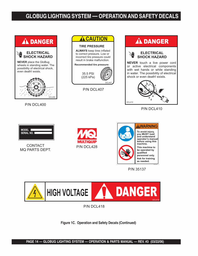
Machine Safety Decals
The GloBug is equipped with a number of safety decals, Figures 1A through 1C. These decals are provided for operator safety andmaintenance information. The illustrations below and on the next page show these decals as they appear on the machine. Shouldany of these decals become unreadable, replacements can be obtained from your dealer.
GLOBUG LIGHTING SYSTEM — OPERATION AND SAFETY DECALS
Figure 1A. Operation and Safety Decals

GLOBUG LIGHTING SYSTEM — OPERATION & PARTS MANUAL — REV. #3 (03/22/06) — PAGE 13
GLOBUG LIGHTING SYSTEM — OPERATION AND SAFETY DECALS
Figure 1B. Operation and Safety Decals (Continued)
PAGE 14 — GLOBUG LIGHTING SYSTEM — OPERATION & PARTS MANUAL — REV. #3 (03/22/06)
GLOBUG LIGHTING SYSTEM — OPERATION AND SAFETY DECALS
Figure 1C. Operation and Safety Decals (Continued)

GLOBUG LIGHTING SYSTEM — OPERATION & PARTS MANUAL — REV. #3 (03/22/06) — PAGE 15
GLOBUG LIGHTING SYSTEM — SPECIFICATIONS
snoitacificepS.1elbaTguBolG
ledoM CB411BG
egatloVtupnI CAV021
ycneuqerF esahP-elgniSzH06
tnerruC.xaM spmA5.9
rotareneGhtiwytilibatSdniW )hpk64.08(hpm56
)rotarenegssel(thgieW )gk011(.sbl342
pmaL
epyTpmaL edadilaHlateMttaW0001)1(
snemuL 000,211
)°063(egarevoCthgiL )sretem27.54(.tf051
)lanidutignoL(erutarepmeTecafruS .xaM)C°742(F°6.674
)lasrevsnarT(erutarepmeTecafruS .xaM)C°412(F°2.714
rotoMnaF
rotoMnaFnoollaB zH06,CAV511
tnerruC.xaM spmA063.
erusserP )APk6.512(ISP62.13
noollaB
retemaiD )sretem1.1(.TF9.3
lairetaM nolyNtnatsiseRtaeH
erutarepmeTgnitsiseRtaeH )C°081~061(F°653~023
erutarepmeTgnitleM )C°062(F°005
noollaBfoerutarepmeTlanretnI egarevA)C°25(F°621
ecnatsiseRretaW Hmm005,1 20
tsaM
segatSforebmuN 4
thgieHmumixaM )sretem5(.TF5.61
snoisnemiD 2elbaT,2erugiFeeS
rotareneG launaMrotareneGdeificepSeeS

PAGE 16 — GLOBUG LIGHTING SYSTEM — OPERATION & PARTS MANUAL — REV. #3 (03/22/06)
GLOBUG LIGHTING SYSTEM — DIMENSIONS
Figure 2. Dimensions
SNOISNEMID.2ELBAT
ecnerefeRretteL
noitpircseD ).mm(.tfnoisnemiDecnerefeR
retteLnoitpircseD ).mm(.tfnoisnemiD
A esaBleehW ).mm118(.tf66.2 F )noitisoPdeyolpeDtsaM(thgieH.xaM ).mm400,5(.tf14.61
B )noitisoPdewotStsaM(thgieH ).mm676,1(.tf5.5 G )leehWraeRottnorF(htgneL ).mm140,1(.tf14.3
C thgieHeldnaH ).mm988(.tf19.2 H )reggirtuOotleehWtnorF(htgneL ).mm374,1(.tf38.4
D htgneLgaBnoollaB ).mm686(.tf52.2 I retemaiDnoollaB ).mm341,1(.tf57.3
E mroftalPotkooHtfiL ).mm955(.tf38.1 J )deyolpeDsreggirtuO(htdiW ).mm844,1(.tf57.4
GLOBUG LIGHTING SYSTEM — OPERATION & PARTS MANUAL — REV. #3 (03/22/06) — PAGE 17
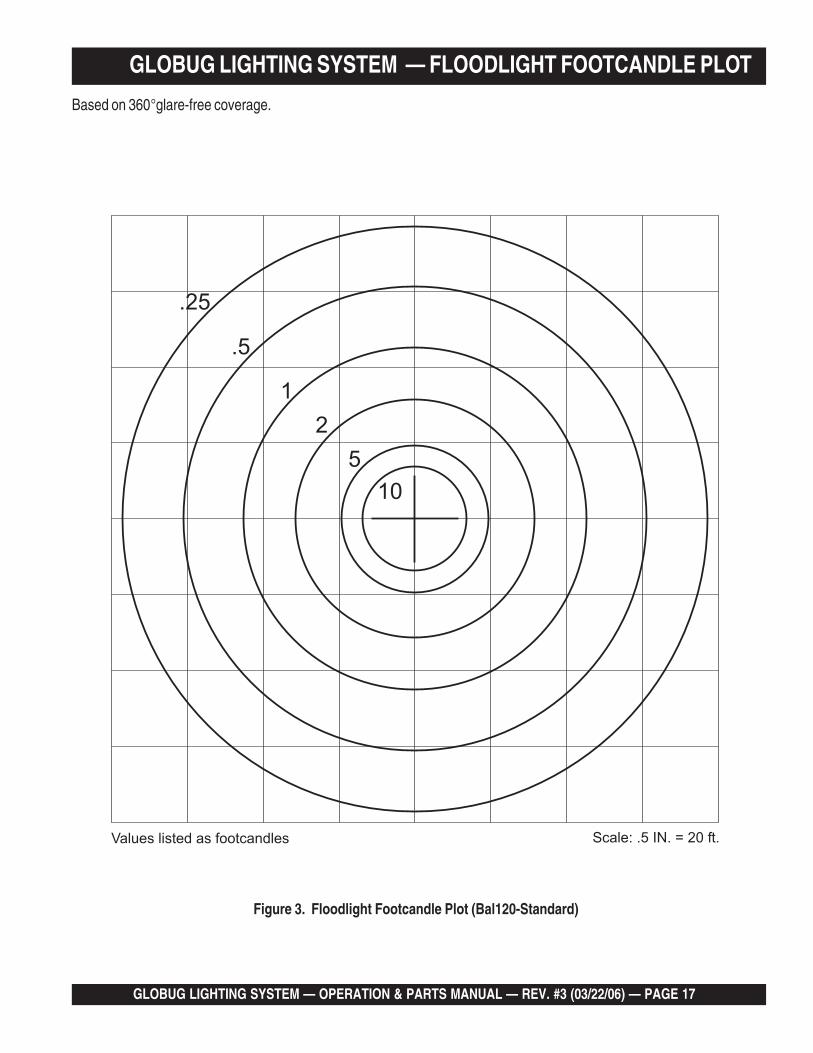
GLOBUG LIGHTING SYSTEM — FLOODLIGHT FOOTCANDLE PLOT
Figure 3. Floodlight Footcandle Plot (Bal120-Standard)
Based on 360°glare-free coverage.

PAGE 18 — GLOBUG LIGHTING SYSTEM — OPERATION & PARTS MANUAL — REV. #3 (03/22/06)
GLOBUG LIGHTING SYSTEM — FLOODLIGHT FOOTCANDLE PLOT
Figure 4. Floodlight Footcandle Plot (BAL120R-Reflector)
Based on 360°glare-free coverage.

GLOBUG LIGHTING SYSTEM — OPERATION & PARTS MANUAL — REV. #3 (03/22/06) — PAGE 19
GLOBUG LIGHTING SYSTEM — FLOODLIGHT FOOTCANDLE PLOT
Figure 5. Floodlight Footcandle Plot (BAL-115D-Drum Shaped)
360 degree coverage

PAGE 20 — GLOBUG LIGHTING SYSTEM — OPERATION & PARTS MANUAL — REV. #3 (03/22/06)
GLOBUG LIGHTING SYSTEM — GENERAL INFORMATIONThe Multiquip GloBug Lighting System is a general purposefloodlight tower intended for emergency and remote lightingconditions. The GloBug can be powered by a variety ofMultiquip's series generators. Power requirements for runningthe GloBug are 120 VAC, 60 Hz @ 9.5 amps. The GloBugcan be powered by any MQ portable generator with an outputof 2.9 kW or greater.
The lighting system of Multiquip's GloBug Lighting Systemis comprised of one "Metal Halide" 1000 watt lamp. Thislamp has an output of 112,000 lumens. Typical lightingcoverage is in excess 150 ft. (45.72 meters) in a 360 degreepattern.
Located underneath the generator support platform is aweather resistant ballast box that contains the ballast forstarting the floodlight. The floodlight is activated by anON/OFF switch located at the base of the mast.
For ease of service or transport, the floodlight is equippedwith a quick-disconnect connector that allows the lamp fixtureto be removed quickly. This feature is extremely useful duringtransport of the lighting system over rough terrain. It is alwaysbest to remove the floodlight and pack it safely so it will notbe damaged.
ALWAYS make sure thearea above GloBug isopen and clear ofoverhead power linesand other obstructions.The tower extends inexcess of 16.5 ft. (5meters). Contact withoverhead powerlines orother obstructions couldresult in equipmentdamage, Serious Injury or Death!
DANGER - GloBug Overhead Obstructions
ACCIR
CUIT
BREAKER
ACCIR
CUIT
BREAKER
120/240V
120/240V
30A30A
120V
30A
20A
20A
0N
OFF
IDLE
CONTROL
OPERATION
SWITCH
ON
OFF
FULL POWER
SWITCH
120V
120V/240V
120
V
OFF
OFF
21A21A
GA
-6H
6000
The lighting system can be raised vertically in excess of 31.5 feet(9.6 meters) by means of a manual winch. The tower tensioningsystem is designed to provide the necessary tension to safelycontrol the pivot of the tower. Outriggers must always be deployedprior to raising the mast.
NOTE
All information related to thegenerator will be referenced in aseparate (supplied) "Operationand Parts Manual". Operationand maintenance of the generatorwill not be referenced in thismanual.
Alarm BuzzerThe GloBug is equipped with a "Balloon Alarm" feature. Thisalarm will sound if the lamp is on and the balloon attempts tomake contact with the hot! surface of the lamp . This alarmis intended to inform the operator that a potential burn hazardexits between the lamp surface and the balloon material.
Always allow the lamp to cool down before removing the ACpower from the GloBug. In the event the balloon begins todeflate during normal operation, immediately place theGloBug's ON/OFF switch in the OFF position.
Please read carefully the specifiedgenerator manual that will accompany yourGloBug lighting system. This manual willexplain how to operate and maintain thegenerator.
Balloon EnvelopesThe GloBug can be configured with a variety of balloonenvelopes (canopy). Please contact the MQ sales departmentfor the balloon of your choice. The GloBug, Model GB114BCcomes with the standard balloon (BAL-120).

GLOBUG LIGHTING SYSTEM — OPERATION & PARTS MANUAL — REV. #3 (03/22/06) — PAGE 21
NOTE PAGE
PAGE 22 — GLOBUG LIGHTING SYSTEM — OPERATION & PARTS MANUAL — REV. #3 (03/22/06)
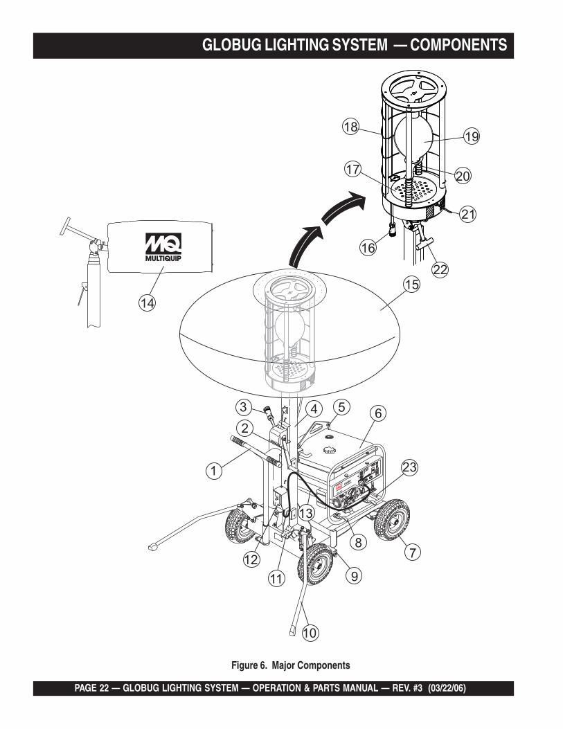
GLOBUG LIGHTING SYSTEM — COMPONENTS
Figure 6. Major Components
GLOBUG LIGHTING SYSTEM — OPERATION & PARTS MANUAL — REV. #3 (03/22/06) — PAGE 23
GLOBUG LIGHTING SYSTEM — COMPONENTSFigure 6 shows the location of the controls and componentsfor the GloBug Lighting System. The functions of each controlis described below:
1. Steering Handle – The GloBug can be moved in eithera forward or reverse direction by pulling back or pushingforward on the T-handle. In addition the front wheels aredesigned to turn in the opposite direction of the T-handleplacement thus allowing the GloBug to turn either left orright.
2. Mast Winch – Use this mechanical winch to raise andlower the mast. Always be on the lookout for overheadobstructions. Keep immediate area free of bystandersand debris when raising the mast.
3. Lamp Power Cable (Generator) – Connect this quick-disconnect cable plug (generator-side) to the lamp powercable plug.
4. Mast – This mast is comprised of four separate stages.The mast can be raised in excess of 16.5 ft. (5 meters).Again when raising the mast, always be on the lookout foroverhead obstructions.
5. Lift Hanger – When lifting of the GloBug is requiredalways use a suitable lifting device of adequate liftingcapability. NEVER stand underneath the GloBug while itis being lifted.
6. Generator – MQ GA-Series type generator. This genera-tor will supply the necessary power to run the GloBug. Foroperation of generator read generator Operation Manualsupplied with GloBug.
7. Tires – The GloBug uses 4 pneumatic type tires.Replace with only recommended type tire . NEVER allowthe rear tires to go flat. This could adversely affect thebraking system. Inflate tires to 35.5 psi (245kPa).
8. Locking Clamps – To secure the generator to theGloBug cart platform, place clamps (4) around the pipeframe of the generator. Tighten securely to preventmovement.
9. Brake Pad – When the brake pedal is pressed, this padwill strike and hold the rear tires in place. Make sure reartires are inflated to the correct air pressure.
10. Outriggers – ALWAYS deploy the outriggers whenraising the mast.
11. Brake Pedal – Step on this pedal to apply the brakes. Torelease the brakes, press down on brake pedal again.
12. ON/OFF Switch – Place this switch in the ON positionto turn on the lamp. To turn off the lamp place in the downposition (OFF). Please wait for approximately 10 minutesbefore attempting to turn the lamp back on.
13. Power Cable – Connect this cable to a 120 VAC, 60 Hzpower source.
14. Balloon Storage Bag – Store the balloon in this storagebag when the GloBug is not in use. Allow a sufficientamount of time for the lamp to cool down before placingballoon inside storage bag. Possibility exists of balloongetting burned.
15. Balloon – This balloon is made of heat resistant nylon,with a diameter of 3.9 ft. (1,150 mm). The balloon shall beinflated to a pressure of 31.26 psi (215.6 kPA).
16. Lamp Power Cable (Balloon) – Connect this quick-disconnect cable plug (balloon-side) to the generatorpower cable plug.
17. Fan Motor (Blower) – This electric motor is responsiblefor inflating the balloon. It will supply a pressure of 31.26psi (215.6 kPA). Please note that the balloon will begin toinflate as soon as power is applied to the GloBug. TheOFF/ON switch does not control the electric fan motor.
18. Lamp Guard – This guard (cage) protects the lamp frombeing hit by objects.
19. Lamp – 1000 watt metal-halide type lamp. Replace withonly MQ recommended type lamp. Always allow asufficient amount of time for the lamp to cool downbefore changing.
20. Lamp Holder – Screw lamp into this holder. If lampbecomes difficult to screw into holder or holder isdamaged, replace holder.
21. Balloon Alarm Buzzer – Will sound during normaloperation if the balloon attempts to make contact with thelamp's hot! surface. If this condition occurs, immediatelyplace the GloBug's ON/OFF switch in the OFF position.
22. Adjust Lever – This lever allows the lamp to be posi-tioned up or down. Turn counterclockwise to release lampand position. Turn clockwise to tighten.
23. Ballast Compartment – Provides the necessary elec-tronics to light the lamp. To gain access to the ballastcompartment the generator must be removed from thecart platform.

PAGE 24 — GLOBUG LIGHTING SYSTEM — OPERATION & PARTS MANUAL — REV. #3 (03/22/06)
GLOBUG LIGHTING SYSTEM — PRE-SETUP
CAUTION - Read Manual
Please read this entire manual carefullybefore attempting to operate the GloBug.Failure to read this manual could causedamage to the GloBug and serious injuryto the operator.
GloBug Setup
1. Using the T-handle (Figure 7) place the GloBug on afirm level surface so that it will not slide or turn over.
3. Lift up on each outrigger (2) from its stow position, rotatebackwards and place it in the deployed position, as shownin Figure 9. The outriggers will automatically lock in placeonce they touch the ground,
Figure 7. T-Handle (Directional Control)
2. To apply the parking brake (Figure 8), step on the brakepedal and pull back on the T-handle. This will lock therear wheels. For additional safety use chock blocks toprevent rolling.
PARKINGBRAKE SET
STEP DOWNON BRAKE PEDAL
Figure 8. Parking Brake (Set Position)
ACCIR
CUIT
BREAKER
ACCIR
CUIT
BREAKER
120/240V
120/240V
30A30A
120V
30A
20A
20A
0N
OFF
IDLE
CONTROL
OPERATION
SWIT
CH
ON
OFF
FULL
PO
WE
R
SW
ITC
H
120V
120V/240V
120
V
OFF
OFF
21A21A
GA
-6H
6000
OU
TRIG
GER
S
DEPLO
YED
STOW
POSITION
Figure 9. Outriggers (Deployed Position)
4. Expose the balloon by pulling down on the velcro tabsand unzip the protective cover as shown in Figure 10.Next, fold the protective cover into itself and zip.
Figure 10. Exposing the Balloon.
GLOBUG LIGHTING SYSTEM — OPERATION & PARTS MANUAL — REV. #3 (03/22/06) — PAGE 25
GLOBUG LIGHTING SYSTEM — PRE-SETUP
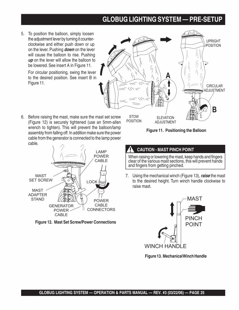
5. To position the balloon, simply loosenthe adjustment lever by turning it counter-clockwise and either push down or upon the lever. Pushing down on the leverwill cause the balloon to rise. Pushingup on the lever will allow the balloon tobe lowered. See insert A in Figure 11.
For circular positioning, swing the leverto the desired position. See insert B inFigure 11.
Figure 11. Positioning the Balloon
6. Before raising the mast, make sure the mast set screw(Figure 12) is securely tightened (use an 5mm-allenwrench to tighten). This will prevent the balloon/lampassembly from falling off. In addition make sure the powercable from the generator is connected to the lamp powercable.
Figure 12. Mast Set Screw/Power Connections
7. Using the mechanical winch (Figure 13), raise the mastto the desired height. Turn winch handle clockwise toraise mast.
Figure 13. Mechanical Winch Handle
CAUTION - MAST PINCH POINT
When raising or lowering the mast, keep hands and fingersclear of the various mast sections, this will prevent handsand fingers from getting pinched.

PAGE 26 — GLOBUG LIGHTING SYSTEM — OPERATION & PARTS MANUAL — REV. #3 (03/22/06)
DANGER - HIGH VOLTAGE POWER LINES
When raising mast, ALWAYS be onthe lookout for overhead obstructionssuch as high voltage power lines. Thepossibility exists of electrocution,even death! if the GloBug comes incontact with high voltage power lines.
GLOBUG LIGHTING SYSTEM — PRE-SETUP/OPERATION
Applying Power1. Make sure the power ON/OFF switch (Figure 14) located
near the bottom of the mast is in the OFF position.
2. The GloBug has a power requirement of 120 VAC, 60 Hz@ 9.5 amps. Connect the GloBug's AC power cord tothe 120 VAC twist-lock receptacle (Figure 15) on the thesupplied generator.
Figure 14. Power OFF/ON Switch (OFF Position)
Figure 15. 120 VAC Receptacle
CAUTION - READ GENERATOR MANUAL
Before attempting to operate thegenerator, READ the entire operationsection of the manual. Failure to readmanual could cause severe damage tothe equipment and bodily harm to theoperator.
4. Notice that the balloon envelope will begin to deploy assoon as power is applied by an active generator. Thisfunction is not controlled by the power ON/OFF switch.
5. Wait until the balloon is fully deployed before attemptingto turn on the lamp. The possibility exists of the balloongetting burned (touching the lamp).
6. If the balloon is fully deployed, place the GloBug's ON/OFF switch in the ON position.
Figure 16. Power OFF/ON Switch (ON Position)
7. The lamp should now be on. If the lamp is not on, checkall connections and repeat steps 1 through 6. If the lampstill does not come on contact the MQ servicedepartment.
Shutdown1. Place the power ON/OFF switch (Figure 17) in the OFF
position.
Figure 17. Power OFF/ON Switch (OFF Position)
CAUTION - LAMP COOL DOWN
Allow a sufficient amount of time (15-20 minutes) for thelamp (Figure 18) to cool down before turning offgenerator. The possibility exists of the balloon gettingburned (touching the lamp).
2. Disconnect the GloBug's AC power cable from thegenerator. The balloon should begin to deflate.
3. Shutdown generator as referenced in the "ShutdownSection" of the supplied generator manual.3. Start the generator as referenced in the "Start-up
Section" of the supplied generator manual.

GLOBUG LIGHTING SYSTEM — OPERATION & PARTS MANUAL — REV. #3 (03/22/06) — PAGE 27
GLOBUG LIGHTING SYSTEM — SHUTDOWN
Figure 18. Hot Lamp Surface
4. Using the mechanical winch (Figure 6, item 2), fullylower the mast. Turn winch handle counter-clockwise tolower mast.
5. Using the adjustment lever (Figure 6, item 22) place theballoon/lamp assembly in the stow position.
6. Unzip the protective cover as shown in Figure 19, andplace cover over balloon/lamp assembly.
7. To unlock outriggers, push downward on the counter-weight lever indicated by arrow (Figure 20). Grab hold ofoutrigger, pull upward, push down and place in stowposition (Figure 21)..
Figure 20. Outriggers (Released)
Figure 19. Covering the Lamp/Balloon Assembly Figure 22. Parking Brake (Release Position)
8. Press down on the top of the brake pedal (Figure 22)and hold, then release. This action will dis-engage thebrake mechanism and allow the GloBug to be moved.
Storage1. Wipe and dir t or foreign matter that may have
accumulated on the GloBug during operation. Use a milddetergent to clean the unit. DO NOT spray the enginewith water.
2. Avoid storing the GloBug in areas that can be exposedto rain, harsh elements, and high humidity.
3. Place the GloBug in a clean dry location away from dirtand debris.
Figure 21. Outriggers (Stow Position)

PAGE 28 — GLOBUG LIGHTING SYSTEM — OPERATION & PARTS MANUAL — REV. #3 (03/22/06)
GLOBUG LIGHTING SYSTEM — MAINTENANCE
Removing the Lamp/Balloon Assembly
1. Place the lamp/ballon assembly in the STOW position.
2. With a 5 mm allen wrench, loosen the set screw (Figure 23) thatsecures the lamp to the mast adapter stand.
3. Disconnect the lamp power cable as shown in Figure 23,and slide the balloon/lamp forward from the mast adapterstand. Place lamp/balloon assembly on a suitable workbench that is free of dirt, and sharp objects that coulddamage the balloon.
Removing the Lamp
1. Expose the balloon (Figure 24) by pulling down on thevelcro tabs and unzip the protective cover as shown inFigure 19. Next, fold the protective cover into itself andzip.
Figure 23. Removing the Balloon/Lamp
Figure 24. Exposing the Balloon
Figure 25. Removing the Lamp Guard
3. Push down and hold the lamp holder (spring loaded) awayfrom the lamp (Figure 26). Unscrew the lamp (turn counter-clockwise) from the lamp socket.
Figure 26. Removing the Lamp
CAUTION - READ SAFETY GUIDELINES
Before performing any maintenanceprocedures, be sure to READ the lamp,balloon, and general safety guidelines inthis manual. Failure to read andunderstand these safety guidelinescould cause severe equipment damageand bodily harm.
CAUTION - BALLOON ZIPPER SAFETY
DO NOT use excessive force when zipping orunzipping the balloon. The possibility existsof the zipper tearing, which would make theballoon unusable.
2. Unzip the zipper (Figure 24) at the bottom of the balloonand roll the balloon envelope upwards to expose the lamp(Figure 25). Remove the lamp guard to gain access to thelamp.. DO NOT use excessive force when un-zippingthe balloon.
GLOBUG LIGHTING SYSTEM — OPERATION & PARTS MANUAL — REV. #3 (03/22/06) — PAGE 29
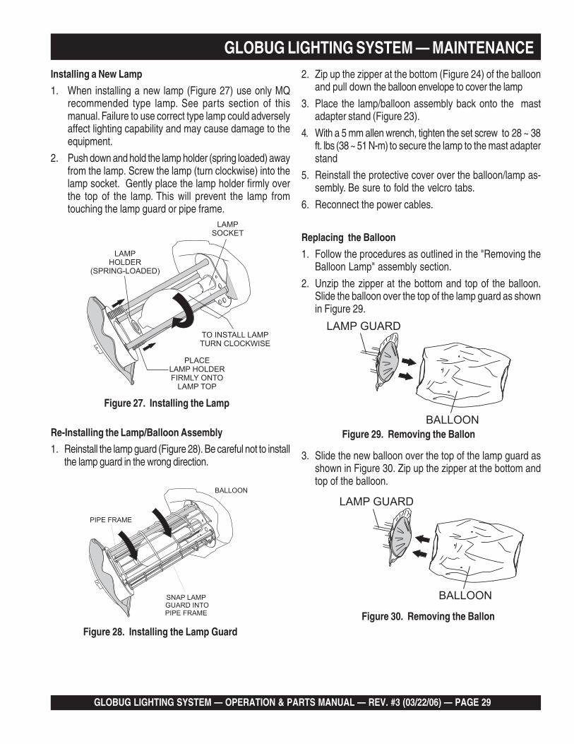
Installing a New Lamp
1. When installing a new lamp (Figure 27) use only MQrecommended type lamp. See parts section of thismanual. Failure to use correct type lamp could adverselyaffect lighting capability and may cause damage to theequipment.
2. Push down and hold the lamp holder (spring loaded) awayfrom the lamp. Screw the lamp (turn clockwise) into thelamp socket. Gently place the lamp holder firmly overthe top of the lamp. This will prevent the lamp fromtouching the lamp guard or pipe frame.
Figure 27. Installing the Lamp
GLOBUG LIGHTING SYSTEM — MAINTENANCE
Re-Installing the Lamp/Balloon Assembly
1. Reinstall the lamp guard (Figure 28). Be careful not to installthe lamp guard in the wrong direction.
2. Zip up the zipper at the bottom (Figure 24) of the balloonand pull down the balloon envelope to cover the lamp
3. Place the lamp/balloon assembly back onto the mastadapter stand (Figure 23).
4. With a 5 mm allen wrench, tighten the set screw to 28 ~ 38ft. lbs (38 ~ 51 N-m) to secure the lamp to the mast adapterstand
5. Reinstall the protective cover over the balloon/lamp as-sembly. Be sure to fold the velcro tabs.
6. Reconnect the power cables.
Figure 28. Installing the Lamp Guard
3. Slide the new balloon over the top of the lamp guard asshown in Figure 30. Zip up the zipper at the bottom andtop of the balloon.
Figure 29. Removing the Ballon
Replacing the Balloon
1. Follow the procedures as outlined in the "Removing theBalloon Lamp" assembly section.
2. Unzip the zipper at the bottom and top of the balloon.Slide the balloon over the top of the lamp guard as shownin Figure 29.
Figure 30. Removing the Ballon

PAGE 30 — GLOBUG LIGHTING SYSTEM — OPERATION & PARTS MANUAL — REV. #3 (03/22/06)
GLOBUG LIGHTING SYSTEM — MAINTENANCE
Check Cable Wear
The wire rope (cable) that raises and extends the mast is a veryimportant part of the GloBug lighting system. Following the pro-cedure below when replacing wire rope (cable).
Wire rope (cable) will fail if it is worn, frayed, misused, crushed,kinked or damaged in any way. ALWAYS check the cable andpulley for any abnormalities before use.
DO NOT use it if there is even the slightest cause forconcern and replace any damaged cable or pulley immediately.
DANGER - Lighting System Cable SystemSafety
Figure 31. Winch/Cable Removal
Removing the Hanger
1. Remove the M12 x 40 bolt (Figure 32) from the hangersupport assembly, then remove the hanger. Set hangeraside in a safe place where it will not get damaged.
Figure 32. Removing the Hanger
Removing the Lamp Cable1. Cut all the cable zip ties (Figure 33) that secure the lamp
cable to the various mast sections.
2. Remove the lamp cable from the various mast sectionsand set cable aside in a safe place where it will not getdamaged. Mark the order of the cable sections so thatthey can be placed back in the same order. Make surecable is laid flat and out of the way so that personnel willnot trip over it.
Removing the Lamp/Balloon Assembly1. Place the lamp/ballon assembly in the STOW position.
2. With a 5 mm allen wrench, loosen the set screw (Figure 23) thatsecures the lamp to the mast adapter stand.
3. Remove the lamp/balloon assembly from the mast adapterstand and set aside in a safe place where it will not getdamaged.
Removal of Winch1. Fully lower the mast to its vertical resting position.
2. Remove the four retaining screws and washers (Figure 31)that secure the winch cover. Remove the winch cover.
3. Loosen the winch cable retaining screw. Pull and removethe winch cable from the locking pin.
4. Remove the three retaining screws and washers that securethe winch to the mast. Remove the winch.
Figure 33. Cutting the Lamp Cable Zip Ties

GLOBUG LIGHTING SYSTEM — OPERATION & PARTS MANUAL — REV. #3 (03/22/06) — PAGE 31
Pulling-Out the Mast Sections
1. Grab hold of the main mast (Figure 34) and begin pullingthe mast sections upwards. Start with second mast, thenthe third mast and finally the fourth.
2. From the main mast, pull the winch cable wire to releasethe safety stopper pulley at the second mast.
Figure 34. Mast Sections
GLOBUG LIGHTING SYSTEM — MAINTENANCE
NOTE
If the winch cable wire cannotbe pulled because of breakageof the wire itself, the safetystoppers installed in the sec-ond mast will lock automaticallyat the places indicated by thearrows in Figure 35.
3. Disconnect the winch cable wire from the fourth mast bypulling it out.
4. Each mast section should be equally spaced about 12-inches from the preceding mast section. See Figure 34.
Figure 35. Cable Release Access Point
5. To release the safety stopper without pulling the cablewire when removing the second mast from the first (mainmast), insert a screwdriver (Figure 36) nearest the holewhere the latch is caught. Press down on the screwdriverto lift the pulley inside the second mast upward. Re-move the screwdriver lifting the second mast upwardsas the latch is being pulled back. The second mast shouldnow be able to be pulled out from the first mast.
Figure 36. Releasing the Safety Stop Latches
WARNING - Mast Service SafetyThe mast sections are heavy and awkward to handle. Useproper lifting devices and procedures when servicing the mastand its components.
PAGE 32 — GLOBUG LIGHTING SYSTEM — OPERATION & PARTS MANUAL — REV. #3 (03/22/06)
Installation of Winch Cable1. Route (pass) a new winch cable through the main mast
pulley � (Figure 37).
2. Route the winch cable around the upper pulley ����� ofthe third mast section from back to front.
3. Next, route the winch cable around the lower pulley �����of the third mast section from back to front.
4. Route the winch cable around the upper pulley ����� of thesecond mast section from back to front.
CAUTION - Winch Cable Safety Stopper
When placing the second mast into the main mast (first), pinch(squeeze) the pulley and pin with pliers (Figure 38) to hold thestopper (cable latch). This will keep the cable stop latch frombeing activated.
10.Route the tip of the winch cable (Figure 39) through theeyelet retaining stud. Insert cable retaining screw at topof stud and tighten.
Figure 38. Bypassing Cable Stop Latch
Figure 39. Connecting the Winch Cable to the Winch
5. Route the winch cable through the lower bracket of thethird mast section
6. Route the winch cable around the lower pulley ����� of thesecond mast from front to back.
7. Continue pulling the cable and slide down the mast, be-ing careful not to activate the cable stop latches.
8. Route the cable around the pulley of the first mast � .
9. Place the second mast into the main (first) mast. Next,place the third mast into the second, and finally placethe fourth mast into the third.
Figure 37. Attaching the Winch Cable
GLOBUG LIGHTING SYSTEM — MAINTENANCE

GLOBUG LIGHTING SYSTEM — OPERATION & PARTS MANUAL — REV. #3 (03/22/06) — PAGE 33
Ballast Box Removal
Dangerous conditions exists inside the ballastcompartment. Please use extreme caution whenperforming maintenance on the ballast box.NEVER touch the ballast or ballast cover whilethe lamp is on. These components generate anextreme amount of heat, which makes their surfaces very hot!.ALWAYS allow the ballast box and cover surface to cool downbefore servicing.
WARNING - HOT SURFACE (BALLAST)
The electronic components of the ballastgenerate high voltage conditions. Theseconditions can be lethal and cause bodilyharm, even death. When performingmaintenance or troubleshooting, have onlyexperienced personnel work on the ballast.
DANGER - HIGH VOLTAGE (BALLAST)
The ballast electronics are located within the cart frame of theGloBug. To gain access to the ballast (Figure 40), remove the 6retaining screws (M8 X 25) that secure the ballast cover to thecart.
Figure 40. Removing the Ballast
Installation of Winch1. Reinstall the three retaining screws (Figure 31) and washers
that secure the winch to the mast. Tighten screws between24~ 33 ft-lbs. (33 ~ 45 N-m).
2. Install the four retaining screws and washers (Figure 31) thatsecure the winch cover. Tighten securely.
3. Turning the winch handle clockwise, wind the cable tightlyaround the winch shaft.
4. Raise, extend, retract and lower the mast several times toverify correct operation.
5. If the winch malfunctions, such as defective brake mecha-nism, replace entire winch assembly immediately.
Installing the Hanger
1. Reinstall the M12 x 40 bolt (Figure 32) that supports thehanger onto the main mast. Tighten bolt between 28~ 38ft-lbs. (38 ~ 51 N-m).
Installing the Lamp Power Cable
1. Check the entire lamp cable for any signs of wear, suchas cuts or frays. If the cable is damaged in any way,replace entire cable. DO NOT use a worn or damagedcable to operate the GloBug. The possibility exists ofshock or electrocution.
2. Using zip ties connect the lamp power cable to the vari-ous mast sections as shown in Figure 33. Remember toconnect the lamp cables to the mast in the same orderthat they were removed.
3. Cutoff any excess zip tie material.
GLOBUG LIGHTING SYSTEM — MAINTENANCE
PAGE 34 — GLOBUG LIGHTING SYSTEM — OPERATION & PARTS MANUAL — REV. #3 (03/22/06)
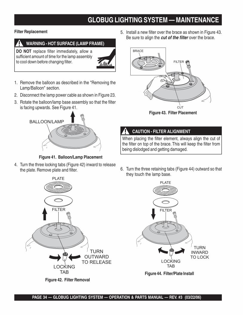
Filter Replacement
GLOBUG LIGHTING SYSTEM — MAINTENANCE
1. Remove the balloon as described in the "Removing theLamp/Balloon" section.
2. Disconnect the lamp power cable as shown in Figure 23.
3. Rotate the balloon/lamp base assembly so that the filteris facing upwards. See Figure 41.
DO NOT replace filter immediately, allow asufficient amount of time for the lamp assemblyto cool down before changing filter.
WARNING - HOT SURFACE (LAMP FRAME)
Figure 41. Balloon/Lamp Placement
4. Turn the three locking tabs (Figure 42) inward to releasethe plate. Remove plate and filter.
Figure 42. Filter Removal
5. Install a new filter over the brace as shown in Figure 43.Be sure to align the cut of the filter over the brace.
Figure 43. Filter Placement
6. Turn the three retaining tabs (Figure 44) outward so thatthey touch the lamp base.
Figure 44. Filter/Plate Install
CAUTION - FILTER ALIGNMENTWhen placing the filter element, always align the cut ofthe filter on top of the brace. This will keep the filter frombeing dislodged and getting damaged.

GLOBUG LIGHTING SYSTEM — OPERATION & PARTS MANUAL — REV. #3 (03/22/06) — PAGE 35
GLOBUG LIGHTING SYSTEM — MAINTENANCE (WIRING DIAGRAM)
Figure 45. Wiring Diagram

PAGE 36 — GLOBUG LIGHTING SYSTEM — OPERATION & PARTS MANUAL — REV. #3 (03/22/06)
GLOBUG LIGHTING SYSTEM — MAINTENANCE

GLOBUG LIGHTING SYSTEM — OPERATION & PARTS MANUAL — REV. #3 (03/22/06) — PAGE 37
GLOBUG LIGHTING SYSTEM — MAINTENANCEFor a prolonged life cycle an extended quality follow therecommended GloBug service guidelines as referenced inTable 3.
ECNANETNIAMDNAKCEHCCIDOIREP.3ELBAT
ERUGIF TRAP METIKCEHC NOITULOS
pmaL
1L epiPemarF ?deweksepipemarF .ecalpeR ❖
2L redloHpmaL ?esoolredlohpmaL .ecalperronethgiT ❖
3L )esaB(pmaL ?esoolesabpmaL .ylerucesniwercS ❖
4L pmaL ?pmalevitcefeD .ecalpeR ❖
5L rotcennoC/elbaC ?esoolrodetcennocsidelbaC .ylerucestcennoC ■
noollaB
1B )epolevnE(noollaB ?ytridroevitcefeD .ecalpeR ❖
2B reppiZ ?nekorB .ecalpeR ❖
3B )rewolB(rotoMnaF ?ylreporpgnikroW .ecalperroriapeR ❖
tsaM
1M ecafruSgnidilStsaM ?ylhtoomssedilS .esaergylppA ●
2M epoReriW ?degamaD .ecalperroesaergylppA ❖
3M dnEepoReriW ?)gnikluac(degamaddneeriwsI .ecalpeR ❖
4M hcniW ?ekarbhcniwevitcefeD .ecalperroriapeR ❖
5M potSytefaS ?evitcefedhctalytefaS .ecalperroriapeR ▲
traC
1C thgieW-retnuoC ?ylhtoomsslevarT .esaergyarpS ●
2C sreggirtuO ?ylhtoomsslevarT .esaergyarpS ●
3C sleehWdnaeldnah-T .tnemevomreporP .ylerucesnethgiT ■
4C eldnaHroftloB .esooltonsitlobfikcehC .ylerucesnethgiT ■
5C ladePekarB .yltcerrocgnikrowegakniL esaergyarps,kcehC ❖
5C ladePekarB ?tuo-nrowhctoN .ecalpeR ❖
6C regnaH .esooltonsinoitallatsniehtfikcehC .ylerucesnetsaF ■
7C toviPleehWtnorF ?ylhtoomssnruT .esaergylppa,kcehC ●
8C seriT ?)aPk492(isp5.53erusserperiT .tsujdA ❖
9C tfahStnorFrofkniL ?ylhtoomssevomegakniL .esaergyarpS ●
01C ekarB ?ylreporpgnikroW .tsujdA ❖
cirtcelE1E elbaCrewoP ?elbacnrowroevitcefeD .ecalpeR ❖
2E egatloVdaol-noN ?CAV521tuptuorotarenegsI .rotarenegecalperrotsujdA ●
❖ kcehCyliaD- ■ sruoH02yrevE- ● sruoh001yrevE- ▲ sruoh005yrevE-
PAGE 38 — GLOBUG LIGHTING SYSTEM — OPERATION & PARTS MANUAL — REV. #3 (03/22/06)
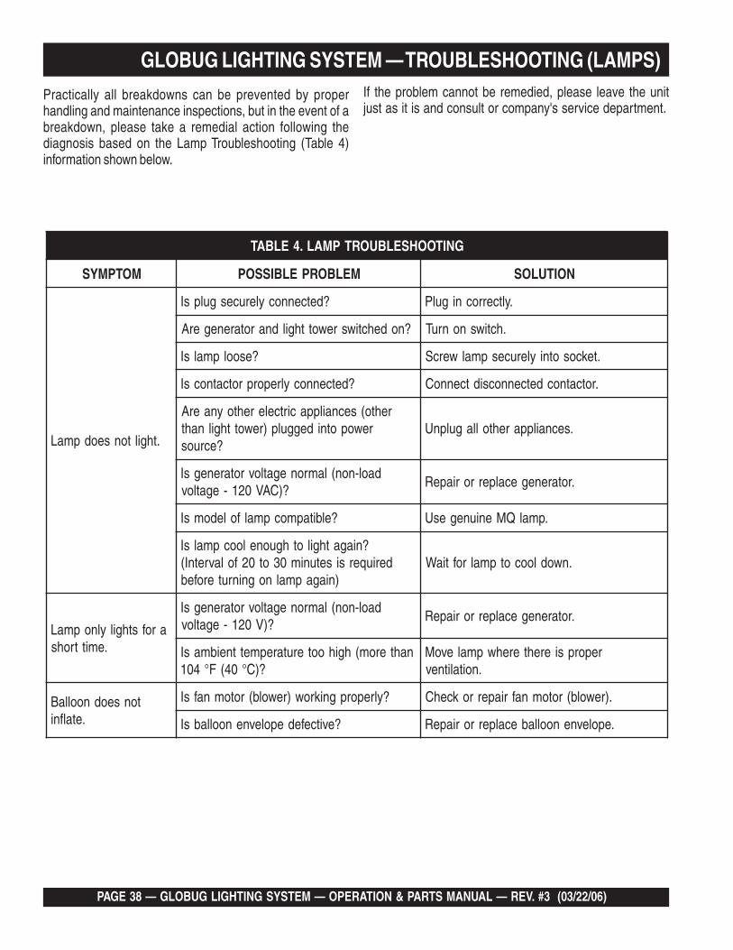
GLOBUG LIGHTING SYSTEM — TROUBLESHOOTING (LAMPS)Practically all breakdowns can be prevented by properhandling and maintenance inspections, but in the event of abreakdown, please take a remedial action following thediagnosis based on the Lamp Troubleshooting (Table 4)information shown below.
If the problem cannot be remedied, please leave the unitjust as it is and consult or company's service department.
GNITOOHSELBUORTPMAL.4ELBAT
MOTPMYS MELBORPELBISSOP NOITULOS
.thgiltonseodpmaL
?detcennocylerucesgulpsI .yltcerrocnigulP
?nodehctiwsrewotthgildnarotarenegerA .hctiwsnonruT
?esoolpmalsI .tekcosotniylerucespmalwercS
?detcennocylreporprotcatnocsI .rotcatnocdetcennocsidtcennoC
rehto(secnailppacirtcelerehtoynaerArewopotnideggulp)rewotthgilnaht
?ecruos.secnailpparehtollagulpnU
daol-non(lamronegatlovrotarenegsI?)CAV021-egatlov
.rotarenegecalperroriapeR
?elbitapmocpmalfoledomsI .pmalQMeniunegesU
?niagathgilothguoneloocpmalsIderiuqersisetunim03ot02folavretnI(
)niagapmalnogninruterofeb.nwodloocotpmalroftiaW
arofsthgilylnopmaL.emittrohs
daol-non(lamronegatlovrotarenegsI?)V021-egatlov
.rotarenegecalperroriapeR
nahterom(hgihooterutarepmettneibmasI?)C°04(F°401
reporpsierehterehwpmalevoM.noitalitnev
tonseodnoollaB.etalfni
?ylreporpgnikrow)rewolb(rotomnafsI .)rewolb(rotomnafriaperrokcehC
?evitcefedepolevnenoollabsI .epolevnenoollabecalperroriapeR

GLOBUG LIGHTING SYSTEM — OPERATION & PARTS MANUAL — REV. #3 (03/22/06) — PAGE 39
GLOBUG LIGHTING SYSTEM — TROUBLESHOOTING (MAST)Practically all breakdowns can be prevented by properhandling and maintenance inspections, but in the event of abreakdown, please take a remedial action following thediagnosis based on the Mast Troubleshooting (Table 5)information shown below.
If the problem cannot be remedied, please leave the unitjust as it is and consult or company's service department.
GNITOOHSELBUORTTSAM.5ELBAT
MOTPMYS MELBORPELBISSOP NOITULOS
ebtonnactsaM.desiar
?tsamnithguacelbacsI .eerfelbacteS
morfdetcennocsideporeriwfodnesI?hcniw
.hcniwoteporeriwtcennoC
?ylhtoomsedilstsamfoecafrusseoD .tsamfoecafrusgnidilsotesaergylppA
gnimocspeektsaM.nwod
?ylreporpgninoitcnufhctalhcniwsI .ylreporpgninoitcnuftonfitrapecalpeR
?esooltfahsmardsI .noitarepostikcehcdnatfahsmardnethgiT
ebtonnactsamehT.derewol
?ylhtoomsedilstsamfoecafrusseoD .tsamfoecafrusgnidilsotesaergylppA
?thgitdlehhcniwfoksidekarbsIehtevomer,yleruceseldnahhcniwgnidloH
.)riapeR(ylwolstsamrewoldnahctal
?yltcerrockrowreppotsytefasseoDybtsamrewoldnaelttilatsampuhcniW
.)riapeR(tinodaolagnittup

PAGE 40 — GLOBUG LIGHTING SYSTEM — OPERATION & PARTS MANUAL — REV. #3 (03/22/06)
EXPLANATION OF CODE IN REMARKS COLUMNHow to read the marks and remarks used in this parts book.
Items Found In the “Remarks” Column
Serial Numbers-Where indicated, this indicates a serial numberrange (inclusive) where a particular part is used.
Model Number-Where indicated, this shows that thecorresponding part is utilized only with this specific model numberor model number variant.
Items Found In the “Items Number” Column
All parts with same symbol in the number column, *, #, +, %, or>, belong to the same assembly or kit.
The contents of this par tscatalog are subject to changewithout notice.
NOTE
NOTEIf more than one of the samereference number is listed, thelast one listed indicates newest(or latest) part available.

GLOBUG LIGHTING SYSTEM — OPERATION & PARTS MANUAL — REV. #3 (03/22/06) — PAGE 41
GLOBUG LIGHTING SYSTEM — SPARE PARTS
GloBug LIGHTING SYSTEM1 TO 3 UNITS
Qty. P/N Description2 ......... E000009800 .... BULB2 ......... A300033800 .... BALLAST/TRANSFORMER2 ......... A300038400 .... CAPACITOR, 24 μF @480 VDC2 ......... 1800001200 ..... BALLOON CLOTH3 ......... A400038300 .... FILTER 200 (AIR)

PAGE 42 — GLOBUG LIGHTING SYSTEM — OPERATION & PARTS MANUAL — REV. #3 (03/22/06)
GLOBUG LIGHTING SYSTEM — NAMEPLATE AND DECALS

GLOBUG LIGHTING SYSTEM — OPERATION & PARTS MANUAL — REV. #3 (03/22/06) — PAGE 43
NAMEPLATE AND DECALS.
NO. PART NO. PART NAME QTY. REMARKS1 DCL413 DECAL; CAUTION COVER INFORMATION 12 DCL404 DECAL; CAUTION LAMP COVER BUZZER 13 DCL412 DECAL; WARNING, LIFT HANGER 14 DCL416 DECAL; DANGER, ELECTRICAL SHOCK HAZ. 15 DCL417 DECAL; WARNING, BURN HAZARD (LAMP) 16 DCL402 DECAL; CAUTION, REMOVE POWER CORD 17 DCL428 DECAL; MQ LOGO 18 DCL401 DECAL; WINCH UP/DOWN 19 DCL407 DECAL; CAUTION, TIRE PRESSURE 110 DCL400 DECAL; DANGER, ELECTRICAL SHOCK (TIRES) 111 DCL409 DECAL; CAUTION, LAMP INFORMATION 112 DCL406 DECAL; WARNING, ADJ. LEVER HAZARD 113 DCL403 DECAL; DANGER ELECTRIC SHOCK (GLOBUG) 114 DCL411 DECAL; DANGER, GLOBUG INFORMATION 115 DCL405 DECAL; DANGER, ELECTRICAL SHOCK (GND.) 116 DCL414 DECAL; WARNING, OUTRIGGER DEPLOYMENT 117 DCL418 DECAL; DANGER, HIGH VOLTAGE 118 35137 DECAL; WARNING, READ MANUAL 119 NAMEPLATE .................................................................. 1........... CONTACT MQ PARTS DEPT.20 DCL415 DECAL; BURN HAZARD (BALLAST) 121 DCL410 DECAL; DANGER, ELECTRICAL SHOCK (CORDS) 122 DCL408 DECAL; ON/OFF 1
GLOBUG LIGHTING SYSTEM — NAMEPLATE AND DECALS

PAGE 44 — GLOBUG LIGHTING SYSTEM — OPERATION & PARTS MANUAL — REV. #3 (03/22/06)
GLOBUG LIGHTING SYSTEM — T-HANDLE ASSY.T-HANDLE ASSY.

GLOBUG LIGHTING SYSTEM — OPERATION & PARTS MANUAL — REV. #3 (03/22/06) — PAGE 45
GLOBUG LIGHTING SYSTEM — T-HANDLE ASSY.T-HANDLE ASSY.
NO. PART NO. PART NAME QTY. REMARKS1* 1102700130 HANDLE GRIP 22 A200016500 HANDLE GRIP ...............................................2 ........... INCLUDES ITEM W/*3 0040730000 SNAP RING (30) 14 1503300130 SLEEVE BEARING (30dx34Dx20) 25 A100012500 BASE PLATE 1

PAGE 46 — GLOBUG LIGHTING SYSTEM — OPERATION & PARTS MANUAL — REV. #3 (03/22/06)
GLOBUG LIGHTING SYSTEM — STEERING ASSY.
STEERING ASSY.

GLOBUG LIGHTING SYSTEM — OPERATION & PARTS MANUAL — REV. #3 (03/22/06) — PAGE 47
STEERING ASSY.
NO. PART NO. PART NAME QTY. REMARKS1 0010510025 BOLT AND WASHER (M10X25) 42 A400033400 CATCHER (OUTRIGGER) 23 A300029800 FRONT SHAFT (R) 14 0040720000 SNAP RING (20) 85 1003000100 TIRE ASSY (4.10/3.50-5) 46 1003000240 TIRE TUBE (4.10/3.50-5) 47 0010308030 BOLT (M8x30) SUS 18 A400034400 LINK (STEERING) 19 0040112041 WASHER (12dx40Dx3.2t) 110 0010512025 BOLT & WASHER (M12x25) 111 0030208000 SELF LOCK NUT (M8) 112 0040108000 WASHER (M8) 513 1504120130 WASHER (12.5dx18Dx0.5t) 814 0040112000 WASHER (M12) 115 2001120310 LINK (HANDLE) 116 1521120130 BOLT (M12x75) LEFT SCREW 117 2071214010 BRAKE 218 1503180130 SLEEVE BEARING (18dx20Dx20) 219 2071213210 BRAKE SHAFT 120 0030108000 NUT (M8) 221 1041000131 SPRING (BRAKE) 122 0010112075 BOLT (M12x75) 123 0030808000 PUSH NUT (8) 324 2001200312 BRAKE PEDAL 125 A300029900 LINK (FRONT SHAFT) 126 A300029701 FRONT SHAFT (L) 1
GLOBUG LIGHTING SYSTEM — STEERING ASSY.

PAGE 48 — GLOBUG LIGHTING SYSTEM — OPERATION & PARTS MANUAL — REV. #3 (03/22/06)
GLOBUG LIGHTING SYSTEM — OUTRIGGER ASSY.OUTRIGGER ASSY.

GLOBUG LIGHTING SYSTEM — OPERATION & PARTS MANUAL — REV. #3 (03/22/06) — PAGE 49
GLOBUG LIGHTING SYSTEM — OUTRIGGER ASSY.
OUTRIGGER ASSY.
NO. PART NO. PART NAME QTY. REMARKS1 0010116090 BOLT (M16x90) 22 A100011600 BRACKET (OUT,R) R 13 0010510025 BOLT & WASHER (M10x25) 104 1501160111 SPACER (OUT,R) 25 A200015302 OUTRIGGER R ............................................ 1 ............. INCLUDES ITEM W/*6 A200015202 OUTRIGGER L .............................................1 ............. INCLUDES ITEM W/*7* 1641000330 RUBBER FOOT 28 0040110000 WASHER (M10) 49 1501100430 SPACER (10.2dx13.8Dx6.5L) 210 0030210000 SELF LOCK NUT (M10) 211 0040116000 WASHER (M16) 212 0040216000 SPRING WASHER (M16) 213 0030116000 NUT (M16) 214 2031321113 WEIGHT (OUT,R) R 115 A100011500 BRACKET (OUT,R) L 116 2031320213 WEIGHT (OUT,R) L 117 A400033400 CATCHER (OUTRIGGER) 2

PAGE 50 — GLOBUG LIGHTING SYSTEM — OPERATION & PARTS MANUAL — REV. #3 (03/22/06)
GLOBUG LIGHTING SYSTEM — MAST ADAPTER ASSY.MAST ADAPTER ASSY.

GLOBUG LIGHTING SYSTEM — OPERATION & PARTS MANUAL — REV. #3 (03/22/06) — PAGE 51
MAST ADAPTER ASSY.
NO. PART NO. PART NAME QTY. REMARKS1 2202390100 STAND ASSY. ................................................1 ........... INCLUDES ITEMS W/*2* 2202390111 STAND 13* 2202500130 SHAFT (STAND) 14 2202500230 SPACER (STAND) 15 1502280130 WASHER 16* 2202520110 COVER (SPRING) 27* 1043002030 SPRING (STAND) L 18* 1043002130 SPRING (STAND) R 19* A400038800 GRIP SHAFT 110* 0011808025 BUTTON BOLT & WASHER (M8 X 25) 411* 0011708010 BUTTON BOLT (M8 X10) 1
GLOBUG LIGHTING SYSTEM — MAST ADAPTER ASSY.

PAGE 52 — GLOBUG LIGHTING SYSTEM — OPERATION & PARTS MANUAL — REV. #3 (03/22/06)
GLOBUG LIGHTING SYSTEM — MAIN MAST ASSY.
MAIN MAST ASSY.

GLOBUG LIGHTING SYSTEM — OPERATION & PARTS MANUAL — REV. #3 (03/22/06) — PAGE 53
GLOBUG LIGHTING SYSTEM — MAIN MAST ASSY.MAIN MAST ASSY.
NO. PART NO. PART NAME QTY. REMARKS1 0020305008 SCREW AND WASHER 42 0010510025 BOLT & WASHER (M10x25) 103 1011000701 WINCH HM-G103 14 A100012401 FIRST MAST 15 0030112000 NUT (M12) 16 0040212000 SPRING WASHER (M12) 17 0040112000 WASHER (M12) 18 1642001430 GROMMET 19 1052001710 HANGER 110 1711080130 SHACKLE 211 0040112041 WASHER (12dx40Dx3.2t) 112 GB0010112040 BOLT (M12x40) 113 0020304012 SCREW & WASHER (M4x12) 314 A200016801 SWITCH COVER 115 2002500430 BOLT (SUPPORT) (MK-440) ......................1 ............. GROUND STUD16 0020104020 SCREW (M4x20) 217 1400200400 SWITCH 118 A300028800 CABLE, MAIN POWER 1
PAGE 54 — GLOBUG LIGHTING SYSTEM — OPERATION & PARTS MANUAL — REV. #3 (03/22/06)
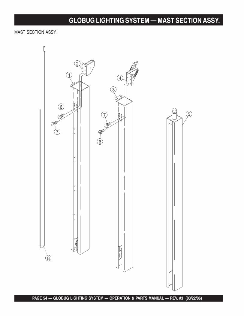
GLOBUG LIGHTING SYSTEM — MAST SECTION ASSY.
MAST SECTION ASSY.

GLOBUG LIGHTING SYSTEM — OPERATION & PARTS MANUAL — REV. #3 (03/22/06) — PAGE 55
GLOBUG LIGHTING SYSTEM — MAST SECTION ASSY.
MAST SECTION ASSY.
NO. PART NO. PART NAME QTY. REMARKS1 2072050112 SECOND MAST 12 2002262010 BRACKET (PULLEY) ................................1 ........... MAST SECTION 23 2082090112 THIRD MAST 14 2012263010 BRACKET (PULLEY) ................................1 ........... MAST SECTION 35 A300034300 FOURTH MAST 16 0020204006 SCREW (M4x6) 67 0020204010 SCREW (M4x10) 68 1031040211 WIRE (4Dx6300L) 1

PAGE 56 — GLOBUG LIGHTING SYSTEM — OPERATION & PARTS MANUAL — REV. #3 (03/22/06)
GLOBUG LIGHTING SYSTEM — BASEPLATE COVER ASSY.
BASEPLATE COVER ASSY.

GLOBUG LIGHTING SYSTEM — OPERATION & PARTS MANUAL — REV. #3 (03/22/06) — PAGE 57
GLOBUG LIGHTING SYSTEM — BASEPLATE COVER ASSY.
BASEPLATE COVER ASSY.
NO. PART NO. PART NAME QTY. REMARKS1 A200016100 COVER (BALLAST) CP 12 A200017901 GUARD (BALLAST) 13 0011808025 BUTTON SCREW & WASHER (M8x25) 64 A400041100 STOPPER 45 0010112025 BOLT (M12x25) 46 0030110000 NUT (M10) 47 0040212000 SPRING WASHER (M12) 48 0040112000 WASHER (M12) 49 A300034600 BRACKET CP 410 E000010600 SCREW (M10x25) 411 0010512020 BOLT & WASHER (M12x20) 412 0030152000 WING NUT (M12) 413 0040110000 WASHER (M10) 414 0040210000 SPRING WASHER (M10) 4

PAGE 58 — GLOBUG LIGHTING SYSTEM — OPERATION & PARTS MANUAL — REV. #3 (03/22/06)
GLOBUG LIGHTING SYSTEM — BALLAST ASSY.BALLAST ASSY.

GLOBUG LIGHTING SYSTEM — OPERATION & PARTS MANUAL — REV. #3 (03/22/06) — PAGE 59
GLOBUG LIGHTING SYSTEM — BALLAST ASSY.BALLAST ASSY.
NO. PART NO. PART NAME QTY. REMARKS1 A300038400 CAPACITOR, 24 μF @ 480 VDC 12 0020304012 SCREW & WASHER (M4x12) 23 A200018200 HOLDER 14 0010508025 BOLT & WASHER (M8x25) 45 A300033901 BALLAST HOLDER 16 A300033800 BALLAST (TRANSFORMER) CP 17 A300035200 CABLE (BALLAST) CP 18 0020305090 SCREW (M5x90) 49 0040105000 WASHER 810 0030105000 NUT 4

PAGE 60 — GLOBUG LIGHTING SYSTEM — OPERATION & PARTS MANUAL — REV. #3 (03/22/06)
GLOBUG LIGHTING SYSTEM — FAN BLOWER/LAMP BASE ASSY.FAN BLOWER/LAMP BASE ASSY.

GLOBUG LIGHTING SYSTEM — OPERATION & PARTS MANUAL — REV. #3 (03/22/06) — PAGE 61
GLOBUG LIGHTING SYSTEM — FAN BLOWER/LAMP BASE ASSY.FAN BLOWER/LAMP BASE ASSY.
NO. PART NO. PART NAME QTY. REMARKS1 A300033700 CABLE 2 (BALLOON) CP 12 A300033600 CABLE 1 (BALLOON) CP 13 A400038900 COVER (WIRE) 14 E000011900 COVER 15 0020305050 SCREW & WASHER (M5x60) 36 A300033500 FAN MOTOR CP 17 0020404008 SCREW (M4x8) 98 A200017702 FAN SUPPORT 19 A400037400 GUARD (FAN) 110 0020405008 SCREW (M5x8) 411 0020204030 SCREW (M4x30) 212 1400150310 MICRO SWITCH COVER 113 1400150210 MICRO SWITCH 114 1400150410 MICRO SWITCH CAP (SENSOR) 115 0040104000 WASHER (M4) 216 0030104000 NUT (M4) 517 E000010500 BUZZER 118 A400038600 BRACKET (BUZZER) 119 A100013301 FLANGE 120 0021710025 SET SCREW (M10x25) 121 E000010400 CABLE CLAMP 122 2204500130 SEAL (NORMAL) 123 1800001100 SHEET (BOTTOM) 124 2204500230 PACKING 125 A300034400 PLATE (BOTTOM) 126 0011808025 BUTTON SCREW & WASHER (M8x25) 827 E000009700 WAVE WASHER (M5) 328 A400030700 STOPPER (FILTER) CP 329 E000009900 SPACER 330 A200018000 PLATE (AIR) 131 A400038300 FILTER 200 (AIR) 1

PAGE 62 — GLOBUG LIGHTING SYSTEM — OPERATION & PARTS MANUAL — REV. #3 (03/22/06)
GLOBUG LIGHTING SYSTEM — BALLOON/LAMP GUARD ASSY.BALLOON/LAMP GUARD ASSY.
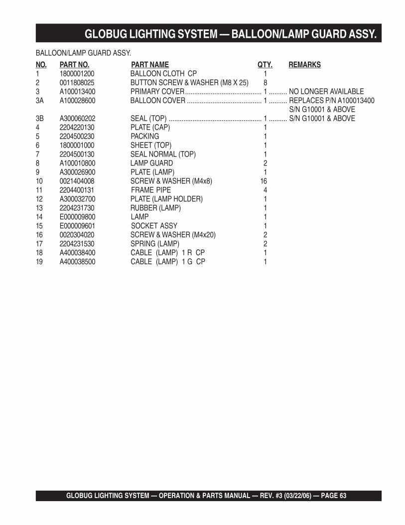
GLOBUG LIGHTING SYSTEM — OPERATION & PARTS MANUAL — REV. #3 (03/22/06) — PAGE 63
GLOBUG LIGHTING SYSTEM — BALLOON/LAMP GUARD ASSY.BALLOON/LAMP GUARD ASSY.
NO. PART NO. PART NAME QTY. REMARKS1 1800001200 BALLOON CLOTH CP 12 0011808025 BUTTON SCREW & WASHER (M8 X 25) 83 A100013400 PRIMARY COVER.......................................... 1 .......... NO LONGER AVAILABLE3A A100028600 BALLOON COVER ......................................... 1 .......... REPLACES P/N A100013400
S/N G10001 & ABOVE3B A300060202 SEAL (TOP) ................................................... 1 .......... S/N G10001 & ABOVE4 2204220130 PLATE (CAP) 15 2204500230 PACKING 16 1800001000 SHEET (TOP) 17 2204500130 SEAL NORMAL (TOP) 18 A100010800 LAMP GUARD 29 A300026900 PLATE (LAMP) 110 0021404008 SCREW & WASHER (M4x8) 1611 2204400131 FRAME PIPE 412 A300032700 PLATE (LAMP HOLDER) 113 2204231730 RUBBER (LAMP) 114 E000009800 LAMP 115 E000009601 SOCKET ASSY 116 0020304020 SCREW & WASHER (M4x20) 217 2204231530 SPRING (LAMP) 218 A400038400 CABLE (LAMP) 1 R CP 119 A400038500 CABLE (LAMP) 1 G CP 1

PAGE 64 — GLOBUG LIGHTING SYSTEM — OPERATION & PARTS MANUAL — REV. #3 (03/22/06)
Effective: October 1, 2002 TERMS AND CONDITIONS OF SALE — PARTS
PAYMENT TERMS
Terms of payment for parts are net 30 days.
FREIGHT POLICY
All parts orders will be shipped collect orprepaid with the charges added to the invoice.All shipments are F.O.B. point of origin.Multiquip’s responsibility ceases when a signedmanifest has been obtained from the carrier,and any claim for shortage or damage must besettled between the consignee and the carrier.
MINIMUM ORDER
The minimum charge for orders from Mul-tiquip is $15.00 net. Customers will be askedfor instructions regarding handling of ordersnot meeting this requirement.
RETURNED GOODS POLICY
Return shipments will be accepted and creditwill be allowed, subject to the following provi-sions:
1. A Returned Material Authorization mustbe approved by Multiquip prior to ship-ment.
2. To obtain a Return Material Authorization,a list must be provided to Multiquip PartsSales that defines item numbers, quanti-ties, and descriptions of the items to bereturned.
a. The parts numbers and descriptionsmust match the current parts pricelist.
b. The list must be typed or computergenerated.
c. The list must state the reason(s) forthe return.
d. The list must reference the salesorder(s) or invoice(s) under which theitems were originally purchased.
e. The list must include the name andphone number of the person request-ing the RMA.
3. A copy of the Return Material Authoriza-tion must accompany the return shipment.
4. Freight is at the sender’s expense. Allparts must be returned freight prepaid toMultiquip’s designated receiving point.
5. Parts must be in new and resalable con-dition, in the original Multiquip package (ifany), and with Multiquip part numbersclearly marked.
6. The following items are not returnable:
a. Obsolete parts. (If an item is in theprice book and shows as being re-placed by another item, it is obsolete.)
b. Any parts with a limited shelf life(such as gaskets, seals, “O” rings,and other rubber parts) that were pur-chased more than six months prior tothe return date.
c. Any line item with an extended dealernet price of less than $5.00.
d. Special order items.
e. Electrical components.
f. Paint, chemicals, and lubricants.
g. Decals and paper products.
h. Items purchased in kits.
7. The sender will be notified of any materialreceived that is not acceptable.
8. Such material will be held for five workingdays from notification, pending instruc-tions. If a reply is not received within fivedays, the material will be returned to thesender at his expense.
9. Credit on returned parts will be issued atdealer net price at time of the originalpurchase, less a 15% restocking charge.
10. In cases where an item is accepted, forwhich the original purchase documentcan not be determined, the price will bebased on the list price that was effectivetwelve months prior to the RMA date.
11. Credit issued will be applied to futurepurchases only.
PRICING AND REBATES
Prices are subject to change without priornotice. Price changes are effective on a spe-cific date and all orders received on or after thatdate will be billed at the revised price. Rebatesfor price declines and added charges for priceincreases will not be made for stock on handat the time of any price change.
Multiquip reserves the right to quote and selldirect to Government agencies, and to Origi-nal Equipment Manufacturer accounts whouse our products as integral parts of their ownproducts.
SPECIAL EXPEDITING SERVICE
A $35.00 surcharge will be added to the invoicefor special handling including bus shipments,insured parcel post or in cases where Multiquipmust personally deliver the parts to the carrier.
LIMITATIONS OF SELLER’S LIABILITY
Multiquip shall not be liable hereunder fordamages in excess of the purchase price of theitem with respect to which damages areclaimed, and in no event shall Multiquip beliable for loss of profit or good will or for anyother special, consequential or incidental dam-ages.
LIMITATION OF WARRANTIES
No warranties, express or implied, are madein connection with the sale of parts or tradeaccessories nor as to any engine not manufac-tured by Multiquip. Such warranties made inconnection with the sale of new, complete unitsare made exclusively by a statement of war-ranty packaged with such units, and Multiquipneither assumes nor authorizes any person toassume for it any other obligation or liabilitywhatever in connection with the sale of itsproducts. Apart from such written statement ofwarranty, there are no warranties, express,implied or statutory, which extend beyond thedescription of the products on the face hereof.

GLOBUG LIGHTING SYSTEM — OPERATION & PARTS MANUAL — REV. #3 (03/22/06) — PAGE 65
NOTE PAGE

OPERATION & PARTS MANUAL
MULTIQUIP INC.....18910 WILMINGTON AVE.CARSON, CALIFORNIA 90746800-421-1244 • 310-537-3700FAX: 310-537-3927E-mail:[email protected]:multiquip.comAtlanta • Boise • Dallas • Houston • NewarkMontreal, Canada • Manchester, UKRio De Janiero, Brazil • Guadalajara, Mexico
Your Local Dealer is:
HERE'S HOW TO GET HELPPLEASE HAVE THE MODEL AND SERIAL
NUMBER ON-HAND WHEN CALLINGMULTIQUIP CORPORATE OFFICE18910 Wilmington Ave. 800-421-1244Carson, CA 90746 FAX: 310-537-3927
PARTS DEPARTMENT800-427-1244 FAX: 800-672-7877310-537-3700 FAX: 310-637-3284
MAYCO PARTS800-306-2926 FAX: 800-672-7877310-537-3700 FAX: 310-637-3284
SERVICE DEPARTMENT800-478-1244 FAX: 310-537-4259310-537-3700
TECHNICAL ASSISTANCE800-478-1244 FAX: 310-631-5032
WARRANTY DEPARTMENT800-421-1244, EXT. 279 FAX: 310-537-1173310-537-3700, EXT. 279