GLOBALJIG INTERNATIONAL S.r.l. - Chief Automotive INTERVENTIONS ... The company GLOBALJIG...
57
Transcript of GLOBALJIG INTERNATIONAL S.r.l. - Chief Automotive INTERVENTIONS ... The company GLOBALJIG...


GLOBALJIG INTERNATIONAL S.r.l.
3
Index 1. USE AND STORAGE OF THE
INSTALLATION, USE AND MAINTENANCE MANUAL........................................................................... 4 1.1. Purposes and intended users of the Installation, Use and Maintenance manual .................................................................4 1.2. Definitions and terminology...................................................................................................................................................4 1.3. Structure of the manual.........................................................................................................................................................5 1.4. Storing the manual ................................................................................................................................................................6 1.5. Updating................................................................................................................................................................................6
2. GENERAL DESCRIPTION ........................................................................................................................ 7 2.1. Encumbrance dimensions of the lifting platform ...................................................................................................................7 2.2. User.......................................................................................................................................................................................7 2.3. Consignment .........................................................................................................................................................................7 2.4. Identification of the various versions.....................................................................................................................................8 2.5. Potential and limitations for the lifting platform......................................................................................................................8 2.6. Lifting platform orientation.....................................................................................................................................................9 2.7. Operating modes.................................................................................................................................................................10 2.8. Safety devices.....................................................................................................................................................................10 2.9. Operating indications and instructions ................................................................................................................................10
3. TECHNICAL DESCRIPTION OF THE LIFTING PLATFORM ................................................................. 11 3.1. General information.............................................................................................................................................................11 3.2. Identification of the parts .....................................................................................................................................................11 3.3. Technical description ..........................................................................................................................................................12
4. INSTALLATION OF THE LIFTING PLATFORM..................................................................................... 14 4.1. Transport and handling .......................................................................................................................................................14 4.2. Storage ...............................................................................................................................................................................14 4.3. Application of the towing arm..............................................................................................................................................16 4.4. Towing arm operating positions ..........................................................................................................................................17 4.5. Lifting platform installation and work area...........................................................................................................................18 4.6. Foreseen environmental operating conditions ....................................................................................................................19 4.7. Installation characteristics ...................................................................................................................................................19 4.8. System connections............................................................................................................................................................20 4.9. Commissioning the Koala lifting platform............................................................................................................................20
5. INSTRUCTIONS FOR USE ..................................................................................................................... 21 5.1. Introductory notes ...............................................................................................................................................................21 5.2. Command and control devices............................................................................................................................................21 5.3. Operating procedures .........................................................................................................................................................22 5.4. Adjustments ........................................................................................................................................................................23
6. SAFETY RELATED DEVICES ................................................................................................................ 24 6.1. Introduction .........................................................................................................................................................................24 6.2. Protection devices...............................................................................................................................................................24 6.3. Residual risks......................................................................................................................................................................24
7. MAINTENANCE INTERVENTIONS......................................................................................................... 25 7.1. Introductory notes ...............................................................................................................................................................25 7.2. Customer assistance service ..............................................................................................................................................25 7.3. Routine maintenance ..........................................................................................................................................................25
7.3.1 Cleaning the lifting platform .......................................................................................................................................25 7.3.2 Checking the efficiency of the safety catch................................................................................................................26
7.4. Breakdowns or malfunctions...............................................................................................................................................26 7.5. Special Maintenance...........................................................................................................................................................26
8. SPARE PARTS INFORMATION ............................................................................................................. 27 8.1. General information.............................................................................................................................................................27 8.2. Components recommended to keep in stock......................................................................................................................27
9. INSTRUCTIONS FOR DISMANTLING AND DISPOSING OF THE LIFTING PLATFORM..................... 28 9.1. Removing the connections of the lifting platform ................................................................................................................28 9.2. Preparing the lifting platform for handling and transport .....................................................................................................28 9.3. Disposal of the lifting platform.............................................................................................................................................28
10. ANNEXES................................................................................................................................................ 29 10.1. List of Annexes ...................................................................................................................................................................29
11. MACHINE LOG BOOK............................................................................................................................ 53

GLOBALJIG INTERNATIONAL S.r.l.
4
1 USE AND STORAGE OF THE INSTALLATION, USE AND MAINTENANCE MANUAL
Note: Within this document, the term LP is used to refer to the KOALA car lifting platform.
1.1 Purposes and intended users of the Installation, Use and Maintenance manual The Installation, Use and Maintenance Manual provides the necessary indications for the correct use of the KOALA LP and describes its physical and functional characteristics. The manual must remain with the LP for its entire life cycle. For this reason, in the event of resale to any third party, the manual must accompany the machine in order to ensure the safety of the operator and the user. The manual allows for the performance of the following operations:
INSTALLATION
USE
MAINTENANCE
DISPOSAL It is intended for use by both the user, as well as by the operators in charge of the operations above. Where required, the necessary qualifications are provided in section 1.2. The company GLOBALJIG INTERNATIONAL shall bear no responsibility for any personal injury or property damage resulting from the non-observance of the requirements contained within this manual. The company GLOBALJIG INTERNATIONAL shall also bear no responsibility for any risks which may arise in relation to any of the following situations:
improper use of the LP;
use which does not comply with the specific national standard;
installation which does not comply with the indications contained within this document;
lack of required maintenance;
unauthorised modifications or interventions;
use of non-original or non-specific spare parts;
non-observance of the instructions contained within this document.
The manual can no longer constitute a reference in the event that the user should intend to perform any modifications which will alter the configuration of the LP. In such cases, the manufacturer shall only bear responsibility in relation to any eventual manufacturing defects.
1.2 Definitions and terminology
User
Operator
LP lifting platform
The term “User” refers to any individual whose responsibilities involve the continuous use of the LP.
The term “Operators” refers to the individuals in charge of installing, operating, adjusting, servicing, cleaning and repairing the LP.

GLOBALJIG INTERNATIONAL S.r.l.
5
The reader of this document must interpret the term “Manual”, in relation to the KOALA LP, as a reference to this Installation, Use and Maintenance Manual. The operations described in section 1.1 must be performed by personnel who are qualified for the specific tasks. The qualification level refers to the activities for which the operator is authorised according to the manufacturer’s indications.
Qualification 1 The personnel classified under this qualification level have not received specific training, but are authorised to perform simple operations inherent to the use of the LP. This qualification authorises the operator to perform installation, adjustment, routine maintenance and special maintenance interventions.
Qualification 2 Personnel with specific training for the performance of electrical interventions. This qualification authorises the operator to perform installation, adjustment, routine maintenance and special maintenance interventions. The training activities inherent to the operations listed above are carried out through training courses with GLOBALJIG Technicians, as well as through the in-depth study of this manual.
Qualification 3 Personnel with specific training regarding electronically assisted Automatic Machinery, in charge of performing electrical interventions. This qualification authorises the operator to perform installation, adjustment, routine maintenance and special maintenance interventions. The training activities inherent to the operations listed above are carried out through training courses with GLOBALJIG Technicians, as well as through the in-depth study of this manual. To this end, the operator must be trained, through the careful study of this Installation, Use and Maintenance Manual, for the use of the controls found on the KOALA’s control unit. The manual contains notes which serve to draw the user’s/operator’s attention to a specific procedure or particular operation.
Three types of notes can be found:
NOTE: these are warnings which serve to guide and optimise the operator’s actions, or else to better highlight certain characteristics of the KOALA.
ATTENTION: these are extremely important warnings which specify actions to be performed/avoided, or else certain precautions to be taken, prior to using the KOALA, in order to avoid damaging the LP itself.
DANGER: these are extremely important warnings which specify actions to be performed/avoided, or else certain precautions to be taken, prior to using the KOALA, in order to avoid personal injury.
1.3 Structure of the manual This manual has been drawn up based on the indications deriving from the Machinery Directive (89/392) and the standards referred to therein. The manual is structured with:
- A data plate identification page (correlated to the specific lifting platform).
- An Index.
- Annexed documentation.

GLOBALJIG INTERNATIONAL S.r.l.
6
1.4 Storing the manual The KOALA LP’s Installation, Use and Maintenance Manual must be available to the user at all times. For this reason, it must be stored in an appropriate location in the vicinity of the machine, in order to allow for the correct performance of the activities in relation to the LP. The Installation, Use and Maintenance Manual must be stored in a location which is protected against heat, humidity and/or any other potentially harmful environmental conditions. The integrity of the Installation, Use and Maintenance Manual is necessary in order to guarantee accurate knowledge of the LP’s characteristics. Its contents must therefore be verified based on that which is indicated in the index. In the event that the manual should be lost or irreparably damaged, a duplicate copy may be requested from the company GLOBALJIG INTERNATIONAL.
1.5 Updating In the event that an updated version of the Installation, Use and Maintenance Manual should be issued, the manufacturer will not be obliged to update this document, save for the case that any indications have been added which may limit the dangers associated with the use of the LP itself.
GLOBALJIG INTERNATIONAL S.r.l.
7
2 GENERAL DESCRIPTION
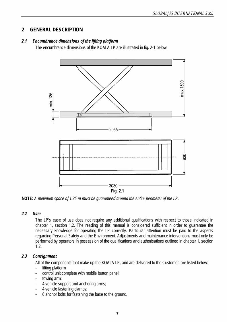
2.1 Encumbrance dimensions of the lifting platform The encumbrance dimensions of the KOALA LP are illustrated in fig. 2-1 below.
Fig. 2.1
NOTE: A minimum space of 1.35 m must be guaranteed around the entire perimeter of the LP.
2.2 User The LP’s ease of use does not require any additional qualifications with respect to those indicated in chapter 1, section 1.2. The reading of this manual is considered sufficient in order to guarantee the necessary knowledge for operating the LP correctly. Particular attention must be paid to the aspects regarding Personal Safety and the Environment. Adjustments and maintenance interventions must only be performed by operators in possession of the qualifications and authorisations outlined in chapter 1, section 1.2.
2.3 Consignment All of the components that make up the KOALA LP, and are delivered to the Customer, are listed below: - lifting platform - control unit complete with mobile button panel; - towing arm; - 4 vehicle support and anchoring arms; - 4 vehicle fastening clamps; - 6 anchor bolts for fastening the base to the ground.

GLOBALJIG INTERNATIONAL S.r.l.
8
2.4 Identification of the various versions The KOALA LP is manufactured in various versions, distinguished by the type of electrical power supply to which they must be connected. The various versions include:
- - 220 / 400 V - 50 / 60 Hz tri-phase
- - 200 V - 50 / 60 Hz tri-phase
2.5 Potential and limitations for the lifting platform
- Max. capacity: .................................................................................................... 2500 kg.
- Oil tank: ......................................................................................................................6 L.
- Max hydraulic pressure (with a load of 2500 kg): .................................................330 bar.
- Electrical power supply: ........................................... based on the version (see sec. 2.4)
- Electrical consumption: ......................................................................................1.85 kW.
- Compressed air supply: .....................................................................................6 - 8 bar.
- Lifting time: ........................................................................................................... 55 sec.
- Lowering time:....................................................................................................... 50 sec.
- Maximum travel height: .................................................................................... 1520 mm.
- Average sound level: ......................................................................................<70 dB (A).
- Lift dimensions:
length: ................................................................................................... 3030 mm.
max. length with towing arm: ................................................................. 4065 mm.
width: ....................................................................................................... 930 mm.
max. width with support brackets: ......................................................... 1878 mm.
maximum LP height:............................................................................... 1500 mm.
- Max. height with towing arm: ............................................................... 3590 mm.
- Arm dimensions:
height (with wheels): .............................................................................. 2166 mm.
length: ................................................................................................... 1395 mm.
width: ....................................................................................................... 505 mm.
- Control unit dimensions:
length: ..................................................................................................... 340 mm.
width: ....................................................................................................... 320 mm.
height: ..................................................................................................... 850 mm.
- LP weight with accessories: ................................................................................. 910 kg.
- Control unit weight: ................................................................................................ 41 kg.
- LP accessories: .................................................................................................... 246 kg.
- Complete towing arm: .......................................................................................... 230 kg.

GLOBALJIG INTERNATIONAL S.r.l.
9
2.6 “KOALA” lift orientation
The front of the lift (as indicated in the diagram) is the side containing the “lifting jacks” and the outlet for
the connections to the control unit.
Always position the heaviest portion of the load toward the front of the lift, as this will ensure the
maximum stability of the platform.
ATTENTION:
The LP is designed for the heaviest part of the load to be sustained at the front.
FRONT
HYDRAULIC JACKS

GLOBALJIG INTERNATIONAL S.r.l.
10
2.7 Operating modes The KOALA LP is designed for manual operation. It therefore requires the operator to perform simple lifting, lowering and stopping operations using the appropriate button panel. Operating conditions which could compromise the safety of the LP’s operators are not foreseen nor expected.
2.8 Safety devices The KOALA LP is designed and manufactured in compliance with the current applicable European Directives and in accordance with the legal regulations deriving from them. The personnel assigned to operating the machine are advised to work in compliance with the prescribed methods and with particular care with regards to their individual responsibilities. In the event that any situations should arise which are not foreseen by this manual, it is recommended to contact GLOBALJIG’s Technical Assistance Service before proceeding. Should this recommendation not be observed, GLOBALJIG will decline any responsibility for any unforeseeable improper use of the machine. The topics regarding the safety devices and relative regulations are discussed in detail in chapter 6.
! DANGER ! ! ! GLOBALJIG recommends that the individual activities be performed by one
operator alone, in order to avoid simultaneously exposing more than one operator to the relative risks.
2.9 Operating indications and instructions The electro-hydraulic control unit is furnished with a data plate (illustrated in fig. 2.3) which summarises the most important operating instructions regarding the conduct to be observed by the operator when using the LP itself.
INSTRUCTIONS FOR USE - Read the instruction manual carefully before using the lift and make constant reference to it during use.
- The lift may only be used by properly trained and authorised personnel.
- It is forbidden to use the lift for any purposes other than those which are expressly indicated within the instruction manual.
- Nobody must be permitted to climb upon the load or upon the structure of the lift under any circumstances.
- Make sure that the weight of the vehicle to be lifted and the distribution of the load comply with that which is indicated in the instruction manual.
- It is strictly forbidden to exceed the lift’s maximum capacity.
- Check the stability of the vehicle upon the support structures before and during lifting operations.
- Closely monitor all lifting and lowering operations in order to make sure that no risks of personal injury or property damage arise.
- Closely monitor all lifting and lowering operations in order to make sure that the lift’s movement will not be impeded by the presence of any objects within its immediate area.
- Nobody must be permitted within the lift’s immediate area while it is in function.
- Press the mushroom-head emergency button on the remote control in the event of breakdowns or malfunctions.
- Before performing any interventions upon the lift, set the main switch on the control unit’s control panel to its 0 (door lock) position.
- Any interventions upon the lift’s installed systems must only be performed by professionally qualified personnel.
- The European safety directives forbid any tampering with the machine’s safety devices
Fig. 2.3

GLOBALJIG INTERNATIONAL S.r.l.
11
3 TECHNICAL DESCRIPTION OF THE LIFTING PLATFORM
3.1 General information The KOALA LP is designed and manufactured in consideration of the operational requirements of car body mechanics within working environments like car body repair shops.
3.2 Identification of the parts The locations of the main components which make up the LP are shown in fig. 3.1 (including accessories).
Fig. 3.1
LEGEND 1 Upper frame 8 Vertical arm 2 Base 9 Control unit 3 Lifting arms 10 Control button panel 4 Hydraulic lifting cylinders 11 Wheel support “stools” 5 Vehicle support brackets 12 Lifting pads 6 Vehicle fastening clamps 13 Complete hydraulic assembly 7 Horizontal towing arm

GLOBALJIG INTERNATIONAL S.r.l.
12
3.3 Technical description The KOALA LP is designed and manufactured for lifting vehicles by means of its towing arm in order to allow for the repair of the vehicle’s body work. Its structure provides for the rapid lifting of the vehicle and is ideal for flanking more complete equipment: jig lifts. Physically, the LP is made up of a lower structure, comprised of the base to be fastened to the ground (2, fig. 3.1), an upper structure (1, fig. 3.1.) and two lifting rods (3, fig. 3.1), connected in a scissor-like fashion, which connect the upper frame to the lower frame. The lifting movement is powered by two hydraulic cylinders (4, fig. 3.1), which are controlled by a special electro-hydraulic control unit located inside a structure that also contains the electrical panel and the pneumatic solenoid valve (9, fig. 3.1). The hydraulic control unit is comprised of a motor that controls a hydraulic pump. The oil is located in the appropriate tank. The control unit also contains a pneumatic safety release solenoid valve. The safety catch device intervenes in the event of a hydraulic system malfunction, by mechanically stopping the lift’s descent. When stopping at various heights for work operations, the safety catch device will slide into one of the notches on the base, illustrated in fig. 3.2. The user can press an appropriate button to activate, by means of a solenoid valve, the cylinder that raises the safety catch device (thereby disengaging the safety system). Upon releasing the button, the safety device will automatically be re-activated.
Fig. 3.2: 1) Control cylinder, 2) Safety catch device, 3) Hooking notches, 4) Base, 5) Lifting arm

GLOBALJIG INTERNATIONAL S.r.l.
13
A special electric limit switch acts upon the movement of the lifting arms and deactivates the hydraulic control unit when the platform’s maximum height has been reached. In addition to the previously described safety blocking system, the upper frame of the lift is equipped with two brackets, or support feet, with a special blocking/releasing system (fig. 3.3). When the upper frame is raised off the ground, the bracket rotates into the position illustrated in the diagram. These brackets, or support feet, serve two purposes (platform lowering):
- safety, for protection against the crushing of the lower limbs.
- operational, for the insertion and fastening of the towing arm at an optimal height.
In order to command the complete descent of the lift, the operator must intervene upon the bracket by raising the lift a few centimetres and rotating the two brackets towards the internal portion of the lift until they are in a horizontal position. Finally, the brackets must be pushed towards the outside of the lift until the pin can be inserted in the appropriate slot to lock the bracket in its horizontal position. This system is, however, automatically activated each time the LP reaches the ground.
Safety engaged Safety disengaged Fig. 3.3
If a vehicle is present upon the lift, the operator must disarm the brackets before beginning the descent; in this case, the danger of crushing the lower limbs beneath the upper frame is not present as the vehicle itself protrudes from each side of the frame. The upper frame is made up of rectangular cross-section steel profiles and is appropriately shaped to facilitate the installation of the various accessories (vehicle support brackets and towing arm). The installation operations must be performed by the user, following the indications provided in chapter 4 of this manual; the usage procedures are described in chapter 5. The towing arm is equipped with a hydraulic cylinder, controlled by a pneumo-hydraulic pump, that allows for the vehicle to be towed by means of a chain and hook (13, fig. 3.1). The chain is also equipped with a safety cable in order to prevent personal injury in the event that any of the links should break.
LEGEND 1 Support foot 2 Pin 3 Fastening support with lock/release system

GLOBALJIG INTERNATIONAL S.r.l.
14
4. INSTALLATION OF THE LIFTING PLATFORM
4.1. Transport and handling
The KOALA LP’s packaging elements for transport and handling include the following:
1 wooden pallet containing the LP. Gross weight: approx. 930 kg
1 crate containing the electro-hydraulic control unit. Gross weight: approx. 47 kg
1 crate containing the towing arm and other standard accessories. Gross weight: approx. 500 kg For the handling of the complete consignment, it is necessary to use a forklift with a minimum capacity of 1500 kg. The forklift must have forks of at least 1.5 m in length. The same holds true for the ground-based handling of the LP, once it has been unpacked, as it does not come supplied with any accessories useful for its handling. The hydraulic control unit must likewise be lifted using a forklift, but is equipped with appropriate wheels for ground transport. In order to lift the lifting platform after it has been unpacked, tie the strap as shown in fig. 4.1.
! ! ATTENTION! !
If using a bridge crane for the lifting and handling operations, maximum care must be taken to avoid impacts and jolts, as well as sudden accelerations or decelerations
which could cause the lift to become unbalanced.
4.2. Storage
The LP is designed for storage in environments which meet the following requirements:
- Room temperature between -25°C and + 55°C for prolonged storage periods and -25°C and + 70°C for storage periods of less than 24 hours;
- Relative humidity between 30% and 95% (without condensation). Storage locations which do not meet the above requirements may not be used.

GLOBALJIG INTERNATIONAL S.r.l.
15
4.3.

GLOBALJIG INTERNATIONAL S.r.l.
16
4.3.Application of the towing arm
! ! ATTENTION! ! Before connecting or disconnecting the towing arm, make sure that the horizontal element
is aligned with the articulated element (see photo 1). Failure to respect this indication could result in personal injury or property damage.
- Raise the LP so that the "support feet" are in their vertical position (properly engaged).
- Lower the LP so that it rests upon the "feet" (see photo 2).
- Position the towing arm upon the frame (see photo 3).
- Raise the LP so that the towing arm remains connected to the edge of the frame and the wheels are lifted off the ground (see photo 4).
- Use the two pins (protruding from the side) to manually raise the lower connector until it makes contact with the frame (see photo 5).
- Insert the wedge (with the round profile facing down) into the slot on the right, indicated with the label IN (see photos 6 and 7).
- Use a hammer to firmly block the wedge in place (see photo 8).
Support foot
Photo Photo
Photo Photo
Photo Photo
Photo Photo

GLOBALJIG INTERNATIONAL S.r.l.
17
4.4. Towing arm operating positions
- In order to adjust the position to the right
or left, remove the two pins (see photo 2)
and align the arm (see photo 3) blocking
one of the two connection rods with the
pin (see photo 4).
“Straight" towing position, or rather
perpendicular to the frame (see photo 1).
The two connection rods (A42680) must
be applied as a pair (with the A42704
pins).

GLOBALJIG INTERNATIONAL S.r.l.
18
4.5. Lifting platform installation and work area
The LP’s working position must be determined in consideration of the fact that the hydraulic control unit’s tube for connecting to the LP is 3.5 m in length and connects to the front, on the opposite side to that upon which the vehicles are loaded.
Perform the following connections:
Flexible oil supply tube (unscrew the male / female caps) Air tube Limit switch cable Connect the electrical power supply (230/400 V - 50/60 Hz tri-phase; or 200 V - 50/60 Hz tri-phase) to the
control unit by means of the appropriate socket.
! NOTE ! For the assembly and use of the vehicle support arms
and the other parts to be inserted upon them, see the procedures described in chapter 5.
Support base m. 2.055 x 0.75
Work area encumbrance
measurements
Towing arm
Towing arm

GLOBALJIG INTERNATIONAL S.r.l.
19
4.6. Foreseen environmental operating conditions
The KOALA LP is designed for indoor use. Therefore, the environmental parameters to be used as a reference are the following:
temperature between +5°C and +40°C humidity between 30% and 95% (without condensation)
The LP’s operating environment must also meet the following requirements:
The roof of the structure must be sufficiently high so as to allow for the complete lifting of any vehicle without causing damage. It is recommended to verify this height when it using the lift with special vehicles.
The flooring upon which the lift is installed must be smooth and level (therefore free of any slopes and/or roughness). The unsuitability of the floor’s surface could lead to dangerous situations when working with the LP and when moving the LP upon the floor while loaded.
The LP is not designed for use in environments with characteristics other than those which are described above.
! ! ATTENTION! ! The use of the LP in environments or situations which are not
foreseen within this manual shall exonerate the company GLOBALJIG from any responsibility regarding the use in question.
4.7. Installation characteristics
The KOALA LP must be installed upon perfectly smooth and horizontal flooring (see characteristics on page 37). The LP must be properly fastened to the floor using the 6 supplied anchoring bolts. In order to function properly, the LP must be connected to an external pneumatic and electrical energy supply with the following characteristics:
Electrical power supply provided through an industrial electrical outlet, with a power supply voltage equal to
that which is required for the specific version. Specifically:
240/415 V tri-phase + ground and a frequency of 50 Hz ± 2%; the maximum foreseen consumption is 1.1 kW; the grounding wire must have a minimum cross-section of 2.5 mm²;
200/230 V tri-phase + ground and a frequency of 50/60 Hz ± 2%; the maximum foreseen consumption is 1.1 kW; the grounding wire must have a minimum cross-section of 2.5 mm²;
!!! DANGER !!!
The customer is required to install a three-pole circuit breaker, with a loss sensitivity of 30 mA, upstream from the LP (within the building’s power panel)
in order to ensure that the power supply will be automatically cut off in the event of an isolation failure regarding the LP itself.

GLOBALJIG INTERNATIONAL S.r.l.
20
4.8. System connections
HYDRAULIC: Use two wrenches to remove the caps (male / female) from the fittings of the flexible tubes (A71049 and
A71050) and connect them together (photos 1, 2 and 3). COMPRESSED AIR: Connect the flexible tube (A70178) with the quick connector (A70185), from the control unit, to the tube
from the lift (A70179). Connect tube A70177, complete with it's 1/4" female quick connector fitting A42747, to the compressed
air supply. ELECTRICAL (raising limit switch): Connect the plug and outlet of the cables from the control unit and the lift.
! ! ATTENTION! !
The incorrect or omitted connection of these elements will impede the lift’s ascent functionality for safety reasons.
4.9. Commissioning the Koala lifting platform
After having performed all of the system’s connections as described above, press the raise button on the remote control (fig. 5.1). If the direction of rotation (RST) of the phases is correct, the LP will rise. If the LP does not move and the control unit’s motor “turns”, release the button immediately; the motor’s direction of rotation is incorrect and the pump could be damaged. Invert the plug’s phase wires and repeat the operation.
(Lift) (Lift)
(Control unit)
(Lift) (Control unit)
photophoto
photo

GLOBALJIG INTERNATIONAL S.r.l.
21
5. INSTRUCTIONS FOR USE
5.1. Introductory notes
For its proper use, the KOALA LP requires a single operator in possession of Qualification 1. Given the LP’s functionality type, the operations that the operator is required to perform upon the LP are extremely simple. When using the LP, or rather while vehicle raising and lowering operations are being carried out, the user must always remain at a safe distance (at least 1.5 m) from the LP, controlling its movements from the mobile button panel.
! DANGER ! ! ! While raising and lowering manoeuvres are being carried out,
the above mentioned safety distance will ensure greater operator safety in the event that any objects or the load itself should fall from the LP
! ! ATTENTION! ! GLOBALJIG shall bear no responsibility for any damages
in the event that the instructions contained within this manual are not respected.
! DANGER ! ! ! Before performing any raising or lowering manoeuvres, the operator must
always make sure that at least 50 cm of free space is available between every mobile part of the LP, or the vehicle being lifted,
and the other fixed or mobile surrounding structures.
! DANGER ! ! ! The vehicles to be lifted must not have any people or additional loads on board.
5.2. Command and control devices
The KOALA lift’s command and control devices are illustrated in fig. 5.1 below and are described in the relative legend.
Fig. 5.1
Green indicator light (turns on when the main switch is in its “I” position)
3. Main electrical switch
Emergency button
6. Raise button
5. Lower button Safety deactivation button

GLOBALJIG INTERNATIONAL S.r.l.
22
5.3. Operating procedures
The regular operating procedures that the user must perform upon the LP are described below. a. Start up - Check the control unit’s compressed air supply. - Check the compressed air supply connection between the control unit and the LP. - Check the control unit’s electrical power supply. - Sets the main switch to its «I» position and check that the green light turns on. b. Shutdown - Lower the mobile frame to the end of its stroke. - Set the main switch to its «0» position. c. Lifting - After having performed the startup procedure, check to make sure that there are no impediments to the
lifting of the LP. - If present, make sure that the vehicle upon the LP is properly blocked in place upon the clamps, or else
resting properly upon the rubber pads. - Press the button (6, fig. 5.1) and hold it down. Once the desired position has been reached, release the
button. - Press the button (5, fig. 5.1) to lower the LP until it is stopped by the mechanical safety catch, then
release the button.
! DANGER ! ! ! Before approaching the LP to perform any operations upon the vehicle,
set the main switch (3, fig. 5.1) to its «0» position. d. Lowering - Make sure that no impediments are present beneath and/or beside the LP before performing any lowering
operations.
Important If the towing arm is installed upon the LP, make sure that the "support feet" are in their vertical position (properly engaged) before lowering the lift. It must be remembered, in fact, that this device constitutes the exact height for inserting or removing the towing arm (thereby preventing damage to the transport wheels). If, on the other hand, the towing arm is not installed upon the LP and you want to lower the lift to the ground, “turn” the "support feet" to their horizontal (disengaged) position before lowering the lift.
Operations for lowering
- Press the raise button briefly to disengage the mechanical safety catch device. - The lowering button has a double action mechanism: the first opens the outflow solenoid valve,
while the second disengages the safety catch device. - Next, press the lowering button and hold it down until the desired position has been reached. - Note: Upon lowering the lift completely, the two support feet will be automatically reactivated; in fact, they will
move to their vertical position once the LP is raised again.
! ! ATTENTION! ! Make sure that the button panel’s cable does not pass through the frame.
↑
↓

GLOBALJIG INTERNATIONAL S.r.l.
23
e. Operations to be performed for loading the vehicle upon the lift
Lower the lift completely. Position the vehicle upon the lift, centring it as much as possible and making use of the D542 lifting pads.
! ! ! DANGER ! ! !
The vehicles to be lifted must not have any people and/or additional loads on board.
D542
Fig. 5.2
f. Use of the towing arm Perform the towing arm’s installation procedure, as described in section 4.4. Connect the chain’s hook to the part of the vehicle to be used for towing. Turn the horizontal arm to the desired position and use the appropriate pin to block one of the two connecting rods. Connect the appropriate safety cable. Activate the cylinder, using the external pump, to pull the chain.
! ! ! DANGER ! ! !
Once the arm and the chain have been properly positioned, make sure that nobody is in the immediate vicinity of the arm,
especially behind it, before initiating the towing operation.
5.4. Adjustments
The lift does not require any types of adjustments during its installation and operating procedures.

GLOBALJIG INTERNATIONAL S.r.l.
24
6. SAFETY REGULATIONS
6.1. Introduction
The KOALA lift is designed and built in compliance with the current European Directives and with specific reference to the harmonized European standards regarding workplace safety and the environment. Wherever possible, in fact, the relative hazards were eliminated during the design phase, while any residual hazards were reduced and/or highlighted as much as possible. In the event that any situations should arise deriving from uses which are not foreseen by this manual, it is recommended to contact GLOBALJIG’s Technical Assistance Service before proceeding.
6.2. Protection devices
The LP is not equipped with protective panels. The user’s safety is guaranteed by the presence of components and materials that ensure both functionality and operator safety. The control unit is protected by a dedicated structure. All interventions are forbidden if not performed by properly qualified operators and preventively authorised by the manufacturer. The maximum possible safety levels can only be achieved through the observance of the recommendations contained within this document, with particular emphasis on the following aspects: the qualification of the personnel in charge of the operations, in accordance with the information contained in the
relative sections of this manual; the use of the LP based on its potential, with particular emphasis on the maximum load capacity and the types of
vehicles that the KOALA is capable of lifting; the use of the LP in conjunction with vehicles without any people and/or additional loads on board. verification that no unauthorised personnel are present within the work area.
! ! !DANGER ! ! !
The installation of any new devices, or the modification of those which are already installed, must be preventively authorised by the company GLOBALJIG. Otherwise, GLOBALJIG shall bear no responsibility with regards to the modifications
performed.
6.3. Residual risks
This section must be read carefully by the user and/or the operator in order to fully understand the dangers associated with the use of the LP and, along with the information contained in the rest of the manual, to allow for the use of the machine in a correct and knowledgeable manner. The residual risks associated with the various activities involving the LP are the following:
risk of crushing or shearing, associated with the descent of the LP’s mobile frame. The machine is equipped with two safety support feet, which block the frame’s descent at about 120 mm off the ground; these support feet must be manually disengaged by the user in order to lower the lift completely to the ground; for the remaining 120 mm, the user must be extremely careful to avoid positioning his/her lower limbs beneath the frame as the risk of crushing still remains.
! ! ! DANGER ! ! !
It is forbidden to work beneath the vehicle positioned upon the LP. ! NOTE ! The normal reduced speed of the descent and the two eventual safety systems (hydraulic and mechanical), which work
together to block the lift’s free descent in the case of necessity, allow any operator, who may find him or herself in a dangerous situation, sufficient reaction time to eliminate the risk at hand.
Risk of flying chain links or parts of the casing, at the rear of the towing arm or in its immediate vicinity, due to breakage during frame repair operations;
Risk of dragging the control unit’s electrical power cable and the connection tubes (hydraulic and pneumatic) between the control unit and the lift; in the event that the tubes of the hydraulic system should be dragged, the maintenance of the lift’s position is insured by “flow control shutoff valves”, located at the cylinders’ oil intakes, and by the mechanical safety catch device, that engages automatically.

GLOBALJIG INTERNATIONAL S.r.l.
25
7. MAINTENANCE INTERVENTIONS
7.1. Introductory notes
This chapter addresses topics regarding routine and/or special maintenance interventions. Any operators authorized to perform the activities illustrated below must be in possession of Qualification 1. Each intervention requires the presence of a single qualified operator, who must perform the interventions with the LP’s electrical and pneumatic power supplies shut off. Routine maintenance interventions are intended as those which are scheduled by the manufacturer, while special maintenance interventions are intended as those which are not scheduled. Any interventions not foreseen within this manual which could have considerable consequences on the functionality of the LP must be preventively agreed with the GLOBALJIG Customer Assistance Service. This is to avoid any malfunctions or breakdowns following the repairs, which are difficult to anticipate by those with complete knowledge of the LP’s design principles.
7.2. Customer Assistance Service
The KOALA LP is covered by warranty for a period of 12 months. The warranty period begins upon the shipping or delivery date. Technical assistance is guaranteed by the manufacturer (or at the local reseller), with intervention times limited to 48 hours (excluding holidays) from the time of the call. In order to contact the GLOBALJIG Customer Assistance Service, call or send a fax to the following numbers:
Telephone: 0585-8364 Fax: 0585-833880
7.3. Routine maintenance
The routine maintenance interventions foreseen by the manufacturer for the KOALA LP are listed in the following table. The personnel authorized to perform these interventions must be in possession of Qualification 1.
INTERVAL INTERVENTION DESCRIPTION SECTION 8 hours LP Cleaning 7.3.1
160 hours Check the efficiency of the safety pin 7.3.2
! NOTE !
For the maintenance operations regarding the hydraulic control unit, please refer to the manufacturer’s annexed documentation.
7.3.1. Cleaning the lifting platform
Clean the LP thoroughly using compressed air or a dry paintbrush, especially the accessory connection zones and the safety catch zone. Use a rag to thoroughly clean the wheels’ “tracks” (on the base and on the frame) and grease them with common grease. Use a rag, either dry or lightly soaked with a detergent solution, to clean the towing arm.
! ! ATTENTION! !
Do not use any types of paint solvents and/or direct streams of water to clean the equipment. It is recommended to use a cloth
lightly soaked with gasoline or kerosene.

GLOBALJIG INTERNATIONAL S.r.l.
26
7.3.2. Checking the efficiency of the safety catch
- Visually verify the absence of tools and/or dirt within the notches (2, fig. 7.1) for the catch device (1, fig. 7.1).
- Test the efficiency of the catch device’s disengagement control piston, verifying its correct activation/deactivation using the “deactivate safety” button (see fig. 5.1).
- Check that the safety catch device rotates freely on its pin.
- Repeat the operation a few times.
7.4. Breakdowns or malfunctions
The KOALA LP is designed and manufactured using components and materials with controlled technical characteristics. For this reason, breakdowns or malfunctions do not occur frequently and the types of interventions allow for extremely limited periods of downtime for the customer. Any unforeseen anomalies that may arise while the system is in function can be resolved by consulting the GLOBALJIG Customer Assistance Service.
7.5. Special Maintenance
Special, or unscheduled, maintenance operations may require the replacement of certain components of the LP, with reference to the list provided in chapter 8. If you should encounter difficulty in replacing and/or obtaining a component, please contact the GLOBALJIG Assistance Service.
! ! ATTENTION! !
The use of a non-original or non-specific spare parts can alter the machine’s original configuration and give rise to potential hazards not directly related to the LP.
In such cases, GLOBALJIG shall bear no responsibility for any resulting personal injury, property damage or damage to the system itself.
Special maintenance interventions must only be performed by personnel in possession of Qualification 1.
Fig. 7.1

GLOBALJIG INTERNATIONAL S.r.l.
27
8. SPARE PARTS INFORMATION
8.1. General information
When requesting spare parts for the KOALA LP from the company GLOBALJIG, in order to allow for the immediate identification of the spare part in question it is important to indicate the LP's serial number, the code of the spare part and the desired quantity. To this end, please be advised that the company GLOBALJIG will do its best to supply the requested parts within 10 days of receiving your request. For urgent matters, it is recommended to send your order via fax in order to expedite the delivery of the required parts. The GLOBALJIG spare parts supply and assistance policy provides for the definition of specific levels. In the event that the customer should request a sub-level component, the question of whether or not to supply the requested parts will be at GLOBALJIG’s sole discretion.
8.2. Components recommended to keep in stock
The components of the LP which can be replaced are listed in the table below.
PROGR. NUMBER
DESCRIPTION RECOMMENDED QUANTITY
1 Button panel complete with cable 1
2 1A - 500 V Fuses (6.32 x 32) 5
3 2A - 24 V Fuses (5 x 20) 5

GLOBALJIG INTERNATIONAL S.r.l.
28
9. INSTRUCTIONS FOR DISMANTLING AND DISPOSING OF THE LIFTING PLATFORM
9.1. Removing the connections of the lifting platform
Before performing any kind of intervention upon the LP, completely disconnect its energy sources.
Disconnect the system's connection tubes between the control unit and the LP.
Oil supply tube - limit switch cable
Compressed air supply tube - electrical cable
9.2. Preparing the lifting platform for handling and transport
In reference to the procedure indicated in section 4.3, the same operations can be performed in the opposite order in order to prepare the LP for handling. In order to handle the machine by means of lifting, refer to the photo and respect the type of equipment, the methodology and the position scrupulously.
If the LP is to be transported, it must be packed according to that which is described in section 4.1.
9.3. Disposal of the lifting platform
The parts of the lifting platform, which are made up of mechanical components, made from steel alloys and aluminium, and electrical components (control unit), must be disposed of through specialized companies and/or facilities and in compliance with the current regulations in the machine’s country of use. It is recommended to separate the materials in order to facilitate their storage and/or recycling.
! NOTE ! The oil contained within the hydraulic circuit must be disposed
of separately, in compliance with the toxic/harmful waste disposal regulations in the machine’s country of use.

GLOBALJIG INTERNATIONAL S.r.l.
29
10. ANNEXES
10.1. List of Annexes
The Installation, Use and Maintenance Manual for the KOALA motor vehicle LP is completed by its annexes. The list of the annexes is provided below.
Electrical system scheme.
Hydraulic system scheme.
Pneumatic system scheme.
Spare parts exploded views.
LP encumbrance measurements
Electronic board
Annex 01
Encumbrance dimensions of the lifting platform

GLOBALJIG INTERNATIONAL S.r.l.
30
Annex 02
Electronic board
BU
TT
ON
PA
NE
L

GLOBALJIG INTERNATIONAL S.r.l.
31
Annex 03

GLOBALJIG INTERNATIONAL S.r.l.
32
Annex 04
GLOBALJIG INTERNATIONAL S.r.l.
33
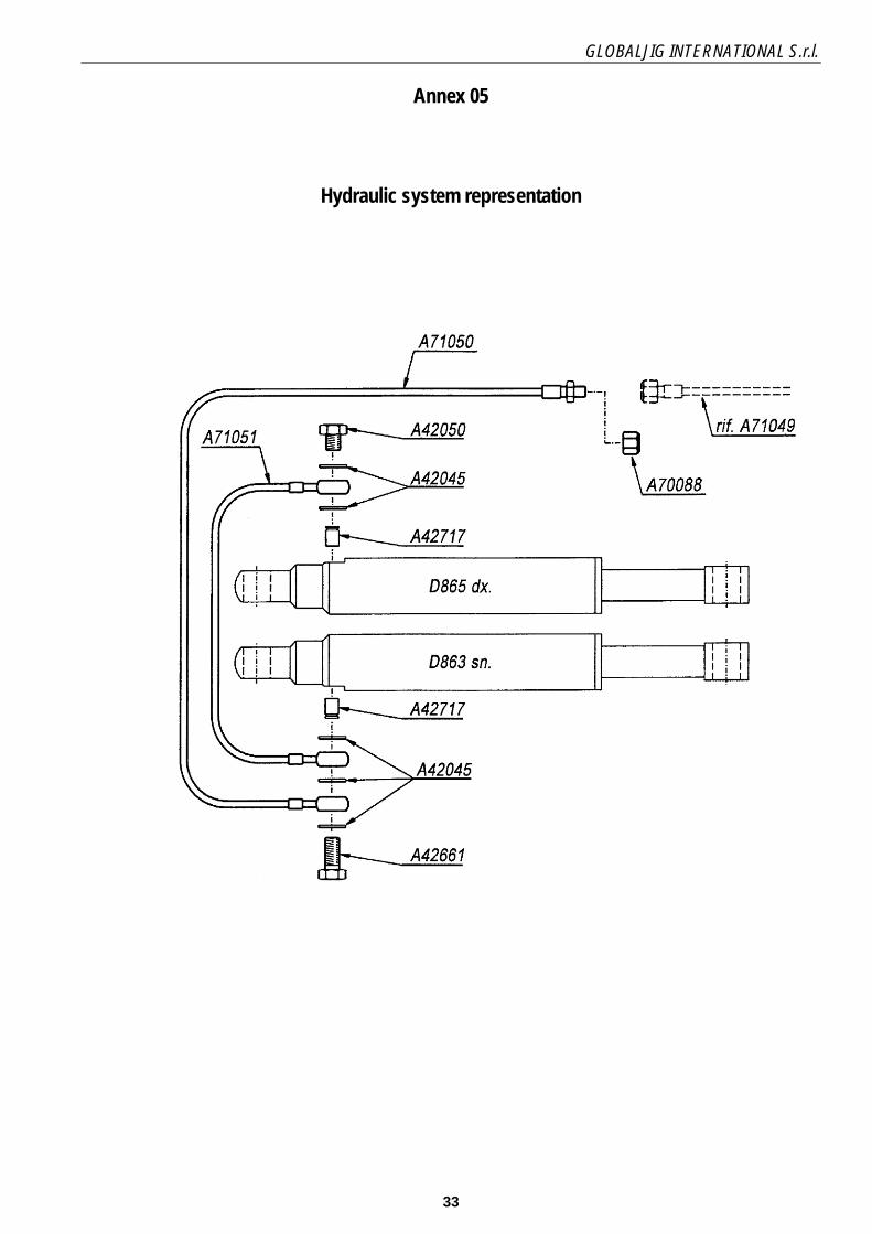
Annex 05
Hydraulic system representation
GLOBALJIG INTERNATIONAL S.r.l.
34
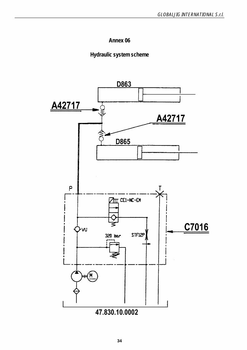
Annex 06
Hydraulic system scheme
GLOBALJIG INTERNATIONAL S.r.l.
35
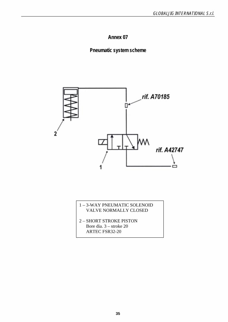
Annex 07
Pneumatic system scheme
1 – 3-WAY PNEUMATIC SOLENOID VALVE NORMALLY CLOSED 2 – SHORT STROKE PISTON Bore dia. 3 – stroke 20 ARTEC FSR32-20

GLOBALJIG INTERNATIONAL S.r.l.
36

GLOBALJIG INTERNATIONAL S.r.l.
37

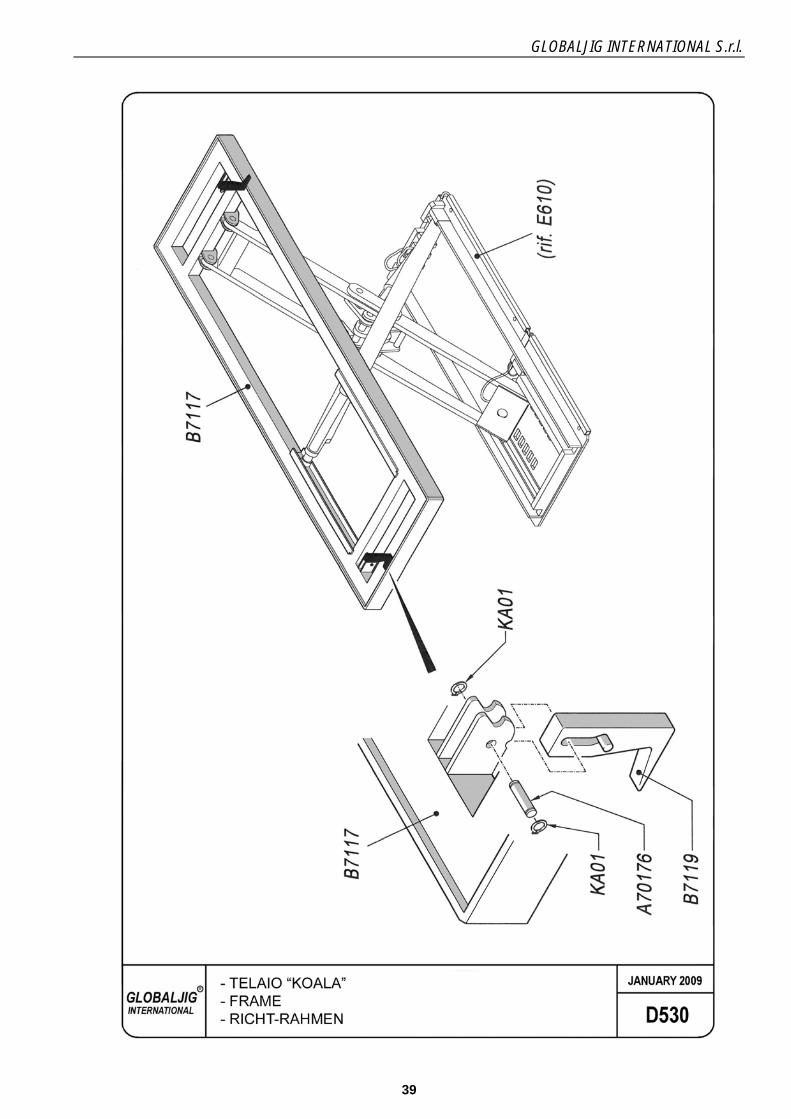
GLOBALJIG INTERNATIONAL S.r.l.
38
Leve
l and
“sm
ooth
” th
e su
ppor
t sur
face
fo
r anc
horin
g th
e ba
se o
f the
lift
App
rox.
200
CO
NTR
OL
UN
IT
Pos.
A
CO
NTR
OL
UN
IT
Pos.
B
Con
cret
e flo
orin
g R
CK
250
Th
ickn
ess
= m
in 1
8 cm
.
Mea
s. in
cm
.
Approx. 220 Min
. 6
tube
Lodg
ing
for t
he
"KO
ALA
” Pl
atfo
rm
Lift
FRONT OF THE PLATFORM
GLOBALJIG INTERNATIONAL S.r.l.
39

GLOBALJIG INTERNATIONAL S.r.l.
40
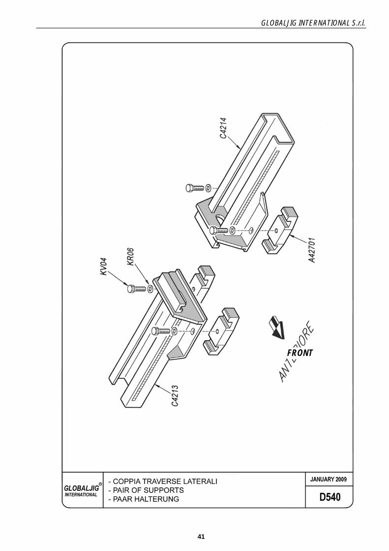
GLOBALJIG INTERNATIONAL S.r.l.
41
FRONT

GLOBALJIG INTERNATIONAL S.r.l.
42

GLOBALJIG INTERNATIONAL S.r.l.
43
TE UNI 5739 Screw TE UNI 5737 Screw Pin Clamp shoe Clamp flange
POS QTY NAME DIMENSIONS DRAWING / STANDARD MATERIAL WEIGHT (Kg)
NAME: Clamp flange and shoe unit
Iss./ Rev. Date Modifications Drawn up Checked Approved DRAWING No.
SCALE: - FORMAT: A4 SHEET - OF -

GLOBALJIG INTERNATIONAL S.r.l.
44
Complete support POS QTY NAME DIMENSIONS DRAWING / STANDARD MATERIAL WEIGHT (Kg)
NAME: COMPLETE SUPPORTS
Iss./ Rev. Date Modifications Drawn up Checked Approved DRAWING No.
SCALE: - FORMAT: A4 SHEET - OF -

GLOBALJIG INTERNATIONAL S.r.l.
45
Pad
POS QTY NAME DIMENSIONS DRAWING / STANDARD MATERIAL WEIGHT (Kg) NAME: SUPPORT WITH PAD
Iss./ Rev. Date Modifications Drawn up Checked Approved DRAWING No.
SCALE: - FORMAT: A4 SHEET - OF -
Support
Pad holder
GLOBALJIG INTERNATIONAL S.r.l.
46
GLOBALJIG INTERNATIONAL S.r.l.
47
NAME: TOWING ARM
Iss./ Rev. Date / Modifications Drawn up Checked Approved DRAWING No.
SCALE: - FORMAT: A3 SHEET - OF -
GLOBALJIG INTERNATIONAL S.r.l.
48

GLOBALJIG INTERNATIONAL S.r.l.
49

GLOBALJIG INTERNATIONAL S.r.l.
50

GLOBALJIG INTERNATIONAL S.r.l.
51
Annex 08
Hydraulic control unit
1 MANIFOLD 1
2 CAP 1
3 O-RING 1
4 VALVE 1
5 VALVE 1
6 VALVE 1
7 COUPLING 1
8 PUMP 1
9 SUCTION TUBE 1
10 DISCHARGE TUBE 2
11 CAP 1
12 CHOKE 1
13 SPECIAL NUT 4
14 FILTER 1
15 TANK 1
16 COIL 1
17 COLLAR 1
18 CAP 1
19 FILTER 1
20 CONNECTOR 1
GLOBALJIG INTERNATIONAL S.r.l.
52
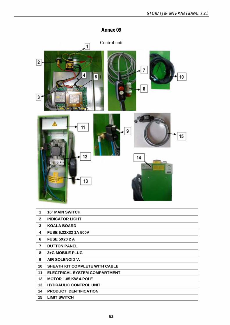
Annex 09
Control unit
1 16° MAIN SWITCH
2 INDICATOR LIGHT
3 KOALA BOARD
4 FUSE 6.32X32 1A 500V
6 FUSE 5X20 2 A
7 BUTTON PANEL
8 3+G MOBILE PLUG
9 AIR SOLENOID V.
10 SHEATH KIT COMPLETE WITH CABLE
11 ELECTRICAL SYSTEM COMPARTMENT
12 MOTOR 1.85 KW 4-POLE
13 HYDRAULIC CONTROL UNIT
14 PRODUCT IDENTIFICATION
15 LIMIT SWITCH

GLOBALJIG INTERNATIONAL S.r.l.
53
11. MACHINE LOG BOOK
Use the following form to make a note of the maintenance and any operations performed on the equipment. This will provide the user with the most appropriate information on the active cycle of the unit at all times.
Serial number
....................................
Date of initial operation
.................................................................... Page 1/2
DATE Repair or programmed maintenance Spare parts Signature and/or
stamp of the operator

GLOBALJIG INTERNATIONAL S.r.l.
54
Serial number
....................................
Date of initial operation
.................................................................... Page 2/2
DATE Repair or programmed maintenance Spare parts Signature and/or
stamp of the operator

GLOBALJIG INTERNATIONAL S.r.l.
55