Global Supplier of Stainless Steel, Fluid Handling ...
29
Global Supplier of Stainless Steel, Fluid Handling Packages and Components that Minimize Dirt in Paint Utilizing: PRODUCT CATALOG • Smooth bore designs • Cavity free features • Certified silicone and contaminant free systems
Transcript of Global Supplier of Stainless Steel, Fluid Handling ...

1
Global Supplier of Stainless Steel, Fluid Handling Packages and Components that Minimize
Dirt in Paint Utilizing:
P R O D U C T C A T A L O G
• Smooth bore designs• Cavity free features• Certified silicone and
contaminant free systems

2 3
From the most sophisticated painting operation to the most basic paint spray set up, our customers spend significant amounts time and money for filtration: Air supply, parts washers, paint pumping systems, robots, coating machines, spray applicators, even skilled personnel to operate the processes and equipment. Yet many paint shop managers still spend several hours a day battling with “dirt in paint”. So, what is it? Where does it come from? And why is it there?
In many cases, some part of these problems were initiated when the paint delivery or circulation system was first installed. Poor choices were made in the selection of devices used in the piping system- ball valves, fittings and connectors, flow control devices, hose connectors and hose or tubing to name a few. The key features essential in these components are smooth bore, cavity free, low shear and silicone or contaminant free.
Modern coating materials including resins, binders, effects pigments and fillers can “pack out” or settle in cracks, thread pockets and crevices. These agglomerations grow and eventually break free of their attachment point or cavity area, creating an expensive paint repair. Over the life of a system, this will generate increasing numbers of defects, and degrade the color and appearance finished products. It is necessary to specify and control the installation of equipment into the paint delivery or circulation system, focusing on meeting the smooth bore, cavity free, low shear and silicone or contaminant free component requirements as expansions, alterations or repairs are done to the piping or delivery system.
Let’s consider a simple and real-world example: If one spray defect is created per hour in a Paint Circulation System in a mid-size automobile paint shop that operates 2 shifts per day, there are 16 repairs done per day, an automotive body panel repair or reprocess is estimated at approximately $200 each, so $3200 per day is generated in repair
Table of Contents
1
24
3 56 13
127
11
8
9
10
14
1
24
6 1953
7
89
10
11
12
13
14
15
1617
18
20
Typical Manual Spray StationTypical Automated Spray Station
Paint Return
SprayBoothWall
Paint Supply
IsolationValve
IsolationValves
PressureGauge
BoothInterior
BoothInterior
BoothExterior
Paint Return
SprayBoothWall
Paint Supply
To Applicator
ColorValve
FluidBulkhead
PaintHosing
BoothInterior
BoothInterior
BoothExterior
1
24
3 56 13
127
11
8
9
10
14
1
24
6 1953
7
89
10
11
12
13
14
15
1617
18
20
Typical Manual Spray StationTypical Automated Spray Station
Paint Return
SprayBoothWall
Paint Supply
IsolationValve
IsolationValves
PressureGauge
BoothInterior
BoothInterior
BoothExterior
Paint Return
SprayBoothWall
Paint Supply
To Applicator
ColorValve
FluidBulkhead
PaintHosing
BoothInterior
BoothInterior
BoothExterior
As you can see there are a total of 7,352 connection points in the drop stations plus an estimated 1,800 in the paint mix room and piping racks. This is an illustration of the thousands of places that can generate “dirt in paint” from the paint delivery or paint circulation system in a mid sized Automotive Paint Shop. Hosco strongly encourages our customers to adopt controls on the components to be used in the paint delivery or circulation system and mandating Smooth Bore, Cavity Free, Low Shear, and Certified Silicone and Contaminant Free components only! This mandate includes Ball Valves, Fittings, Tees and Adapters, Flow Control devices, Pressure Regulation, Hose Connectors and Hose or Tubing components.
Typical Manual Spray StationManual stations total drop connection detail:
# of Colors # of Stations # of Drops
6 Prime 2 12 Prime
12 B/C 6 72 B/C
4 C/C 6 24 C/C
22 Materials 14 108 Total
108 drops x 14 Connection points/drop = 1,512 total connections!
Typical Automated Spray StationAutomated stations total drop connection detail:
# of Colors # of Stations # of Drops
6 Prime 2 36 Prime
12 B/C 16 192 B/C
4 C/C 16 64 C/C
22 Materials 38 292 Total
292 drops x 20 Connection points/drop = 5,840 total connections!
Table of Contents
5 Fluid Quick Disconnects
6 Mini-Filter, Tank Strainers
7 Applicator Flow Restrictors
8 Tube Assemblies, Strain Reliefs
9 Stainless Steel Hose
Connectors
13 Non-Conductive Nylon Hose
Connectors
14 Monoline Coaxial Hose
Assemblies
15 Nylon Hose and Tubing
16 Coaxial Paint Hose
17 Static Wire Air Hose,
Accessories
18 Fluoropolymer Tubing,
FEP/PTFE/PFA/FLM
20 Stainless Steel Jacketed Hose/
Fire Hyde
21 SSBV and HBV Ball Valves
25 H-Valves and 3 Way Ball Valves
26 HRS Manifold Paint Stations
28 Live Swivels and Check Valves
29 Circulation Adapters
30 SST Fittings and Adapters
36 SST Tees and Gauges
37 Compression Fittings -
Fractional Inch
40 Compression Fittings -
Metric
44 PreFis Connection Systems
47 Bundled Tubing and Hose
Management
49 Maintenance Tools
50 Shroud Cleaner Upgrades
54 Imagineering
55 Global Reach
55 Common Paint Systems
Connection Description
Where does Hosco fit into this initiative?The most important consideration is that 80% of the fluid connections in a paint delivery or paint circulation system are in the paint station drops that feed the paint application equipment, and this is the place to focus on for improving quality and throughput of the paint operation. Without the emphasis on smooth bore, cavity free, low shear and silicone or contaminant free requirements, automatic or manual paint station drops are the main source where dirt pockets can be found. A typical manual or automatic paint drop station is shown here to illustrate the thousands of places in a typical paint delivery system where paint can settle out and create “dirt in paint”. Using Hosco smooth bore, cavity free, low shear, and silicone and contaminant free certified components, available in both inch and metric sizes for operations around the world will insure optimal results, delivering clean paint to an efficient operation.
expense related to dirt in paint from the paint circulation system, over 250 days that adds up to $800,000/year! This is a tremendous justification for setting up and enforcing specific performance requirements for components to be used in the paint delivery or paint circulation system for all customers.
We strongly encourage all of our customers to insist on having control of the components to be used in the construction, alteration, expansion or repair of the piping and hosing of the paint delivery or circulation system in their plants!
Every paint shop organization has a common enemy…DIRT IN PAINT!
3

4 5All images are shown at approximately 1/2 scale unless otherwise noted.
CERTIFIED SILICONE FREE
Part Number T
SSQD-4 1/4 NPS
SSQD-4B 1/4 BSP
SSQD-6 3/8 NPS
SSQD-6B 3/8 BSP
Part Number T
SSQD-2T 1/8 NPT
SSQD-4T 1/4 NPT
SSQD-6T 3/8 NPT
Part Number T
SS-STEM-4 1/4 NPS
SS-STEM-4B 1/4 BSP
SS-STEM-6 3/8 NPS
SS-STEM-6B 3/8 BSP
Part Number T
SS-STEM-6CV 3/8 NPS
SS-STEM-6CVB 3/8 BSP
Part Number T
CSD-6 3/8 NPS
CSD-6B 3/8 BSP
Part Number Description
QDRK-6 Kit consists of 2 seats, 1 ball, and 1 spring
QDSK-6 Kit consists of 2 seats.
ToolsDummy Stem to hang QD Bodies and Hoses from.
Spare PartsWe offer 2 different kits with replacement parts.
QD Bodies Male Straight
Male Tapered
Stems Open Flow Female Straight
Checked Flow Female Straight
T
Top Seat PA
Bottom Seat PA
Ball SS
Spring SS
T
T
T
T
QUICK DISCONNECTS
Flow Control RestrictorsHosco flow control restrictors are available in stainless steel or lightweight composite materials. They are compact, low cost, lightweight, tamper proof, replace gun regulators, and have a smooth flow .350 I. D. recirculating passage with no pressure loss.
“Low Shear” Cavity Free Connection FittingsAll Hosco connection fittings feature its new “Low Shear” design that incorporates a taper-to-taper connection, which eliminates the blunt end or shelf surface found in conventional fittings. The design enhances Hosco’s smooth bore, cavity free product line helping metallic paint finishes retain their color, luster and quality while reducing system pressure loss, speeding installation procedures and furthering overall safety.
Quick Disconnect “No-Spit” Fittings Hosco paint quick disconnects work precisely with Hosco stems to eliminate the accumulation of paint and sludge that forms during everyday use of paint quick disconnects sets. The fittings eliminate the need for frequent solvent flushing or washing, cleaning away accumulated waste to prevent paint pits.
Restrictor/RegulatorThe Hosco HHR-6 restrictor/regulator incorporates a restrictor on a regulated paint outlet and then permits adjusting it to the desired flow rate to the spray gun. This helps attain maximum accuracy and repeatability while maintaining spray gun control even in the extremely low range. This restrictor/regulator is well suited for painting large structures with their inherent elevation changes from top to bottom such as aircraft, trucks and buses or for electrostatic air spray/HVLP painting applications.
FLUID FLOW IN
FLUID FLOW RETURN
.059 ORIFICE SELF PURGING
.350 PASSAGE
Hosco paint quick disconnects provide quick and easy color or material changing to the applicator in a paint or adhesive dispensing or spraying operation. The QD/Stem set minimizes the need for frequent solvent flushing or washing to clean away accumulated waste and to prevent paint spits that can cause defects in the product surface being sprayed. Hosco SSQD and SS-Stem combinations are the most used SST set throughout the world!
Feature and Benefits304/316 SST Construction • Compatible with all coatings
and adhesive materials known• SST construction provides long
service life• Rebuildable with repair kits
300 PSI Working Pressure • Compatible with a wide range
of applicators and application pressure
Precision Design/No Spit Operation• Eliminates coating build up in
the QD seal area• Reduces cleaning intervals• Rebuildable with spare parts kits
Unique Manufacturing Processes• MIM molded stem reduces size
and weight, Bayonet QD body is the most compact in the world
• Large flow passageways minimize shear and coating degradation and subsequent pressure or flowrate losses
Encapsulated Ball Valves All Hosco 316 series patented encapsulated ball valves have no cavities around the ball so there is no place for paint to collect and dry. They also include PTFE seats and an adjustable retainer ring. All ball valves are rated for 1000 PSI (70 BAR) working pressure.
Hosco’s Technology and Performance Promise:
Our smooth bore, cavity free, low shear and silicone and contaminant free focus and promise will pave the way for dirt free paint delivery to the spray applicators.
Here are five product area examples:

6 7All images are shown at approximately 1/2 scale unless otherwise noted.All images are shown at approximately 1/2 scale unless otherwise noted.
CERTIFIED SILICONE FREE CERTIFIED SILICONE FREE
Hosco Mini-Filters and Station Filters incorporate SST wire mesh filter elements to provide absolute filtration at the specified wire mesh or micron size. There are 7 mesh or micron sizes available in the Mini-Filter products and 2 sizes available in the Station filter. The finest mesh size is 500 mesh or 25 micron and the coarsest mesh size is 40 mesh or 350 micron. In general, solvents and clear fluids would use the finer mesh and the solid color paints, metallic paints or highly filled or high solids paints will use the coarser mesh elements. The Mini-Filters have a compact design, and can be installed in line to eliminate “dirt in paint”. The Station Filter is a good solution to providing filtration in a Pressure Pot or 5-gallon pail pumping set up and some unique “in-line” filtration in larger fluid piping systems.
Feature and BenefitsSST Construction Throughout• Materials compatible with all
coatings or adhesives• Long life
Low Shear Design • Large flow passageways
minimize shear and coating degradation and subsequent pressure or flowrate losses
Cavity Free & Smooth Bore Design• To minimize material pack out or
“dirt in paint” and provide easy to clean and flush components
2500 Psi Working Pressure*• Compatible with a wide range
of applicators and application pressure
Compact Design• Mini-filter allows spray operators
to maneuver the spray gun into small areas or tight spaces much easier than alternatives
Mini-Filter Assembly Female Straight x Male Straight
MINI-FILTER AND TANK STRAINER FILTER
Part Number T (F) T1 (M) SIZE
MF-6-40 3/8 NPS 3/8 NPS 40 MESH/350 MICRON
MF-6B-40B 3/8 BSP 3/8 BSP 40 MESH/350 MICRON
MF-6-70 3/8 NPS 3/8 NPS 70 MESH/200 MICRON
MF-6B-70B 3/8 BSP 3/8 BSP 70 MESH/200 MICRON
MF-6-100 3/8 NPS 3/8 NPS 100 MESH/149 MICRON
MF-6B-100B 3/8 BSP 3/8 BSP 100 MESH/149 MICRON
MF-6-150 3/8 NPS 3/8 NPS 150MESH/100 MICRON
MF-6B-150B 3/8 BSP 3/8 BSP 150MESH/100 MICRON
MF-6-200 3/8 NPS 3/8 NPS 200 MESH/74 MICRON
MF-6B-200B 3/8 BSP 3/8 BSP 200 MESH/74 MICRON
MF-6-325 3/8 NPS 3/8 NPS 325 MESH/44 MIRCON
MF-6B-325B 3/8 BSP 3/8 BSP 325 MESH/44 MIRCON
MF-6-500 3/8 NPS 3/8 NPS 500 MESH/25 MICRON
MF-6B-500B 3/8 BSP 3/8 BSP 500 MESH/25 MICRON
Filter Cartridge Only
Part Number SIZE
MFC-40 40 MESH/350 MICRON
MFC-70 70 MESH/200 MICRON
MFC-100 100 MESH/149 MICRON
MFC-150 150MESH/100 MICRON
MFC-200 200 MESH/74 MICRON
MFC-325 325 MESH/44 MIRCON
MFC-500 500 MESH/25 MICRON
Mini-Filter Body Only Female Straight x Male Straight
Part Number T (F) T1 (M)
MFB 3/8 NPS 3/8 NPS
MFB-B 3/8 BSP 3/8 BSP
T
T1
Filter CartridgeBody
Tank Strainer Filter Female Straight x Male Straight
Part Number T (F) T1 (M) SIZE
TSF-6-100 3/8 NPS 3/8 NPS 100 MESH
TSF-6-60 3/8 NPS 3/8 NPS 60 MESH
Assembly
Part Number T (F) T1 (M) SIZE
TSF-6-100-BRKT 3/8 NPS 3/8 NPS 100 MESH
TSF-6-60-BRKT 3/8 NPS 3/8 NPS 60 MESH
Assembly with Bracket
Part Number SIZE
TSF-100 100 MESH
TSF-100-10PK 100 MESH
TSF-60 60 MESH
TSF-60-10PK 60 MESH
Filter Cartridge
Part Number
TSF-BRKT
Bracket
Assembly Assembly with Bracket
Filter Cartridge Only
Bracket Only
T
T1
Images are approx. 1/3 scale
Note: We recommend users consult their material suppliers for proper selection of filtration size.
Images are approx. 2/3 scale
Hosco Stainless Steel Restrictors provide reliable, long life fluid flow control to an applicator. The family of products consists of recirculating and non-circulating versions that can be internally set (tamperproof) or externally adjusted even while dispensing. The long tapered needle design of the restrictors provide fine flowrate adjustments from complete shut off to over 1000 cc/min (depending on pressure and viscosity). Settings are repeatable from restrictor to restrictor station so set up is relatively easy. The internally set styles may require the RAB-6 Tool to provide initial set point adjustment while the restrictor is “on line”. The externally adjusted versions require an Allen wrench for adjustment which is included with the restrictor.
Feature and BenefitsSST Construction• Long life• Compatible with all coatings and
adhesive materials known
Compact Design• Allows spray operators to
maneuver the spray gun into small areas or tight spaces much easier than alternatives
• Much smaller and lighter than regulator based alternatives
Multiple Configurations• Tamperproof or externally
adjustable versions• Circulating or non-circulating
versions• In-line or 45 degree hose
connection versions on circulating versions to keep hoses away from the product being coated
Low Shear Design• 0.350” smooth bore
passageways in circulating versions protect the coating from excessive shear during operation and minimize pressure loss of the recirculating function
Highest ROI Flow Control Device• Hosco Restrictors are generally
1/3 the cost of older regulator versions, and last easily 10X longer between service events or replacement
RESTRICTORS
Externally Adjustable Female Straight x Male Straight
Tool for Internally Adjustable Restrictor Adjusting Block Female Straight x Male Straight
Part Number T(F) T1(M)
RAB-6 3/8 NPS 3/8 NPS
RAB-6B 3/8 BSP 3/8 BSP
T
T1T1
T
T1
T
T1
T
T1
T1
RY
RIL
HRU
RIA
RYA
Part Number T(F) T1(M)
RIA-6 3/8 NPS 3/8 NPS
RIA-6B 3/8 BSP 3/8 BSP
Part Number T(F) T1(M)
RYA-6 3/8 NPS 3/8 NPS
RYA-6B 3/8 BSP 3/8 BSP
RYA-4 3/8 NPS 1/4 NPS
RYA-4B 3/8 BSP 1/4 BSP
Internally Adjustable Female Straight x Male Straight
Part Number T(F) T1(M)
RY-4 3/8 NPS 1/4 NPS
RY-4B 3/8 BSP 1/4 BSP
RY-6 3/8 NPS 3/8 NPS
RY-6B 3/8 BSP 3/8 BSP
Part Number T(F) T1(M)
RIL-6 3/8 NPS 3/8 NPS
RIL-6B 3/8 BSP 3/8 BSP
Part Number T(F) T1(M)
RIL-2T 3/8 NPS 1/8 NPT
Female Straight x Male Tapered
Part Number T(F) T1(M)
HRU-6 3/8 NPS 3/8 NPS
HRU-6B 3/8 BSP 3/8 BSP
T1
T
T1 T1
T

8 9All images are shown at approximately 1/2 scale unless otherwise noted.All images are shown at approximately 1/2 scale unless otherwise noted.
CERTIFIED SILICONE FREE CERTIFIED SILICONE FREE
Hosco tube assemblies are designed to provide strain relief and routing control. In addition, the smooth radius sweeps eliminate coating damage and shear, while controlling restriction to keep piping systems in balance. These tube assemblies are typically constructed of 316 SST seamless tubing in 1/4”, 5/16”, and 3/8” OD tube sizes, and are also available in metric sizes 8mm to 18mm. The tube assemblies are provided typically with 1/4” and 3/8” male or female swivel nut connection points in NPS or BSPP (PF), but also can be provided in JIC, compression, NPT or BSPT (PT), or open tube stub configurations.
Feature and BenefitsMultiple Configurations• In-line, 45, 60 or 90 degree inlet
/outlet(s) versions• 1/4”, 5/16”, 3/8”, plus multiple
metric OD tube sizes available• NPT/BSPT(PT), NPS/BSPP(PF),
Compression, JIC, and Tube Stub connection points
SST Construction• 304L/316 materials compatible
with all coatings or adhesives• Long life
Unique Manufacturing Processes• Unique processing provides
chemical free passivation and absolutely clean product for installation
• Nickel braze process assures full 316 SST construction and absolute compatibility to even De-Ionized water systems
Cavity Free & Smooth Bore Design• To minimize material pack out or
“dirt in paint” and provide easy to clean and flush components
Low Shear Design • Large flow passageways
minimize shear and coating degradation and subsequent pressure or flowrate losses
TUBE ASSEMBLIES
Male Straight x Female Straight x 3-3/4” long
TT1
Part Number T(M) T1(F)
GE-600 3/8 NPS 3/8 NPS
GE-600B 3/8 BSP 3/8 BSP
Male Straight x Female Straight 90°
T
T1
Part Number T(M) T1(F)
SSL4-4SN-90 1/4 NPS 1/4 NPS
SSL6-4SN-90 3/8 NPS 1/4 NPS
SSL6-6SN-90 3/8 NPS 3/8 NPS
SSL6B-6SNB-90 3/8 BSP 3/8 BSP
Female Straight x Female Straight 90°
T
T1
Part Number T(F) T1(F)
SSL6SN-4SN-90 3/8 NPS 1/4 NPS
SSL6SN-6SN-90 3/8 NPS 3/8 NPS
SSL6SNB-6SNB-90 3/8 BSP 3/8 BSP
SSL4SN-4SN-90 1/4 NPS 1/4 NPS
Female Straight x Hose Connection Part Number T(F) T1(F)
SSL-6SN-6X8-SG 3/8 NPS 6MMX8MM
SSL-6SN-7X9.6-SG 3/8 NPS 7MMX9.6MM
SSL-6SN-7X10-SG 3/8 NPS 7MMX10MM
SSL-6SN-9X12-SG 3/8 NPS 9MMX12MM
T
T1
Part Number T(M) T1(F)
GE-630 3/8 NPS 3/8 NPS
GE-630B 3/8 BSP 3/8 BSP
Male Straight x Female Straight 30° x 3-3/4”
T
T1
SST HOSE FITTINGS
No Springguard With Springguard No Springguard With Springguard
Hose Connector Size
OD ID Part No.
1/4” NPS(F) 3/8”NPS(F) 1/4” NPS(F) 3/8”NPS(F) 1/4” NPS(F) 3/8”NPS(F) 1/4” NPS(F) 3/8”NPS(F)
BSP(F) Add “-B” Suffix to P/N (Example 1438-SG-B)
3/16” (4.8MM) .138” (3.5MM) NHA-0302 1814-SS-187 1838-SS-187 1814-SG-187 1838-SG-287 1814-SS-90-187 1838-SS-90-187 1814-SG-90-187 1838-SG-90-187
1/4” (6.35MM) .180” (4.6MM) NHA-0403 31614-SS-256 31638-SS-256 31614-SG-256 31638-SG-256 31614-SS-90-256 31638-SS-90-256 31614-SG-90-256 31638-SG-90-256
1/4” (6.35MM) .170” (4.31MM) NHA-250170 17014-SS-256 17038-SS-256 17014-SG-256 17038-SG-256 17014-SS-90-256 17038-SS-90-256 17014-SG-90-256 17038-SG-90-256
5/16” (8MM) .236” (6MM) NHA-0504 NHA-8X6
6X8-14-SS 6X8-38-SS 6X8-14-SG 6X8-38-SG 6X8-14-SS-90 6X8-38-SS-90 6X8-14-SG-90 6X8-38-SG-90
3/8” (9.6MM) .275” (7MM) NHA-375275 0714-SS 0738-SS 0714-SG 0738-SG 0714-SS-90 0738-SS-90 0714-SG-90 0738-SG-90
1/2” (12.7MM) 3/8” (9.5MM) NHA-0806 3814-SS 3838-SS 3814-SG 3838-SG 3814-SS-90 3838-SS-90 3814-SG-90 3838-SG-90
.236” (6MM) .157” (4MM) NHA-6X4 4X6-14-SS 4X6-38-SS 4X6-14-SG 4X6-38-SG 4X6-14-SS-90 4X6-38-SS-90 4X6-14-SG-90 4X6-38-SG-90
.354” (9MM) .236” (6MM) NHA-9X6 6X9-14-SS 6X9-38-SS 6X9-14-SG 6X9-38-SG 6X9-14-SS-90 6X9-38-SS-90 6X9-14-SG-90 6X9-38-SG-90
.394” (10MM) .275” (7MM) NHA-10X7 7X10-14-SS 7X10-38-SS 7X10-14-SG 7X10-38-SG 7X10-14-SS-90 7X10-38-SS-90 7X10-14-SG-90 7X10-38-SG-90
.394” (10MM) 5/16” (8MM) NHA-10X8 8X10-14-SS 8X10-38-SS 8X10-14-SG 8X10-38-SG 8X10-14-SS-90 8X10-38-SS-90 8X10-14-SG-90 8X10-38-SG-90
.472” (12MM) .354” (9MM) NHA-12X9 9X12-14-SS 9X12-38-SS 9X12-14-SG 9X12-38-SG 9X12-14-SS-90 9X12-38-SS-90 9X12-14-SG-90 9X12-38-SG-90
.472” (12MM) .394” (10MM) NHA-12X10 10X12-14-SS 10X12-38-SS 10X12-14-SG 10X12-38-SG 10X12-14-SS-90 10X12-38-SS-90 10X12-14-SG-90 10X12-38-SG-90
Nylon Tubing
Hosco SST Hose Connectors are designed to provide connections of hose and tubing using the robust and industry leading Hosco barb and nut style retention system.
These connectors significantly exceed the performance of other style connectors and provide the highest level of safe and reliable connections found today for use in flammable or hazardous fluid handling.
The SST connectors are available in both spring-guard versions to provide support for the hose or tube at the connector when strain relief is needed, or non-springguard version for a static or stationary connection point.
The SST family of hose connectors are available in common sizes of fractional inch or metric hose connection ends, and in straight or compact 90 degree configurations. The connection point is available in two common ends- NPT/BSPT(PT) male in 1/8”, 1/4”, and 3/8” sizes, or NPS/BSPP(PF) female swivel nut in 1/4” and 3/8” sizes.
Feature and BenefitsSST Materials of Construction• Suitable for most paints, coatings or solvents in use• Wide range of chemical compatibility• Reusable, and long service life
Multiple Sizes, Two Configurations• Provides one common style of connector for fractional
inch and metric hoses or tubes with straight or 90 degree styles
Robust Designs• Mechanical retention of hose or tube is best available
technology to insure safety and trouble free operation• NPS/BSPP(PF) connector design is intended for multiple
or frequent “make & break” connections for servicing or replacement of components
Patented Technology• Connectors can be installed with the lowest wrench
forces in the industry, which is important as dispense or paint stations are made more compact and recessed minimizing installers ability to exert high wrench forces.

10 11All images are shown at approximately 1/2 scale unless otherwise noted.All images are shown at approximately 1/2 scale unless otherwise noted.
CERTIFIED SILICONE FREE CERTIFIED SILICONE FREE
SST HOSE FITTINGS CONTINUED
No Springguard With Springguard No Springguard With Springguard
Hose Connector Size
OD ID Part No.
1/4” NPS(F) 3/8”NPS(F) 1/4” NPS(F) 3/8”NPS(F) 1/4” NPS(F) 3/8”NPS(F) 1/4” NPS(F) 3/8”NPS(F)
BSP(F) Add “-B” Suffix to P/N (Example 1438-SG-B)
.225” (5.7MM) 1/8” (3.2MM) NP-2 1814-SS 1838-SS 1814-SG 1838-SG 1814-SS-90 1838-SS-90 1814-SG-90 1838-SG-90
.264” (6.7MM) 3/16” (4.8MM) NP-3 31614-SS 31638-SS 31614-SG 31638-SG 31614-SS-90 31638-SS-90 31614-SG-90 31638-SG-90
.350” (8.9MM) 1/4” (6.35MM) NP-4 1414-SS 1438-SS 1414-SG 1438-SG 1414-SS-90 1438-SS-90 1414-SG-90 1438-SG-90
.350” (8.9MM) 1/4” (6.35MM) NP-4TL 1414-SS 1438-SS 1414-SG 1438-SG 1414-SS-90 1438-SS-90 1414-SG-90 1438-SG-90
.425”(10.8MM) 3/16” (8MM) NP-5 51614-SS 51638-SS 51614-SG 51638-SG 51614-SS-90 51638-SS-90 51614-SG-90 51638-SG-90
.500”(12.7MM) 3/8” (9.5MM) NP-6 3814-SS 3838-SS 3814-SG 3838-SG 3814-SS-90 3838-SS-90 3814-SG-90 3838-SG-90
Nylon Hose
OD ID Part No.
1/4” NPS(F) 3/8”NPS(F) 1/4” NPS(F) 3/8”NPS(F) 1/4” NPS(F) 3/8”NPS(F) 1/4” NPS(F) 3/8”NPS(F)
BSP(F) Add “-B” Suffix to P/N (Example 1438-SG-B)
.350” (8.9MM) 1/4” (6.35MM) CPH-4 1414-SS 1438-SS 1414-SG 1438-SG 1414-SS-90 1438-SS-90 1414-SG-90 1438-SG-90
.350” (8.9MM) 1/4” (6.35MM) CPH-4TL 1414-SS 1438-SS 1414-SG 1438-SG 1414-SS-90 1438-SS-90 1414-SG-90 1438-SG-90
.425” (10.5MM) 5/16” (8MM) CPH-5 51614-SS 51638-SS 51614-SG 51638-SG 51614-SS-90 51638-SS-90 51614-SG-90 51638-SG-90
.500”(12.7MM) 3/8” (9.5MM) CPH-6 3814-SS 3838-SS 3814-SG 3838-SG 3814-SS-90 3838-SS-90 3814-SG-90 3838-SG-90
Coaxial Paint Hose
OD ID Part No.
1/4” NPS(F) 3/8”NPS(F) 1/4” NPS(F) 3/8”NPS(F) 1/4” NPS(F) 3/8”NPS(F) 1/4” NPS(F) 3/8”NPS(F)
BSP(F) Add “-B” Suffix to P/N (Example 1438-SG-T-B)
3/16” (4.76MM)
1/8” (3.18MM) FEP-0302 1814-SS-187 1838-SS-187 1814-SG-187 1838-SG-187 1814-SS-90-187 1838-SS-90-187 1814-SG-90-187 1838-SG-90-187
1/4” (6.35MM) 1/8” (3.18MM) FEP-0402 1814-SS-T 1838-SS-T 1814-SG-T 1838-SG-T 1814-SS-90-T 1838-SS-90-T 1814-SG-90-T 1838-SG-90-T
1/4” (6.35MM) .170” (4.31MM) FEP-250170 17014-SS-256 17038-SS-256 17014-SG-256 17038-SG-256 17014-SS-90-256 17038-SS-90-256 17014-SG-90-256 17038-SG-90-256
1/4” (6.35MM) 3/16” (4.76MM)
FEP-0403 31614-SS-256 31638-SS-256 31614-SG-256 31638-SG-256 31614-SS-90-256 31638-SS-90-256 31614-SG-90-256 31638-SG-90-256
5/16” (7.94MM)
3/16” (4.76MM)
FEP-0503 31614-SS-T 31638-SS-T 31614-SG-T 31638-SG-T 31614-SS-90-T 31638-SS-90-T 31614-SG-90-T 31638-SG-90-T
5/16” (7.94MM)
1/4” (6.35MM) FEP-0504 1414-SS-312 1438-SS-312 1414-SG-312 1438-SG-312 1414-SS-90-312 1438-SS-90-312 1414-SG-90-312 1438-SG-90-312
3/8” (9.53MM) 1/4” (6.35MM) FEP-0604 1414-SS-T 1438-SS-T 1414-SG-T 1438-SG-T 1414-SS-90-T 1438-SS-90-T 1414-SG-90-T 1438-SG-90-T
1/2” (12.7MM) 3/8” (9.53MM) FEP-0806 3814-SS-T 3838-SS-T 3814-SG-T 3838-SG-T 3814-SS-90-T 3838-SS-90-T 3814-SG-90-T 3838-SG-90-T
.196” (5MM) .118” (3MM) FEPM-5X3 3X5-14-SS 3X5-38-SS 3X5-14-SG 3X5-38-SG 3X5-14-SS-90 3X5-38-SS-90 3X5-14-SG-90 3X5-38-SG-90
.236” (6MM) 5/32” (4MM) FEPM-6X4 4X6-14-SS 4X6-38-SS 4X6-14-SG 4X6-38-SG 4X6-14-SS-90 4X6-38-SS-90 4X6-14-SG-90 4X6-38-SG-90
5/16” (8MM) .236” (6MM) FEPM-8X6 6X8-14-SS 6X8-38-SS 6X8-14-SG 6X8-38-SG 6X8-14-SS-90 6X8-38-SS-90 6X8-14-SG-90 6X8-38-SG-90
.354” (9MM) .236” (6MM) FEPM-9X6 6X9-14-SS 6X9-38-SS 6X9-14-SG 6X9-38-SG 6X9-14-SS-90 6X9-38-SS-90 6X9-14-SG-90 6X9-38-SG-90
.394” (10MM) .275” (7MM) FEPM-10X7 7X10-14-SS 7X10-38-SS 7X10-14-SG 7X10-38-SG 7X10-14-SS-90 7X10-38-SS-90 7X10-14-SG-90 7X10-38-SG-90
.394” (10MM) 5/16” (8MM) FEPM-10X8 8X10-14-SS 8X10-38-SS 8X10-14-SG 8X10-38-SG 8X10-14-SS-90 8X10-38-SS-90 8X10-14-SG-90 8X10-38-SG-90
.472” (12MM) .354” (9MM) FEPM-12X9 9X12-14-SS 9X12-38-SS 9X12-14-SG 9X12-38-SG 9X12-14-SS-90 9X12-38-SS-90 9X12-14-SG-90 9X12-38-SG-90
.472” (12MM) .394” (10MM) FEPM-12X10 10X12-14-SS 10X12-38-SS 10X12-14-SG 10X12-38-SG 10X12-14-SS-90 10X12-38-SS-90 10X12-14-SG-90 10X12-38-SG-90
Fluoropolymer Tubing
OD ID Part No.
1/4” NPS(F) 3/8”NPS(F) 1/4” NPS(F) 3/8”NPS(F) 1/4” NPS(F) 3/8”NPS(F) 1/4” NPS(F) 3/8”NPS(F)
BSP(F) Add “-B” Suffix to P/N (Example 1438-SG-B)
5/8” (15.9MM) 5/16” (8MM) HOSCO X-1 HHC-4527 HHC-4547 N/A N/A N/A N/A N/A N/A
.47” (12MM) 5/16” (8MM) HOSCO X-2 X-2-14-SS X-2-38-SS X-2-14-SG X-2-38-SG N/A N/A N/A N/A
.47” (12MM) 5/16” (8MM) HOSCO X-4 CALL OR EMAIL FOR AVAILABLE HOSE ASSEMBLY OPTIONS
Static Wire Air Hose
SST HOSE FITTINGS - TAPERED AND SPARE PARTS
No Springguard Tapered With Springguard Tapered Springguard (Spare Part)
STP Nut (Spare Part)
Hose Connector Size For Each Hose Type and Size
OD ID Part No.
1/8” NPT(M) 1/4”NPT(M) 1/8” NPT(M) 1/4”NPT(M)
BSPT (M) Call or email for availability (Example 1818-BT-SS)
3/16” (4.8MM) .138” (3.5MM) NHA-0302 1818-T-SS-187 1814-T-SS-187 1818-T-SG-187 1814-T-SG-187 250SG 187STP
1/4” (6.35MM) .180” (4.6MM) NHA-0403 31618-T-SS-256 31614-T-SS-256 31618-T-SG-256 31614-T-SG-256 264SG 250STP-2
1/4” (6.35MM) .170” (4.31MM) NHA-250170 17018-T-SS-256 17014-T-SS-256 17018-T-SG-256 17014--T-SG-256 250SG 250STP
5/16” (8MM) .236” (6MM) NHA-0504 NHA-8X6
6X8-18-T-SS 6X8-14-T-SS 6X8-18-T-SG 6X8-14-T-SG 350SG 315STP
3/8” (9.6MM) .275” (7MM) NHA-375275 0718-T-SS 0714-T-SS 0718-T-SG 0714-T-SG 393SG 375STP
1/2” (12.7MM) 3/8” (9.5MM) NHA-0806 N/A 3814-T-SS N/A 3814-T-SG 500SG 500STP
.236” (6MM) .157” (4MM) NHA-6X4 4X6-18-T-SS 4X6-14-T-SS 4X6-18-T-SG 4X6-14-T-SG 250SG 236STP
.354” (9MM) .236” (6MM) NHA-9X6 6X9-18-T-SS 6X9-14-T-SS 6X9-18-T-SG 6X9-14-T-SG 350SG 350STP
.394” (10MM) .275” (7MM) NHA-10X7 7X10-18-T-SS 7X10-14-T-SS 7X10-18-T-SG 7X10-14-T-SG 350SG 350STP
.394” (10MM) 5/16” (8MM) NHA-10X8 8X10-18-T-SS 8X10-14-T-SS 8X10-18-T-SG 8X10-14-T-SG 437SG 393STP-2
.472” (12MM) .354” (9MM) NHA-12X9 9X12-18-T-SS 9X12-14-T-SS 9X12-18-T-SG 9X12-14-T-SG 500SG 472STP
.472” (12MM) .394” (10MM) NHA-12X10 N/A 10X12-14-T-SS N/A 10X12-14-T-SG 500SG 472STP
Nylon Tubing
OD ID Part No.
1/8” NPT(M) 1/4”NPT(M) 1/8” NPT(M) 1/4”NPT(M)
BSPT (M) Call or email for availability (Example 1818-BT-SS)
.225” (5.7MM) 1/8” (3.2MM) NP-2 1818-T-SS 1814-T-SS 1818-T-SG 1814-T-SG 250SG 225STP
.264” (6.7MM) 3/16” (4.8MM NP-3 31618-T-SS 31614-T-SS 31618-T-SG 31614-T-SG 264SG 264STP
.350” (8.9MM) 1/4” (6.35MM) NP-4 1418-T-SS 1414-T-SS 1418-T-SG 1414-T-SG 350SG 350STP
.350” (8.9MM) 1/4” (6.35MM) NP-4TL 1418-T-SS 1414-T-SS 1418-T-SG 1414-T-SG 350SG 350STP
.425” (10.8MM) 3/16” (8MM) NP-5 N/A 51614-T-SS N/A 51614-T-SG 437SG 437STP
.500” (12.7MM) 3/8” (9.5MM) NP-6 N/A 3814-T-SS N/A 3814-T-SG 500SG 500STP
Nylon Hose
OD ID Part No.
1/8” NPT(M) 1/4”NPT(M) 1/8” NPT(M) 1/4”NPT(M)
BSPT (M) Call or email for availability (Example 1818-BT-SS)
.350” (8.9MM) 1/4” (6.35MM) CPH-4 1418-T-SS 1414-T-SS 1418-T-SG 1414-T-SG 350SG 350STP
.350” (8.9MM) 1/4” (6.35MM) CPH-4TL 1418-T-SS 1414-T-SS 1418-T-SG 1414-T-SG 350SG 350STP
.425” (10.5MM) 5/16” (8MM) CPH-5 N/A 51614-T-SS N/A 51614-T-SG 437SG 437STP
.500” (12.7MM) 3/8” (9.5MM) CPH-6 N/A 3814-T-SS N/A 3814-T-SG 500SG 500STP
Coaxial Paint Hose
OD ID Part No.
1/8” NPT(M) 1/4”NPT(M) 1/8” NPT(M) 1/4”NPT(M)
BSPT (M) Call or email for availability (Example 1818-BT-SS)
.225” (5.7MM) 1/8” (3.2MM) NP-2 1818-T-SS 1814-T-SS 1818-T-SG 1814-T-SG 250SG 225STP
.264” (6.7MM) 3/16” (4.8MM NP-3 31618-T-SS 31614-T-SS 31618-T-SG 31614-T-SG 264SG 264STP
.350” (8.9MM) 1/4” (6.35MM) NP-4 1418-T-SS 1414-T-SS 1418-T-SG 1414-T-SG 350SG 350STP
.350” (8.9MM) 1/4” (6.35MM) NP-4TL 1418-T-SS 1414-T-SS 1418-T-SG 1414-T-SG 350SG 350STP
.425” (10.8MM) 3/16” (8MM) NP-5 N/A 51614-T-SS N/A 51614-T-SG 437SG 437STP
.500” (12.7MM) 3/8” (9.5MM) NP-6 N/A 3814-T-SS N/A 3814-T-SG 500SG 500STP
11All images are shown at approximately 1/2 scale unless otherwise noted.

12 13All images are shown at approximately 1/2 scale unless otherwise noted.All images are shown at approximately 1/2 scale unless otherwise noted.
CERTIFIED SILICONE FREE CERTIFIED SILICONE FREE
SST HOSE FITTINGS - TAPERED AND SPARE PARTS CONTINUED
No Springguard Tapered With Springguard Tapered Springguard (Spare Part)
STP Nut (Spare Part)
Hose Connector Size For Each Hose Type and Size
OD ID Part No.
1/8” NPT(M) 1/4”NPT(M) 1/8” NPT(M) 1/4”NPT(M)
BSPT (M) Call or email for availability (Example 1818-BT-SS)
3/16” (4.76MM)
1/8” (3.18MM) FEP-0302 1818-T-SS-187 1814-T-SS-187 1818-T-SG-187 1814-T-SG-187 250SG 187STP
1/4” (6.35MM) 1/8” (3.18MM) FEP-0402 1818-T-SS-T 1814-T-SS-T 1818-T-SG-T 1814-T-SG-T 250SG 250STP
1/4” (6.35MM) .170” (4.31MM) FEP-250170 17018-T-SS-256 17014-T-SS-256 17018-T-SG-256 17014-T-SG-256 250SG 250STP
1/4”(6.35MM) 3/16” (4.76MM)
FEP-0403 31618-T-SS-256 31614-T-SS-256 31618-T-SG-256 31614-T-SG-256 264SG 250STP-2
5/16” (7.94MM)
3/16” (4.76MM)
FEP-0503 31618-T-SS-T 31614-T-SS-T 31618-T-SG-T 31614-T-SG-T 312SG 312STP
5/16” (7.94MM)
1/4” (6.35MM) FEP-0504 1418-T-SS-312 1414-T-SS-312 1418-T-SG-312 1414-T-SG-312 350SG 315STP
3/8” (9.53MM) 1/4” (6.35MM) FEP-0604 1418-T-SS-T 1414-T-SS-T 1418-T-SG-T 1414-T-SG-T 393SG 375STP
1/2” (12.7MM) 3/8” (9.53MM) FEP-0806 N/A 3814-T-SS-T N/A 3814-T-SG-T 500SG 500STP
.196” (5MM) .118” (3MM) FEPM-5X3 N/A 3X5-14-T-SS N/A 3X5-14-T-SG 250SG 187STP
.236” (6MM) 5/32” (4MM) FEPM-6X4 4X6-18-T-SS 4X6-14-T-SS 4X6-18-T-SG 4X6-14-T-SG 250SG 236STP
5/16” (8MM) .236” (6MM) FEPM-8X6 6X8-18-T-SS 6X8-14-T-SS 6X8-18-T-SG 6X8-14-T-SG 350SG 315STP
.354” (9MM) .236” (6MM) FEPM-9X6 6X9-18-T-SS 6X9-14-T-SS 6X9-18-T-SG 6X9-14-T-SG 350SG 350STP
.394” (10MM) .275” (6MM) FEPM-10X7 7X10-18-T-SS 7X10-14-T-SS 7X10-18-T-SG 7X10-14-T-SG 393SG 393STP
.394” (10MM) 5/16” (8MM) FEPM-10X8 8X10-18-T-SS 8X10-14-T-SS 8X10-18-T-SG 8X10-14-T-SG 437SG 393STP-2
.472” (12MM) .354” (9MM) FEPM-12X9 N/A 9X12-14-T-SS N/A 9X12-14-T-SG 500SG 472STP
.472” (12MM) .394” (10MM) FEPM-12X10 N/A 10X12-14-T-SS N/A 10X12-14-T-SG 500SG 472STP
Fluoroploymer Tubing
HOSE SPLICERS/BULKHEAD HOSE SPLICERS
Part Number Description
316316-HSP-T 3/16 ID X 5/16 OD316316-HSP 3/16 ID X.264 OD1414-HSP-T 1/4 ID X 3/8 OD 1414 - HSP 1/4” ID X .350 OD 3838 - HSP 3/8” ID X .500 OD4X6-4X6-HSP 4MM ID X 6MM OD5X8-5X8-HSP 5MM ID X 8MM OD 6X8 - 6X8 - HSP 6MM ID X 8MM OD6X9 - 6X9 - HSP 6MM ID X 9MM OD7X9.6 - 7X9.6 - HSP 7MM ID X 3/8” OD
7X10 - 7X10 - HSP 7MM ID X 10MM OD8X10-8X10-HSP 8MM ID X 10MM OD9X12-9X12-HSP 9MM ID X 12MM OD
Features • For panel, wall, or
plate mounting • Compact design
Part Number Description
1414-SSBH-T 1/4 ID X 3/8 OD
1414-SSBH 1/4” ID x .350 OD
3X5-3X5-SSBH 5MM OD X 3MM ID
4X6-4X6-SSBH 6MM OD X 4MM ID
6X8-6X8-SSBH 6MM ID X 8MM OD
6X9-6X9-SSBH 6MM ID X 9MM OD
8X10-8X10-SSBH 8MM ID X 10MMOD
9X12-9X12-SSBH 9MM ID X 12MMOD
Hose Splicer
Bulkhead Hose Splicer
Hosco PA Hose Connectors are designed to provide safe and non-conductive connections of hose and tubing using the robust and industry leading Hosco barb and nut style retention system. These connectors significantly exceed the performance of other style connectors and provide the highest level of safe and reliable connections found today for use in flammable or hazardous fluid handling. Generally, these PA (PolyAmide) connectors are used in ungrounded or high dielectric designed systems to minimize the concerns for static discharge (arcs or sparks) or pinholing/dielectric burn thru of thermoplastic components in the fluid delivery system. The PA family of hose connectors are available in common sizes of fractional inch or metric hose connection ends, and in straight or compact 90 degree configurations. The connection point is available in two common ends- NPT/BSPT(PT) or NPS/BSPP(PF) with single or double dielectric gasket/seal design. The end connections are 1/8”, 1/4”, and 3/8” sizes.
Feature and Benefits
PolyAmide Materials of Construction• Suitable for most paints,
coatings or solvents in use• Wide range of chemical
compatibility
Multiple Sizes, Two Configurations• Provides one common style of
connector for fractional inch and metric hoses or tubes with straight or 90 degree styles
Robust Designs• Seal-less NPT or seal style
NPS/BSPP(PF) to insure leak free operation and dielectric containment
• Single or double seal design available on NPS/BSPP(PF) style
• Mechanical retention of hose and tube is best available technology to insure safety and trouble free operation
HIGH PERFORMANCE NON-CONDUCTIVE HOSE AND TUBING CONNECTORS
NPT Style Tube Dimension x Tapered Male
T
T1
Part Number T T1 (M)
4X6-18-T-PA 6MM OD X 4MM ID 1/8 NPT4X6-14-T-PA 6MM OD X 4MM ID 1/4 NPT4X6-38-T-PA 6MM OD X 4MM ID 3/8 NPT6X8-18-T-PA 8MM OD X 6MM ID 1/8 NPT6X8-14-T-PA 8MM OD X 6MM ID 1/4 NPT6X8-38-T-PA 8MM OD X 6MM ID 3/8 NPT6X9-18-T-PA 9MM OD X 6MM ID 1/8 NPT6X9-14-T-PA 9MM OD X 6MM ID 1/4NPT6X9-38-T-PA 9MM OD X 6MM ID 3/8 NPT7X10-14-T-PA 10MM OD X 7MM ID 1/4 NPT7X10-38-T-PA 10MM OD X 7MM ID 3/8 NPT9X12-14-T-PA 12MM OD X 9MM ID 1/4 NPT0714-T-PA 3/8 OD X .271 ID 1/4/NPT0738-T-PA 3/8 OD X .271 ID 3/8 NPT31614-T-PA 5/16 OD X 3/16 ID 1/4 NPT1414-T-PA 3/8 OD X 1/4 ID 1/4 NPT
Tube Dimension x 90
Part Number T
4X6-4X6-HSP-PA 6MM OD X 4MM ID6X8-6X8-HSP-PA 8MM OD X 6MM ID6X9-6X9-HSP-PA 9MM OD X 6MM ID7X10-7X10-HSP-PA 10MM OD X 7MM ID8X10-8X10-HSP-PA 10MM OD X 8MM ID9X12-9X12-HSP-PA 12MM OD X 9MM ID1414-HSP-PA 3/8OD X 1/4 ID7X10-4X6-HSP-PA 10MM OD X 6MM OD
T
T
BSPP Style Tube Dimension x British Straight Male
T
T1
Part Number T T1 (M)
6X8-14-BFX-PA 8MM OD 6MM ID 1/4 BSPP7X10-14-BFX-PA 10MM OD X 7MM ID 1/4 BSPP9X12-14-BFX-PA 12MM OD X 9MM ID 1/4 BSPP
Hose Splicer Tube Dimension x Tube Dimension
Part Number T
6X8-6X8-HSP-PA-90 8MM OD X 6MM ID6X9-6X9-HSP-PA-90 9MM OD X 6MM ID7X10-7X10-HSP-PA-90 10MM OD X 7MM ID
T
Features• Quickly mends
broken hose• Joins multiple
size hose• Compact design
CERTIFIED SILICONE FREE

14 15All images are shown at approximately 1/2 scale unless otherwise noted.All images are shown at approximately 1/2 scale unless otherwise noted.
CERTIFIED SILICONE FREE CERTIFIED SILICONE FREE
Hosco MCPHA (Monoline Coaxial Paint Hose Assembly) is a unique and novel method of circulating paint or any fluid with the appearance of a single hose system. This innovation reduces the hose management issues at dispense or spray stations for materials needing recirculation by supplying the material in the annulus area between the outside and inside hoses, and returning the material being circulated thru the inside hose ID.
On the primary product family, the frictional loss is equivalent to a 1/4” ID (6.35mm) hose on the supply side and a 0.236” ID (6mm) hose on the return side and is dependent on the MCPHA assemblies length, normally up to 35 feet in standard configurations (15ft (4.5m), 20ft (6.1m), 25ft (7.6m), 30ft (9.1m), and 35ft (10.7m)).
In the Mini-Monoline versions to supply heated flush materials to the spray applicator, the frictional loss is equivalent to 4mm ID on the supply side hose, and a 1.8mm ID on the return side hose (this version is flow limited to approximately 400cc/min of solvent or amine flushing materials and operating temperatures to 140 degrees F).
The flexibility and ergonomic benefits of the primary family assemblies are accomplished with the use of the proprietary Hosco CPH hose (Coaxial Paint Hose) which is a three layer PA/PUR/PA hose construction that reduces weight and increases flexibility of the hose assembly’s use and comfort for the spray operator.
In addition, its compact design is now incorporated into robot and automation stations for circulating paint and flush materials due to challenges of routing and connecting normal two hose (supply and return) systems. Heat loss in the hose station is reduced with the MCPHA primarily due to the fact that the return hose is not exposed to heat loss because of the “hose in a hose” design.
Feature and BenefitsSingle Hose Design Provides Recirculation• Reduces hose management issues• Compact design for hose routing challenges
Multiple Configurations And Lengths• Two sizes for two uses-larger version for circulating
paint, Mini-Monoline for circulating and supplying heated flush materials to the robot bell or gun.
• Assembly lengths from 7ft (2m) to 35ft (10.7m)
No Assembly Required At Site• MCPHA assemblies ready to install when received
Rebuildable On Site • SST fittings provide long life, tubing, hose and
seal kits available as spare parts for rebuilding
Unique Ergonomic/Flexible Hose Designs • CPH tri-layer hose provides new levels of comfort
and flexibility in manual spray operations
MCPHA ASSEMBLY (MONOLINE COAXIAL PAINT HOSE ASSEMBLY)
The System: A hose within a hose.
Part Number Description
MCPHA - 15 15’ Hose Assembly with Fittings
MCPHA - 20 20’ Hose Assembly with Fittings
MCPHA - 25 25’ Hose Assembly with Fittings
MCPHA - 30 30’ Hose Assembly with Fittings
MCPHA -07-250 • 7’ Hose Assembly with Fittings, ¼” OD
MCPHA -10-250 • 10’ Hose Assembly with Fittings, ¼” OD
MCPHA -15-250 • 15’ Hose Assembly with Fittings, ¼” OD
Accessories (sold separately)
QD Body
See page 5
Swivel
See page 28
Mini Filter
See page 6
Restrictor
See page 7
• Indicates Mini-Monoline constructed with nylon hose material.
For special lengths, metric connections, contact customer service.
Supply (Outside)
Return (Inside)
Hoses
Hosco Monoline WYE Connector MCY-6
6” (15.24cm)
6” (15.24cm)
Hosco NP series of hose and NHA series of tubing have been the backbone of circulating and delivery paint to spray applicators for decades, and are available in virtually any size needed, and the NHA tubing family is available in colors as well to provide quick recognition of the different lines often stores or routed together.
This hose and tubing is provided in standard ID size range from 1/8” or 3mm to 1/2” or 13mm and OD sizes from 3/16” or 5mm to 5/8” or 16mm (other sizes are available upon request). Hosco supports the use of this tubing with a full array of hose connectors in multiple configurations as well. PA (PolyAmide) or Nylon hose and tubing is the most widely used in the industrial and painting applications because of its affordability, pressure strength, and chemical resistance to normal fluids used in the painting operation. Hosco PA-Nylon hoses and tubes are extruded in a clean room environment and certified Silicone Free for safe use in these painting operations straight off the hose reel. In addition, hoses are provided on special reels that can be used in the clean room paint environment with no possibility of creating foreign dust or dirt during the uncoiling or coiling of hose on these reels. This attention to detail and customer requirements makes Hosco NP and NHA hose and tubing the best choice in paint finishing worldwide.
NYLON HOSE AND TUBING
Feature and BenefitsNylon-PA Construction• Most common materials for handling paint• Recognized as the most economical and
safe material for use in non-electrostatic/grounded paint hose applications
Multiple Sizes Available• Virtually every size found is available for
nearly all low pressure paint applications from 1/8” (3mm) ID to ½” (13mm) ID hose sizes or 3/16” (4mm) OD to 5/8” (16mm) OD tubing sizes
Certified Silicone Free• Ready for service into paint applications
with no concerns
Clean Room Packaging• Specialized packaging to eliminate airborne
contaminants when reeling or unreeling hose or tubing for use
Part No. OD ID Wall
Working Pressure @ 75° F
Working Pressure @ 150° F
Bend Radius
Standard Reel Size (Ft)
Standard Coil Size (Ft)
Stock Color Options*
NHA-532
NHA-4X2.7
5/32”
4mm
.106”
2.7mm
.025”
.64mm
350 PSI
24 BAR
210 PSI
14 BAR
1/2”
12mm500 100
NHA-03023/16”
4.8mm
.138”
3.5mm
.025”
.64mm
260 PSI
18 BAR
160 PSI
11 BAR
3/4”
19mm500 100
NHA-6X4.236”
6mm
.157”
4mm
.040”
1mm
340 PSI
23 BAR
200 PSI
13 BAR
1-1/4”
32mm500 100
NHA-04031/4”
6.35mm
.180”
4.6mm
.035”
.89mm
290 PSI
20 BAR
170 PSI
11 BAR
1-1/4”
32mm500 100
NHA-0504
NHA-8X6
5/16”
8mm
.236”
6mm
.040”
1mm
240 PSI
16 BAR
140 PSI
9 BAR
1-1/2”
38mm500 100
NHA-9X6.354”
9mm
.236”
6mm
.063”
1.6mm
250 PSI
17 BAR
150 PSI
10 BAR
2”
50mm500 100 NATURAL ONLY
NHA-3752753/8”
9.6mm
.275”
7mm
.050”
1.27mm
250 PSI
17 BAR
150 PSI
10 BAR
2”
50mm500 100
NHA-10X7.394”
10mm
.275”
7mm
.059”
1.5mm
280 PSI
19 BAR
170 PSI
11 BAR
2-1/2”
65mm500 100 NATURAL ONLY
NHA-10X8.394”
10mm
5/16”
8mm
.040”
1mm
190 PSI
13 BAR
110 PSI
7 BAR
2”
50mm500 100
NHA-12X9.472”
12mm
.354”
9mm
.059”
1.5mm
250 PSI
17 BAR
150 PSI
10 BAR
3”
76mm250
100
50NATURAL ONLY
NHA-12X10.472”
12mm
.394”
10mm
.040”
1mm
150 PSI
10 BAR
90 PSI
6 BAR
2-1/2”
65mm250
100
50
NHA-08061/2”
12.7MM
3/8”
9.5mm
.063”
1.6mm
240 PSI
16 BAR
150 PSI
10 BAR
2”
50mm250
100
50
BL S R G B Y OR P
*All sizes available in natural *All colored hose 1-2 week lead time *Custom colors and sizing available upon request, please contact Hosco customer service.
BL R B
BL S R G B Y OR
BL S R G B Y OR
BL S R G B Y
BL S R G B Y OR
BL S
BL
BL R G B YQD Stem
See page 5

16 17All images are shown at approximately 1/2 scale unless otherwise noted.All images are shown at approximately 1/2 scale unless otherwise noted.
CERTIFIED SILICONE FREE CERTIFIED SILICONE FREE
NYLON HOSE AND TUBING CONTINUED
Part Number OD ID WallWorking Pressure @ 75° F Bend Radius
Standard Reel Size (ft)
Standard Coil Size (ft)
NP-2 .225’’
5.7MM
1/8’’
3.2MM
.050’’
1.27MM
325 PSI
22 BAR
.5’’
12.7MM
500 100
NP-3 .264’’
6.7MM
3/16’’
4.8MM
.040’’
1.01MM
280 PSI
19 BAR
1.25’’
31.75MM
500 100
NP-4 .350’’
8.9MM
1/4’’
6.35MM
.050’’
1.27MM
250 PSI
17 BAR
1.5’’
38.1MM
500 100
NP-4TL (twin
line bonded)
.350’’
8.9MM
1/4’’
6.35MM
.050’’
1.27MM
250 PSI
17 BAR
2.25’’
57.15MM
250 100
NP-5 .425’’
10.8MM
5/16’’
8MM
.050’’
1.27MM
240 PSI
15 BAR
2.6’’
66.04MM
250 100
NP-6 .500’’
12.7MM
3/8’’
9.5MM
.063’’
1.6MM
240 PSI
15 BAR
3.25’’
82.55MM
250 100
COAXIAL PAINT HOSE
Part Number OD ID WallWorking Pressure Bend Radius
Standard Reel Size (Ft)
Standard Coil Size (Ft)
CPH-4 .350’’
8.9MM
1/4’’
6.35MM
.05’’
1.27MM
200 PSI
14 BAR
1.75’’
44.45MM
500 100
CPH-4TL .350’’
8.9MM
1/4’’
6.35MM
.05’’
1.27MM
200 PSI
14 BAR
1.75’’
44.45MM
500 100
CPH-5 .425’’
10.5MM
5/16’’
8MM
.056’’
1.42MM
190 PSI
13 BAR
2.7’’
68.58MM
250 100
CPH-6 .500’’
12.7MM
3/8’’
9.5MM
.063’’
1.6MM
180 PSI
12 BAR
2.3’’
58.42MM
250 100
Hosco has a unique hose that provides significant ergonomic improvement of flexibility and weight reduction versus the nylon hose or tubing equivalent size. In addition, there is benefit to increasing the dielectric strength with the multiple layer construction versus solid core nylon hose or tubing. The CPH series of hose is available in 1/4”, 5/16” and 3/8” ID sizes and is dimensionally equivalent to our NP-4 (6.35mm), NP-5, (8mm) or NP-6 (9.7mm)solid core nylon hose using the same family of connectors. The CPH has a thin sheath of PA-Nylon on the inside lining and outside cover to provide resistance to solvent or chemical attack like solid core PA-Nylon, but its core tube is PUR-Polyurethane to provide the increase in flexibility and reduction in weight. The multi-layer construction seems to provide additional dielectric strength when compared to PA-Nylon but not to the dielectric strength of FEP, PTFE or UHPPFA Fluoropolymers performance level.
Feature and BenefitsThree Layer Construction
• Provides better flexibility and lower weight hose packages
• Improved resistance to dielectric pinholing versus PA-Nylon
Multiple Sizes Available
• Common 1/4” (6.35mm), 5/16” (8mm)and 3/8” (9.7mm) ID sizes
Certified Silicone Free
• Ready for service into paint applications with no concerns
STATIC WIRE AIR HOSE
Part Number OD ID WallWorking Pressure Bend Radius
Standard Reel Size (Ft)
Standard Coil Size (Ft)
HOSCO X-1 5/8’’
15.9MM
5/16’’
8MM
.156’’
3.96MM
200 PSI
13.6 BAR
1’’
25.4MM
550 100
HOSCO X-2 .47”
12MM
5/16’’
8MM
.087’’
2.21MM
200 PSI
13.6 BAR
2’’
50.8MM
500 100
HOSCO X-4 .47’’
12MM
5/16’’
8MM
.094’’
2.39MM
100 PSI
6.9 BAR
1.25”
32MM
250 100
HOSE AND TUBE ACCESSORIES
Hosco has provided Static wire air hoses to provide added layers of ground protection for spray guns or other air powered devices. In addition, we have added grounded hoses using conductive layers of thermoplastic hoses to accomplish this as well and increase flexibility, weight and other ergonomic factors. Hosco supplies 5/16” or 8mm ID hoses most commonly but has other sizes available as special order. X1 is the strongest most robust hose with a continuous static wire, X2 is also a continuous static wire using lighter weight thermoplastic, and there X4 hose configurations using graphite impregnation to insure static level grounding.
Grounding of items in the spray zone is critically important and should consist of three layers of safety, which are: the part being sprayed should be grounded, the person or spray station should be grounded, and the spray device should be grounded. Grounding the spray device can and should be done in three ways, which are thru the spray gun, thru the spray operator, and thru the electrostatic power supply and cable if applied electrostatically.
Feature and BenefitsMultiple Sizes of ID Hose • 8mm or 5/16” is standard configuration, larger sizes
are available as special order
Full Array of Hose Connection Sizes• 3/8” or 1/4” connection sizes, plus other adapters
to meet the application need with or without springguards
Hose Components or Hose Assemblies• Hosco can manufacture the hose assembly or
provide the component parts for site assembly
Field Rebuildable with Spare Parts• Hoses can be repaired or rebuilt with quick delivery
from Hosco inventory
Tested Assemblies• Ground tested after assembly for acceptable
ground range
Part Number Description For Use With
HTC - 201 - 325 Hose Clip 1/8” & 3/16” ID Nylon Paint Hose
HTC - 326 - 400 Hose Clip 1/4” & 5/16” ID Nylon Paint Hose
HTC - 401 - 485 Hose Clip 5/16” & 3/8” ID Nylon Paint Hose
Paint Hose Clips
Hose and Tubing CutterThe Hosco Hose & Tubing Cutter will provide straight, clean, accurate cuts for optimum fitting connections. The lightweight, rugged unit will cut 1/8” through 3/4” OD tubing. The exclusive “blade guard” feature provides protection from accidental blade contact. Ribbed handle aides in accurate positioning on the tube.
Part Number Description
PXC060 Hose Tubing Cutter
CERTIFIED SILICONE FREE
CERTIFIED SILICONE FREE

18 19All images are shown at approximately 1/2 scale unless otherwise noted.All images are shown at approximately 1/2 scale unless otherwise noted.
CERTIFIED SILICONE FREE CERTIFIED SILICONE FREE
Hosco supplies a wide array of Fluoropolymer tubing to meet the needs of the paint finishing customers we serve. It is available in four different resins (FEP, PTFE, PFA and FlexLife™ Ultra High Purity PFA) and multiple sizes from 1/8” (3mm) to 7/8” (22.2mm) ID and 3/16” (4.76mm) to 1” (25.4mm) OD tubes (sizes above 3/8” (or 10mm) ID are generally used for site tubes). Fluoropolymer tubing is generally used in challenging applications to speed up flushing or cleaning of paint lines (due to its low coefficient of friction) or to provide containment of electrostatic charge from ground or voltage bleed off in high transfer efficiency painting (due to its high dielectric strength). FEP and PFA resin are used to provide site tubes due to its transparency for any fluid system where seeing the tube interior is required (like piggable systems at the pig launch or pig catch areas). PTFE is opaque. In general, FEP and PFA tubes are stiffer and have approximately 25% greater burst pressure strength than the other Fluoropolymer resin types of tubing.
FLUOROPOLYMER TUBING
Part Number OD ID Wall Working Pressure @ 73° F Bend Radius Standard Reel Size (Ft) Standard Coil Size (Ft)
FEP-0302 3/16”
4.76MM
1/8”
3.18MM
0.032”
.812MM
290 PSI
20 BAR
3/4”
19MM
500 100
FEP-0402 1/4”
6.35MM
1/8”
3.18MM
.062”
1.57MM
450 PSI
30 BAR
1/2”
12MM
500 100
FEP-250170 1/4”
6.35MM
.170”
4.31MM
.04”
1MM
297 PSI
20 BAR
1”
25MM
500 100
FEP-0403 1/4”
6.35MM
3/16”
4.76MM
0.032”
.812MM
210 PSI
15 BAR
1”
25MM
500 100
FEP-0503 5/16”
7.94MM
3/16”
4.76MM
.062”
1.57MM
350 PSI
24 BAR
1”
25MM
500 100
FEP-0504 5/16”
7.94MM
1/4”
6.35MM
0.032”
.812MM
165 PSI
11 BAR
1-3/4”
44MM
500 100
FEP-0604 3/8”
9.53MM
1/4”
6.35MM
.062”
1.57MM
290 PSI
20 BAR
1”
25MM
500 100
FEP-0806 1/2”
12.7MM
3/8”
9.53MM
.062”
1.57MM
210 PSI
15 BAR
2”
50MM
250 100
FEPM-5X3 .196”
5MM
.118”
3MM
.04”
1MM
330 PSI
23 BAR
3/4”
19MM
500 100
FEPM-6X4 .236”
6MM
5/32”
4MM
.04”
1MM
290 PSI
20 BAR
1-3/4”
44MM
500 100
FEPM-8X6 5/16”
8MM
.236”
6MM
.04”
1MM
210 PSI
15 BAR
2-1/2”
65MM
500 100
FEPM-9X6 .354”
9MM
.236”
6MM
.059”
1.5MM
290 PSI
20 BAR
2-1/2”
65MM
500 100
FEPM-10X7 .394”
10MM
.275”
7MM
.059”
1.5MM
267 PSI
18 BAR
3-1/4”
83MM
500 100
FEPM-10X8 .394”
10MM
5/16”
8MM
.04”
1MM
165 PSI
11 BAR
2-3/4”
70 MM
500 100
50
FEPM-12X9 .472”
12MM
.354”
9MM
.059”
1.5MM
205 PSI
14 BAR
2”
51MM
250 100
50
FEPM-12X10 .472”
12MM
.394”
10MM
.04”
1MM
155 PSI
11 BAR
4”
101MM
250 100
50
FEP
Feature and BenefitsLow Coefficient of Friction
• Facilitates faster material (color) changes in valve packages
• Uses less cleaning solvents to flush and clean, minimizing waste
High Dielectric Strength Resin
• Protects against voltage bleed off, maintaining TE in electrostatic spray or charging systems
• Protects against hose or tube breakdown due to pin holing or electrostatic burn through to adjacent grounds
Widest Variety of Size and Resin Types
• Hosco Fluoropolymer selections are widest and best of all supplier choices to meet paint, coating and solvent fluid needs
FLUOROPOLYMER TUBING
Part Number OD ID Wall
Working Pressure @ 73° F
Bend Radius
Standard Reel Size (Ft)
Standard Coil Size (Ft)
PFA-0302 3/16”
4.76MM
1/8”
3.18MM
.030”
.76MM
299 PSI
21 BAR
3/4”
19MM
500 100
PFA-0604 3/8”
9.53MM
1/4”
6.35MM
.062”
1.57MM
310 PSI
21 BAR
1”
25MM
500 100
PFA-0806 1/2”
12.7MM
3/8”
9.53MM
.062”
1.57MM
232 PSI
16 BAR
2”
51MM
250 100
PFAM-6X4 .236”
6MM
.157”
4MM
.04”
1MM
312 PSI
22 BAR
1-3/4” 500 100
PFAM-8X6 .315”
8MM
.236”
6MM
.04”
1MM
234 PSI
16 BAR
2-1/2”
65MM
500 100
PFA
Part Number OD ID Wall
Working Pressure @ 73° F
Bend Radius
Standard Reel Size (Ft)
Standard Coil Size (Ft)
FL-0604 3/8”
9.53MM
1/4”
6.35MM
.062”
1.57MM
311 PSI
21 BAR
1”
25MM
500 100
FL-0806 1/2”
12.7MM
3/8”
9.53MM
.062”
1.57MM
233 PSI
16 BAR
2”
51MM
250 100
FLM-6X4 .236”
6MM
.157”
4MM
.040”
1MM
313 PSI
22 BAR
1-3/4”
44MM
500 100
FLM-8X6 .315”
8MM
.236”
6MM
.040”
1MM
235 PSI
16 BAR
2-1/2”
65MM
500 100
FlexLife™
Part Number OD ID Wall
Working Pressure @ 73° F
Bend Radius
Standard Reel Size (Ft)
Standard Coil Size (Ft)
PTFE-0402 1/4”
6.35MM
1/8”
3.18MM
.062”
1.57MM
310 PSI
21 BAR
1/2”
12MM
500 100
PTFE-0503 5/16”
7.94MM
3/16”
4.76MM
.062”
1.57MM
247 PSI
17 BAR
1”
25MM
500 100
PTFE-0604 3/8”
9.53MM
1/4”
6.35MM
.062”
1.57MM
207 PSI
14 BAR
3/4”
19MM
500 100
PTFE-0806 1/2”
12.7MM
3/8”
9.53MM
.062”
1.57MM
155 PSI
11 BAR
2-1/2”
65MM
500 100
PTFEM-4X2 .157”
4MM
.079”
2MM
.04”
1MM
455 PSI
31 BAR
3/4”
19MM
500 100
PTFEM-6X4 .236”
6MM
.157”
4MM
.04”
1MM
208 PSI
14 BAR
1”
25MM
500 100
PTFEM-8X6 .315”
8MM
.236”
6MM
.04”
1MM
156 PSI
11 BAR
1-1/2”
38MM
500 100
PTFEM-10X8 .394”
10MM
.315”
8MM
.04”
1MM
125 PSI
9 BAR
2”
51MM
500 100
PTFEM-12X10 .472”
12MM
.394”
10MM
.04”
1MM
104 PSI
7 BAR
4”
101MM
250 100
PTFE Performance Specs.PTFE FEP PFA FLEX-
LIFE™Upper
Service
Temp °F
500°F 400°F 500°F 500°F
Tensile
Strength
PSI
3,000 4,000 4,200 4,500
Flex
Modulus
PSI
27,000 90,000 90,000 90,000
MIT
Flex
Life
1,000,000 200,000 500,000 1,750,000
19All images are shown at approximately 1/2 scale unless otherwise noted.

20 21All images are shown at approximately 1/2 scale unless otherwise noted.All images are shown at approximately 1/2 scale unless otherwise noted.
CERTIFIED SILICONE FREE CERTIFIED SILICONE FREE
SST JACKETED AND FIREHYDE™ HOSE ASSEMBLIES
Hosco Stainless Steel Wire Braided Hose Assemblies come completely finished and ready to install into applications in the Pump Room or out at the booth side. The sizes range from 1/4” up to 2” nominal sizes (actual ID size is slightly smaller), with an array of end fittings (JIC(F), NPT(M), Sanitary clamps, and 3/8” OD or ½” OD Tube Stub and Sweeps plus 3/8” NPS(M) or (F) on some smaller sizes in smooth bore version are most common. Convoluted hoses are rated for a vacuum service, therefore good for pump suction hoses, have a much smaller bending radius and greater hoop strength to resist kinking or high suction collapse. Smooth bore hoses are more economical due to thinner wall (less PTFE material used) and simpler design, but are susceptible to kinks in the larger sizes in a dynamic (moving) application.
Hosco provides FireHyde™ hoses in the smooth bore conductive core hoses up to -10 hose sizes to replace rigid steel tubing for fluid supply or return lines. The hoses can be installed in about ½ the time of rigid steel tubing, and can be quickly and easily relocated to another dispense point if necessary. Hosco FireHyde™ series of hoses in the 3/8”, ½”, and 5/8” sizes have been certified to meet the FM 6036 Fire test and maintain pressure strength and containment.
Feature & BenefitHigh Working Pressure Rated • Smaller hoses rated to over 2000 PSI WP, and largest
hoses rated to 800 PSI WP or 14” HG Vacuum for suction lines
Wide Array of Sizes • From 1/4” to 1 1/4” in smooth bore (PDH/PDHC)
and from ¾” to 2” in convoluted (PSH/PSHC), plus conductive core option for grounding concerns.
Can fabricate in lengths to 100 feet
Wide Array of Connection Types• From 1/4” to 2” in all common connection types
(NPT/) male or female ends, JIC(F), NPS(M) or NPS(F), Sanitary Clamp or Tube Stub available
FireHyde™ Options• To replace conventional rigid tubing in flammable
or hazardous materials while retaining safety and industry certification.
Convoluted HosePSHC – conductive (carbon impregnated), PTFE lined, fiberglass reinforced innercore, overbraided with 300 series stainless steel.
Smooth Bore Hose
PDHC – .030 wall, conductive lined, virgin PTFE tubing, overbraided with 300 series stainless steel wire.
Smooth Bore with 3/8” NPS(F) Connector
Part Number Configurator/Specifier
Series PSHC or PDHC Hose size XX Connection detail Overall length in inches XXXChoose Convoluted or Smooth Bore from Choose hose size End 1 X End 2 X Expandable length in inches end to end.
FireHyde™ PDHC Only 3/8”(06)
1/2”(08)
See PDHC detail above
Available in A,B,G,T,T90
Expandable length in inches end to end. -FS
Sample Ordering SST Jacketed: PDHC-06-GG-180, Sample Ordering FireHyde: PDHC-06-TT-180-FS
SST BALL VALVES COMMON CONFIGURATIONS
Straight and Tapered Pipe Thread
Part Number T (M) T1 (F)
SSBV-4-316 1/4 NPS 3/8 NPT
SSBV-6-316 3/8 NPS 3/8 NPT
Part Number T (M) T1 (F)
SSBV-6-6SN-316 3/8 NPS 3/8 NPS
Part Number T (M) T1 (F)
SSBV-4T-316 1/4 NPT 3/8 NPT
SSBV-4T-4T(F)-316 1/4 NPT 1/4 NPT
SSBV-6T-316 3/8 NPT 3/8 NPT
Part Number T (M) T1 (M)
SSBV-6-6-316 3/8 NPS 3/8 NPS
SSBV-6B-6B-316 3/8 BSP 3/8 BSP
Part Number T (M) T1 (M)
SSBV-4T-4T-316 1/4 NPT 1/4 NPT
SSBV-6T-6T-316 3/8 NPT 3/8 NPT
Part Number T (M) T1 (M)
SSBV-6-4T-316 3/8 NPS 1/4 NPT
SSBV-6-6T-316 3/8 NPS 3/8 NPT
Part Number T (M) T1 (M)
SSBV-4T-4-316 1/4 NPT 1/4 NPS
SSBV-6T-6-316 3/8 NPT 3/8 NPS
Tube Fitting x Tube FittingPart Number T T1
SSBV-6TF-6TF-316 3/8 TF 3/8 TF
SSBV-8TF-8TF-316 1/2 TF 1/2 TF
SSBV-10MMTF-10MMTF 10MM TF 10MM TF
SSBV-12MMTF-12MMTF 12MM TF 12MM TF
T T1
T T1
T T1
T T1
T T1
T T1
T T1
T T1
Series Type
Hose Size
Working Pressure, psi
Min. Bend Radius, in. (at room temp) Connection Detail
PSHC 08–1/2” 1000 1 A-Male NPT 316 SST
B-Female JIC 316 SST
D-Tri-Clamp End 316 SST (1”, 1-001/2” or 2” Size Only)
E-Male NPT Carbon Steel
J-Female JIC Carbon Steel
12–3/4” 1000 216–1” 1000 320–1-1/4” 1000 6.2524–1-1/2” 750 7.532–2” 500 10
PDHC 04-1/4” 3000 2 A-Male NPT 316 SST
B-Female JIC 316 SST
D-Tri-Clamp End 316 SST (1” Size Only)
E-Male NPT Carbon Steel
F-3/8” BSP(F) SST
G-3/8” NPS(F) SST (3/8” and 1/2” Size Only)
H-3/8” NPS(M) SST (3/8” and 1/2” Size Only)
J-Female JIC Carbon Steel
K-1/4”NPS(F) (1/4”Size Only)
L-1/4” NPS(M) (1/4”Size Only)
T-3/8” OD Tube Stub (3/8” and 1/2” Size Only)
T90 3/8” OD Tube Stub 90° (3/8” and 1/2” Size Only)
06 -3/8" 2500 408 - 1/2" 2000 5.212 - 3/4" 1200 7.716 - 1" 1000 920 - 1-1/4" 800 16
Hosco SSBV Compact and HBV Ultra Compact ball valves are designed to provide manual dispense control to a paint station or dispense point in a circulation or piping system. It is a 1/4 turn ball valve design entirely constructed of 304/316 SST in a 7/8” hex body, with a smooth bore and cavity free 0.280” (7mm) flow passageway. Available in multiple configurations in NPT/BSPT(PT) male or female, NPS/BSPP(PA) male or female including bulkhead style, Compression or Bulkhead Compression style in fractional inch or metric sizes, Tube Stub style in fractional inch or metric sizes up to 18” or 450mm in overall length. The valves are rated up to 1000 PSI WP, and are constructed of materials to resist corrosion or chemical attack with Flouroploymer packings and seals that provide safe operation and long life in any fluid service. The SSBV family includes an adjustable packing to allow adjustment of handle actuation force or extend packing life if necessary.
Feature and BenefitsMultiple Configurations• NPT/BSPT(PT), NPS/BSPP(PF)
including bulkhead style, Compression including bulkhead style, and Tube Stub connection points in fractional inch or metric sizes
SST Construction• 304/316 materials compatible
with all coatings or adhesives • Long life
Cavity Free & Smooth Bore Design• To minimize material pack out or
“dirt in paint” and provide easy to clean and flush operation
Low Shear Design • 0.280” (7mm) flow passageway
minimize shear and coating degradation and subsequent pressure or flowrate losses
Unique Manufacturing Processes • Nickel braze process when
required assures full 316 SST construction and absolute compatibility to even De-Ionized water systems

22 23All images are shown at approximately 1/2 scale unless otherwise noted.All images are shown at approximately 1/2 scale unless otherwise noted.
CERTIFIED SILICONE FREE CERTIFIED SILICONE FREE
SST BALL VALVES COMMON CONFIGURATIONS CONTINUED
Bulkhead Tube Fitting x Thread
Part Number T (M) T1
SSBV-6-6BTF-316 3/8 NPS 3/8 BTF
SSBV-6-8BTF-316 3/8 NPS 1/2 BTF
Part Number T (M) T1
SSBV-6T-6BTF-316 3/8 NPT 3/8 BTF
SSBV-6T-8BTF-316 3/8 NPT 1/2 BTF
Tube Fitting x Bulkhead Tube Fitting
Part Number T T1
SSBV-6TF-6BTF-316 3/8 TF 3/8 BTF
SSBV-8TF-8BTF-316 1/2 TF 1/2 BTF
OD Tube x Tube Fitting
Part Number T T1
SSBV-6TUBE-6TF-316 3/8 TUBE 3/8 TF
SSBV-6TUBE-8TF-316 3/8 TUBE 1/2 TF
Tube Fitting X 3/8” Reverse Bulkhead
Part Number T T1(M)
SSBV-6TF-6RB-316 3/8 TF 3/8 NPS
SSBV-8TF-6RB-316 1/2 TF 3/8 NPS
Pipe Thread X 3/8” Reverse Bulkhead
Part Number T (M) T1(M)
SSBV-6-6RB-316 3/8 NPS 3/8 NPS
SSBV-6T-6RB-316 3/8 NPT 3/8 NPS
Tube Stub x Straight or Tapered Thread
Part Number T T1(M)
SSBV-6TUBE-6-316 3/8 TUBE STUB 3/8 NPS
SSBV-6TUBE-6T-316 3/8 TUBE STUB 3/8 NPT
T T1 T T1
T T1
TT1
T T1
T
T1
T T1
Cliplock
Lockable assembly to prevent accidental handle actuation which can be used to lock the ball valve open or closed. This 3 piece assemble comes with Saddle Body, lanyard, and Locking Tab and can be added to any existing Hosco SSBV Ball Valve or supplied with new valves.
Part Number
SSBV-CLIPLOCK
SST BALL VALVES SSBV SERIES PART CONFIGURATOR
Body End ConnectorsStandard stainless steel ball valve.
HOSCO
Male Thread
For non-standard configurations call: 248.912.1750 or email: [email protected]
Sample of ordering: SSBV - X - X - 316
Body End
Fitting End
1/4” 3/8”-4 (NPS) -6 (NPS)
-4T (NPT) -6T (NPT)
-4B (BSP) -6B (BSP)
-4BT (BSPT) -6BT (BSPT)
Metric Fractional-8MMTF -4TF (1/4)
-10MMTF -6TF (3/8)
-12MMTF -8TF (1/2)
Metric Fractional-10MMTUBE -6TUBE (3/8)
-12MMTUBE -8TUBE (1/2)
Tube Stub 17” Max 1.5”/38mmSTD
Compression
Fitting End Connectors
1/4” 3/8”-4 (NPS) -6 (NPS)
-4T (NPT) -6T (NPT)
-4B (BSP) -6B (BSP)
-4BT (BSPT) -6BT (BSPT)
1/4” 3/8”-4SN (NPS) -6SN (NPS)
-4T(F) (NPT) -6T(F) (NPT)
-4SNB (BSP) -6SNB (BSP)
-4BT(F) (BSPT) -6BT(F) (BSPT)
Metric Fractional-10MMTUBE -6TUBE (3/8)
-12MMTUBE -8TUBE (1/2)
Metric Fractional-8MMTF -4TF (1/4)
-10MMTF -6TF (3/8)
-12MMTF -8TF (1/2)
Metric Fractional-8MMBTF -4BTF (1/4)
-10MMBTF -6BTF (3/8)
-12MMBTF -8BTF (1/2)
Male Thread
Female Thread
Tube Stub 17” Max 1.5”/38mm STD
Compression
Bulkhead Compression
Metric Fractional-6RB (NPS)
Reverse Bulkhead

24 25All images are shown at approximately 1/2 scale unless otherwise noted.All images are shown at approximately 1/2 scale unless otherwise noted.
CERTIFIED SILICONE FREE CERTIFIED SILICONE FREE
SST BALL VALVES HBV SERIES PART CONFIGURATOR
Body End Connectors New HBV series ball valve 1/2” shorter than typical ball valve
Male Thread
For available configurations in HBV Series call: 248.912.1750 or email: [email protected]
Sample of ordering: HBV - X - X - 316
Body End
Fitting End
1/4” 3/8”-4 (NPS) -6 (NPS)
-4T (NPT) -6T (NPT)
-4B (BSP), PF • -6B (BSP), PF •
-4BT (BSPT), PF • -6BT (BSPT), PF
Metric Fractional-10MMTF • -6TF (3/8) •
-12MMTF -8TF (1/2) •
Metric Fractional-10MMTUBE • -6TUBE (3/8) •
-12MMTUBE • -8TUBE (1/2) •
Tube Stub 17” Max 1.5”/38mmSTD
Compression
Fitting End Connectors
1/4” 3/8”-4 (NPS) -6 (NPS)
-4T (NPT) • -6T (NPT)
-4B (BSP), PF • -6B (BSP), PF
-4BT (BSPT), PT • -6BT (BSPT), PT
1/4” 3/8”-4SN (NPS) • -6SN (NPS)
-4T(F) (NPT) -6T(F) (NPT)
-4SNB (BSP), PF • -6SNB (BSP), PF
-4BT(F) (BSPT), PT -6BT(F) (BSPT), PT
Metric Fractional-10MMTUBE • -6TUBE (3/8) •
-12MMTUBE -8TUBE (1/2) •
Metric Fractional-8MMTF • -4TF (1/4) •
-10MMTF • -6TF (3/8)
-12MMTF • -8TF (1/2)
Metric Fractional-10MMBTF • -6BTF (3/8) •
-12MMBTF • -8BTF (1/2) •
Metric Fractional-6RB (NPS) •
Male Thread
Female Thread
Tube Stub 17” Max 1.5”/38mm STD
Compression
Bulkhead Compression
Reverse Bulkhead
• Indicates Special Order, not in stock.
Pricing highly depended on quantity.
H-VALVE ASSEMBLIES
3-WAY BALL VALVES
Hosco 3 way Ball Valves are an excellent choice to provide safe switching from color to color or catalyst to solvent with no concern for cross contaminating, the “L” shaped ball provides two material inlets that are cavity free that feed to a common outlet at the bottom of the valve. When the handle is in the mid point between ports all inlet ports are shut off and there is no material being fed to the outlet. It is recommended to mount the 3 way ball valve vertically to facilitate easy draining and no agglomeration at the outlet, and Hosco provides an optional wall bracket to facilitate proper mounting. The valve is rate to 1000 PSI WP.
Part Number T (F)
SSBV-3 3/8 NPT
SSBV-3-LPF 3/8” NPT with locking pin
feature
Female Tapered Pipe Thread
T
T
T
Feature and BenefitsSST Construction • Compatible to coatings, solvents and
adhesives• Long life
Cavity Free Encapsulated Inlet Seals• Prevents “dirt in paint” and agglomerations
or crystallization of catalyst at inlet
3 position Valve Design • Material 1 “on”, material 2 “on” or “all off”
positions• Impossible to cross contaminate
Lots of Accessories• Bulkhead mounting bracket available• Many adapter fittings available to connect
to any type of hose or tube input or outlet connections available
Male Straight x Bulkhead Tube Fitting
T T1
T T1
Part # T T1(M)
H-100A 3/8” BTF 3/8” NPS
H-200 1/2” BTF 3/8” NPS
Tube Fitting x Male Straight Reverse Bulkhead
T
Part # T T1(M)
H-300 3/8” BTF 3/8” NPS
Feature and BenefitsComplete Paint Station Assembly• Saves assembly cost on site, ready to install and make
connections to piping system and spray equipment
SST Construction
• 304L/316 materials compatible with all coatings
• Long life
Low Shear Design• Large flow passageways minimize shear and coating
degradation and subsequent pressure or flowrate losses
Permanent Integral Bypass
• Safe bypass method even during “hot work” in booth area• Immediately available for bypass when needed
Images are approx. 1/4 scale
T
T1
T1
SSBV-3
SSBV-3-LPF
Hosco “H-Valve” assemblies are designed to provide an integral bypass to circulate paint or fluid properly during service time or maintenance interval periods. This eliminates the need for add on external hose jumpers or hard tube restrictor stations during service time or maintenance interval periods. There are many configurations available on the inlet and outlet compression connections (1/4”, 3/8”, ½”, 8mm, 10mm, 12mm) and all in booth side connections are typically 3/8” NPS(M). The bulkhead wall mounted H-Valve assembly can be constructed to be operated from inside the spray zone (standard bulkhead models) or outside the spray zone (reverse bulkhead models).
CERTIFIED SILICONE FREE

26 27All images are shown at approximately 1/2 scale unless otherwise noted.All images are shown at approximately 1/2 scale unless otherwise noted.
CERTIFIED SILICONE FREE CERTIFIED SILICONE FREE
HRS MANIFOLDS RAIL SYSTEM
Benefits• Fully passivated manifold
assembly
• Promotes quick installation
• Eliminates 50-67% of paint station drop lines
• Saves over $10,000 of installation cost per automation zone.
Cavity free stepless manifold design promotes faster color load times, faster color changes, and eliminates formation of “dirt in paint”.
Preinstalled Hosco 316SST encapsulated ball valve on all outlets.
Full flow passageways to minimize shear and pressure loss. Reducing shear preserves color brilliance effects and chemistry integrity.
Reducing pressure loss allows the paint circulation system to run at lower pumping pressure enhancing system component life and reducing system maintenance.
Tapped plug (1/4x20x3/8”) for mounting or tag mounting.
Single point circulation system connection for two or three station rail.
Two Outlet Manifold Three Outlet Manifold
HRS-200 1/2” bulkhead compression inlet x (2) 3/8”
NPS(M) outlet ball valves (stepped at 1” & 2”
for hose connection access in drop box)
HRS-300 5/8” bulkhead compression inlet x (3) 3/8”
NPS(M) outlet ball valves (stepped at 1”, 2” & 3”
for hose connection access in drop box)
HRS-200L Same as HRS200 except stepped at 3” & 4” HRS-300L Same as HRS300 except stepped at 4”, 5” & 6”
HRS-201 1/2” Compression inlet x (2) 3/8”
NPS (M) reverse bulkhead outlet ball valves
HRS-301 5/8” compression inlet x 3 (3) 3/8”
NPS(M) reverse bulkhead outlet ball valves
HRS MANIFOLDS RAIL SYSTEM CONTINUED
FeaturesHosco “HRS” rail system paint station drop assemblies are cavity free, smooth bore and provide quick, economical installation for robotic rail stations or fixed automation systems.
The system is made with up to six stepped length ball valve designs to facilitate compact paint station construction as shown below.
Automation Paint Station Ball Valve Assemblies
2 Station Configuration
3 Station Configuration
HRS-200HRS-200L HRS-201
HRS-300HRS-300L HRS-301
27All images are shown at approximately 1/2 scale unless otherwise noted.

28 29All images are shown at approximately 1/2 scale unless otherwise noted.All images are shown at approximately 1/2 scale unless otherwise noted.
CERTIFIED SILICONE FREE CERTIFIED SILICONE FREE
Female Straight x Male Straight
Part Number T(F) T1(M)
4SN-4SW 1/4 NPS 1/4 NPS
4SNB-4SW 1/4 BSP 1/4 NPS
6SN-6SW 3/8 NPS 3/8 NPS
6SN-6SWB 3/8 NPS 3/8 BSP
6SNB-6SW 3/8 BSP 3/8 NPS
6SNB-6SWB 3/8 BSP 3/8 BSP
T T1
SWIVELS
CHECK VALVES
T
T1
Part Number T (M) T1 (F)
SSCV-6 3/8 NPS 3/8 NPT
SSCV-6B 3/8 BSP 3/8 NPT
T
T1
Part Number T (M) T1 (F)
SSCV-6T 3/8 NPT 3/8 NPT
SSCV-6BT 3/8 NPT 3/8 BSPT
T1
T
T
T1
Part Number T (M) T1 (F)
6SN-6CV 3/8 NPS 3/8 NPS
Female to Male Reverse Flow
Male to Female Flow
Part Number T (M) T1 (F)
6CV-6SN 3/8 NPS 3/8 NPS
FREE
FLOW
FREE
FLOW
FREE
FLOW
FREE
FLOW
CIRCULATION ADAPTERS
Female Straight x Male Straight
T
T1
Part Number T(F) T1(M)
RY-4-312 3/8 NPS 1/4 NPS
RY-6-312 3/8 NPS 3/8 NPS
RY-6B-312 3/8 BSP 3/8 BSP
Part Number T(F) T1(M)
6SN-6-6-6 3/8 NPS 3/8 NPS
Part Number T(F) T1
RY-6TFY-312 3/8 NPS 3/8 TF
Female Straight x Tube Fitting
Part Number T T1
RY-6TF-6TF-6TF 3/8 TF 3/8 TF
RY-8TF-6TF-6TF 1/2 TF 3/8 TF
RY-8TF-8TF-8TF 1/2 TF 1/2 TF
T1
T
T1 T1
T
T1T1
T1
T
T1 T1
T
T1 T1
Part Number T(F) T1(M)
RY-4Y-312 3/8 NPS 1/4 NPS
RY-4YB-312 3/8 BSP 1/4 BSP
RY-6Y-312 3/8 NPS 3/8 NPS
RY-6Y-312-B 3/8 BSP 3/8 BSP
T
T1
Part Number T(F) T1(M)
HCU-6 3/8 NPS 3/8 NPS
HCU-6B 3/8 BSP 3/8 BSP
Tube Fitting x Tube Fitting
Female Straight x Male Straight
Female Straight x Male Straight Female Straight x Male Straight
T1
Part Number T(F) T1
RY-6-187-ST 3/8 NPS 3/8 NPS
Tube Fitting x Male Straight
Part Number T T1
RY-6TF-6-6 3/8 TF 3/8 NPS
RY-8TF-6-6 1/2 TF 3/8 NPS
T
T1 T1
T
T1 T1
Female Straight x Male Straight
Hosco in-line fluid swivels provide protection to the operator by reducing hose twists or stress during the tool use. It is also frequently used to eliminate hose failures in robotic or rotary machine stations. The swivels are rated to 2500 PSI WP so they can be used on low and medium pressure applications of coatings, adhesives and even some high viscosity sealants or mastics, and will work on non-fluid applications too.
Feature and Benefits2500 PSI Working Pressure• Compatible with a wide range of
applicators and application pressure
304/316 SST Construction • Compatible with all coatings and
adhesive materials known• SST construction provides long
service life
Precision Design/Operation• Ball bearing swivel design for
smooth and effortless operation
Smooth Bore & Cavity Free• Smooth bore (0.300”) reduces shear
and pressure loss even with high viscosity fluids
• Cavity free insures quick and easy flushing or cleaning
Hosco SSCV series and 6CV series Stainless Steel check valves provide compact solutions for preventing cross contamination or back flow in piping or hose/tube system applications. The SSCV series is most commonly applied in piping systems and is based on a “ball & seat” style design with cracking pressure at 2psi and flow ranges to 2000 cc/min (depending on viscosity and inlet pressures). The CV series is primarily applied near color changers or valve manifolds and is a “poppet style” check valve design with a cracking pressure of less than 1 psi and flow ranges up to 1000 cc/min (depending on viscosity and inlet pressures).
Feature and BenefitsCompact Design • Easily installed in piping or hose/
tube systems
Low Cracking Pressures• Reacts immediately to small changes
in pressure upstream or downstream of check valve to protect material integrity
Stainless Steel Construction • Suitable for use in all coatings &
solvent materials
Multiple Configurations • NPT, BSPT(PT), NPS, BSPP(PF)
connections available
Hosco Circulation Adapters are available in a wide variety of configurations, with as many as three outlets with “in line”, 45 and 90 degree angle connection points. All of the Circulation Adapters are constructed using the “smooth bore, cavity free” features and have large bore circulation flow passageways to minimize shear and resultant pressure loss. Connection points are 3/8” NPS(M) or (F) 1/4” or 3/8” NPT(M) or (F), 3/8”-1/2”-5/8” Compression style, or 3/8”-1/2”-5/8”-3/4” OD Tube Stub configurations depending on the application requirements. The typical application of these products is for splitting a single paint feed or return line to feed two or even three applicators, providing a single solvent supply or other fluids to multiple points of use in the application station, or creating a restrictor station or “bleed off” to control flowrate at the station.
Feature and BenefitsMultiple Configurations• In-line, 45 or 90 degree inlet/
outlet(s) versions• 1/4”, 3/8”, ½”, 5/8” and ¾” inlet/
outlet sizes • NPT, NPS, Compression and
Tube Stub connection points• 2, 3 and even 4 outlet
configurations
SST Construction• Long life
Unique Manufacturing Processes• Unique processing provides
chemical free passivation and absolutely clean product for installation
Cavity Free & Smooth Bore Design• To minimize material pack out or
“dirt in paint” and provide easy to clean and flush components
• Large flow passageways minimize shear and coating degradation and subsequent pressure or flowrate losses
CERTIFIED SILICONE FREE

30 31All images are shown at approximately 1/2 scale unless otherwise noted.All images are shown at approximately 1/2 scale unless otherwise noted.
CERTIFIED SILICONE FREE CERTIFIED SILICONE FREE
SST FITTINGS AND ADAPTORS
Straights Thread x Thread
T1
T
T
T1
Male Straight x Bulkhead
Part Number T (M) T1 (M)
4-4 1/4 NPS 1/4 NPS
4B-4B 1/4 BSP 1/4 BSP
4-4B 1/4 NPS 1/4 BSP
4-6 1/4 NPS 3/8 NPS
4-6B 1/4 NPS 3/8 BSP
4B-6 1/4 BSP 3/8 NPS
4B-6B 1/4 BSP 3/8 BSP
6-6 3/8 NPS 3/8 NPS
6B-6B 3/8 BSP 3/8 BSP
6-6B 3/8 NPS 3/8 BSP
Male Straight x Male Straight
T1
T
Male Tapered x Male Straight
Part Number T (M) T1 (M)
2T-4 1/8 NPT 1/4 NPS
2BT-6 1/8 BSPT 3/8 NPS
2T-6 1/8 NPT 3/8 NPS
2T-6B 1/8 NPT 3/8 BSP
4T-4 1/4 NPT 1/4 NPS
4T-4B 1/4 NPT 1/4 BSP
4T-6 1/4 NPT 3/8 NPS
4T-6B 1/4 NPT 3/8 BSP
6T-4 3/8 NPT 1/4 NPS
6BT-4 3/8 BSPT 1/4 NPS
6T-4B 3/8 NPT 1/4 BSP
6T-6 3/8 NPT 3/8 NPS
6T-6B 3/8 NPT 3/8 BSP
8T-6 1/2 NPT 3/8 NPS
8T-6B 1/2 NPT 3/8 BSP
T
T1
Male Tapered x Male Tapered
Part Number T (M) T1 (M)
2T-2T 1/8 NPT 1/8 NPT
2T-4T 1/8 NPT 1/4 NPT
4T-4T 1/4 NPT 1/4 NPT
6T-4T 3/8 NPT 1/4 NPT
6T-6T 3/8 NPT 3/8 NPT
8T-4T 1/2 NPT 1/4 NPT
8T-6T 1/2 NPT 3/8 NPT
8T-8T 1/2 NPT 1/2 NPT
Part # T (M) T1 (M) Bulkhead Hole Size
4-4RB 1/4 NPS 1/4 NPS 17/32 (13.5) mm
4B-4RBB 1/4 BSP 1/4 BSP 17/32 (13.5) mm
6-6RB 3/8 NPS 3/8 NPS 11/16 (17.5) mm
6B-6RBB 3/8 BSP 3/8 BSP 11/16 (17.5) mm
Female Straight x Bulkhead
Part # T (F) T1 Bulkhead Hole Size
6SN-6RB 3/8 NPS 3/8 NPS 11/16 (17.5) mm
6SNB-6RB 3/8 BSP 3/8 NPS 11/16 (17.5) mm
T1
T
SST FITTINGS AND ADAPTORS CONTINUED
Straights Thread x Thread continued
T1 T1
Male Tapered x Bulkhead
Part # T (M) T1 (M) Bulkhead Hole Size
4T-4RB 1/4 NPT 1/4 NPS 17/32 (13.5) mm
6T-4RB 3/8 NPT 1/4 NPS 17/32 (13.5) mm
6T-6RB 3/8 NPT 3/8 NPS 11/16 (17.5) mm
T
Male Straight x Female Tapered
Part Number T (M) T1 (F)
4-4T(F) 1/4 NPS 1/4 NPT
4B-4T(F) 1/4 BSP 1/4 NPT
6-2T(F) 3/8 NPS 1/8 NPT
6-4T(F) 3/8 NPS 1/4 NPT
6-6T(F) 3/8 NPS 3/8 NPT
6B-4T(F) 3/8 BSP 1/4 NPT
T
Male Straight x Male Flare
Part Number T (M) T1 (M)
4-4JIC 1/4 NPS 1/4 JIC
4B-4JIC 1/4 BSP 1/4 JIC
4-6JIC 1/4 NPS 3/8 JIC
6-4JIC 3/8 NPS 1/4 JIC
6-6JIC 3/8 NPS 3/8 JIC
T
Female Straight x Male Flare
Part Number T (F) T1 (M)
4SN-4JIC 1/4 NPS 1/4 JIC
4SN-6JIC 1/4 NPS 3/8 JIC
6SN-6JIC 3/8 NPS 3/8 JIC
TFemale Straight x Male Straight
Part Number T (F) T1 (M)
4SN-4 1/4 NPS 1/4 NPS
4SN-4B 1/4 NPS 1/4 BSP
4SNB-4 1/4 BSP 1/4 NPS
4SNB-4B 1/4 BSP 1/4 BSP
4SN-6 1/4 NPS 3/8 NPS
4SN-6B 1/4 NPS 3/8 BSP
4SNB-6B 1/4 BSP 3/8 BSP
6SN-4 3/8 NPS 1/4 NPS
6SN-4B 3/8 NPS 1/4 BSP
6SNB-4 3/8 BSP 1/4 NPS
6SNB-4B 3/8 BSP 1/4 BSP
6SN-6 3/8 NPS 3/8 NPS
6SN-6B 3/8 NPS 3/8 BSP
Female Straight x Male Tapered
Part Number T (F) T1 (M)
4SN-2T 1/4 NPS 1/8 NPT
4SN-4T 1/4 NPS 1/4 NPT
4SN-4BT 1/4 NPS 1/4 BSPT
4SN-6T 1/4 NPS 3/8 NPT
4SNB-6T 1/4 BSP 3/8 NPT
6SN-2T 3/8 NPS 1/8 NPT
6SN-4T 3/8 NPS 1/4 NPT
6SNB-4BT 3/8 BSP 1/4 BSPT
6SN-6T 3/8 NPS 3/8 NPT
6SNB-6T 3/8 BSP 3/8 NPT
6SN-6BT 3/8 NPS 3/8 BSPT
6SN-8T 3/8 NPS 1/2 NPT
Female Straight x Female Straight
Part Number T (F) T1 (F)
4SN-4SN 1/4 NPS 1/4 NPS
4SNB-4SNB 1/4 BSP 1/4 BSP
4SN-6SN 1/4 NPS 3/8 NPS
4SNB-6SN 1/4 BSP 3/8 NPS
4SNB-6SNB 1/4 BSP 3/8 BSP
6SN-6SN 3/8 NPS 3/8 NPS
6SNB-6SNB 3/8 BSP 3/8 BSP
Female Straight x Female Tapered
Part Number T (F) T1 (F)
4SN-4T(F) 1/4 NPS 1/4 NPT
4SNB-4T(F) 1/4 BSP 1/4 NPT
6SN-2T(F) 3/8 NPS 1/8 NPT
6SNB-2T(F) 3/8 BSP 1/8 NPT
6SN-4T(F) 3/8 NPS 1/4 NPT
6SNB-4T(F) 3/8 BSP 1/4 NPT
6SN-6T(F) 3/8 NPS 3/8 NPT
6SNB-6T(F) 3/8 BSP 3/8 NPT
T1
T
T1
T
T1
T
T1
T
T1
T1
Hosco Fittings and Adapters are available in a wide variety of configurations with “in-line”, 45 and 90 degree angle connection points. All of the Fittings and Adapters are constructed using the “smooth bore, cavity free” features and have large bore circulation flow passageways as standard to minimize shear and resultant pressure loss. Special manufacturing techniques also provide cavity free operation to prevent material “pack out” or contamination and easy to flush and clean in place. Connection points are NPT Male or Female ends from 1/8” to ½”, NPS Male in 1/8” to 3/8” or Female (Swivel Nut) in 1/4” or 3/8”, JIC (M) ends from 1/8” thru 3/8”, Compression ends from 1/4” thru 5/8” (10mm, 12mm, 14mm, 16mm, 18mm plus DIN style in 13mm and 15mm) and Tube Stub ends in 1/4”, 5/16”, 3/8” or ½” (10mm, 12mm, 14mm, 16mm). In addition, there are many bulkhead versions and some reverse bulkhead versions as well.
Feature and BenefitsMultiple Configurations• In-line, 45 or 90 degree inlet/
outlet(s) versions• 1/8”, 1/4”, 3/8”, ½”, and 5/8” inlet/
outlet sizes (10mm, 12mm, 14mm, 16mm, and DIN style 13mm and 15mm)
• NPT (BSPT/PT), NPS (BSPP/PF), JIC(M), Compression and Tube Stub connection points
• Bulkhead and Reverse Bulkhead options on some sizes
SST Construction• Long life
Cavity Free & Smooth Bore Design• To minimize material pack out or
“dirt in paint” and provide easy to clean and flush components
Low Shear Design • Large flow passageways minimize
shear and coating degradation and subsequent pressure or flowrate losses
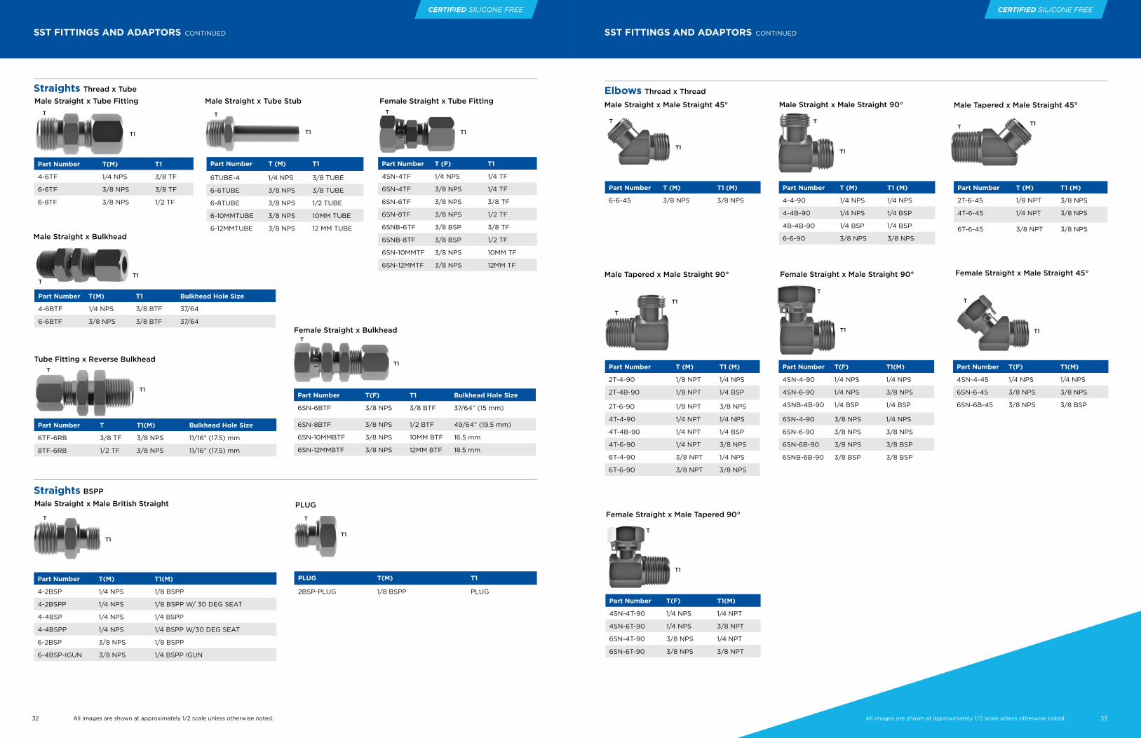
32 33All images are shown at approximately 1/2 scale unless otherwise noted.All images are shown at approximately 1/2 scale unless otherwise noted.
CERTIFIED SILICONE FREE CERTIFIED SILICONE FREE
SST FITTINGS AND ADAPTORS CONTINUED
Straights Thread x Tube
T
T1
Male Straight x Tube Fitting
Straights BSPP
Part Number T(M) T1
4-6TF 1/4 NPS 3/8 TF
6-6TF 3/8 NPS 3/8 TF
6-8TF 3/8 NPS 1/2 TF
T
T1
Male Straight x Tube Stub
Part Number T (M) T1
6TUBE-4 1/4 NPS 3/8 TUBE
6-6TUBE 3/8 NPS 3/8 TUBE
6-8TUBE 3/8 NPS 1/2 TUBE
6-10MMTUBE 3/8 NPS 10MM TUBE
6-12MMTUBE 3/8 NPS 12 MM TUBE
T
T1
Female Straight x Tube Fitting
Part Number T (F) T1
4SN-4TF 1/4 NPS 1/4 TF
6SN-4TF 3/8 NPS 1/4 TF
6SN-6TF 3/8 NPS 3/8 TF
6SN-8TF 3/8 NPS 1/2 TF
6SNB-6TF 3/8 BSP 3/8 TF
6SNB-8TF 3/8 BSP 1/2 TF
6SN-10MMTF 3/8 NPS 10MM TF
6SN-12MMTF 3/8 NPS 12MM TF
T
Male Straight x Male British Straight
Part Number T(M) T1(M)
4-2BSP 1/4 NPS 1/8 BSPP
4-2BSPP 1/4 NPS 1/8 BSPP W/ 30 DEG SEAT
4-4BSP 1/4 NPS 1/4 BSPP
4-4BSPP 1/4 NPS 1/4 BSPP W/30 DEG SEAT
6-2BSP 3/8 NPS 1/8 BSPP
6-4BSP-IGUN 3/8 NPS 1/4 BSPP IGUN
PLUG
PLUG T(M) T1
2BSP-PLUG 1/8 BSPP PLUG
Female Straight x Bulkhead
Part Number T(F) T1 Bulkhead Hole Size
6SN-6BTF 3/8 NPS 3/8 BTF 37/64” (15 mm)
6SN-8BTF 3/8 NPS 1/2 BTF 49/64” (19.5 mm)
6SN-10MMBTF 3/8 NPS 10MM BTF 16.5 mm
6SN-12MMBTF 3/8 NPS 12MM BTF 18.5 mm
T
Tube Fitting x Reverse Bulkhead
Part Number T T1(M) Bulkhead Hole Size
6TF-6RB 3/8 TF 3/8 NPS 11/16” (17.5) mm
8TF-6RB 1/2 TF 3/8 NPS 11/16” (17.5) mm
T1
T
T1
T
T1
SST FITTINGS AND ADAPTORS CONTINUED
Elbows Thread x Thread
T
Part Number T (M) T1 (M)
6-6-45 3/8 NPS 3/8 NPS
T1
Male Straight x Male Straight 90°
Part Number T (M) T1 (M)
2T-4-90 1/8 NPT 1/4 NPS
2T-4B-90 1/8 NPT 1/4 BSP
2T-6-90 1/8 NPT 3/8 NPS
4T-4-90 1/4 NPT 1/4 NPS
4T-4B-90 1/4 NPT 1/4 BSP
4T-6-90 1/4 NPT 3/8 NPS
6T-4-90 3/8 NPT 1/4 NPS
6T-6-90 3/8 NPT 3/8 NPS
T
T1
T
T1
Female Straight x Male Straight 45°
Part Number T(F) T1(M)
4SN-4-45 1/4 NPS 1/4 NPS
6SN-6-45 3/8 NPS 3/8 NPS
6SN-6B-45 3/8 NPS 3/8 BSP
Male Tapered x Male Straight 45°
Part Number T (M) T1 (M)
2T-6-45 1/8 NPT 3/8 NPS
4T-6-45 1/4 NPT 3/8 NPS
6T-6-45 3/8 NPT 3/8 NPS
Part Number T (M) T1 (M)
4-4-90 1/4 NPS 1/4 NPS
4-4B-90 1/4 NPS 1/4 BSP
4B-4B-90 1/4 BSP 1/4 BSP
6-6-90 3/8 NPS 3/8 NPS
Male Tapered x Male Straight 90°
T T1
T
T1
T
T1
Female Straight x Male Straight 90°
Part Number T(F) T1(M)
4SN-4-90 1/4 NPS 1/4 NPS
4SN-6-90 1/4 NPS 3/8 NPS
4SNB-4B-90 1/4 BSP 1/4 BSP
6SN-4-90 3/8 NPS 1/4 NPS
6SN-6-90 3/8 NPS 3/8 NPS
6SN-6B-90 3/8 NPS 3/8 BSP
6SNB-6B-90 3/8 BSP 3/8 BSP
T
T1
Female Straight x Male Tapered 90°
Part Number T(F) T1(M)
4SN-4T-90 1/4 NPS 1/4 NPT
4SN-6T-90 1/4 NPS 3/8 NPT
6SN-4T-90 3/8 NPS 1/4 NPT
6SN-6T-90 3/8 NPS 3/8 NPT
Male Straight x Male Straight 45°
Male Straight x Bulkhead
Part Number T(M) T1 Bulkhead Hole Size
4-6BTF 1/4 NPS 3/8 BTF 37/64
6-6BTF 3/8 NPS 3/8 BTF 37/64
TT1
T1
33All images are shown at approximately 1/2 scale unless otherwise noted.

34 35All images are shown at approximately 1/2 scale unless otherwise noted.All images are shown at approximately 1/2 scale unless otherwise noted.
CERTIFIED SILICONE FREE CERTIFIED SILICONE FREE
SST FITTINGS AND ADAPTORS CONTINUED
Elbows Thread x Tube
T
T1
Part Number T (M) T1
6-6TF-90 3/8 NPS 3/8 TF
6-8TF-90 3/8 NPS 1/2 TF
Male Straight x Tube Fitting 90°
T1
T
Female Straight x Tube Fitting 90°
Part Number T (F) T1
6SN-10MMTF-90 3/8 NPS 10MM TF
6SN-6TF-90 3/8 NPS 3/8 TF
6SN-8TF-90 3/8 NPS 1/2 TF
T
T1
Part Number T (M) T1
6-6BTF-90 3/8 NPS 3/8 BTF
Male Straight x Bulkhead 90°
T
T1
Part Number T (F) T1
6SN-10MMBTF-90 3/8 NPS 3/8 BTF
6SN-6BTF-90 3/8 NPS 3/8 BTF
Female Straight x Bulkhead 90°
T
T1
Part Number T (M) T1
6-6BTF-45 3/8 NPS 3/8 BTF
Male Straight x Bulkhead 45°
T
T1
Part Number T (F) T1
6SN-6BTF-45 3/8 NPS 3/8 BTF
Female Straight x Bulkhead 45°
Caps
T
Female Straight
Brand Specific
Part Number T (F)
4-CAP 1/4 NPS
4B-CAP 1/4 BSP
6-CAP 3/8 NPS
6B-CAP 3/8 BSP
T
Male Straight
Part Number T (M)
4-PLUG 1/4 NPS
6-PLUG 3/8 NPS
Male Tapered
Part Number T (M)
4T-PLUG 1/4 NPT
Male Straight x DR-1 (for inlet to Ransburg DR-1 family of fluid regulators)
Part Number T T1
DR1-2-4 1/4 NPS DR1 Inlet
Short AW Fitting Male Straight x Male British Straight Part Number T T1
4-2BSP-AWS 1/4 NPS 1/8 BSP
4-4BSP-AWS 1/4 NPS 1/4 BSP
Long AW Fitting Male Straight x Male British Straight
Part Number T T1
4-2BSP-AWL 1/4 NPS 1/8 BSP
Plugs
T
T1
T
T1
T1
T
T
T1
Part Number T T1
4-2BSP-AWL-A 1/4 NPS 1/8 BSP
TEES
T1T
Male Straight x Male Straight x Male Straight
Part Number T (M) T1 (M) T2 (M)
6-6-6 3/8 NPS 3/8 NPS 3/8 NPS
6B-6B-6B 3/8 BSP 3/8 BSP 3/8 BSP
T2
T1T
Male Straight x Male Straight x Female Straight
Part Number T (M) T1 (M) T2 (F)
6-6-6SN 3/8 NPS 3/8 NPS 3/8 NPS
T2
T1T
Female Straight x Female Straight x Female Straight
T2
Part Number T (F) T1 (F) T2 (F)
6SN-6SN-6SN 3/8 NPS 3/8 NPS 3/8 NPS
6SNB-6SNB-6SNB 3/8 BSP 3/8 BSP 3/8 BSP
T1T
Female Straight x Male Straight x Male StraightT2
Part Number T (F) T1 (M) T2 (M)
6SN-6-6 3/8 NPS 3/8 NPS 3/8 NPS
6SNB-6B-6B 3/8 BSP 3/8 BSP 3/8 BSP
T1T
Female Straight x Tube Fitting x Female Tapered
T2
Part Number T (F) T1 T2 (F)
6SN-6TF-4T(F) 3/8 NPS 3/8 TF 1/4 NPT
T1T
Male Straight X Male Straight X Male Tapered T2
Part Number T (M) T1 (M) T2 (M)
6-6-4T 3/8NPS 3/8NPS 1/4 NPT
6-6-6T 3/8NPS 3/8NPS 3/8 NPT
Hosco compact Tees product family is designed for use in piping systems to provide sampling or monitoring ports, or to provide multiple inlet or outlet ports to name a few uses. The Tees are available in standard tee and bulkhead tee configurations, and generally in 1/4” or 3/8” NPS/BSPP(PF) male or female swivel nut, 1/4” or 3/8” NPT/BSPT(PT), 3/8” or 1/2” Tube Stubs or metric equivalents, 3/8” TF or BTF compression or bulkhead compression (or metric equivalents) styles, or JIC style. Our flexible designs allow any combination of these to meet the application.
Feature and BenefitsMultiple Configurations
• NPT/BSPT(PT), NPS/BSPP(PF), Compression, JIC, and Tube Stub connection points
SST Construction
• Long life
Unique Manufacturing Processes
• Unique processing provides chemical free passivation and absolutely clean product for installation
Cavity Free & Smooth Bore Design
• To minimize material pack out or “dirt in paint” and provide easy to clean and flush components
Low Shear Design
• Large flow passageways minimize shear and coating degradation and subsequent pressure or flowrate losses

36 37All images are shown at approximately 1/2 scale unless otherwise noted.
CERTIFIED SILICONE FREE
TEES CONTINUED
T1T
Male Straight X Male Straight X Female Tapered
Part Number T (M) T1 (M) T2 (F)
6-6-4T(F) 3/8 NPS 3/8 NPS 1/4 NPT
T2
T1T
Female Straight X Male Straight X Male Tapered
Part Number T (F) T1 (M) T2 (M)
6SN-6-4T 3/8 NPS 3/8 NPS 3/8 NPT
6SN-6-6T 3/8 NPS 3/8 NPS 3/8 NPT
T2
T1T
Female Straight X Bulkhead Tube Fitting X Female Straight
Part Number T (F) T1 T2 (F)
6SN-6BTF-6SN 3/8 NPS 3/8 BTF 3/8 NPS
T2
T1T
Female Straight X Male Straight X Female Straight
T2Part Number T (F) T1 (M) T2 (F)
6SN-6-4SN 3/8 NPS 3/8 NPS 1/4NPS
6SN-6-6SN 3/8 NPS 3/8 NPS 3/8 NPS
6SNB-6B-6SNB 3/8 BSP 3/8 BSP 3/8 BSP
T1T
Female Straight X Female Straight X Male Straight
Part Number T (F) T1 (F) T2 (M)
6SN-6SN-6 3/8 NPS 3/8 NPS 3/8 NPS
T2
PRESSURE GAUGE
Part Number T
PG-300-4T 1/4" NPT (M)
PG-300-4T(F) 1/4" NPT (F)
PG-200-4T 1/4" NPT (M)
PG-200-4T(F) 1/4" NPT (F)
PG-160-4T 1/4" NPT (M)
PG-160-4T(F) 1/4" NPT (F)
T
COMPRESSION FITTINGS — FRACTIONAL INCH
Part Number Description
2T-4TF 1/8” NPT(M) x 1/4” TF
4T-4TF 1/4” NPT(M) x 1/4” TF
6T-4TF 3/8” NPT(M) x 1/4” TF
8T-4TF 1/2” NPT(M) x 1/4” TF
2T-6TF 1/8” NPT(M) x 3/8” TF
4T-6TF 1/4” NPT(M) x 3/8” TF
6T-6TF 3/8” NPT(M) x 3/8” TF
8T-6TF 1/2” NPT(M) x 3/8” TF
4T-8TF 1/4” NPT(M) x 1/2” TF
6T-8TF 3/8” NPT(M) x 1/2” TF
8T-8TF 1/2” NPT(M) x 1/2” TF
8T-10TF 1/2” NPT(M) x 5/8” TF
8T-12TF 1/2” NPT(M) x 3/4” TF
12T-10TF 3/4” NPT(M) x 5/8” TF
12T-12TF 3/4” NPT(M) x 3/4” TF
12T-16TF 3/4” NPT(M) x 1” TF
16T-16TF 1” NPT(M) x 1” TF
20T-20TF 1 1/4” NPT(M) x 1 1/4” TF
24T-24TF 1 1/2” NPT(M) x 1 1/2” TF
32T-32TF 2” NPT(M) x 2” TF
Male Connector
Part Number Description
2T-4TF-90 1/8” NPT(M) x 1/4” TF 90
4T-4TF-90 1/4” NPT(M) x 1/4” TF 90
6T-4TF-90 3/8” NPT(M) x 1/4” TF 90
8T-4TF-90 1/2” NPT(M) x 1/4” TF 90
2T-6TF-90 1/8” NPT(M) x 3/8” TF 90
4T-6TF-90 1/4” NPT(M) x 3/8” TF 90
6T-6TF-90 3/8” NPT(M) x 3/8” TF 90
8T-6TF-90 1/2” NPT(M) x 3/8” TF 90
4T-8TF-90 1/4” NPT(M) x 1/2” TF 90
6T-8TF-90 3/8” NPT(M) x 1/2” TF 90
8T-8TF-90 1/2” NPT(M) x 1/2” TF 90
8T-10TF-90 1/2” NPT(M) x 5/8” TF 90
8T-12TF-90 1/2” NPT(M) x 3/4” TF 90
12T-10TF-90 3/4” NPT(M) x 5/8” TF 90
12T-12TF-90 3/4” NPT(M) x 3/4” TF 90
12T-16TF-90 3/4” NPT(M) x 1” TF 90
16T-16TF-90 1” NPT(M) x 1” TF 90
16T-20TF-90 1” NPT(M) x 1 1/4” TF 90
1 1/4” NPT(M) x 1 1/4” TF 90
24T-24TF-90 1 1/2” NPT(M) x 1 1/2” TF 90
32T-32TF-90 2” NPT(M) x 2” TF 90
Male 90° Elbow
Part Number Description
4TF-4TF 1/4” TF x 1/4” TF
6TF-6TF 3/8” TF x 3/8” TF
8TF-8TF 1/2” TF x 1/2” TF
10TF-10TF 5/8” TF x 5/8” TF
12TF-12TF 3/4” TF x 3/4” TF
16TF-16TF 1” TF x 1” TF
20TF-20TF 1 1/4” TF x 1 1/4” TF
24TF-24TF 1 1/2” TF x 1 1/2” TF
32TF-32TF 2” TF x 2” TF
Union
Part Number Description4TF-6TF 1/4” TF x 3/8” TF
4TF-8TF 1/4” TF x 1/2” TF
6TF-8TF 3/8” TF x 1/2” TF
6TF-10TF 3/8” TF x 5/8” TF
8TF-10TF 3/8” TF x 5/8” TF
6TF-12TF 3/8” TF x 3/4” TF
8TF-12TF 1/2” TF x 3/4” TF
10TF-12TF 5/8” TF x 3/4” TF
8TF-16TF 1/2” TF x 1” TF
12TF-16TF 3/4” TF x 1” TF
Reducing Union
Part Number Description
4TF-4TF-90 1/4” TF x 1/4” TF 90
6TF-6TF-90 3/8” TF x 3/8” TF 90
8TF-8TF-90 1/2” TF x 1/2” TF 90
10TF-10TF-90 5/8” TF x 5/8” TF 90
12TF-12TF-90 3/4” TF x 3/4” TF 90
16TF-16TF-90 1” TF x 1” TF 90
20TF-20TF-90 1 1/4” TF x 1 1/4” TF 90
24TF-24TF-90 1 1/2” TF x 1 1/2” TF 90
32TF-32TF-90 2” TF x 2” TF 90
Union 90° Elbow
Tube x Tube
Part Number T T1
HY-8-6-6 1/2 OD 3/8 OD
HY-10-8-8 5/8 OD 1/2 OD
HY-12-8-8 3/4 OD 1/2 OD
T
T1 T1
Image is Approx. 1/4 Scale
Hosco provides the highest quality 316 Stainless Steel Compression & Instrumentation Fittings for installation into paint and coating applications. These compression tube fittings have heat code traceability and our quality raw materials come from US, France, and Italy. Third party testing from TUV proves our intermixability with the other industry leaders. Hosco can offer technical assistance and training on these fittings which are fully gaugeable with the same installation and remake instructions as the other top tier suppliers of these two ferrule compression fittings.
Feature and BenefitsWide Array of Sizes Configurations• Availability of all known Paint
Circulation design connections for SST Paint Circ Systems
Local Inventory Commitment• Able to supply from inventory
and maintain a safety stock of unusual sizes used in Paint Circ System designs
Custom Assemblies with Hosco’s Core Product Lines• Hosco can “kit up” compression
fittings, ball valves, hoses and fittings needed to reduce prep time while on the jobsite, reducing labor costs on the project
Certified Silicone Free• As always, all materials supplied
by Hosco are “Certified Silicone and Contaminant Free” for installation into the Paint Circ System
Features• 1/4” NPT(M) or (F) 316 SST
• Top mount or back mount
• 0-160 PSI (0-11 BAR) or 0-200 PSI (0-14 BAR) or 0-300 PSI (0-21 BAR)
• 2-1/2” gauge face dia.
• Glycerine filled
• Glass face
CERTIFIED SILICONE FREE

38 39All images are shown at approximately 1/2 scale unless otherwise noted.All images are shown at approximately 1/2 scale unless otherwise noted.
CERTIFIED SILICONE FREE CERTIFIED SILICONE FREE
Part Number Description2T(F)-4TF-90 1/8” NPT(F) x 1/4” TF 90
4T(F)-4TF-90 1/4” NPT(F) x 1/4” TF 90
4T(F)-6TF-90 1/4” NPT(F) x 3/8” TF 90
6T(F)-6TF-90 3/8” NPT(F) x 3/8” TF 90
8T(F)-6TF-90 1/2” NPT(F) x 3/8” TF 90
4T(F)-8TF-90 1/4” NPT(F) x 1/2” TF 90
6T(F)-8TF-90 3/8” NPT(F) x 1/2” TF 90
8T(F)-8TF-90 1/2” NPT(F) x 1/2” TF 90
8T(F)-10TF-90 1/2” NPT(F) x 5/8” TF 90
8T(F)-12TF-90 1/2” NPT(F) x 3/4” TF 90
12T(F)-12TF-90 3/4” NPT(F) x 3/4” TF 90
16T(F)-12TF-90 1” NPT(F) x 3/4” TF 90
16T(F)-16TF-90 1” NPT(F) x 1” TF 90
Female 90° Elbow
COMPRESSION FITTINGS — FRACTIONAL INCH CONTINUED
Part Number Description4TF-4BTF 1/4” TF x 1/4” BTF
6TF-6BTF 3/8” TF x 3/8” BTF
8TF-8BTF 1/2” TF x 1/2” BTF
10TF-10BTF 5/8” TF x 5/8” BTF
12TF-12BTF 3/4” TF x 3/4” BTF
16TF-16BTF 1” TF x 1” BTF
20TF-20BTF 1 1/4” TF x 1 1/4” BTF
24TF-24BTF 1 1/2” TF x 1 1/2” BTF
Bulkhead Union
Part Number Description4TF-4TF-4TF 1/4” TF x 1/4” TF x 1/4” TF
6TF-6TF-6TF 3/8” TF x 3/8” TF x 3/8” TF
8TF-8TF-8TF 1/2” TF x 1/2” TF x 1/2” TF
10TF-10TF-10TF 5/8” TF x 5/8” TF x 5/8” TF
12TF-12TF-12TF 3/4” TF x 3/4” TF x 3/4” TF
16TF-16TF-16TF 1” TF x 1” TF x 1” TF
20TF-20TF-20TF 1 1/4” TF x 1 1/4” TF x 1 1/4” TF
24TF-24TF-24TF 1 1/2” TF x 1 1/2” TF x 1 1/2” TF
Union Tee
Part Number Description6TF-4TF-4TF 3/8” TF x 1/4” TF x 1/4” TF
8TF-4TF-4TF 1/2” TF x 1/4” TF x 1/4” TF
8TF-6TF-6TF 1/2” TF x 3/8” TF x 3/8” TF
10TF-6TF-6TF 5/8” TF x 3/8” TF x 3/8” TF
10TF-8TF-6TF 5/8” TF x 1/2” TF x 3/8” TF
10TF-8TF-8TF 5/8” TF x 1/2” TF x 1/2” TF
12TF-8TF-6TF 3/4” TF x 1/2” TF x 3/8” TF
12TF-8TF-8TF 3/4” TF x 1/2” TF x 1/2” TF
16TF-12TF-6TF 1” TF x 3/4” TF x 3/8” TF
16TF-12TF-8TF 1” TF x 3/4” TF x 1/2” TF
16TF-12TF-12TF 1” TF x 3/4”TF x 3/4”TF
20TF-16TF-16TF 1 1/4” TF x 1” TF x 1” TF
24TF-16TF-16TF 1 1/2” TF x 1” TF x 1” TF
Reducing Tees On Run and Branch
Reducing Tees On Branch
Part Number Description4TF-4TF-2T(F) 1/4” TF x 1/4” F x 1/8” NPT(F)
4TF-4TF-4T(F) 1/4” TF x 1/4” F x 1/4” NPT(F)
6TF-6TF-4T(F) 3/8” TF x 3/8” TF x 1/4” NPT(F)
6TF-6TF-6T(F) 3/8” TF x 3/8” TF x 3/8” NPT(F)
6TF-6TF-8T(F) 3/8” TF x 3/8” TF x 1/2” NPT(F)
8TF-8TF-4T(F) 1/2” TF x 1/2” TF x 1/4” NPT(F)
8TF-8TF-6T(F) 1/2” TF x 1/2” TF x 3/8” NPT(F)
8TF-8TF-8T(F) 1/2” TF x 1/2” TF x 3/8” NPT(F)
10TF-10TF-8T(F) 5/8” TF x 5/8” TF x 1/2” NPT(F)
12TF-12TF-12T(F) 3/4” TF x 3/4” TF x 3/4” NPT(F)
16TF-16TF-12T(F) 1” TF x 1” TF x 3/4” NPT(F)
16TF-16TF-16T(F) 1” TF x 1” TF x 1” NPT(F)
Female Branch Tee
Part Number Description6TF-6TF-4TF 3/8” TF x 3/8” TF x 1/4” TF
8TF-8TF-4TF 1/2” TF x 1/2” TF x 1/4” TF
8TF-8TF-6TF 1/2” TF x 1/2” TF x 3/8” TF
10TF-10TF-6TF 5/8” TF x 5/8” TF x 3/8” TF
12TF-12TF-6TF 3/4” TF x 3/4” TF x 3/8” TF
12TF-12TF-8TF 3/4” TF x 3/4” TF x 1/2” TF
16TF 16TF-6TF 1” TF x 1” TF x 3/8” TF
16TF-16TF-8TF 1” TF x 1” TF x 1/2” TF
16TF-16TF-12TF 1” TF x 1” TF x 3/4” TF
20TF-20TF-16TF 1 1/4” TF x 1 1/4” TF x 1” TF
24TF-24TF-16TF 1 1/2” TF x 1 1/2” TF x 1” TF
Part Number Description2T(F)-4TF 1/8” NPT(F) x 1/4” TF
4T(F)-4TF 1/4” NPT(F) x 1/4” TF
6T(F)-4TF 3/8” NPT(F) x 1/4” TF
8T(F)-4TF 1/2” NPT(F) x 1/4” TF
4T(F)-6TF 1/4” NPT(F) x 3/8” TF
6T(F)-6TF 3/8” NPT(F) x 3/8” TF
8T(F)-6TF 1/2” NPT(F) x 3/8” TF
4T(F)-8TF 1/4” NPT(F) x 1/2” TF
6T(F)-8TF 3/8” NPT(F) x 1/2” TF
8T(F)-8TF 1/2” NPT(F) x 1/2” TF
8T(F)-10TF 1/2” NPT(F) x 5/8” TF
8T(F)-12TF 1/2” NPT(F) x 3/4” TF
12T(F)-12TF 3/4” NPT(F) x 3/4” TF
16T(F)-16TF 1” NPT(F) x 1” TF
20T(F)-20TF 1 1/4” NPT(F) x 1 1/4” TF
24T(F)-24TF 1 1/2” NPT(F) x 1 1/2” TF
Female Connector
COMPRESSION FITTINGS — FRACTIONAL INCH CONTINUED
Part Number Description4TF-CAP 1/4” TF CLOSURE
6TF-CAP 3/8” TF CLOSURE
8TF-CAP 1/2” TF CLOSURE
10TF-CAP 5/8” TF CLOSURE
12TF-CAP 3/4” TF CLOSURE
16TF-CAP 1” TF CLOSURE
20TF-CAP 1 1/4” TF CLOSURE
24TF-CAP 1 1/2” TF CLOSURE
Tube Cap
Part Number Description4TF-PLUG 1/4”TF NUT PLUG
6TF-PLUG 3/8” TF NUT PLUG
8TF-PLUG 1/2” TF NUT PLUG
10TF-PLUG 5/8” TF NUT PLUG
12TF-PLUG 3/4” TF NUT PLUG
16TF-PLUG 1” TF NUT PLUG
20TF-PLUG 1 1/4” TF NUT PLUG
24TF-PLUG 1 1/2” TF NUT PLUG
32TF-PLUG 2” TF NUT PLUG
Tube Plug
Part Number Description4TF-6TUBE 1/4” TF X 3/8” OD TUBE STUB
4TF-8TUBE 1/4” TF X 1/2” OD TUBE STUB
4TF-10TUBE 1/4” TF X 5/8” OD TUBE STUB
4TF-12TUBE 1/4” TF X 3/4” OD TUBE STUB
6TF-4TUBE 3/8” TF X 1/4” OD TUBE STUB
6TF-8TUBE 3/8” TF X 1/2” OD TUBE STUB
6TF-10TUBE 3/8” TF X 5/8” OD TUBE STUB
6TF-12TUBE 3/8” TF X 3/4” OD TUBE STUB
8TF-4TUBE 1/2” TF X 1/4” OD TUBE STUB
8TF-6TUBE 1/2” TF X 3/8” OD TUBE STUB
8TF-12TUBE 1/2” TF X 3/4” OD TUBE STUB
8TF-16TUBE 1/2” TF X 1” OD TUBE STUB
10TF-12TUBE 5/8” TF X 3/4” OD TUBE STUB
10TF-16TUBE 5/8” TF X 1” OD TUBE STUB
12TF-8TUBE 3/4” TF X 1/2” OD TUBE STUB
12TF-16TUBE 3/4” TF X 1” OD TUBE STUB
16TF-20TUBE 1” TF X 1 1/4” OD TUBE STUB
16TF-24TUBE 1” TF X 1 1/2” OD TUBE STUB
20TF-24TUBE 1-1/4” TF X 1 1/2” OD TUBE STUB
Reducer
Part No. Description4T-4TUBE 1/4” NPT(M) X 1/4” OD TUBE STUB
4T-6TUBE 1/4” NPT(M) X 3/8” OD TUBE STUB
4T-8TUBE 1/4” NPT(M) X 1/2” OD TUBE STUB
6T-6TUBE 3/8” NPT(M) X 3/8” OD TUBE STUB
6T-8TUBE 3/8” NPT(M) X 1/2” OD TUBE STUB
6T-12TUBE 3/8” NPT(M) X 3/4” OD TUBE STUB
8T-8TUBE 1/2” NPT(M) X 1/2” OD TUBE STUB
8T-12TUBE 1/2” NPT(M) X 3/4” OD TUBE STUB
12T-12TUBE 3/4” NPT(M) X 3/4” OD TUBE STUB
12T-16TUBE 3/4” NPT(M) X 1” OD TUBE STUB
16T-16TUBE 1” NPT(M) X 1” OD TUBE STUB
20T-20TUBE 1 1/4” NPT(M) X 1 1/4” OD TUBE STUB
24T-24TUBE 1 1/2” NPT(M) X 1 1/2” OD TUBE STUB
Male Tube Stub Adapter
Port Connector
Part Number Description4-DF-SS-SET 1/4” DUAL FERRULE SET/10
6-DF-SS-SET 3/8” DUAL FERRULE SET/10
8-DF-SS-SET 1/2” DUAL FERRULE SET/10
10-DF-SS-SET 5/8” DUAL FERRULE SET/10
12-DF-SS-SET 3/4” DUAL FERRULE SET/10
16-DF-SS-SET 1” DUAL FERRULE SET/10
20-DF-SS-SET 1 1/4” DUAL FERRULE SET/10
24-DF-SS-SET 1 1/2” DUAL FERRULE SET/10
Ferrule Set (10 front/10 back)
Part Number Description4-PORT 1/4” TF PORT CONNECTOR
6-PORT 3/8” TF PORT CONNECTOR
8-PORT 1/2” TF PORT CONNECTOR
12-PORT 3/4” TF PORT CONNECTOR
16-PORT 1” TF PORT CONNECTOR
20-PORT 1 1/4” TF PORT CONNECTOR
24-PORT 1 1/2” TF PORT CONNECTOR
32-PORT 2” TF PORT CONNECTOR
Part No. Description4T(F)-4TUBE 1/4” NPT(F) x 1/4” OD TUBE STUB
4T(F)-6TUBE 1/4” NPT(F) x 3/8” OD TUBE STUB
4T(F)-8TUBE 1/4” NPT(F) x 1/2” OD TUBE STUB
6T(F)-4TUBE 3/8” NPT(F) x 1/4” OD TUBE STUB
6T(F)-6TUBE 3/8” NPT(F) x 3/8” OD TUBE STUB
6T(F)-8TUBE 3/8” NPT(F) x 1/2” OD TUBE STUB
8T(F)-8TUBE 1/2” NPT(F) x 1/2” OD TUBE STUB
8T(F)-10TUBE 1/2” NPT(F) x 5/8” OD TUBE STUB
8T(F)-12TUBE 1/2” NPT(F) x 3/4” OD TUBE STUB
12T(F)-12TUBE 3/4” NPT(F) x 3/4” OD TUBE STUB
12T(F)-16TUBE 3/4” NPT(F) x 1” OD TUBE STUB
16T(F)-16TUBE 1” NPT(F) x 1” OD TUBE STUB
20T(F)-20TUBE 1 1/4” NPT(F) x 11/4” OD TUBE STUB
Female Tube Stub Adapter
Part Number Description4-TFNSS 1/4” TUBE NUT
6-TFNSS 3/8” TUBE NUT
8-TFNSS 1/2” TUBE NUT
10-TFNSS 5/8” TUBE NUT
12-TFNSS 3/4” TUBE NUT
16-TFNSS 1” TUBE NUT
20-TFNSS 1 1/4” TUBE NUT
24-TFNSS 1 1/2” TUBE NUT
32-TFNSS 2” TUBE NUT
Nut

40 41All images are shown at approximately 1/2 scale unless otherwise noted.All images are shown at approximately 1/2 scale unless otherwise noted.
CERTIFIED SILICONE FREE CERTIFIED SILICONE FREE
COMPRESSION FITTINGS — METRIC
Hosco provides the highest quality 316 Stainless Steel Compression & Instrumentation Fittings for installation into paint and coating applications. These compression tube fittings have heat code traceability and our quality raw materials come from US, France, and Italy. Third party testing from TUV proves our intermixability with the other industry leaders. Hosco can offer technical assistance and training on these fittings which are fully gaugeable with the same installation and remake instructions as the other top tier suppliers of these two ferrule compression fittings.
Feature and BenefitsWide Array of Sizes/Configurations• Availability of all known Paint
Circulation design connections for SST Paint Circ Systems
Local Inventory Commitment• Able to supply from inventory
and maintain a safety stock of unusual sizes used in Paint Circ System designs
Custom Assemblies with Hosco’s Core Product Lines• Hosco can “kit up” compression
fittings, ball valves, hoses and fittings needed to reduce prep time while on the jobsite, reducing labor costs on the project
Certified Silicone Free• As always, all materials supplied
by Hosco are “Certified Silicone and Contaminant Free” for installation into the Paint Circ System
Part Number Description2BT-6MMTF-90 1/8" BSPT(M) x 6MMTF-90
4BT-6MMTF-90 1/4" BSPT(M) X 6MMTF-90
6BT-6MMTF-90 3/8" BSPT(M) X 6MMTF-90
8BT-6MMTF-90 1/2" BSPT(M) X 6MMTF-90
2BT-8MMTF-90 1/8" BSPT(M) X 8MMTF-90
4BT-8MMTF-90 1/4" BSPT(M) X 8MMTF-90
6BT-8MMTF-90 3/8" BSPT(M) X 8MMTF-90
8BT-8MMTF-90 1/2" BSPT(M) X 8MMTF-90
4BT-10MMTF-90 1/4" BSPT(M) X 10MMTF-90
6BT-10MMTF-90 3/8" BSPT(M) X 10MMTF-90
8BT-10MMTF-90 1/2" BSPT(M) X 10MMTF-90
4BT-12MMTF-90 1/4" BSPT(M) X 12MMTF-90
6BT-12MMTF-90 3/8" BSPT(M) X 12MMTF-90
8BT-12MMTF-90 1/2" BSPT(M) X 12MMTF-90
12BT-18MMTF-90 3/4" BSPT(M) X 18MMTF-90
16BT-25MMTF-90 1" BSPT(M) X 25MMTF-90
Male 90° Elbow Connector
Part Number Description2T-6MMTF-90 1/8"NPT(M) X 6MMTF-90
4T-6MMTF-90 1/4"NPT(M) X 6MMTF-90
6T-6MMTF-90 3/8"NPT(M) X 6MMTF-90
8T-6MMTF-90 1/2"NPT(M) X 6MMTF-90
2T-8MMTF-90 1/8"NPT(M) X 8MMTF-90
4T-8MMTF-90 1/4"NPT(M) X 8MMTF-90
6T-8MMTF-90 3/8"NPT(M) X 8MMTF-90
8T-8MMTF-90 1/2"NPT(M) X 8MMTF-90
4T-10MMTF-90 1/4"NPT(M) X 10MMTF-90
6T-10MMTF-90 3/8"NPT(M) X 10MMTF-90
8T-10MMTF-90 1/2"NPT(M) X 10MMTF-90
4T-12MMTF-90 1/4"NPT(M) X 12MMTF-90
6T-12MMTF-90 3/8"NPT(M) X 12MMTF-90
8T-12MMTF-90 1/2"NPT(M) X 12MMTF-90
12T-18MMTF-90 3/4"NPT(M) X 18MMTF-90
16T-25MMTF-90 1"NPT(M) X 25MMTF-90
24T-38MMTF-90 1 1/2"NPT(M) X 38MMTF-90
BSPT To Metric Compression
NPT To Metric Compression
Many additional sizes available; call Hosco for more information.
Part Number Description2BT-6MMTF 1/8"BSPT(M) x 6MMTF
4BT-6MMTF 1/4"BSPT(M) X 6MMTF
6BT-6MMTF 3/8"BSPT(M) X 6MMTF
8BT-6MMTF 1/2"BSPT(M) X 6MMTF
2BT-8MMTF 1/8"BSPT(M) X 8MMTF
4BT-8MMTF 1/4"BSPT(M) X 8MMTF
6BT-8MMTF 3/8"BSPT(M) X 8MMTF
8BT-6MMTF 1/2"BSPT(M) X 8MMTF
4BT-10MMTF 1/4"BSPT(M) X 10MMTF
6BT-10MMTF 3/8"BSPT(M) X 10MMTF
8BT-10MMTF 1/2"BSPT(M) X 10MMTF
4BT-12MMTF 1/4"BSPT9M) X 12MMTF
6BT-12MMTF 3/8"BSPT(M) X 12MMTF
8BT-12MMTF 1/2"BSPT(M) X 12MMTF
12BT-18MMTF 3/4"BSPT(M) X 18MMTF
16BT-25MMTF 1"BSPT(M) X 25MMTF
24BT-38MMTF 1 1/2"BSPT(M) X 38MMTF
Male Connector
BSPT To Metric Compression
NPT To Metric Compression
Part Number Description2T-6MMTF 1/8"NPT(M) X 6MMTF
4T-6MMTF 1/4"NPT(M) X 6MMTF
6T-6MMTF 3/8"NPT(M) X 6MMTF
8T-6MMTF 1/2"NPT(M) X 6MMTF
2T-8MMTF 1/8"NPT(M) X 8MMTF
4T-8MMTF 1/4"NPT(M) X 8MMTF
6T-8MMTF 3/8"NPT(M) X 8MMTF
8T-8MMTF 1/2"NPT(M) X 8MMTF
4T-10MMTF 1/4"NPT(M) X 10MMTF
6T-10MMTF 3/8"NPT(M) X 10MMTF
8T-10MMTF 1/2"NPT(M) X 10MMTF
4T-12MMTF 1/4"NPT(M) X 12MMTF
6T-12MMTF 3/8"NPT(M) X 12MMTF
8T-12MMTF 1/2"NPT(M) X 12MMTF
12T-18MMTF 3/4"NPT(M) X 18MMTF
16T-25MMTF 1"NPT(M) X 25MMTF
24T-38MMTF 1 1/2"NPT(M) X 38MMTF
COMPRESSION FITTINGS — METRIC CONTINUED
Part Number Description6MMTF-6MMTF 6MMTF X 6MMTF
8MMTF-8MMTF 8MMTF X 8MMTF
10MMTF-10MMTF 10MMTF X 10MMTF
12MMTF-12MMTF 12MMTF X 12MMTF
14MMTF-14MMTF 14MMTF X 14MMTF
16MMTF-16MMTF 16MMTF X 16MMTF
18MMTF-18MMTF 18MMTF X 18MMTF
20MMTF-20MMTF 20MMTF X 20MMTF
22MMTF-22MMTF 22MMTF X 22MMTF
25MMTF-25MMTF 25MMTF X 25MMTF
38MMTF-38MMTF 38MMTF X 38MMTF
50MMTF-50MMTF 50MMTF X 50MMTF
Union
Part Number Description6MMTF-8MMTF 6MMTF x 8MMTF6MMTF-10MMTF 6MMTF x 10MMTF6MMTF-12MMTF 6MMTF x 12MMMTF8MMTF-10MMTF 8MMTF x 10MMTF8MMTF-12MMTF 8MMTF x 12MMTF10MMTF-12MMTF 10MMTF x 12MMTF10MMTF-16MMTF 10MMTF x 16MMTF12MMTF-16MMTF 12MMTF x 16MMTF12MMTF-18MMTF 12MMTF x 18MMTF18MMTF-25MMTF 18MMTF x 25MMTF20MMTF-25MMTF 20MMTF x 25MMTF20MMTF-38MMTF 20MMTF x 38MMTF25MMTF-38MMTF 24MMTF x 38MMTF
Reducing Union
Part Number Description6MMTF-6MMTF-90 6MMTF X 6MMTF 90
8MMTF-8MMTF-90 8MMTF X 8MMTF 90
10MMTF-10MMTF-90 10MMTF X 10MMTF 90
12MMTF-12MMTF-90 12MMTF X 12MMTF 90
14MMTF-14MMTF-90 14MMTF X 14MMTF 90
16MMTF-16MMTF-90 16MMTF X 16MMTF 90
18MMTF-18MMTF-90 18MMTF X 18MMTF 90
20MMTF-20MMTF-90 20MMTF X 20MMTF 90
22MMTF-22MMTF-90 22MMTF X 22MMTF 90
25MMTF-25MMTF-90 25MMTF X 25MMTF 90
38MMTF-38MMTF-90 38MMTF X 38MMTF 90
50MMTF-50MMTF-90 50MMTF X 50MMTF 90
Union 90° Elbow
Part Number Description6MMTF-6MMBTF 6MMTF X 6MMBTF
8MMTF-8MMBTF 8MMTF X 8MMBTF
10MMTF-10MMBTF 10MMTF X 10MMBTF
12MMTF-12MMBTF 12MMTF X 12MMBTF
14MMTF-14MMBTF 14MMTF X 14MMBTF
16MMTF-16MMBTF 16MMTF X 16MMBTF
18MMTF-18MMBTF 18MMTF X 18MMBTF
20MMTF-20MMBTF 20MMTF X 20MMBTF
25MMTF-25MMBTF 25MMTF X 25MMBTF
38MMTF-38MMBTF 35MMTF X 38MMBTF
Bulkhead Union
Many additional sizes available; call Hosco for more information.
Female Connector
Part Number Description2T(F)-6MMTF 1/8" NPT(F) X 6MMTF
4T(F)-6MMTF 1/4" NPT(F) X 6MMTF
6T(F)-6MMTF 3/8" NPT(F) X 6MMTF
8T(F)-6MMTF 1/2" NPT(F) X 6MMTF
2T(F)-8MMTF 1/8" NPT(F) X 8MMTF
4T(F)-8MMTF 1/4" NPT(F) X 6MMTF
6T(F)-8MMTF 3/8" NPT(F) X 8MMTF
8T(F)-8MMTF 1/2" NPT(F) X 8MMTF
4T(F)-10MMTF 1/4" NPT(F) X 10MMTF
6T(F)-10MMTF 3/8" NPT(F) X 10MMTF
8T(F)-10MMTF 1/2" NPT(F) X 10MMTF
4T(F)-12MMTF 1/4" NPT(F) X 12MMTF
6T(F)-12MMTF 3/8" NPT(F) X 12MMTF
8T(F)-12MMTF 1/2" NPT(F) X 12MMTF
12T(F)-12MMTF 3/4" NPT(F) X 18MMTF
16T(F)-25MMTF 1" NPT(F) X 25MMTF
NPT To Metric Compression
BSPT To Metric Compression
Part Number Description2BT(F)-6MMTF 1/8" BSPT(F) X 6MMTF
4BT(F)-6MMTF 1/4" BSPT(F) X 6MMTF
6BT(F)-6MMTF 3/8" BSPT(F) X 6MMTF
8BT(F)-6MMTF 1/2" BSPT(F) X 6MMTF
2BT(F)-8MMTF 1/8" BSPT(F) X 8MMTF
4BT(F)-8MMTF 1/4" BSPT(F) X 6MMTF
6BT(F)-8MMTF 3/8" BSPT(F) X 8MMTF
8BT(F)-8MMTF 1/2" BSPT(F) X 8MMTF
4BT(F)-10MMTF 1/4" BSPT(F) X 10MMTF
6BT(F)-10MMTF 3/8" BSPT(F) X 10MMTF
8BT(F)-10MMTF 1/2" BSPT(F) X 10MMTF
4BT(F)-12MMTF 1/4" BSPT(F) X 12MMTF
6BT(F)-12MMTF 3/8" BSPT(F) X 12MMTF
8BT(F)-12MMTF 1/2" BSPT(F) X 12MMTF
12BT(F)-12MMTF 3/4" BSPT(F) X 18MMTF
16BT(F)-25MMTF 1" BSPT(F) X 25MMTF
41All images are shown at approximately 1/2 scale unless otherwise noted.

42 43All images are shown at approximately 1/2 scale unless otherwise noted.All images are shown at approximately 1/2 scale unless otherwise noted.
CERTIFIED SILICONE FREE CERTIFIED SILICONE FREE
Part Number Description6MM-TFNSS 6MM TUBE NUT8MM-TFNSS 8MM TUBE NUT10MM-TFNSS 10MM TUBE NUT12MM-TFNSS 12MM TUBE NUT14MM-TFNSS 14MM TUBE NUT16MM-TFNSS 16MM TUBE NUT18MM-TFNSS 18MM TUBE NUT20MM-TFNSS 20MM TUBE NUT22MM-TFNSS 22MM TUBE NUT25MM-TFNSS 25MM TUBE NUT38MM-TFNSS 38MM TUBE NUT50MM-TFNSS 50MM TUBE NUT
COMPRESSION FITTINGS — METRIC CONTINUED
Many additional sizes available; call Hosco for more information.
Part Number Description8MMTF-8MMTF-8MMTF 8MMTF x 8MMTF x 8MMTF
10MMTF-10MMTF-10MMTF 10MMTF x 10MMTF x 10MMTF
12MMTF-12MMTF-12MMTF 12MMTF x 12MMTF x 12MMTF
14MMTF-14MMTF-14MMTF 14MMTF x 14MMTF x 14MMTF
16MMTF-16MMTF-16MMTF 16MMTF x 16MMTF x 16MMTF
18MMTF-18MMTF-18MMTF 18MMTF x 18MMTF x 18MMTF
20MMTF-20MMTF-20MMTF 20MMTF x 20MMTF x 20MMTF
22MMTF-22MMTF-22MMTF 22MMTF x 22MMTF x 22MMTF
25MMTF-25MMTF-25MMTF 25MMTF x 25MMTF x 25MMTF
38MMTF-38MMTF-38MMTF 38MMTF x 38MMTF x 38MMTF
50MMTF-50MMTF-50MMTF 50MMTF x 50MMTF x 50MMTF
Union Tee Reducing Tees On Branch
Part Number Description8MMTF-8MMTF-6MMTF 8MMTF X 8MMTF X 6MMTF
10MMTF-10MMTF-6MMTF 10MMTF X 10MMTF X 6MMTF
12MMTF-12MMTF-6MMTF 12MMTF X 12MMTF X 6MMTF
12MMTF-12MMTF-10MMTF 12MMTF X 12MMTF x 10MMTF
14MMTF-14MMTF-10MMTF 14MMTF X 14MMTF X 10MMTF
18MMTF-18MMTF-12MMTF 18MMTF X 18MMTF X 12MMTF
50MMTF-50MMTF-38MMTF 50MMTF X 50MMTF X 38MMMTF
Part Number Description6MMTF-6MMTF-2T(F) 6MMTF x 6MMTF X 1/8 NPT F6MMTF-6MMTF-4T(F) 6MMTF x 6MMTF X 1/4" NPT F8MMTF-8MMTF-2T(F) 8MMTF x 8MMTF X 1/8 NPT F8MMTF-8MMTF-4T(F) 8MMTF x 8MMTF X 1/4" NPT F10MMTF-10MMTF-4T(F) 10MMTF x 10MMTF X 1/4" NPT F10MMTF-10MMTF-6T(F) 10MMTF x 10MMTF X 3/8" NPT F 12MMTF-12MMTF-4T(F) 12MMTF x 12MMTF X 1/4" NPT F12MMTF-12MMTF-6T(F) 12MMTF x 12MMTF X 3/8 NPT F12MMTF-12MMTF-8T(F) 12MMTF x 12MMTF X 1/2" NPT F 16MMTF-16MMTF-8T(F) 16MMTF x 16MMTF X 1/2 NPT F
Female Branch Tee
Part Number Description2T(F)-6MMTF-90 1/8" NPT(F) x 6MMTF 90
4T(F)-6MMTF-90 1/4" NPT(F) x 6MMTF 90
4T(F)-8MMTF-90 1/4" NPT(F) x 8MMTF 90
4T(F)-10MMTF-90 1/4" NPT(F) x 10MMTF 90
4T(F)-12MMTF-90 1/4" NPT(F) x 12MMTF 90
8T(F)-12MMTF-90 1/2" NPT(F) x 12MMTF 90
8T(F)-16MMTF-90 1/2" NPT(F) x 12MMTF 90
Female 90° Elbow
NPT To Metric Compression
COMPRESSION FITTINGS — METRIC CONTINUED
Part Number Description8MMTF-CAP 8MMTF CLOSURE10MMTF-CAP 10MMTF CLOSURE12MMTF-CAP 12MMTF CLOSURE14MMTF-CAP 14MMTF CLOSURE16MMTF-CAP 16MMTF CLOSURE18MMTF-CAP 18MMTF CLOSURE20MMTF-CAP 20MMTF CLOSURE22MMTF-CAP 22MMTF CLOSURE25MMTF-CAP 25MMTF CLOSURE38MMTF-CAP 38MMTF CLOSURE
Tube Cap
Part Number Description8MM-PLUG 8MMTF NUT PLUG10MM-PLUG 10MMTF NUT PLUG12MM-PLUG 12MMTF NUT PLUG14MM-PLUG 14MMTF NUT PLUG16MM-PLUG 16MMTF NUT PLUG18MM-PLUG 18MMTF NUT PLUG20MM-PLUG 20MMTF NUT PLUG22MM-PLUG 22MMTF NUT PLUG25MM-PLUG 25MMTF NUT PLUG38MM-PLUG 38MMTF NUT PLUG50MM-PLUG 50MMTF NUT PLUG
Tube Plug
Part Number Description6MMTF-8MMTUBE 6MMTF X 8MM TUBE STUB6MMTF-10MMTUBE 6MMTF X 10MM TUBE STUB8MMTF-6MMTUBE 8MMTF X 6MM TUBE STUB8MMTF-10MMTUBE 8MMTF X 10MM TUBE STUB8MMTF-12MMTUBE 8MMTF X 12MM TUBE STUB10MMTF-6MMTUBE 10MMTF X 6MM TUBE STUB10MMTF-8MMTUBE 10MMTF X 8MM TUBE STUB10MMTF-12MMTUBE 10MMTF X 12MM TUBE STUB12MMTF-6MMTUBE 12MMTF X 6MM TUBE STUB12MMTF-8MMTUBE 12MMTF X 8MM TUBE STUB12MMTF-10MMTUBE 12MMTF X 10MM TUBE STUB12MMTF-16MMTUBE 12MMTF X 16MM TUBE STUB16MMTF-12MMTUBE 16MMTF X 12MM TUBE STUB18MMTF-16MMTUBE 18MMTF X 16MM TUBE STUB18MMTF-20MMTUBE 18MMTF X 20MM TUBE STUB18MMTF-22MMTUBE 18MMTF X 22MM TUBE STUB18MMTF-25MMTUBE 18MMTF X 25MM TUBE STUB25MMTF-18MMTUBE 25MMTF X 18MM TUBE STUB25MMTF-20MMTUBE 25MMTF X 20MM TUBE STUB
Reducer
Part No. Description2BT-6MMTUBE 1/8"BSPT(M) X 6MMTUBE4BT-6MMTUBE 1/4"BSPT(M) X 6MMTUBE2BT-8MMTUBE 1/8"BSPT(M) X 8MMTUBE4BT-8MMTUBE 1/4"BSPT(M) X 8MMTUBE6BT-8MMTUBE 3/8"BSPT(M) X 8MMTUBE8BT-8MMTUBE 1/2"BSPT(M) X 8MMTUBE4BT-10MMTUBE 1/4"BSPT(M) X 10MMTUBE6BT-10MMTUBE 3/8"BSPT(M) X 10MMTUBE8BT-10MMTUBE 1/2"BSPT(M) X 10MMTUBE4BT-12MMTUBE 1/4"BSPT(M) X 12MMTUBE6BT-12MMTUBE 3/8"BSPT(M) X 12MMTUBE
8BT-12MMTUBE 1/2"BSPT(M) X 12MMTUBE12BT-20MMTUBE 3/4"BSPT(M) X 20MMTUBE
Male Tube Stub Adapter
Part Number Description6MM-DF-SS-SET 6MM DUAL FERRULE SET/108MM-DF-SS-SET 8MM DUAL FERRULE SET/1010MM-DF-SS-SET 10MM DUAL FERRULE SET/1012MM-DF-SS-SET 12MM DUAL FERRULE SET/1014MM-DF-SS-SET 14MM DUAL FERRULE SET/1016MM-DF-SS-SET 16MM DUAL FERRULE SET/1018MM-DF-SS-SET 18MM DUAL FERRULE SET/1020MM-DF-SS-SET 20MM DUAL FERRULE SET/1022MM-DF-SS-SET 22MM DUAL FERRULE SET/1025MM-DF-SS-SET 25MM DUAL FERRULE SET/1038MM-DF-SS-SET 38MM DUAL FERRULE SET/1050MM-DF-SS-SET 50MM DUAL FERRULE SET/10
Ferrule Set (10 front/10 back)
Port Connector
Part Number Description6MM-PORT 6MMTF PORT CONNECTOR8MM-PORT 8MMTF PORT CONNECTOR10MM-PORT 10MMTF PORT CONNECTOR12MM-PORT 12MMTF PORT CONNECTOR14MM-PORT 14MMTF PORT CONNECTOR16MM-PORT 16MMTF PORT CONNECTOR18MM-PORT 18MMTF PORT CONNECTOR25MM-PORT 25MMTF PORT CONNECTOR38MM-PORT 38MMTF PORT CONNECTOR
Nut
Many additional sizes available; call Hosco for more information.

44 45All images are shown at approximately 1/2 scale unless otherwise noted.
CERTIFIED SILICONE FREECERTIFIED SILICONE FREE
PREFISTM STAINLESS STEEL CONNECTORS FOR TUBE
Straight Union Reducing Union
90° Elbow
Union Tees
Part Number Description
HPTF-3232-32-SS TEE - SS - 2 X 2 X 2
HPTF-2424-24-SS TEE - SS - 1 1/2 X 1 1/2 X 1 1/2
HPTF-2020-20-SS TEE - SS - 1 1/4 X 1 1/4 X 1 1/4
HPTF-1616-16-SS TEE - SS - 1 X 1 X 1
HPTF-1212-12-SS TEE - SS - 3/4 X 3/4 X 3/4
HPTF-0808-08-SS TEE - SS - 1/2 X 1/2 X 1/2
Part Number Description
HPTF-2424-06-SS RTEE - SS - 2424 - 06
HPTF-2424-08-SS RTEE - SS - 2424 - 08
HPTF-2424-10-SS RTEE - SS - 2424 -10
HPTF-2020-06-SS RTEE - SS - 2020 - 06
HPTF-2020-08-SS RTEE - SS - 2020 - 08
HPTF-2020-10-SS RTEE - SS - 2020 - 10
HPTF-1616-06-SS RTEE - SS - 1616 - 06
HPTF-1616-08-SS RTEE - SS - 1616 - 08
HPTF-1616-10-SS RTEE - SS - 1616 - 10
HPTF-1212-06-SS RTEE - SS - 1212 - 06
HPTF-1212-08-SS RTEE - SS - 1212 - 08
HPTF-1212-10-SS RTEE - SS - 1212 - 10
Part Number Description
HPTF-2420-06-SS RTEE - SS - 2420 - 06
HPTF-2420-08-SS RTEE - SS - 2420 - 08
HPTF-2420-10-SS RTEE - SS - 2420 - 10
HPTF-2016-06-SS RTEE - SS - 2016 - 06
HPTF-2016-08-SS RTEE - SS - 2016 - 08
HPTF-2016-10-SS RTEE - SS - 2016 - 10
HPTF-1612-06-SS RTEE - SS - 1612 - 06
HPTF-1612-08-SS RTEE - SS - 1612 - 08
HPTF-1612-10-SS RTEE - SS - 1612 - 10
Reducing Tees On Branch
Reducing Tees On Run and Branch
Open ToolFor use with tubing.
PREFISTM CONNECTORS
Advantages• Reduced Installation time:
Complete a 2” carbon steel fitting in 40 seconds per side; 3” in 90 seconds per side
• Less effort: No PST sealant, gaskets, o-rings or welding required
• Resistance to high pressures, temperatures and chemicals
• Available in various configurations and dimensions
Pipe/Tube DiameterCarbon steel 3/8” – 3.5” (10.0 – 88.9 mm)
Stainless steel
3/8” – 3.0” (10.0 – 76.1 mm)
Temperature Range -67°F – 572°F (-55°C – 400°C)
PressuresCarbon steel up to 9137 psi (630 bar) operating pressure
Stainless steel up to 3770 psi (260 bar) operating pressure
Installing new or modifying existing piping systems for process fluids such as paint or high viscosity sealer header systems has never been faster or easier than with the Hosco PreFiS connector family of products.
Available in 316 SST wetted parts for paint or process fluids and carbon steel for high pressure systems, the PreFiS system of connectors is a full line of couplings, reducing couplings, tees, reducing tees, lateral wyes, and others to provide smooth-bore, cavity and silicone-free, and low shear operation–the attributes which serve as Hosco’s cornerstone of design.
Unpressed Condition
Press rings
Coupling Sleeve
Slide Rings
Pipe
Tooling The installation of the press fitting is done with the help of a press tool and a high pressure pump. Our press tools come in an open or closed configuration, are easy to handle, and can be used in narrow spaces satisfying the tight center-to-center requirements.
Components PreFiS products consist of a cylindrical body with a cogged inner surface and two press ring sets. It only takes a few seconds to crimp the fitting onto the pipe.
Pressed Condition
Pressed Condition (cross section)
No PST sealant, gaskets, o-rings, or welding required for a clean and secure installation of the PreFiS connectors. Approvals
Power UnitFor use with open tool.
Part Number Description
HPTF-0606-SS UNION - SS - 3/8 X 3/8
HPTF-0808-SS UNION - SS - 1/2 X 1/2
HPTF-1212-SS UNION - SS - 3/4 X 3/4
HPTF-1616-SS UNION - SS - 1 X 1
HPTF-2020-SS UNION - SS - 1 1/4 X 1 1/4
HPTF-2424-SS UNION - SS - 1 1/2 X 1 1/2
HPTF-3232-SS UNION - SS - 2 X 2
HPTF-4040-SS UNION - SS - 2 1/2 X 2 1/2
HPTF-4848-SS UNION - SS - 3 X 3
HPTF-5656-SS UNION - SS - 3 1/2 X 3 1/2
Part Number Description
HPTF-1612-SS REDUCER - SS - 1 X 3/4
HPTF-2016-SS REDUCER - SS - 1 1/4 X 1
HPTF-2420-SS REDUCER - SS - 1 1/2 X 1 1/4
HPTF-3224-SS REDUCER - SS - 2 X 1 1/2
HPTF-4032-SS REDUCER - SS - 2 1/2 X 2
Part Number Description
HPTF-EL-0606-SS ELBOW - SS - 3/8 X 3/8
HPTF-EL-0808-SS ELBOW - SS - 1/2 X 1/2
HPTF-EL-1212-SS ELBOW - SS - 3/4 X 3/4
HPTF-EL-1616-SS ELBOW - SS - 1 X 1
HPTF-EL-2020-SS ELBOW - SS - 1 1/4 X 1 1/4
HPTF-EL-2424-SS ELBOW - SS - 1 1/2 X 1 1/2
HPTF-EL-3232-SS ELBOW - SS - 2 X 2
HPTF-EL-4040-SS ELBOW - SS - 2 1/2 X 2 1/2
HPTF-EL-4848-SS ELBOW - SS - 3 X 3
HPTF-EL-5656-SS ELBOW - SS - 3 1/2 X 3 1/2
45All images are shown at approximately 1/2 scale unless otherwise noted.

47
CERTIFIED SILICONE FREE
46 All images are shown at approximately 1/2 scale unless otherwise noted.
CERTIFIED SILICONE FREE
PREFISTM CONNECTORS FOR PIPE
Straight Union Reducing Union
Part Number Description
HPPF-1612-•• REDUCER - •• - 1 X 3/4
HPPF-2016-•• REDUCER - •• - 1 1/4 X 1
HPPF-2420-•• REDUCER - •• - 1 1/2 X 1 1/4
HPPF-3224-•• REDUCER - •• - 2 X 1 1/2
HPPF-4032-•• REDUCER - •• - 2 1/2 X 2
HPPF-4832-•• REDUCER - •• - 3 X 2
Part Number Description
HPPF-0606-•• UNION - •• - 3/8 X 3/8
HPPF-0808-•• UNION - •• - 1/2 X 1/2
HPPF-1212-•• UNION - •• - 3/4 X 3/4
HPPF-1616-•• UNION - •• - 1 X 1
HPPF-2020-•• UNION - •• - 1 1/4 X 1 1/4
HPPF-2424-•• UNION - •• - 1 1/2 X 1 1/2
HPPF-3232-•• UNION - •• - 2 X 2
HPPF-4040-•• UNION - •• - 2 1/2 X 2 1/2
HPPF-4848-•• UNION - •• - 3 X 3
Closed ToolFor use with pipe.
Power UnitCan be used with open or closed tool.
BUNDLED TUBING SYSTEMS
8M ID Piggable Hose Bundle with Ancillary Support Hose and Tubes
Rotary Atomizer Control Bundle with Unique Hose and Tube Markings
Robotic Paint and Air Supply Bundle Pneumatic/Air Pilot Bundle-24 Lines
Robot/Automation BundlesPart No. Description
HOA-40405 Hose Bundle: (4) NP-5 Natural lines marked S1, S2, R1, R2 for Paint lines
HOA-41947 Hose Bundle: (5) NHA-0302 , (2) NHA-375275 Custom Printed
HOA-42283 Hose Bundle: (1) NHA-0504, (5) NHA-0403, (3) NHA-0806 Custom Printed, 265 ft. reel
HOA-42284 Hose Bundle: (5) NHA-532332, (1) NHA-375275 Custom Printed and/or Colors
HOA-42285 Hose Bundle: (2) NHA-532332, (1) NHA-0403, (1) NHA-375275 Custom Printed
HOA-42346 Hose Bundle: (3) NHA-0302 , (2) NHA-0504 , (2) NHA-375275
Custom Printed
HOA-42347 Hose Bundle: (7) NHA-0302 , (4) NHA-375275 2 , 2 ,
(1) NHA-0504-BL , (2) NHA-0403 Custom Printed
HOA-42348 Hose Bundle: (2) NHA-0504 , (2) PTFM-8x6, (5) NHA-0302 ,
(2) FEP-0302, (2) NHA-375275 , (3) NHA-0403 Custom Printed
HOA-43257 Hose Bundle: (2) NHA-375275, (1) NHA-532332 Custom Printed
HOA-44725 Hose Bundle: (1) NHA-532332, (1) NHA-375275, (2) NHA-10X7 , (2) FEP-0503
Custom Printed and Colors
HOA-44726 Hose Bundle: (4) NHA-532332, (4) NHA-6x4, (5) NHA-8x6, (2) FEPM-8x6
Custom Printed and Colors
HOA-45065 Hose Bundle: (4) NHA-375275, (2) NHA-532332 Custom Printed
HOA-45389 Hose Bundle: (7) NHA-0403 , (2) NHA-0806 ,
(2) NHA-375275 , (1) NHA-0504Y Custom Printed
HOA-45451 Hose Bundle: (6) NHA-8x6, (4) NHA-6x4, (8) NHA-4x2.7 Custom Printed
HOA-45613B Hose Bundle: (5) NHA-4x2.7, (2) NHA-8x6, (3) NHA-375275 Custom Printed
HOA-45614A Hose Bundle: (4) FEP-0503, (1) FEP-0806
R B N G BL B N
BL G B BL G B N
GY W R B N BL R N
BL B N
G W BLRBOR W
RB R BW
RB
G YR B N BL R BL
G B Y
S G B
90° Elbow
Part Number Description
HPPF-EL-0606-•• ELBOW - •• - 3/8 X 3/8
HPPF-EL-0808-•• ELBOW - •• - 1/2 X 1/2
HPPF-EL-1212-•• ELBOW - •• - 3/4 X 3/4
HPPF-EL-1616-•• ELBOW - •• - 1 X 1
HPPF-EL-2020-•• ELBOW - •• - 1 1/4 X 1 1/4
HPPF-EL-2424-•• ELBOW - •• - 1 1/2 X 1 1/2
HPPF-EL-3232-•• ELBOW - •• - 2 X 2
HPPF-EL-4040-•• ELBOW - •• - 2 1/2 X 2 1/2
HPPF-EL-4848-•• ELBOW - •• - 3 X 3
NOTE: •• Indicates material. When ordering, please specify SS for Stainless and CS for Carbon.
Union Tees
Part Number Description
HPPF-4848-48-•• TEE - •• - 3 X 3 X 3
HPPF-3232-32-•• TEE - •• - 2 X 2 X 2
HPPF-2424-24-•• TEE - •• - 1 1/2 X 1 1/2 X 1 1/2
HPPF-2020-20-•• TEE - •• - 1 1/4 X 1 1/4 X 1 1/4
HPPF-1616-16-•• TEE - •• - 1 X 1 X 1
HPPF-1212-12-•• TEE - •• - 3/4 X 3/4 X 3/4
HPPF-0808-08-•• TEE - •• - 1/2 X 1/2 X 1/2
Part Number Description
HPPF-2424-06-•• RTEE - •• - 2424 - 06
HPPF-2424-08-•• RTEE - •• - 2424 - 08
HPPF-2424-10-•• RTEE - •• - 2424 -10
HPPF-2020-06-•• RTEE - •• - 2020 - 06
HPPF-2020-08-•• RTEE - •• - 2020 - 08
HPPF-2020-10-•• RTEE - •• - 2020 - 10
HPPF-1616-06-•• RTEE - •• - 1616 - 06
HPPF-1616-08-•• RTEE - •• - 1616 - 08
HPPF-1616-10-•• RTEE - •• - 1616 - 10
HPPF-1212-06-•• RTEE - •• - 1212 - 06
HPPF-1212-08-•• RTEE - •• - 1212 - 08
HPPF-1212-10-•• RTEE - •• - 1212 - 10
Reducing Tees On Branch
Part Number Description
HPPF-2420-06-•• RTEE - •• - 2420 - 06
HPPF-2420-08-•• RTEE - •• - 2420 - 08
HPPF-2420-10-•• RTEE - •• - 2420 - 10
HPPF-2016-06-•• RTEE - •• - 2016 - 06
HPPF-2016-08-•• RTEE - •• - 2016 - 08
HPPF-2016-10-•• RTEE - •• - 2016 - 10
HPPF-1612-06-•• RTEE - •• - 1612 - 06
HPPF-1612-08-•• RTEE - •• - 1612 - 08
HPPF-1612-10-•• RTEE - •• - 1612 - 10
Reducing Tees On Run and Branch
Hosco has pioneered the Bundled Tubing applications for paint shops and paint operations. The use of bundled tubing significantly increases hose and tubing life versus loose lines in cat-tracks or cable-trays where motion is present- as much as 8-10 times longer life. In addition, incorporating the proprietary jacket cover that resists chaffing, cracking and all know solvents and paints provides a scuff guard and provides containment should there be a hose or tubing release or failure in the bundle for any reason. Hosco can specifically engineer a bundle up to a jacket diameter of approximately 1 ½” and have supplied up to 18 interior lines (24 for air pilots) of various colors, resin types (FEP, PTFE, or Nylon-PA) in up to 530 feet continuous coils or cut lengths as specified. Custom laylines identifying each interior line can be done, as well as private label marking of the interior lines or outside jacket for a relatively small cost increase.
Feature and BenefitsCustom Engineering Capabilities
• Hosco can provide an unlimited combination of hose and tubing sizes, colors, hose markings and resins to provide quick identification of lines in the bundle for maintenance actions in up to 530 feet long coils
Great Value for Operations
• With up to 8-10 times longer life and enhances safety of nesting the hoses and tubes in a strong, solvent and chemical resistant exterior jacket to prevent loose line failures encountered in competitive options
Better Hose and Tubing Management
• Cat-tracks, cable-trays and other hose routing stay neater and cleaner as opposed to the normal accumulation of overspray onto all loose lines and the housekeeping mess that is created from using loose lines in the spray area
More Compact Routing
• More lines per square inch can be provided in cat-track, cable-trays or hose ducts so these devices could be downsized to enhance booth air flow or lower costs

48 49
CERTIFIED SILICONE FREE CERTIFIED SILICONE FREE
Part Number DescriptionHOA-18862 Hose Bundle: (4) NHA-532322 Natural lines marked CP-1 thru CP-4
HOA-18317 Hose Bundle: (6) NHA-532322 Natural lines marked CP-1 thru CP-6
HOA-42146 Hose Bundle: (8) NHA-532332 Natural lines marked CP1-CP8
HOA-43282 Hose Bundle: (9) NHA-532332 Natural Lines marked CP-1-CP-9
HOA-42769 Hose Bundle: (12) NHA-0302 Natural Lines marked CP-1 thru CP-12
Pneumatic/Pilot Bundles
BUNDLED TUBING SYSTEMS CONTINUED
For application engineering a custom bundle for your application:
Email [email protected]
Call (248) 912-1750.
Part Number Description
HOA-43795 Piggable hose, tri-layer, 22MM OD X 12MM ID Polyurethane/FEP tubing, 1000
Ft. Reels maximum length
HOA-43796 Piggable hose, tri-layer, 14MM OD X 8MM ID Polyurethane/FEP tubing, 1000 Ft.
Reels maximum length
HOA-43797 Piggable hose bundle, tri-layer 14MM OD X 8MM ID Polyurethane/FEP pig line,
(2) FEP-0604, (1) NHA-375275R, (2) NHA-4x2.7 Pilot Lines, 250 foot Reel
Piggable Hoses and Bundles
Part Number Description
HOA-45970 PVC jacketed bundle with (10) PHA-532332 tubes Custom Colors
HOA-43638 Twinline polyurethane red 5/32 OD X .075” ID, blue 1/4 OD X .125” ID
Other Bundles
HOSE MANAGEMENT – CAT TRACK ASSEMBLY
The Hosco hose and tubing puller kit is designed to pull hose and tube through cat-tracks and cable-tray. Maintenance staff, Pipefitters, Robot Operators can easily add or replace damaged hoses using this tool kit. The kit includes most common metric or fractional inch hose and tubing sizes with an engineered barb to hold during the toughest situations. The outside diameter of the fitting matches that of the hose being pulled to eliminate hang-ups while pulling. A hole is designed into the center of the tool to allow for pulling existing lines without replacement. Twine and a hose cutter are also included in a handy toolbox to complete this kit.
Feature and BenefitsSmooth Barrel Design• Eliminate hang-ups and pull the
replacement hose easier, saving time and effort
Stainless Steel Construction• Strong tool with high hose
retention will not wear out through uses
Multiple Sizes Available • Versatile tool for all cattrack or
cabletray/duct pulls regardless of the size of the old vs new hose
Engineered Barb• Large hold strength for the
bends and long pulls, eliminating multiple tries
MAINTENANCE TOOLS
Individual Parts
Included Tool Sizes
9MM ID x 9MM ID
9MM ID x 8MM ID
9MM ID x 7MM ID
9MM ID x 6MM ID
8MM ID x 8MM ID
8MM ID x 7MM ID
8MM ID x 6MM ID
7MM ID x 7MM ID
7MM ID x 6MM ID
6MM ID x 6MM ID
6MM ID x 4MM ID
3/8” ID x 3/8” ID
3/8” ID x 1/4” ID
1/4” ID x 1/4 ID
1/4” ID x 3/16” ID
3/16” ID x 3/16” ID
Other sizes available, please define size and type of hose or tubing, and quantity required for a quote.
Hose and Tube Puller Kit Part Number Description
CKIDHSP Hose and Tube Puller Kit*
Straight
Reducing
* Kit includes one tool of each size listed below, a hose and tubing cutter, and 250’ of twine, all in a compact tool box.
The new 38SN-EXT tool was developed to assist installers in the connection of any 3/8” NPS(F) swivel nut fitting or hose connector to a 3/8” NPS(M) connection point. Paint station designs are more compact and more densely packed at the booth side that creates problems of access to the connection points. This tool alleviates the need to get your hand into the area and attempt to turn a wrench to complete the connection. With the 38SN-EXT the connection can be made with the 12-16” ratchet style extension tool to move your installation activity away from the confluence of hoses.
To use this tool, place the stationary 7/8” hex body on the ball valve end you are connecting to, and then nest the hose and hose connection into the internal socket and drive it down to the connection point. Using a customer supplied 1/2” ratchet, tighten the hose connector while stabilizing the ball valve outer housing to prevent rotating the ball valve during hose connector installation. Generally tighten to 30-35 ft/lbs to insure long term leak free connection.
Swivel Nut Extension Tool
Part Number Description
38SN-EXT Swivel Nut Extension Tool
In addition to bundled tubing and assemblies for hose management, Hosco is a certified reseller of Gortrac and IGUS cattracks, allowing for a complete cattrack assembly for replaced or rebuilt robotic stations. Hosco has worked with some of the world’s leading integrators and OEMs to assemble and deliver complete cat tracks, cable trays, ducting systems, machine and handgun stations to the job site. Working with our customer’s requirements, each hose or tube can be labeled and outfitted with Hosco hose fittings to make for an easy, plug-in-ready installation at the job site.
CERTIFIED SILICONE FREE

50 51
CERTIFIED SILICONE FREE CERTIFIED SILICONE FREE
SHROUD CLEANER UPGRADES AND REMOTE-MOUNT REGULATOR KIT
Shroud cleaners in any coating application can be a primary source of “dirt” and surface defects if not properly and continuously maintained, which stems from increasing production and manpower demands.
Hosco has engineered a solution to reduce the maintenance schedule and eliminate many of those defects, freeing up maintenance staff to focus on other issues.
Common IssuesPaint Build-up, Inside and Out• Hosco Solution:
Conductive PTFE (Teflon™) coating reduces frequency of cleaning and disassembly
Plugged Drains• Hosco Solution:
Enlarge and relocate drain to most appropriate position based on shroud cleaner model
Excessive Solvent Pressure Can flood applicator and shroud, preventing adequate drying and allowing contaminants to force behind and around the shroud and bell cup
• Hosco Solutions:
Regulate pressure to the cap cleaner to ensure level is within shroud cleaner specifications
Assembly for deadheaded or systems with circulating heated solvent
Difficult to Monitor and Maintain• Hosco Solutions:
Remote mount regulator outside of booth to access and monitor with ease
Quick disconnect kit for the air ring, easing serviceability
Hosco will work with your engineers or maintenance staff to customize a solution to meet your needs for your particular application and shroud cleaner.
This data is an example of OEM verified quality improvement data due to our Cap Cleaner upgrade program.
Spits Per Shift
70
60
50
40
30
20
10
0Original Specification Modified Cleaner
Known weak points in existing system installations:As spray defects are analyzed in the Paint Shop Operations, it’s often found that the spray gun bell washers are identified as a source of these defects, which may vary in size and severity.
Below are some of the problems from an applicator cleaner installation and/or operation generally ranked on product quality impact from least complicated/serious to the most complicated/serious.
Problems due to a dirty applicator:1. E-stat faults – E-stat faults occur when a drips or build-up on a dirty applica-
tor causes a short in the spray operation.
2. Mist from cleaner operation – Small droplets of paint, waste paint or solvent are splashed onto the product or form a mist which settles onto the product due to the turbulent cleaning operation and proximity of the vessel to the product being painted.
3. Solvent drips on product – Generally caused by insufficient blow off during the exiting of the cleaning station, plugged drains contributing to the exces-sive fluid within the collection vessel, or overfeeding solvent during the wash.
4. Dirt in paint – Particles of dried paint fall into the wet film during the spraying step between cleaning periods in non-catalyzed material spray operations
5. Poor paint application – If a dirty applicator does not cause a fault, uneven paint build-up or streaking may result.
Outside of Dirty Applicator Cleaner Inside of Dirty Applicator Cleaner
ELIMINATING THE DIRTY APPLICATOR
Hosco SolutionsHosco is a recognized solutions provider with proven results when it comes to removing defects associated with a dirty applicator. Hosco has been involved in applicator cleaning projects with a few robot stations to entire high-volume plants. A project eliminating the repair/rework of spray defects plus maintenance of the cleaning stations has created enormous savings for plants on an annual basis. With a large cost savings range between project types, all users can benefit from an optimized solution.
Hosco works with many major manufacturers of applicator cleaners in North America and can supply optimized applicator cleaners to insure fast, efficient, and complete cleaning of the applicator. No matter how small or large your operations, you want to reduce spray defects and minimize time and attention required to your cleaners.
51

52 53
CERTIFIED SILICONE FREE CERTIFIED SILICONE FREE
Why Do You Clean The Applicator?Operators of automated Paint Shops know that problems come from a dirty or wet applicator in proximity to the products being sprayed, especially horizontal surfaces. The purpose of cleaning the applicator is to remove those potential defects by cleaning the exterior and fully drying it at predetermined intervals while the automation is idle between jobs. These intervals can be set by a trained operator, and some of the factors to be considered in setting these are:
• The color change demands. Some colors or materials will require more frequent cleaning intervals, or the user may want to automatically clean the applicator in a change from one color to another depending on past experiences.
• Conductivity of the material being sprayed and electrostatic “wrap” are two major factors that affect this determination of cleaning intervals.
• Solids content and the material’s propensity to coagulate or agglomerate into larger particle sizes.
• Facilities and process factors such as environmental (humidity for example), mechanical (booth air flow, spray pressures/flowrates, material temperatures (paint & solvent, etc.)
What Do You Need To Do To Optimize Performance Of The Applicator Cleaner?Air And Solvent Pressure And Flowrate Controls Regardless of the brand or model of the applicator cleaner, air and solvent dispense pressure and flowrate controls are a principal factor in the performance. Both pressures and flowrate must be controlled to manufacturers specifications and ensured that they are consistent. Too high or too low of either pressure or flowrate will result in inefficiencies and ultimately spray defects.
Air & Solvent Dispensing Temperatures Using elevated temperature cleaning solvents (waterborne) and drying air can significantly increase cleaning performance and potentially reduce solvent and compressed air usage and time in the cleaning step. Hosco recommends using elevated temperatures up to 130 F for both the waterborne solvent fluid and drying air for the most efficient and effective cleaning.
Routine Maintenance Of The Cleaning Stations The applicator cleaners must also be disassembled for thorough cleaning of the internals. The frequency of this cleaning is highly dependent on the specific materials running through the cleaner, the environment or location of the cleaner, and it’s use rate.
A poorly set up and maintained applicator cleaner will cause as many defects as it prevents.
While not directly affecting the painting process,
maintenance support of the applicator cleaner
station is necessary.
It is important to set up the frequency of automatic
cleaning properly to prevent overloading the
cleaning station’s ability to properly clean the
applicator, and to provide proper drain timing of
the purge fluids in these short durations of cleaning
operation.
How Do You Maximize Effectiveness Of The Applicator Cleaner And Minimize Maintenance?The following steps of performance improvements for these applicator cleaners is summarized into logical feature areas with descriptions.
Conductive PTFE Coating:• Reduces the cleaning and disassembly frequency by improving the
internal and external surfaces to shed overspray, splashes, and ultimately waste sticking and drying onto those surfaces. It is important due to safety regulations to insure the coating applied is conductive to minimize electrical risks in the spray zone.
Drain Modifications:• Enlarge and relocate drains for venting and quick removal of purge material
during the cleaning or color change operation. Hosco recommends a 2” NPT port at the lowest section of the collection tank with couplings for easy make and break access during inspection and maintenance.
Using Solvent Supply Recirculation with Heat Applied to the Flush Solvent:• Hosco recommends elevated temperature flush solvents (manufacturer
specific) for waterborne purge materials (i.e. deionized water with amine) to facilitate the cleaning cycle and minimize the time and solvent used in this cleaning operation.
Using Fluid Pressure and Fluid Flowrate Control at the Cleaning Station:• The supply pressure of the cleaning station should not exceed the
manufacturer’s specifications to prevent migration of solvent fluid into applicator areas that are not protected or could be harmed by the cleaning solvent.
• The supply volume of cleaning solvent should not exceed the manufacturer’s specified flowrates at any time during the spraying or wash down of the applicator and should be run at the lowest flowrate possible to perform cleaning.
• With two main options of supplying solvent to the applicator cleaner, both of which depend on purge material and temperature required, Hosco has developed a kit to enable monitoring of solvent pressure at the bulkhead wall.
• Waterborne heated purge material will require circulation at the point of use (applicator cleaner) due to minimal amount of solvent used during a typical cycle when optimized.
Tool-Less Drying Ring QD:• Hosco supplies Cleaning Station equipment (Crystal Cap Cleaner only) with
drying rings that require no tools for removal and swap out, making for quick and easy changeout with no special skills or tools required. This includes solvent fluid and drying air Quick Disconnects, and knurled knobs to remove and retain the drying ring.
Conductive PTFE Coating:
Drain Modifications:
Using Fluid Pressure and Fluid Flowrate control at the Cleaning station:
Supply Recirculation Monoline Coaxial Hose Assembly:
ELIMINATING THE DIRTY APPLICATOR ELIMINATING THE DIRTY APPLICATOR
52
If your experiences with these systems leaves you
searching for improvement of these important
secondary or sub-system equipment operations
noted above, or if you are not an automatic station
equipment user of an applicator cleaner, please
consult with your Hosco representative to get an
assessment of possible improvements.

54 55
You can reach us anytime at [email protected]
The Unique Blend of Imagination and Engineering. Hosco prides itself in its core values to listen and learn from the marketplace and customers, and many of our products were born from ideas or solutions to problems that were started by our customers.
As shown below, many of the challenges we have faced and overcome in the paint handling and paint circulation arena were started by a customer asking us, “What if we do it this way?” or “Can you make something like this?”.
We perpetually simplify and streamline product configurations to provide larger solution modules or assemblies that benefit the customer through faster installation, improved performance, longer life or reduced support or maintenance requirements.
Please accept our invitation to challenge us or work with us to provide better solutions in our product areas of expertise, which are broadening to include more initiatives in “dirt in paint” and more broadly in elimination of contaminants in the entire painting operations.
Bell Washer Optimization Project to reduce spray
defects from Bell and increase time between
housekeeping and service intervals, plus
tool free connections for the blow off ring.
Hosco is a finishing system components manufacturer serving the finishing industry worldwide through systems integrators, and an extensive network of regional authorized distributors and agents.
Hosco offers standardized capability for circulation systems and application finishing on a global basis while being the only supplier of both inch and metric smooth-bore, cavity free and microfinished valves and fittings designed specifically for paint.
All Hosco products are certified “silicone free” and ready for installation in your paint systems.
Part Number
Male Female Size Type Description
2T 2T(F) 1/8 NPT National Pipe Taper
4T 4T(F) 1/4 NPT National Pipe Taper
6T 6T(F) 3/8 NPT National Pipe Taper
8T 8T(F) 1/2 NPT National Pipe Taper
2BT 2BT(F) 1/8 BSPT British Standard Pipe Taper
4BT 4BT(F) 1/4 BSPT British Standard Pipe Taper
6BT 6BT(F) 3/8 BSPT British Standard Pipe Taper
4 4SN 1/4 NPS National Pipe Straight
6 6SN 3/8 NPS National Pipe Straight
4B 4SNB 1/4 BSP British Standard Pipe
6B 6SNB 3/8 BSP British Standard Pipe
4RB 4SN 1/4 RB Nps Reverse Bulkhead
6RB 6SN 3/8 RB Nps Reverse Bulkhead
4RBB 4SNB 1/4 RBB Bsp Reverse Bulkhead
6RBB 6SNB 3/8 RBB Bsp Reverse Bulkhead
2TUBE 2TF 1/8 Tube Tube Compression
4TUBE 4TF 1/4 Tube Tube Compression
6TUBE 6TF 3/8 Tube Tube Compression
8TUBE 8TF 1/2 Tube Tube Compression
10MMTUBE 10MMTF 10MM Tube Tube Compression
12MMTUBE 12MMTF 12MM Tube Tube Compression
4TUBE 4BTF 1/4 Bulkhead Bulkhead Tube Compression
6TUBE 6BTF 3/8 Bulkhead Bulkhead Tube Compression
8TUBE 8BTF 1/2 Bulkhead Bulkhead Tube Compression
10MMTUBE 10MMBTF 10MM Bulkhead Bulkhead Tube Compression
12MMTUBE 12MMBTF 12MM Bulkhead Bulkhead Tube Compression
Common Paint System Connections
H-Valve panel to supply two robots from a single
paint station drop, bulkhead plate mounted and delivered as a single
module for installation.
Hosco PA series of non- conductive hose connectors
for ungrounded or electrostatic spray
applications delivers the highest level of safety and
hose retention performance.
Pre-Constructed, cleaned and ready to install
Restrictor Station to simulate pressure loss in an
active station to keep the flow and pressure in balance in a paint circulation system.
Sometimes great ideas and solutions start on a scrap of paper
Imagineering - Hosco Style Global ReachAt Hosco we think globally but act locally
Hosco stands ready with the products, the service, and the expertise to deliver clean, contaminate-free paints and coatings... whether you are located next door or on the other side of the world.

©2021 Carlisle Fluid Technologies, Inc. | Binks® is a registered trademark of Carlisle Fluid Technologies, Inc. | i-Flow™ and SmartHP ™ are trademarks of Carlisle Fluid Technologies, Inc. | Models and specifications subject to change without notice. All rights reserved. | Form No. 07-210-01
CarlisleFT.com
North America +1 800 992-4657 [email protected] +44 (0) 1202 571111 [email protected] +86 21 33730108 [email protected] +81 045 785-6434 [email protected]
The brands you trustCarlisle Fluid Technologies, a wholly-owned subsidiary of Carlisle Companies Incorporated, is dedicated to providing customers industry-leading solutions for the supply, control, application and curing of a wide range of paints, powders, sealants, adhesives and other application materials. From manual finishing equipment, to highly automated mass-production installations, the company solves customers’ material application challenges through the combination of product innovation and decades of technical expertise. Focused on efficient, cost-effective global solutions for the transportation and other industrial markets, the company offers an expanding collection of pioneering product brands – BGK™, Binks®, DeVilbiss®, Hosco®, ms® and Ransburg®.
Let’s start a conversationWe want to work together to help answer your application challenges. To learn more about what we can offer, visit our website at CarlisleFT.com or call us today.
For further technical information, refer to the service bulletins available at CarlisleFT.com
youtube.com/CarlisleFluidTechnologiesGlobal
@CarlisleFT
linkedin.com/company/Carlisle-Fluid-Technologies