
GLOBAL REGISTRY - UNECE · ECE/TRANS/180/Add.4 25 January 2007 GLOBAL REGISTRY Created on 18...
126
ECE/TRANS/180/Add.4 25 January 2007 GLOBAL REGISTRY Created on 18 November 2004, pursuant to Article 6 of the AGREEMENT CONCERNING THE ESTABLISHING OF GLOBAL TECHNICAL REGULATIONS FOR WHEELED VEHICLES, EQUIPMENT AND PARTS WHICH CAN BE FITTED AND/OR BE USED ON WHEELED VEHICLES (ECE/TRANS/132 and Corr.1) Done at Geneva on 25 June 1998 Addendum Global technical regulation No. 4 TEST PROCEDURE FOR COMPRESSION-IGNITION (C.I.) ENGINES AND POSITIVE- IGNITION (P.I.) ENGINES FUELLED WITH NATURAL GAS (NG) OR LIQUEFIED PETROLEUM GAS (LPG) WITH REGARD TO THE EMISSION OF POLLUTANTS (Established in the Global Registry on 15 November 2006) UNITED NATIONS
Transcript of GLOBAL REGISTRY - UNECE · ECE/TRANS/180/Add.4 25 January 2007 GLOBAL REGISTRY Created on 18...
ECE/TRANS/180/Add.4 25 January 2007
GLOBAL REGISTRY
Created on 18 November 2004, pursuant to Article 6 of the AGREEMENT CONCERNING THE ESTABLISHING OF GLOBAL TECHNICAL
REGULATIONS FOR WHEELED VEHICLES, EQUIPMENT AND PARTS WHICH CAN BE FITTED AND/OR BE USED ON WHEELED VEHICLES
(ECE/TRANS/132 and Corr.1) Done at Geneva on 25 June 1998
Addendum
Global technical regulation No. 4
TEST PROCEDURE FOR COMPRESSION-IGNITION (C.I.) ENGINES AND POSITIVE-IGNITION (P.I.) ENGINES FUELLED WITH NATURAL GAS (NG) OR LIQUEFIED PETROLEUM GAS (LPG) WITH REGARD TO THE EMISSION OF POLLUTANTS
(Established in the Global Registry on 15 November 2006)
UNITED NATIONS

ECE/TRANS/180/Add.4 page 3
TABLE OF CONTENTS Page
A. STATEMENT OF TECHNICAL RATIONALE AND JUSTIFICATION.................5 B. TEXT OF THE REGULATION ..................................................................................7 1. Purpose .........................................................................................................................7
2. Scope ............................................................................................................................7
3. Definitions, symbols and abbreviations .......................................................................7
4. General requirements....................................................................................................14
5. Performance requirements............................................................................................14
6. Test conditions..............................................................................................................19
7. Test procedures.............................................................................................................24 8. Emission measurement and calculation........................................................................38 9. Measurement equipment ..............................................................................................61 ANNEXES Annex 1 WHTC engine dynamometer schedule.............................................................87
Annex 2.1 European diesel reference fuel .........................................................................100
Annex 2.2 United States of America diesel reference fuel 2-D.........................................101
Annex 3 Measurement equipment ..................................................................................102
Annex 4 Determination of system equivalence...............................................................119
Annex 5 Carbon flow check............................................................................................121
Annex 6 Example of calculation procedure ....................................................................124

ECE/TRANS/180/Add.4 page 4 A. STATEMENT OF TECHNICAL RATIONALE AND JUSTIFICATION 1. TECHNICAL AND ECONOMIC FEASIBILITY The objective of this proposal is to establish a harmonized global technical regulation (gtr) covering the type-approval procedure for heavy-duty engine exhaust emissions. The basis will be the test procedure developed by the WHDC informal group of GRPE (see the informal document No. 4 distributed during the forty-sixth GRPE session). Regulations governing the exhaust emissions from heavy-duty engines have been in existence for many years but the test cycles and methods of emissions measurement vary significantly. To be able to correctly determine the impact of a heavy-duty vehicle on the environment in terms of its exhaust pollutant emissions, a laboratory test procedure, and consequently the gtr, needs to be adequately representative of real-world vehicle operation. The proposed regulation is based on new research into the world-wide pattern of real heavy commercial vehicle use. From the collected data, two representative test cycles, a transient test cycle (WHTC) with both cold and hot start requirements and a hot start steady state test cycle (WHSC), have been created covering typical driving conditions in the European Union (EU), the United States of America, Japan and Australia. Alternative emission measurement procedures have been developed by an expert committee in ISO and have been published in ISO 16183. This standard reflects exhaust emissions measurement technology with the potential for accurately measuring the pollutant emissions from future low emission engines. This work has been the basis for future Japanese and the EU emission legislation. In parallel, substantial work has been undertaken on a different basis in the last several years in the United States of America to make major improvements to the emissions measurement procedures, testing protocols, and regulatory structure for both highway heavy-duty and non-road heavy-duty engines. This work is documented in the rulemaking of the United States of America and was published on 13 July 2005. Some of those new testing protocols are already reflected in this gtr. It is recognized by the Contracting Parties to the 1998 Agreement that a long-term goal for highway heavy-duty diesel engine testing and non-road diesel engine testing would be gtrs which are similar in structure and substance with respect to measurement equipment, procedures and requirements. Therefore, the Contracting Parties recognize there will be a need in the future to amend this gtr in order to have as much commonality as is possible between the highway heavy-duty diesel gtr and the non-road diesel gtr currently under development. As discussed below, this gtr does not contain emission limit values. When this gtr is amended in the future to include limit values, that may be the appropriate time to reconcile any substantive differences between the world-wide heavy-duty certification procedure (WHDC) gtr and the future gtr on non-road mobile machinery (NRMM). At this stage, the limit values shall be developed by the Contracting Parties according to their own rules of procedure.
ECE/TRANS/180/Add.4 page 5
The WHTC and WHSC test procedures reflect world-wide on-road heavy-duty engine operation, as closely as possible, and provide a marked improvement in the realism of the test procedure for measuring the emission performance of existing and future heavy-duty engines. In summary, the test procedure was developed so that it would be: (a) representative of world-wide on-road vehicle operations, (b) able to provide the highest possible level of efficiency in controlling on-road emissions, (c) corresponding to state-of-the-art testing, sampling and measurement technology, (d) applicable in practice to existing and foreseeable future exhaust emissions abatement
technologies, and (e) capable of providing a reliable ranking of exhaust emission levels from different engine
types. At this stage, the gtr is being presented without limit values. In this way, the test procedure can be given a legal status, based on which the Contracting Parties are required to start the process of implementing it into their national law. The gtr contains several options, whose adoption is left to the discretion of the Contracting Parties. Those options are related to the hot soak procedure between the cold and hot WHTC, the weighting factor of cold and hot WHTC, the particulate filter material and size, and the reference fuel. However, these aspects have to be fully harmonized when common limit values are established. When implementing the test procedure contained in this gtr as part of their national legislation or regulation, Contracting Parties are invited to use limit values which represent at least the same level of severity as their existing regulations, pending the development of harmonized limit values by the Executive Committee (AC.3) under the 1998 Agreement administered by the World Forum for Harmonization of Vehicle Regulations (WP.29). The performance levels (emissions test results) to be achieved in the gtr will, therefore, be discussed on the basis of the most recently agreed legislation in the Contracting Parties, as required by the 1998 Agreement. 2. ANTICIPATED BENEFITS Heavy commercial vehicles and their engines are increasingly produced for the world market. It is economically inefficient for manufacturers to have to prepare substantially different models in order to meet different emission regulations and methods of measuring emissions, which, in principle, aim at achieving the same objective. To enable manufacturers to develop new models more effectively and within a shorter time, it is desirable that a gtr should be developed. These savings will accrue not only to the manufacturer, but more importantly, to the consumer as well. However, developing a test procedure just to address the economic question does not completely address the mandate given when work on this gtr was first started. The test procedure must also improve the state of testing heavy-duty engines, and better reflect how heavy-duty engines are used today. Compared to the measurement methods defined in existing legislation of the Contracting Parties to the 1998 Agreement, the testing methods defined in this gtr are much more representative of in-use driving behaviour of commercial vehicles world-wide. It should be noted that the requirements of this gtr should be complemented by the requirements relating to the control of the Off-Cycle Emissions (OCE) and OBD systems.
ECE/TRANS/180/Add.4 page 6 As a consequence, it can be expected that the application of this gtr for emissions legislation within the Contracting Parties to the 1998 Agreement will result in a higher control of in-use emissions due to the improved correlation of the test methods with in-use driving behaviour. 3. POTENTIAL COST EFFECTIVENESS Specific cost effectiveness values for this gtr have not been calculated. The decision by the Executive Committee (AC.3) to the 1998 Agreement to move forward with this gtr without limit values is the key reason why this analysis has not been completed. This common agreement has been made knowing that specific cost effectiveness values are not immediately available. However, it is fully expected that this information will be developed, generally, in response to the adoption of this regulation in national requirements and also in support of developing harmonized limit values for the next step in this gtr's development. For example, each Contracting Party adopting this gtr into its national law will be expected to determine the appropriate level of stringency associated with using these new test procedures, with these new values being at least as stringent as comparable existing requirements. Also, experience will be gained by the heavy-duty engine industry as to any costs and cost savings associated with using this test procedure. The cost and emissions performance data can then be analyzed as part of the next step in this gtr development to determine the cost effectiveness values of the test procedures being adopted today along with the application of harmonized limit values in the future. While there are no values on calculated costs per ton, the belief of the GRPE experts is that there are clear benefits associated with this regulation.
ECE/TRANS/180/Add.4 page 7
B. TEXT OF REGULATION 1. PURPOSE This regulation aims at providing a world-wide harmonized method for the
determination of the levels of pollutant emissions from engines used in heavy vehicles in a manner which is representative of real world vehicle operation. The results can be the basis for the regulation of pollutant emissions within regional type-approval and certification procedures.
2. SCOPE This regulation applies to the measurement of the emission of gaseous and
particulate pollutants from compression-ignition engines and positive-ignition engines fuelled with natural gas (NG) or liquefied petroleum gas (LPG), used for propelling motor vehicles of categories 1-2 and 2, having a design speed exceeding 25 km/h and having a maximum mass exceeding 3.5 tonnes.
3. DEFINITIONS, SYMBOLS AND ABBREVIATIONS 3.1. Definitions For the purpose of this regulation, 3.1.1. "continuous regeneration" means the regeneration process of an exhaust after-
treatment system that occurs either permanently or at least once per WHTC hot start test. Such a regeneration process will not require a special test procedure.
3.1.2. "delay time" means the difference in time between the change of the component to be
measured at the reference point and a system response of 10 per cent of the final reading (t10) with the sampling probe being defined as the reference point. For the gaseous components, this is the transport time of the measured component from the sampling probe to the detector.
3.1.3. "deNOx system" means an exhaust after-treatment system designed to reduce
emissions of oxides of nitrogen (NOx) (e.g. passive and active lean NOx catalysts, NOx adsorbers and selective catalytic reduction (SCR) systems).
3.1.4. "diesel engine" means an engine which works on the compression-ignition principle. 3.1.5. "engine family" means a manufacturers grouping of engines which, through their
design as defined in paragraph 5.2. of this gtr, have similar exhaust emission characteristics; all members of the family must comply with the applicable emission limit values.

ECE/TRANS/180/Add.4 page 8 3.1.6. "engine system" means the engine, the emission control system and the
communication interface (hardware and messages) between the engine system electronic control unit(s) (ECU) and any other powertrain or vehicle control unit.
3.1.7. "engine type" means a category of engines which do not differ in essential engine
characteristics. 3.1.8. "exhaust after-treatment system" means a catalyst (oxidation or 3-way), particulate
filter, deNOx system, combined deNOx particulate filter or any other emission-reducing device that is installed downstream of the engine. This definition excludes exhaust gas recirculation (EGR), which is considered an integral part of the engine.
3.1.9. "full flow dilution method" means the process of mixing the total exhaust flow with
dilution air prior to separating a fraction of the diluted exhaust stream for analysis. 3.1.11. "gaseous pollutants" means carbon monoxide, hydrocarbons and/or non-methane
hydrocarbons (assuming a ratio of CH1.85 for diesel, CH2.525 for LPG and CH2.93 for NG, and an assumed molecule CH3O0.5 for ethanol fuelled diesel engines), methane (assuming a ratio of CH4 for NG) and oxides of nitrogen (expressed in nitrogen dioxide (NO2) equivalent).
3.1.12. "high speed (nhi)" means the highest engine speed where 70 per cent of the declared
maximum power occurs. 3.1.13. "low speed (nlo)" means the lowest engine speed where 55 per cent of the declared
maximum power occurs. 3.1.14. "maximum power (Pmax)" means the maximum power in kW as specified by the
manufacturer. 3.1.15. "maximum torque speed" means the engine speed at which the maximum torque is
obtained from the engine, as specified by the manufacturer. 3.1.16. "parent engine" means an engine selected from an engine family in such a way that
its emissions characteristics are representative for that engine family. 3.1.17. "particulate after-treatment device" means an exhaust after-treatment system
designed to reduce emissions of particulate pollutants (PM) through a mechanical, aerodynamic, diffusional or inertial separation.
3.1.18. "partial flow dilution method" means the process of separating a part from the total
exhaust flow, then mixing it with an appropriate amount of dilution air prior to the particulate sampling filter.
3.1.19. "particulate matter (PM)" means any material collected on a specified filter medium
after diluting exhaust with clean filtered air to a temperature between 315 K (42 °C)
ECE/TRANS/180/Add.4 page 9
and 325 K (52 °C), as measured at a point immediately upstream of the filter; this is primarily carbon, condensed hydrocarbons, and sulphates with associated water.
3.1.20. "per cent load" means the fraction of the maximum available torque at an engine
speed. 3.1.21. "periodic regeneration" means the regeneration process of an exhaust after-treatment
system that occurs periodically in typically less than 100 hours of normal engine operation. During cycles where regeneration occurs, emission standards may be exceeded.
3.1.22. "ramped steady state test cycle" means a test cycle with a sequence of steady state
engine test modes with defined speed and torque criteria at each mode and defined ramps between these modes (WHSC).
3.1.23. "rated speed" means the maximum full load speed allowed by the governor as
specified by the manufacturer in his sales and service literature, or, if such a governor is not present, the speed at which the maximum power is obtained from the engine, as specified by the manufacturer in his sales and service literature.
3.1.24. "response time" means the difference in time between the change of the component
to be measured at the reference point and a system response of 90 per cent of the final reading (t90) with the sampling probe being defined as the reference point, whereby the change of the measured component is at least 60 per cent full scale (FS) and takes place in less than 0.1 second. The system response time consists of the delay time to the system and of the rise time of the system.
3.1.25. "rise time" means the difference in time the 10 per cent and 90 per cent response of
the final reading (t90 – t10). 3.1.26. "specific emissions" means the mass emissions expressed in g/kWh. 3.1.27. "test cycle" means a sequence of test points each with a defined speed and torque to
be followed by the engine under steady state (WHSC) or transient operating conditions (WHTC).
3.1.28. "transformation time" means the difference in time between the change of the
component to be measured at the reference point and a system response of 50 per cent of the final reading (t50) with the sampling probe being defined as the reference point. The transformation time is used for the signal alignment of different measurement instruments.
3.1.29. "transient test cycle" means a test cycle with a sequence of normalized speed and
torque values that vary relatively quickly with time (WHTC).
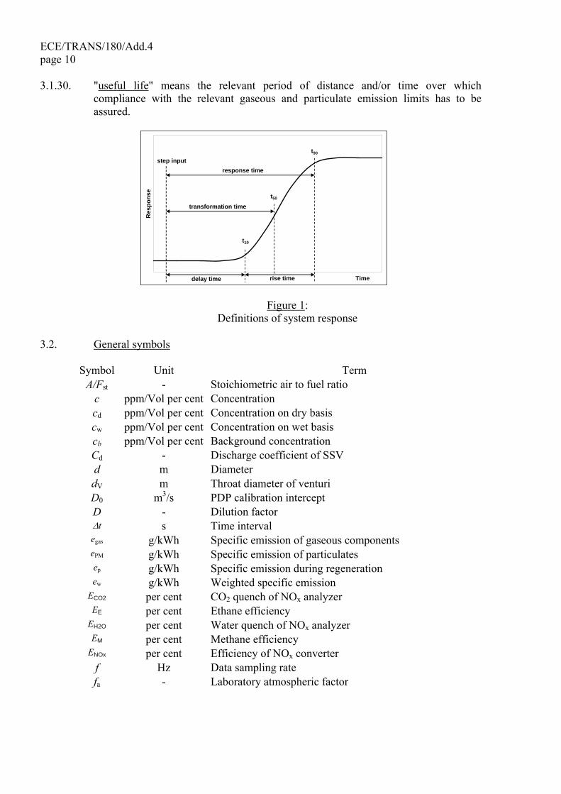
ECE/TRANS/180/Add.4 page 10 3.1.30. "useful life" means the relevant period of distance and/or time over which
compliance with the relevant gaseous and particulate emission limits has to be assured.
Time
Res
pons
e
t10
t50
t90
step inputresponse time
transformation time
delay time rise time
Figure 1: Definitions of system response
3.2. General symbols
Symbol Unit Term A/Fst - Stoichiometric air to fuel ratio
c ppm/Vol per cent Concentration cd ppm/Vol per cent Concentration on dry basis cw ppm/Vol per cent Concentration on wet basis cb ppm/Vol per cent Background concentration Cd - Discharge coefficient of SSV d m Diameter dV m Throat diameter of venturi D0 m3/s PDP calibration intercept D - Dilution factor Δt s Time interval egas g/kWh Specific emission of gaseous components ePM g/kWh Specific emission of particulates ep g/kWh Specific emission during regeneration ew g/kWh Weighted specific emission
ECO2 per cent CO2 quench of NOx analyzer EE per cent Ethane efficiency
EH2O per cent Water quench of NOx analyzer EM per cent Methane efficiency
ENOx per cent Efficiency of NOx converter f Hz Data sampling rate fa - Laboratory atmospheric factor
ECE/TRANS/180/Add.4 page 11
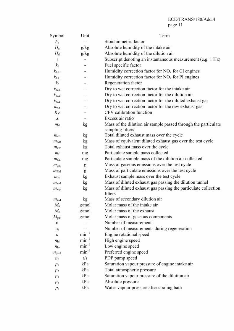
Symbol Unit Term Fs - Stoichiometric factor Ha g/kg Absolute humidity of the intake air Hd g/kg Absolute humidity of the dilution air i - Subscript denoting an instantaneous measurement (e.g. 1 Hz) kf - Fuel specific factor
kh,D - Humidity correction factor for NOx for CI engines kh,G - Humidity correction factor for NOx for PI engines kr - Regeneration factor
kw,a - Dry to wet correction factor for the intake air kw,d - Dry to wet correction factor for the dilution air kw,e - Dry to wet correction factor for the diluted exhaust gas kw,r - Dry to wet correction factor for the raw exhaust gas KV - CFV calibration function λ - Excess air ratio
md kg Mass of the dilution air sample passed through the particulate sampling filters
med kg Total diluted exhaust mass over the cycle medf kg Mass of equivalent diluted exhaust gas over the test cycle mew kg Total exhaust mass over the cycle mf mg Particulate sample mass collected mf,d mg Particulate sample mass of the dilution air collected mgas g Mass of gaseous emissions over the test cycle mPM g Mass of particulate emissions over the test cycle mse kg Exhaust sample mass over the test cycle msed kg Mass of diluted exhaust gas passing the dilution tunnel msep kg Mass of diluted exhaust gas passing the particulate collection
filters mssd kg Mass of secondary dilution air Ma g/mol Molar mass of the intake air Me g/mol Molar mass of the exhaust
Mgas g/mol Molar mass of gaseous components n - Number of measurements nr - Number of measurements during regeneration n min-1 Engine rotational speed
nhi min-1 High engine speed nlo min-1 Low engine speed
npref min-1 Preferred engine speed np r/s PDP pump speed pa kPa Saturation vapour pressure of engine intake air pb kPa Total atmospheric pressure pd kPa Saturation vapour pressure of the dilution air pp kPa Absolute pressure pr kPa Water vapour pressure after cooling bath
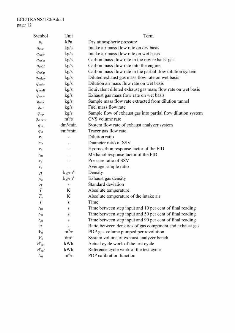
ECE/TRANS/180/Add.4 page 12
Symbol Unit Term ps kPa Dry atmospheric pressure
qmad kg/s Intake air mass flow rate on dry basis qmaw kg/s Intake air mass flow rate on wet basis qmCe kg/s Carbon mass flow rate in the raw exhaust gas qmCf kg/s Carbon mass flow rate into the engine qmCp kg/s Carbon mass flow rate in the partial flow dilution system qmdew kg/s Diluted exhaust gas mass flow rate on wet basis qmdw kg/s Dilution air mass flow rate on wet basis qmedf kg/s Equivalent diluted exhaust gas mass flow rate on wet basis qmew kg/s Exhaust gas mass flow rate on wet basis qmex kg/s Sample mass flow rate extracted from dilution tunnel qmf kg/s Fuel mass flow rate qmp kg/s Sample flow of exhaust gas into partial flow dilution system
qvCVS m³/s CVS volume rate qvs dm³/min System flow rate of exhaust analyzer system qvt cm³/min Tracer gas flow rate rd - Dilution ratio rD - Diameter ratio of SSV rh - Hydrocarbon response factor of the FID rm - Methanol response factor of the FID rp - Pressure ratio of SSV rs - Average sample ratio ρ kg/m³ Density ρe kg/m³ Exhaust gas density σ - Standard deviation T K Absolute temperature Ta K Absolute temperature of the intake air t s Time
t10 s Time between step input and 10 per cent of final reading t50 s Time between step input and 50 per cent of final reading t90 s Time between step input and 90 per cent of final reading u - Ratio between densities of gas component and exhaust gas V0 m3/r PDP gas volume pumped per revolution Vs dm³ System volume of exhaust analyzer bench
Wact kWh Actual cycle work of the test cycle Wref kWh Reference cycle work of the test cycle X0 m3/r PDP calibration function
ECE/TRANS/180/Add.4 page 13
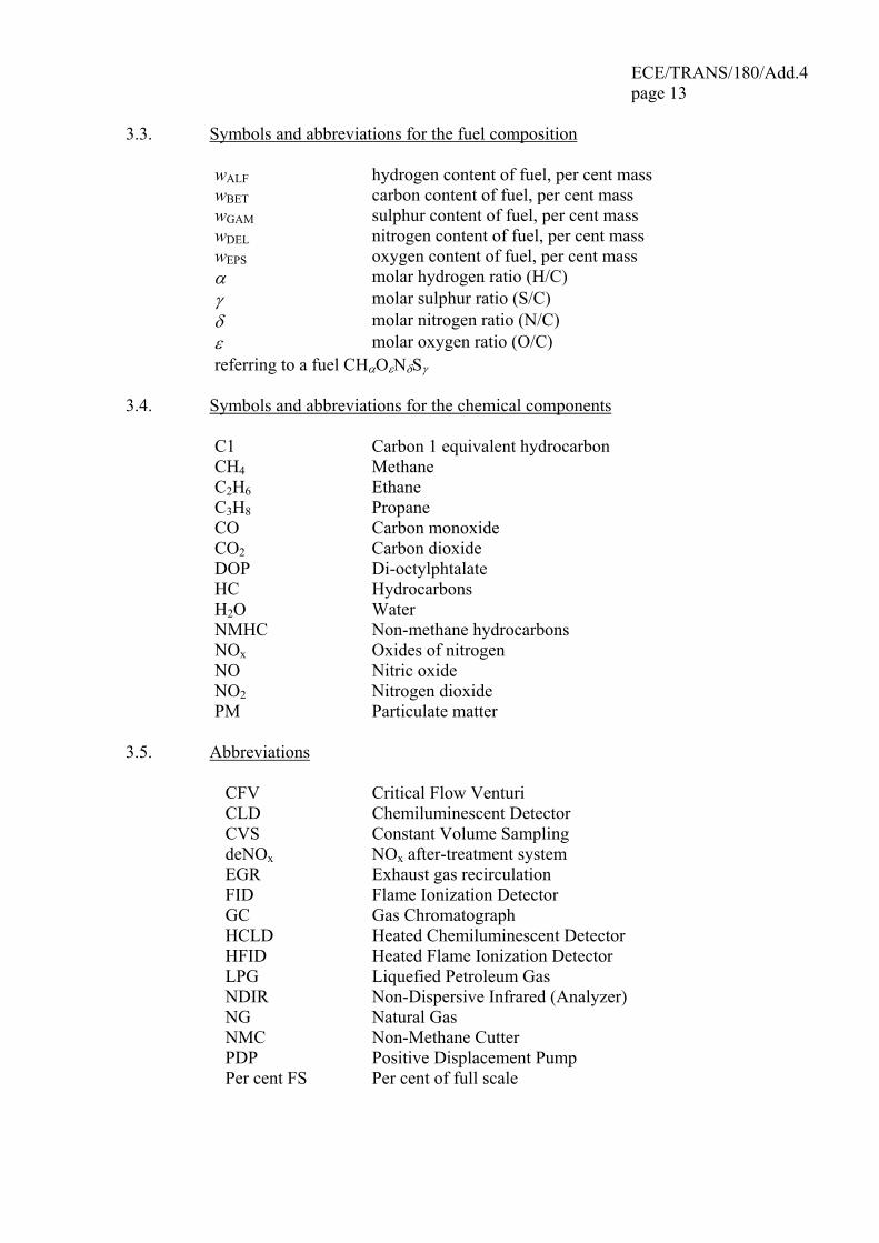
3.3. Symbols and abbreviations for the fuel composition
wALF hydrogen content of fuel, per cent mass wBET carbon content of fuel, per cent mass wGAM sulphur content of fuel, per cent mass wDEL nitrogen content of fuel, per cent mass wEPS oxygen content of fuel, per cent mass α molar hydrogen ratio (H/C) γ molar sulphur ratio (S/C) δ molar nitrogen ratio (N/C) ε molar oxygen ratio (O/C) referring to a fuel CHαOεNδSγ
3.4. Symbols and abbreviations for the chemical components
C1 Carbon 1 equivalent hydrocarbon CH4 Methane C2H6 Ethane C3H8 Propane CO Carbon monoxide CO2 Carbon dioxide DOP Di-octylphtalate HC Hydrocarbons H2O Water NMHC Non-methane hydrocarbons NOx Oxides of nitrogen NO Nitric oxide NO2 Nitrogen dioxide PM Particulate matter
3.5. Abbreviations
CFV Critical Flow Venturi CLD Chemiluminescent Detector CVS Constant Volume Sampling deNOx NOx after-treatment system EGR Exhaust gas recirculation FID Flame Ionization Detector GC Gas Chromatograph HCLD Heated Chemiluminescent Detector HFID Heated Flame Ionization Detector LPG Liquefied Petroleum Gas NDIR Non-Dispersive Infrared (Analyzer) NG Natural Gas NMC Non-Methane Cutter PDP Positive Displacement Pump Per cent FS Per cent of full scale
ECE/TRANS/180/Add.4 page 14
PFS Partial Flow System SSV Subsonic Venturi VGT Variable Geometry Turbine
4. GENERAL REQUIREMENTS The engine system shall be so designed, constructed and assembled as to enable the
engine in normal use to comply with the provisions of this gtr during its useful life, as defined by the Contracting Party, including when installed in the vehicle.
5. PERFORMANCE REQUIREMENTS When implementing the test procedure contained in this gtr as part of their national
legislation, Contracting Parties to the 1998 Agreement are encouraged to use limit values which represent at least the same level of severity as their existing regulations; pending the development of harmonized limit values, by the Executive Committee (AC.3) of the 1998 Agreement, for inclusion in the gtr at a later date.
5.1. Emission of gaseous and particulate pollutants The emissions of gaseous and particulate pollutants by the engine shall be
determined on the WHTC and WHSC test cycles, as described in paragraph 7. The measurement systems shall meet the linearity requirements in paragraph 9.2. and the specifications in paragraph 9.3. (gaseous emissions measurement), paragraph 9.4. (particulate measurement) and in Annex 3.
Other systems or analyzers may be approved by the type approval or certification
authority, if it is found that they yield equivalent results in accordance with paragraph 5.1.1.
5.1.1. Equivalency The determination of system equivalency shall be based on a seven-sample pair (or
larger) correlation study between the system under consideration and one of the systems of this gtr.
"Results" refer to the specific cycle weighted emissions value. The correlation
testing is to be performed at the same laboratory, test cell, and on the same engine, and is preferred to be run concurrently. The equivalency of the sample pair averages shall be determined by F-test and t-test statistics as described in Annex 4 obtained under the laboratory test cell and the engine conditions described above. Outliers shall be determined in accordance with ISO 5725 and excluded from the database. The systems to be used for correlation testing shall be subject to the approval by the type approval or certification authority.

ECE/TRANS/180/Add.4 page 15
5.2. Engine family 5.2.1. General An engine family is characterized by design parameters. These shall be common to
all engines within the family. The engine manufacturer may decide, which engines belong to an engine family, as long as the membership criteria listed in paragraph 5.2.3. are respected. The engine family shall be approved by the type approval or certification authority. The manufacturer shall provide to the type approval or certification authority the appropriate information relating to the emission levels of the members of the engine family.
5.2.2. Special cases In some cases there may be interaction between parameters. This shall be taken into
consideration to ensure that only engines with similar exhaust emission characteristics are included within the same engine family. These cases shall be identified by the manufacturer and notified to the type approval or certification authority. It shall then be taken into account as a criterion for creating a new engine family.
In case of devices or features, which are not listed in paragraph 5.2.3. and which
have a strong influence on the level of emissions, this equipment shall be identified by the manufacturer on the basis of good engineering practice, and shall be notified to the type approval or certification authority. It shall then be taken into account as a criterion for creating a new engine family.
In addition to the parameters listed in paragraph 5.2.3., the manufacturer may
introduce additional criteria allowing the definition of families of more restricted size. These parameters are not necessarily parameters that have an influence on the level of emissions.
5.2.3. Parameters defining the engine family 5.2.3.1. Combustion cycle (a) 2-stroke cycle (b) 4-stroke cycle (c) Rotary engine (d) Others 5.2.3.2. Configuration of the cylinders 5.2.3.2.1. Position of the cylinders in the block (a) V (b) In line (c) Radial (d) Others (F, W, etc.)
ECE/TRANS/180/Add.4 page 16 5.2.3.2.2. Relative position of the cylinders Engines with the same block may belong to the same family as long as their bore
center-to-center dimensions are the same. 5.2.3.3. Main cooling medium (a) air (b) water (c) oil 5.2.3.4. Individual cylinder displacement 5.2.3.4.1. Engine with a unit cylinder displacement ≥ 0.75 dm³ In order for engines with a unit cylinder displacement of ≥ 0.75 dm³ to be
considered to belong to the same engine family, the spread of their individual cylinder displacements shall not exceed 15 per cent of the largest individual cylinder displacement within the family.
5.2.3.4.2. Engine with a unit cylinder displacement < 0.75 dm³ In order for engines with a unit cylinder displacement of < 0.75 dm³ to be
considered to belong to the same engine family, the spread of their individual cylinder displacements shall not exceed 30 per cent of the largest individual cylinder displacement within the family.
5.2.3.4.3. Engine with other unit cylinder displacement limits Engines with an individual cylinder displacement that exceeds the limits defined in
paragraphs 5.2.3.4.1. and 5.2.3.4.2. may be considered to belong to the same family with the approval of the type approval or certification authority. The approval shall be based on technical elements (calculations, simulations, experimental results etc.) showing that exceeding the limits does not have a significant influence on the exhaust emissions.
5.2.3.5. Method of air aspiration (a) naturally aspirated (b) pressure charged (c) pressure charged with charge cooler 5.2.3.6. Fuel type (a) Diesel (b) Natural gas (NG) (c) Liquefied petroleum gas (LPG) (d) Ethanol
ECE/TRANS/180/Add.4 page 17
5.2.3.7. Combustion chamber type (a) Open chamber (b) Divided chamber (c) Other types 5.2.3.8. Ignition Type (a) Positive ignition (b) Compression ignition 5.2.3.9. Valves and porting (a) Configuration (b) Number of valves per cylinder 5.2.3.10. Fuel supply type (a) Liquid fuel supply type (i)Pump and (high pressure) line and injector (ii)In-line or distributor pump (iii)Unit pump or unit injector (iv)Common rail (v)Carburettor(s) (vi)Others (b) Gas fuel supply type (i)Gaseous (ii)Liquid (iii)Mixing units (iv)Others (c) Other types 5.2.3.11. Miscellaneous devices (a) Exhaust gas recirculation (EGR) (b) Water injection (c) Air injection (d) Others 5.2.3.12. Electronic control strategy The presence or absence of an electronic control unit (ECU) on the engine is
regarded as a basic parameter of the family. In the case of electronically controlled engines, the manufacturer shall present the
technical elements explaining the grouping of these engines in the same family, i.e. the reasons why these engines can be expected to satisfy the same emission requirements.
These elements can be calculations, simulations, estimations, description of injection parameters, experimental results, etc.
Examples of controlled features are:
ECE/TRANS/180/Add.4 page 18 (a) Timing (b) Injection pressure (c) Multiple injections (d) Boost pressure (e) VGT (f) EGR 5.2.3.13. Exhaust after-treatment systems The function and combination of the following devices are regarded as membership
criteria for an engine family: (a) Oxidation catalyst (b) Three-way catalyst (c) DeNOx system with selective reduction of NOx (addition of reducing agent) (d) Other DeNOx systems (e) Particulate trap with passive regeneration (f) Particulate trap with active regeneration (g) Other particulate traps (h) Other devices When an engine has been certified without after-treatment system, whether as parent
engine or as member of the family, then this engine, when equipped with an oxidation catalyst, may be included in the same engine family, if it does not require different fuel characteristics.
If it requires specific fuel characteristics (e.g. particulate traps requiring special
additives in the fuel to ensure the regeneration process), the decision to include it in the same family shall be based on technical elements provided by the manufacturer. These elements shall indicate that the expected emission level of the equipped engine complies with the same limit value as the non-equipped engine.
When an engine has been certified with after-treatment system, whether as parent
engine or as member of a family, whose parent engine is equipped with the same after-treatment system, then this engine, when equipped without after-treatment system, must not be added to the same engine family.
5.2.4. Choice of the parent engine 5.2.4.1. Compression ignition engines Once the engine family has been agreed by the type approval or certification
authority, the parent engine of the family shall be selected using the primary criterion of the highest fuel delivery per stroke at the declared maximum torque speed. In the event that two or more engines share this primary criterion, the parent engine shall be selected using the secondary criterion of highest fuel delivery per stroke at rated speed.
ECE/TRANS/180/Add.4 page 19
5.2.4.2. Positive ignition engines Once the engine family has been agreed by the type approval or certification
authority, the parent engine of the family shall be selected using the primary criterion of the largest displacement. In the event that two or more engines share this primary criterion, the parent engine shall be selected using the secondary criterion in the following order of priority:
(a) the highest fuel delivery per stroke at the speed of declared rated power; (b) the most advanced spark timing; (c) the lowest EGR rate. 5.2.4.3. Remarks on the choice of the parent engine The type approval or certification authority may conclude that the worst-case
emission of the family can best be characterized by testing additional engines. In this case, the engine manufacturer shall submit the appropriate information to determine the engines within the family likely to have the highest emissions level.
If engines within the family incorporate other features which may be considered to
affect exhaust emissions, these features shall also be identified and taken into account in the selection of the parent engine.
If engines within the family meet the same emission values over different useful life
periods, this shall be taken into account in the selection of the parent engine. 6. TEST CONDITIONS 6.1. Laboratory test conditions The absolute temperature (Ta) of the engine intake air expressed in Kelvin, and the
dry atmospheric pressure (ps), expressed in kPa shall be measured and the parameter fa shall be determined according to the following provisions. In multi-cylinder engines having distinct groups of intake manifolds, such as in a "Vee" engine configuration, the average temperature of the distinct groups shall be taken. The parameter fa shall be reported with the test results. For better repeatability and reproducibility of the test results, it is recommended that the parameter fa be such that: 0.93 ≤ fa ≤ 1.07. Contracting Parties can make the parameter fa compulsory.
(a)Compression-ignition engines: Naturally aspirated and mechanically supercharged engines:
0.7
a
s 29899
a ⎟⎟⎠
⎞⎜⎜⎝
⎛⎟⎟⎠
⎞⎜⎜⎝
⎛×=
Tp
f (1)
ECE/TRANS/180/Add.4 page 20 Turbocharged engines with or without cooling of the intake air:
1.5
a0.7
s 29899
a ⎟⎟⎠
⎞⎜⎜⎝
⎛⎟⎟⎠
⎞⎜⎜⎝
⎛×=
Tp
f (2)
(b)Positive ignition engines:
0.6
a1.2
s 29899
a ⎟⎟⎠
⎞⎜⎜⎝
⎛⎟⎟⎠
⎞⎜⎜⎝
⎛×=
Tp
f (3)
6.2. Engines with charge air-cooling The charge air temperature shall be recorded and shall be, at the rated speed and full
load, within ± 5 K of the maximum charge air temperature specified by the manufacturer. The temperature of the cooling medium shall be at least 293 K (20 °C).
If a test laboratory system or external blower is used, the charge air temperature shall
be set to within ± 5 K of the maximum charge air temperature specified by the manufacturer at the rated speed and full load. Coolant temperature and coolant flow rate of the charge air cooler at the above set point shall not be changed for the whole test cycle, unless this results in unrepresentative overcooling of the charge air. The charge air cooler volume shall be based upon good engineering practice and shall be representative of the production engine's in-use installation.
6.3. Engine power The basis of specific emissions measurement is uncorrected power as defined by the
Contracting Parties. Certain auxiliaries, which are only necessary only for the operation of the vehicle
and which may be mounted on the engine should be removed for the test. The following incomplete list is given as an example:
(a) air compressor for brakes (b) power steering compressor (c) air conditioning compressor (d) pumps for hydraulic actuators Where auxiliaries have not been removed, the power absorbed by them shall be
determined in order to adjust the set values and to calculate the work produced by the engine over the test cycle.
ECE/TRANS/180/Add.4 page 21
6.4. Engine air intake system An engine air intake system or a test laboratory system shall be used presenting an
air intake restriction within ± 300 Pa of the maximum value specified by the manufacturer for a clean air cleaner at the rated speed and full load.
6.5. Engine exhaust system An engine exhaust system or a test laboratory system shall be used presenting an
exhaust backpressure within ± 650 Pa of the maximum value specified by the manufacturer at the rated speed and full load. The exhaust system shall conform to the requirements for exhaust gas sampling, as set out in paragraphs 8.3.2.2. and 8.3.3.2.
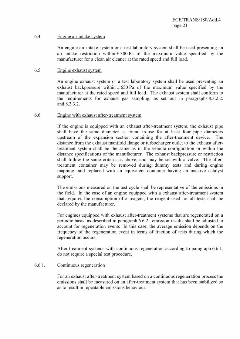
6.6. Engine with exhaust after-treatment system If the engine is equipped with an exhaust after-treatment system, the exhaust pipe
shall have the same diameter as found in-use for at least four pipe diameters upstream of the expansion section containing the after-treatment device. The distance from the exhaust manifold flange or turbocharger outlet to the exhaust after-treatment system shall be the same as in the vehicle configuration or within the distance specifications of the manufacturer. The exhaust backpressure or restriction shall follow the same criteria as above, and may be set with a valve. The after-treatment container may be removed during dummy tests and during engine mapping, and replaced with an equivalent container having an inactive catalyst support.
The emissions measured on the test cycle shall be representative of the emissions in
the field. In the case of an engine equipped with a exhaust after-treatment system that requires the consumption of a reagent, the reagent used for all tests shall be declared by the manufacturer.
For engines equipped with exhaust after-treatment systems that are regenerated on a
periodic basis, as described in paragraph 6.6.2., emission results shall be adjusted to account for regeneration events In this case, the average emission depends on the frequency of the regeneration event in terms of fraction of tests during which the regeneration occurs.
After-treatment systems with continuous regeneration according to paragraph 6.6.1.
do not require a special test procedure. 6.6.1. Continuous regeneration For an exhaust after-treatment system based on a continuous regeneration process the
emissions shall be measured on an after-treatment system that has been stabilized so as to result in repeatable emissions behaviour.
ECE/TRANS/180/Add.4 page 22 The regeneration process shall occur at least once during the WHTC test and the
manufacturer shall declare the normal conditions under which regeneration occurs (soot load, temperature, exhaust back-pressure, etc.).
In order to demonstrate that the regeneration process is continuous, at least three
WHTC hot start tests shall be conducted. During the tests, exhaust temperatures and pressures shall be recorded (temperature before and after the after-treatment system, exhaust back pressure, etc.).
The after-treatment system is considered to be satisfactory if the conditions declared
by the manufacturer occur during the test during a sufficient time and the emission results do not scatter by more than ±15 per cent.
If the exhaust after-treatment system has a security mode that shifts to a periodic
regeneration mode, it shall be checked according to paragraph 6.6.2. For that specific case, the applicable emission limits may be exceeded and would not be weighted.
6.6.2. Periodic regeneration For an exhaust after-treatment based on a periodic regeneration process, the
emissions shall be measured on at least three WHTC tests, one during and two outside a regeneration event on a stabilized after-treatment system, and the results be weighted.
The regeneration process shall occur at least once during the WHTC test. The engine
may be equipped with a switch capable of preventing or permitting the regeneration process provided this operation has no effect on the original engine calibration.
The manufacturer shall declare the normal parameter conditions under which the regeneration process occurs (soot load, temperature, exhaust back-pressure, etc.) and its duration based on the number of cycles (nr). The manufacturer shall also provide all the data to determine the number of cycles between two regenerations (n). The exact procedure to determine this time shall be agreed by the type approval or certification authority based upon good engineering judgement.
The manufacturer shall provide an after-treatment system that has been loaded in
order to achieve regeneration during a WHTC test. Regeneration shall not occur during this engine-conditioning phase.
Average emissions between regeneration phases shall be determined from the
arithmetic mean of several approximately equidistant WHTC hot start tests. As a minimum, at least one WHTC as close as possible prior to a regeneration test and one WHTC immediately after a regeneration test shall be conducted. As an alternative, the manufacturer may provide data to show that the emissions remain constant (± 15 per cent) between regeneration phases. In this case, the emissions of only one WHTC test may be used.
ECE/TRANS/180/Add.4 page 23
During the regeneration test, all the data needed to detect regeneration shall be
recorded (CO or NOx emissions, temperature before and after the after-treatment system, exhaust back pressure, etc.).
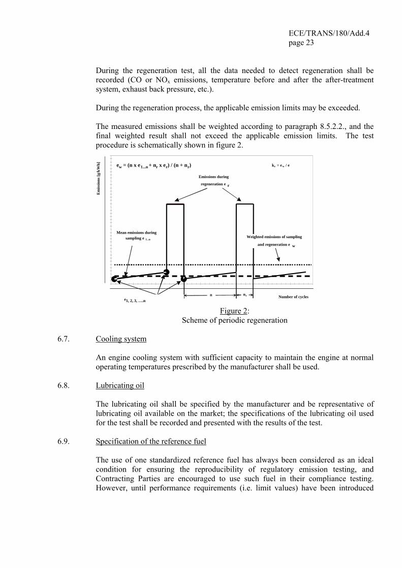
During the regeneration process, the applicable emission limits may be exceeded. The measured emissions shall be weighted according to paragraph 8.5.2.2., and the
final weighted result shall not exceed the applicable emission limits. The test procedure is schematically shown in figure 2.
0
0,2
0,4
0,6
0,8
1
1,2
1,4
1,6
0 0,5 1 1,5 2 2,5 3 3,5 4 4,5 Number of cycles
Em
issi
ons [
g/kW
h]
n nr
Mean emissions during sampling e 1...n
e 1, 2, 3, ….n
Emissions during
regeneration e r
ew = (n x e 1...n + n r x e r) / (n + nr)
Weighted emissions of sampling and regeneration e w
kr = e w / e
Figure 2:
Scheme of periodic regeneration 6.7. Cooling system An engine cooling system with sufficient capacity to maintain the engine at normal
operating temperatures prescribed by the manufacturer shall be used. 6.8. Lubricating oil The lubricating oil shall be specified by the manufacturer and be representative of
lubricating oil available on the market; the specifications of the lubricating oil used for the test shall be recorded and presented with the results of the test.
6.9. Specification of the reference fuel The use of one standardized reference fuel has always been considered as an ideal
condition for ensuring the reproducibility of regulatory emission testing, and Contracting Parties are encouraged to use such fuel in their compliance testing. However, until performance requirements (i.e. limit values) have been introduced

ECE/TRANS/180/Add.4 page 24
into this gtr, Contracting Parties to the 1998 Agreement are allowed to define their own reference fuel for their national legislation, to address the actual situation of market fuel for vehicles in use.
The appropriate diesel reference fuels of the European Union, the United States of
America and Japan listed in Annex 2 are recommended to be used for testing. Since fuel characteristics influence the engine exhaust gas emission, the characteristics of the fuel used for the test shall be determined, recorded and declared with the results of the test.
No CNG and LPG reference fuels are listed due to the significant differences in local fuel qualities.
The fuel temperature shall be in accordance with the manufacturers recommendations.
7. TEST PROCEDURES 7.1. Principles of emissions measurement In this gtr, two measurement principles are described that are functionally equivalent.
Both principles may be used for both the WHTC and the WHSC test cycle: (a) the gaseous components are measured in the raw exhaust gas on a real time
basis, and the particulates are determined using a partial flow dilution system; (b) the gaseous components and the particulates are determined using a full flow
dilution system (CVS system); (c) any combination of the two principles (e.g. raw gaseous measurement and full
flow particulate measurement) is permitted. The engine shall be subjected to the test cycles specified below. 7.2. Transient test cycle WHTC The transient test cycle WHTC is listed in Annex 1 as a second-by-second sequence
of normalized speed and torque values applicable to all engines covered by this gtr. In order to perform the test on an engine test cell, the normalized values shall be converted to the actual values for the individual engine under test based on the engine-mapping curve. The conversion is referred to as denormalization, and the test cycle so developed as the reference cycle of the engine to be tested. With those reference speed and torque values, the cycle shall be run on the test cell, and the actual speed, torque and power values shall be recorded. In order to validate the test run, a regression analysis between reference and actual speed, torque and power values shall be conducted upon completion of the test.
For calculation of the brake specific emissions, the actual cycle work shall be
calculated by integrating actual engine power over the cycle. For cycle validation,
ECE/TRANS/180/Add.4 page 25
the actual cycle work must be within prescribed limits of the cycle work of the reference cycle (reference cycle work).
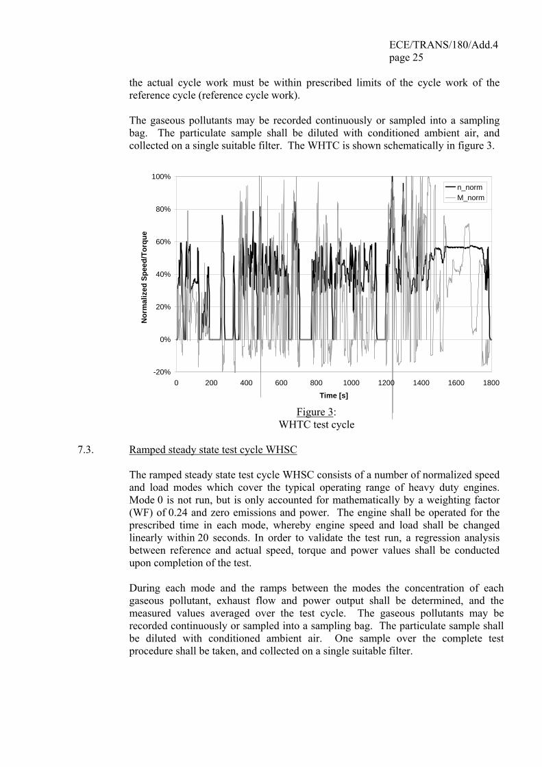
The gaseous pollutants may be recorded continuously or sampled into a sampling
bag. The particulate sample shall be diluted with conditioned ambient air, and collected on a single suitable filter. The WHTC is shown schematically in figure 3.
-20%
0%
20%
40%
60%
80%
100%
0 200 400 600 800 1000 1200 1400 1600 1800
Time [s]
Nor
mal
ized
Spe
ed/T
orqu
e
n_normM_norm
Figure 3:
WHTC test cycle 7.3. Ramped steady state test cycle WHSC The ramped steady state test cycle WHSC consists of a number of normalized speed
and load modes which cover the typical operating range of heavy duty engines. Mode 0 is not run, but is only accounted for mathematically by a weighting factor (WF) of 0.24 and zero emissions and power. The engine shall be operated for the prescribed time in each mode, whereby engine speed and load shall be changed linearly within 20 seconds. In order to validate the test run, a regression analysis between reference and actual speed, torque and power values shall be conducted upon completion of the test.
During each mode and the ramps between the modes the concentration of each
gaseous pollutant, exhaust flow and power output shall be determined, and the measured values averaged over the test cycle. The gaseous pollutants may be recorded continuously or sampled into a sampling bag. The particulate sample shall be diluted with conditioned ambient air. One sample over the complete test procedure shall be taken, and collected on a single suitable filter.
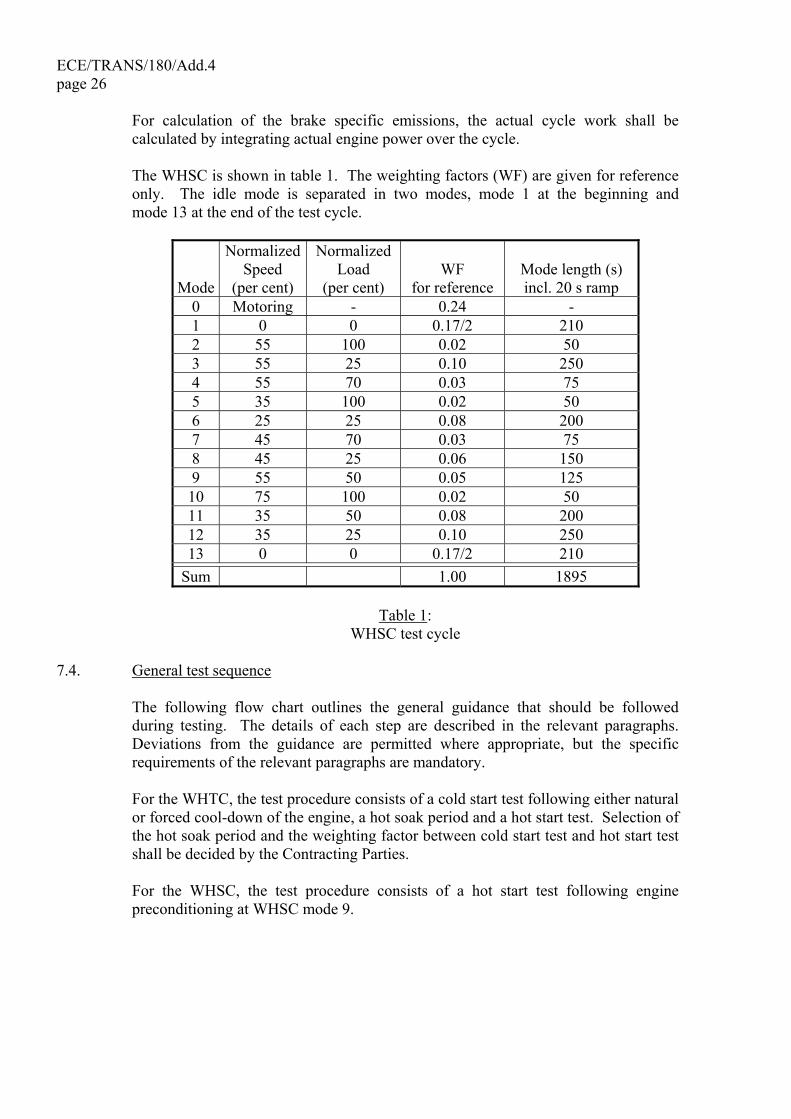
ECE/TRANS/180/Add.4 page 26 For calculation of the brake specific emissions, the actual cycle work shall be
calculated by integrating actual engine power over the cycle. The WHSC is shown in table 1. The weighting factors (WF) are given for reference
only. The idle mode is separated in two modes, mode 1 at the beginning and mode 13 at the end of the test cycle.
Mode
Normalized Speed
(per cent)
Normalized Load
(per cent) WF
for reference Mode length (s) incl. 20 s ramp
0 Motoring - 0.24 - 1 0 0 0.17/2 210 2 55 100 0.02 50 3 55 25 0.10 250 4 55 70 0.03 75 5 35 100 0.02 50 6 25 25 0.08 200 7 45 70 0.03 75 8 45 25 0.06 150 9 55 50 0.05 125 10 75 100 0.02 50 11 35 50 0.08 200 12 35 25 0.10 250 13 0 0 0.17/2 210
Sum 1.00 1895
Table 1: WHSC test cycle
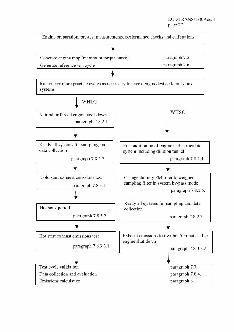
7.4. General test sequence The following flow chart outlines the general guidance that should be followed
during testing. The details of each step are described in the relevant paragraphs. Deviations from the guidance are permitted where appropriate, but the specific requirements of the relevant paragraphs are mandatory.
For the WHTC, the test procedure consists of a cold start test following either natural
or forced cool-down of the engine, a hot soak period and a hot start test. Selection of the hot soak period and the weighting factor between cold start test and hot start test shall be decided by the Contracting Parties.
For the WHSC, the test procedure consists of a hot start test following engine
preconditioning at WHSC mode 9.
ECE/TRANS/180/Add.4 page 27
Engine preparation, pre-test measurements, performance checks and calibrations
Generate engine map (maximum torque curve) paragraph 7.5.
Generate reference test cycle paragraph 7.6.
Run one or more practice cycles as necessary to check engine/test cell/emissions systems
WHSC Natural or forced engine cool-down paragraph 7.8.2.1.
Ready all systems for sampling anddata collection
paragraph 7.8.2.7.
Preconditioning of engine and particulate system including dilution tunnel
paragraph 7.8.2.4.
Cold start exhaust emissions test
paragraph 7.8.3.1.
Change dummy PM filter to weighed sampling filter in system by-pass mode
paragraph 7.8.2.5.
Ready all systems for sampling and data collection
paragraph 7.8.2.7.
Hot soak period
paragraph 7.8.3.2.
Hot start exhaust emissions test
paragraph 7.8.3.3.1.
Exhaust emissions test within 5 minutes after engine shut down
paragraph 7.8.3.3.2.
Data collection and evaluation paragraph 7.8.4. Emissions calculation paragraph 8.
WHTC
Test cycle validation paragraph 7.7.
ECE/TRANS/180/Add.4 page 28 7.5. Engine mapping procedure For generating the WHTC and WHSC on the test cell, the engine shall be mapped
prior to the run of the test cycle for determining the speed vs. torque and speed vs. power curves.
7.5.1. Determination of the mapping speed range The minimum and maximum mapping speeds are defined as follows: Minimum mapping speed = idle speed Maximum mapping speed = nhi x 1.02 or speed where full load torque drops
off to zero, whichever is smaller. 7.5.2. Engine mapping curve The engine shall be warmed up at maximum power in order to stabilize the engine
parameters according to the recommendation of the manufacturer and good engineering practice. When the engine is stabilized, the engine mapping shall be performed according to the following procedure.
(a) The engine shall be unloaded and operated at idle speed. (b) The engine shall be operated at full load setting of the injection pump at
minimum mapping speed. (c) The engine speed shall be increased at an average rate of 8 ± 1 min-1/s from
minimum to maximum mapping speed. Engine speed and torque points shall be recorded at a sample rate of at least one point per second.
7.5.3. Alternate mapping If a manufacturer believes that the above mapping techniques are unsafe or
unrepresentative for any given engine, alternate mapping techniques may be used. These alternate techniques must satisfy the intent of the specified mapping procedures to determine the maximum available torque at all engine speeds achieved during the test cycles. Deviations from the mapping techniques specified in this paragraph for reasons of safety or representativeness shall be approved by the type approval or certification authority along with the justification for their use. In no case, however, the torque curve shall be run by descending engine speeds for governed or turbocharged engines.
7.5.4. Replicate tests An engine need not be mapped before each and every test cycle. An engine shall be
remapped prior to a test cycle if: (a) an unreasonable amount of time has transpired since the last map, as
determined by engineering judgement, or (b) physical changes or recalibrations have been made to the engine which
potentially affect engine performance.
ECE/TRANS/180/Add.4 page 29
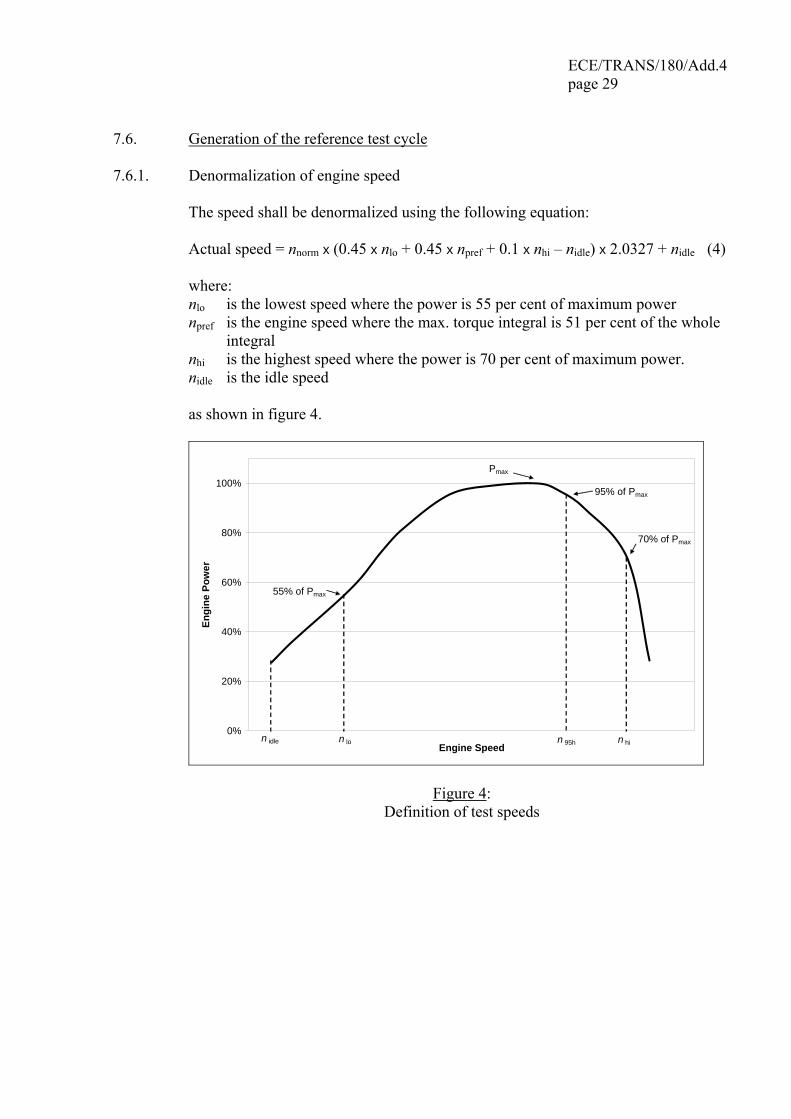
7.6. Generation of the reference test cycle 7.6.1. Denormalization of engine speed The speed shall be denormalized using the following equation: Actual speed = nnorm x (0.45 x nlo + 0.45 x npref + 0.1 x nhi – nidle) x 2.0327 + nidle (4) where: nlo is the lowest speed where the power is 55 per cent of maximum power npref is the engine speed where the max. torque integral is 51 per cent of the whole
integral nhi is the highest speed where the power is 70 per cent of maximum power. nidle is the idle speed as shown in figure 4.
0%
20%
40%
60%
80%
100%
Engine Speed
Engi
ne P
ower
Pmax
55% of Pmax
95% of Pmax
70% of Pmax
n idle n lo n 95h n hi
Figure 4: Definition of test speeds

ECE/TRANS/180/Add.4 page 30 7.6.1.1. Determination of preferred speed From the engine mapping curve as determined in accordance with paragraph 7.5.2.,
the integral of the maximum torque shall be calculated from nidle to n95h. n95h is the highest speed where the power is 95 per cent of maximum power. npref is then defined as the speed that corresponds to 51 per cent of the whole integral, as shown in figure 5.
60,0%
80,0%
100,0%
Engine Speed
Engi
ne T
orqu
e
n idle n 95hn pref
Area = 100 %Area = 51 %
Figure 5: Definition of npref
7.6.2. Denormalization of engine torque The torque values in the engine dynamometer schedule of Annex 1 are normalized to
the maximum torque at the respective speed. The torque values of the reference cycle shall be denormalized, using the mapping curve determined according to paragraph 7.5.2., as follows:
Actual torque = 100
torquemax.ecent torquper × (5)
for the respective actual speed as determined in paragraph 7.6.1. 7.6.3. Example of denormalization procedure As an example, the following test point shall be denormalized: per cent speed=43 per cent per cent torque=82 per cent
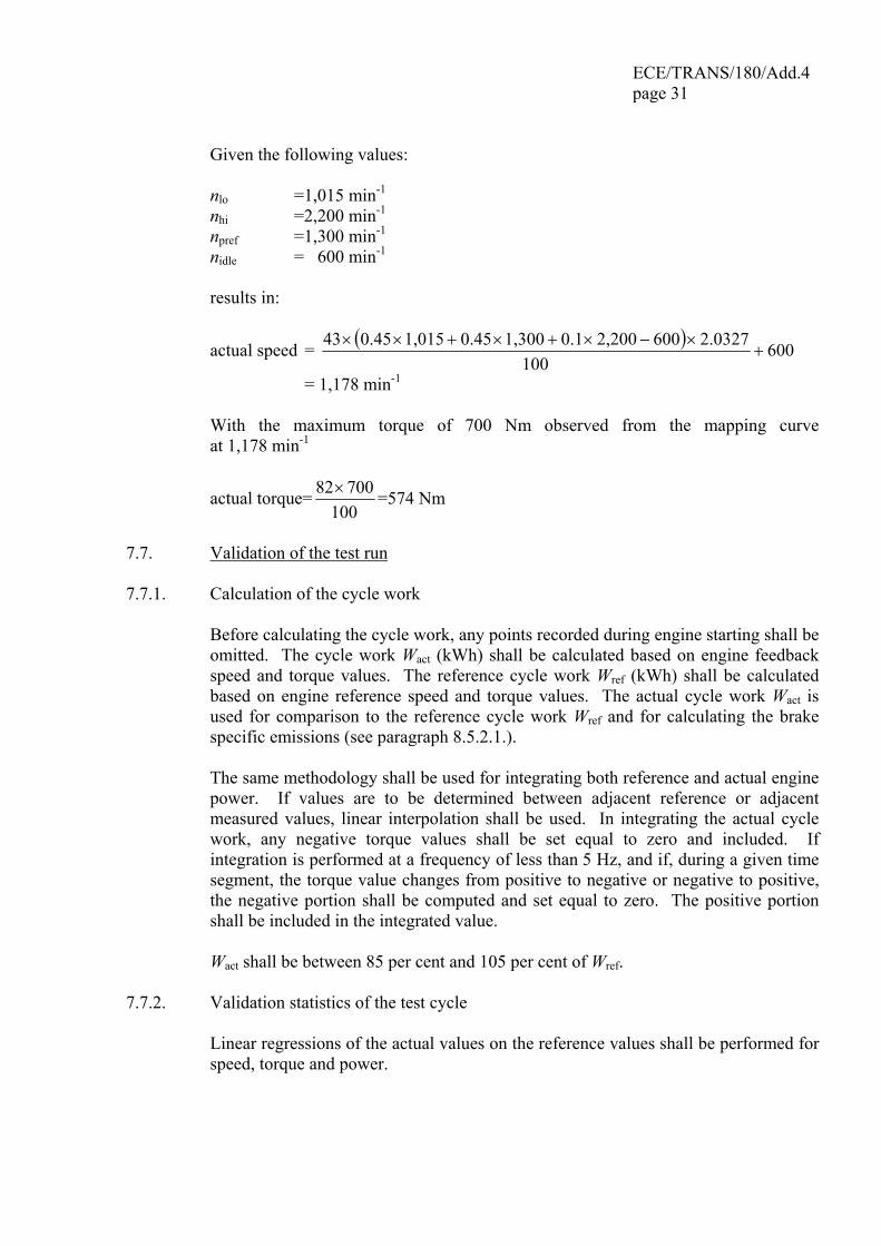
ECE/TRANS/180/Add.4 page 31
Given the following values: nlo =1,015 min-1 nhi =2,200 min-1 npref =1,300 min-1 nidle = 600 min-1 results in:
actual speed = ( ) 600100
2.03276002,2000.11,3000.451,0150.4543+
×−×+×+××
= 1,178 min-1 With the maximum torque of 700 Nm observed from the mapping curve
at 1,178 min-1
actual torque=100
70082× =574 Nm
7.7. Validation of the test run 7.7.1. Calculation of the cycle work Before calculating the cycle work, any points recorded during engine starting shall be
omitted. The cycle work Wact (kWh) shall be calculated based on engine feedback speed and torque values. The reference cycle work Wref (kWh) shall be calculated based on engine reference speed and torque values. The actual cycle work Wact is used for comparison to the reference cycle work Wref and for calculating the brake specific emissions (see paragraph 8.5.2.1.).
The same methodology shall be used for integrating both reference and actual engine
power. If values are to be determined between adjacent reference or adjacent measured values, linear interpolation shall be used. In integrating the actual cycle work, any negative torque values shall be set equal to zero and included. If integration is performed at a frequency of less than 5 Hz, and if, during a given time segment, the torque value changes from positive to negative or negative to positive, the negative portion shall be computed and set equal to zero. The positive portion shall be included in the integrated value.
Wact shall be between 85 per cent and 105 per cent of Wref. 7.7.2. Validation statistics of the test cycle Linear regressions of the actual values on the reference values shall be performed for
speed, torque and power.
ECE/TRANS/180/Add.4 page 32 To minimize the biasing effect of the time lag between the actual and reference cycle
values, the entire engine speed and torque actual signal sequence may be advanced or delayed in time with respect to the reference speed and torque sequence. If the actual signals are shifted, both speed and torque must be shifted the same amount in the same direction.
The method of least squares shall be used, with the best-fit equation having the form: y = mx + b (6) where: y=actual value of speed (min-1), torque (Nm), or power (kW) m=slope of the regression line x=reference value of speed (min-1), torque (Nm), or power (kW) b=y intercept of the regression line The standard error of estimate (SEE) of y on x and the coefficient of determination
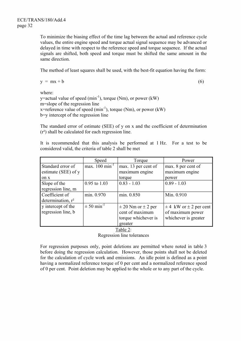
(r²) shall be calculated for each regression line. It is recommended that this analysis be performed at 1 Hz. For a test to be
considered valid, the criteria of table 2 shall be met
Speed Torque Power Standard error of estimate (SEE) of y on x
max. 100 min-1 max. 13 per cent of maximum engine torque
max. 8 per cent of maximum engine power
Slope of the regression line, m
0.95 to 1.03 0.83 - 1.03 0.89 - 1.03
Coefficient of determination, r²
min. 0.970 min. 0.850 Min. 0.910
y intercept of the regression line, b
± 50 min-1 ± 20 Nm or ± 2 per cent of maximum torque whichever is greater
± 4 kW or ± 2 per cent of maximum power whichever is greater
Table 2: Regression line tolerances
For regression purposes only, point deletions are permitted where noted in table 3
before doing the regression calculation. However, those points shall not be deleted for the calculation of cycle work and emissions. An idle point is defined as a point having a normalized reference torque of 0 per cent and a normalized reference speed of 0 per cent. Point deletion may be applied to the whole or to any part of the cycle.
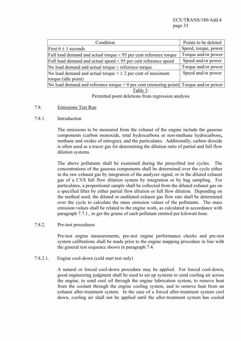
ECE/TRANS/180/Add.4 page 33
Condition Points to be deleted
First 6 ± 1 seconds Speed, torque, powerFull load demand and actual torque < 95 per cent reference torque Torque and/or powerFull load demand and actual speed < 95 per cent reference speed Speed and/or power No load demand and actual torque > reference torque Torque and/or powerNo load demand and actual torque > ± 2 per cent of maximum torque (idle point)
Speed and/or power
No load demand and reference torque < 0 per cent (motoring point) Torque and/or powerTable 3:
Permitted point deletions from regression analysis 7.8. Emissions Test Run 7.8.1. Introduction The emissions to be measured from the exhaust of the engine include the gaseous
components (carbon monoxide, total hydrocarbons or non-methane hydrocarbons, methane and oxides of nitrogen), and the particulates. Additionally, carbon dioxide is often used as a tracer gas for determining the dilution ratio of partial and full flow dilution systems.
The above pollutants shall be examined during the prescribed test cycles. The
concentrations of the gaseous components shall be determined over the cycle either in the raw exhaust gas by integration of the analyzer signal, or in the diluted exhaust gas of a CVS full flow dilution system by integration or by bag sampling. For particulates, a proportional sample shall be collected from the diluted exhaust gas on a specified filter by either partial flow dilution or full flow dilution. Depending on the method used, the diluted or undiluted exhaust gas flow rate shall be determined over the cycle to calculate the mass emission values of the pollutants. The mass emission values shall be related to the engine work, as calculated in accordance with paragraph 7.7.1., to get the grams of each pollutant emitted per kilowatt hour.
7.8.2. Pre-test procedures Pre-test engine measurements, pre-test engine performance checks and pre-test
system calibrations shall be made prior to the engine mapping procedure in line with the general test sequence shown in paragraph 7.4.
7.8.2.1. Engine cool-down (cold start test only) A natural or forced cool-down procedure may be applied. For forced cool-down,
good engineering judgment shall be used to set up systems to send cooling air across the engine, to send cool oil through the engine lubrication system, to remove heat from the coolant through the engine cooling system, and to remove heat from an exhaust after-treatment system. In the case of a forced after-treatment system cool down, cooling air shall not be applied until the after-treatment system has cooled
ECE/TRANS/180/Add.4 page 34
below its catalytic activation temperature. Any cooling procedure that results in unrepresentative emissions is not permitted.
7.8.2.2. Preparation of the particulate sampling filter At least one hour before the test, the filter shall be placed in a petri dish, which is
protected against dust contamination and allows air exchange, and placed in a weighing chamber for stabilization. At the end of the stabilization period, the filter shall be weighed and the tare weight shall be recorded. The filter shall then be stored in a closed petri dish or sealed filter holder until needed for testing. The filter shall be used within eight hours of its removal from the weighing chamber.
7.8.2.3. Installation of the measuring equipment The instrumentation and sample probes shall be installed as required. The tailpipe
shall be connected to the full flow dilution system, if used. 7.8.2.4. Preconditioning the dilution system and the engine (WHSC only) The dilution system and the engine shall be started and warmed up. After warm-up,
the engine and sampling system shall be preconditioned by operating the engine at mode 9 for a minimum of 10 minutes while simultaneously operating either the partial flow dilution system or the full flow dilution and secondary dilution system. Dummy particulate emissions samples may be collected. Those sample filters need not be stabilized or weighed, and may be discarded. Flow rates shall be set at the approximate flow rates selected for testing.
7.8.2.5. Starting the particulate sampling system The particulate sampling system shall be started and operated on by-pass. The
particulate background level of the dilution air may be determined by sampling the dilution air prior to the entrance of the exhaust gas into the dilution tunnel. The measurement may be done prior to or after the test. If the measurement is done both at the beginning and at the end of the cycle, the values may be averaged. If a different sampling system is used for background measurement, the measurement shall be done in parallel to the test run.
7.8.2.6. Adjustment of the dilution system The total diluted exhaust gas flow of a full flow dilution system or the diluted
exhaust gas flow through a partial flow dilution system shall be set to eliminate water condensation in the system, and to obtain a filter face temperature between 315 K (42 °C) and 325 K (52 °C).
ECE/TRANS/180/Add.4 page 35
7.8.2.7. Checking the analyzers The emission analyzers shall be set at zero and spanned. If sample bags are used,
they shall be evacuated. 7.8.3. Engine starting procedure 7.8.3.1. Cold start test (WHTC only) The cold-start test shall be started when the temperatures of the engine's lubricant,
coolant, and after-treatment systems are all between 293 and 303 K (20 and 30 °C). The engine shall be started using one of the following methods:
(a) the engine shall be started as recommended in the owners manual using a production starter motor and adequately charged battery or a suitable power supply; or
(b) the engine shall be started by using the dynamometer. The engine shall be motored within ± 25 per cent of its typical in-use cranking speed. Cranking shall be stopped within 1 second of starting the engine. If the engine does not start after 15 seconds of cranking, cranking shall be stopped and the reason for the failure to start determined, unless the owners manual or the service-repair manual describes the longer cranking time as normal.
7.8.3.2. Hot soak period (WHTC only) Immediately upon completion of the cold start test, the engine shall be conditioned
for the hot start test by using one of the following options: (a)5 + 1 minutes hot soak period (b)20 + 1 minutes hot soak period The option shall be selected by the Contracting Parties. 7.8.3.3. Hot start test 7.8.3.3.1. WHTC The engine shall be started at the end of the hot soak period as defined in
paragraph 7.8.3.2. using the starting methods given in paragraph 7.8.3.1. 7.8.3.3.2. WHSC 5 minutes after completion of preconditioning at mode 9 as described in
paragraph 7.8.2.4., the engine shall be started according to the manufacturer's recommended starting procedure in the owner's manual, using either a production starter motor or the dynamometer in accordance with paragraph 7.8.3.1.
ECE/TRANS/180/Add.4 page 36 7.8.4. Cycle run The general requirements laid down in this paragraph apply to both the cold start test
referred to in paragraph 7.8.3.1. and to the hot start test referred to in paragraph 7.8.3.3.
7.8.4.1. Test sequence The test sequence shall commence at the start of the engine. The WHTC shall be performed according to the reference cycle as set out in
paragraph 7.2. Engine speed and torque command set points shall be issued at 5 Hz (10 Hz recommended) or greater. The set points shall be calculated by linear interpolation between the 1 Hz set points of the reference cycle. Actual engine speed and torque shall be recorded at least once every second during the test cycle (1 Hz), and the signals may be electronically filtered.
The WHSC shall be performed according to the order of test modes listed in table 1
of paragraph 7.3. 7.8.4.2. Analyzer response At the start of the test sequence, the measuring equipment shall be started,
simultaneously: (a) start collecting or analyzing dilution air, if a full flow dilution system is used; (b) start collecting or analyzing raw or diluted exhaust gas, depending on the
method used; (c) start measuring the amount of diluted exhaust gas and the required
temperatures and pressures; (d) start recording the exhaust gas mass flow rate, if raw exhaust gas analysis is
used; (e) start recording the feedback data of speed and torque of the dynamometer. If raw exhaust measurement is used, the emission concentrations ((NM)HC, CO and
NOx) and the exhaust gas mass flow rate shall be measured continuously and stored with at least 2 Hz on a computer system. All other data may be recorded with a sample rate of at least 1 Hz. For analogue analyzers the response shall be recorded, and the calibration data may be applied online or offline during the data evaluation.
If a full flow dilution system is used, HC and NOx shall be measured continuously in
the dilution tunnel with a frequency of at least 2 Hz. The average concentrations shall be determined by integrating the analyzer signals over the test cycle. The system response time shall be no greater than 20 s, and shall be coordinated with CVS flow fluctuations and sampling time/test cycle offsets, if necessary. CO, CO2, and NMHC may be determined by integration of continuous measurement signals or by analyzing the concentrations in the sample bag, collected over the cycle. The concentrations of the gaseous pollutants in the dilution air shall be determined by
ECE/TRANS/180/Add.4 page 37
integration or by collecting into the background bag. All other parameters that need to be measured shall be recorded with a minimum of one measurement per second (1 Hz).
7.8.4.3. Particulate sampling At the start of the test sequence, the particulate sampling system shall be switched
from by-pass to collecting particulates. If a partial flow dilution system is used, the sample pump(s) shall be controlled, so
that the flow rate through the particulate sample probe or transfer tube is maintained proportional to the exhaust mass flow rate as determined in accordance with paragraph 8.3.3.3.
If a full flow dilution system is used, the sample pump(s) shall be adjusted so that the
flow rate through the particulate sample probe or transfer tube is maintained at a value within ± 2.5 per cent of the set flow rate. If flow compensation (i.e., proportional control of sample flow) is used, it must be demonstrated that the ratio of main tunnel flow to particulate sample flow does not change by more than ± 2.5 per cent of its set value (except for the first 10 seconds of sampling). The average temperature and pressure at the gas meter(s) or flow instrumentation inlet shall be recorded. If the set flow rate cannot be maintained over the complete cycle within ± 2.5 per cent because of high particulate loading on the filter, the test shall be voided. The test shall be rerun using a lower sample flow rate.
7.8.4.4. Engine stalling and equipment malfunction If the engine stalls anywhere during the cold start test of the WHTC or during the
WHSC, the test shall be voided. The engine shall be preconditioned and restarted according to the requirements of paragraph 7.8.3.1., and the test repeated.
If the engine stalls anywhere during the hot start test of the WHTC, the test shall be
voided. The engine shall be soaked according to paragraph 7.8.3.2., and the hot start test repeated. In this case, the cold start test need not be repeated.
If a malfunction occurs in any of the required test equipment during the test cycle,
the test shall be voided and repeated in line with the above provisions in dependence of the test cycle.
7.8.4.5. Operations after test At the completion of the test, the measurement of the exhaust gas mass flow rate, the
diluted exhaust gas volume, the gas flow into the collecting bags and the particulate sample pump shall be stopped. For an integrating analyzer system, sampling shall continue until system response times have elapsed.

ECE/TRANS/180/Add.4 page 38 The concentrations of the collecting bags, if used, shall be analyzed as soon as
possible and in any case not later than 20 minutes after the end of the test cycle. After the emission test, a zero gas and the same span gas shall be used for re-
checking the analyzers. The test will be considered acceptable if the difference between the pre-test and post-test results is less than 2 per cent of the span gas value.
The particulate filter shall be returned to the weighing chamber no later than one
hour after completion of the test. It shall be conditioned in a petri dish, which is protected against dust contamination and allows air exchange, for at least one hour, and then weighed. The gross weight of the filter shall be recorded.
8. EMISSION MEASUREMENT AND CALCULATION The final test result shall be rounded in one step to the number of places to the right
of the decimal point indicated by the applicable emission standard plus one additional significant figure, in accordance with ASTM E 29-04. No rounding of intermediate values leading to the final break-specific emission result is permitted.
8.1. Dry/wet correction If the emissions are measured on a dry basis, the measured concentration shall be
converted to a wet basis according to the following equation: dww ckc ×= (7) where: cw is the wet concentration in ppm or per cent volume cd is the dry concentration in ppm or per cent volume kw is the dry/wet correction factor 8.1.1. Raw exhaust gas
kw,a = 1.0081,0001.2442773.4
111.191.24421
fad,i
f,ia
ad,i
f,iALFa
×
⎟⎟⎟⎟⎟
⎠
⎞
⎜⎜⎜⎜⎜
⎝
⎛
××+×+
××+×−
kqq
H
wH
m
m
m
m
(8)
or
kw,a = ⎟⎟⎠
⎞⎜⎜⎝
⎛−
⎟⎟⎟⎟⎟
⎠
⎞
⎜⎜⎜⎜⎜
⎝
⎛
××+×+
××+×−
b
r
fad,i
f,ia
ad,i
f,iALFa
11,0001.2442773.4
111.191.24421
pp
kqq
H
wH
m
m
m
m
(9)
ECE/TRANS/180/Add.4 page 39
or
( ) 1.0080.0051
1w1
COCO2aw, ×⎟⎟
⎠
⎞⎜⎜⎝
⎛−
+××+= k
cck
α (10)
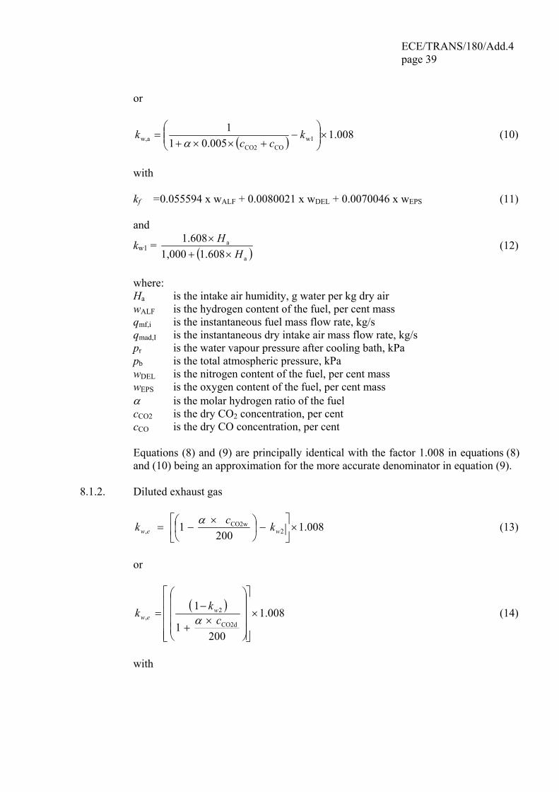
with kf = 0.055594 x wALF + 0.0080021 x wDEL + 0.0070046 x wEPS (11) and
kw1 = ( )a
a
1.6081,0001.608
HH
×+× (12)
where: Ha is the intake air humidity, g water per kg dry air wALF is the hydrogen content of the fuel, per cent mass qmf,i is the instantaneous fuel mass flow rate, kg/s qmad,I is the instantaneous dry intake air mass flow rate, kg/s pr is the water vapour pressure after cooling bath, kPa pb is the total atmospheric pressure, kPa wDEL is the nitrogen content of the fuel, per cent mass wEPS is the oxygen content of the fuel, per cent mass α is the molar hydrogen ratio of the fuel cCO2 is the dry CO2 concentration, per cent cCO is the dry CO concentration, per cent Equations (8) and (9) are principally identical with the factor 1.008 in equations (8)
and (10) being an approximation for the more accurate denominator in equation (9). 8.1.2. Diluted exhaust gas
1.008200
1 2CO2w
, ×⎥⎦
⎤⎢⎣
⎡−⎟
⎠⎞
⎜⎝⎛ ×
−= wew kck α (13)
or
( ) 1.008
2001
1CO2d
2, ×
⎥⎥⎥⎥
⎦
⎤
⎢⎢⎢⎢
⎣
⎡
⎟⎟⎟⎟
⎠
⎞
⎜⎜⎜⎜
⎝
⎛
×+
−= c
kk wew α (14)
with

ECE/TRANS/180/Add.4 page 40
⎭⎬⎫
⎩⎨⎧
⎥⎦
⎤⎢⎣
⎡⎟⎠⎞
⎜⎝⎛×+⎟
⎠⎞
⎜⎝⎛ −××+
⎥⎦
⎤⎢⎣
⎡⎟⎠⎞
⎜⎝⎛×+⎟
⎠⎞
⎜⎝⎛ −××
=
DH
DH
DH
DH
k
ad
ad
w 111608.1000,1
111608.1
2 (15)
where: α is themolar hydrogen ratio of the fuel cCO2w is the wet CO2 concentration, per cent cCO2d is the dry CO2 concentration, per cent Hd is the dilution air humidity, g water per kg dry air Ha is the intake air humidity, g water per kg dry air D is the dilution factor (see paragraph 8.4.2.4.2.) 8.1.3. Dilution air ( ) 1.0081 3, ×−= wdw kk (16) with
( )d
d3 608.1000,1
608.1H
Hkw ×+×
= (17)
where: Hdis the dilution air humidity, g water per kg dry air 8.2. NOx correction for humidity As the NOx emission depends on ambient air conditions, the NOx concentration shall
be corrected for humidity with the factors given in paragraph 8.2.1. or 8.2.2. The intake air humidity Ha may be derived from relative humidity measurement, dew point measurement, vapour pressure measurement or dry/wet bulb measurement using generally accepted equation.
8.2.1. Compression-ignition engines
832.0000,1
698.15Dh, +
×= aHk (18)
where: Ha is the intake air humidity, g water per kg dry air 8.2.2. Positive ignition engines kh.G = 0.6272 + 44.030 x 10⁻³ x Ha – 0.862 x 10⁻³ x Ha² (19)
ECE/TRANS/180/Add.4 page 41
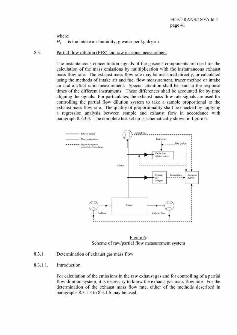
where: Ha is the intake air humidity, g water per kg dry air 8.3. Partial flow dilution (PFS) and raw gaseous measurement The instantaneous concentration signals of the gaseous components are used for the
calculation of the mass emissions by multiplication with the instantaneous exhaust mass flow rate. The exhaust mass flow rate may be measured directly, or calculated using the methods of intake air and fuel flow measurement, tracer method or intake air and air/fuel ratio measurement. Special attention shall be paid to the response times of the different instruments. These differences shall be accounted for by time aligning the signals. For particulates, the exhaust mass flow rate signals are used for controlling the partial flow dilution system to take a sample proportional to the exhaust mass flow rate. The quality of proportionality shall be checked by applying a regression analysis between sample and exhaust flow in accordance with paragraph 8.3.3.3. The complete test set up is schematically shown in figure 6.
Figure 6: Scheme of raw/partial flow measurement system
8.3.1. Determination of exhaust gas mass flow 8.3.1.1. Introduction For calculation of the emissions in the raw exhaust gas and for controlling of a partial
flow dilution system, it is necessary to know the exhaust gas mass flow rate. For the determination of the exhaust mass flow rate, either of the methods described in paragraphs 8.3.1.3 to 8.3.1.6 may be used.
ECE/TRANS/180/Add.4 page 42 8.3.1.2. Response time For the purpose of emissions calculation, the response time of either method
described in paragraphs 8.3.1.3 to 8.3.1.6 shall be equal to or less than the analyzer response time of ≤ 10 s, as required in paragraph 9.3.5.
For the purpose of controlling of a partial flow dilution system, a faster response is
required. For partial flow dilution systems with online control, the response time shall be ≤ 0.3 s. For partial flow dilution systems with look ahead control based on a pre-recorded test run, the response time of the exhaust flow measurement system shall be ≤ 5 s with a rise time of ≤ 1 s. The system response time shall be specified by the instrument manufacturer. The combined response time requirements for the exhaust gas flow and partial flow dilution system are indicated in paragraph 8.3.3.3.
8.3.1.3. Direct measurement method Direct measurement of the instantaneous exhaust flow shall be done by systems, such
as: (a) pressure differential devices, like flow nozzle, (details see ISO 5167) (b) ultrasonic flowmeter (c) vortex flowmeter Precautions shall be taken to avoid measurement errors which will impact emission
value errors. Such precautions include the careful installation of the device in the engine exhaust system according to the instrument manufacturers' recommendations and to good engineering practice. Especially, engine performance and emissions shall not be affected by the installation of the device.
The flowmeters shall meet the linearity requirements of paragraph 9.2. 8.3.1.4. Air and fuel measurement method This involves measurement of the airflow and the fuel flow with suitable flowmeters.
The calculation of the instantaneous exhaust gas flow shall be as follows: qmew,i = qmaw,i + qmf,i (20) where: qmew,i is the instantaneous exhaust mass flow rate, kg/s qmaw,i is the instantaneous intake air mass flow rate, kg/s qmf,i is the instantaneous fuel mass flow rate, kg/s The flowmeters shall meet the linearity requirements of paragraph 9.2., but shall be
accurate enough to also meet the linearity requirements for the exhaust gas flow.
ECE/TRANS/180/Add.4 page 43
8.3.1.5. Tracer measurement method This involves measurement of the concentration of a tracer gas in the exhaust. A known amount of an inert gas (e.g. pure helium) shall be injected into the exhaust
gas flow as a tracer. The gas is mixed and diluted by the exhaust gas, but shall not react in the exhaust pipe. The concentration of the gas shall then be measured in the exhaust gas sample.
In order to ensure complete mixing of the tracer gas, the exhaust gas sampling probe
shall be located at least 1 m or 30 times the diameter of the exhaust pipe, whichever is larger, downstream of the tracer gas injection point. The sampling probe may be located closer to the injection point if complete mixing is verified by comparing the tracer gas concentration with the reference concentration when the tracer gas is injected upstream of the engine.
The tracer gas flow rate shall be set so that the tracer gas concentration at engine idle
speed after mixing becomes lower than the full scale of the trace gas analyzer. The calculation of the exhaust gas flow shall be as follows:
( )bimix,
etiew, 60 cc
qq vm −×
×=
ρ (21)
where: qmew,i is the instantaneous exhaust mass flow rate, kg/s qvt is tracer gas flow rate, cm³/min cmix,i is the instantaneous concentration of the tracer gas after mixing, ppm ρe is the density of the exhaust gas, kg/m³ (cf. table 4) cb is the background concentration of the tracer gas in the intake air, ppm The background concentration of the tracer gas (cb) may be determined by averaging
the background concentration measured immediately before the test run and after the test run.
When the background concentration is less than 1 per cent of the concentration of the
tracer gas after mixing (cmix.i) at maximum exhaust flow, the background concentration may be neglected.
The total system shall meet the linearity requirements for the exhaust gas flow of
paragraph 9.2.
ECE/TRANS/180/Add.4 page 44 8.3.1.6. Airflow and air to fuel ratio measurement method This involves exhaust mass calculation from the airflow and the air to fuel ratio. The
calculation of the instantaneous exhaust gas mass flow is as follows:
⎟⎟⎠
⎞⎜⎜⎝
⎛×
+×=ist
iaw,iew,11
λA/Fqq mm (22)
with
γδεα
γεα
FA×+×+×+×+
⎟⎠⎞
⎜⎝⎛ +−+×
=32.06514.006715.99941.0079412.011
241138.0
/ st (23)
( )
( )4HCw
4COdCO2d
4COdCO2d
CO2d
4CO
CO2d
4COd
4HCw
4COd
i
101024
14.764
1022
3.510
1
3.5102
1
410
210
-100
−−
−−
−
−−
×+×+×⎟⎠⎞
⎜⎝⎛ +−+×
×+×
⎟⎟⎟⎟⎟
⎠
⎞
⎜⎜⎜⎜⎜
⎝
⎛
−−
××
+
×××
−×+⎟⎟
⎠
⎞⎜⎜⎝
⎛×−
×
=cccγεα
ccδε
cc
cc
αcc
λ (24)
where: qmew,i is the instantaneous exhaust mass flow rate, kg/s qmaw,i is the instantaneous intake air mass flow rate, kg/s A/Fst is the stoichiometric air to fuel ratio, kg/kg λi is the instantaneous excess air ratio cCO2d is the dry CO2 concentration, per cent cCOd is the dry CO concentration, ppm cHCw is the wet HC concentration, ppm Airflowmeter and analyzers shall meet the linearity requirements of paragraph 9.2.,
and the total system shall meet the linearity requirements for the exhaust gas flow of paragraph 9.2.
If an air to fuel ratio measurement equipment such as a zirconia type sensor is used
for the measurement of the excess air ratio, it shall meet the specifications of paragraph 9.3.2.7.
ECE/TRANS/180/Add.4 page 45
8.3.2. Determination of the gaseous components 8.3.2.1. Introduction The gaseous components in the raw exhaust gas emitted by the engine submitted for
testing shall be measured with the measurement and sampling systems described in paragraph 9.3. and Annex 3. The data evaluation is described in paragraph 8.3.2.3.
Two calculation procedures are described in paragraphs 8.3.2.4. and 8.3.2.5., which
are equivalent for the reference fuels of Annex 2. The procedure in paragraph 8.3.2.4. is more straightforward, since it uses tabulated u values for the ratio between component and exhaust gas density. The procedure in paragraph 8.3.2.5. is more accurate for fuel qualities that deviate from the specifications in Annex 2, but requires elementary analysis of the fuel composition.
8.3.2.2. Sampling for gaseous emissions The gaseous emissions sampling probes shall be fitted at least 0.5 m or 3 times the
diameter of the exhaust pipe - whichever is the larger - upstream of the exit of the exhaust gas system but sufficiently close to the engine as to ensure an exhaust gas temperature of at least 343 K (70 °C) at the probe.
In the case of a multi-cylinder engine with a branched exhaust manifold, the inlet of
the probe shall be located sufficiently far downstream so as to ensure that the sample is representative of the average exhaust emissions from all cylinders. In multi-cylinder engines having distinct groups of manifolds, such as in a "Vee" engine configuration, it is recommended to combine the manifolds upstream of the sampling probe. If this is not practical, it is permissible to acquire a sample from the group with the highest CO2 emission. For exhaust emission calculation the total exhaust mass flow shall be used.
If the engine is equipped with an exhaust after-treatment system, the exhaust sample
shall be taken downstream of the exhaust after-treatment system. 8.3.2.3. Data evaluation For the evaluation of the gaseous emissions, the raw emission concentrations (HC,
CO and NOx) and the exhaust gas mass flow rate shall be recorded and stored with at least 2 Hz on a computer system. All other data shall be recorded with a sample rate of at least 1 Hz. For analogue analyzers, the response shall be recorded, and the calibration data may be applied online or offline during the data evaluation.
For calculation of the mass emission of the gaseous components, the traces of the
recorded concentrations and the trace of the exhaust gas mass flow rate shall be time aligned by the transformation time as defined in paragraph 3.1.28. Therefore, the response time of each gaseous emissions analyzer and of the exhaust gas mass flow
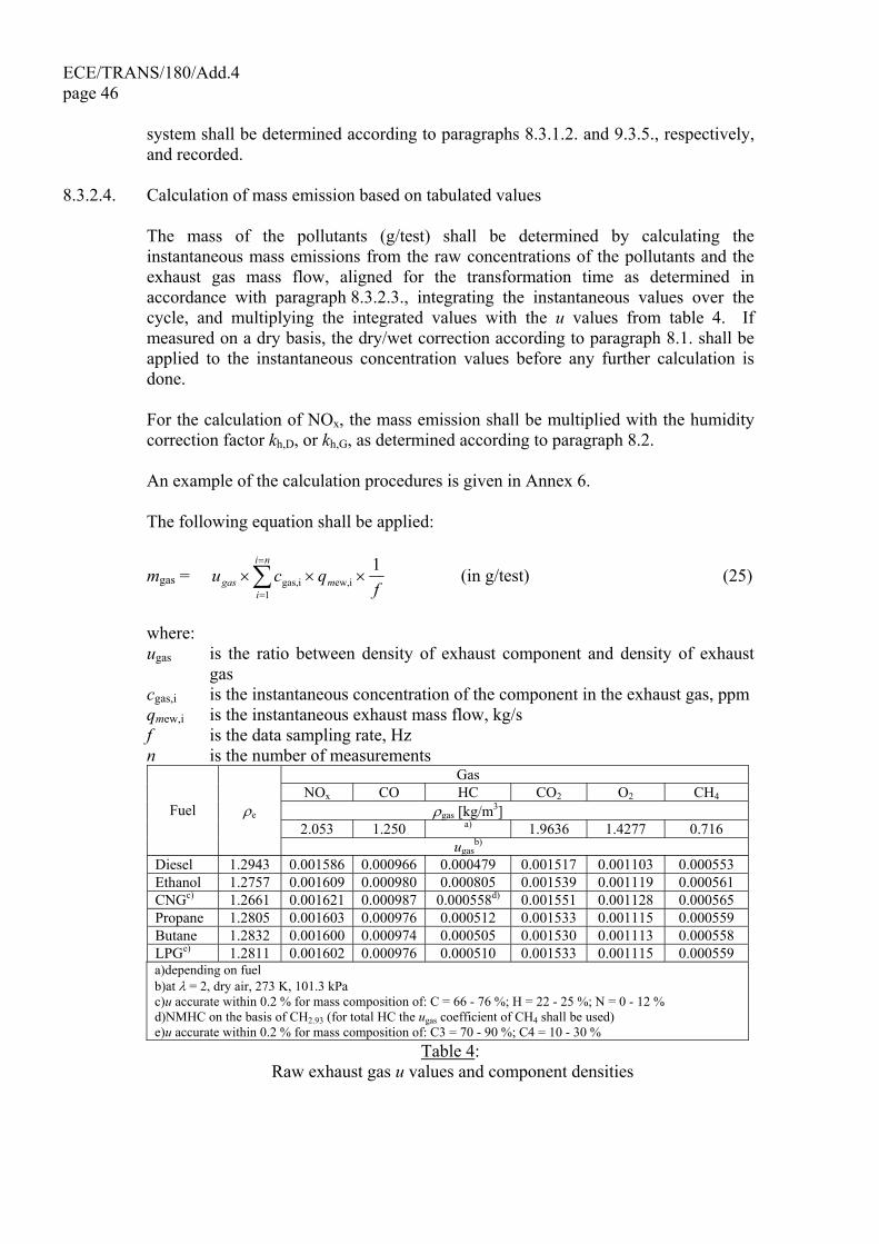
ECE/TRANS/180/Add.4 page 46
system shall be determined according to paragraphs 8.3.1.2. and 9.3.5., respectively, and recorded.
8.3.2.4. Calculation of mass emission based on tabulated values The mass of the pollutants (g/test) shall be determined by calculating the
instantaneous mass emissions from the raw concentrations of the pollutants and the exhaust gas mass flow, aligned for the transformation time as determined in accordance with paragraph 8.3.2.3., integrating the instantaneous values over the cycle, and multiplying the integrated values with the u values from table 4. If measured on a dry basis, the dry/wet correction according to paragraph 8.1. shall be applied to the instantaneous concentration values before any further calculation is done.
For the calculation of NOx, the mass emission shall be multiplied with the humidity
correction factor kh,D, or kh,G, as determined according to paragraph 8.2. An example of the calculation procedures is given in Annex 6. The following equation shall be applied:
mgas = ∑=
=
×××ni
imgas f
qcu1
iew,igas,1 (in g/test) (25)
where: ugas is the ratio between density of exhaust component and density of exhaust
gas cgas,i is the instantaneous concentration of the component in the exhaust gas, ppm qmew,i is the instantaneous exhaust mass flow, kg/s f is the data sampling rate, Hz n is the number of measurements
Gas NOx CO HC CO2 O2 CH4
ρgas [kg/m3] 2.053 1.250 a) 1.9636 1.4277 0.716
Fuel ρe
ugasb)
Diesel 1.2943 0.001586 0.000966 0.000479 0.001517 0.001103 0.000553 Ethanol 1.2757 0.001609 0.000980 0.000805 0.001539 0.001119 0.000561 CNGc) 1.2661 0.001621 0.000987 0.000558d) 0.001551 0.001128 0.000565 Propane 1.2805 0.001603 0.000976 0.000512 0.001533 0.001115 0.000559 Butane 1.2832 0.001600 0.000974 0.000505 0.001530 0.001113 0.000558 LPGe) 1.2811 0.001602 0.000976 0.000510 0.001533 0.001115 0.000559 a)depending on fuel b)at λ = 2, dry air, 273 K, 101.3 kPa c)u accurate within 0.2 % for mass composition of: C = 66 - 76 %; H = 22 - 25 %; N = 0 - 12 % d)NMHC on the basis of CH2.93 (for total HC the ugas coefficient of CH4 shall be used) e)u accurate within 0.2 % for mass composition of: C3 = 70 - 90 %; C4 = 10 - 30 %
Table 4: Raw exhaust gas u values and component densities
ECE/TRANS/180/Add.4 page 47
8.3.2.5. Calculation of mass emission based on exact equations The mass of the pollutants (g/test) shall be determined by calculating the
instantaneous mass emissions from the raw concentrations of the pollutants, the u values and the exhaust gas mass flow, aligned for the transformation time as determined in accordance with paragraph 8.3.2.3. and integrating the instantaneous values over the cycle. If measured on a dry basis, the dry/wet correction according to paragraph 8.1. shall be applied to the instantaneous concentration values before any further calculation is done.
For the calculation of NOx, the mass emission shall be multiplied with the humidity
correction factor kh,D, or kh,G, as determined according to paragraph 8.2. The following equation shall be applied:
mgas = ∑=
=
×××ni
im f
qcu1
ew,igas,igas,i1 (in g/test) (26)
where: ugas,i is the instantaneous density ratio of exhaust component and exhaust gas cgas,i is the instantaneous concentration of the component in the exhaust gas, ppm qmew,i is the instantaneous exhaust mass flow, kg/s f is the data sampling rate, Hz n is the number of measurements The instantaneous u values shall be calculated as follows: ugas,i = Mgas / (Me,i x 1,000) (27) or ugas,i =ρgas / (ρe,i x 1,000) (28) with ρgas = Mgas / 22.414 (29) where: Mgas is the molar mass of the gas component, g/mol (cf. Annex 6) Me,i is the instantaneous molar mass of the exhaust gas, g/mol ρgas is the density of the gas component, kg/m3 ρe,i is the instantaneous density of the exhaust gas, kg/m3 The molar mass of the exhaust, Me, shall be derived for a general fuel composition
CHαOεNδSγ under the assumption of complete combustion, as follows:

ECE/TRANS/180/Add.4 page 48
3a
a
3a
iaw,
if,
iaw,
if,
ie,
101
19994.1500794.12
10
065.320067.149994.1500794.1011.12224
1
−
−
×+
++×
×
+×+×+×+×+
++×
+
=
HM
H
M
m
m
m
m
γδεα
δεα
(30)
where: qmaw,i is the instantaneous intake air mass flow rate on wet basis, kg/s qmf,i is the instantaneous fuel mass flow rate, kg/s Ha is the intake air humidity, g water per kg dry air Ma is the molar mass of the dry intake air = 28.965 g/mol The exhaust density ρe shall be derived, as follows:
)/( 1,000 + 1.2434 + 773.4
)/( 1,000 + 1,000 =
iad,if,fa
iad,if,aie,
mm
mm
qqkHqqH
ρ×××
×+ (31)
where: qmad,i is the instantaneous intake air mass flow rate on dry basis, kg/s qmf,i is the instantaneous fuel mass flow rate, kg/s Ha is the intake air humidity, g water per kg dry air kf is the fuel specific factor according to equation 11 in paragraph 8.1.1. 8.3.3. Particulate determination 8.3.3.1. Introduction The determination of the particulates requires dilution of the sample with filtered
ambient air, synthetic air or nitrogen. The partial flow dilution system shall be set to completely eliminate water condensation in the dilution and sampling systems, and maintain the temperature of the diluted exhaust gas between 315 K (42 °C) and 325 K (52 °C) immediately upstream of the filter holders. Dehumidifying the dilution air before entering the dilution system is permitted, and especially useful if dilution air humidity is high. The temperature of the dilution air shall be ≥ 288 K (15 °C) in close proximity to the entrance into the dilution tunnel.
The partial flow dilution system has to be designed to extract a proportional raw
exhaust sample from the engine exhaust stream, thus responding to excursions in the exhaust stream flow rate, and introduce dilution air to this sample to achieve a temperature between 315 K (42 °C) and 325 K (52 °C) at the test filter. For this it is essential that the dilution ratio or the sampling ratio rd or rs be determined such that the accuracy requirements of paragraph 9.4.4. are fulfilled.
To determine the mass of the particulates, a particulate sampling system, a
particulate sampling filter, a microgram balance, and a temperature and humidity

ECE/TRANS/180/Add.4 page 49
controlled weighing chamber, are required. The details of the system are described in paragraph 9.4.
8.3.3.2. Particulate sampling In general, the particulate sampling probe shall be installed in close proximity to the
gaseous emissions sampling probe, but sufficiently distant as to not cause interference. Therefore, the installation provisions of paragraph 8.3.2.2. also apply to particulate sampling. The sampling line shall conform to the requirements laid down in Annex 3.
In the case of a multi-cylinder engine with a branched exhaust manifold, the inlet of
the probe shall be located sufficiently far downstream so as to ensure that the sample is representative of the average exhaust emissions from all cylinders. In multi-cylinder engines having distinct groups of manifolds, such as in a "Vee" engine configuration, it is recommended to combine the manifolds upstream of the sampling probe. If this is not practical, it is permissible to acquire a sample from the group with the highest particulate emission. For exhaust emission calculation the total exhaust mass flow of the manifold shall be used.
8.3.3.3. System response time For the control of a partial flow dilution system, a fast system response is required.
The transformation time for the system shall be determined by the procedure in paragraph 9.4.7.3. If the combined transformation time of the exhaust flow measurement (see paragraph 8.3.1.2.) and the partial flow system is ≤ 0.3 s, online control shall be used. If the transformation time exceeds 0.3 s, look ahead control based on a pre-recorded test run shall be used. In this case, the combined rise time shall be ≤ 1 s and the combined delay time ≤ 10 s.
The total system response shall be designed as to ensure a representative sample of
the particulates, qmp,i, proportional to the exhaust mass flow. To determine the proportionality, a regression analysis of qmp,i versus qmew,i shall be conducted on a minimum 5 Hz data acquisition rate, and the following criteria shall be met:
(a) The coefficient of determination r2 of the linear regression between qmp,i and qmew,i shall not be less than 0.95.
(b) The standard error of estimate of qmp,i on qmew,i shall not exceed 5 per cent of qmp maximum.
(c) qmp intercept of the regression line shall not exceed ± 2 per cent of qmp maximum.
Look-ahead control is required if the combined transformation times of the
particulate system, t50,P and of the exhaust mass flow signal, t50,F are > 0.3 s. In this case, a pre-test shall be run, and the exhaust mass flow signal of the pre-test be used for controlling the sample flow into the particulate system. A correct control of the partial dilution system is obtained, if the time trace of qmew,pre of the pre-test, which controls qmp, is shifted by a "look-ahead" time of t50,P + t50,F.
ECE/TRANS/180/Add.4 page 50 For establishing the correlation between qmp,i and qmew,i the data taken during the
actual test shall be used, with qmew,i time aligned by t50,F relative to qmp,i (no contribution from t50,P to the time alignment). That is, the time shift between qmew and qmp is the difference in their transformation times that were determined in paragraph 9.4.7.3.
8.3.3.4. Data evaluation The tare weight of the filter, as determined according to paragraph 7.8.2.2., shall be
subtracted from the gross weight of the filter, as determined according to paragraph 7.8.4.5., which results in the particulate sample mass mf. For the evaluation of the particulate concentration, the total sample mass (msep) through the filter over the test cycle shall be recorded.
With the prior approval of the type approval or certification authority, the particulate
mass may be corrected for the particulate level of the dilution air, as determined in paragraph 7.8.2.5., in line with good engineering practice and the specific design features of the particulate measurement system used.
8.3.3.5. Calculation of mass emission Depending on system design, the mass of particulates (g/test) shall be calculated by
either of the methods in paragraphs 8.3.3.5.1. or 8.3.3.5.2 after buoyancy correction of the particulate sample mass according to paragraph 9.4.3.5. An example of the calculation procedures is given in Annex 6.
8.3.3.5.1. Calculation based on sample ratio mPM = mf / (rs x 1,000) (32) where: mfis the particulate mass sampled over the cycle, mg rsis the average sample ratio over the test cycle with
rs = sed
sep
ew
se
mm
mm
× (33)
where: mse is the sample mass over the cycle, kg mewis the total exhaust mass flow over the cycle, kg msepis the mass of diluted exhaust gas passing the particulate collection filters, kg msedis the mass of diluted exhaust gas passing the dilution tunnel, kg In case of the total sampling type system, msep and msed are identical.
ECE/TRANS/180/Add.4 page 51
8.3.3.5.2.Calculation based on dilution ratio
mPM = 1,000
edf
sep
f mmm
× (34)
where: mf is the particulate mass sampled over the cycle, mg msep is the mass of diluted exhaust gas passing the particulate collection filters, kg medf is the mass of equivalent diluted exhaust gas over the cycle, kg The total mass of equivalent diluted exhaust gas mass over the cycle shall be
determined as follows:
medf = f
qni
im
11
iedf, ×∑=
=
(35)
qmedf,I = qmew,i x rd,i (36)
rd,i = ⎟⎠⎞
⎜⎝⎛ − i,dwi,dew
i,dew
,m,m
,m
qqq
(37)
where: qmedf,i is the instantaneous equivalent diluted exhaust mass flow rate, kg/s qmew,i is the instantaneous exhaust mass flow rate, kg/s rd,i is the instantaneous dilution ratio qmdew,i is the instantaneous diluted exhaust mass flow rate, kg/s qmdw,i is the instantaneous dilution air mass flow rate, kg/s f is the data sampling rate, Hz n is the number of measurements 8.4. Full flow dilution measurement (CVS) The concentration signals, either by integration over the cycle or by bag sampling, of
the gaseous components shall be used for the calculation of the mass emissions by multiplication with the diluted exhaust mass flow rate. The exhaust mass flow rate shall be measured with a constant volume sampling (CVS) system, which may use a positive displacement pump (PDP), a critical flow venturi (CFV) or a subsonic venturi (SSV) with or without flow compensation.
For bag sampling and particulate sampling, a proportional sample shall be taken from
the diluted exhaust gas of the CVS system. For a system without flow compensation, the ratio of sample flow to CVS flow must not vary by more than ± 2.5 per cent from the set point of the test. For a system with flow compensation, each individual flow rate shall be constant within ± 2.5 per cent of its respective target flow rate.
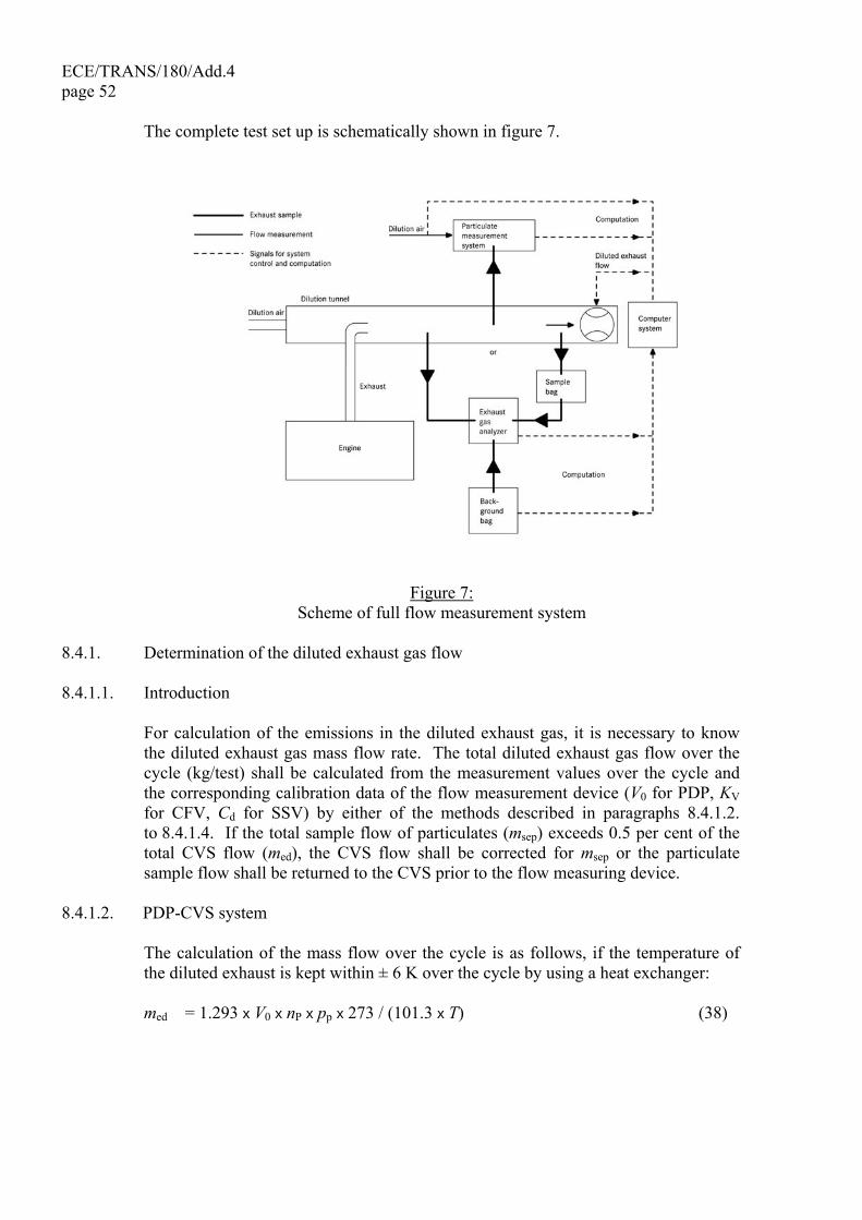
ECE/TRANS/180/Add.4 page 52 The complete test set up is schematically shown in figure 7.
Figure 7: Scheme of full flow measurement system
8.4.1. Determination of the diluted exhaust gas flow 8.4.1.1. Introduction For calculation of the emissions in the diluted exhaust gas, it is necessary to know
the diluted exhaust gas mass flow rate. The total diluted exhaust gas flow over the cycle (kg/test) shall be calculated from the measurement values over the cycle and the corresponding calibration data of the flow measurement device (V0 for PDP, KV for CFV, Cd for SSV) by either of the methods described in paragraphs 8.4.1.2. to 8.4.1.4. If the total sample flow of particulates (msep) exceeds 0.5 per cent of the total CVS flow (med), the CVS flow shall be corrected for msep or the particulate sample flow shall be returned to the CVS prior to the flow measuring device.
8.4.1.2. PDP-CVS system The calculation of the mass flow over the cycle is as follows, if the temperature of
the diluted exhaust is kept within ± 6 K over the cycle by using a heat exchanger: med = 1.293 x V0 x nP x pp x 273 / (101.3 x T) (38)
ECE/TRANS/180/Add.4 page 53
where: V0 is the volume of gas pumped per revolution under test conditions, m³/rev nP is the total revolutions of pump per test pp is the absolute pressure at pump inlet, kPa T is the average temperature of the diluted exhaust gas at pump inlet, K If a system with flow compensation is used (i.e. without heat exchanger), the
instantaneous mass emissions shall be calculated and integrated over the cycle. In this case, the instantaneous mass of the diluted exhaust gas shall be calculated as follows:
med,i = 1.293 x V0 x nP,i x pp x 273 / (101.3 x T) (39) where: nP,i is the total revolutions of pump per time interval 8.4.1.3. CFV-CVS system The calculation of the mass flow over the cycle is as follows, if the temperature of
the diluted exhaust is kept within ± 11 K over the cycle by using a heat exchanger: med = 1.293 x t x Kv x pp / T 0.5 (40) where: t is the cycle time, s KV is the calibration coefficient of the critical flow venturi for standard conditions, pp is the absolute pressure at venturi inlet, kPa T is the absolute temperature at venturi inlet, K If a system with flow compensation is used (i.e. without heat exchanger), the
instantaneous mass emissions shall be calculated and integrated over the cycle. In this case, the instantaneous mass of the diluted exhaust gas shall be calculated as follows:
med,i = 1.293 x Δti x KV x pp / T 0.5 (41) where: Δti is the time interval, s 8.4.1.4. SSV-CVS system The calculation of the mass flow over the cycle shall be as follows, if the temperature
of the diluted exhaust is kept within ± 11 K over the cycle by using a heat exchanger: med = 1.293 x QSSV (42) with

ECE/TRANS/180/Add.4 page 54
( )⎥⎥⎦
⎤
⎢⎢⎣
⎡
⎟⎟⎠
⎞⎜⎜⎝
⎛
−⋅−= 4286.1
p4
D
7143.1p
4286.1pd
2V0SSV 1
11rr
rrT
pCdAQ p (43)
where:
A0 is 0.006111 in SI units of ⎟⎠⎞
⎜⎝⎛
⎟⎟⎟
⎠
⎞
⎜⎜⎜
⎝
⎛
⎟⎟⎠
⎞⎜⎜⎝
⎛2
21
3 1min mmkPa
Km
dV is the diameter of the SSV throat, m Cd is the discharge coefficient of the SSV pp is the absolute pressure at venturi inlet, kPa T is the temperature at the venturi inlet, K
rp is the ratio of the SSV throat to inlet absolute static pressure, appΔ
−1
rD is the ratio of the SSV throat diameter, d, to the inlet pipe inner diameter D If a system with flow compensation is used (i.e. without heat exchanger), the
instantaneous mass emissions shall be calculated and integrated over the cycle. In this case, the instantaneous mass of the diluted exhaust gas shall be calculated as follows:
med = 1.293 x QSSV x Δti (44) where: Δti is the time interval, s The real time calculation shall be initialized with either a reasonable value for Cd,
such as 0.98, or a reasonable value of Qssv. If the calculation is initialized with Qssv, the initial value of Qssv shall be used to evaluate the Reynolds number.
During all emissions tests, the Reynolds number at the SSV throat shall be in the
range of Reynolds numbers used to derive the calibration curve developed in paragraph 9.5.4.
8.4.2. Determination of the gaseous components 8.4.2.1. Introduction The gaseous components in the diluted exhaust gas emitted by the engine submitted
for testing shall be measured by the methods described in Annex 3. Dilution of the exhaust shall be done with filtered ambient air, synthetic air or nitrogen. The flow capacity of the full flow system shall be large enough to completely eliminate water condensation in the dilution and sampling systems. Data evaluation and calculation procedures are described in paragraphs 8.4.2.3. and 8.4.2.4.
ECE/TRANS/180/Add.4 page 55
8.4.2.2. Sampling for gaseous emissions The exhaust pipe between the engine and the full flow dilution system shall conform
to the requirements laid down in Annex 3. The gaseous emissions sample probe(s) shall be installed in the dilution tunnel at a point where the dilution air and exhaust gas are well mixed, and in close proximity to the particulates sampling probe.
Sampling can generally be done in two ways: (a) the emissions are sampled into a sampling bag over the cycle and measured
after completion of the test; for HC, the sample bag shall be heated to 464 ± 11 K (191 ± 11°C), for NOx, the sample bag temperature shall be above the dew point temperature;
(b) the emissions are sampled continuously and integrated over the cycle. The background concentrations shall be sampled upstream of the dilution tunnel into
a sampling bag, and shall be subtracted from the emissions concentration according to paragraph 8.4.2.4.2.
8.4.2.3. Data evaluation For continuous sampling, the emission concentrations (HC, CO and NOx) shall be
recorded and stored with at least 1 Hz on a computer system, for bag sampling one mean value per test is required. The diluted exhaust gas mass flow rate and all other data shall be recorded with a sample rate of at least 1 Hz. For analogue analyzers the response will be recorded, and the calibration data may be applied online or offline during the data evaluation.
8.4.2.4. Calculation of mass emission 8.4.2.4.1. Systems with constant mass flow For systems with heat exchanger, the mass of the pollutants shall be determined from
the following equation: mgas = ugas x cgas x med (in g/test) (45) where: ugas is the ratio between density of exhaust component and density of air cgas is the average background corrected concentration of the component, ppm med is the total diluted exhaust mass over the cycle, kg If measured on a dry basis, the dry/wet correction according to paragraph 8.1. shall
be applied. For the calculation of NOx, the mass emission shall be multiplied with the humidity
correction factor kh,D, or kh,G, as determined according to paragraph 8.2.
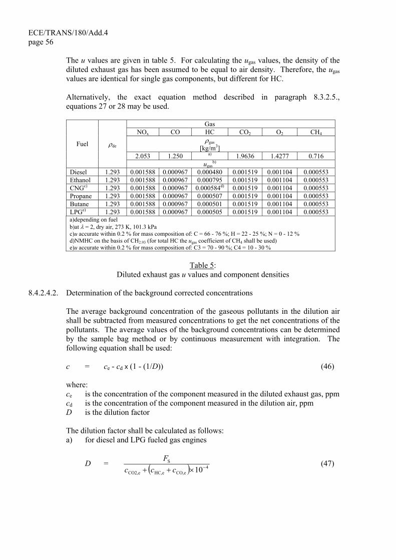
ECE/TRANS/180/Add.4 page 56 The u values are given in table 5. For calculating the ugas values, the density of the
diluted exhaust gas has been assumed to be equal to air density. Therefore, the ugas values are identical for single gas components, but different for HC.
Alternatively, the exact equation method described in paragraph 8.3.2.5.,
equations 27 or 28 may be used.
Gas NOx CO HC CO2 O2 CH4
ρgas [kg/m3]
2.053 1.250 a) 1.9636 1.4277 0.716
Fuel ρde
ugasb)
Diesel 1.293 0.001588 0.000967 0.000480 0.001519 0.001104 0.000553 Ethanol 1.293 0.001588 0.000967 0.000795 0.001519 0.001104 0.000553 CNGc) 1.293 0.001588 0.000967 0.000584d) 0.001519 0.001104 0.000553 Propane 1.293 0.001588 0.000967 0.000507 0.001519 0.001104 0.000553 Butane 1.293 0.001588 0.000967 0.000501 0.001519 0.001104 0.000553 LPGe) 1.293 0.001588 0.000967 0.000505 0.001519 0.001104 0.000553 a)depending on fuel b)at λ = 2, dry air, 273 K, 101.3 kPa c)u accurate within 0.2 % for mass composition of: C = 66 - 76 %; H = 22 - 25 %; N = 0 - 12 % d)NMHC on the basis of CH2.93 (for total HC the ugas coefficient of CH4 shall be used) e)u accurate within 0.2 % for mass composition of: C3 = 70 - 90 %; C4 = 10 - 30 %
Table 5:
Diluted exhaust gas u values and component densities 8.4.2.4.2. Determination of the background corrected concentrations The average background concentration of the gaseous pollutants in the dilution air
shall be subtracted from measured concentrations to get the net concentrations of the pollutants. The average values of the background concentrations can be determined by the sample bag method or by continuous measurement with integration. The following equation shall be used:
c = ce - cd x (1 - (1/D)) (46) where: ce is the concentration of the component measured in the diluted exhaust gas, ppm cd is the concentration of the component measured in the dilution air, ppm D is the dilution factor The dilution factor shall be calculated as follows: a) for diesel and LPG fueled gas engines
D = ( ) 4eCO,eHC,eCO2,
S
10−×++ cccF (47)
ECE/TRANS/180/Add.4 page 57
b) for NG fueled gas engines
D = ( ) 4eCO,eNMHC,eCO2,
S
10−×++ cccF (48)
where: cCO2,e is the wet concentration of CO2 in the diluted exhaust gas, per cent vol cHC,e is the wet concentration of HC in the diluted exhaust gas, ppm C1 cNMHC,e is the wet concentration of NMHC in the diluted exhaust gas, ppm C1 cCO,e is the wet concentration of CO in the diluted exhaust gas, ppm FS is the stoichiometric factor The stoichiometric factor shall be calculated as follows:
FS = ⎟⎠⎞
⎜⎝⎛ +×+
×
4176.3
2+1
1100αα
(49)
where: α is the molar hydrogen ratio of the fuel (H/C) Alternatively, if the fuel composition is not known, the following stoichiometric
factors may be used: FS (diesel) = 13.4 FS (LPG) = 11.6 FS (NG) = 9.5 8.4.2.4.3 Systems with flow compensation For systems without heat exchanger, the mass of the pollutants (g/test) shall be
determined by calculating the instantaneous mass emissions and integrating the instantaneous values over the cycle. Also, the background correction shall be applied directly to the instantaneous concentration value. The following equation shall be applied:
mgas = ( )[ ] ( )( )[ ]∑=
×−××−××n
1i/ gasdedgaseied, 11 uDcmucm (50)
where: ce is the concentration of the component measured in the diluted exhaust gas, ppm cd is the concentration of the component measured in the dilution air, ppm med,i is the instantaneous mass of the diluted exhaust gas, kg med is the total mass of diluted exhaust gas over the cycle, kg ugas is the tabulated value from table 5 D is the dilution factor

ECE/TRANS/180/Add.4 page 58 8.4.3. Particulate determination 8.4.3.1. Introduction The determination of the particulates requires double dilution of the sample with
filtered ambient air, synthetic air or nitrogen. The flow capacity of the full flow double dilution system shall be large enough to completely eliminate water condensation in the dilution and sampling systems, and maintain the temperature of the diluted exhaust gas between 315 K (42 °C) and 325 K (52 °C) immediately upstream of the filter holders. Dehumidifying the dilution air before entering the dilution system is permitted, and especially useful if dilution air humidity is high. The temperature of the dilution air shall be ≥ 288 K (15 °C) in close proximity to the entrance into the dilution tunnel.
To determine the mass of the particulates, a particulate sampling system, a
particulate sampling filter, a microgram balance, and a temperature and humidity controlled weighing chamber, are required. The details of the system are described in paragraph 9.4.
8.4.3.2. Particulate sampling The particulate sampling probe shall be installed in close proximity to the gaseous
emissions sampling probe, but sufficiently distant as to not cause interference, in the dilution tunnel. Therefore, the installation provisions of paragraph 8.3.2.2. also apply to particulate sampling. The sampling line shall conform to the requirements laid down in Annex 3.
8.4.3.3. Calculation of mass emission The particulate mass (g/test) shall be calculated after buoyancy correction of the
particulate sample mass according to paragraph 9.4.3.5. as follows:
mPM = 1,000
ed
sep
f mmm
× (51)
where: mf is the particulate mass sampled over the cycle, mg msep is the mass of diluted exhaust gas passing the particulate collection filters, kg med is the mass of diluted exhaust gas over the cycle, kg with msep = mset - mssd (52) where: mset is the mass of double diluted exhaust gas through particulate filter, kg mssd is the mass of secondary dilution air, kg
ECE/TRANS/180/Add.4 page 59
If the particulate background level of the dilution air is determined in accordance with paragraph 7.8.2.5, the particulate mass may be background corrected. In this case, the particulate mass (g/test) shall be calculated as follows:
mPM = 1,000
1-1 ed
sd
b
sep
f mDm
mmm
××− ⎥⎦
⎤⎢⎣
⎡⎟⎠
⎞⎜⎝
⎛⎟⎠⎞
⎜⎝⎛ (53)
where: msep is the mass of diluted exhaust gas passing the particulate collection filters, kg med is the mass of diluted exhaust gas over the cycle, kg msd is the mass of dilution air sampled by background particulate sampler, kg mb is the mass of the collected background particulates of the dilution air, mg D is the dilution factor as determined in paragraph 8.4.2.4.2. 8.5. General calculations 8.5.1. Calculation of NMHC and CH4 with the non-methane cutter The concentration of NMHC and CH4 shall be calculated as follows:
( )EE
cEcc
ME
r)HC(w/CutteMer)HC(w/oCuttNMHC
1−
−−×= (54)
( )EE
c Ecc
ME
Eer)HC(w/oCuttr)HC(w/CutteCH4
1−
−×−= (55)
where: cHC(w/Cutter) is the HC concentration with sample gas flowing through the NMC, ppm cHC(w/oCutter) is the HC concentration with sample gas bypassing the NMC, ppm EM is the methane efficiency as determined per paragraph 9.3.8.1. EE is the ethane efficiency as determined per paragraph 9.3.8.2. 8.5.2. Calculation of the specific emissions The specific emissions egas or ePM (g/kWh) shall be calculated for each individual
component in the following ways depending on the type of test cycle. 8.5.2.1. Test result For the WHSC, hot WHTC, or cold WHTC, the following formula shall be applied:
actW
me = (56)
where: m is the mass emission of the component, g/test Wact is the actual cycle work as determined according to paragraph 7.7.1., kWh
ECE/TRANS/180/Add.4 page 60 For the WHTC, the final test result shall be a weighted average from cold start test
and hot start test by using either of the following options:
( ) ( )
( ) ( )tWWmme
hoact,coldact,
hotcold
86.014.086.014.0
×+××+×
= (57a)
( ) ( )
( ) ( )tWWmme
hoact,coldact,
hotcold
9.01.09.01.0
×+××+×
= (57b)
The option shall be selected by the Contracting Parties.
8.5.2.2. Exhaust after-treatment systems with periodic regeneration The hot start emissions shall be weighted as follows:
r
rrw nn
nn+
×+×=
eee (58)
where: n is the number of WHTC hot start tests outside regenerations nr is the number of WHTC hot start tests during regeneration (minimum one test) e is the average specific emission outside regeneration, g/kWh er is the average specific emission during regeneration, g/kWh The regeneration factor kr shall be determined as follows:
e
ek wr = (59)

ECE/TRANS/180/Add.4 page 61
The regeneration factor kr : (a) shall be applied to the weighted WHTC test result of paragraph 8.5.2.2., (b) may be applied to the WHSC and cold WHTC, if a regeneration occurs during
the cycle, (c) may be extended to other members of the same engine family, (d) may be extended to other engine families using the same aftertreatment system
with the prior approval of the type approval or certification authority based on technical evidence to be supplied by the manufacturer that the emissions are similar.
9. MEASUREMENT EQUIPMENT This gtr does not contain details of flow, pressure, and temperature measuring
equipment or systems. Instead, only the linearity requirements of such equipment or systems necessary for conducting an emissions test are given in paragraph 9.2.
9.1. Dynamometer specification An engine dynamometer with adequate characteristics to perform the appropriate test
cycle described in paragraphs 7.2. and 7.3. shall be used. The instrumentation for torque and speed measurement shall allow the measurement
accuracy of the shaft power as needed to comply with the cycle validation criteria. Additional calculations may be necessary. The accuracy of the measuring equipment shall be such that the linearity requirements given in paragraph 9.2., table 6 are not exceeded.
9.2. Linearity requirements The calibration of all measuring instruments and systems shall be traceable to
national (international) standards. The measuring instruments and systems shall comply with the linearity requirements given in table 6. The linearity verification according to paragraph 9.2.1. shall be performed for the gas analyzers at least every 3 months or whenever a system repair or change is made that could influence calibration. For the other instruments and systems, the linearity verification shall be done as required by internal audit procedures, by the instrument manufacturer or in accordance with ISO 9000 requirements.
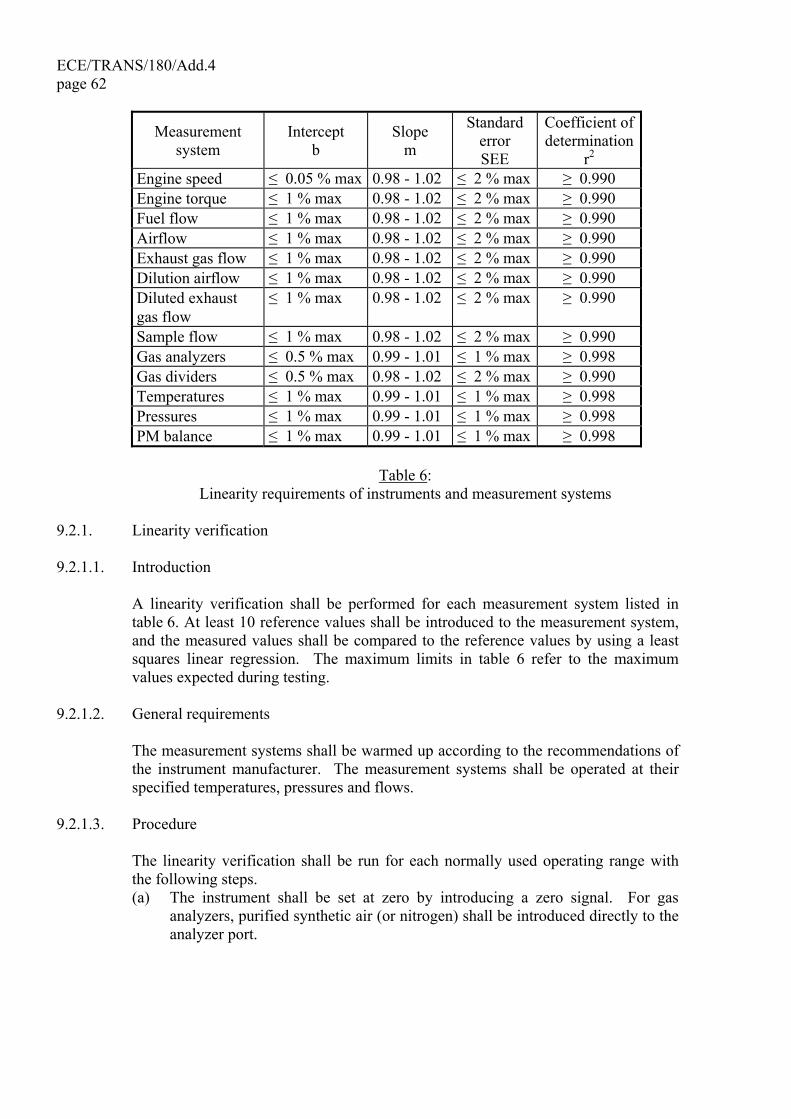
ECE/TRANS/180/Add.4 page 62
Measurement system
Intercept b
Slope m
Standard error SEE
Coefficient of determination
r2 Engine speed ≤ 0.05 % max 0.98 - 1.02 ≤ 2 % max ≥ 0.990 Engine torque ≤ 1 % max 0.98 - 1.02 ≤ 2 % max ≥ 0.990 Fuel flow ≤ 1 % max 0.98 - 1.02 ≤ 2 % max ≥ 0.990 Airflow ≤ 1 % max 0.98 - 1.02 ≤ 2 % max ≥ 0.990 Exhaust gas flow ≤ 1 % max 0.98 - 1.02 ≤ 2 % max ≥ 0.990 Dilution airflow ≤ 1 % max 0.98 - 1.02 ≤ 2 % max ≥ 0.990 Diluted exhaust gas flow
≤ 1 % max 0.98 - 1.02 ≤ 2 % max ≥ 0.990
Sample flow ≤ 1 % max 0.98 - 1.02 ≤ 2 % max ≥ 0.990 Gas analyzers ≤ 0.5 % max 0.99 - 1.01 ≤ 1 % max ≥ 0.998 Gas dividers ≤ 0.5 % max 0.98 - 1.02 ≤ 2 % max ≥ 0.990 Temperatures ≤ 1 % max 0.99 - 1.01 ≤ 1 % max ≥ 0.998 Pressures ≤ 1 % max 0.99 - 1.01 ≤ 1 % max ≥ 0.998 PM balance ≤ 1 % max 0.99 - 1.01 ≤ 1 % max ≥ 0.998
Table 6:
Linearity requirements of instruments and measurement systems 9.2.1. Linearity verification 9.2.1.1. Introduction A linearity verification shall be performed for each measurement system listed in
table 6. At least 10 reference values shall be introduced to the measurement system, and the measured values shall be compared to the reference values by using a least squares linear regression. The maximum limits in table 6 refer to the maximum values expected during testing.
9.2.1.2. General requirements The measurement systems shall be warmed up according to the recommendations of
the instrument manufacturer. The measurement systems shall be operated at their specified temperatures, pressures and flows.
9.2.1.3. Procedure The linearity verification shall be run for each normally used operating range with
the following steps. (a) The instrument shall be set at zero by introducing a zero signal. For gas
analyzers, purified synthetic air (or nitrogen) shall be introduced directly to the analyzer port.

ECE/TRANS/180/Add.4 page 63
(b) The instrument shall be spanned by introducing a span signal. For gas analyzers, an appropriate span gas shall be introduced directly to the analyzer port.
(c) The zero procedure of (a) shall be repeated. (d) The verification shall be established by introducing at least 10 reference values
(including zero) that are within the range from zero to the highest values expected during emission testing. For gas analyzers, known gas concentrations shall be introduced directly to the analyzer port.
(e) At a recording frequency of at least 1 Hz, the reference values shall be measured and the measured values recorded for 30 s.
(f) The arithmetic mean values over the 30 s period shall be used to calculate the least squares linear regression parameters according to equation 6 in paragraph 7.7.2.
(g) The linear regression parameters shall meet the requirements of paragraph 9.2., table 6.
(h) The zero setting shall be rechecked and the verification procedure repeated, if necessary.
9.3. Gaseous emissions measurement and sampling system 9.3.1. Analyzer specifications 9.3.1.1. General The analyzers shall have a measuring range and response time appropriate for the
accuracy required to measure the concentrations of the exhaust gas components under transient and steady state conditions.
The electromagnetic compatibility (EMC) of the equipment shall be on a level as to
minimize additional errors. 9.3.1.2. Accuracy Accuracy is defined as the deviation of the analyzer reading from the reference
value. The accuracy shall not exceed ± 2 per cent of the reading or ± 0.3 per cent of full scale whichever is larger.
9.3.1.3. Precision The precision, defined as 2.5 times the standard deviation of 10 repetitive responses
to a given calibration or span gas, shall be no greater than 1 per cent of full scale concentration for each range used above 155 ppm (or ppm C) or 2 per cent of each range used below 155 ppm (or ppm C).
ECE/TRANS/180/Add.4 page 64 9.3.1.4. Noise The analyzer peak-to-peak response to zero and calibration or span gases over any 10
seconds period shall not exceed 2 per cent of full scale on all ranges used. 9.3.1.5. Zero drift Zero response is defined as the mean response, including noise, to a zero gas during
a 30 s time interval. The drift of the zero response during a one-hour period shall be less than 2 per cent of full scale on the lowest range used.
9.3.1.6. Span drift Span response is defined as the mean response, including noise, to a span gas during
a 30 s time interval. The drift of the span response during a one-hour period shall be less than 2 per cent of full scale on the lowest range used.
9.3.1.7. Rise time The rise time of the analyzer installed in the measurement system shall not
exceed 2.5 s. 9.3.1.8. Gas drying Exhaust gases may be measured wet or dry. A gas-drying device, if used, shall have
a minimal effect on the composition of the measured gases. Chemical dryers are not an acceptable method of removing water from the sample.
9.3.2. Gas analyzers 9.3.2.1. Introduction Paragraphs 9.3.2.2 to 9.2.3.7 describe the measurement principles to be used. A
detailed description of the measurement systems is given in Annex 3. The gases to be measured shall be analyzed with the following instruments. For non-linear analyzers, the use of linearizing circuits is permitted.
9.3.2.2. Carbon monoxide (CO) analysis The carbon monoxide analyzer shall be of the non-dispersive infrared (NDIR)
absorption type. 9.3.2.3. Carbon dioxide (CO2) analysis The carbon dioxide analyzer shall be of the non-dispersive infrared (NDIR)
absorption type.
ECE/TRANS/180/Add.4 page 65
9.3.2.4. Hydrocarbon (HC) analysis The hydrocarbon analyzer shall be of the heated flame ionization detector (HFID)
type with detector, valves, pipework, etc. heated so as to maintain a gas temperature of 463 K ± 10 K (190 ± 10 °C). Optionally, for NG fueled and PI engines, the hydrocarbon analyzer may be of the non-heated flame ionization detector (FID) type depending upon the method used (see Annex 3, paragraph A.3.1.3.).
9.3.2.5. Non-methane hydrocarbon (NMHC) analysis The determination of the non-methane hydrocarbon fraction shall be performed with
a heated non-methane cutter (NMC) operated in line with an FID as per Annex 3, paragraph A.3.1.4. by subtraction of the methane from the hydrocarbons.
9.3.2.6. Oxides of nitrogen (NOx) analysis If measured on a dry basis, the oxides of nitrogen analyzer shall be of the
chemiluminescent detector (CLD) or heated chemiluminescent detector (HCLD) type with a NO2/NO converter. If measured on a wet basis, a HCLD with converter maintained above 328 K (55 °C) shall be used, provided the water quench check (see paragraph 9.3.9.2.2.) is satisfied. For both CLD and HCLD, the sampling path shall be maintained at a wall temperature of 328 K to 473 K (55 °C to 200 °C) up to the converter for dry measurement, and up to the analyzer for wet measurement.
9.3.2.7. Air to fuel measurement The air to fuel measurement equipment used to determine the exhaust gas flow as
specified in paragraph 8.3.1.6. shall be a wide range air to fuel ratio sensor or lambda sensor of Zirconia type. The sensor shall be mounted directly on the exhaust pipe where the exhaust gas temperature is high enough to eliminate water condensation.
The accuracy of the sensor with incorporated electronics shall be within: ± 3 per cent of reading for λ < 2 ± 5 per cent of reading for 2 ≤ λ < 5 ± 10 per cent of reading for 5 ≤ λ To fulfill the accuracy specified above, the sensor shall be calibrated as specified by
the instrument manufacturer. 9.3.3. Calibration gases The shelf life of all calibration gases shall be respected. The expiration date of the
calibration gases stated by the manufacturer shall be recorded.
ECE/TRANS/180/Add.4 page 66 9.3.3.1. Pure gases The required purity of the gases is defined by the contamination limits given below.
The following gases shall be available for operation: Purified nitrogen (Contamination ≤ 1 ppm C1, ≤ 1 ppm CO, ≤ 400 ppm CO2, ≤ 0.1 ppm NO) Purified oxygen (Purity > 99.5 per cent vol O2) Hydrogen-helium mixture (40 ± 2 per cent hydrogen, balance helium) (Contamination ≤ 1 ppm C1, ≤ 400 ppm CO2) Purified synthetic air (Contamination ≤ 1 ppm C1, ≤ 1 ppm CO, ≤ 400 ppm CO2, ≤ 0.1 ppm NO) (Oxygen content between 18-21 per cent vol.) 9.3.3.2. Calibration and span gases Mixtures of gases having the following chemical compositions shall be available.
Other gas combinations are allowed provided the gases do not react with one another.
C3H8 and purified synthetic air (see paragraph 9.3.3.1.); CO and purified nitrogen; NOx and purified nitrogen (the amount of NO2 contained in this calibration gas shall
not exceed 5 per cent of the NO content); CO2 and purified nitrogen CH4 and purified synthetic air C2H6 and purified synthetic air The true concentration of a calibration and span gas shall be within ± 1 per cent of
the nominal value, and shall be traceable to national or international standards. All concentrations of calibration gas shall be given on a volume basis (volume percent or volume ppm).
ECE/TRANS/180/Add.4 page 67
9.3.3.3. Gas dividers The gases used for calibration and span may also be obtained by means of gas
dividers (precision blending devices), diluting with purified N2 or with purified synthetic air. The accuracy of the gas divider shall be such that the concentration of the blended calibration gases is accurate to within ± 2 per cent. This accuracy implies that primary gases used for blending shall be known to an accuracy of at least ± 1 per cent, traceable to national or international gas standards. The verification shall be performed at between 15 and 50 per cent of full scale for each calibration incorporating a gas divider. An additional verification may be performed using another calibration gas, if the first verification has failed.
Optionally, the blending device may be checked with an instrument which by nature
is linear, e.g. using NO gas with a CLD. The span value of the instrument shall be adjusted with the span gas directly connected to the instrument. The gas divider shall be checked at the settings used and the nominal value shall be compared to the measured concentration of the instrument. This difference shall in each point be within ± 1 per cent of the nominal value.
For conducting the linearity verification according to paragraph 9.2.1., the gas
divider shall be accurate to within ± 1 per cent. 9.3.3.4. Oxygen interference check gases Oxygen interference check gases are a blend of propane, oxygen and nitrogen. They
shall contain propane with 350 ppm C ± 75 ppm C hydrocarbon. The concentration value shall be determined to calibration gas tolerances by chromatographic analysis of total hydrocarbons plus impurities or by dynamic blending. The oxygen concentrations required for positive ignition and compression ignition engine testing are listed in table 7 with the remainder being purified nitrogen.
Type of engine O2 concentration (per cent)
Compression ignition 21 (20 to 22) Compression and positive ignition 10 (9 to 11) Compression and positive ignition 5 (4 to 6)
Positive ignition 0 (0 to 1)
Table 7: Oxygen interference check gases
9.3.4. Leakage test A system leakage test shall be performed. The probe shall be disconnected from the
exhaust system and the end plugged. The analyzer pump shall be switched on. After an initial stabilization period all flowmeters will read approximately zero in the absence of a leak. If not, the sampling lines shall be checked and the fault corrected.
ECE/TRANS/180/Add.4 page 68 The maximum allowable leakage rate on the vacuum side shall be 0.5 per cent of the
in-use flow rate for the portion of the system being checked. The analyzer flows and bypass flows may be used to estimate the in-use flow rates.
Alternatively, the system may be evacuated to a pressure of at least 20 kPa vacuum
(80 kPa absolute). After an initial stabilization period the pressure increase Δp (kPa/min) in the system shall not exceed:
Δp = p / Vs x 0.005 x qvs (60) where: Vs is the system volume, l qvs is the system flow rate, l/min Another method is the introduction of a concentration step change at the beginning of
the sampling line by switching from zero to span gas. If for a correctly calibrated analyzer after an adequate period of time the reading is ≤ 99 per cent compared to the introduced concentration, this points to a leakage problem that shall be corrected.
9.3.5. Response time check of the analytical system The system settings for the response time evaluation shall be exactly the same as
during measurement of the test run (i.e. pressure, flow rates, filter settings on the analyzers and all other response time influences). The response time determination shall be done with gas switching directly at the inlet of the sample probe. The gas switching shall be done in less than 0.1 s. The gases used for the test shall cause a concentration change of at least 60 per cent full scale (FS).
The concentration trace of each single gas component shall be recorded. The
response time is defined to be the difference in time between the gas switching and the appropriate change of the recorded concentration. The system response time (t90) consists of the delay time to the measuring detector and the rise time of the detector. The delay time is defined as the time from the change (t0) until the response is 10 per cent of the final reading (t10). The rise time is defined as the time between 10 per cent and 90 per cent response of the final reading (t90 – t10).
For time alignment of the analyzer and exhaust flow signals, the transformation time
is defined as the time from the change (t0) until the response is 50 per cent of the final reading (t50).
The system response time shall be ≤ 10 s with a rise time of ≤ 2.5 s in accordance with paragraph 9.3.1.7. for all limited components (CO, NOx, HC or NMHC) and all ranges used. When using a NMC for the measurement of NMHC, the system response time may exceed 10 s.
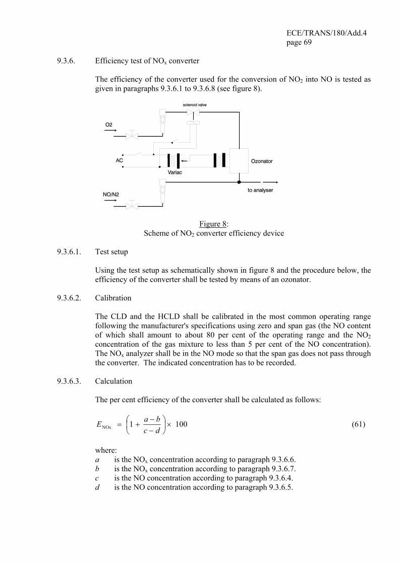
ECE/TRANS/180/Add.4 page 69
9.3.6. Efficiency test of NOx converter The efficiency of the converter used for the conversion of NO2 into NO is tested as
given in paragraphs 9.3.6.1 to 9.3.6.8 (see figure 8).
Figure 8: Scheme of NO2 converter efficiency device
9.3.6.1. Test setup Using the test setup as schematically shown in figure 8 and the procedure below, the
efficiency of the converter shall be tested by means of an ozonator. 9.3.6.2. Calibration The CLD and the HCLD shall be calibrated in the most common operating range
following the manufacturer's specifications using zero and span gas (the NO content of which shall amount to about 80 per cent of the operating range and the NO2 concentration of the gas mixture to less than 5 per cent of the NO concentration). The NOx analyzer shall be in the NO mode so that the span gas does not pass through the converter. The indicated concentration has to be recorded.
9.3.6.3. Calculation The per cent efficiency of the converter shall be calculated as follows:
1001NOx ×⎟⎠⎞
⎜⎝⎛
−−
+=dcbaE (61)
where: a is the NOx concentration according to paragraph 9.3.6.6. b is the NOx concentration according to paragraph 9.3.6.7. c is the NO concentration according to paragraph 9.3.6.4. d is the NO concentration according to paragraph 9.3.6.5.
ECE/TRANS/180/Add.4 page 70 9.3.6.4. Adding of oxygen Via a T-fitting, oxygen or zero air shall be added continuously to the gas flow until
the concentration indicated is about 20 per cent less than the indicated calibration concentration given in paragraph 9.3.6.2. (the analyzer is in the NO mode).
The indicated concentration (c) shall be recorded. The ozonator is kept deactivated
throughout the process. 9.3.6.5. Activation of the ozonator The ozonator shall be activated to generate enough ozone to bring the NO
concentration down to about 20 per cent (minimum 10 per cent) of the calibration concentration given in paragraph 9.3.6.2. The indicated concentration (d) shall be recorded (the analyzer is in the NO mode).
9.3.6.6. NOx mode The NO analyzer shall be switched to the NOx mode so that the gas mixture
(consisting of NO, NO2, O2 and N2) now passes through the converter. The indicated concentration (a) shall be recorded (the analyzer is in the NOx mode).
9.3.6.7. Deactivation of the ozonator The ozonator is now deactivated. The mixture of gases described in
paragraph 9.3.6.6. passes through the converter into the detector. The indicated concentration (b) shall be recorded (the analyzer is in the NOx mode).
9.3.6.8. NO mode Switched to NO mode with the ozonator deactivated, the flow of oxygen or synthetic
air shall be shut off. The NOx reading of the analyzer shall not deviate by more than ± 5 per cent from the value measured according to paragraph 9.3.6.2. (the analyzer is in the NO mode).
9.3.6.9. Test interval The efficiency of the converter shall be tested at least once per month. 9.3.6.10. Efficiency requirement The efficiency of the converter ENOx shall not be less than 95 per cent. If, with the analyzer in the most common range, the ozonator cannot give a reduction
from 80 per cent to 20 per cent according to paragraph 9.3.6.5., the highest range which will give the reduction shall be used.
ECE/TRANS/180/Add.4 page 71
9.3.7. Adjustment of the FID 9.3.7.1. Optimization of the detector response The FID shall be adjusted as specified by the instrument manufacturer. A propane in
air span gas shall be used to optimize the response on the most common operating range.
With the fuel and airflow rates set at the manufacturer's recommendations,
a 350 ± 75 ppm C span gas shall be introduced to the analyzer. The response at a given fuel flow shall be determined from the difference between the span gas response and the zero gas response. The fuel flow shall be incrementally adjusted above and below the manufacturer's specification. The span and zero response at these fuel flows shall be recorded. The difference between the span and zero response shall be plotted and the fuel flow adjusted to the rich side of the curve. This is the initial flow rate setting which may need further optimization depending on the results of the hydrocarbon response factors and the oxygen interference check according to paragraphs 9.3.7.2. and 9.3.7.3. If the oxygen interference or the hydrocarbon response factors do not meet the following specifications, the airflow shall be incrementally adjusted above and below the manufacturer's specifications, repeating paragraphs 9.3.7.2. and 9.3.7.3. for each flow.
The optimization may optionally be conducted using the procedures outlined in SAE
paper No. 770141. 9.3.7.2. Hydrocarbon response factors A linearity verification of the analyzer shall be performed using propane in air and
purified synthetic air according to paragraph 9.2.1.3. Response factors shall be determined when introducing an analyzer into service and
after major service intervals. The response factor (rh) for a particular hydrocarbon species is the ratio of the FID C1 reading to the gas concentration in the cylinder expressed by ppm C1.
The concentration of the test gas shall be at a level to give a response of
approximately 80 per cent of full scale. The concentration shall be known to an accuracy of ± 2 per cent in reference to a gravimetric standard expressed in volume. In addition, the gas cylinder shall be preconditioned for 24 hours at a temperature of 298 K ± 5 K (25 °C ± 5 °C).
The test gases to be used and the relative response factor ranges are as follows: (a) Methane and purified synthetic air 1.00 ≤ rh ≤ 1.15 (b) Propylene and purified synthetic air 0.90 ≤ rh ≤ 1.1 (c) Toluene and purified synthetic air 0.90 ≤ rh ≤ 1.1 These values are relative to a rh of 1 for propane and purified synthetic air.
ECE/TRANS/180/Add.4 page 72 9.3.7.3. Oxygen interference check For raw exhaust gas analyzers only, the oxygen interference check shall be
performed when introducing an analyzer into service and after major service intervals.
A measuring range shall be chosen where the oxygen interference check gases will
fall in the upper 50 per cent. The test shall be conducted with the oven temperature set as required. Oxygen interference check gas specifications are found in paragraph 9.3.3.4.
(a) The analyzer shall be set at zero. (b) The analyzer shall be spanned with the 0 per cent oxygen blend for positive
ignition engines. Compression ignition engine instruments shall be spanned with the 21 per cent oxygen blend.
(c) The zero response shall be rechecked. If it has changed by more than 0.5 per cent of full scale, steps (a) and (b) of this paragraph shall be repeated.
(d) The 5 per cent and 10 per cent oxygen interference check gases shall be introduced.
(e) The zero response shall be rechecked. If it has changed by more than ± 1 per cent of full scale, the test shall be repeated.
(f) The oxygen interference EO2 shall be calculated for each mixture in step (d) as follows:
EO2 = (cref,d - c) x 100 / cref,d (62) with the analyzer response being
c = dFS,
dm,
bm,
bFS,bref,
cc
ccc
××
(63)
where: cref,b is the reference HC concentration in step (b), ppm C cref,d is the reference HC concentration in step (d), ppm C cFS,b is the full scale HC concentration in step (b), ppm C cFS,d is the full scale HC concentration in step (d), ppm C cm,b is the measured HC concentration in step (b), ppm C cm,d is the measured HC concentration in step (d), ppm C (g) The oxygen interference EO2 shall be less than ± 1.5 per cent for all required
oxygen interference check gases prior to testing. (h) If the oxygen interference EO2 is greater than ± 1.5 per cent, corrective action
may be taken by incrementally adjusting the airflow above and below the manufacturer's specifications, the fuel flow and the sample flow.
(i) The oxygen interference shall be repeated for each new setting.

ECE/TRANS/180/Add.4 page 73
9.3.8. Efficiency of the non-methane cutter (NMC) The NMC is used for the removal of the non-methane hydrocarbons from the sample
gas by oxidizing all hydrocarbons except methane. Ideally, the conversion for methane is 0 per cent, and for the other hydrocarbons represented by ethane is 100 per cent. For the accurate measurement of NMHC, the two efficiencies shall be determined and used for the calculation of the NMHC emission mass flow rate (see paragraph 8.5.1.).
9.3.8.1. Methane Efficiency Methane calibration gas shall be flown through the FID with and without bypassing
the NMC and the two concentrations recorded. The efficiency shall be determined as follows:
cc
Ecutter) HC(w/o
r)HC(w/cutteM 1−= (64)
where: cHC(w/cutter) is the HC concentration with CH4 flowing through the NMC, ppm C cHC(w/o cutter) is the HC concentration with CH4 bypassing the NMC, ppm C 9.3.8.2. Ethane Efficiency Ethane calibration gas shall be flown through the FID with and without bypassing the
NMC and the two concentrations recorded. The efficiency shall be determined as follows:
cc
Ecutter) HC(w/o
r)HC(w/cutteE 1−= (65)
where: cHC(w/cutter) is the HC concentration with C2H6 flowing through the NMC, ppm C cHC(w/o cutter) is the HC concentration with C2H6 bypassing the NMC, ppm C 9.3.9. Interference effects Other gases than the one being analyzed can interfere with the reading in several
ways. Positive interference occurs in NDIR instruments where the interfering gas gives the same effect as the gas being measured, but to a lesser degree. Negative interference occurs in NDIR instruments by the interfering gas broadening the absorption band of the measured gas, and in CLD instruments by the interfering gas quenching the reaction. The interference checks in paragraphs 9.3.9.1. and 9.3.9.2. shall be performed prior to an analyzer's initial use and after major service intervals.
9.3.9.1. CO analyzer interference check Water and CO2 can interfere with the CO analyzer performance. Therefore, a CO2
span gas having a concentration of 80 to 100 per cent of full scale of the maximum

ECE/TRANS/180/Add.4 page 74
operating range used during testing shall be bubbled through water at room temperature and the analyzer response recorded. The analyzer response shall not be more than 1 per cent of full scale for ranges equal to or above 300 ppm or more than 3 ppm for ranges below 300 ppm.
9.3.9.2. NOx analyzer quench checks The two gases of concern for CLD (and HCLD) analyzers are CO2 and water vapour.
Quench responses to these gases are proportional to their concentrations, and therefore require test techniques to determine the quench at the highest expected concentrations experienced during testing.
9.3.9.2.1. CO2 quench check A CO2 span gas having a concentration of 80 to 100 per cent of full scale of the
maximum operating range shall be passed through the NDIR analyzer and the CO2 value recorded as A. It shall then be diluted approximately 50 per cent with NO span gas and passed through the NDIR and CLD, with the CO2 and NO values recorded as B and C, respectively. The CO2 shall then be shut off and only the NO span gas be passed through the (H)CLD and the NO value recorded as D.
The per cent quench shall be calculated as follows:
( )
( ) ( ) 1001CO2 ×⎥⎦
⎤⎢⎣
⎡⎟⎟⎠
⎞⎜⎜⎝
⎛×−×
×−=
BDADAC
E (66)
where: A is the undiluted CO2 concentration measured with NDIR, per cent B is the diluted CO2 concentration measured with NDIR, per cent C is the diluted NO concentration measured with (H)CLD, ppm D is the undiluted NO concentration measured with (H)CLD, ppm Alternative methods of diluting and quantifying of CO2 and NO span gas values such
as dynamic mixing/blending are permitted with the approval of the type approval or certification authority.
9.3.9.2.2. Water quench check This check applies to wet gas concentration measurements only. Calculation of
water quench shall consider dilution of the NO span gas with water vapour and scaling of water vapour concentration of the mixture to that expected during testing.
A NO span gas having a concentration of 80 per cent to 100 per cent of full scale of
the normal operating range shall be passed through the (H) CLD and the NO value recorded as D. The NO span gas shall then be bubbled through water at room temperature and passed through the (H) CLD and the NO value recorded as C. The water temperature shall be determined and recorded as F. The mixture's saturation
ECE/TRANS/180/Add.4 page 75
vapour pressure that corresponds to the bubbler water temperature (F) shall be determined and recorded as G.
The water vapour concentration (in per cent) of the mixture shall be calculated as
follows: H = 100 x (G / pb) (67) and recorded as H. The expected diluted NO span gas (in water vapour)
concentration shall be calculated as follows: De = D x ( 1- H / 100 ) (68) and recorded as De. For diesel exhaust, the maximum exhaust water vapour
concentration (in per cent) expected during testing shall be estimated, under the assumption of a fuel H/C ratio of 1.8/1, from the maximum CO2 concentration in the exhaust gas A as follows:
Hm = 0.9 x A (69) and recorded as Hm The per cent water quench shall be calculated as follows: EH2O = 100 x ( ( De - C ) / De) x (Hm / H) (70) where: De is the expected diluted NO concentration, ppm C is the measured diluted NO concentration, ppm Hm is the maximum water vapour concentration, per cent H is the actual water vapour concentration, per cent
ECE/TRANS/180/Add.4 page 76 9.3.9.2.3. Maximum allowable quench (a) For raw measurement: (i) CO2 quench according to paragraph 9.3.9.2.1.: 2 per cent of full scale (ii) water quench according to paragraph 9.3.9.2.2.: 3 per cent of full scale (b) For dilute measurement: (i) 2 per cent combined CO2 and water quench. 9.3.9.2.4. Efficiency of the cooling bath For dry CLD analyzers, it shall be demonstrated that for the highest expected water
vapour concentration Hm (see paragraph 9.3.9.2.2.), the water removal technique maintains CLD humidity at ≤ 5 g water/kg dry air (or about 0.008 per cent H2O), which is 100 per cent relative humidity at 3.9 °C and 101.3 kPa. This humidity specification is also equivalent to about 25 per cent relative humidity at 25 °C and 101.3 kPa. This may be demonstrated by measuring the temperature at the outlet of a thermal dehumidifier, or by measuring humidity at a point just upstream of the CLD. Humidity of the CLD exhaust might also be measured as long as the only flow into the CLD is the flow from the dehumidifier.
9.4. Particulate measurement and sampling system 9.4.1. General specifications To determine the mass of the particulates, a particulate sampling system, a
particulate sampling filter, a microgram balance, and a temperature and humidity controlled weighing chamber, are required. The particulate sampling system shall be designed to ensure a representative sample of the particulates proportional to the exhaust flow.
9.4.2. Particulate sampling filters The diluted exhaust shall be sampled by a filter that meets the requirements of
paragraphs 9.4.2.1. to 9.4.2.3. during the test sequence. Selection of the options in paragraphs 9.4.2.1. and 9.4.2.2. shall be decided by the Contracting Parties.
9.4.2.1. Filter specification All filter types shall have a 0.3 µm DOP (di-octylphthalate) collection efficiency of
at least 99 per cent. The filter material shall be either: (a) fluorocarbon (PTFE) coated glass fiber, or (b) fluorocarbon (PTFE) membrane.
ECE/TRANS/180/Add.4 page 77
9.4.2.2. Filter size The filter size shall be either: (a) 47 mm diameter or (b) 70 mm diameter. 9.4.2.3. Filter face velocity The face velocity through the filter shall not exceed 1 m/s. The pressure drop
increase between the beginning and the end of the test shall not exceed 25 kPa. 9.4.3. Weighing chamber and analytical balance specifications 9.4.3.1. Weighing chamber conditions The temperature of the chamber (or room) in which the particulate filters are
conditioned and weighed shall be maintained to within 295 K ± 3 K (22 °C ± 3 °C) during all filter conditioning and weighing. The humidity shall be maintained to a dew point of 282.5 K ± 3 K (9.5 °C ± 3 °C) and a relative humidity of 45 per cent ± 8 per cent. For sensitive balances, it is recommended that the tolerance for the weighing chamber room air temperature and the dew point be ± 1 K.
9.4.3.2. Reference filter weighing The chamber (or room) environment shall be free of any ambient contaminants (such
as dust) that would settle on the particulate filters during their stabilization. Disturbances to weighing room specifications as outlined in paragraph 9.4.3.1. will be allowed if the duration of the disturbances does not exceed 30 minutes. The weighing room shall meet the required specifications prior to personal entrance into the weighing room. At least two unused reference filters shall be weighed within 12 hours of, but preferably at the same time as the sample filter weighing. They shall be the same size and material as the sample filters.
If the average weight of the reference filters changes between sample filter
weighings by more than 10 µg, all sample filters shall be discarded and the emissions test repeated.
9.4.3.3. Analytical balance The analytical balance used to determine the filter weight shall meet the linearity
verification criterion of paragraph 9.2., table 6. This implies a precision (standard deviation) of at least 2 µg and a resolution of at least 1 µg (1 digit = 1 µg).
ECE/TRANS/180/Add.4 page 78 9.4.3.4. Elimination of static electricity effects The filter shall be neutralized prior to weighing, e.g. by a Polonium neutralizer or a
device of similar effect. 9.4.3.5. Buoyancy correction The sampling filter shall be corrected for its buoyancy in air. The buoyancy
correction depends on sampling filter density, air density and the density of the balance calibration weight, and does not account for the buoyancy of the PM itself.
If the density of the filter material is not known, the following densities shall be
used: (a) teflon coated glass fiber filter: 2,300 kg/m3 (b) teflon membrane filter: 2,144 kg/m3 (c) teflon membrane filter with polymethylpentene support ring: 920 kg/m3 For stainless steel calibration weights, a density of 8,000 kg/m3 shall be used. If the
material of the calibration weight is different, its density must be known. The following equation shall be used:
⎟⎟⎟⎟
⎠
⎞
⎜⎜⎜⎜
⎝
⎛ −×=
f
a
w
a
uncorf
-1
1
ρρρρ
mm (71)
with
a
ba 8.3144
836.28T
p×
×=ρ (72)
where: muncor is the uncorrected particulate sample mass, mg ρa is the density of the air, kg/m3 ρw is the density of balance calibration weight, kg/m3 ρf is the density of the particulate sampling filter, kg/m3 pb is the total atmospheric pressure, kPa Ta is the air temperature in the balance environment, K 28.836 is the molar mass of the air at reference humidity (9.5 K), g/mol 8.3144 is the molar gas constant
ECE/TRANS/180/Add.4 page 79
9.4.4. Specifications for differential flow measurement (partial flow dilution only) For partial flow dilution systems, the accuracy of the sample flow qmp is of special
concern, if not measured directly, but determined by differential flow measurement: qmp = qmdew – qmdw (73) In this case, the maximum error of the difference shall be such that the accuracy of
qmp is within ±5 per cent when the dilution ratio is less than 15. It can be calculated by taking root-mean-square of the errors of each instrument.
Acceptable accuracies of qmp can be obtained by either of the following methods: (a) The absolute accuracies of qmdew and qmdw are ± 0.2 per cent which guarantees
an accuracy of qmp of ≤ 5 per cent at a dilution ratio of 15. However, greater errors will occur at higher dilution ratios.
(b) Calibration of qmdw relative to qmdew is carried out such that the same accuracies for qmp as in (a) are obtained. For details see paragraph 9.4.6.2.
(c) The accuracy of qmp is determined indirectly from the accuracy of the dilution ratio as determined by a tracer gas, e.g. CO2. Accuracies equivalent to method (a) for qmp are required.
(d) The absolute accuracy of qmdew and qmdw is within ± 2 per cent of full scale, the maximum error of the difference between qmdew and qmdw is within 0.2 per cent, and the linearity error is within ± 0.2 per cent of the highest qmdew observed during the test.
9.4.5. Additional specifications All parts of the dilution system and the sampling system from the exhaust pipe up to
the filter holder, which are in contact with raw and diluted exhaust gas, shall be designed to minimize deposition or alteration of the particulates. All parts shall be made of electrically conductive materials that do not react with exhaust gas components, and shall be electrically grounded to prevent electrostatic effects.
9.4.6. Calibration of the flow measurement instrumentation 9.4.6.1. General specifications Each flowmeter used in a particulate sampling and partial flow dilution system shall
be subjected to the linearity verification, as described in paragraph 9.2.1., as often as necessary to fulfil the accuracy requirements of this gtr. For the flow reference values, an accurate flowmeter traceable to international and/or national standards shall be used.
ECE/TRANS/180/Add.4 page 80 9.4.6.2. Calibration of differential flow measurement (partial flow dilution only) The flowmeter or the flow measurement instrumentation shall be calibrated in one of
the following procedures, such that the probe flow qmp into the tunnel shall fulfil the accuracy requirements of paragraph 9.4.4.:
(a) The flowmeter for qmdw shall be connected in series to the flowmeter for qmdew,
the difference between the two flowmeters shall be calibrated for at least 5 set points with flow values equally spaced between the lowest qmdw value used during the test and the value of qmdew used during the test. The dilution tunnel may be bypassed.
(b) A calibrated flow device shall be connected in series to the flowmeter for qmdew
and the accuracy shall be checked for the value used for the test. The calibrated flow device shall be connected in series to the flowmeter for qmdw, and the accuracy shall be checked for at least 5 settings corresponding to dilution ratio between 3 and 50, relative to qmdew used during the test.
(c) The transfer tube (TT) shall be disconnected from the exhaust, and a calibrated
flow-measuring device with a suitable range to measure qmp shall be connected to the transfer tube. qmdew shall be set to the value used during the test, and qmdw shall be sequentially set to at least 5 values corresponding to dilution ratios between 3 and 50. Alternatively, a special calibration flow path may be provided, in which the tunnel is bypassed, but the total and dilution airflow through the corresponding meters as in the actual test.
(d) A tracer gas shall be fed into the exhaust transfer tube TT. This tracer gas may
be a component of the exhaust gas, like CO2 or NOx. After dilution in the tunnel the tracer gas component shall be measured. This shall be carried out for 5 dilution ratios between 3 and 50. The accuracy of the sample flow shall be determined from the dilution ratio rd:
qmp = qmdew /rd (74)
The accuracies of the gas analyzers shall be taken into account to guarantee the accuracy of qmp.
9.4.7. Special requirements for the partial flow dilution system 9.4.7.1. Carbon flow check A carbon flow check using actual exhaust is strongly recommended for detecting
measurement and control problems and verifying the proper operation of the partial flow system. The carbon flow check should be run at least each time a new engine is installed, or something significant is changed in the test cell configuration.
ECE/TRANS/180/Add.4 page 81
The engine shall be operated at peak torque load and speed or any other steady state mode that produces 5 per cent or more of CO2. The partial flow sampling system shall be operated with a dilution factor of about 15 to 1.
If a carbon flow check is conducted, the procedure given in Annex 5 shall be applied.
The carbon flow rates shall be calculated according to equations 80 to 82 in Annex 5. All carbon flow rates should agree to within 3 per cent.
9.4.7.2. Pre-test check A pre-test check shall be performed within 2 hours before the test run in the
following way. The accuracy of the flowmeters shall be checked by the same method as used for
calibration (see paragraph 9.4.6.2.) for at least two points, including flow values of qmdw that correspond to dilution ratios between 5 and 15 for the qmdew value used during the test.
If it can be demonstrated by records of the calibration procedure under
paragraph 9.4.6.2. that the flowmeter calibration is stable over a longer period of time, the pre-test check may be omitted.
9.4.7.3. Determination of the transformation time The system settings for the transformation time evaluation shall be exactly the same
as during measurement of the test run. The transformation time shall be determined by the following method.
An independent reference flowmeter with a measurement range appropriate for the
probe flow shall be put in series with and closely coupled to the probe. This flowmeter shall have a transformation time of less than 100 ms for the flow step size used in the response time measurement, with flow restriction sufficiently low as to not affect the dynamic performance of the partial flow dilution system, and consistent with good engineering practice.
A step change shall be introduced to the exhaust flow (or airflow if exhaust flow is
calculated) input of the partial flow dilution system, from a low flow to at least 90 per cent of full scale. The trigger for the step change shall be the same one used to start the look-ahead control in actual testing. The exhaust flow step stimulus and the flowmeter response shall be recorded at a sample rate of at least 10 Hz.
From this data, the transformation time shall be determined for the partial flow
dilution system, which is the time from the initiation of the step stimulus to the 50 per cent point of the flowmeter response. In a similar manner, the transformation times of the qmp signal of the partial flow dilution system and of the qmew,i signal of the exhaust flowmeter shall be determined. These signals are used in the regression checks performed after each test (see paragraph 8.3.3.3.)
ECE/TRANS/180/Add.4 page 82 The calculation shall be repeated for at least 5 rise and fall stimuli, and the results
shall be averaged. The internal transformation time (< 100 ms) of the reference flowmeter shall be subtracted from this value. This is the "look-ahead" value of the partial flow dilution system, which shall be applied in accordance with paragraph 8.3.3.3.
9.5. Calibration of the CVS system 9.5.1. General The CVS system shall be calibrated by using an accurate flowmeter and a restricting
device. The flow through the system shall be measured at different restriction settings, and the control parameters of the system shall be measured and related to the flow.
Various types of flowmeters may be used, e.g. calibrated venturi, calibrated laminar
flowmeter, calibrated turbine meter. 9.5.2. Calibration of the positive displacement pump (PDP) All the parameters related to the pump shall be simultaneously measured along with
the parameters related to a calibration venturi which is connected in series with the pump. The calculated flow rate (in m3/s at pump inlet, absolute pressure and temperature) shall be plotted versus a correlation function which is the value of a specific combination of pump parameters. The linear equation which relates the pump flow and the correlation function shall be determined. If a CVS has a multiple speed drive, the calibration shall be performed for each range used.
Temperature stability shall be maintained during calibration. Leaks in all the connections and ducting between the calibration venturi and the CVS
pump shall be maintained lower than 0.3 per cent of the lowest flow point (highest restriction and lowest PDP speed point).
9.5.2.1. Data analysis The airflow rate (qvCVS) at each restriction setting (minimum 6 settings) shall be
calculated in standard m3/s from the flowmeter data using the manufacturer's prescribed method. The airflow rate shall then be converted to pump flow (V0) in m3/rev at absolute pump inlet temperature and pressure as follows:
p
CVS0
3.101273 pT
nqV v ××= (75)
where: qvCVS is the airflow rate at standard conditions (101.3 kPa, 273 K), m3/s

ECE/TRANS/180/Add.4 page 83
T is the temperature at pump inlet, K pp is the absolute pressure at pump inlet, kPa n is the pump speed, rev/s To account for the interaction of pressure variations at the pump and the pump slip
rate, the correlation function (X0) between pump speed, pressure differential from pump inlet to pump outlet and absolute pump outlet pressure shall be calculated as follows:
p
p0
1pp
nX
Δ×= (76)
where: Δpp is the pressure differential from pump inlet to pump outlet, kPa pp is the absolute outlet pressure at pump outlet, kPa A linear least-square fit shall be performed to generate the calibration equation as
follows: 000 XmDV ×−= (77) D0 and m are the intercept and slope, respectively, describing the regression lines. For a CVS system with multiple speeds, the calibration curves generated for the
different pump flow ranges shall be approximately parallel, and the intercept values (D0) shall increase as the pump flow range decreases.
The calculated values from the equation shall be within ± 0.5 per cent of the
measured value of V0. Values of m will vary from one pump to another. Particulate influx over time will cause the pump slip to decrease, as reflected by lower values for m. Therefore, calibration shall be performed at pump start-up, after major maintenance, and if the total system verification indicates a change of the slip rate.
9.5.3. Calibration of the critical flow venturi (CFV) Calibration of the CFV is based upon the flow equation for a critical venturi. Gas
flow is a function of venturi inlet pressure and temperature. To determine the range of critical flow, Kv shall be plotted as a function of venturi
inlet pressure. For critical (choked) flow, Kv will have a relatively constant value. As pressure decreases (vacuum increases), the venturi becomes unchoked and Kv decreases, which indicates that the CFV is operated outside the permissible range.
ECE/TRANS/180/Add.4 page 84 9.5.3.1. Data analysis The airflow rate (qvCVS) at each restriction setting (minimum 8 settings) shall be
calculated in standard m3/s from the flowmeter data using the manufacturer's prescribed method. The calibration coefficient shall be calculated from the calibration data for each setting as follows:
p
CVS
pTqK v
v×
= (78)
where: qvCVS is the airflow rate at standard conditions (101.3 kPa, 273 K), m3/s T is the temperature at the venturi inlet, K pp is the absolute pressure at venturi inlet, kPa The average KV and the standard deviation shall be calculated. The standard
deviation shall not exceed ± 0.3 per cent of the average KV. 9.5.4. Calibration of the subsonic venturi (SSV) Calibration of the SSV is based upon the flow equation for a subsonic venturi. Gas
flow is a function of inlet pressure and temperature, pressure drop between the SSV inlet and throat, as shown in equation 43 (see paragraph 8.4.1.4.).
9.5.4.1. Data analysis The airflow rate (QSSV) at each restriction setting (minimum 16 settings) shall be
calculated in standard m3/s from the flowmeter data using the manufacturer's prescribed method. The discharge coefficient shall be calculated from the calibration data for each setting as follows:
( )⎥⎥⎦
⎤
⎢⎢⎣
⎡
⎟⎟⎠
⎞⎜⎜⎝
⎛
×−×−×××
=
1.4286p
4D
1.7143p
1.4286pp
2V
SSVd
rr11rr
T1pd
QC (79)
where: QSSV is the airflow rate at standard conditions (101.3 kPa, 273 K), m3/s T is the temperature at the venturi inlet, K dV is the diameter of the SSV throat, m
rp is the ratio of the SSV throat to inlet absolute static pressure = p
1ppΔ
−
rD is the ratio of the SSV throat diameter, dV, to the inlet pipe inner diameter D
ECE/TRANS/180/Add.4 page 85
To determine the range of subsonic flow, Cd shall be plotted as a function of Reynolds number Re, at the SSV throat. The Re at the SSV throat shall be calculated with the following equation:
μ×
×=V
SSV1Re
dQ
A (80)
with
T
T+
×=
Sb 5.1
μ (81)
where: A1 is 25.55152 in SI units of ⎟
⎠⎞
⎜⎝⎛
⎟⎠⎞
⎜⎝⎛
⎟⎠⎞
⎜⎝⎛
mmm
smmin1
3
QSSV is the airflow rate at standard conditions (101.3 kPa, 273 K), m3/s dV is the diameter of the SSV throat, m μ is the absolute or dynamic viscosity of the gas, kg/ms b is 1.458 x 10⁶ (empirical constant), kg/ms K0.5
S is 110.4 (empirical constant), K Because QSSV is an input to the Re equation, the calculations must be started with an
initial guess for QSSV or Cd of the calibration venturi, and repeated until QSSV converges. The convergence method shall be accurate to 0.1 per cent of point or better.
For a minimum of sixteen points in the region of subsonic flow, the calculated values
of Cd from the resulting calibration curve fit equation must be within ± 0.5 per cent of the measured Cd for each calibration point.
9.5.5. Total system verification The total accuracy of the CVS sampling system and analytical system shall be
determined by introducing a known mass of a pollutant gas into the system while it is being operated in the normal manner. The pollutant is analyzed, and the mass calculated according to paragraph 8.4.2.4. except in the case of propane where a u factor of 0.000472 is used in place of 0.000480 for HC. Either of the following two techniques shall be used.
9.5.5.1. Metering with a critical flow orifice A known quantity of pure gas (carbon monoxide or propane) shall be fed into the
CVS system through a calibrated critical orifice. If the inlet pressure is high enough, the flow rate, which is adjusted by means of the critical flow orifice, is independent of the orifice outlet pressure (critical flow). The CVS system shall be operated as in a normal exhaust emission test for about 5 to 10 minutes. A gas sample shall be

ECE/TRANS/180/Add.4 page 86
analyzed with the usual equipment (sampling bag or integrating method), and the mass of the gas calculated. The mass so determined shall be within ± 3 per cent of the known mass of the gas injected.
9.5.5.2. Metering by means of a gravimetric technique The mass of a small cylinder filled with carbon monoxide or propane shall be
determined with a precision of ± 0.01 g. For about 5 to 10 minutes, the CVS system shall be operated as in a normal exhaust emission test, while carbon monoxide or propane is injected into the system. The quantity of pure gas discharged shall be determined by means of differential weighing. A gas sample shall be analyzed with the usual equipment (sampling bag or integrating method), and the mass of the gas calculated. The mass so determined shall be within ± 3 per cent of the known mass of the gas injected.
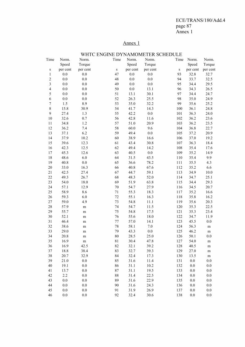
ECE/TRANS/180/Add.4 page 87 Annex 1
Annex 1
WHTC ENGINE DYNAMOMETER SCHEDULE Time Norm. Norm. Time Norm. Norm. Time Norm. Norm.
Speed Torque Speed Torque Speed Torque s per cent per cent s per cent per cent s per cent per cent 1 0.0 0.0 47 0.0 0.0 93 32.8 32.7 2 0.0 0.0 48 0.0 0.0 94 33.7 32.5 3 0.0 0.0 49 0.0 0.0 95 34.4 29.5 4 0.0 0.0 50 0.0 13.1 96 34.3 26.5 5 0.0 0.0 51 13.1 30.1 97 34.4 24.7 6 0.0 0.0 52 26.3 25.5 98 35.0 24.9 7 1.5 8.9 53 35.0 32.2 99 35.6 25.2 8 15.8 30.9 54 41.7 14.3 100 36.1 24.8 9 27.4 1.3 55 42.2 0.0 101 36.3 24.0 10 32.6 0.7 56 42.8 11.6 102 36.2 23.6 11 34.8 1.2 57 51.0 20.9 103 36.2 23.5 12 36.2 7.4 58 60.0 9.6 104 36.8 22.7 13 37.1 6.2 59 49.4 0.0 105 37.2 20.9 14 37.9 10.2 60 38.9 16.6 106 37.0 19.2 15 39.6 12.3 61 43.4 30.8 107 36.3 18.4 16 42.3 12.5 62 49.4 14.2 108 35.4 17.6 17 45.3 12.6 63 40.5 0.0 109 35.2 14.9 18 48.6 6.0 64 31.5 43.5 110 35.4 9.9 19 40.8 0.0 65 36.6 78.2 111 35.5 4.3 20 33.0 16.3 66 40.8 67.6 112 35.2 6.6 21 42.5 27.4 67 44.7 59.1 113 34.9 10.0 22 49.3 26.7 68 48.3 52.0 114 34.7 25.1 23 54.0 18.0 69 51.9 63.8 115 34.4 29.3 24 57.1 12.9 70 54.7 27.9 116 34.5 20.7 25 58.9 8.6 71 55.3 18.3 117 35.2 16.6 26 59.3 6.0 72 55.1 16.3 118 35.8 16.2 27 59.0 4.9 73 54.8 11.1 119 35.6 20.3 28 57.9 m 74 54.7 11.5 120 35.3 22.5 29 55.7 m 75 54.8 17.5 121 35.3 23.4 30 52.1 m 76 55.6 18.0 122 34.7 11.9 31 46.4 m 77 57.0 14.1 123 45.5 0.0 32 38.6 m 78 58.1 7.0 124 56.3 m 33 29.0 m 79 43.3 0.0 125 46.2 m 34 20.8 m 80 28.5 25.0 126 50.1 0.0 35 16.9 m 81 30.4 47.8 127 54.0 m 36 16.9 42.5 82 32.1 39.2 128 40.5 m 37 18.8 38.4 83 32.7 39.3 129 27.0 m 38 20.7 32.9 84 32.4 17.3 130 13.5 m 39 21.0 0.0 85 31.6 11.4 131 0.0 0.0 40 19.1 0.0 86 31.1 10.2 132 0.0 0.0 41 13.7 0.0 87 31.1 19.5 133 0.0 0.0 42 2.2 0.0 88 31.4 22.5 134 0.0 0.0 43 0.0 0.0 89 31.6 22.9 135 0.0 0.0 44 0.0 0.0 90 31.6 24.3 136 0.0 0.0 45 0.0 0.0 91 31.9 26.9 137 0.0 0.0 46 0.0 0.0 92 32.4 30.6 138 0.0 0.0
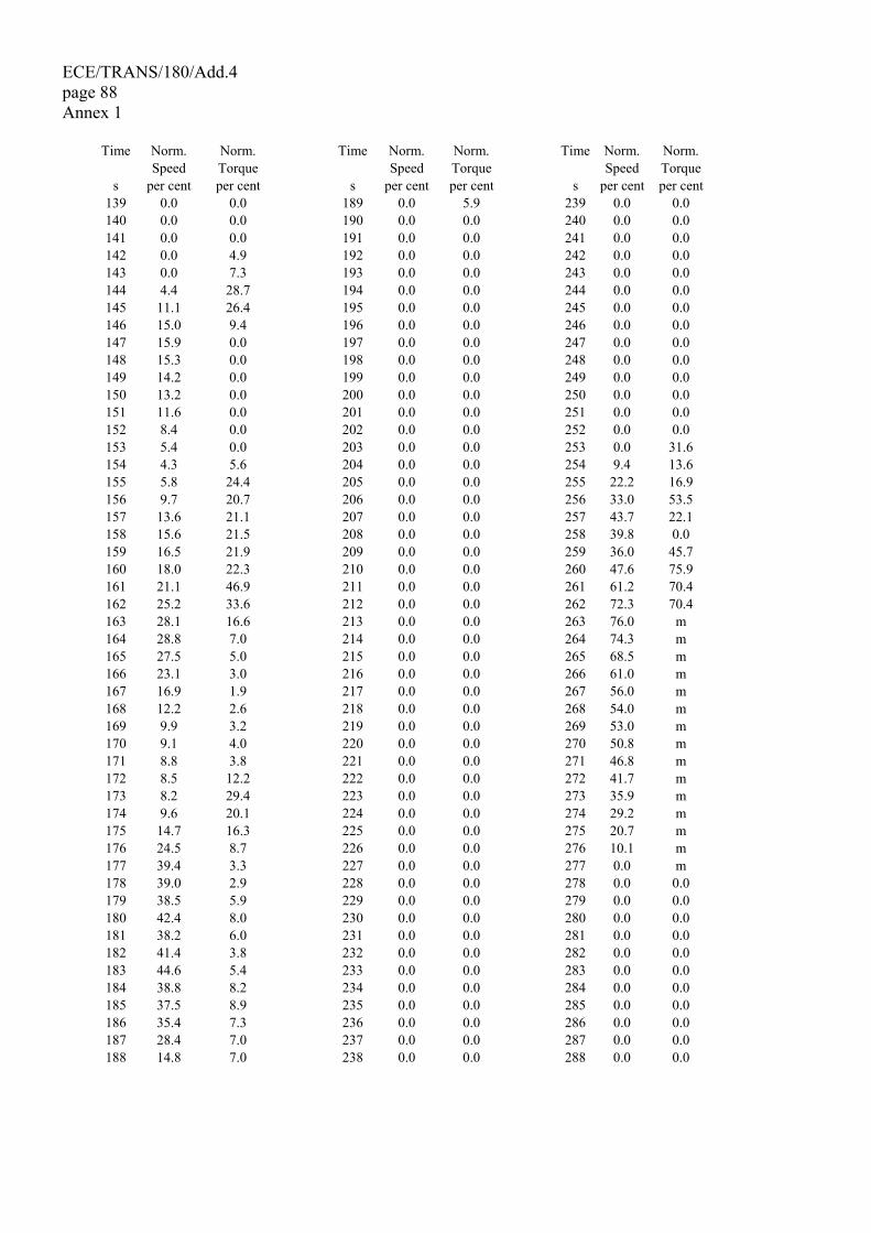
ECE/TRANS/180/Add.4 page 88 Annex 1
Time Norm. Norm. Time Norm. Norm. Time Norm. Norm. Speed Torque Speed Torque Speed Torque s per cent per cent s per cent per cent s per cent per cent
139 0.0 0.0 189 0.0 5.9 239 0.0 0.0 140 0.0 0.0 190 0.0 0.0 240 0.0 0.0 141 0.0 0.0 191 0.0 0.0 241 0.0 0.0 142 0.0 4.9 192 0.0 0.0 242 0.0 0.0 143 0.0 7.3 193 0.0 0.0 243 0.0 0.0 144 4.4 28.7 194 0.0 0.0 244 0.0 0.0 145 11.1 26.4 195 0.0 0.0 245 0.0 0.0 146 15.0 9.4 196 0.0 0.0 246 0.0 0.0 147 15.9 0.0 197 0.0 0.0 247 0.0 0.0 148 15.3 0.0 198 0.0 0.0 248 0.0 0.0 149 14.2 0.0 199 0.0 0.0 249 0.0 0.0 150 13.2 0.0 200 0.0 0.0 250 0.0 0.0 151 11.6 0.0 201 0.0 0.0 251 0.0 0.0 152 8.4 0.0 202 0.0 0.0 252 0.0 0.0 153 5.4 0.0 203 0.0 0.0 253 0.0 31.6 154 4.3 5.6 204 0.0 0.0 254 9.4 13.6 155 5.8 24.4 205 0.0 0.0 255 22.2 16.9 156 9.7 20.7 206 0.0 0.0 256 33.0 53.5 157 13.6 21.1 207 0.0 0.0 257 43.7 22.1 158 15.6 21.5 208 0.0 0.0 258 39.8 0.0 159 16.5 21.9 209 0.0 0.0 259 36.0 45.7 160 18.0 22.3 210 0.0 0.0 260 47.6 75.9 161 21.1 46.9 211 0.0 0.0 261 61.2 70.4 162 25.2 33.6 212 0.0 0.0 262 72.3 70.4 163 28.1 16.6 213 0.0 0.0 263 76.0 m 164 28.8 7.0 214 0.0 0.0 264 74.3 m 165 27.5 5.0 215 0.0 0.0 265 68.5 m 166 23.1 3.0 216 0.0 0.0 266 61.0 m 167 16.9 1.9 217 0.0 0.0 267 56.0 m 168 12.2 2.6 218 0.0 0.0 268 54.0 m 169 9.9 3.2 219 0.0 0.0 269 53.0 m 170 9.1 4.0 220 0.0 0.0 270 50.8 m 171 8.8 3.8 221 0.0 0.0 271 46.8 m 172 8.5 12.2 222 0.0 0.0 272 41.7 m 173 8.2 29.4 223 0.0 0.0 273 35.9 m 174 9.6 20.1 224 0.0 0.0 274 29.2 m 175 14.7 16.3 225 0.0 0.0 275 20.7 m 176 24.5 8.7 226 0.0 0.0 276 10.1 m 177 39.4 3.3 227 0.0 0.0 277 0.0 m 178 39.0 2.9 228 0.0 0.0 278 0.0 0.0 179 38.5 5.9 229 0.0 0.0 279 0.0 0.0 180 42.4 8.0 230 0.0 0.0 280 0.0 0.0 181 38.2 6.0 231 0.0 0.0 281 0.0 0.0 182 41.4 3.8 232 0.0 0.0 282 0.0 0.0 183 44.6 5.4 233 0.0 0.0 283 0.0 0.0 184 38.8 8.2 234 0.0 0.0 284 0.0 0.0 185 37.5 8.9 235 0.0 0.0 285 0.0 0.0 186 35.4 7.3 236 0.0 0.0 286 0.0 0.0 187 28.4 7.0 237 0.0 0.0 287 0.0 0.0 188 14.8 7.0 238 0.0 0.0 288 0.0 0.0
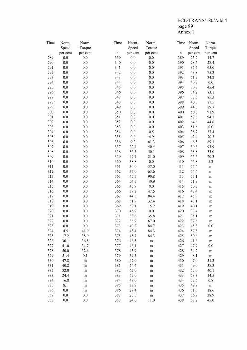
ECE/TRANS/180/Add.4 page 89 Annex 1
Time Norm. Norm. Time Norm. Norm. Time Norm. Norm. Speed Torque Speed Torque Speed Torque s per cent per cent s per cent per cent s per cent per cent
289 0.0 0.0 339 0.0 0.0 389 25.2 14.7 290 0.0 0.0 340 0.0 0.0 390 28.6 28.4 291 0.0 0.0 341 0.0 0.0 391 35.5 65.0 292 0.0 0.0 342 0.0 0.0 392 43.8 75.3 293 0.0 0.0 343 0.0 0.0 393 51.2 34.2 294 0.0 0.0 344 0.0 0.0 394 40.7 0.0 295 0.0 0.0 345 0.0 0.0 395 30.3 45.4 296 0.0 0.0 346 0.0 0.0 396 34.2 83.1 297 0.0 0.0 347 0.0 0.0 397 37.6 85.3 298 0.0 0.0 348 0.0 0.0 398 40.8 87.5 299 0.0 0.0 349 0.0 0.0 399 44.8 89.7 300 0.0 0.0 350 0.0 0.0 400 50.6 91.9 301 0.0 0.0 351 0.0 0.0 401 57.6 94.1 302 0.0 0.0 352 0.0 0.0 402 64.6 44.6 303 0.0 0.0 353 0.0 0.0 403 51.6 0.0 304 0.0 0.0 354 0.0 0.5 404 38.7 37.4 305 0.0 0.0 355 0.0 4.9 405 42.4 70.3 306 0.0 0.0 356 9.2 61.3 406 46.5 89.1 307 0.0 0.0 357 22.4 40.4 407 50.6 93.9 308 0.0 0.0 358 36.5 50.1 408 53.8 33.0 309 0.0 0.0 359 47.7 21.0 409 55.5 20.3 310 0.0 0.0 360 38.8 0.0 410 55.8 5.2 311 0.0 0.0 361 30.0 37.0 411 55.4 m 312 0.0 0.0 362 37.0 63.6 412 54.4 m 313 0.0 0.0 363 45.5 90.8 413 53.1 m 314 0.0 0.0 364 54.5 40.9 414 51.8 m 315 0.0 0.0 365 45.9 0.0 415 50.3 m 316 0.0 0.0 366 37.2 47.5 416 48.4 m 317 0.0 0.0 367 44.5 84.4 417 45.9 m 318 0.0 0.0 368 51.7 32.4 418 43.1 m 319 0.0 0.0 369 58.1 15.2 419 40.1 m 320 0.0 0.0 370 45.9 0.0 420 37.4 m 321 0.0 0.0 371 33.6 35.8 421 35.1 m 322 0.0 0.0 372 36.9 67.0 422 32.8 m 323 0.0 0.0 373 40.2 84.7 423 45.3 0.0 324 4.5 41.0 374 43.4 84.3 424 57.8 m 325 17.2 38.9 375 45.7 84.3 425 50.6 m 326 30.1 36.8 376 46.5 m 426 41.6 m 327 41.0 34.7 377 46.1 m 427 47.9 0.0 328 50.0 32.6 378 43.9 m 428 54.2 m 329 51.4 0.1 379 39.3 m 429 48.1 m 330 47.8 m 380 47.0 m 430 47.0 31.3 331 40.2 m 381 54.6 m 431 49.0 38.3 332 32.0 m 382 62.0 m 432 52.0 40.1 333 24.4 m 383 52.0 m 433 53.3 14.5 334 16.8 m 384 43.0 m 434 52.6 0.8 335 8.1 m 385 33.9 m 435 49.8 m 336 0.0 m 386 28.4 m 436 51.0 18.6 337 0.0 0.0 387 25.5 m 437 56.9 38.9 338 0.0 0.0 388 24.6 11.0 438 67.2 45.0
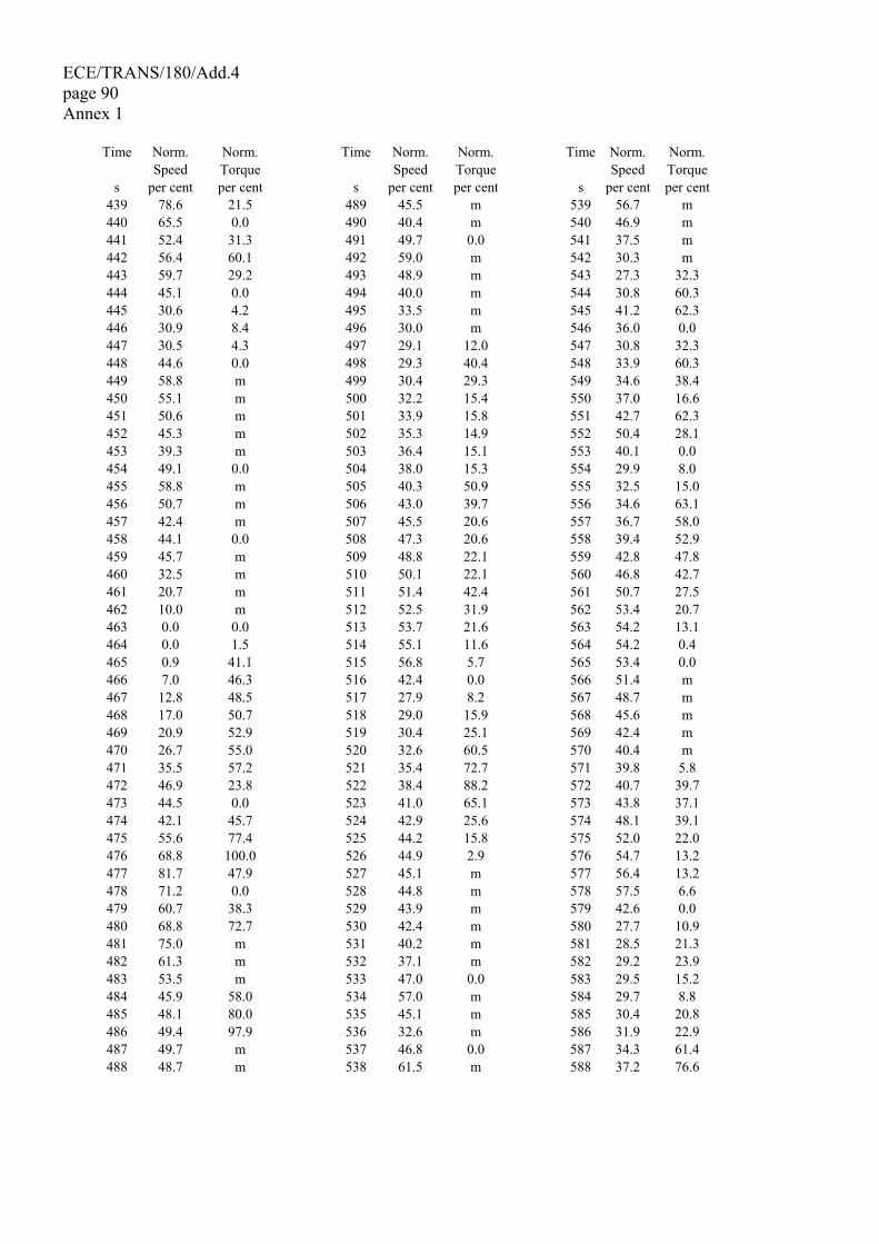
ECE/TRANS/180/Add.4 page 90 Annex 1
Time Norm. Norm. Time Norm. Norm. Time Norm. Norm. Speed Torque Speed Torque Speed Torque s per cent per cent s per cent per cent s per cent per cent
439 78.6 21.5 489 45.5 m 539 56.7 m 440 65.5 0.0 490 40.4 m 540 46.9 m 441 52.4 31.3 491 49.7 0.0 541 37.5 m 442 56.4 60.1 492 59.0 m 542 30.3 m 443 59.7 29.2 493 48.9 m 543 27.3 32.3 444 45.1 0.0 494 40.0 m 544 30.8 60.3 445 30.6 4.2 495 33.5 m 545 41.2 62.3 446 30.9 8.4 496 30.0 m 546 36.0 0.0 447 30.5 4.3 497 29.1 12.0 547 30.8 32.3 448 44.6 0.0 498 29.3 40.4 548 33.9 60.3 449 58.8 m 499 30.4 29.3 549 34.6 38.4 450 55.1 m 500 32.2 15.4 550 37.0 16.6 451 50.6 m 501 33.9 15.8 551 42.7 62.3 452 45.3 m 502 35.3 14.9 552 50.4 28.1 453 39.3 m 503 36.4 15.1 553 40.1 0.0 454 49.1 0.0 504 38.0 15.3 554 29.9 8.0 455 58.8 m 505 40.3 50.9 555 32.5 15.0 456 50.7 m 506 43.0 39.7 556 34.6 63.1 457 42.4 m 507 45.5 20.6 557 36.7 58.0 458 44.1 0.0 508 47.3 20.6 558 39.4 52.9 459 45.7 m 509 48.8 22.1 559 42.8 47.8 460 32.5 m 510 50.1 22.1 560 46.8 42.7 461 20.7 m 511 51.4 42.4 561 50.7 27.5 462 10.0 m 512 52.5 31.9 562 53.4 20.7 463 0.0 0.0 513 53.7 21.6 563 54.2 13.1 464 0.0 1.5 514 55.1 11.6 564 54.2 0.4 465 0.9 41.1 515 56.8 5.7 565 53.4 0.0 466 7.0 46.3 516 42.4 0.0 566 51.4 m 467 12.8 48.5 517 27.9 8.2 567 48.7 m 468 17.0 50.7 518 29.0 15.9 568 45.6 m 469 20.9 52.9 519 30.4 25.1 569 42.4 m 470 26.7 55.0 520 32.6 60.5 570 40.4 m 471 35.5 57.2 521 35.4 72.7 571 39.8 5.8 472 46.9 23.8 522 38.4 88.2 572 40.7 39.7 473 44.5 0.0 523 41.0 65.1 573 43.8 37.1 474 42.1 45.7 524 42.9 25.6 574 48.1 39.1 475 55.6 77.4 525 44.2 15.8 575 52.0 22.0 476 68.8 100.0 526 44.9 2.9 576 54.7 13.2 477 81.7 47.9 527 45.1 m 577 56.4 13.2 478 71.2 0.0 528 44.8 m 578 57.5 6.6 479 60.7 38.3 529 43.9 m 579 42.6 0.0 480 68.8 72.7 530 42.4 m 580 27.7 10.9 481 75.0 m 531 40.2 m 581 28.5 21.3 482 61.3 m 532 37.1 m 582 29.2 23.9 483 53.5 m 533 47.0 0.0 583 29.5 15.2 484 45.9 58.0 534 57.0 m 584 29.7 8.8 485 48.1 80.0 535 45.1 m 585 30.4 20.8 486 49.4 97.9 536 32.6 m 586 31.9 22.9 487 49.7 m 537 46.8 0.0 587 34.3 61.4 488 48.7 m 538 61.5 m 588 37.2 76.6
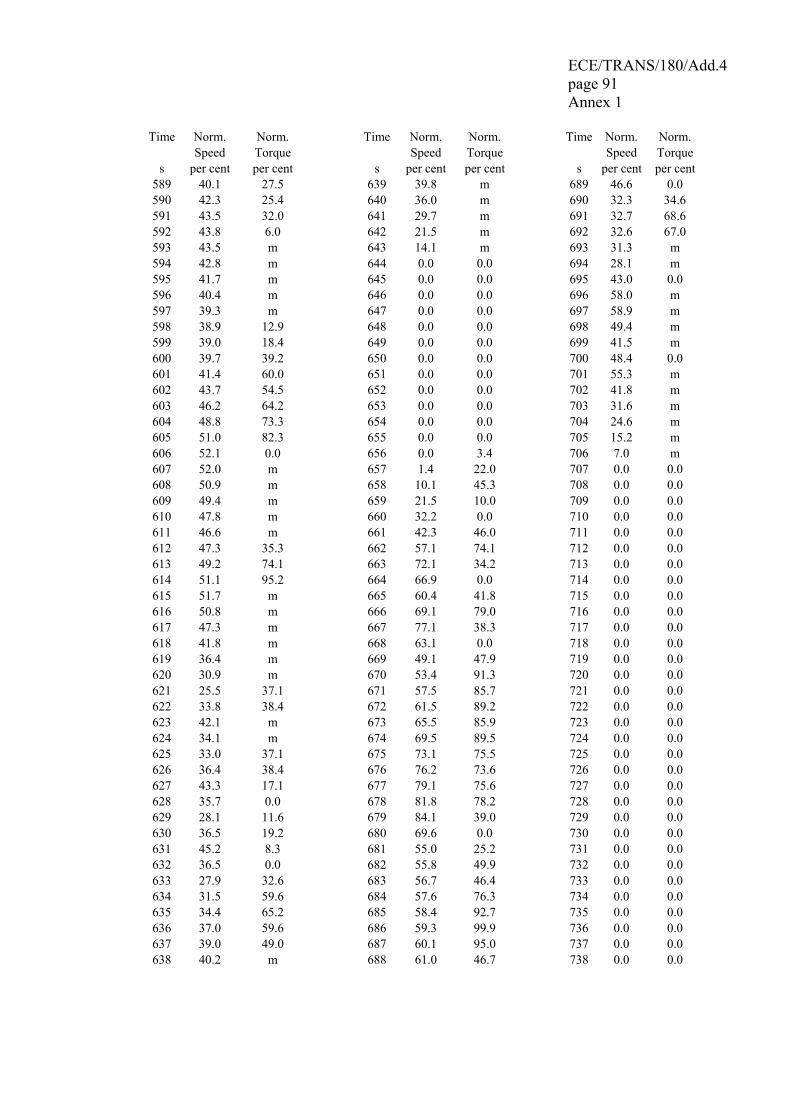
ECE/TRANS/180/Add.4 page 91 Annex 1
Time Norm. Norm. Time Norm. Norm. Time Norm. Norm. Speed Torque Speed Torque Speed Torque s per cent per cent s per cent per cent s per cent per cent
589 40.1 27.5 639 39.8 m 689 46.6 0.0 590 42.3 25.4 640 36.0 m 690 32.3 34.6 591 43.5 32.0 641 29.7 m 691 32.7 68.6 592 43.8 6.0 642 21.5 m 692 32.6 67.0 593 43.5 m 643 14.1 m 693 31.3 m 594 42.8 m 644 0.0 0.0 694 28.1 m 595 41.7 m 645 0.0 0.0 695 43.0 0.0 596 40.4 m 646 0.0 0.0 696 58.0 m 597 39.3 m 647 0.0 0.0 697 58.9 m 598 38.9 12.9 648 0.0 0.0 698 49.4 m 599 39.0 18.4 649 0.0 0.0 699 41.5 m 600 39.7 39.2 650 0.0 0.0 700 48.4 0.0 601 41.4 60.0 651 0.0 0.0 701 55.3 m 602 43.7 54.5 652 0.0 0.0 702 41.8 m 603 46.2 64.2 653 0.0 0.0 703 31.6 m 604 48.8 73.3 654 0.0 0.0 704 24.6 m 605 51.0 82.3 655 0.0 0.0 705 15.2 m 606 52.1 0.0 656 0.0 3.4 706 7.0 m 607 52.0 m 657 1.4 22.0 707 0.0 0.0 608 50.9 m 658 10.1 45.3 708 0.0 0.0 609 49.4 m 659 21.5 10.0 709 0.0 0.0 610 47.8 m 660 32.2 0.0 710 0.0 0.0 611 46.6 m 661 42.3 46.0 711 0.0 0.0 612 47.3 35.3 662 57.1 74.1 712 0.0 0.0 613 49.2 74.1 663 72.1 34.2 713 0.0 0.0 614 51.1 95.2 664 66.9 0.0 714 0.0 0.0 615 51.7 m 665 60.4 41.8 715 0.0 0.0 616 50.8 m 666 69.1 79.0 716 0.0 0.0 617 47.3 m 667 77.1 38.3 717 0.0 0.0 618 41.8 m 668 63.1 0.0 718 0.0 0.0 619 36.4 m 669 49.1 47.9 719 0.0 0.0 620 30.9 m 670 53.4 91.3 720 0.0 0.0 621 25.5 37.1 671 57.5 85.7 721 0.0 0.0 622 33.8 38.4 672 61.5 89.2 722 0.0 0.0 623 42.1 m 673 65.5 85.9 723 0.0 0.0 624 34.1 m 674 69.5 89.5 724 0.0 0.0 625 33.0 37.1 675 73.1 75.5 725 0.0 0.0 626 36.4 38.4 676 76.2 73.6 726 0.0 0.0 627 43.3 17.1 677 79.1 75.6 727 0.0 0.0 628 35.7 0.0 678 81.8 78.2 728 0.0 0.0 629 28.1 11.6 679 84.1 39.0 729 0.0 0.0 630 36.5 19.2 680 69.6 0.0 730 0.0 0.0 631 45.2 8.3 681 55.0 25.2 731 0.0 0.0 632 36.5 0.0 682 55.8 49.9 732 0.0 0.0 633 27.9 32.6 683 56.7 46.4 733 0.0 0.0 634 31.5 59.6 684 57.6 76.3 734 0.0 0.0 635 34.4 65.2 685 58.4 92.7 735 0.0 0.0 636 37.0 59.6 686 59.3 99.9 736 0.0 0.0 637 39.0 49.0 687 60.1 95.0 737 0.0 0.0 638 40.2 m 688 61.0 46.7 738 0.0 0.0
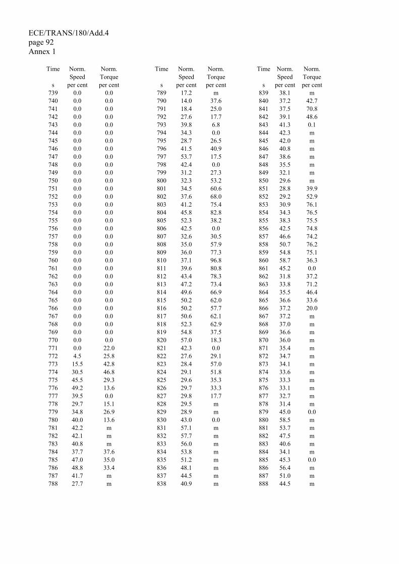
ECE/TRANS/180/Add.4 page 92 Annex 1
Time Norm. Norm. Time Norm. Norm. Time Norm. Norm. Speed Torque Speed Torque Speed Torque s per cent per cent s per cent per cent s per cent per cent
739 0.0 0.0 789 17.2 m 839 38.1 m 740 0.0 0.0 790 14.0 37.6 840 37.2 42.7 741 0.0 0.0 791 18.4 25.0 841 37.5 70.8 742 0.0 0.0 792 27.6 17.7 842 39.1 48.6 743 0.0 0.0 793 39.8 6.8 843 41.3 0.1 744 0.0 0.0 794 34.3 0.0 844 42.3 m 745 0.0 0.0 795 28.7 26.5 845 42.0 m 746 0.0 0.0 796 41.5 40.9 846 40.8 m 747 0.0 0.0 797 53.7 17.5 847 38.6 m 748 0.0 0.0 798 42.4 0.0 848 35.5 m 749 0.0 0.0 799 31.2 27.3 849 32.1 m 750 0.0 0.0 800 32.3 53.2 850 29.6 m 751 0.0 0.0 801 34.5 60.6 851 28.8 39.9 752 0.0 0.0 802 37.6 68.0 852 29.2 52.9 753 0.0 0.0 803 41.2 75.4 853 30.9 76.1 754 0.0 0.0 804 45.8 82.8 854 34.3 76.5 755 0.0 0.0 805 52.3 38.2 855 38.3 75.5 756 0.0 0.0 806 42.5 0.0 856 42.5 74.8 757 0.0 0.0 807 32.6 30.5 857 46.6 74.2 758 0.0 0.0 808 35.0 57.9 858 50.7 76.2 759 0.0 0.0 809 36.0 77.3 859 54.8 75.1 760 0.0 0.0 810 37.1 96.8 860 58.7 36.3 761 0.0 0.0 811 39.6 80.8 861 45.2 0.0 762 0.0 0.0 812 43.4 78.3 862 31.8 37.2 763 0.0 0.0 813 47.2 73.4 863 33.8 71.2 764 0.0 0.0 814 49.6 66.9 864 35.5 46.4 765 0.0 0.0 815 50.2 62.0 865 36.6 33.6 766 0.0 0.0 816 50.2 57.7 866 37.2 20.0 767 0.0 0.0 817 50.6 62.1 867 37.2 m 768 0.0 0.0 818 52.3 62.9 868 37.0 m 769 0.0 0.0 819 54.8 37.5 869 36.6 m 770 0.0 0.0 820 57.0 18.3 870 36.0 m 771 0.0 22.0 821 42.3 0.0 871 35.4 m 772 4.5 25.8 822 27.6 29.1 872 34.7 m 773 15.5 42.8 823 28.4 57.0 873 34.1 m 774 30.5 46.8 824 29.1 51.8 874 33.6 m 775 45.5 29.3 825 29.6 35.3 875 33.3 m 776 49.2 13.6 826 29.7 33.3 876 33.1 m 777 39.5 0.0 827 29.8 17.7 877 32.7 m 778 29.7 15.1 828 29.5 m 878 31.4 m 779 34.8 26.9 829 28.9 m 879 45.0 0.0 780 40.0 13.6 830 43.0 0.0 880 58.5 m 781 42.2 m 831 57.1 m 881 53.7 m 782 42.1 m 832 57.7 m 882 47.5 m 783 40.8 m 833 56.0 m 883 40.6 m 784 37.7 37.6 834 53.8 m 884 34.1 m 785 47.0 35.0 835 51.2 m 885 45.3 0.0 786 48.8 33.4 836 48.1 m 886 56.4 m 787 41.7 m 837 44.5 m 887 51.0 m 788 27.7 m 838 40.9 m 888 44.5 m
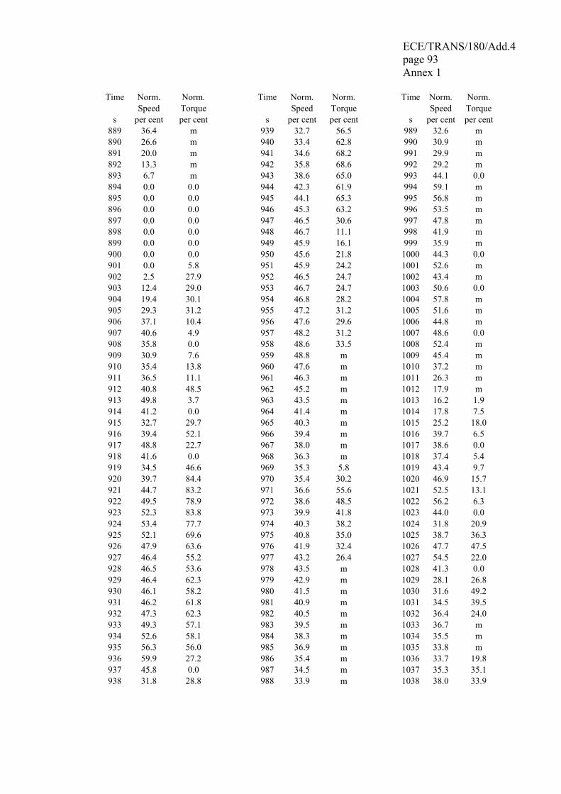
ECE/TRANS/180/Add.4 page 93 Annex 1
Time Norm. Norm. Time Norm. Norm. Time Norm. Norm. Speed Torque Speed Torque Speed Torque s per cent per cent s per cent per cent s per cent per cent
889 36.4 m 939 32.7 56.5 989 32.6 m 890 26.6 m 940 33.4 62.8 990 30.9 m 891 20.0 m 941 34.6 68.2 991 29.9 m 892 13.3 m 942 35.8 68.6 992 29.2 m 893 6.7 m 943 38.6 65.0 993 44.1 0.0 894 0.0 0.0 944 42.3 61.9 994 59.1 m 895 0.0 0.0 945 44.1 65.3 995 56.8 m 896 0.0 0.0 946 45.3 63.2 996 53.5 m 897 0.0 0.0 947 46.5 30.6 997 47.8 m 898 0.0 0.0 948 46.7 11.1 998 41.9 m 899 0.0 0.0 949 45.9 16.1 999 35.9 m 900 0.0 0.0 950 45.6 21.8 1000 44.3 0.0 901 0.0 5.8 951 45.9 24.2 1001 52.6 m 902 2.5 27.9 952 46.5 24.7 1002 43.4 m 903 12.4 29.0 953 46.7 24.7 1003 50.6 0.0 904 19.4 30.1 954 46.8 28.2 1004 57.8 m 905 29.3 31.2 955 47.2 31.2 1005 51.6 m 906 37.1 10.4 956 47.6 29.6 1006 44.8 m 907 40.6 4.9 957 48.2 31.2 1007 48.6 0.0 908 35.8 0.0 958 48.6 33.5 1008 52.4 m 909 30.9 7.6 959 48.8 m 1009 45.4 m 910 35.4 13.8 960 47.6 m 1010 37.2 m 911 36.5 11.1 961 46.3 m 1011 26.3 m 912 40.8 48.5 962 45.2 m 1012 17.9 m 913 49.8 3.7 963 43.5 m 1013 16.2 1.9 914 41.2 0.0 964 41.4 m 1014 17.8 7.5 915 32.7 29.7 965 40.3 m 1015 25.2 18.0 916 39.4 52.1 966 39.4 m 1016 39.7 6.5 917 48.8 22.7 967 38.0 m 1017 38.6 0.0 918 41.6 0.0 968 36.3 m 1018 37.4 5.4 919 34.5 46.6 969 35.3 5.8 1019 43.4 9.7 920 39.7 84.4 970 35.4 30.2 1020 46.9 15.7 921 44.7 83.2 971 36.6 55.6 1021 52.5 13.1 922 49.5 78.9 972 38.6 48.5 1022 56.2 6.3 923 52.3 83.8 973 39.9 41.8 1023 44.0 0.0 924 53.4 77.7 974 40.3 38.2 1024 31.8 20.9 925 52.1 69.6 975 40.8 35.0 1025 38.7 36.3 926 47.9 63.6 976 41.9 32.4 1026 47.7 47.5 927 46.4 55.2 977 43.2 26.4 1027 54.5 22.0 928 46.5 53.6 978 43.5 m 1028 41.3 0.0 929 46.4 62.3 979 42.9 m 1029 28.1 26.8 930 46.1 58.2 980 41.5 m 1030 31.6 49.2 931 46.2 61.8 981 40.9 m 1031 34.5 39.5 932 47.3 62.3 982 40.5 m 1032 36.4 24.0 933 49.3 57.1 983 39.5 m 1033 36.7 m 934 52.6 58.1 984 38.3 m 1034 35.5 m 935 56.3 56.0 985 36.9 m 1035 33.8 m 936 59.9 27.2 986 35.4 m 1036 33.7 19.8 937 45.8 0.0 987 34.5 m 1037 35.3 35.1 938 31.8 28.8 988 33.9 m 1038 38.0 33.9
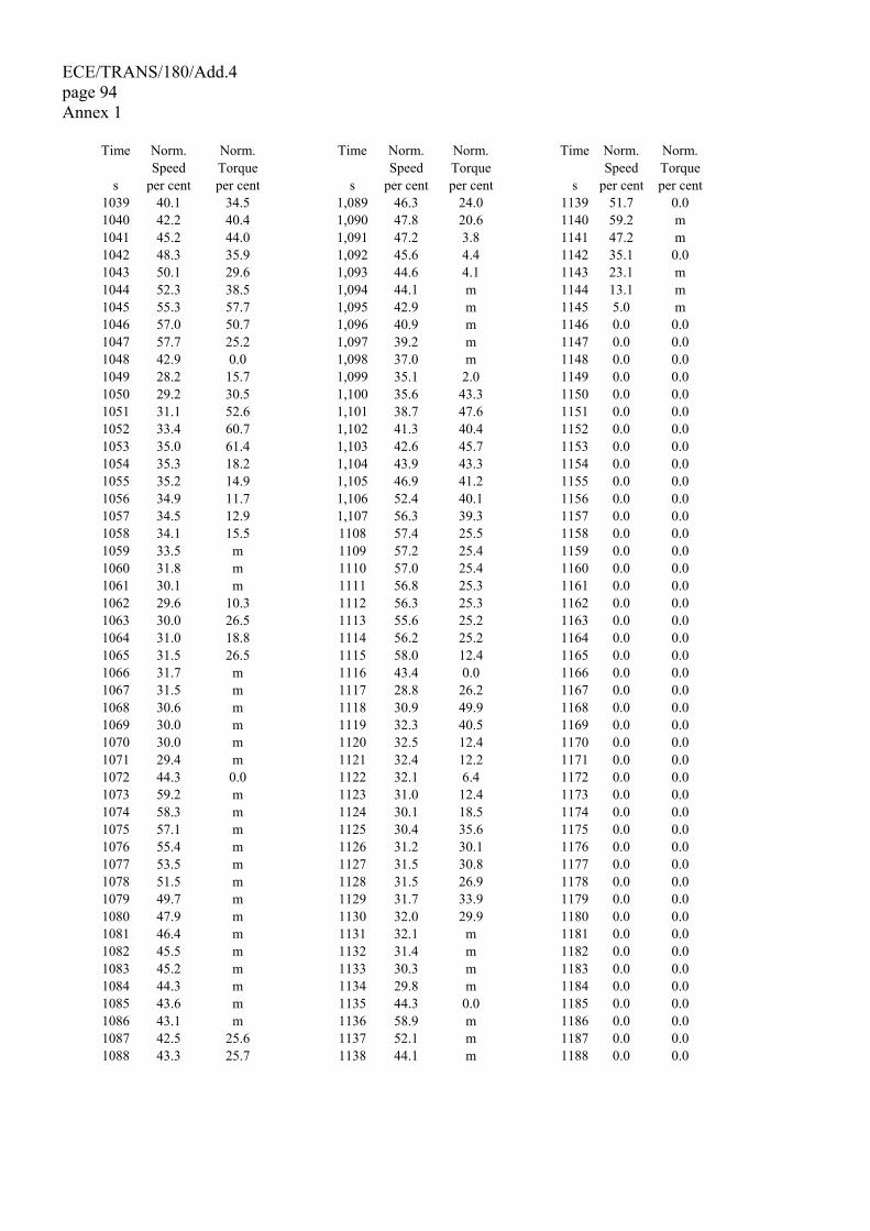
ECE/TRANS/180/Add.4 page 94 Annex 1
Time Norm. Norm. Time Norm. Norm. Time Norm. Norm. Speed Torque Speed Torque Speed Torque s per cent per cent s per cent per cent s per cent per cent
1039 40.1 34.5 1,089 46.3 24.0 1139 51.7 0.0 1040 42.2 40.4 1,090 47.8 20.6 1140 59.2 m 1041 45.2 44.0 1,091 47.2 3.8 1141 47.2 m 1042 48.3 35.9 1,092 45.6 4.4 1142 35.1 0.0 1043 50.1 29.6 1,093 44.6 4.1 1143 23.1 m 1044 52.3 38.5 1,094 44.1 m 1144 13.1 m 1045 55.3 57.7 1,095 42.9 m 1145 5.0 m 1046 57.0 50.7 1,096 40.9 m 1146 0.0 0.0 1047 57.7 25.2 1,097 39.2 m 1147 0.0 0.0 1048 42.9 0.0 1,098 37.0 m 1148 0.0 0.0 1049 28.2 15.7 1,099 35.1 2.0 1149 0.0 0.0 1050 29.2 30.5 1,100 35.6 43.3 1150 0.0 0.0 1051 31.1 52.6 1,101 38.7 47.6 1151 0.0 0.0 1052 33.4 60.7 1,102 41.3 40.4 1152 0.0 0.0 1053 35.0 61.4 1,103 42.6 45.7 1153 0.0 0.0 1054 35.3 18.2 1,104 43.9 43.3 1154 0.0 0.0 1055 35.2 14.9 1,105 46.9 41.2 1155 0.0 0.0 1056 34.9 11.7 1,106 52.4 40.1 1156 0.0 0.0 1057 34.5 12.9 1,107 56.3 39.3 1157 0.0 0.0 1058 34.1 15.5 1108 57.4 25.5 1158 0.0 0.0 1059 33.5 m 1109 57.2 25.4 1159 0.0 0.0 1060 31.8 m 1110 57.0 25.4 1160 0.0 0.0 1061 30.1 m 1111 56.8 25.3 1161 0.0 0.0 1062 29.6 10.3 1112 56.3 25.3 1162 0.0 0.0 1063 30.0 26.5 1113 55.6 25.2 1163 0.0 0.0 1064 31.0 18.8 1114 56.2 25.2 1164 0.0 0.0 1065 31.5 26.5 1115 58.0 12.4 1165 0.0 0.0 1066 31.7 m 1116 43.4 0.0 1166 0.0 0.0 1067 31.5 m 1117 28.8 26.2 1167 0.0 0.0 1068 30.6 m 1118 30.9 49.9 1168 0.0 0.0 1069 30.0 m 1119 32.3 40.5 1169 0.0 0.0 1070 30.0 m 1120 32.5 12.4 1170 0.0 0.0 1071 29.4 m 1121 32.4 12.2 1171 0.0 0.0 1072 44.3 0.0 1122 32.1 6.4 1172 0.0 0.0 1073 59.2 m 1123 31.0 12.4 1173 0.0 0.0 1074 58.3 m 1124 30.1 18.5 1174 0.0 0.0 1075 57.1 m 1125 30.4 35.6 1175 0.0 0.0 1076 55.4 m 1126 31.2 30.1 1176 0.0 0.0 1077 53.5 m 1127 31.5 30.8 1177 0.0 0.0 1078 51.5 m 1128 31.5 26.9 1178 0.0 0.0 1079 49.7 m 1129 31.7 33.9 1179 0.0 0.0 1080 47.9 m 1130 32.0 29.9 1180 0.0 0.0 1081 46.4 m 1131 32.1 m 1181 0.0 0.0 1082 45.5 m 1132 31.4 m 1182 0.0 0.0 1083 45.2 m 1133 30.3 m 1183 0.0 0.0 1084 44.3 m 1134 29.8 m 1184 0.0 0.0 1085 43.6 m 1135 44.3 0.0 1185 0.0 0.0 1086 43.1 m 1136 58.9 m 1186 0.0 0.0 1087 42.5 25.6 1137 52.1 m 1187 0.0 0.0 1088 43.3 25.7 1138 44.1 m 1188 0.0 0.0
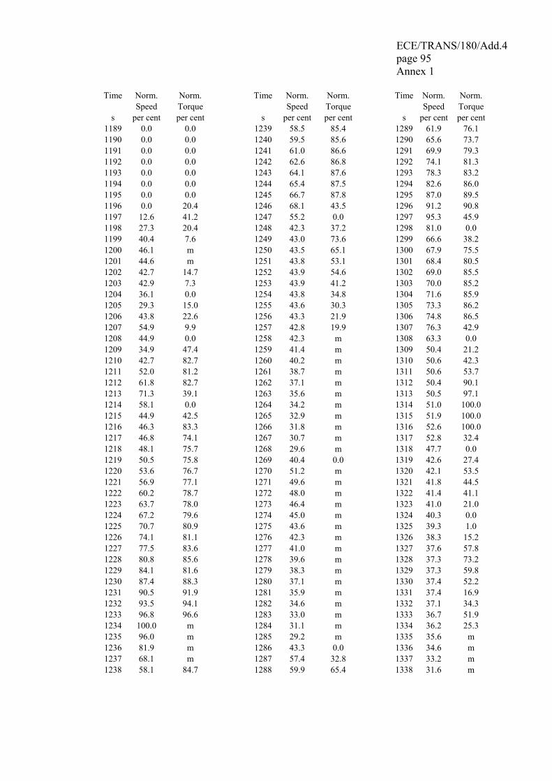
ECE/TRANS/180/Add.4 page 95 Annex 1
Time Norm. Norm. Time Norm. Norm. Time Norm. Norm. Speed Torque Speed Torque Speed Torque s per cent per cent s per cent per cent s per cent per cent
1189 0.0 0.0 1239 58.5 85.4 1289 61.9 76.1 1190 0.0 0.0 1240 59.5 85.6 1290 65.6 73.7 1191 0.0 0.0 1241 61.0 86.6 1291 69.9 79.3 1192 0.0 0.0 1242 62.6 86.8 1292 74.1 81.3 1193 0.0 0.0 1243 64.1 87.6 1293 78.3 83.2 1194 0.0 0.0 1244 65.4 87.5 1294 82.6 86.0 1195 0.0 0.0 1245 66.7 87.8 1295 87.0 89.5 1196 0.0 20.4 1246 68.1 43.5 1296 91.2 90.8 1197 12.6 41.2 1247 55.2 0.0 1297 95.3 45.9 1198 27.3 20.4 1248 42.3 37.2 1298 81.0 0.0 1199 40.4 7.6 1249 43.0 73.6 1299 66.6 38.2 1200 46.1 m 1250 43.5 65.1 1300 67.9 75.5 1201 44.6 m 1251 43.8 53.1 1301 68.4 80.5 1202 42.7 14.7 1252 43.9 54.6 1302 69.0 85.5 1203 42.9 7.3 1253 43.9 41.2 1303 70.0 85.2 1204 36.1 0.0 1254 43.8 34.8 1304 71.6 85.9 1205 29.3 15.0 1255 43.6 30.3 1305 73.3 86.2 1206 43.8 22.6 1256 43.3 21.9 1306 74.8 86.5 1207 54.9 9.9 1257 42.8 19.9 1307 76.3 42.9 1208 44.9 0.0 1258 42.3 m 1308 63.3 0.0 1209 34.9 47.4 1259 41.4 m 1309 50.4 21.2 1210 42.7 82.7 1260 40.2 m 1310 50.6 42.3 1211 52.0 81.2 1261 38.7 m 1311 50.6 53.7 1212 61.8 82.7 1262 37.1 m 1312 50.4 90.1 1213 71.3 39.1 1263 35.6 m 1313 50.5 97.1 1214 58.1 0.0 1264 34.2 m 1314 51.0 100.0 1215 44.9 42.5 1265 32.9 m 1315 51.9 100.0 1216 46.3 83.3 1266 31.8 m 1316 52.6 100.0 1217 46.8 74.1 1267 30.7 m 1317 52.8 32.4 1218 48.1 75.7 1268 29.6 m 1318 47.7 0.0 1219 50.5 75.8 1269 40.4 0.0 1319 42.6 27.4 1220 53.6 76.7 1270 51.2 m 1320 42.1 53.5 1221 56.9 77.1 1271 49.6 m 1321 41.8 44.5 1222 60.2 78.7 1272 48.0 m 1322 41.4 41.1 1223 63.7 78.0 1273 46.4 m 1323 41.0 21.0 1224 67.2 79.6 1274 45.0 m 1324 40.3 0.0 1225 70.7 80.9 1275 43.6 m 1325 39.3 1.0 1226 74.1 81.1 1276 42.3 m 1326 38.3 15.2 1227 77.5 83.6 1277 41.0 m 1327 37.6 57.8 1228 80.8 85.6 1278 39.6 m 1328 37.3 73.2 1229 84.1 81.6 1279 38.3 m 1329 37.3 59.8 1230 87.4 88.3 1280 37.1 m 1330 37.4 52.2 1231 90.5 91.9 1281 35.9 m 1331 37.4 16.9 1232 93.5 94.1 1282 34.6 m 1332 37.1 34.3 1233 96.8 96.6 1283 33.0 m 1333 36.7 51.9 1234 100.0 m 1284 31.1 m 1334 36.2 25.3 1235 96.0 m 1285 29.2 m 1335 35.6 m 1236 81.9 m 1286 43.3 0.0 1336 34.6 m 1237 68.1 m 1287 57.4 32.8 1337 33.2 m 1238 58.1 84.7 1288 59.9 65.4 1338 31.6 m
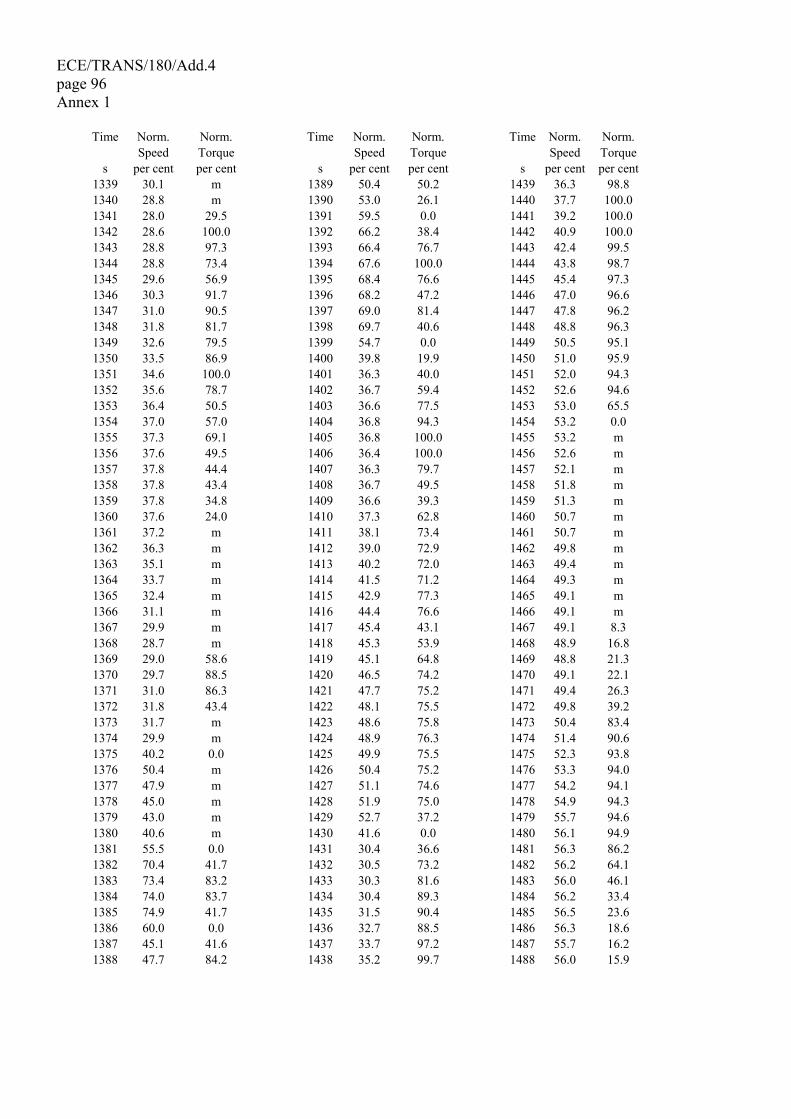
ECE/TRANS/180/Add.4 page 96 Annex 1
Time Norm. Norm. Time Norm. Norm. Time Norm. Norm. Speed Torque Speed Torque Speed Torque s per cent per cent s per cent per cent s per cent per cent
1339 30.1 m 1389 50.4 50.2 1439 36.3 98.8 1340 28.8 m 1390 53.0 26.1 1440 37.7 100.0 1341 28.0 29.5 1391 59.5 0.0 1441 39.2 100.0 1342 28.6 100.0 1392 66.2 38.4 1442 40.9 100.0 1343 28.8 97.3 1393 66.4 76.7 1443 42.4 99.5 1344 28.8 73.4 1394 67.6 100.0 1444 43.8 98.7 1345 29.6 56.9 1395 68.4 76.6 1445 45.4 97.3 1346 30.3 91.7 1396 68.2 47.2 1446 47.0 96.6 1347 31.0 90.5 1397 69.0 81.4 1447 47.8 96.2 1348 31.8 81.7 1398 69.7 40.6 1448 48.8 96.3 1349 32.6 79.5 1399 54.7 0.0 1449 50.5 95.1 1350 33.5 86.9 1400 39.8 19.9 1450 51.0 95.9 1351 34.6 100.0 1401 36.3 40.0 1451 52.0 94.3 1352 35.6 78.7 1402 36.7 59.4 1452 52.6 94.6 1353 36.4 50.5 1403 36.6 77.5 1453 53.0 65.5 1354 37.0 57.0 1404 36.8 94.3 1454 53.2 0.0 1355 37.3 69.1 1405 36.8 100.0 1455 53.2 m 1356 37.6 49.5 1406 36.4 100.0 1456 52.6 m 1357 37.8 44.4 1407 36.3 79.7 1457 52.1 m 1358 37.8 43.4 1408 36.7 49.5 1458 51.8 m 1359 37.8 34.8 1409 36.6 39.3 1459 51.3 m 1360 37.6 24.0 1410 37.3 62.8 1460 50.7 m 1361 37.2 m 1411 38.1 73.4 1461 50.7 m 1362 36.3 m 1412 39.0 72.9 1462 49.8 m 1363 35.1 m 1413 40.2 72.0 1463 49.4 m 1364 33.7 m 1414 41.5 71.2 1464 49.3 m 1365 32.4 m 1415 42.9 77.3 1465 49.1 m 1366 31.1 m 1416 44.4 76.6 1466 49.1 m 1367 29.9 m 1417 45.4 43.1 1467 49.1 8.3 1368 28.7 m 1418 45.3 53.9 1468 48.9 16.8 1369 29.0 58.6 1419 45.1 64.8 1469 48.8 21.3 1370 29.7 88.5 1420 46.5 74.2 1470 49.1 22.1 1371 31.0 86.3 1421 47.7 75.2 1471 49.4 26.3 1372 31.8 43.4 1422 48.1 75.5 1472 49.8 39.2 1373 31.7 m 1423 48.6 75.8 1473 50.4 83.4 1374 29.9 m 1424 48.9 76.3 1474 51.4 90.6 1375 40.2 0.0 1425 49.9 75.5 1475 52.3 93.8 1376 50.4 m 1426 50.4 75.2 1476 53.3 94.0 1377 47.9 m 1427 51.1 74.6 1477 54.2 94.1 1378 45.0 m 1428 51.9 75.0 1478 54.9 94.3 1379 43.0 m 1429 52.7 37.2 1479 55.7 94.6 1380 40.6 m 1430 41.6 0.0 1480 56.1 94.9 1381 55.5 0.0 1431 30.4 36.6 1481 56.3 86.2 1382 70.4 41.7 1432 30.5 73.2 1482 56.2 64.1 1383 73.4 83.2 1433 30.3 81.6 1483 56.0 46.1 1384 74.0 83.7 1434 30.4 89.3 1484 56.2 33.4 1385 74.9 41.7 1435 31.5 90.4 1485 56.5 23.6 1386 60.0 0.0 1436 32.7 88.5 1486 56.3 18.6 1387 45.1 41.6 1437 33.7 97.2 1487 55.7 16.2 1388 47.7 84.2 1438 35.2 99.7 1488 56.0 15.9
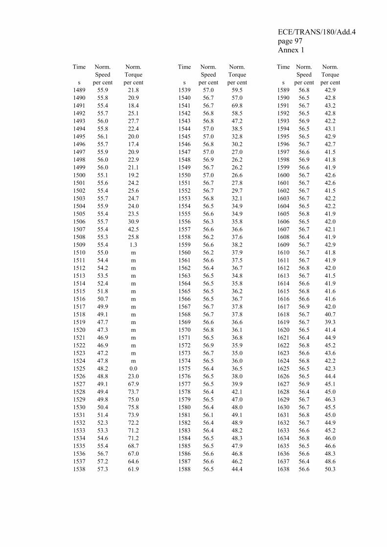
ECE/TRANS/180/Add.4 page 97 Annex 1
Time Norm. Norm. Time Norm. Norm. Time Norm. Norm. Speed Torque Speed Torque Speed Torque s per cent per cent s per cent per cent s per cent per cent
1489 55.9 21.8 1539 57.0 59.5 1589 56.8 42.9 1490 55.8 20.9 1540 56.7 57.0 1590 56.5 42.8 1491 55.4 18.4 1541 56.7 69.8 1591 56.7 43.2 1492 55.7 25.1 1542 56.8 58.5 1592 56.5 42.8 1493 56.0 27.7 1543 56.8 47.2 1593 56.9 42.2 1494 55.8 22.4 1544 57.0 38.5 1594 56.5 43.1 1495 56.1 20.0 1545 57.0 32.8 1595 56.5 42.9 1496 55.7 17.4 1546 56.8 30.2 1596 56.7 42.7 1497 55.9 20.9 1547 57.0 27.0 1597 56.6 41.5 1498 56.0 22.9 1548 56.9 26.2 1598 56.9 41.8 1499 56.0 21.1 1549 56.7 26.2 1599 56.6 41.9 1500 55.1 19.2 1550 57.0 26.6 1600 56.7 42.6 1501 55.6 24.2 1551 56.7 27.8 1601 56.7 42.6 1502 55.4 25.6 1552 56.7 29.7 1602 56.7 41.5 1503 55.7 24.7 1553 56.8 32.1 1603 56.7 42.2 1504 55.9 24.0 1554 56.5 34.9 1604 56.5 42.2 1505 55.4 23.5 1555 56.6 34.9 1605 56.8 41.9 1506 55.7 30.9 1556 56.3 35.8 1606 56.5 42.0 1507 55.4 42.5 1557 56.6 36.6 1607 56.7 42.1 1508 55.3 25.8 1558 56.2 37.6 1608 56.4 41.9 1509 55.4 1.3 1559 56.6 38.2 1609 56.7 42.9 1510 55.0 m 1560 56.2 37.9 1610 56.7 41.8 1511 54.4 m 1561 56.6 37.5 1611 56.7 41.9 1512 54.2 m 1562 56.4 36.7 1612 56.8 42.0 1513 53.5 m 1563 56.5 34.8 1613 56.7 41.5 1514 52.4 m 1564 56.5 35.8 1614 56.6 41.9 1515 51.8 m 1565 56.5 36.2 1615 56.8 41.6 1516 50.7 m 1566 56.5 36.7 1616 56.6 41.6 1517 49.9 m 1567 56.7 37.8 1617 56.9 42.0 1518 49.1 m 1568 56.7 37.8 1618 56.7 40.7 1519 47.7 m 1569 56.6 36.6 1619 56.7 39.3 1520 47.3 m 1570 56.8 36.1 1620 56.5 41.4 1521 46.9 m 1571 56.5 36.8 1621 56.4 44.9 1522 46.9 m 1572 56.9 35.9 1622 56.8 45.2 1523 47.2 m 1573 56.7 35.0 1623 56.6 43.6 1524 47.8 m 1574 56.5 36.0 1624 56.8 42.2 1525 48.2 0.0 1575 56.4 36.5 1625 56.5 42.3 1526 48.8 23.0 1576 56.5 38.0 1626 56.5 44.4 1527 49.1 67.9 1577 56.5 39.9 1627 56.9 45.1 1528 49.4 73.7 1578 56.4 42.1 1628 56.4 45.0 1529 49.8 75.0 1579 56.5 47.0 1629 56.7 46.3 1530 50.4 75.8 1580 56.4 48.0 1630 56.7 45.5 1531 51.4 73.9 1581 56.1 49.1 1631 56.8 45.0 1532 52.3 72.2 1582 56.4 48.9 1632 56.7 44.9 1533 53.3 71.2 1583 56.4 48.2 1633 56.6 45.2 1534 54.6 71.2 1584 56.5 48.3 1634 56.8 46.0 1535 55.4 68.7 1585 56.5 47.9 1635 56.5 46.6 1536 56.7 67.0 1586 56.6 46.8 1636 56.6 48.3 1537 57.2 64.6 1587 56.6 46.2 1637 56.4 48.6 1538 57.3 61.9 1588 56.5 44.4 1638 56.6 50.3

ECE/TRANS/180/Add.4 page 98 Annex 1
Time Norm. Norm. Time Norm. Norm. Time Norm. Norm. Speed Torque Speed Torque Speed Torque s per cent per cent s per cent per cent s per cent per cent
1639 56.3 51.9 1689 57.6 8.9 1739 56.1 46.8 1640 56.5 54.1 1690 57.5 8.0 1740 56.1 45.8 1641 56.3 54.9 1691 57.5 5.8 1741 56.2 46.0 1642 56.4 55.0 1692 57.3 5.8 1742 56.3 45.9 1643 56.4 56.2 1693 57.6 5.5 1743 56.3 45.9 1644 56.2 58.6 1694 57.3 4.5 1744 56.2 44.6 1645 56.2 59.1 1695 57.2 3.2 1745 56.2 46.0 1646 56.2 62.5 1696 57.2 3.1 1746 56.4 46.2 1647 56.4 62.8 1697 57.3 4.9 1747 55.8 m 1648 56.0 64.7 1698 57.3 4.2 1748 55.5 m 1649 56.4 65.6 1699 56.9 5.5 1749 55.0 m 1650 56.2 67.7 1700 57.1 5.1 1750 54.1 m 1651 55.9 68.9 1701 57.0 5.2 1751 54.0 m 1652 56.1 68.9 1702 56.9 5.5 1752 53.3 m 1653 55.8 69.5 1703 56.6 5.4 1753 52.6 m 1654 56.0 69.8 1704 57.1 6.1 1754 51.8 m 1655 56.2 69.3 1705 56.7 5.7 1755 50.7 m 1656 56.2 69.8 1706 56.8 5.8 1756 49.9 m 1657 56.4 69.2 1707 57.0 6.1 1757 49.1 m 1658 56.3 68.7 1708 56.7 5.9 1758 47.7 m 1659 56.2 69.4 1709 57.0 6.6 1759 46.8 m 1660 56.2 69.5 1710 56.9 6.4 1760 45.7 m 1661 56.2 70.0 1711 56.7 6.7 1761 44.8 m 1662 56.4 69.7 1712 56.9 6.9 1762 43.9 m 1663 56.2 70.2 1713 56.8 5.6 1763 42.9 m 1664 56.4 70.5 1714 56.6 5.1 1764 41.5 m 1665 56.1 70.5 1715 56.6 6.5 1765 39.5 m 1666 56.5 69.7 1716 56.5 10.0 1766 36.7 m 1667 56.2 69.3 1717 56.6 12.4 1767 33.8 m 1668 56.5 70.9 1718 56.5 14.5 1768 31.0 m 1669 56.4 70.8 1719 56.6 16.3 1769 40.0 0.0 1670 56.3 71.1 1720 56.3 18.1 1770 49.1 m 1671 56.4 71.0 1721 56.6 20.7 1771 46.2 m 1672 56.7 68.6 1722 56.1 22.6 1772 43.1 m 1673 56.8 68.6 1723 56.3 25.8 1773 39.9 m 1674 56.6 68.0 1724 56.4 27.7 1774 36.6 m 1675 56.8 65.1 1725 56.0 29.7 1775 33.6 m 1676 56.9 60.9 1726 56.1 32.6 1776 30.5 m 1677 57.1 57.4 1727 55.9 34.9 1777 42.8 0.0 1678 57.1 54.3 1728 55.9 36.4 1778 55.2 m 1679 57.0 48.6 1729 56.0 39.2 1779 49.9 m 1680 57.4 44.1 1730 55.9 41.4 1780 44.0 m 1681 57.4 40.2 1731 55.5 44.2 1781 37.6 m 1682 57.6 36.9 1732 55.9 46.4 1782 47.2 0.0 1683 57.5 34.2 1733 55.8 48.3 1783 56.8 m 1684 57.4 31.1 1734 55.6 49.1 1784 47.5 m 1685 57.5 25.9 1735 55.8 49.3 1785 42.9 m 1686 57.5 20.7 1736 55.9 47.7 1786 31.6 m 1687 57.6 16.4 1737 55.9 47.4 1787 25.8 m 1688 57.6 12.4 1738 55.8 46.9 1788 19.9 m

ECE/TRANS/180/Add.4 page 99 Annex 1
Time Norm. Norm. Time Norm. Norm. Time Norm. Norm. Speed Torque Speed Torque Speed Torque s per cent per cent s per cent per cent s per cent per cent
1789 14.0 m 1790 8.1 m 1791 2.2 m 1792 0.0 0.0 1793 0.0 0.0 1794 0.0 0.0 1795 0.0 0.0 1796 0.0 0.0 1797 0.0 0.0 1798 0.0 0.0 1799 0.0 0.0 1800 0.0 0.0
m = motoring
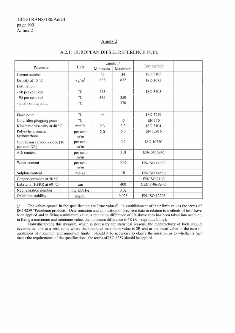
ECE/TRANS/180/Add.4 page 100 Annex 2
Annex 2
A.2.1. EUROPEAN DIESEL REFERENCE FUEL
Limits 1/ Parameter Unit Minimum Maximum
Test method
Cetene number 52 54 ISO 5165 Density at 15 °C kg/m3 833 837 ISO 3675 Distillation: - 50 per cent vol. °C 245 ISO 3405 - 95 per cent vol °C 345 350 - final boiling point °C 370 Flash point °C 55 ISO 2719 Cold filter plugging point °C -5 EN 116 Kinematic viscosity at 40 °C mm2/s 2.3 3.3 ISO 3104 Polycylic aromatic hydrocarbons
per cent m/m
2.0 6.0 EN 12916
Conradson carbon residue (10 per cent DR)
per cent m/m
0.2 ISO 10370
Ash content per cent m/m
0.01 EN-ISO 6245
Water content per cent m/m
0.02 EN-ISO 12937
Sulphur content mg/kg 10 EN-ISO 14596 Copper corrosion at 50 °C 1 EN-ISO 2160 Lubricity (HFRR at 60 °C) µm 400 CEC F-06-A-96 Neutralisation number mg KOH/g 0.02 Oxidation stability mg/ml 0.025 EN-ISO 12205 1/ The values quoted in the specification are "true values". In establishment of their limit values the terms of ISO 4259 "Petroleum products - Determination and application of precision data in relation to methods of test.' have been applied and in fixing a minimum value, a minimum difference of 2R above zero has been taken into account; in fixing a maximum and minimum value, the minimum difference is 4R (R = reproducibility). Notwithstanding this measure, which is necessary for statistical reasons, the manufacturer of fuels should nevertheless aim at a zero value where the stipulated maximum value is 2R and at the mean value in the case of quotations of maximum and minimum limits. Should it be necessary to clarify the question as to whether a fuel meets the requirements of the specifications, the terms of ISO 4259 should be applied.
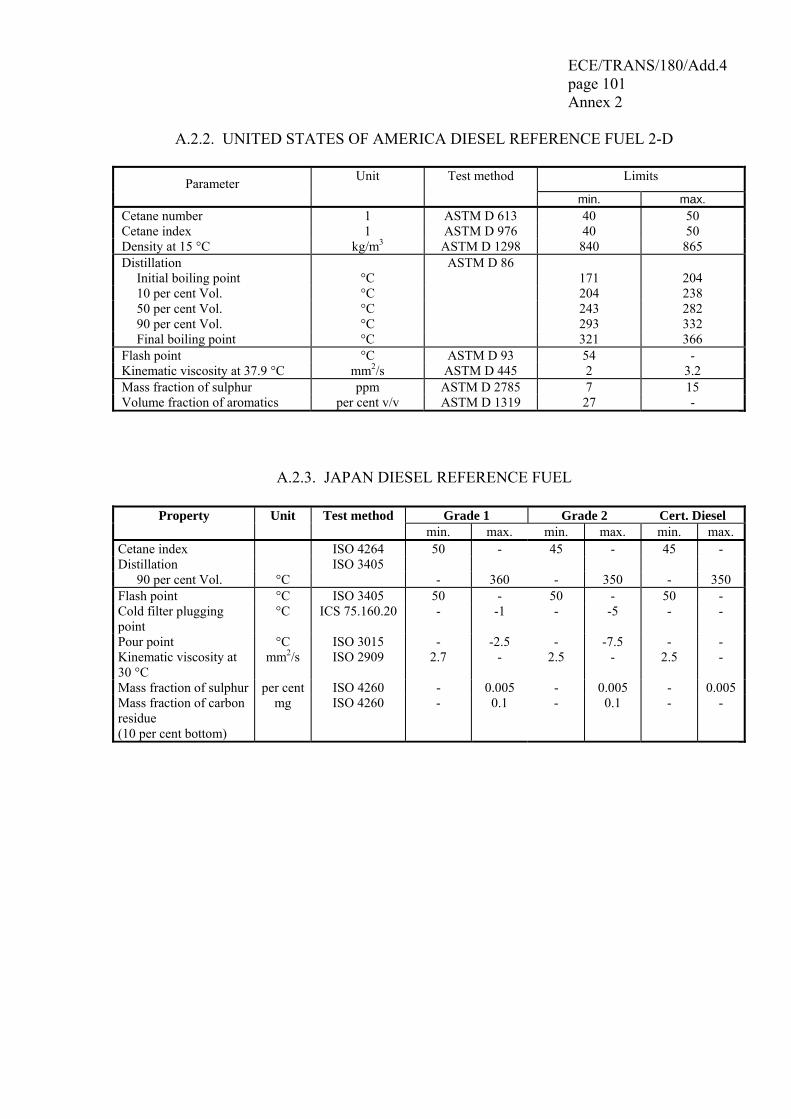
ECE/TRANS/180/Add.4 page 101 Annex 2
A.2.2. UNITED STATES OF AMERICA DIESEL REFERENCE FUEL 2-D
Parameter Unit Test method Limits
min. max. Cetane number 1 ASTM D 613 40 50 Cetane index 1 ASTM D 976 40 50 Density at 15 °C kg/m3 ASTM D 1298 840 865 Distillation ASTM D 86
Initial boiling point °C 171 204 10 per cent Vol. °C 204 238 50 per cent Vol. °C 243 282 90 per cent Vol. °C 293 332 Final boiling point °C 321 366
Flash point °C ASTM D 93 54 - Kinematic viscosity at 37.9 °C mm2/s ASTM D 445 2 3.2 Mass fraction of sulphur ppm ASTM D 2785 7 15 Volume fraction of aromatics per cent v/v ASTM D 1319 27 -
A.2.3. JAPAN DIESEL REFERENCE FUEL
Property Unit Test method Grade 1 Grade 2 Cert. Diesel min. max. min. max. min. max.
Cetane index ISO 4264 50 - 45 - 45 - Distillation ISO 3405
90 per cent Vol. °C - 360 - 350 - 350 Flash point °C ISO 3405 50 - 50 - 50 - Cold filter plugging point
°C ICS 75.160.20 - -1 - -5 - -
Pour point °C ISO 3015 - -2.5 - -7.5 - - Kinematic viscosity at 30 °C
mm2/s ISO 2909 2.7 - 2.5 - 2.5 -
Mass fraction of sulphur per cent ISO 4260 - 0.005 - 0.005 - 0.005 Mass fraction of carbon residue (10 per cent bottom)
mg ISO 4260 - 0.1 - 0.1 - -
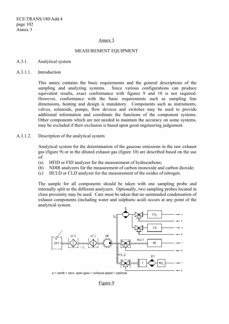
ECE/TRANS/180/Add.4 page 102 Annex 3
Annex 3
MEASUREMENT EQUIPMENT A.3.1. Analytical system A.3.1.1. Introduction This annex contains the basic requirements and the general descriptions of the
sampling and analyzing systems. Since various configurations can produce equivalent results, exact conformance with figures 9 and 10 is not required. However, conformance with the basic requirements such as sampling line dimensions, heating and design is mandatory. Components such as instruments, valves, solenoids, pumps, flow devices and switches may be used to provide additional information and coordinate the functions of the component systems. Other components which are not needed to maintain the accuracy on some systems, may be excluded if their exclusion is based upon good engineering judgement.
A.3.1.2. Description of the analytical system Analytical system for the determination of the gaseous emissions in the raw exhaust
gas (figure 9) or in the diluted exhaust gas (figure 10) are described based on the use of:
(a) HFID or FID analyzer for the measurement of hydrocarbons; (b) NDIR analyzers for the measurement of carbon monoxide and carbon dioxide; (c) HCLD or CLD analyzer for the measurement of the oxides of nitrogen. The sample for all components should be taken with one sampling probe and
internally split to the different analyzers. Optionally, two sampling probes located in close proximity may be used. Care must be taken that no unintended condensation of exhaust components (including water and sulphuric acid) occurs at any point of the analytical system.
a = ventb = zero, span gasc = exhaust piped = optional
Figure 9

ECE/TRANS/180/Add.4 page 103 Annex 3
Schematic flow diagram of raw exhaust gas analysis system for CO, CO2, NOx, HC
a = ventb = zero, span gasc = dilution tunneld = optional
Figure 10 Schematic flow diagram of diluted exhaust gas analysis system for CO, CO2, NOx, HC
A.3.1.3. Components of figures 9 and 10 EP Exhaust pipe SP Raw exhaust gas sampling probe (figure 9 only) A stainless steel straight closed end multi-hole probe is recommended. The inside
diameter shall not be greater than the inside diameter of the sampling line. The wall thickness of the probe shall not be greater than 1 mm. There shall be a minimum of 3 holes in 3 different radial planes sized to sample approximately the same flow. The probe shall extend across at least 80 per cent of the diameter of the exhaust pipe. One or two sampling probes may be used.
SP2 Dilute exhaust gas HC sampling probe (figure 10 only) The probe shall: (a) be defined as the first 254 mm to 762 mm of the heated sampling line HSL1 (b) have a 5 mm minimum inside diameter (c) be installed in the dilution tunnel DT (figure 15) at a point where the dilution
air and exhaust gas are well mixed (i.e. approximately 10 tunnel diameters downstream of the point where the exhaust enters the dilution tunnel)
(d) be sufficiently distant (radially) from other probes and the tunnel wall so as to be free from the influence of any wakes or eddies
ECE/TRANS/180/Add.4 page 104 Annex 3 (e) be heated so as to increase the gas stream temperature to 463 K ± 10 K
(190 °C ± 10 °C) at the exit of the probe, or to 385 K ± 10 K (112 °C ± 10 °C) for positive ignition engines
(f) non-heated in case of FID measurement (cold) SP3 Dilute exhaust gas CO, CO2, NOx sampling probe (figure 10 only) The probe shall: (a) be in the same plane as SP2 (b) be sufficiently distant (radially) from other probes and the tunnel wall so as to
be free from the influence of any wakes or eddies (c) be heated and insulated over its entire length to a minimum temperature
of 328 K (55 °C) to prevent water condensation HF1 Heated pre-filter (optional) The temperature shall be the same as HSL1. HF2 Heated filter The filter shall extract any solid particles from the gas sample prior to the analyzer.
The temperature shall be the same as HSL1. The filter shall be changed as needed. HSL1 Heated sampling line The sampling line provides a gas sample from a single probe to the split point(s) and
the HC analyzer. The sampling line shall: (a) have a 4 mm minimum and a 13.5 mm maximum inside diameter (b) be made of stainless steel or PTFE (c) maintain a wall temperature of 463 K ± 10 K (190 °C ± 10 °C) as measured at
every separately controlled heated section, if the temperature of the exhaust gas at the sampling probe is equal to or below 463 K (190 °C)
(d) maintain a wall temperature greater than 453 K (180 °C), if the temperature of the exhaust gas at the sampling probe is above 463 K (190 °C)
(e) maintain a gas temperature of 463 K ± 10 K (190 °C ± 10 °C) immediately before the heated filter HF2 and the HFID
HSL2 Heated NOx sampling line The sampling line shall: (a) maintain a wall temperature of 328 K to 473 K (55 °C to 200 °C), up to the
converter for dry measurement, and up to the analyzer for wet measurement (b) be made of stainless steel or PTFE
ECE/TRANS/180/Add.4 page 105 Annex 3
HP Heated sampling pump The pump shall be heated to the temperature of HSL. SL Sampling line for CO and CO2 The line shall be made of PTFE or stainless steel. It may be heated or unheated. HC HFID analyzer Heated flame ionization detector (HFID) or flame ionization detector (FID) for the
determination of the hydrocarbons. The temperature of the HFID shall be kept at 453 K to 473 K (180 °C to 200 °C).
CO, CO2 NDIR analyzer NDIR analyzers for the determination of carbon monoxide and carbon dioxide
(optional for the determination of the dilution ratio for PT measurement). NOx CLD analyzer CLD or HCLD analyzer for the determination of the oxides of nitrogen. If a HCLD
is used it shall be kept at a temperature of 328 K to 473 K (55 °C to 200 °C). B Cooling bath (optional for NO measurement) To cool and condense water from the exhaust sample. It is optional if the analyzer is
free from water vapour interference as determined in paragraph 9.3.9.2.2. If water is removed by condensation, the sample gas temperature or dew point shall be monitored either within the water trap or downstream. The sample gas temperature or dew point shall not exceed 280 K (7 °C). Chemical dryers are not allowed for removing water from the sample.
BK Background bag (optional; figure 10 only) For the measurement of the background concentrations. BG Sample bag (optional; figure 10 only) For the measurement of the sample concentrations. A.3.1.4. Non-methane cutter method (NMC) The cutter oxidizes all hydrocarbons except CH4 to CO2 and H2O, so that by passing
the sample through the NMC only CH4 is detected by the HFID. In addition to the usual HC sampling train (see figures 9 and 10), a second HC sampling train shall be
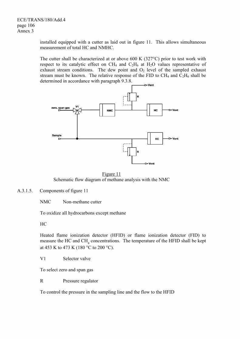
ECE/TRANS/180/Add.4 page 106 Annex 3
installed equipped with a cutter as laid out in figure 11. This allows simultaneous measurement of total HC and NMHC.
The cutter shall be characterized at or above 600 K (327°C) prior to test work with
respect to its catalytic effect on CH4 and C2H6 at H2O values representative of exhaust stream conditions. The dew point and O2 level of the sampled exhaust stream must be known. The relative response of the FID to CH4 and C2H6 shall be determined in accordance with paragraph 9.3.8.
Figure 11 Schematic flow diagram of methane analysis with the NMC
A.3.1.5. Components of figure 11 NMC Non-methane cutter To oxidize all hydrocarbons except methane HC Heated flame ionization detector (HFID) or flame ionization detector (FID) to
measure the HC and CH4 concentrations. The temperature of the HFID shall be kept at 453 K to 473 K (180 °C to 200 °C).
V1 Selector valve To select zero and span gas R Pressure regulator To control the pressure in the sampling line and the flow to the HFID
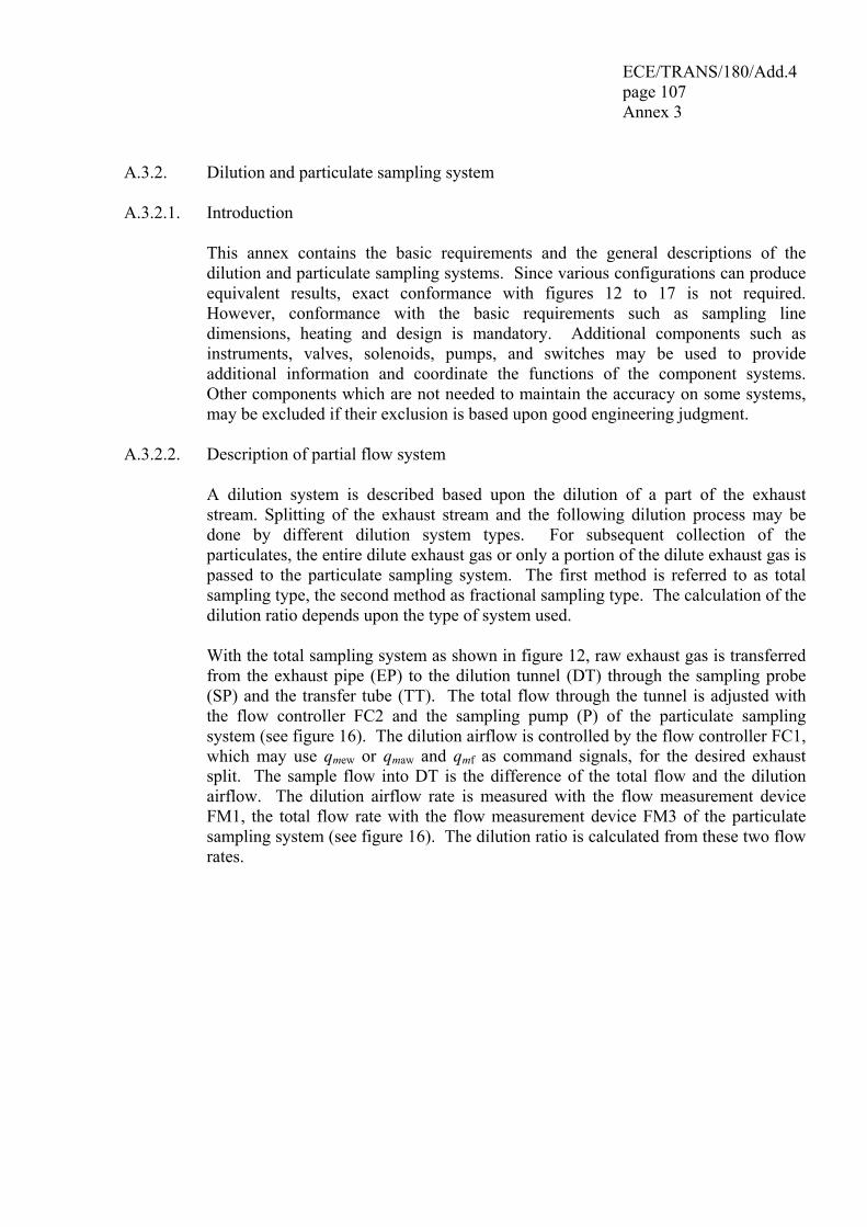
ECE/TRANS/180/Add.4 page 107 Annex 3
A.3.2. Dilution and particulate sampling system A.3.2.1. Introduction This annex contains the basic requirements and the general descriptions of the
dilution and particulate sampling systems. Since various configurations can produce equivalent results, exact conformance with figures 12 to 17 is not required. However, conformance with the basic requirements such as sampling line dimensions, heating and design is mandatory. Additional components such as instruments, valves, solenoids, pumps, and switches may be used to provide additional information and coordinate the functions of the component systems. Other components which are not needed to maintain the accuracy on some systems, may be excluded if their exclusion is based upon good engineering judgment.
A.3.2.2. Description of partial flow system A dilution system is described based upon the dilution of a part of the exhaust
stream. Splitting of the exhaust stream and the following dilution process may be done by different dilution system types. For subsequent collection of the particulates, the entire dilute exhaust gas or only a portion of the dilute exhaust gas is passed to the particulate sampling system. The first method is referred to as total sampling type, the second method as fractional sampling type. The calculation of the dilution ratio depends upon the type of system used.
With the total sampling system as shown in figure 12, raw exhaust gas is transferred
from the exhaust pipe (EP) to the dilution tunnel (DT) through the sampling probe (SP) and the transfer tube (TT). The total flow through the tunnel is adjusted with the flow controller FC2 and the sampling pump (P) of the particulate sampling system (see figure 16). The dilution airflow is controlled by the flow controller FC1, which may use qmew or qmaw and qmf as command signals, for the desired exhaust split. The sample flow into DT is the difference of the total flow and the dilution airflow. The dilution airflow rate is measured with the flow measurement device FM1, the total flow rate with the flow measurement device FM3 of the particulate sampling system (see figure 16). The dilution ratio is calculated from these two flow rates.
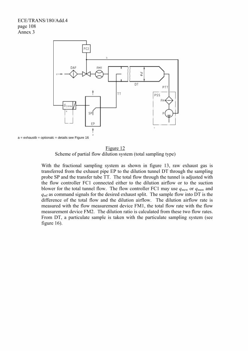
ECE/TRANS/180/Add.4 page 108 Annex 3
a = exhaustb = optionalc = details see Figure 16
Figure 12 Scheme of partial flow dilution system (total sampling type)
With the fractional sampling system as shown in figure 13, raw exhaust gas is
transferred from the exhaust pipe EP to the dilution tunnel DT through the sampling probe SP and the transfer tube TT. The total flow through the tunnel is adjusted with the flow controller FC1 connected either to the dilution airflow or to the suction blower for the total tunnel flow. The flow controller FC1 may use qmew or qmaw and qmf as command signals for the desired exhaust split. The sample flow into DT is the difference of the total flow and the dilution airflow. The dilution airflow rate is measured with the flow measurement device FM1, the total flow rate with the flow measurement device FM2. The dilution ratio is calculated from these two flow rates. From DT, a particulate sample is taken with the particulate sampling system (see figure 16).
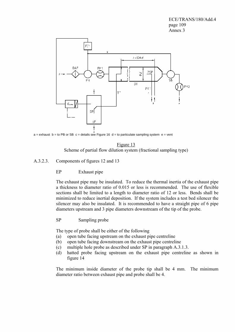
ECE/TRANS/180/Add.4 page 109 Annex 3
a = exhaust b = to PB or SB c = details see Figure 16 d = to particulate sampling system e = vent
Figure 13 Scheme of partial flow dilution system (fractional sampling type)
A.3.2.3. Components of figures 12 and 13 EP Exhaust pipe The exhaust pipe may be insulated. To reduce the thermal inertia of the exhaust pipe
a thickness to diameter ratio of 0.015 or less is recommended. The use of flexible sections shall be limited to a length to diameter ratio of 12 or less. Bends shall be minimized to reduce inertial deposition. If the system includes a test bed silencer the silencer may also be insulated. It is recommended to have a straight pipe of 6 pipe diameters upstream and 3 pipe diameters downstream of the tip of the probe.
SP Sampling probe The type of probe shall be either of the following (a) open tube facing upstream on the exhaust pipe centreline (b) open tube facing downstream on the exhaust pipe centreline (c) multiple hole probe as described under SP in paragraph A.3.1.3. (d) hatted probe facing upstream on the exhaust pipe centreline as shown in
figure 14 The minimum inside diameter of the probe tip shall be 4 mm. The minimum
diameter ratio between exhaust pipe and probe shall be 4.
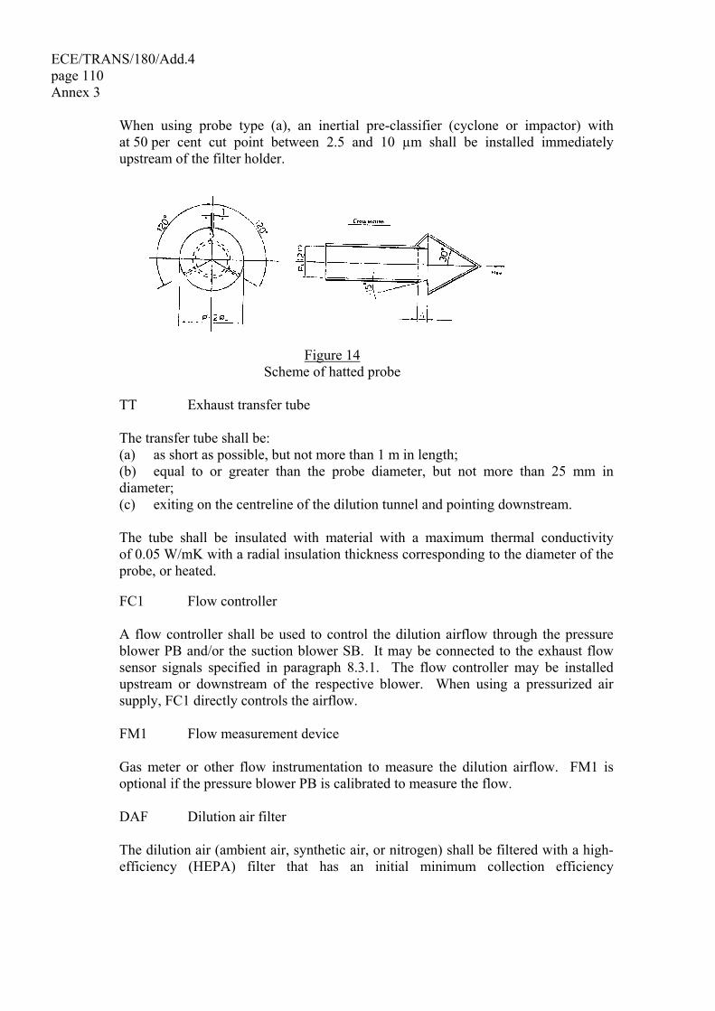
ECE/TRANS/180/Add.4 page 110 Annex 3 When using probe type (a), an inertial pre-classifier (cyclone or impactor) with
at 50 per cent cut point between 2.5 and 10 µm shall be installed immediately upstream of the filter holder.
Figure 14
Scheme of hatted probe TT Exhaust transfer tube The transfer tube shall be: (a) as short as possible, but not more than 1 m in length; (b) equal to or greater than the probe diameter, but not more than 25 mm in
diameter; (c) exiting on the centreline of the dilution tunnel and pointing downstream. The tube shall be insulated with material with a maximum thermal conductivity
of 0.05 W/mK with a radial insulation thickness corresponding to the diameter of the probe, or heated.
FC1 Flow controller A flow controller shall be used to control the dilution airflow through the pressure
blower PB and/or the suction blower SB. It may be connected to the exhaust flow sensor signals specified in paragraph 8.3.1. The flow controller may be installed upstream or downstream of the respective blower. When using a pressurized air supply, FC1 directly controls the airflow.
FM1 Flow measurement device Gas meter or other flow instrumentation to measure the dilution airflow. FM1 is
optional if the pressure blower PB is calibrated to measure the flow.
DAF Dilution air filter The dilution air (ambient air, synthetic air, or nitrogen) shall be filtered with a high-
efficiency (HEPA) filter that has an initial minimum collection efficiency
ECE/TRANS/180/Add.4 page 111 Annex 3
of 99.97 per cent. The dilution air shall have a temperature of ≥ 288 K (15 °C), and may be dehumidified.
FM2 Flow measurement device (fractional sampling type, figure 13 only) Gas meter or other flow instrumentation to measure the diluted exhaust gas flow.
FM2 is optional if the suction blower SB is calibrated to measure the flow. PB Pressure blower (fractional sampling type, figure 13 only) To control the dilution airflow rate, PB may be connected to the flow controllers FC1
or FC2. PB is not required when using a butterfly valve. PB may be used to measure the dilution airflow, if calibrated.
SB Suction blower (fractional sampling type, figure 13 only) SB may be used to measure the diluted exhaust gas flow, if calibrated. DT Dilution tunnel The dilution tunnel: (a) shall be of a sufficient length to cause complete mixing of the exhaust and
dilution air under turbulent flow conditions for a fractional sampling system, i.e. complete mixing is not required for a total sampling system;
(b) shall be constructed of stainless steel; (c) shall be at least 75 mm in diameter for the fractional sampling type; (d) is recommended to be at least 25 mm in diameter for the total sampling type; (e) may be heated to no greater than 325 K (52 °C) wall temperature; (f) may be insulated. PSP Particulate sampling probe (fractional sampling type, figure 13 only) The particulate sampling probe is the leading section of the particulate transfer tube
PTT (see paragraph A.3.2.7.) and: (a) shall be installed facing upstream at a point where the dilution air and exhaust
gas are well mixed, i.e. on the dilution tunnel DT centreline approximately 10 tunnel diameters downstream of the point where the exhaust enters the dilution tunnel;
(b) shall be 12 mm in minimum inside diameter; (c) may be heated to no greater than 325 K (52 °C) wall temperature by direct
heating or by dilution air pre-heating, provided the dilution air temperature does not exceed 325 K (52 °C) prior to the introduction of the exhaust into the dilution tunnel;
(d) may be insulated.
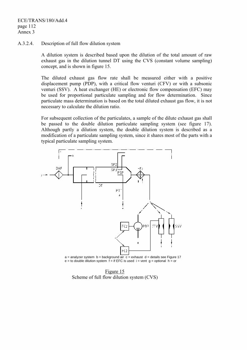
ECE/TRANS/180/Add.4 page 112 Annex 3 A.3.2.4. Description of full flow dilution system A dilution system is described based upon the dilution of the total amount of raw
exhaust gas in the dilution tunnel DT using the CVS (constant volume sampling) concept, and is shown in figure 15.
The diluted exhaust gas flow rate shall be measured either with a positive
displacement pump (PDP), with a critical flow venturi (CFV) or with a subsonic venturi (SSV). A heat exchanger (HE) or electronic flow compensation (EFC) may be used for proportional particulate sampling and for flow determination. Since particulate mass determination is based on the total diluted exhaust gas flow, it is not necessary to calculate the dilution ratio.
For subsequent collection of the particulates, a sample of the dilute exhaust gas shall
be passed to the double dilution particulate sampling system (see figure 17). Although partly a dilution system, the double dilution system is described as a modification of a particulate sampling system, since it shares most of the parts with a typical particulate sampling system.
a = analyzer system b = background air c = exhaust d = details see Figure 17 e = to double dilution system f = if EFC is used i = vent g = optional h = or
Figure 15
Scheme of full flow dilution system (CVS)
ECE/TRANS/180/Add.4 page 113 Annex 3
A.3.2.5. Components of figure 15 EP Exhaust pipe The exhaust pipe length from the exit of the engine exhaust manifold, turbocharger
outlet or after-treatment device to the dilution tunnel shall be not more than 10 m. If the system exceeds 4 m in length, then all tubing in excess of 4 m shall be insulated, except for an in-line smoke meter, if used. The radial thickness of the insulation shall be at least 25 mm. The thermal conductivity of the insulating material shall have a value no greater than 0.1 W/mK measured at 673 K. To reduce the thermal inertia of the exhaust pipe a thickness-to-diameter ratio of 0.015 or less is recommended. The use of flexible sections shall be limited to a length-to-diameter ratio of 12 or less.
PDP Positive displacement pump The PDP meters total diluted exhaust flow from the number of the pump revolutions
and the pump displacement. The exhaust system backpressure shall not be artificially lowered by the PDP or dilution air inlet system. Static exhaust backpressure measured with the PDP system operating shall remain within ± 1.5 kPa of the static pressure measured without connection to the PDP at identical engine speed and load. The gas mixture temperature immediately ahead of the PDP shall be within ± 6 K of the average operating temperature observed during the test, when no flow compensation (EFC) is used. Flow compensation is only permitted, if the temperature at the inlet to the PDP does not exceed 323 K (50 °C).
CFV Critical flow venturi CFV measures total diluted exhaust flow by maintaining the flow at chocked
conditions (critical flow). Static exhaust backpressure measured with the CFV system operating shall remain within ± 1.5 kPa of the static pressure measured without connection to the CFV at identical engine speed and load. The gas mixture temperature immediately ahead of the CFV shall be within ± 11 K of the average operating temperature observed during the test, when no flow compensation (EFC) is used.
SSV Subsonic venturi SSV measures total diluted exhaust flow by using the gas flow function of a subsonic
venturi in dependence of inlet pressure and temperature and pressure drop between venturi inlet and throat. Static exhaust backpressure measured with the SSV system operating shall remain within ± 1.5 kPa of the static pressure measured without connection to the SSV at identical engine speed and load. The gas mixture temperature immediately ahead of the SSV shall be within ± 11 K of the average operating temperature observed during the test, when no flow compensation (EFC) is used.
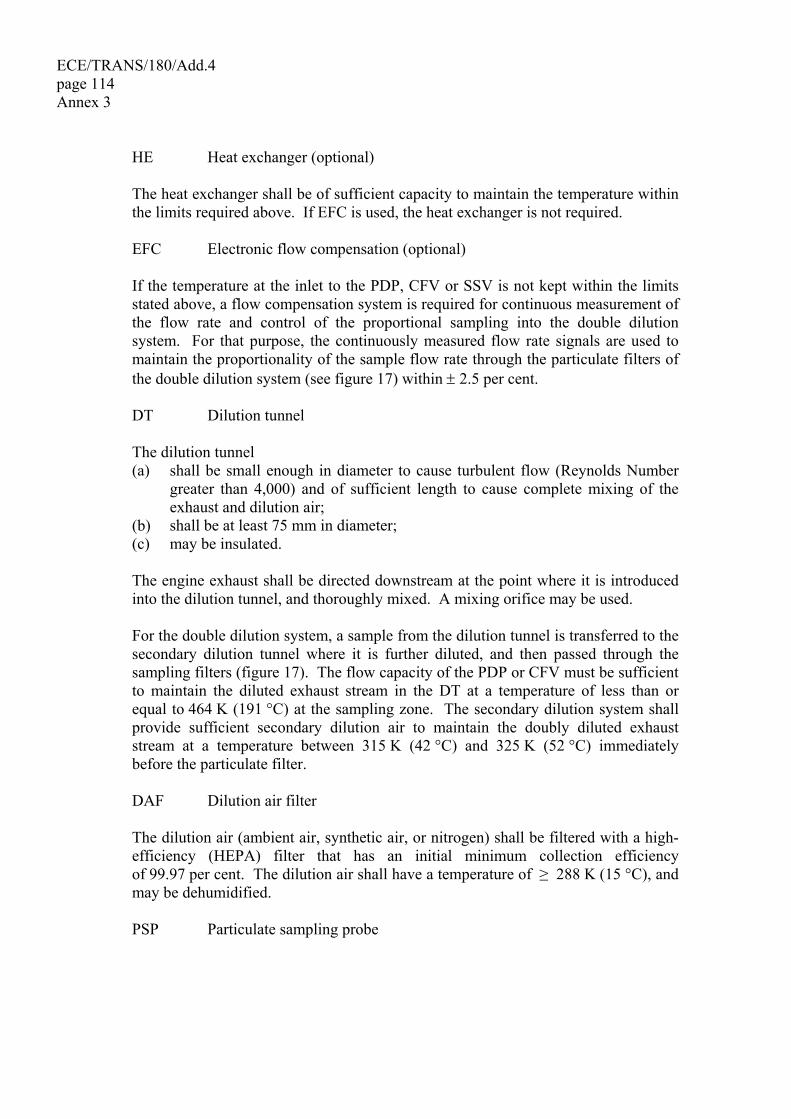
ECE/TRANS/180/Add.4 page 114 Annex 3 HE Heat exchanger (optional) The heat exchanger shall be of sufficient capacity to maintain the temperature within
the limits required above. If EFC is used, the heat exchanger is not required. EFC Electronic flow compensation (optional) If the temperature at the inlet to the PDP, CFV or SSV is not kept within the limits
stated above, a flow compensation system is required for continuous measurement of the flow rate and control of the proportional sampling into the double dilution system. For that purpose, the continuously measured flow rate signals are used to maintain the proportionality of the sample flow rate through the particulate filters of the double dilution system (see figure 17) within ± 2.5 per cent.
DT Dilution tunnel The dilution tunnel (a) shall be small enough in diameter to cause turbulent flow (Reynolds Number
greater than 4,000) and of sufficient length to cause complete mixing of the exhaust and dilution air;
(b) shall be at least 75 mm in diameter; (c) may be insulated. The engine exhaust shall be directed downstream at the point where it is introduced
into the dilution tunnel, and thoroughly mixed. A mixing orifice may be used. For the double dilution system, a sample from the dilution tunnel is transferred to the
secondary dilution tunnel where it is further diluted, and then passed through the sampling filters (figure 17). The flow capacity of the PDP or CFV must be sufficient to maintain the diluted exhaust stream in the DT at a temperature of less than or equal to 464 K (191 °C) at the sampling zone. The secondary dilution system shall provide sufficient secondary dilution air to maintain the doubly diluted exhaust stream at a temperature between 315 K (42 °C) and 325 K (52 °C) immediately before the particulate filter.
DAF Dilution air filter The dilution air (ambient air, synthetic air, or nitrogen) shall be filtered with a high-
efficiency (HEPA) filter that has an initial minimum collection efficiency of 99.97 per cent. The dilution air shall have a temperature of ≥ 288 K (15 °C), and may be dehumidified.
PSP Particulate sampling probe
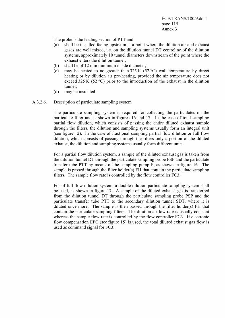
ECE/TRANS/180/Add.4 page 115 Annex 3
The probe is the leading section of PTT and (a) shall be installed facing upstream at a point where the dilution air and exhaust
gases are well mixed, i.e. on the dilution tunnel DT centreline of the dilution systems, approximately 10 tunnel diameters downstream of the point where the exhaust enters the dilution tunnel;
(b) shall be of 12 mm minimum inside diameter; (c) may be heated to no greater than 325 K (52 °C) wall temperature by direct
heating or by dilution air pre-heating, provided the air temperature does not exceed 325 K (52 °C) prior to the introduction of the exhaust in the dilution tunnel;
(d) may be insulated. A.3.2.6. Description of particulate sampling system The particulate sampling system is required for collecting the particulates on the
particulate filter and is shown in figures 16 and 17. In the case of total sampling partial flow dilution, which consists of passing the entire diluted exhaust sample through the filters, the dilution and sampling systems usually form an integral unit (see figure 12). In the case of fractional sampling partial flow dilution or full flow dilution, which consists of passing through the filters only a portion of the diluted exhaust, the dilution and sampling systems usually form different units.
For a partial flow dilution system, a sample of the diluted exhaust gas is taken from
the dilution tunnel DT through the particulate sampling probe PSP and the particulate transfer tube PTT by means of the sampling pump P, as shown in figure 16. The sample is passed through the filter holder(s) FH that contain the particulate sampling filters. The sample flow rate is controlled by the flow controller FC3.
For of full flow dilution system, a double dilution particulate sampling system shall
be used, as shown in figure 17. A sample of the diluted exhaust gas is transferred from the dilution tunnel DT through the particulate sampling probe PSP and the particulate transfer tube PTT to the secondary dilution tunnel SDT, where it is diluted once more. The sample is then passed through the filter holder(s) FH that contain the particulate sampling filters. The dilution airflow rate is usually constant whereas the sample flow rate is controlled by the flow controller FC3. If electronic flow compensation EFC (see figure 15) is used, the total diluted exhaust gas flow is used as command signal for FC3.

ECE/TRANS/180/Add.4 page 116 Annex 3
a = from dilution tunnel
Figure 16
Scheme of particulate sampling system
a = diluted exhaust from DT b = optional c = vent d = secondary dilution air
Figure 17 Scheme of double dilution particulate sampling system
A.3.2.7. Components of figures 16 (partial flow system only) and 17 (full flow system only) PTT Particulate transfer tube The particulate transfer tube shall not exceed 1,020 mm in length, and shall be
minimized in length whenever possible. The dimensions are valid for: (a) the partial flow dilution fractional sampling system from the probe tip to the
filter holder; (b) the partial flow dilution total sampling system from the end of the dilution
tunnel to the filter holder; (c) the full flow double dilution system from the probe tip to the entrance of the
secondary dilution tunnel.

ECE/TRANS/180/Add.4 page 117 Annex 3
The transfer tube: (a) may be heated to no greater than 325 K (52 °C) wall temperature; (b) may be insulated. SDT Secondary dilution tunnel (figure 17 only) The secondary dilution tunnel should have a minimum diameter of 75 mm, and
should be of sufficient length so as to provide a residence time of at least 0.25 s for the doubly diluted sample. The filter holder FH shall be located within 300 mm of the exit of the SDT.
The secondary dilution tunnel: (a) may be heated to no greater than 325 K (52 °C) wall temperature by direct
heating or by dilution air pre heating, provided the air temperature does not exceed 325 K (52 °C) prior to the introduction of the exhaust into the dilution tunnel;
(b) may be insulated. FH Filter holder The filter holder: (a) may be heated to no greater than 325 K (52 °C) wall temperature; (b) may be insulated. An inertial pre-classifier with a 50 per cent cut point between 2.5 µm and 10 µm
shall be installed immediately upstream of the filter holder, if an open tube sampling probe facing upstream is used.
P Sampling pump FC2 Flow controller A flow controller shall be used for controlling the particulate sample flow rate. FM3 Flow measurement device Gas meter or flow instrumentation to determine the particulate sample flow through
the particulate filter. It may be installed upstream or downstream of the sampling pump P.
FM4 Flow measurement device Gas meter or flow instrumentation to determine the secondary dilution airflow
through the particulate filter. BV Ball valve (optional)

ECE/TRANS/180/Add.4 page 118 Annex 3 The ball valve shall have an inside diameter not less than the inside diameter of the
particulate transfer tube PTT, and a switching time of less than 0.5 s.

ECE/TRANS/180/Add.4 page 119 Annex 4
Annex 4
DETERMINATION OF SYSTEM EQUIVALENCE The determination of system equivalency according to paragraph 5.1.1. shall be based on a 7 sample pair (or larger) correlation study between the candidate system and one of the accepted reference systems of this gtr using the appropriate test cycle(s). The equivalency criteria to be applied shall be the F-test and the two-sided Student t-test. This statistical method examines the hypothesis that the sample standard deviation and sample mean value for an emission measured with the candidate system do not differ from the sample standard deviation and sample mean value for that emission measured with the reference system. The hypothesis shall be tested on the basis of a 10 per cent significance level of the F and t values. The critical F and t values for 7 to 10 sample pairs are given in table 8. If the F and t values calculated according to the equation below are greater than the critical F and t values, the candidate system is not equivalent. The following procedure shall be followed. The subscripts R and C refer to the reference and candidate system, respectively: (a) Conduct at least 7 tests with the candidate and reference systems operated in
parallel. The number of tests is referred to as nR and nC. (b) Calculate the mean values Rx and Cx and the standard deviations sR and sC. (c) Calculate the F value, as follows:
2minor
2major
ss
F = (82)
(the greater of the two standard deviations sR or sC must be in the numerator) (d) Calculate the t value, as follows:
( ) ( )
( )RC
RCRC
2RR
2CC
RC 2
11 nnnnnn
snsn
xxt
+−+××
××−+×−
−= (83)
(e) Compare the calculated F and t values with the critical F and t values
corresponding to the respective number of tests indicated in table 8. If larger sample sizes are selected, consult statistical tables for 10 per cent significance (90 per cent confidence) level.
(f) Determine the degrees of freedom (df), as follows: for the F-test: df = nR –1 / nC –1 (84) for the t-test: df = nC + nR –2 (85)
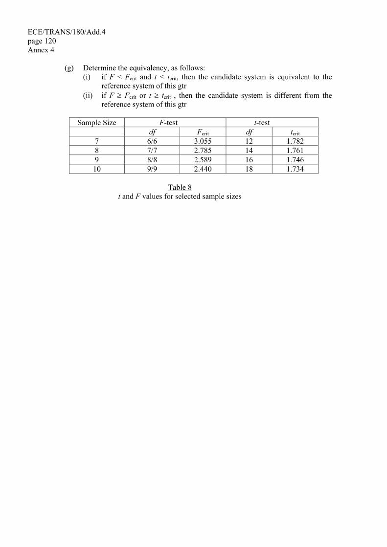
ECE/TRANS/180/Add.4 page 120 Annex 4 (g) Determine the equivalency, as follows: (i) if F < Fcrit and t < tcrit, then the candidate system is equivalent to the
reference system of this gtr (ii) if F ≥ Fcrit or t ≥ tcrit , then the candidate system is different from the
reference system of this gtr
Sample Size F-test t-test df Fcrit df tcrit 7 6/6 3.055 12 1.782 8 7/7 2.785 14 1.761 9 8/8 2.589 16 1.746 10 9/9 2.440 18 1.734
Table 8
t and F values for selected sample sizes
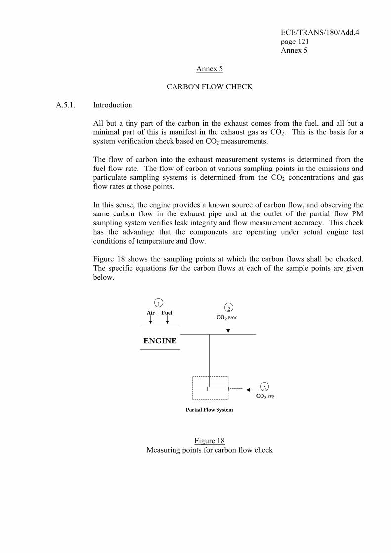
ECE/TRANS/180/Add.4 page 121 Annex 5
Annex 5
CARBON FLOW CHECK
A.5.1. Introduction All but a tiny part of the carbon in the exhaust comes from the fuel, and all but a
minimal part of this is manifest in the exhaust gas as CO2. This is the basis for a system verification check based on CO2 measurements.
The flow of carbon into the exhaust measurement systems is determined from the
fuel flow rate. The flow of carbon at various sampling points in the emissions and particulate sampling systems is determined from the CO2 concentrations and gas flow rates at those points.
In this sense, the engine provides a known source of carbon flow, and observing the
same carbon flow in the exhaust pipe and at the outlet of the partial flow PM sampling system verifies leak integrity and flow measurement accuracy. This check has the advantage that the components are operating under actual engine test conditions of temperature and flow.
Figure 18 shows the sampling points at which the carbon flows shall be checked.
The specific equations for the carbon flows at each of the sample points are given below.
Air Fuel
ENGINE
CO2 RAW
CO2 PFS
Partial Flow System
12
3
Figure 18
Measuring points for carbon flow check
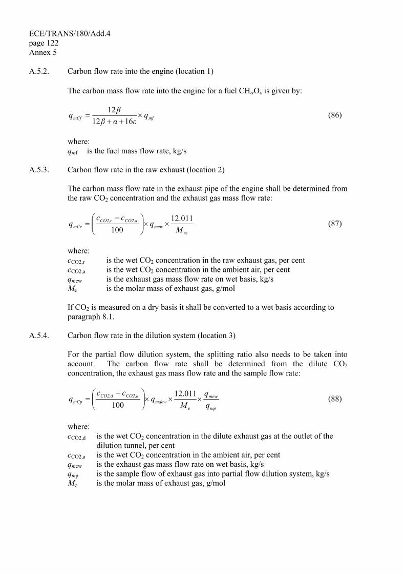
ECE/TRANS/180/Add.4 page 122 Annex 5 A.5.2. Carbon flow rate into the engine (location 1) The carbon mass flow rate into the engine for a fuel CHαOε is given by:
mfmCf qεαβ
βq ×++
=1612
12 (86)
where: qmf is the fuel mass flow rate, kg/s A.5.3. Carbon flow rate in the raw exhaust (location 2) The carbon mass flow rate in the exhaust pipe of the engine shall be determined from
the raw CO2 concentration and the exhaust gas mass flow rate:
re
mewaCO2,rCO2,
mCe Mq
ccq 12.011
100××⎟⎟
⎠
⎞⎜⎜⎝
⎛ −= (87)
where: cCO2,r is the wet CO2 concentration in the raw exhaust gas, per cent cCO2,a is the wet CO2 concentration in the ambient air, per cent qmew is the exhaust gas mass flow rate on wet basis, kg/s Me is the molar mass of exhaust gas, g/mol If CO2 is measured on a dry basis it shall be converted to a wet basis according to
paragraph 8.1. A.5.4. Carbon flow rate in the dilution system (location 3) For the partial flow dilution system, the splitting ratio also needs to be taken into
account. The carbon flow rate shall be determined from the dilute CO2 concentration, the exhaust gas mass flow rate and the sample flow rate:
mp
mew
emdew
aCO2,dCO2,mCp q
qM
qcc
q ×××⎟⎟⎠
⎞⎜⎜⎝
⎛ −=
12.011100
(88)
where: cCO2,d is the wet CO2 concentration in the dilute exhaust gas at the outlet of the
dilution tunnel, per cent cCO2,a is the wet CO2 concentration in the ambient air, per cent qmew is the exhaust gas mass flow rate on wet basis, kg/s qmp is the sample flow of exhaust gas into partial flow dilution system, kg/s Me is the molar mass of exhaust gas, g/mol
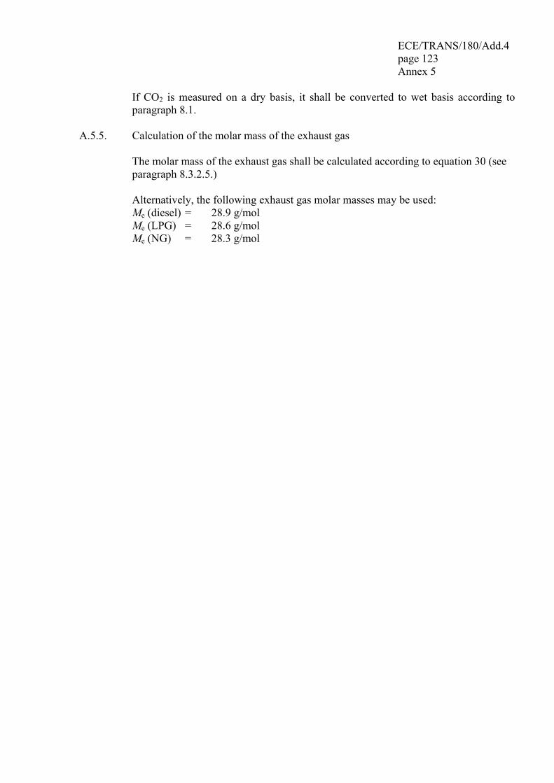
ECE/TRANS/180/Add.4 page 123 Annex 5
If CO2 is measured on a dry basis, it shall be converted to wet basis according to paragraph 8.1.
A.5.5. Calculation of the molar mass of the exhaust gas The molar mass of the exhaust gas shall be calculated according to equation 30 (see
paragraph 8.3.2.5.) Alternatively, the following exhaust gas molar masses may be used: Me (diesel) = 28.9 g/mol Me (LPG) = 28.6 g/mol Me (NG) = 28.3 g/mol
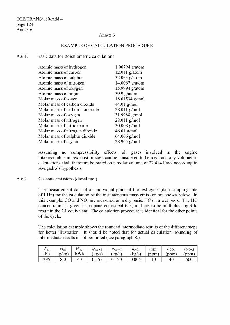
ECE/TRANS/180/Add.4 page 124 Annex 6
Annex 6
EXAMPLE OF CALCULATION PROCEDURE A.6.1. Basic data for stoichiometric calculations Atomic mass of hydrogen 1.00794 g/atom Atomic mass of carbon 12.011 g/atom Atomic mass of sulphur 32.065 g/atom Atomic mass of nitrogen 14.0067 g/atom Atomic mass of oxygen 15.9994 g/atom Atomic mass of argon 39.9 g/atom Molar mass of water 18.01534 g/mol Molar mass of carbon dioxide 44.01 g/mol Molar mass of carbon monoxide 28.011 g/mol Molar mass of oxygen 31.9988 g/mol Molar mass of nitrogen 28.011 g/mol Molar mass of nitric oxide 30.008 g/mol Molar mass of nitrogen dioxide 46.01 g/mol Molar mass of sulphur dioxide 64.066 g/mol Molar mass of dry air 28.965 g/mol Assuming no compressibility effects, all gases involved in the engine
intake/combustion/exhaust process can be considered to be ideal and any volumetric calculations shall therefore be based on a molar volume of 22.414 l/mol according to Avogadro’s hypothesis.
A.6.2. Gaseous emissions (diesel fuel) The measurement data of an individual point of the test cycle (data sampling rate
of 1 Hz) for the calculation of the instantaneous mass emission are shown below. In this example, CO and NOx are measured on a dry basis, HC on a wet basis. The HC concentration is given in propane equivalent (C3) and has to be multiplied by 3 to result in the C1 equivalent. The calculation procedure is identical for the other points of the cycle.
The calculation example shows the rounded intermediate results of the different steps
for better illustration. It should be noted that for actual calculation, rounding of intermediate results is not permitted (see paragraph 8.).
Ta,i (K)
Ha,i (g/kg)
Wact kWh
qmew,i (kg/s)
qmaw,i (kg/s)
qmf,i (kg/s)
cHC,i (ppm)
cCO,i (ppm)
cNOx,i (ppm)
295 8.0 40 0.155 0.150 0.005 10 40 500

ECE/TRANS/180/Add.4 page 125 Annex 6
The following fuel composition is considered:
Component Molar ratio per cent mass H α = 1.8529 wALF = 13.45 C β = 1.0000 wBET = 86.50 S γ = 0.0002 wGAM = 0.050 N δ = 0.0000 wDEL = 0.000 O ε = 0.0000 wEPS = 0.000
Step 1: Dry/wet correction (paragraph 8.1.): Equation (11): kf = 0.055584 x 13.45 - 0.0001083 x 86.5 - 0.0001562 x 0.05 = 0.7382
Equation (8): kw,a= 1.0081,0000.7382
0.1480.00581.2434773.4
0.1480.00513.45111.1281.2434
1 ×⎟⎟⎟⎟
⎠
⎞
⎜⎜⎜⎜
⎝
⎛
××+×+
××+×− = 0.9331
Equation (7): cCO,i (wet) = 40 x 0.9331 = 37.3 ppm cNOx,i (wet) = 500 x 0.9331 = 466.6 ppm Step 2: NOx correction for temperature and humidity (paragraph 8.2.1.):
Equation (18): 832.0000,1
00.8698.15Dh, +
×=k = 0.9576
Step 3: Calculation of the instantaneous emission of each individual point of the
cycle (paragraph 8.3.2.4.): Equation (25): mHC,i = 10 x 3 x 0.155 = 4.650 mCO,i = 37.3 x 0.155 = 5.782 mNox,I = 466.6 x 0.9576 x 0.155 = 69.26 Step 4: Calculation of the mass emission over the cycle by integration of the
instantaneous emission values and the u values from table 4 (paragraph 8.3.2.4.): The following calculation is assumed for the WHTC cycle (1,800 s) and the same
emission in each point of the cycle.
Equation (25): mHC = 0.000479 x ∑=
1800
1i4.650 = 4.01 g/test
mCO = 0.000966 x ∑=
1800
1i5.782 = 10.05 g/test
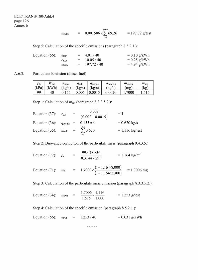
ECE/TRANS/180/Add.4 page 126 Annex 6
mNOx = 0.001586 x ∑=
1800
1i69.26 = 197.72 g/test
Step 5: Calculation of the specific emissions (paragraph 8.5.2.1.): Equation (56): eHC = 4.01 / 40 = 0.10 g/kWh eCO = 10.05 / 40 = 0.25 g/kWh eNOx = 197.72 / 40 = 4.94 g/kWh A.6.3. Particulate Emission (diesel fuel)
pb (kPa)
Wact (kWh)
qmew,i (kg/s)
qmf,i (kg/s)
qmdw,i (kg/s)
qmdew,i (kg/s)
muncor (mg)
msep (kg)
99 40 0.155 0.005 0.0015 0.0020 1.7000 1.515 Step 1: Calculation of medf (paragraph 8.3.3.5.2.):
Equation (37): rd,i = ⎟⎠⎞⎜
⎝⎛ − 0.00150.002
0.002 = 4
Equation (36): qmedf,i = 0.155 x 4 = 0.620 kg/s
Equation (35): medf = ∑=
1800
1i0.620 = 1,116 kg/test
Step 2: Buoyancy correction of the particulate mass (paragraph 9.4.3.5.)
Equation (72): ρa = 2953144.8
28.83699×
× = 1.164 kg/m3
Equation (71): mf = ( )( )300,2164.11
000,8164.117000.1−−
× = 1.7006 mg
Step 3: Calculation of the particulate mass emission (paragraph 8.3.3.5.2.):
Equation (34): mPM = 1,0001,116
1.5151.7006
× = 1.253 g/test
Step 4: Calculation of the specific emission (paragraph 8.5.2.1.): Equation (56): ePM = 1.253 / 40 = 0.031 g/kWh
- - - - -