GLOBAL PX/RX/LP - Swegon · GLOBAL PX/RX/LP Applicable to program versions TAC5 – Version DT...
60
GLOBAL RX TOP Operation and maintenance instructions GLOBAL PX/RX/LP Applicable to program versions TAC5 – Version DT 2.8.2 & DG 2.7.0 GLOBAL PX GLOBAL LP FW GLOBAL PX TOP FW GLOBAL RX GLOBAL PX FW
Transcript of GLOBAL PX/RX/LP - Swegon · GLOBAL PX/RX/LP Applicable to program versions TAC5 – Version DT...

GLOBAL RX TOP
Operation and maintenance instructions
GLOBAL PX/RX/LP
Applicable to program versions TAC5 – Version DT 2.8.2 & DG 2.7.0
GLOBAL PX
GLOBAL LP FW
GLOBAL PX TOP FW
GLOBAL RX
GLOBAL PX FW

Operation and maintenance instructions – v2.8.2 & 2.7.0
1.0 Safety precautions
2.0 Symbols and abbreviations
3.0 Product Overview
4.0 Wiring Overview
5.0 Functions
6.0 Commissioning 6.1 Commissioning with Touchscreen interface
7.0 Preventive maintenance
8.0 Troubleshooting
9.0 Parameters/Commissioning Sheet
4
6
7
12
18
24
38
40
56
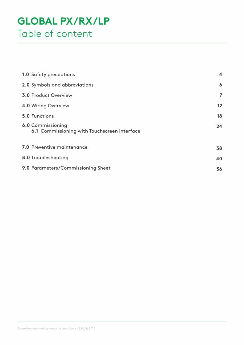
GLOBAL PX/RX/LPTable of content

4 Operation and maintenance instructions – v2.8.2 & 2.7.0
1.0 Installation manualApplicable for the following units
EXCHANGER SIZE HANDING FAN
GLOBAL PXCounterflow
800 Left / Right Backward
800FW Left / Right Forward (FW)
1200 Left / Right Backward
1200FW Left / Right Forward (FW)
2000 Left / Right Backward
2000FW Left / Right Forward (FW)
3000 Left / Right Backward
3000FW Left / Right Forward (FW)
4000 Left / Right Backward
4000FW Left / Right Forward (FW)
5000 Left / Right Backward
5000FW Left / Right Forward (FW)
6000 Left / Right Backward
6000FW Left / Right Forward (FW)
GLOBAL PX TOP
Counterflow
800FW Right Forward (FW)
1200FW Right Forward (FW)
2000FW Right Forward (FW)
GLOBAL RXRotary
05 Left / Right Backward
08 Left / Right Backward
10 Left / Right Backward
12 Left / Right Backward
13 Left / Right Backward
14 Left / Right Backward
16 Left / Right Backward
20 Left / Right Backward
24 Left / Right Backward
26 Left / Right Backward
GLOBAL LPCounterflow
450FW Left / Right Backward
600FW Left / Right Forward (FW)
1000FW Left / Right Forward (FW)
1600FW Left / Right Forward (FW)
2000FW Left / Right Forward (FW)
GLOBAL RXTOP
Rotary
05 Left / Right Backward
08 Left / Right Backward
10 Left / Right Backward
12 Left / Right Backward
13 Left / Right Backward
14 Left / Right Backward
16 Left / Right Backward

5Operation and maintenance instructions – v2.8.2 & 2.7.0
DisclaimerDanger/Warning/Caution
• All staff concerned shall acquaint themselves with these instructions before beginning any work on the unit. Any damages to the unit or its components caused by improper handling or misuse by the purchaser or the installer cannot be considered subject to guarantee if these instructions have not been followed correctly.
• Make sure that the power supply to the unit is disconnected before performing any maintenance or electrical work!
• All electrical connections must be carried out by an authorized installer and in accordance with local rules and controls.
• Although the mains supply to the unit has been disconnected there is still risk for injury due to rotating parts that have not come to a complete standstill.
• Beware of sharp edges during mounting and maintenance. Make sure that a proper lifting device is used. Use protective clothing.
• Unit should always be operated with closed doors and panels.
• If the unit is installed in a cold place make sure that all joints are covered with insulation and are well taped.
• Duct connections/duct ends should be covered during storage and installation, in order to avoid condensation inside of the unit.
• Check that there are no foreign objects in unit, ducting system or functional sections.
RANGE OF APPLICATIONThe GLOBAL units are designed for use in comfort ventilation applications.
Depending on the variant selected, GLOBAL units can be utilised in buildings such as office buildings, schools, day nurseries,public buildings, shops, residential buildings, etc.
GLOBAL units equipped with plate heat exchangers (PX) can also be used for the ventilation of moderately humid buildings; however not where the humidity is continuously high, such as in indoor swimming baths, saunas, spas or wellness centres.
Please do contact us if you have a need for a unit that is suited for such an application.
HOW TO READ THIS DOCUMENT Please make sure that you have read and understood the safety precautions below.
For new users, please read chapter 2 where the Symbols and Abbreviations used for GLOBAL are listed and Chapter 5 where the operating principles of a GLOBAL air handling unit are described. The commissioning of the unit is described in chapter 6.
The commissioning chapter is divided based on what device (Remote Control, Graphical Remote Control or App) is used to control the unit. Simply go to the sub chapter, relevant for your device and the base setup for the operating mode which will be used to control the unit.

6 Operation and maintenance instructions – v2.8.2 & 2.7.0
2.0 Symbols and abbreviations
BWBACKWARD
CURVED FANFW
FORWARD CURVED FAN
BF BAG FILTER PF PLEATED FILTER
RXROTARY HEAT EXCHANGER
PXPLATE HEAT EXCHANGER
WARNING
Must be connected by a qualified Electrician.Warning! Hazardous voltage.
OUTDOOR AIR Air from outdoor to the AHU
SUPPLY AIR Air from the AHU to the building
EXTRACT AIR Air from the building to the AHU
EXHAUST AIR Air from the AHU to outdoor
COOLING COIL BA-
NV / KWHEATING COIL
(WATER / ELECTRICAL)
SILENCER GD CTmMOTORIZED
DAMPER
PRESSURE SENSOR P TxTEMPERATURE SENSOR
Nr = x (1,2,3…)
SLIP CLAMP SC MSFLEXIBLE
CONNECTION
CIRCULAR DUCT CONNECTION ER For inlet SR For outlet
7Operation and maintenance instructions – v2.8.2 & 2.7.0
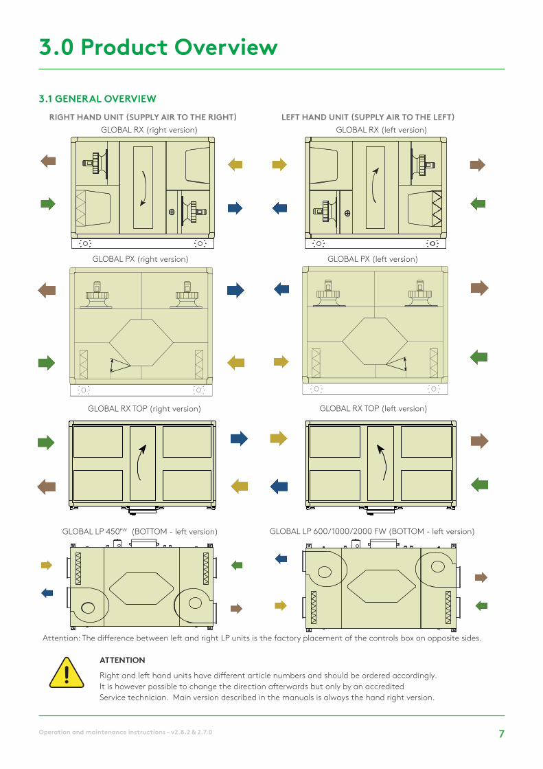
3.1 GENERAL OVERVIEW
ATTENTION
Right and left hand units have different article numbers and should be ordered accordingly. It is however possible to change the direction afterwards but only by an accredited Service technician. Main version described in the manuals is always the hand right version.
3.0 Product Overview
RIGHT HAND UNIT (SUPPLY AIR TO THE RIGHT) LEFT HAND UNIT (SUPPLY AIR TO THE LEFT)
Attention: The difference between left and right LP units is the factory placement of the controls box on opposite sides.
GLOBAL RX (right version) GLOBAL RX (left version)
GLOBAL PX (right version) GLOBAL PX (left version)
GLOBAL LP 450FW (BOTTOM - left version) GLOBAL LP 600/1000/2000 FW (BOTTOM - left version)
GLOBAL RX TOP (right version) GLOBAL RX TOP (left version)

8 Operation and maintenance instructions – v2.8.2 & 2.7.0
1. Main switch for power supply AHU
2. Main switch for power supply electrical coils (both internal pre-hating and post-heating)
3. Centralized wiring box with TAC5 controller
4. Supply fan
5. Extract fan
6. Kit CA -airflow measurement (option)
7. F7 filter at outdoor air side (bag or pleated)
8. M5 filter on extract air side (F7 as accessory)
9. Heat exchanger (Plate or Rotary)
10. Modulating 100% by-pass (PX units only)
11. Drain pan and drain pipe (PX units only)
12. Pre-heating electrical antifrost coil (PX units only)
13. Internal post-heating water or electrical coil (accessory)
14. Motorized damper (at outdoor air side - accessory)
15. Motorized damper (at exhaust air side - accessory)
16. Access panel (LP units only)
17. Flexible connection(accessory)
18. Slip Clamps (accessory)
19. Water connection for postheating (accessory)
1, 2 and 3 must be installed by an accredited electrician
Note: internal electrical coils, motorized dampers, internal fan-pressure sensors, flexible connections and slip-clamps have to be ordered initially and are all pre-mounted and factory wired. Internal heating water-coil accessory is pre-mounted but has to be hydraulically and electrically connected by the installer.
GLOBAL PX
GLOBAL LPFW GLOBAL PX TOPFW

9Operation and maintenance instructions – v2.8.2 & 2.7.0
Duct connections: see drawings downloadable on our website.
EXCHANGER SIZE AIR VOLUME A [mm] B [mm] C [mm] Weight [kg]
GLOBAL PXCounterflow
800 (FW) 800 m³/h 222 l/s 1206 755 1231 250
1200 (FW) 1200 m³/h 333 l/s 1210 1155 1235 310
2000 (FW) 2000 m³/h 560 l/s 1636 1175 1361 450
3000 (FW) 3000 m³/h 833 l/s 1636 1545 1361 490
4000 (FW) 4000 m³/h 1111 l/s 1636 1915 1365 640
5000 (FW) 5000 m³/h 1389 l/s 1636 2205 1765 780
6000 (FW) 6000 m³/h 1667 l/s 1636 2205 1765 810
GLOBAL LPCounterflow
450 FW 450 m³/h 125 l/s 1100 710 360 85
600 FW 600 m³/h 167 l/s 1490 1000 320 135
1000 FW 1000 m³/h 278 l/s 1550 1150 400 190
1600 FW 1600 m³/h 444 l/s 1550 1790 400 245
2000 FW 2000 m³/h 556 l/s 1700 2090 400 300
3.2 AIR VOLUMES AND DIMENSIONS
GLOBAL PX (FW) GLOBAL LPFW

10 Operation and maintenance instructions – v2.8.2 & 2.7.0
1. Main switch for power supply AHU
2. Main switch for power supply electrical coil
3. Centralized wiring box with TAC5 controller
4. Supply fan
5. Extract fan
6. Kit CA -airflow measurement (option)
7. F7 filter at outdoor air side
8. M5 filter on extract air side
9. Heat exchanger (Rotary)
13. Internal post-heating water or electrical coil (accessory)
14. Motorized damper (at outdoor air side - accessory)
15. Motorized damper (at exhaust air side - accessory)
17. Flexible connection(accessory)
18. Slip Clamps (accessory)
19. Water connection for postheating (accessory)
1, 2 and 3 must be installed by an accredited electrician
Note: internal electrical coils, motorized dampers, internal fan-pressure sensors, flexible connections and slip-clamps have to be ordered initially and are all pre-mounted and factory wired. Internal heating water-coil accessory is pre-mounted but has to be hydraulically and electrically connected by the installer.
GLOBAL RX TOP GLOBAL RX
1
2
3
4
5
6
6
7
8
9
13
15
14
17
17
18
18
19

11Operation and maintenance instructions – v2.8.2 & 2.7.0
Duct connections: see drawings downloadable on our website.
EXCHANGER SIZE AIR VOLUME A [mm] B [mm] C [mm] Weight [kg]
GLOBAL RX TOP
Rotary
05 1100 m³/h 305l/s 815 1530 1315 295
08 1500 m³/h 416l/s 815 1530 1315 310
10 1600 m³/h 440l/s 885 1680 1465 365
12 2000 m³/h 555l/s 885 1680 1465 365
13 2300 m³/h 640l/s 995 1680 1465 390
14 2800 m³/h 780l/s 1182 1680 1465 400
16 3200 m³/h 830l/s 1182 1680 1465 410
GLOBAL RXRotary
05 1200 m³/h 330 l/s 815 1530 1315
08 1600 m³/h 440 l/s 815 1530 1315
10 1800 m³/h 500 l/s 885 1680 1465
12 2300 m³/h 640 l/s 885 1680 1465
13 2900 m³/h 805 l/s 995 1680 1465
14 3100 m³/h 860 l/s 1182 1680 1465
16 3400 m³/h 940 l/s
20
24
26
3.3 AIR VOLUMES AND DIMENSIONS
GLOBAL RX (TOP)

12 Operation and maintenance instructions – v2.8.2 & 2.7.0
MAIN CONTROL BOARD TAC 5 DG
GLOBAL PX & LP FWCT = output to CT actuator(s) (option - prewired) IN1 = Master selection
BYPASS = output to bypass actuator (prewired) IN2 = dPa (pressostat digital input)
AL1 = ALARM OUTPUT (230V/5A) IN3 = Fire alarm
B- / A+ / GND / +12V = connection to HMI IN4 = Bypass open / Stop heat recovery
K1: CA MODE = m³/h K1 IN5 = Real time clock auto/manu
LS / CPs MODE = START/STOP IN6 = ON/OFF post heating (NV/KWout)
TQ MODE = %torque K1 IN7 = ON/OFF SUPPLY if fire alarm
K2: CA MODE = m³/h K2 IN8 = ON/OFF EXHAUST if fire alarm
LS / CPs MODE = 0-10V INPUT IN9 = BOOST Airflow
TQ MODE = %torque K2 IN12 = input for modulating bypass position
K3: CA MODE = m³/h K3 OUT1 = 0-10V OUTPUT (airflow / pressure)
LS / CPs MODE = % ON K3 or 0-10 V INPUT OUT2 = 0-10V OUTPUT (airflow / pressure)
TQ MODE = %torque K3 OUT4 = 0-10V OUTPUT internal post heating (NV)
T1 = from outdoors T° sensor (prewired) OUT5 = 24VDC / 1A
T2 = from indoors T° sensor (prewired) O.R.1 (output relay 1 - SAT3) = PRESSURE ALARM
T3 = to outdoors T° sensor (prewired) O.R.2 (output relay 2 - SAT3) = FAN ON
T4 = NV anti freeze protection T° sensor (option - prewired) O.R.3 (output relay 3 - SAT3) = WATER PUMP (for NV option)
T5 = supply T° sensor for NV/KWout regulation (option - prewired) O.R.4 (output relay 4 - SAT3) = BYPASS STATUS
PR1 = ΔPa from supply inlet fan (only on PX - option) KWin = output for KWin capacity control (option - prewired)
PR3 = ΔPa from exhaust inlet fan (only on PX - option) KWout = output for KWout power regulation (option - prewired)
GLOBAL PX & GLOBAL LPFW (1000/1600/2000) CID025000
4.0 Wiring Overview

13Operation and maintenance instructions – v2.8.2 & 2.7.0
GLOBAL RX & LP FWCT : output to CT actuator(s) (option - prewired) IN1 = Master selection
KWout = output for KWout power regulation (option - prewired) IN2 = dPa (pressostat digital input)
AL1 = ALARM OUTPUT (230V/5A) IN3 = Fire alarm
B- / A+ / GND / +12V = connection to HMI IN4 = Bypass open / Stop heat recovery
K1: CA MODE = m³/h K1 IN5 = Real time clock auto/manu
LS / CPs MODE = START/STOP IN6 = ON/OFF post heating (NV/KWout)
TQ MODE = %torque K1 IN7 = ON/OFF SUPPLY if fire alarm
K2: CA MODE = m³/h K2 IN8 = ON/OFF EXHAUST if fire alarm
LS / CPs MODE = 0-10V INPUT IN9 = BOOST Airflow
TQ MODE = %torque K2 IN12 = input pulse from heat exchanger magnet (prewired)
K3: CA MODE = m³/h K3 OUT1 = 0-10V OUTPUT (airflow / pressure)
LS / CPs MODE = % ON K3 or 0-10 V INPUT OUT2 = 0-10V OUTPUT (airflow / pressure)
TQ MODE = %torque K3 OUT4 = 0-10V OUTPUT internal post heating (NV)
T1 = from outdoors T° sensor (prewired) OUT5 = 24VDC / 1A
T2 = from indoors T° sensor (prewired) O.R.1 (output relay 1 - SAT3) = PRESSURE ALARM
T4 = NV anti freeze protection T° sensor (option - prewired) O.R.2 (output relay 2 - SAT3) = FAN ON
T5 = supply T° sensor for NV/KWout regulation (option - prewired) O.R.3 (output relay 3 - SAT3) = WATER PUMP (for NV option)
PR1 = ΔPa from supply inlet fan (only on RX - option) O.R.4 (output relay 4 - SAT3) = BYPASS STATUS
PR3 = ΔPa from exhaust inlet fan (only on RX - option) R-GND: output for heat exchanger wheel speed command (prewired)
GLOBAL RX (TOP) AND GLOBAL LPFW (450/600) CID026001
MAIN CONTROL BOARD TAC 5 DT

14 Operation and maintenance instructions – v2.8.2 & 2.7.0
4.1 CIRCUIT BOARD SAT 3
The SAT3 circuit board is used for extra functions for which inputs and outputs are not included as standard in the control unit of the air handling unit. All outputs are normally open (N.O.). Maximal load: 230VAC – 4A. The circuit board SAT3 allows for signalling of the following by means of a potential- free contact (Fig.2)
• Fan status
• Differential pressure alarm.
• General alarm
• Bypass status
• Circulation pump
Installation
SAT3 must be plugged into the control board circuit (see fig.1).
Attention: The SAT3 must be plugged in before the circuit is powered. SAT must be plugged in correctly, wrong positioning can damage both circuits permanently.
Fig. 2
Fig. 4
4.2 CIRCUIT BOARD SAT BA/KW
SAT TAC5 BA/KW is a satellite circuit designed to be fitted on the main control board. It permits control of external coils.
Installation
The SAT BA/KW must be plugged into the control board circuit (see Fig.3).
Attention: The SAT TAC5 BA/KW must be plugged in before the circuit is powered. SAT must be plugged in correctly, wrong positioning can damage both circuits permanently.
Wiring
The terminals of the SAT BA/KW are displayed in fig.4
WP WP = Circulation pump (contact closed for cooling / heating demand. max. 30 V-2 A)
OUT7 = 0-10 V output to control heating or change over coil.
OUT8 = 0-10 V output to control cooling coil
OUT9 = Output to control electrical coil
T°7 = Heating coil frost protection sensor (T7)
T°8 = Cooling coil frost protection sensor (T8)
IN10 = boosted cooling OFF, (to boost external post heating coil use IN6)
IN11 = Input cooling/heating (open = heating, closed = cooling)
Fig. 1
Fig. 3

15Operation and maintenance instructions – v2.8.2 & 2.7.0
4.4 INTERNAL WIRING DIAGRAM GLOBAL PX

16 Operation and maintenance instructions – v2.8.2 & 2.7.0
4.5 INTERNAL WIRING DIAGRAM GLOBAL RX (TOP)

17Operation and maintenance instructions – v2.8.2 & 2.7.0
4.6 INTERNAL WIRING DIAGRAM GLOBAL LPFW

18 Operation and maintenance instructions – v2.8.2 & 2.7.0
5.1 OPERATING MODE
There are five main operating modes. The operating mode determines how the airflow or the fan torque is modulated. The default operating mode is Constant Airflow regulation (CA). Exceptions are units equipped with backwards fans without the Constant Air (CA) Kit or if Constant Torque (TQ) mode has been selected in the product setup menu, in both cases it is the fan torque that will be controlled and modulated.
5.0 Functions
In all the operating modes, the supply fan(s) will operate as per the assigned mode and parameters. The exhaust fan(s) will operate according to the chosen percentage of the supply fan (%EXH/SUP ratio). The five main operating modes are:
• 1 - Constant Airflow regulation (CA): Flow regulation involves operating the air handling unit to keep the pre-set airflow constant. The speed of the fans is automatically regulated to provide correct airflow even if the filters begin to become clogged, air terminals are blocked, etc. Constant airflow is advantageous, since the airflow always is exactly as it was from the beginning. It should however be noted that everything that increases the pressure drop in the ventilation system, such as blocking of air terminals and dust accumulating in filters, causes the fans to run at a higher speed. This results in higher power consumption and may also cause discomfort in the form of noise. There are three airflow setpoints to be configured by the user (m³h K1, m³h K2, m³h K3).
• 2 - Constant torque regulation (TQ): 3 constant torque setpoints to be configured by the user (%TQ K1, %TQ K2, %TQ K3). The setpoint is configured in % of the maximal torque. The constant torque regulation (TQ) allows to vary the fan speed automatically, to provide a variable airflow for demand controlled systems (DCV). This allows for demand controlled fan operation or fan optimisation by a BMS system, mostly used in multi zone systems. This operation mode can partially replace the constant pressure regulation (CP) when a duct pressure sensor hasn’t been installed.
• 3 - Demand control 0-10 (LS) : The airflow is controlled by a 0-10 V signal. The control signal is connected to terminals K2&GND. The assigned supply airflow is set as a percentage of a linear 0-10 V signal. The user defines the link with 4 parameters: Vmin, Vmax, m³h Vmin and m³h Vmax, applied to the following diagram. The demand control mode (LS) is also available for modulating fan torque instead of airflow (relevant for backwards fans units without Kit CA). The principle is identical to the LS Mode operation with the difference that Vmin and Vmax are connected to a %TQ instead of m³/h.
• 4 - Constant pressure regulation (CP) : The airflow automatically varies to provide constant pressure in the ducting system. This type of regulation is also called VAV regulation (Variable Air Volume).
CPs on supply: the airflow of the supply fan(s) is modulated to maintain a certain pressure Setting constant. The pressure is measured by a pressure sensor located in the supply air duct. CPs on exhaust: the airflow of the exhaust fan(s) is modulated to maintain a certain pressure Setting constant. The pressure is measured by a pressure sensor located in the supply air duct.
• 5 - MODE OFF : This stops the AHU

19Operation and maintenance instructions – v2.8.2 & 2.7.0
• Internal electric coil
• Internal hydraulic coi
• External electric coil
• External hydraulic coil
5.2 TEMPERATURE REGULATION
5.3 FREE COOLING (RX AND PX)
There are several options available on GLOBAL units to ensure a comfortable temperature. The options are controlled either via supply or extract air temperature.
The free cooling function uses the lower temperature of the outside air to cool the building.
Free cooling is realized by means of the integrated 100% modulating bypass of the heat exchanger (PX) or the stepless motor control of the rotary heat exchanger (RX). The optional output O.R.4 on the SAT3 relay indicates the position of the bypass. The contact will open if the bypass is fully closed, or close if the bypass is fully or partially open.
The bypass (PX) or the rotary heat exchanger (RX) can be configured as on/off or modulating. This is configured in ADVANCED SETUP. In modulating mode, the temperature is configured in the base setup and the position of the bypass/stepless motor will modulate in order to maintain the setpoint. The free cooling function is activated automatically. An on/off bypass / stepless motor operates according to the logic below:
Free cooling STARTS if the following conditions are TRUE :
These Settings can be configured in ADVANCED SETUP
Free cooling STOPS if one of the following conditions is TRUE :
Extract Air Temperature (Comfort on T2)
The default temperature regulation can be changed to Extract temperature regulation via the advanced setup. The extract air temperature is measured on sensor T2. Extract air regulation involves keeping a constant temperature in the extract air duct (premises), by regulating the supply air temperature. This provides a uniform temperature in the premises regardless of the load. The internal sensor T2 can be replaced with the optional external room temperature sensor (CID370042).
Temperature sensor positioning :
Post-heating options : Post-cooling :
• The outdoor temperature (sensor T1) is lower than the extract air temperature (sensor T2)
• The outdoor temperature (sensor T1) is higher than 15°C.
• The extract air temperature (sensor T2) is higher than 22°C.
• The outdoor temperature (sensor T1) is higher than the extract air temperature (sensor T2).
• The outdoor temperature (sensor T1) is lower than 14°C.
• The extract air temperature (sensor T2) is lower than 20°C.
Supply Air Temperature (Comfort on T5)
Supply temperature regulation is the default setting. This involves keeping a constant supply air temperature without consideration to the load in the premises. The supply air temperature is measured on sensor T5.
• External coil
20 Operation and maintenance instructions – v2.8.2 & 2.7.0
5.5 CHANGE OVER FUNCTION
The TAC5 controller allows for the control of both cooling and heating coil. Both coils are equipped with their motorised 3-way valves. The offset between the measured temperature (supply air or extract air, to be configured) and the setpoint will determine if heating or cooling is automatically activated. When the unit is equipped with both a cooling and a heating coil, only one setpoint has to be configured: Comfort temperature. The neutral band prevents the cooling and heating systems from counteracting each other. The high neutral band is added to the comfort setpoint for the activation of the cooling function and the low neutral band is subtracted from the comfort setpoint for the activation of the heating function. Both high and low neutral bands have to be configured in the advanced setup.
4 PIPE AUTOMATIC CHANGE OVER
5.4 COOLING RECOVERY (RX ONLY)
Cooling recovery STARTS if the following condition is TRUE :• The outdoor temperature (sensor T1) is higher than the extract air temperature (sensor T2).
The cooling recovery function uses the lower extract air temperature to cool down the fresh air. The function is not configurable. If there is a cooling load in the building and the temperature in the extract air is lower than the outdoor air temperature, the heat exchanger shall be automatically controlled to operate at maximal speed. The temperature setpoint is configured in the base setup and the rotary heat exchanger will modulate in order to maintain the setpoint. The cooling recovery operates according to the logic below:

21Operation and maintenance instructions – v2.8.2 & 2.7.0
• 1 - Reduced supply air flow : The heat exchanger is supplied with a frost protection sensor on the exhaust air (T3). If the exhaust air temperature (T3) is >1°C and <+5°C : • In mode CA and LS, the supply air flow will modulate between 100% and 33% (AFlow) of the setpoint (AFn) • In mode CPs, the supply air pressure will modulate between 100% and 50% (AFlow) of the setpoint (AFn) If the exhaust air temperature (T3) is <1°C, the supply air fans will stop until the exhaust air temperature (T3) is >2°C for 5 minutes.
• 2 - Modulating bypass : The modulating bypass is controlled by the exhaust temperature sensor (T3). If: • Exhaust temperature (T3) >+1°C: bypass closed or controlled by free cooling function • Exhaust temperature (T3) ≤ +1°C: bypass will modulate for the exhaust temperature (T3) to exceed +1°C. The corresponding supply air temperature will drop due to a lower airflow through the heat exchanger
• 3 - Electrical preheating coil (accessory) : If an electrical pre-heating coil (KWin) is installed and configured, the pre-heating coil (KWin) will modulate so the exhaust temperature is +1°C.
• 4 - Differential pressure measurement (Cold climate option) : For cold climate conditions (≥-20⁰C), the unit is equipped with a differential pressure sensor mounted on the heat exchanger. The pressure sensor detects when the pressure drop, due to frost, has become too high. In critical conditions, the supply air flow will be paused for a short time, to allow for defrosting. The frost protection strategy (down regulation supply airflow, modulating bypass or electrical pre-heating) will still be used as a first step. The defrost function will only be active if the frost protection strategy is not sufficient.
5.6 FROST PROTECTION
The frost protection function is always active if the heating coil has been correctly configured in the product setup. The monitoring function uses the temperature sensor T4 for the integrated coil (NV) or the temperature sensor T7 for the external coil (BA). The function is
In order to protect the rotary heat exchanger from freezing, the strategy for frost protection consists of modulating the speed of the rotating heat exchanger, which is linked to the outdoor air temperature (sensor T1).
There are three strategies to protect the plate heat exchanger from freezing :
These Settings can be configured in ADVANCED SETUP
activated when the surface temperature of the coil drops below 5°C. Under these conditions the pump output is activated and the three-way valve output will be 100%. If after 15 minutes the surface temperature has not risen, the unit will shut down and generate a frost alarm.
If the outdoor air temperature < T°AF (default -9°C): the rotation speed of the heat exchanger is reduced to avoid the risk of icing. To exit this anti-frost protection: T°(T1) ≥ T°AF for 5 minutes.
These Settings can be configured in ADVANCED SETUP.
HEATING COIL
ROTARY HEAT EXCHANGER (RX)
PLATE HEAT EXCHANGER (PX)

22 Operation and maintenance instructions – v2.8.2 & 2.7.0
• In CA mode: the airflow by selecting m³h K1 / m³h K2 / m³h K3 / OFF (stop)
• In TQ mode: the torque by selecting %TQ K1 / %TQ K2 / %TQ K3 / OFF (stop)
• In LS mode : • with only one 0-10 V signal (default) or with 2 signals to control the supply airflow: the link LS (percentage of the nominal link, cfr m³/h Vmin and m³/h Vmax in setup OR cfr %TQ Vmin and %TQ Vmax in setup) and the rate of the exhaust airflow by the supply airflow. • with one 0-10 V signal for supply and one 0-10 V signal for exhaust (via advanced setup): one link LS (percentage of the nominal link) for supply and one for exhaust.
• In CP mode : • CP on supply or exhaust: the pressure setpoint (percentage of the nominal setpoint) and the rate of the exhaust airflow by the supply airflow. • CP on supply and exhaust: one pressure setpoint (percentage of the nominal setpoint) for supply and one for exhaust.
For each time slot select :
5.7 TIME SCHEDULE
The controller allows 4 time slots (channels) to be configured. For each day of the week, the operation mode can be either AUTO (operate according to time slots) or OFF.
23Operation and maintenance instructions – v2.8.2 & 2.7.0
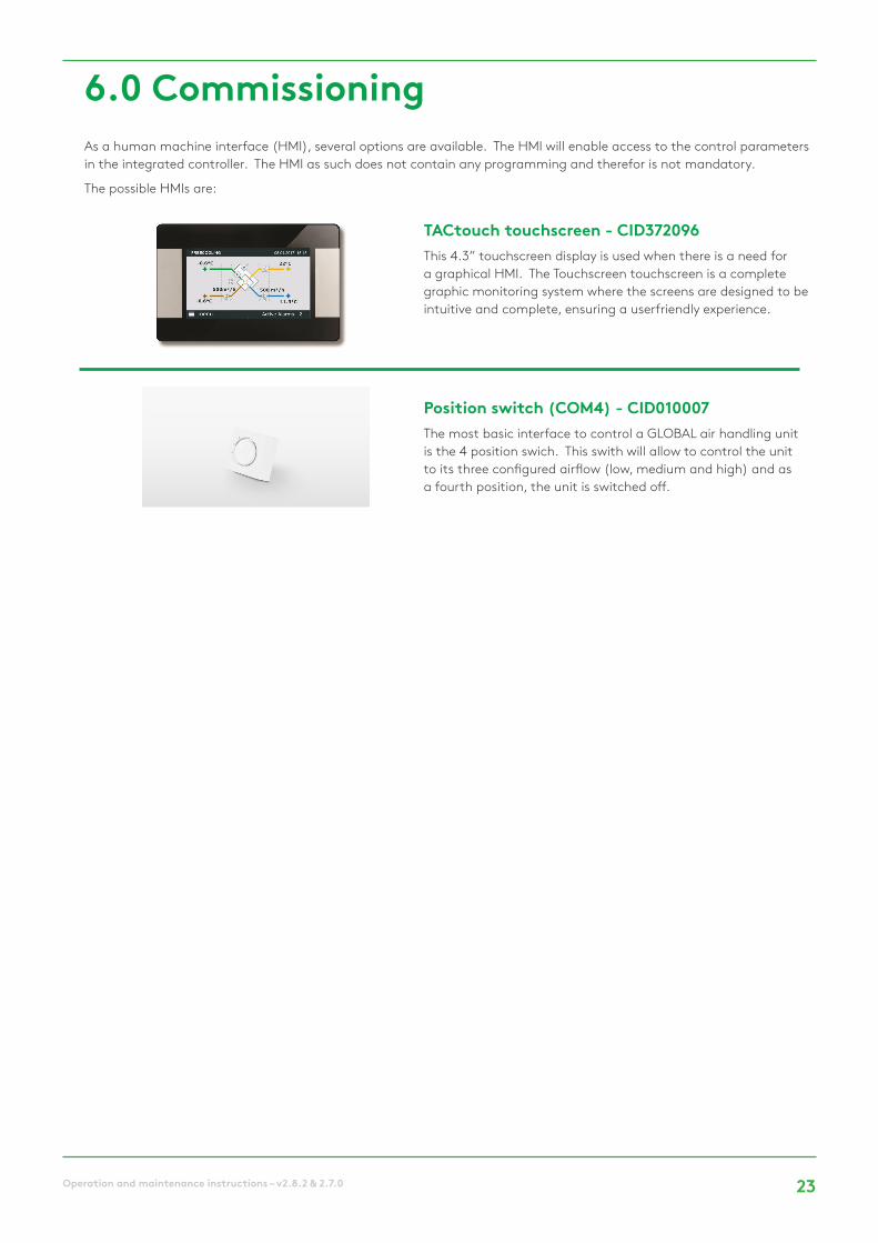
6.0 Commissioning As a human machine interface (HMI), several options are available. The HMI will enable access to the control parameters in the integrated controller. The HMI as such does not contain any programming and therefor is not mandatory.
The possible HMIs are:
TACtouch touchscreen - CID372096This 4.3” touchscreen display is used when there is a need for a graphical HMI. The Touchscreen touchscreen is a complete graphic monitoring system where the screens are designed to be intuitive and complete, ensuring a userfriendly experience.
Position switch (COM4) - CID010007The most basic interface to control a GLOBAL air handling unit is the 4 position swich. This swith will allow to control the unit to its three configured airflow (low, medium and high) and as a fourth position, the unit is switched off.

24 Operation and maintenance instructions – v2.8.2 & 2.7.0
6.1 COMMISSIONING WITH TACtouch INTERFACE
The hand-held terminal consists of a 4.3” touch screen with a 1,5 metre long cable for connection to the air handling unit's control circuit board.
If the hand-held terminal is not used for 20 minutes, it switches over to the sleep mode.
The Touchscreen controller can be used outdoors, but it must be kept at a weatherproof place.
Data:Operating temperature: 0... + 50°CMaximum length of the cable: >100 metresProtection class: IP20Dimensions [mm]: 96,8x148,8x14,5Power consumption: 120mA
IMAGE MANAGEMENT
Start-up image At the first start up, the basic setup menu will be acti-vated automatically. See section 6.1.3
Main menu. See Section 6.1.2.
The main menu is presented as a rotary menu. After pressing the “menu”-button at the bottom left corner of the Home Screen, the rotary menu will be shown.
Home Screen. See Section 6.1.1.
By default, the home screen will be shown if no other menu is opened by the user or if selected in the main menu.
N.B.! The appearance of the image varies depending on the type of air handling unit and functions selected.
LANGUAGE SELECTION
UNIT SELECTIONAIRFLOW OPERATING MODETEMPERATURE
FIRE ALARM
BASIC SETUP

25Operation and maintenance instructions – v2.8.2 & 2.7.0
6.1.1 HOME SCREENThe home screen displays the current key data for the air han-dling unit and is shown is normally displayed if no other menu has been selected or if selected from the main menu. The touch screen switches to the sleep mode after 20 minutes. To leave the sleep mode, press on the touchscreen.
On the main screen, the fields are:
• Current operation modeThe operation modes are: STOP, Heating, Cooling, Post ventilation, Freecooling, Frost protection.
• Current date and time
• Active alarmsThis fields shows the number of current alarms. By clicking on this field, more detailed information about the different alarms is available
• MenuAccessing the main menu, see section 6.1.2
• Flow ChartThe flow chart is not editable by the user, the configuration of the activated options and functions is done throught the product setup (menu). A code and a special training are desired for access to this menu. The appearence of the im-age varies depending on the type of air handling unit and its selected functions and/or options. Flow chart symbols:
Bypass (closed/open)
Water heating coil
Cooling coil
Number of current alarms
Current operation status
Main menu button
Electrical heating coil
Change over coil
Motorised damper (open/closed/opening)
Flow charts:
Plate heat exchanger Rotary heat exchanger
26 Operation and maintenance instructions – v2.8.2 & 2.7.0
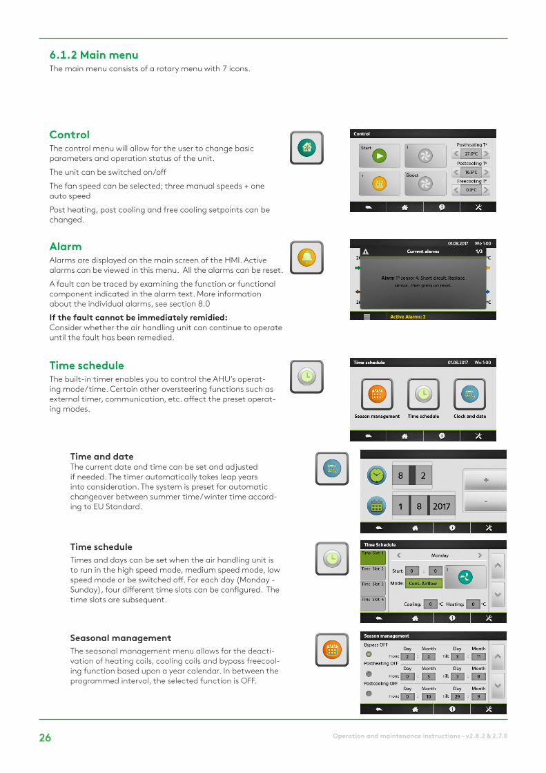
Time and dateThe current date and time can be set and adjusted if needed. The timer automatically takes leap years into consideration. The system is preset for automatic changeover between summer time/winter time accord-ing to EU Standard.
ControlThe control menu will allow for the user to change basic parameters and operation status of the unit.
The unit can be switched on/off
The fan speed can be selected; three manual speeds + one auto speed
Post heating, post cooling and free cooling setpoints can be changed.
Time scheduleThe built-in timer enables you to control the AHU’s operat-ing mode/time. Certain other oversteering functions such as external timer, communication, etc. affect the preset operat-ing modes.
AlarmAlarms are displayed on the main screen of the HMI. Active alarms can be viewed in this menu. All the alarms can be reset.
A fault can be traced by examining the function or functional component indicated in the alarm text. More information about the individual alarms, see section 8.0
If the fault cannot be immediately remidied:Consider whether the air handling unit can continue to operate until the fault has been remedied.
Time scheduleTimes and days can be set when the air handling unit is to run in the high speed mode, medium speed mode, low speed mode or be switched off. For each day (Monday - Sunday), four different time slots can be configured. The time slots are subsequent.
Seasonal managementThe seasonal management menu allows for the deacti-vation of heating coils, cooling coils and bypass freecool-ing function based upon a year calendar. In between the programmed interval, the selected function is OFF.
6.1.2 Main menuThe main menu consists of a rotary menu with 7 icons.

27Operation and maintenance instructions – v2.8.2 & 2.7.0
Basic SetupThe basic setup menu will guide the user through the most critical settings of the air handling unit. This setup procedure is described in detail, section 6.1.3
LANGUAGE SELECTION
UNIT SELECTION
AIRFLOW OPERATING MODE
TEMPERATURE
FIRE ALARM
BASIC SETUP
ReadingsThe operating status and the Settings can be read. Used for performance checks and for generally checking Set-tings, settings, power consumption, etc. No Settings can be altered in this menu group.
MaintenanceConfiguration of service related settings. A maintenance warning interval can be configured as wel as the filter clogging alarm.
Advanced setupA code and a special training are desired for access to this menu.

28 Operation and maintenance instructions – v2.8.2 & 2.7.0
BASIC SETUP
6.1.3 BASIC SETUPWhen the air handling unit is started up for the first time, the commissioning menu is automatically displayed. At the very end of the commissioning (menu) the commissioning of the unit has to be confirmed by the service technician. Once the commis-sioning has been confirmed, the commissioning menu will not be displayed as first menu any more. The commissioning menu, however, will remain accessible through the advanced setup. See Section 6.1.4.
Language selection
The language desired can be set here. The language setting can be changed at any time in the basic setup menu.
Setting Settingsrange
Factorysetting
Language Languages as displayed
English
LANGUAGE SELECTION
UNIT SELECTIONAIRFLOW OPERATING MODETEMPERATURE
FIRE ALARM
BASIC SETUP
Unit selection
The desired unit can be set here. The unit setting can be changed at any time in the basic setup menu.
Setting Settingsrange
Factorysetting
Unit m³/hl/s
m³/h
LANGUAGE SELECTION
UNIT SELECTIONAIRFLOW OPERATING MODETEMPERATURE
FIRE ALARM
BASIC SETUP
LANGUAGE SELECTION
UNIT SELECTIONAIRFLOW OPERATING MODETEMPERATURE
FIRE ALARM
BASIC SETUPAirflow operating modeThe desired operating mode can be set here. The setting can be changed at any time in the basic setup menu. Depending on the selected function, flows can be set as (l/s, m³/h), pressure (Pa), input signal strenght (%) or torque (%). For both “constant airflow” and “constant torque”, three setpoints are available: Low, medium and high.
Setting Settingsrange
Factorysetting
Operating mode OFFConstant airflowDemand controlConstant pressureConstant torque
Constant airflow

29Operation and maintenance instructions – v2.8.2 & 2.7.0
Constant airflowFlow regulation involves operating the air handling unit to keep the preset airflow constant. The speed of the fans is automatically regulated to provide correct airflow even if the filters become clogged, diffusers are blocked, etc. The exhaust air fan is controlled as a slave. A ratio between exhaust and supply pressure can be configured in order to create over, under or balanced pressure. For units with backward fans, constant airflow can only be selected if the “constant air kit” has been ordered as an option. The desired setpoint is preset in (l/s, m³/h).
Setting Range Factory set-ting
Airflow K1/K2/K3 0...max
Ratio exhaust/supply 5...999% 100%Enable pressure alarm No
YesYes
DP Supply/Exhaust for pressure alarm
25...999Pa 200Pa
Initialisation airflow (l/s, m³/h)Pressure alarm initia-lisation
NoYes
Yes
Constant torqueThe constant torque operating mode allows to vary the fan speed automatically, to provide a variable airflow for demand controlled systems. This operating mode can partially replace the constant pressure regulation when a duct pressure sensor hasn’t been installed. The exhaust air fan is controlled as a slave. A ratio between exhaust and supply pressure can be configured in order to create over, under or balanced pressure. The desired setpoint is preset in %.
Setting Range Factory settingAirflow K1/K2/K3 0...100%
Ratio exhaust/supply 5...999% 100%
Demand controlThe airflow desired is regulated in response to 0-10 V input signals from an external sensor, such as a carbon dioxide or a humidity sensor. The function can be config-ured with a positive or a negative logic. A ratio between exhaust and supply pressure can be configured in order to create over, under or balanced pressure. The desired set-point is preset in (l/s, m³/h). The “sleep factor” is a lower operating rate for the unit (due to e.g. low occupancy) that will be activated by speed “III “Setting Range Factory
settingVmin 0...10V 1,0V
Vmax 0...10V 10,0Vm³/h ~Vmin (l/s, m³/h)m³/h ~Vmax (l/s, m³/h)Ratio exhaust/supply 5...999% 100%Sleep factor on K3 10...100% 100%Enable pressure alarm No
YesYes
DP Supply/Exhaust for pressure alarm
10...999Pa 200Pa
Initialisation airflow (l/s, m³/h)Pressure alarm initia-lisation
NoYes
Yes
Constant pressureThe airflow automatically varies to provide constant pressure in the ducting. The duct pressure is measured by an external in-duct pressure sensor which is connected to the control unit’s BUS communication or the an ana-logue 0...10V input. The function can be configured on supply air, extract air or supply and extract air. The first two configurations will have the second set of fans be controlled as a slave. A ratio between exhaust and supply pressure can be configured in order to create over, under or balanced pressure. The initialisation will allow for an automatic calculated pressure setpoint, determined by the nominal airflow. The “sleep factor” is a lower operat-ing rate for the unit (due to e.g. low occupancy) that will be activated by speed “III “
Setting Range Factory setting
Control SupplyExhaustSupply+Exhaust
Supply
Ratio exhaust/supply 5...999% 100%Sleep factor on K3 10...100% 100%Pressure initialisation Via Airflow
Via PressureAirflow
Start reference initia-lisation
YesNo
Yes

30 Operation and maintenance instructions – v2.8.2 & 2.7.0
TemperatureThe temperature regulation can be configured as a supply air regulation or an extract air regulation. By default, this function is configured as a supply air temperature control. Changes to this configuration are done in the advanced setup; see Section 6.1.4
Setting Settingsrange
Factorysetting
T° heating 0...45°C 20,0°CT° Cooling 0...99°C 24,0°CT° Freecooling 0...99°C 15°C
Fire AlarmAn external fire detection system is used to control the air handling unit in case of emergency. The fire alarm function is activated by means of digital input IN3.
Setting Settingsrange
Factorysetting
Input Normally openNormally closed
Normally closed
Supply airflow 0...maxExtract airflow 0...max
Periodic maintenance
Built-in timer for maintenance warning; if the maintenance interval is exceeded, a maintenance reminder will be displayed.
Setting Settingsrange
Factorysetting
3 monthly warning YesNo
No
12 monthly warning YesNo
No
Commissioning completed
When the commissioning has been successfull and this is confirmed in this menu, the commissionig menu will not be activated automatically anymore.
Setting Settingsrange
Factorysetting
Confirmation of successfull commis-sioning
YesNo
No
LANGUAGE SELECTION
UNIT SELECTIONAIRFLOW OPERATING MODETEMPERATURE
FIRE ALARM
BASIC SETUP
LANGUAGE SELECTION
UNIT SELECTIONAIRFLOW OPERATING MODETEMPERATURE
FIRE ALARM
BASIC SETUP
UNIT SELECTIONAIRFLOW OPERATING MODETEMPERATURE
FIRE ALARM
BASIC SETUP
AIRFLOW OPERATING MODETEMPERATURE
FIRE ALARM
BASIC SETUP
PERIODIC MAINTENANCE
PERIODIC MAINTENANCECOMMISSIONING COMPLETED

31Operation and maintenance instructions – v2.8.2 & 2.7.0
6.1.4 ADVANCED SETUPN.B.! The appearance and content of this menu varies depending on the type of air handling unit and functions and/or options selected. A code and a special training are desired for access to this menu group.
Attention: The settings range for most of the functions is defined for maximal flexibility. The factory setting is the advised setting, deviating from this setting requires carefull consideration.
Stop fan with 0...10VFunction only availalbe if “demand control” function has been selected in basic setup. With this function, the fans can be stopped if the 0...10V control signal is below or above a specified setpoint. The control signal is connected to the analogue input K2.
Setting Settingsrange
Factorysetting
Stop if <Vlow NoYes
Yes
Vlow 0...10V 0,8VStop if >Vhigh No
YesYes
Vhigh 0...10V 10,0V
Second 0...10V control signalFunction only availalbe if “demand control” function has been selected in basic setup. With this function, a separate 0...10V control signal for the extract air can be activated. The control signal is connected to the ana-logue input K3.
Setting Settingsrange
Factorysetting
0...10V on K3? NoYes
No
Control Exhaust Supply
Exhaust
Constant pressureFunction only availalbe if “constant pressure” function has been selected in basic setup. The reaction speed of the fans for the balancing of the constant pressure system can be modified. A higher Setting will result in a faster reaction speed; a lower Setting will result in a slowerreaction speed. The system can be defined as a negative or a positive logic. A negative logic airflow drops when analogue signal on K2 is > than the setpoint.
Setting Settingsrange
Factorysetting
Reaction speed 0...10 10Logic Positive
NegativeNegative
ADVANCED SETUP
STOP FAN WITH 0...10V
2ND 0...10 CONTROL SIGNALCONSTANT PRESSURESOFT STOP
START TORQUE
ADVANCED SETUP
STOP FAN WITH 0...10V
2ND 0...10 CONTROL SIGNALCONSTANT PRESSURESOFT STOP
START TORQUE
ADVANCED SETUP
STOP FAN WITH 0...10V
2ND 0...10 CONTROL SIGNALCONSTANT PRESSURESOFT STOP
START TORQUE
ADVANCED SETUP

32 Operation and maintenance instructions – v2.8.2 & 2.7.0
Stop fan when pressure alarmPossibility to stop the fans automatically in case of a pressure alarm.
Setting Settingsrange
Factorysetting
Stop fans NoYes
No
Start torque
Possibility to change the fans’s starting torque.
Setting Settingsrange
Factorysetting
Start Torque 0...100% 2%
Deactivate softstopWith this function, the “OFF”key on any HMI is deactivated.
Setting Settingsrange
Factorysetting
Softstop YesNo
No
Temperature regulationIn this menu advanced temperature control parameters can be modified.
Supply air regulation involves keeping a constant supply air temperature without consideration to the load in the premises.
Extract air regulation involves keeping a constant tempera-ture in the extract air duct (premises), by regulating the supply air temperature.
The reaction speed of capacity control signal can be modified. A higher Setting will result in a smoother control; a lower Set-ting will result in a faster reaction speed. but also greater risc of oscillations.
Setting Settingsrange
Factorysetting
Supply or Extract tempe-rature control?
SupplyExtract
Supply
Reaction speed 1...10 1Supply air, min 0...20°C 15,0°CSupply air, max 16...50°C 28,0°CStop fan if T°Supply <5°C No
YesNo
2ND 0...10 CONTROL SIGNAL
CONSTANT PRESSURESTOP FANSTART TORQUE
DEACTIVATE SOFTSTOP
BASIC SETUP
CONSTANT PRESSURE
STOP FANSTART TORQUEDEACTIVATE SOFTSTOP
TEMPERTURE REGULATION
BASIC SETUP
CONSTANT PRESSURE
DEACTIVATE SOFTSTOPTEMPERATURE REGULATIONBOOST
POST VENTILATION
BASIC SETUP

33Operation and maintenance instructions – v2.8.2 & 2.7.0
BoostThe boost mode can be used to force the supply and extract airflow to a higher setpoint, when specific conditions are met. The boost mode can be activated with a contact connected to the digital input IN9 or by an analogue 0...10V control signal connected to input K3. The boost setpoint is preset in (l/s, m³/h).
Setting Settingsrange
Factorysetting
Supply / Extract airflow 0...maxBoost activation on Contact
RHContact
RH on / off 0...100% 60% / 40%Vmin/max RH on K3 0...10V 2,0V / 9,5VRH ~Vmin/max 0...100% 2% / 95%
Post ventilationThe post ventilation function is used to keep the fans running during a specified laps of time. This function is activated auto-matically when an electrical heating coil is activated.
Setting Settingsrange
Factorysetting
Activation NoYes
No
Time 0...9999sec 90sec
DEACTIVATE SOFTSTOP
TEMPERATURE REGULATIONBOOSTPOST VENTILATION
EXTERNAL COILS
BASIC SETUP
TEMPERATURE REGULATION
BOOSTPOST VENTILATIONINTERNAL COILS
EXTERNAL COILS
BASIC SETUP

34 Operation and maintenance instructions – v2.8.2 & 2.7.0
Internal coils
Water preheating coilBy preheating the outdoor air, it is possible to prevent mois-ture precipitation in the AHU’s outdoor air filter, to reduce the risk of frosting in the heat exchanger and to eliminate the risk that pressure sensors and motor control systems are operating in too low ambient temperature. The setpoint is of the exhaust air temperature.
Setting Settingsrange
Factorysetting
Setpoint -9,9...99,9°C 1,0°C
Electrical preheating coilBy preheating the outdoor air, it is possible to preventmoisture precipitation in the outdoor air fi lter of the airhandling unit, to reduce the risk of frosting in the heatexchanger and to eliminate the risk that the ambient tem-perature will drop lower than minimum permissible. The electrical preheating coil is installed and configured in fac-tory. The electrical preheating coil will always have its sepa-rate power supply and main switch.
Setting Settingsrange
Factorysetting
Setpoint -9,9...99,9°C 1,0°CPID - Proportional Band 0...100 5PID - Integral 0...100 30PID - Derivate 0...100 11
Electrical postheating coilThe electrical postheating coil is installed and configured in factory. The electrical postheating coil will always have its separate power supply and main switch. The capacity of the coil will be controlled proportionally in order to keep a tem-perature as defined by the selected operating mode.
Setting Settingsrange
Factorysetting
Control mode ExhaustSupply
Supply
Setpoint -9,9...99,9°C 21,0°CPID - Proportional Band 0...100 5PID - Integral 0...100 30PID - Derivate 0...100 11
Water postheating coilThe water postheating coil is installed and configured in factory. The 3-way valve is not installed and will have to be installed and wired on site. The capacity of the coil will be controlled proportionally in order to keep a temperature as defined by the selected operating mode. The output O.R.3 on the optional “SAT3” output relay, is activated whenever heating is desired.
Setting Settingsrange
Factorysetting
Control mode ExhaustSupply
Supply
Setpoint -9,9...99,9°C 21,0°CReaction Speed 1...10 5
BOOST
POST VENTILATIONINTERNAL COILSEXTERNAL COILS
INTERNAL COILS
BASIC SETUP

35Operation and maintenance instructions – v2.8.2 & 2.7.0
External coilsConfiguration of the coils
This menu will allow for the configuration of any combi-nation of external heating and or cooling coil(s).
Setting Settingsrange
Factorysetting
Type NoneHeating waterCooling waterCooling & heating waterCombi coil waterElectrical PWMElectrical PWM + coolingWater preheatingWater preheating+postheating Water preheating+change overElectrical 0...10V Electrical 0...10V + cooling
None
Water post heatingThe external post heating coil is delivered seperately from the air handling unit and will not be pre configured in factory. Both the coil and the 3-way valve will have to be installed and wired on site. The capacity of the coil will be controlled proportionally in order to keep a temperature as defined by the selected operating mode. The reaction speed can be set. A higher Setting will result in a faster reaction speed; a lower Setting will result in a slower reac-tion speed.
Setting Settingsrange
Factorysetting
Control mode ExhaustSupply
Supply
Setpoint 0...99,9°C 21,0°CReaction Speed 1...10 5
Water cooling coilThe external post cooling coil is delivered seperately from the air handling unit and will not be pre configured in factory. Both the coil and the 3-way valve will have to be installed and wired on site. The capacity of the coil will be controlled proportionally in order to keep a temperature as defined by the selected operating mode.
Setting Settingsrange
Factorysetting
Control mode ExhaustSupply
Supply
Setpoint 0...99°C 17,0°CReaction Speed 1...10 5
Electrical postheating coilThe external post heating coil is delivered seperately from the air handling unit and will not be pre configured in fac-tory. The coil will have to be installed and wired on site. The capacity of the coil will be controlled proportionally in order to keep a temperature as defined by the selected operating mode.
Setting Settingsrange
Factorysetting
Control mode ExhaustSupply
Supply
Setpoint 0...+99°C 21,0°C
PID - Proportional Band 0...100 5PID - Integral 0...100 30PID - derivate 0...100 11
Combi coilThe external change over coil is delivered seperately from the air handling unit and will not be pre configured in fac-tory. The coil will have to be installed and wired on site. The capacity of the coil will be controlled proportionally in order to keep a temperature as defined by the selected operating mode.
Setting Settingsrange
Factorysetting
Activate change over NoYes
No
Neutral band High 0...+50°C 4KNeutral band Low 0...+50°C 2K
BOOST
POST VENTILATIONEXTERNAL COILSFROST PROTECTION
FREECOOLING
BASIC SETUP

36 Operation and maintenance instructions – v2.8.2 & 2.7.0
Frost protection heating and cooling coilsThe water coils are always protected against freezing by an anti-frost temperature sensor. This sensor is monted on the surface of the water coil. When the anti-frost protection temperature of the hydraulic coil detects a tempeature lower than 4°C (default), the pump contact is closed and the 3 way valve is opened 100% during 15 minutes. If the unit is running, the alarm is activated immediately. For a water preheating coil, the frost alarm is delayed by 2 minutes. If frost protection conditions occur when the air handling unit is OFF, the alarm is delayed by 5 minutes.
Setting Settingsrange
Factorysetting
Internal heating coil -10...+10°C +4,0°CExternal heating coil -10...+10°C +4,0°CExternal cooling coil -10...+10°C +4,0°CInternal preheating coil -10...+10°C +4,0°C
Freecooling (PX units)The modulating bypass on the GLOBAL PX product range, can be configured for freecooling. The main parameters to activate the free cooling function are the outside temperature (T1) and the extract (room) air temperature (T2). When there is maximal freecooling possibility the bypass will be 100% open. The 100% opened bypass can activate the configurable freecooling airflow.
Setting Settingsrange
Factorysetting
Outdoor T° 0...27°C 0,0°CExtract/Room T° 6...28°C 22,0°CSupply airflow (l/s, m³/h)Extract airflow (l/s, m³/h)Bypass control Frost protection
FreecoolingFrost protection & free cooling
Freecooling
Frost protection
Frost protection plate heat exchangers (PX)In environments where the extract air can occasionally be humid, the defrosting function can be activated to protect the heat exchanger from frosting. There are four strategies: down regulation of the supply air volume, modulating by-pass control, modulation of capacity of a pre-heating coil, differential pressure measurement (cold climate option). If non of these measures are effective, the air handling unit can be stopped by limting the mini-mal supply air temperature. When the Frost protection cycle is active, it will be indicated on the HMI. The config-urable temperatures are outdoor temperatures.
Setting Settingsrange
Factorysetting
T° Low 1...3°C +1,0°CT° High 1...5°C +5,0°CStop supply airflow No
YesYes
Frost protection rotary heat exchangers (RX)In environments where the extract air can occasion-ally be humid, the defrosting function can be activated to protect the heat exchanger from frosting. The speed of the rotating heat exchanger is linked to the tem-perature of the supply (sensor T1). When the Frost pro-tection cycle is active, it will be indicated on the HMI.
Setting Settingsrange
Factorysetting
Activate Frost protection -10...+99°C -9°CRX rotation speed 2...10RPM 2RPM
Frost protection cycle active
Frost protection alarm
Frost protection NominalRotation speed

37Operation and maintenance instructions – v2.8.2 & 2.7.0
Modbus configuration
The MODBUS RTU communication requires an additional satellite circuit (CID050043) which is used as commu-nication interface. The communication protocol used is MODBUS RTU, RS485.
Setting Settingsrange
Factorysetting
Adress 1...247 1Baudrate 1200
4800960019200
9600
Parity NoYes
No
LAN configurationThe MODBUS TCP/IP communication requires an addi-tional satellite circuit (CID 025072) which is used as com-munication interface. The communication protocol used is Modbus TCP/IP on Ethernet network over twisted pair 10 BASE T/100Base-TX IEEE 802.3.Setting Settings
rangeFactorysetting
IP configuration DHCPManual
Manual
IP adress 192.168.1.1Netmask 255.255.255.0Gatway 0.0.0.0
Operating timeFor maintenance purposes, operating timers can be acti-vated. If the “service alarm time” or the “Stop fan” timers are triggered, the according alarm will be shown and the unit will switch to “OFF”-mode.
Setting Settingsrange
Factorysetting
Reset timer NoYes
No
Fan run time activation NoYes
No
Display time NoYes
No
Service alarm time 0...999999h 0hStop fan 0...999999h 0h
Analogue outputThe controller has as a standard feature two configur-able analogue 0...10V outputs. The outputs represent the actual airflow (or torque) or the actual pressure delivered by one of the selected fans.
Setting Settingsrange
Factorysetting
Output 1 Flow Fan 1Pressure Fan 1Flow Fan 2Pressure Fan 2Flow Fan 3Pressure Fan 3Flow Fan 4Pressure Fan 4Torque Fan 1Torque Fan 2Torque Fan 3Torque Fan 4
Flow Fan 1
Output 2 Flow Fan 1Pressure Fan 1Flow Fan 2Pressure Fan 2Flow Fan 3Pressure Fan 3Flow Fan 4Pressure Fan 4Torque Fan 1Torque Fan 2Torque Fan 3Torque Fan 4
Pressure Fan 1

38 Operation and maintenance instructions – v2.8.2 & 2.7.0
Attention : before handling and/or opening the access panels it is compulsory to shut down the unit and disconnect the power supply using the general switch located on the front panel. Do not isolate the power supply whilst the unit is running. If KWin and\or KWout are installed, then isolate the corresponding power supplies.
Regular maintenance is essential to guarantee good operation of the air handling unit and a long service life. The maintenance frequency will depend on the application and on the actual environment conditions but the following are general guidelines:
Replace the filters with a kit of replacement filters.
- Check for any alarms indicated on the control device. In case of an alarm refer to troubleshooting section.
- Check the state of filter clogging. The control device allows a pre-defined ‘filter alarm’ threshold to be set. Replace filters if necessary. Filters that are too clogged can generate the following problems:
- Insufficient ventilation
- Excessive increase of fan rotation speed
- Excessive sound levels
- Excessive power consumption (power consumption will increase exponentially to an increase in pressure drop, for a constant airflow)
- Unfiltered air passing through the heat exchanger (risk of clogging) and into ventilated rooms.
The list of replacement filter kits for each unit can be downloaded from our website.
- Inspection and cleaning of the inside of the unit:
• Vacuum clean any accumulations of dust in the unit.
• Inspect and gently vacuum clean the heat exchanger if necessary. Use a brush to protect the fins.
• Clean any condensation stains
• For PX units, clean any accumulations in the drainage pan.
7.1 ONCE THE UNIT OPERATES IN NORMAL CONDITION
7.2 EVERY 3 MONTHS
7.0 Preventive maintenance

39Operation and maintenance instructions – v2.8.2 & 2.7.0
1. For rotary heat exchanger (RX) units, check the brush seals on the rotary heat exchanger along the perimeter in contact with the frame:
If necessary, bring the brush seals closer to the exchanger to ensure good sealing.
2. For RX units, check the tension of the driving belt on the rotating heat exchanger. If there is no tension or if the belt is damaged, please, contact the service department for a belt replacement.
Ideally the heat exchanger should be cleaned using vacuum cleaner with a soft nozzle to prevent damaging the air passages in the rotor. Turn the rotor by hand to enable you to vacuum clean its entire surface. If the heat exchanger is substantially fouled, it can be blown clean with compressed air.
3. For plate heat exchanger (PX) units:
• Clean the drainage pan
• Clean the inside of the bypass. To access the interior of the bypass it is necessary to force it open, proceed as follows: place a jumper between terminals IN4 and +12V on the TAC5 circuit board. The bypass is now open, irrespective of the temperature conditions.
• Remember to remove the jumper between terminals IN4 and +12V once cleaning of bypass is done.
• Always clean against the regular direction of airflow.
• Cleaning must only be done by blowing with compressed air, vacuum cleaning with a soft nozzle or through wet cleaning with water and/or solvent. Before you begin cleaning, cover adjacent functional sections to protect them. If cleaning solvent is used, do not use solvent that will corrode aluminium or copper.
4. Fan maintenance:
Check again whether the power supply is shut down and fans are not running.
Inspect and clean the fan impellers to remove any dirt deposits, be careful not to alter the impeller balance (do not remove balancing clips). Check the impeller to make sure that it is not out of balance. Clean or brush off the fan motor. It can also be cleaned by carefully wiping it with a damp cloth that has been dipped in a solution of water and detergent. Clean the fan space, if needed. Remove the fans if necessary.
5. Check seals on the unit:
Ensure that the side access panels are fully closed and that the seals are intact. Replace if necessary.
7.3 EVERY 12 MONTHS

40 Operation and maintenance instructions – v2.8.2 & 2.7.0
8.0 Troubleshooting
- Conditions:
- Causes:
• Failure of fan Fx. This problem is usually caused by the fan motor. If not, the failure may be caused by an internal cable (control or power) or by the TAC5 circuit.
- Effects:
The TAC5 control board generates and reports 18 types of alarms.
The alarms are subdivided into auto resetting and non-auto resetting alarms. For the latter, a reset will be necessary once the problem has been resolved.
For each type of alarm, a full text description will be displayed on the user interface depending on the alarm type:
- Activation of contact relay (NC or NO contact)- AL 1
- Activation of SAT3 OR1 in case of pressure alarm, provided that the optional module SAT 3 is installed on the control board.
- “Alarm”, “Pa” and “AF” activated LED’s on control board
- Alarm on user interface.
- Alarm communication with networking modules provided that an optional communication module (Modbus RTU, MODBUS TCP/IP, and KNX) is installed on the TAC5 control board.
8.1 TYPE 1: ALARM INDICATING A FAN FAILURE
Action on user interface
Text displayed LED ALARM LED Pa
ALARM FANx Red /
Action on user interface
AL1 relay O.R.1 relay of SAT3 LED ALARM LED AF Fans
Alarm / ON / stopped
Auto reset: yes

41Operation and maintenance instructions – v2.8.2 & 2.7.0
- Conditions:
• Mode CA or LS. Unit must have forward fans or backward fans with kit CA.
• External pressostat connected on IN2 input
- Causes:
• Pressure alarm setup in CA or LS mode
• External pressostat connected on IN2 input has triggered
- Effects:
* unless the status has been changed in advanced setup
8.2 TYPE 2: ALARM ON THE PRESSURE VARIATION
Action on user interface
Text displayed LED ALARM LED Pa
PRESSURE ALARM / Red
Actions on TAC5 circuit and fans
AL1 relayO.R.1 relay
of SAT3LED ALARM LED AF Fans
/ Closed ON / Run*
Auto reset: yes
42 Operation and maintenance instructions – v2.8.2 & 2.7.0
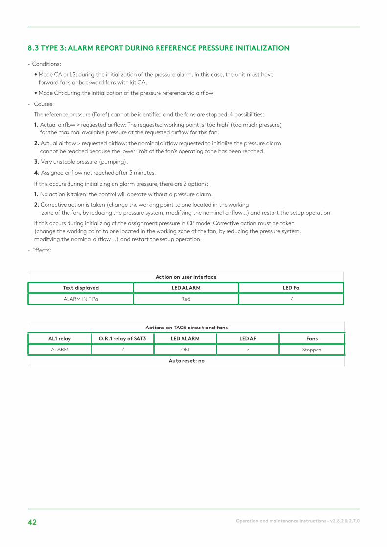
- Conditions:
• Mode CA or LS: during the initialization of the pressure alarm. In this case, the unit must have forward fans or backward fans with kit CA.
• Mode CP: during the initialization of the pressure reference via airflow
- Causes:
The reference pressure (Paref) cannot be identified and the fans are stopped. 4 possibilities:
1. Actual airflow < requested airflow: The requested working point is ‘too high’ (too much pressure) for the maximal available pressure at the requested airflow for this fan.
2. Actual airflow > requested airflow: the nominal airflow requested to initialize the pressure alarm cannot be reached because the lower limit of the fan’s operating zone has been reached.
3. Very unstable pressure (pumping).
4. Assigned airflow not reached after 3 minutes.
If this occurs during initializing an alarm pressure, there are 2 options:
1. No action is taken: the control will operate without a pressure alarm.
2. Corrective action is taken (change the working point to one located in the working zone of the fan, by reducing the pressure system, modifying the nominal airflow…) and restart the setup operation.
If this occurs during initializing of the assignment pressure in CP mode: Corrective action must be taken (change the working point to one located in the working zone of the fan, by reducing the pressure system, modifying the nominal airflow …) and restart the setup operation.
- Effects:
8.3 TYPE 3: ALARM REPORT DURING REFERENCE PRESSURE INITIALIZATION
Action on user interface
Text displayed LED ALARM LED Pa
ALARM INIT Pa Red /
Actions on TAC5 circuit and fans
AL1 relay O.R.1 relay of SAT3 LED ALARM LED AF Fans
ALARM / ON / Stopped
Auto reset: no

43Operation and maintenance instructions – v2.8.2 & 2.7.0
- Conditions:
- Causes:
• The setpoint cannot be fulfilled because the upper or lower limit of the fan’s working zone has been reached
- Effects:
* unless the status has been changed in advanced setup
- Conditions:
- Causes:
• Crucial data from the circuit board has been lost
- Effects:
- Solutions:
• Try a TOTAL RESET of the data using the advanced setup. If still not resolved, order a new circuit board.
8.4 TYPE 4: ALARM INDICATING THE SYSTEM CANNOT FULFIL THE SETPOINT
8.5 TYPE 5: ALARM INDICATING A DATA FAILURE IN THE CONTROL CIRCUIT
Action on user interface
Text displayed LED ALARM LED Pa
ALARM CA/LS/CP / /
Action on user interface
Text displayed LED ALARM LED Pa
DATA ERROR Red /
Actions on TAC5 circuit and fans
AL1 relay O.R.1 relay of SAT3 LED ALARM LED AF Fans
/ / ON / /
Auto reset: yes
Actions on TAC5 circuit and fans
AL1 relay O.R.1 relay of SAT3 LED ALARM LED AF Fans
Alarm status / ON / Stopped
Auto reset: no

44 Operation and maintenance instructions – v2.8.2 & 2.7.0
- Conditions:
• Fire alarm input must be connected to a fire detection system
- Causes:
• Activation of fire alarm input, IN3, connected to a fire detection system. IN3 can be configured to work as NO open contact by default or as NC if configured so in the advanced setup.
- Effects:
* Special management: the fans are stopped by default in the event of a fire alarm but, via the advanced setup, it is possible to configure a fixed airflow for supply (contact IN7 needs to be closed) and for exhaust (contact IN8 needs to be closed).
8.6 TYPE 6: FIRE ALARM
Action on user interface
Text displayed LED ALARM LED Pa
FIRE ALARM Red /
Actions on TAC5 circuit and fans
AL1 relay O.R.1 relay of SAT3 LED ALARM LED AF Fans
Alarm status / ON / *
Auto reset: no

45Operation and maintenance instructions – v2.8.2 & 2.7.0
- Conditions:
• the running hours feature must be enabled in advanced setup
- Causes:
• SERVICE ALARM: the fan operating time (in hours) has exceeded the configurable threshold
• STOP FAN: the fan operating time (in hours) has exceeded the configurable threshold. This alarm stops the fans
- Effects:
* unless the status has been changed in advanced setup
- Conditions:
• User interface is RC TAC5
- Causes:
• Communications failure between the TAC5 circuit and the RC TAC5
- Effects:
8.7 TYPE 7: MAINTENANCE ALARM
8.8 TYPE 8: ALARM INDICATING A COMMUNICATION BREAKDOWN BETWEEN THE TAC5 CIRCUIT AND THE RC TAC5 CIRCUIT
Action on user interface
Text displayed LED ALARM LED Pa
SERVICE ALARM / SERVICE STOP FAN Red /
Action on user interface
Text displayed LED ALARM LED Pa
CB COM ERROR Red /
Actions on TAC5 circuit and fans
AL1 relayO.R.1 relay of
SAT3LED ALARM LED AF Fans
Alarm status / ON / Stopped if SERVICE STOP FAN
Reset via “fan run time” (RC) or “alarm menu” (GRC and App)
Actions on TAC5 circuit and fans
AL1 relayO.R.1 relay of
SAT3LED ALARM LED AF Fans
Alarm status / / / /
Auto reset: yes
46 Operation and maintenance instructions – v2.8.2 & 2.7.0
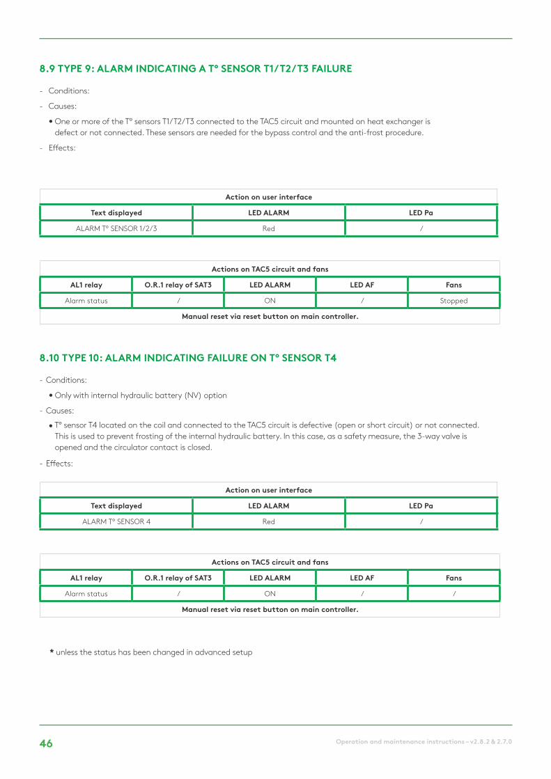
- Conditions:
- Causes:
• One or more of the T° sensors T1/T2/T3 connected to the TAC5 circuit and mounted on heat exchanger is defect or not connected. These sensors are needed for the bypass control and the anti-frost procedure.
- Effects:
- Conditions:
• Only with internal hydraulic battery (NV) option
- Causes:
• T° sensor T4 located on the coil and connected to the TAC5 circuit is defective (open or short circuit) or not connected. This is used to prevent frosting of the internal hydraulic battery. In this case, as a safety measure, the 3-way valve is opened and the circulator contact is closed.
- Effects:
* unless the status has been changed in advanced setup
8.9 TYPE 9: ALARM INDICATING A T° SENSOR T1/T2/T3 FAILURE
8.10 TYPE 10: ALARM INDICATING FAILURE ON T° SENSOR T4
Action on user interface
Text displayed LED ALARM LED Pa
ALARM T° SENSOR 1/2/3 Red /
Action on user interface
Text displayed LED ALARM LED Pa
ALARM T° SENSOR 4 Red /
Actions on TAC5 circuit and fans
AL1 relay O.R.1 relay of SAT3 LED ALARM LED AF Fans
Alarm status / ON / Stopped
Manual reset via reset button on main controller.
Actions on TAC5 circuit and fans
AL1 relay O.R.1 relay of SAT3 LED ALARM LED AF Fans
Alarm status / ON / /
Manual reset via reset button on main controller.
47Operation and maintenance instructions – v2.8.2 & 2.7.0
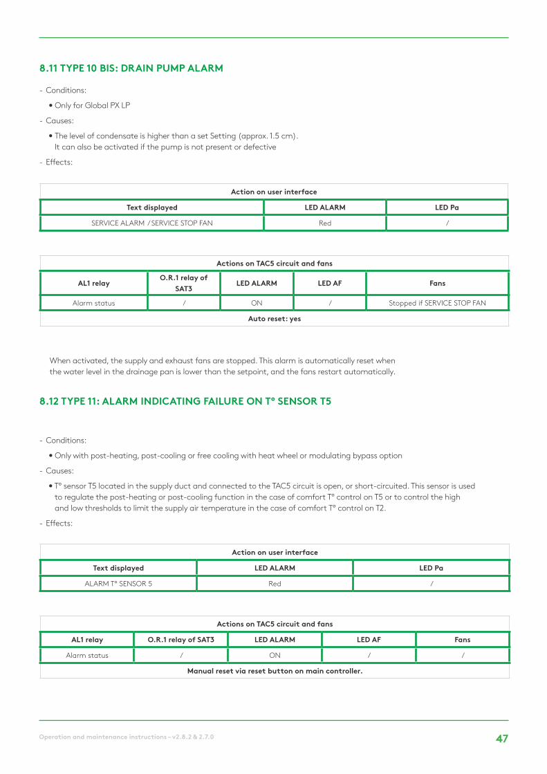
- Conditions:
• Only for Global PX LP
- Causes:
• The level of condensate is higher than a set Setting (approx. 1.5 cm). It can also be activated if the pump is not present or defective
- Effects:
When activated, the supply and exhaust fans are stopped. This alarm is automatically reset when the water level in the drainage pan is lower than the setpoint, and the fans restart automatically.
- Conditions:
• Only with post-heating, post-cooling or free cooling with heat wheel or modulating bypass option
- Causes:
• T° sensor T5 located in the supply duct and connected to the TAC5 circuit is open, or short-circuited. This sensor is used to regulate the post-heating or post-cooling function in the case of comfort T° control on T5 or to control the high and low thresholds to limit the supply air temperature in the case of comfort T° control on T2.
- Effects:
8.11 TYPE 10 BIS: DRAIN PUMP ALARM
8.12 TYPE 11: ALARM INDICATING FAILURE ON T° SENSOR T5
Action on user interface
Text displayed LED ALARM LED Pa
SERVICE ALARM / SERVICE STOP FAN Red /
Action on user interface
Text displayed LED ALARM LED Pa
ALARM T° SENSOR 5 Red /
Actions on TAC5 circuit and fans
AL1 relayO.R.1 relay of
SAT3LED ALARM LED AF Fans
Alarm status / ON / Stopped if SERVICE STOP FAN
Auto reset: yes
Actions on TAC5 circuit and fans
AL1 relay O.R.1 relay of SAT3 LED ALARM LED AF Fans
Alarm status / ON / /
Manual reset via reset button on main controller.

48 Operation and maintenance instructions – v2.8.2 & 2.7.0
- Conditions:
• Only with post-heating option
- Causes:
• The comfort T° setpoint cannot be reached (actual T° lower than setpoint during 15 minutes, or 30 minutes if comfort on T2 instead of T5, while post heating is at maximum.
- Effects:
8.13 TYPE 12: ALARM INDICATING THAT THE COMFORT T° IS TOO LOW RELATIVE TO SETPOINT T°
Action on user interface
Text displayed LED ALARM LED Pa
ALARM POSTHEAT T° TOO LOW Red /
Actions on TAC5 circuit and fans
AL1 relay O.R.1 relay of SAT3 LED ALARM LED AF Fans
/ / ON / /
Auto reset: yes

49Operation and maintenance instructions – v2.8.2 & 2.7.0
- Conditions:
• Only with post-heating option
- Causes:
• For PX units:
Frost protection is only selected with KWin or BAin or modulating bypass. With KWin or BAin option: In certain air T° conditions as measured on the exhaust airflow after heat recovery, indicating that the internal electrical KWin coil or external hydraulic coil (BAin) has reached its limit, the TAC5 control can take over to guarantee the anti-frost function.
If T° < assignment T°-1,5°C for more than 5 minutes: supply and exhaust airflow reduction of 33% if CA or LS and of 25% if CP, for 15 minutes.
• For RX units:
When external temperature (T1 sensor) is lower than the anti-frost temperature (T°AF, -9°C by default), the rotation speed of the heat exchanger will decrease to avoid any risk of frosting.
After that T1 ≥ T°AF during 5 minutes, then the wheel will turn back at nominal rotation speed
- Effects:
8.14 TYPE 13: ALARM INDICATING HEAT EXCHANGER FROST PROTECTION ALERT
Action on user interface
Text displayed LED ALARM LED Pa
AF T° ALARM AIRFLOW REDUCED Red /
Actions on TAC5 circuit and fans
AL1 relay O.R.1 relay of SAT3 LED ALARM LED AF Fans
/ / ON ON /
Auto reset: yes

50 Operation and maintenance instructions – v2.8.2 & 2.7.0
- Conditions:
• Frost protection is only selected for PX units with KWin or BAin or if modulating bypass
- Causes:
• With KWin or BAin option: in certain air T° conditions as measured on the exhaust airflow after the heat recovery, indicating that the internal electrical KWin coil or external hydraulic coil (BAin) has reached its limit, the TAC5 control can take over to guarantee the anti-frost function.
If T° < -5°C during 5 minutes, fans are stopped.
• With modulating bypass in frost protection (« A-FREEZE » or « AF+FREECOOL » in the advanced setup), this alarm indicates that the extracted air temperature at the exchanger output (T3 sensor) has not exceeded 1°C during 15 minutes after that the bypass has been opened at 100%.
- Effects:
8.15 TYPE 14: ALARM INDICATING FROST PROTECTION ALERT – FANS STOPPED T°
Action on user interface
Text displayed LED ALARM LED Pa
AF T° ALARM STOP FANS Red /
Actions on TAC5 circuit and fans
AL1 relay O.R.1 relay of SAT3 LED ALARM LED AF Fans
Alarm status / ON Blinking Stopped
Manual reset via reset button on main controller.

51Operation and maintenance instructions – v2.8.2 & 2.7.0
- Conditions:
• Only for RX units
- Causes:
• This alarm indicates that the rotation speed of the wheel has been lower or greater than 15% of the setpoint speed for more than 5 minutes
- Effects:
- Conditions:
• Only with post cooling option
- Causes:
• The comfort T° setpoint cannot be reached (actual T° lower than setpoint during 15 minutes, or 30 minutes if comfort on T2 instead of T5, while post cooling is at maximum).
- Effects:
8.16 TYPE 14 BIS: ALARM INDICATING AN ERROR ON THE HEAT EXCHANGER ROTATION SPEED
8.17 TYPE 15 BIS: ALARM INDICATING THAT THE COMFORT T° IS TOO HIGH RELATIVE TO SETPOINT T°
Action on user interface
Text displayed LED ALARM LED Pa
WHEEL ALARM Red /
Action on user interface
Text displayed LED ALARM LED Pa
ALARM POSTCOOL T° TOO HIGH Red /
Actions on TAC5 circuit and fans
AL1 relay O.R.1 relay of SAT3 LED ALARM LED AF Fans
Alarm status / ON / Stopped
Manual reset via reset button on main controller.
Actions on TAC5 circuit and fans
AL1 relay O.R.1 relay of SAT3 LED ALARM LED AF Fans
/ / ON / /
Auto reset: yes

52 Operation and maintenance instructions – v2.8.2 & 2.7.0
- Conditions:
• Only with post heating or cooling option
- Causes:
• This alarm indicates that the supply temperature (T5) is lower than 5°C. The fans are stopped for 1 minute. The alarm is configurable through the advanced setup and is disabled by default.
- Effects:
- Conditions:
• Only with hydraulic post heating inside the unit, NV, or outside the unit, BA
- Causes:
• Indicates that the anti-frost protection temperature of the hydraulic coil is lower than 4°C (configurable through advanced setup, it is important to reduce this Setting for BAin coil if an antifreeze is in the fluid). The 3-way valve is automatically ordered to be opened at 100% for 15 minutes and the pump contact is ordered closed (contact SAT3 O.R.3 if internal NV or WP-WP contact on SAT BA/KW if external BA coil). If the fans turn, the alarm is sent after 2 minutes for BAin coil and immediately for the others; if the fans are stopped, the alarm is sent after 5 minutes.
- Effects:
7.18 TYPE 16: ALARM INDICATING THAT THE SUPPLY T° IS TOO LOW
8.19 TYPE 17: ALARM INDICATING HYDRAULIC COILS FROST PROTECTION ALERT
Action on user interface
Text displayed LED ALARM LED Pa
AF NV/BA STOP FANS Red /
Action on user interface
Text displayed LED ALARM LED Pa
AF NV/BA STOP FANS Red /
Actions on TAC5 circuit and fans
AL1 relay O.R.1 relay of SAT3 LED ALARM LED AF Fans
Alarm Status / ON / Stopped
Manual reset via reset button on main controller.
Actions on TAC5 circuit and fans
AL1 relay O.R.1 relay of SAT3 LED ALARM LED AF Fans
Alarm Status / ON / Stopped
Manual reset via reset button on main controller.

53Operation and maintenance instructions – v2.8.2 & 2.7.0
- Conditions:
• PX units with modulating bypass
- Causes:
• This alarm indicates that the modulating bypass has not reached the ordered position within 10 seconds. The most common reason for this is a damaged position sensor on the bypass actuator, and this must be replaced. Other reasons may be that the control board output is damaged, implying the replacement of the board, or a mechanical blocking verified by a visual inspection of the bypass
- Effects:
- Conditions:
• The basic setup parameter “Filters Resets” must be higher than 0
- Causes:
• Alarm indicating that the hours limit for the maintenance of the filters has been reached
- Effects:
8.20 TYPE 18: ALARM INDICATING AN INCORRECT POSITION OF THE MODULATING BYPASS RELATIVE TO THE ORDERED POSITION
8.21 TYPE 19: ALARM INDICATING THAT THE HOURS LIMIT FOR THE MAINTENANCE OF THE FILTERS HAS BEEN REACHED
Action on user interface
Text displayed LED ALARM LED Pa
BYPASS % STOP FANS Red /
Displayed on RC/GRC
Text displayed LED ALARM LED Pa
FILTERS ALARM Red /
Actions on TAC5 circuit and fans
AL1 relay O.R.1 relay of SAT3 LED ALARM LED AF Fans
Alarm Status / ON / Stopped
Manual reset via reset button on main controller.
Status Circuit board & fans
AL1 relay O.R.1 relay of SAT3 LED ALARM LED AF Fans
/ / ON / /
Auto reset: via dedicated reset

54 Operation and maintenance instructions – v2.8.2 & 2.7.0
- Conditions:
• Unit with counter flow heat exchanger
- Causes:
• The ice forming inside of the plate heat exchanger is genrating a pressure drop that is to high for the current airflow. This detection requires a Modbus pressure sensor placed on the heat exchanger and that the modulation of the fans speed is based on the airflow and not on torque
• When the previous detection is not available, the supply T° is checked and if it falls below 11°C, it is considered that is due to the ice that reduces the heat exchanger efficiency
- Effects:
8.22 TYPE 20: ALARM INDICATING THAT THE DEFROST PROCESS IS ACTIVE
Displayed on RC/GRC
Text displayed LED ALARM LED Pa
DEFROST ALARM Red /
Status Circuit board & fans
AL1 relay O.R.1 relay of SAT3 LED ALARM LED AF Fans
/ / ON ON Supply stopped
Auto reset: yes
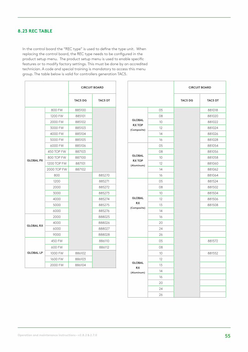
55Operation and maintenance instructions – v2.8.2 & 2.7.0
8.23 REC TABLE
In the control board the “REC type” is used to define the type unit. When replacing the control board, the REC type needs to be configured in the product setup menu. The product setup menu is used to enable specific features or to modify factory settings. This must be done by an accredited technician. A code and special training is mandatory to access this menu group. The table below is valid for controllers generation TAC5.
CIRCUIT BOARD CIRCUIT BOARD
TAC5 DG TAC5 DT TAC5 DG TAC5 DT
GLOBAL PX
800 FW 885100
GLOBALRX TOP
(Composite)
05 881018
1200 FW 885101 08 881020
2000 FW 885102 10 881022
3000 FW 885103 12 881024
4000 FW 885104 14 881026
5000 FW 885105 16 881028
6000 FW 885106
GLOBALRX TOP
(Aluminum)
05 881054
450 TOP FW 887103 08 881056
800 TOP FW 887100 10 881058
1200 TOP FW 887101 12 881060
2000 TOP FW 887102 14 881062
800 885270 16 881064
1200 885271
GLOBALRX
(Composite)
05 881524
2000 885272 08 881502
3000 885273 10 881504
4000 885274 12 881506
5000 885275 13 881508
6000 885276 14
GLOBAL RX
2000 888025 16
4000 888026 20
6000 888027 24
9000 888028 26
GLOBAL LP
450 FW 886110
GLOBALRX
(Aluminum)
05 881572
600 FW 886112 08
1000 FW 886102 10 881552
1600 FW 886103 12
2000 FW 886104 13
14
16
20
24
26

56 Operation and maintenance instructions – v2.8.2 & 2.7.0
9.0 Parameters/Commissioning Sheet Please enter all settings specific to your installation in this table. Please keep this document at hand when there is a need to contact us to report a problem.
9.1 MAIN PARAMETERS AFTER COMMISSIONING
1 GLOBAL model:
2 Operating mode: O Constant Airflow (CA)
O Demand control (LS)
O Constant Torque (TQ)
O Constant pressure (CP)
3 Constant Airflow:
K1 = O [m³/h] O [l/s]
K2 = O [m³/h] O [l/s]
K3 = O [m³/h] O [l/s]
4 Constant Torque:
K1 = % Torque
K2 = % Torque
K3 = % Torque
5 Demand control:
Vmin = V
Vmax = V
m³h / %TQ Vmin = O [m³/h] O [l/s]
m³h / %TQ Vmax = O [m³/h] O [l/s]
% on K3 = %
6 Constant pressure:Assignment Pa = O [V] O [Pa]
% on K3 = %
7 Ratio exhaust / supply: %
8Pressure alarm
(CA / LS only)
Activated?O Yes O No
O Automatic O Manual
Setup Initialisation:
Supply: O [m³/h] O [l/s] O [Pa]
Exhaust: O [m³/h] O [l/s] O [Pa]
9 If KWin option: T° KWin = °C
10 If KWout option T° KWout = °C
11 If NV option: T° NV = °C
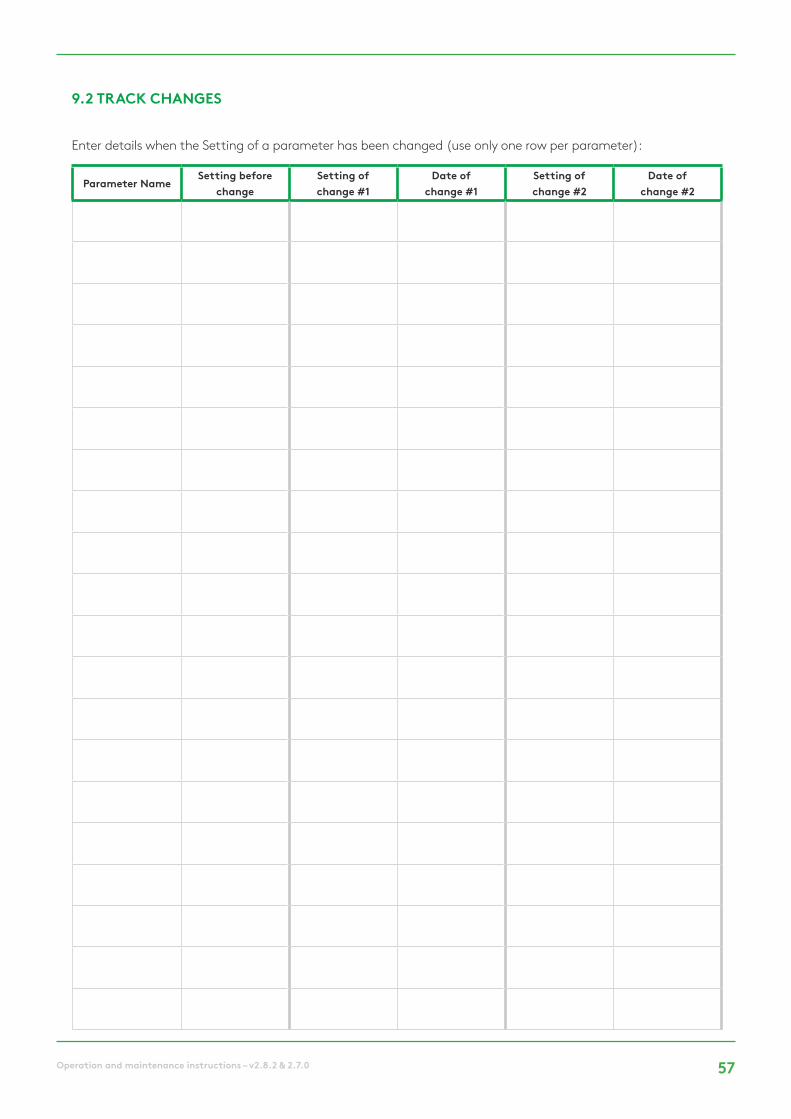
57Operation and maintenance instructions – v2.8.2 & 2.7.0
Enter details when the Setting of a parameter has been changed (use only one row per parameter):
9.2 TRACK CHANGES
Parameter NameSetting before
changeSetting of change #1
Date of change #1
Setting of change #2
Date of change #2


We make every breath count.
Version: 21/03/2018
We reserve the right for changes.