Global Navigation Satellite System Module · The Global Navigation Satellite System (GNSS) Module...
57
GNSS Module Manual © 2020, Systemyde International Corporation 1 Global Navigation Satellite System Module
Transcript of Global Navigation Satellite System Module · The Global Navigation Satellite System (GNSS) Module...

GNSS Module Manual
© 2020, Systemyde International Corporation 1
Global Navigation SatelliteSystem Module

GNSS Module Manual
© 2020, Systemyde International Corporation 2
Every effort has been made to ensure the accuracy of the information contained herein. If you find errors orinconsistencies please bring them to our attention.
Copyright © 2019-2020, Systemyde International Corporation. All rights reserved.
Notice:
“HP-41C”, “HP-41CV”, “HP-41CX” and “HP” are registered trademarks of Hewlett-Packard, Inc. All usesof these terms in this document are to be construed as adjectives, whether or not the noun “calculator”, “CPU” or “device” are actually present.
Acknowledgements:
Mark Fleming provided the initial impetus for this 41C module and software, and provided guidance duringthe development. Nate Martin provided the design of the module housing. Sylvain Côté, Mark Fleming,Ángel Martin and Robert Prosperi reviewed the preliminary specification.

GNSS Module Manual
© 2020, Systemyde International Corporation 3
Disclaimer
The GNSS Module should not be used in such a manner that deficiencies, omissions, inaccuracies or errorscould result in death, loss or injury.
WARRANTIES AND DISCLAIMER
The GNSS Software is supplied “as is” and without any warranty of any kind, either express, implied, or arising by statute, custom, course of dealing, or trade usage. Systemyde International Corporationspecifically disclaims any and all implied warranties or conditions of title, non-infringement, accuracy orcompleteness, the presence or absence of errors, fitness for a particular purpose, merchantability, orotherwise. Some jurisdictions do not allow the exclusion of implied warranties, so this exclusion may notapply to you.
LIMITATION OF LIABILITY
Subject to any liability that may not be excluded or limited by law, Systemyde International Corporation isnot liable for, and expressly excludes, all liability for loss or damage however and whenever caused toanyone by any use of the GNSS Module, whether by you or by anyone else, and whether caused by anyfault on the part of Systemyde International Corporation or not. This exclusion of liability includes, but isnot limited to, any special, incidental, consequential, punitive, or exemplary damages such as loss ofrevenue, data, anticipated profits, and lost business. This exclusion applies even if Systemyde InternationalCorporation has been advised of the possibility of such damages.
If liability may not be excluded by law, it is limited to actual and direct financial loss to the extent it iscaused by proved negligence on the part of Systemyde International Corporation.
It is particularly important to realize that the GNSS position information may not be accurate. You shouldmake your own judgement about the accuracy of the GNSS position information. This is especially true forflying, inland navigation, marine navigation, and military applications. You are strongly advised not to usethe GNSS Module as your primary or sole information source for these activities.

GNSS Module Manual
© 2020, Systemyde International Corporation 4
Table of Contents
1. Introduction .......................................................................................................... 7
2. Batteries and Current Drain .............................................................................. 9
3. GNSS Data Formats ............................................................................................. 11
4. Receiver Control Functions ................................................................................ 14
GNAUTO (GNSS Receiver Automatic On-Off) ...........................................14GNON (GNSS Receiver On) .........................................................................14GNAON (GNSS Receiver Always On) ......................................................... 15GNSBY (GNSS Receiver in Standby) .......................................................... 15GNOFF (GNSS Module Off) ........................................................................15GNACT? (GNSS Receiver Active?) .............................................................15GNTRK? (GNSS Receiver Tracking?) ......................................................... 16
5. Individual GNSS Data Functions .......................................................................17
DATUM (Generate GNSS Datum) .................................................................17LAT (Retrieve Latitude) .................................................................................18LON (Retrieve Longitude) ............................................................................. 19ALTI (Retrieve MSL Altitude) .......................................................................19HEADING (Retrieve Heading) ......................................................................20SPEED (Retrieve Speed) .............................................................................. 20UTIME (Retrieve UTC Time) ........................................................................21UDATE (Retrieve UTC Date) ........................................................................21SATS (Retrieve GNSS Satellites Used) ......................................................... 21SATIV (Retrieve GNSS Satellites In View) ................................................... 22GEOID (Retrieve Geoidal Separation) .......................................................... 22HDOP (Retrieve Horizontal Dilution of Precision) .......................................22VDOP (Retrieve Vertical Dilution of Precision) ........................................... 23
6. Waypoint Functions ............................................................................................ 24
AC (Altitude and Course) .............................................................................. 25ACT (Altitude, Course and Time) ..................................................................25ACTD (Altitude, Course, Time and Date) ..................................................... 26CT (Course and Time) ................................................................................... 26CTD (Course, Time and Date) ....................................................................... 26LL (Position) .................................................................................................. 26LLA (Position and Altitude) ...........................................................................27LLAC (Position, Altitude and Course) .......................................................... 27LLACT (Position, Altitude, Course and Time) ..............................................27LLACTD (Position, Altitude, Course, Time and Date).................................. 27
GNSS Module Manual
© 2020, Systemyde International Corporation 5
LLC (Position and Time) ............................................................................... 28LLCT (Position, Course and Time) ............................................................... 28LLCTD (Position, Course, Time and Date).................................................... 28LLT (Position and Time) ................................................................................28LLTD (Position, Time and Date).................................................................... 29
7. Waypoint Housekeeping Functions ................................................................... 30
GPTRP (Use Waypoint Pointer Register) .....................................................30GPTRX (Use X-Register as waypoint pointer) ............................................. 30RCLWBR (Recall Waypoint Base Register) .................................................31STOWBR (Store Waypoint Base Register) .................................................. 31RCLWPR (Recall Waypoint Pointer Register) .............................................31STOWPR (Store Waypoint Pointer Register) ...............................................31WPR+X (Add X to Current Waypoint Register) ...........................................32RCLRNG (Recall Waypoint Register Range) ...............................................32
8. Miscellaneous Functions ..................................................................................... 33
DMT (Convert to Degrees-Minutes-Tenths) ..................................................33GMODE (Set GNSS Mode) .......................................................................... 33GMODE* (Set Default GNSS Mode) ............................................................35GMODE? (Query GNSS Modes) ..................................................................35GCLOCK (Continuously Display UTC Time) ..............................................36
9. ROM Option Functions ...................................................................................... 37
DISROM (Disable GNSS Module ROM) ..................................................... 37ENROM (Enable GNSS Module ROM) ........................................................37RELROM (Relocate GNSS Module ROM) .................................................. 37WRROM (Enable Writeable GNSS Module ROM) ......................................37
10. Direct Communication Functions ...................................................................... 38
GPEEK (Read GNSS Control Register) ....................................................... 38GPOKE (Write GNSS Control Register) ......................................................38GRDA (Read GNSS Inbound Buffer as Alpha) ............................................ 38GRDH (Read GNSS Inbound Buffer as Hex) ............................................... 39GWRA (Write GNSS Outbound Buffer as Alpha) ........................................39GWRH (Write GNSS Outbound Buffer as Hex) ...........................................39
11. Error Conditions .................................................................................................. 40
12. Internal Details ..................................................................................................... 42
String Buffer Control .......................................................................................46String Buffer Data ........................................................................................... 47String Buffer Claim ......................................................................................... 47String Buffer Release ...................................................................................... 47GNSS Control/Status .......................................................................................48
GNSS Module Manual
© 2020, Systemyde International Corporation 6
ROM Control ...................................................................................................51Scratch 1 ..........................................................................................................52Scratch 2 ..........................................................................................................52Inbound Buffer Control/Status ........................................................................ 53Inbound Buffer Data ........................................................................................54Outbound Buffer Control/Status ..................................................................... 55Outbound Buffer Data ..................................................................................... 56
13. Revision History ....................................................................................................57
GNSS Module Manual
© 2020, Systemyde International Corporation 7
IntroductionThe Global Navigation Satellite System (GNSS) Module adds functionality previouslyunavailable in a 41C system, and is compatible with the 41C, 41CV, 41CX and 41CL.This module provides position information, including latitude, longitude and altitude,course information, including speed and heading, as well as accurate time and dateinformation.
The GNSS Module is housed in a 3-D printed double-length module housing that can beplugged into any Port of the calculator. When plugged into Port 3, the module allows theCard Reader to still be used with the calculator.
Like the Card Reader and Time Module, the GNSS Module uses a fixed pageaddress, independent of its physical location in the calculator. Where the CardReader uses page 14 and the Time Module uses page 5, the GNSS Module uses page15 by default.
If the page 15 address is inconvenient the ROM in the GNSS Module can be relocated toany available page under software control. In addition, the ROM can be disabled and thesoftware run from an external source, such as a QRAM device (MLDL2K, Clonix, NoV-64K, etc), or an internal image in the 41CL.
The ROM in the GNSS Module is implemented using a RAM that is loaded with theGNSS Software when the module is first plugged in. Normally this RAM is read-only,but writes can be enabled via a function in the GNSS Software. This allows the softwareto be patched or even completely replaced. However, any patching or replacement is onlyactive as long as the GNSS Module is powered.
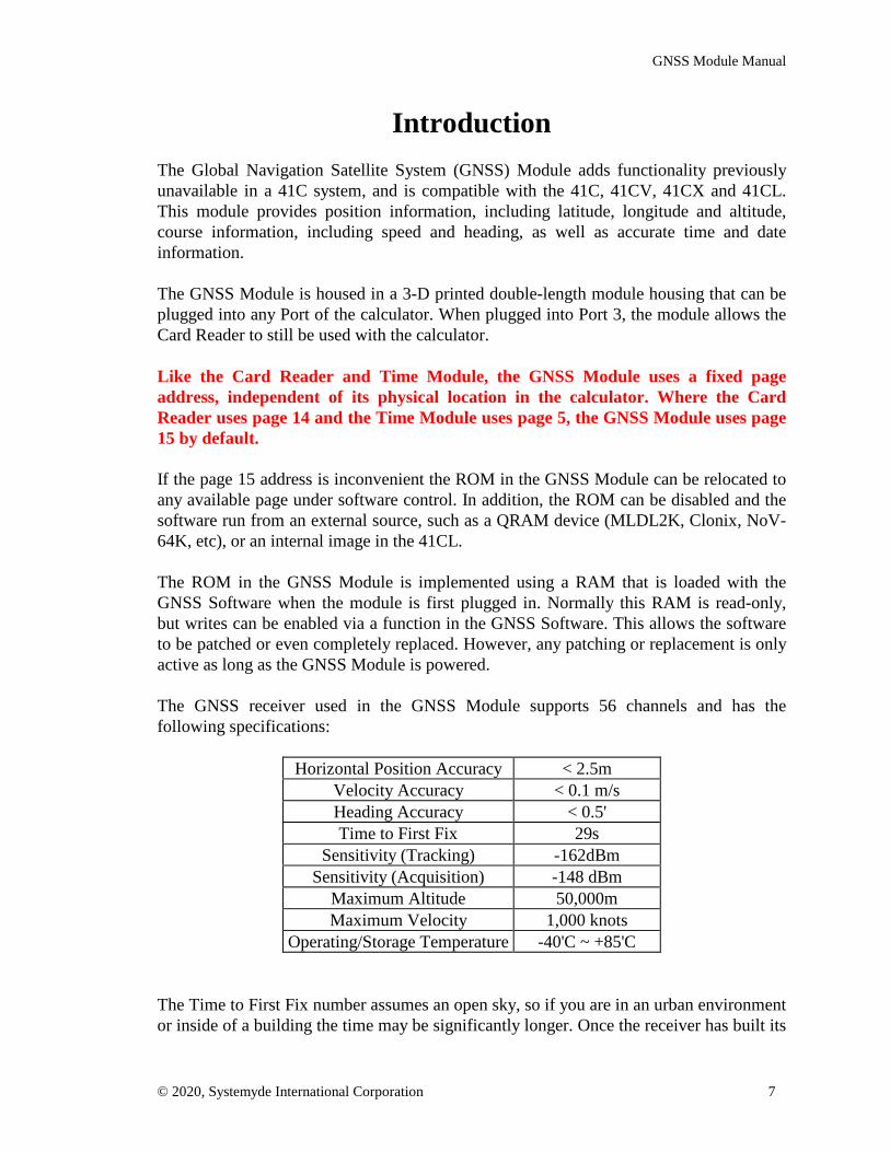
The GNSS receiver used in the GNSS Module supports 56 channels and has thefollowing specifications:
Horizontal Position Accuracy < 2.5mVelocity Accuracy < 0.1 m/sHeading Accuracy < 0.5'Time to First Fix 29s
Sensitivity (Tracking) -162dBmSensitivity (Acquisition) -148 dBm
Maximum Altitude 50,000mMaximum Velocity 1,000 knots
Operating/Storage Temperature -40'C ~ +85'C
The Time to First Fix number assumes an open sky, so if you are in an urban environmentor inside of a building the time may be significantly longer. Once the receiver has built its

GNSS Module Manual
© 2020, Systemyde International Corporation 8
almanac (containing the approximate orbital data for all satellites) the time required for afix is usually significantly reduced.
The GNSS Software provides keyboard or program access to individual GNSS data aswell as the means to store waypoints in 41C registers. The GNSS Software in the GNSSModule is grouped into seven categories:
1. The Receiver Control functions allow you to turn the GNSS receiver on or off andverify the current status of the GNSS receiver.
2. The Individual GNSS Data functions read the selected value from the latest position fixand write this information to the stack.
3. The Waypoint functions are a convenient way to store GNSS data directly to 41Cregisters. A waypoint requires a minimum of two and a maximum of eight registers.
4. The Waypoint Housekeeping functions allow you to control where the GNSSwaypoints are stored in the 41C register memory, and provide a way to communicate thisinformation to other programs that might use the waypoint data.
5. The Miscellaneous functions select the display format for some of the IndividualGNSS Data functions and provide format conversions.
6. The ROM Option functions provide control over the ROM in the GNSS Module.
7. The Direct Communication functions allow direct access to the serial port thatcommunicates with the GNSS receiver.

GNSS Module Manual
© 2020, Systemyde International Corporation 9
Batteries and Current DrainWhile the GNSS Reciever is active, it requires about the same amount of current as aWand during a barcode scan or a Card Reader during a card read or write. The tablebelow shows the details.
GNSS receiver state ModuleCurrent drain
Standby 750 μAActive (Acquisition) 47 mA
Active (Tracking) 37 mA
While a fresh set of batteries should last for several hours, it is best not to leave the GNSSReceiver active for any longer than necessary. The GNSS software provides a number ofpower-control options for the GNSS receiver that will be detailed below.
The GNSS Receiver is in the Standby state when the module is first inserted into thecalculator, and also when the calculator is off unless overridden by user command.
The GNSS Receiver enters the Active (Acquiring) state when first turned on. Typicallythe receiver will require about 30 seconds to acquire sufficient GNSS information toallow the automatic transition to the Active (Tracking) state.
In the Active (Tracking) state the GNSS Receiver updates the position information in thebuffers internal to the GNSS Module once every second. This information can then beaccessed at any time using functions in the GNSS software. Functions are providied toquery the state of the GNSS receiver.
The GNSS Receiver supports other power-saving modes, which can further reduce thepower requirements, but this requires special control messages to initiate. Refer to theUblox documentation (UBX-13003704) for the details about this type of operation. Thesespecial messages can be issued using the the GWRA and GWRH functions.
To support the different use cases the GNSS software provides five different functions tocontrol the power for the GNSS receiver.
Function Operation Low Batt NormalExecute Calc Off
GNAUTO Automatic Standby & beep On StandbyGNON On Standby & beep On On
GNAON Always On On On OnGNSBY Standby Standby Standby StandbyGNOFF Off Off Off Off
GNSS Module Manual
© 2020, Systemyde International Corporation 10
The Automatic mode is enabled by the GNAUTO function. In this mode the GNSSreceiver is active until the calculator is turned off, at which point the GNSS receiver isautomatically placed in Standby. Note that because of the way that automatic shut-downfeature of the 41C calculator is designed, there is no way to notify a peripheral like theGNSS Module that an automatic shut-down has occurred. This means that in this case theGNSS receiver will remain powered after the shut-down.
The GNAUTO function turns the GNSS receiver on unless the BAT annunciator isalready on. This function checks the battery status before, but not after, the GNSSreceiver is turned on. This means that if the batteries are weak the GNSS receiver willstill be turned on but the BAT annunciator may be activated at the same time. Then thenext time the battery condition is tested (which normally happens after every keypress)the GNSS receiver will enter the Standby state and the calculator will beep to signal tothe user that this state change has occurred.
The On mode is enabled by the GNON function. The mode is identical to the Automaticmode except that the GNSS receiver will remain on even when the calculator is turnedoff.
The Always On mode is enabled by the GNAON function. In this mode the GNSSreceiver remains on even if a low-battery condition is detected.
The Standby mode is enabled by the GNSBY function. This is the default mode, selectedwhen the GNSS Module is first inserted in the calculator and after a MEMORY LOSTcondition. In this mode the GNSS receiver is in Standy by mode but the remainder of theGNSS Module remains active.
The Off mode is enabled by the GNOFF function. In this mode the GNSS receiver is inStandy by mode and the remainder of the GNSS Module is disabled. In this mode theGNSS Module will still respond to reads and writes but no direct communication with theGNSS receiver is possible.

GNSS Module Manual
© 2020, Systemyde International Corporation 11
GNSS Data FormatsThe GNSS Receiver in the GNSS Module outputs position information as serial strings ofASCII characters according to the NMEA-0183 (National Maritime ElectronicsAssociation) standard. Circuitry in the GNSS Module converts these serial strings intobytes and buffers the bytes prior to making them available to the Individual GNSS Datafunctions and Waypoint functions.
The NMEA protocol defines specific formats for the various data that make up a GNSSposition according to the table below:
GNSS dataNative Data
FormatUnits Range
Latitude ddmm.mmmmmdd: degrees
mm.mmmmm: minutes-90≤ degrees ≤ +90
00.00000≤minutes≤59.99999
North/South characterN: North Latitude,S: South Latitude
Longitude dddmm.mmmmmddd: degrees
mm.mmmmm: minutes-180≤ degrees ≤ +180
00.00000≤minutes≤59.99999
East/West characterE: East Longitude,W: West Longitude
Altitude decimal number meters < 50,000 m
Heading decimal number degrees0≤ degrees < 360
clockwise from due NorthSpeed decimal number knots 0≤ knots< 1,000
UTC hhmmss.sshh: hours
mm: minutesss.ss: seconds
00≤ hours ≤ 2300≤ minutes ≤ 59
00.00≤ seconds ≤ 59.99
UTC Date ddmmyydd: day
mm: monthyy:year
01≤ day ≤ 3101≤ month ≤ 1200≤ year ≤ 99
Satellites used integer 0≤ satellites used ≤ 12Satellites in View integer 0≤ satellites in view ≤ 32
Geoidal Separation decimal number meters refer to WGS-84 for detailsHDOP decimal number see belowVDOP decimal number see below
While the GNSS Receiver is starting up not all GNSS position information becomes validat the same time. For example, time and date require a signal from only one satellite.Horizontal position requires information from three satellites, while altitude requires foursatellites. Even then, depending on the relative location of the satellites, the positioninformation may be inaccurate. The table below shows progression of valid positioninformation.

GNSS Module Manual
© 2020, Systemyde International Corporation 12
Satellites used Fix type Valid position precision measurement0 Invalid none
1-2 1D time, date only3 2D latitude, longitude HDOP≥ 4 3D latitude, longitude, altitude HDOP, VDOP
The HDOP (Horizontal Dilution of Precision) and VDOP (Vertical Dilution of Precision)numbers are measures of the precision of the position information:
DOP precision≤ 1 ideal
1 - 2 excellent2 - 5 good
5 - 10 moderate10 - 20 fair≥ 20 poor
HDOP and VDOP can be combined to provide an overall Position Dilution of Precision(PDOP) using the formula:
PDOP = (HDOP2 + VDOP2)1/2
To mitigate potential problems with other programs interpreting GNSS data, beforestoring the data the GNSS Software always reformats the latitude, longitude, heading,UTC Time and UTC Date into a format that makes it easy to use with existing 41Csoftware.
The latitude, longitude and heading are stored as signed decimal degrees in the standard41C floating point number format. Following accepted convention, North latitude ispositive and South latitude is negative. Similarly, East longitude is positive and Westlongitude is negative.
The signed decimal degrees latitude, longitude and heading values that are stored can beconverted to degrees-minutes-tenths (dd.mmmmmm) using the DMT function or todegrees-minutes-seconds (dd.mmssss) using the regular 41C HMS function.
The UTC Time and UTC Date values are reformated into the same formats used by theTime Module for time and date. UTC Time is always reported in 24 hour format, andUTC Date is always reported in the DMY format.

GNSS Module Manual
© 2020, Systemyde International Corporation 13
The table below shows the formats used for the stored GNSS data, including waypoints.
GNSS data Stored Data Format Stored Units Stored Data RangeLatitude standard 41C number degrees -90≤ degrees ≤ +90
Longitude standard 41C number degrees -180≤ degrees ≤ +180Altitude standard 41C number meters < 50,000 mHeading standard 41C number degrees 0≤ degrees < 360Speed standard 41C number knots 0≤ speed < 1,000
UTC HH.MMSShh
HH: hoursMM: minutesSS: seconds
hh:hundredths of seconds
00≤ hours ≤ 2300≤ minutes ≤ 5900≤ seconds ≤ 59
00≤ hundredths≤ 99
UTC Date dd.mmyyyydd: day
mm: monthyyyy:year
01≤ day ≤ 3101≤ month ≤ 12
year≤ 2099
With the exception of UTC Time and UTC Date, all values are stored as standard 41Cfloating point numbers that contain a 10-digit mantissa and a 2-digit exponent. However,the precision of individual GNSS data values is determined by the GNSS Receiver, whichis based on a u-blox 7 receiver. Refer to the u-box 7 receiver specification for detailsabout the precision of individual GNSS data values.
There is a boundary condition for longitude values (±180 degrees) that is not defined inthe GNSS Receiver specification. If you ever cross the International Date Line with yourGNSS Module active, please let us know how this boundary condition is handled!

GNSS Module Manual
© 2020, Systemyde International Corporation 14
Receiver Control FunctionsThe GNSS Receiver Control functions allow you to turn the GNSS receiver on or off andverify the current status of the GNSS receiver.
GNAUTO
Executing GNAUTO (GNSS Receiver Automatic Mode) places the GNSS Receiver inActive mode. In this mode the receiver will attempt to track satellites and update theposition information.
In the Active mode the current drain on the calculator batteries is significant, but a freshset of alkaline batteries should last for several hours of continuous use. This functionchecks the battery condition before turning on the GNSS receiver, and if a low batterycondition is present, the function will merely beep and exit, without turning on the GNSSreceiver. If the GNSS receiver was already on when this function is executed and a lowbattery condition is detected the function will beep and the GNSS receiver will be placedin Standby mode to reduce current drain.
After entering Active mode, the GNSS Receiver typically requires about 30 seconds toacquire the satellite signals and update the position information. During this time invalidposition information is reported using the Alpha string INV.
In this mode the GNSS receiver is active until the calculator is turned off, at which pointthe GNSS receiver is automatically placed in Standby. Note that because of the way thatautomatic shut-down feature of the 41C calculator is designed, there is no way to notify aperipheral like the GNSS Module that an automatic shut-down has occurred. This meansthat in this case the GNSS receiver will remain powered after the shut-down.
GNON
Executing GNON (GNSS Receiver On) places the GNSS Receiver in Active mode. Thismode is identical to the Automatic mode selected by the GNAUTO function, except thatthe GNSS receiver will not automatically be placed in Standby mode when the calculatoris turned off.

GNSS Module Manual
© 2020, Systemyde International Corporation 15
GNAON
Executing GNAON (GNSS Receiver Always On) places the GNSS Receiver in Activemode, independent of the state of the battery. In this mode the GNSS receiver alsoremains in Active mode when the calculator is turned off.
GNSBY
Executing GNSBY (GNSS Receiver in Standby) places the GNSS Receiver in Standbymode. In this mode the current drain on the calculator batteries is significantly reduced,because the receiver is neither tracking satellites nor updating the position information.
The GNSS receiver is automatically placed in Standby mode when the module is firstinserted into the calculator and by a MEMORY LOST condition. While the GNSSreceiver is in Standby mode all position information is reported using the Alpha stringINV.
This command does not turn off the other logic in the GNSS Module.
GNOFF
Executing GNOFF (GNSS Receiver Off) places the GNSS Receiver in Standby mode, aswell as disabling some of the logic in the GNSS Module itself. In this mode the GNSSModule will still respond to reads and writes but no direct communication with the GNSSreceiver is possible because the oscillator that clocks the serial communication with theGNSS receiver is disabled.
GNACT?
Executing GNACT? (Test GNSS Receiver Active Status) tests the power state of theGNSS receiver, returning with NO in the display if the GNSS Receiver is in Standbymode and YES in the display when the GNSS Receiver is in Active mode. When used ina program, if the GNSS receiver is in Active mode the next program line will beexecuted; if the GNSS Receiver is in Standby mode the next line in the program isskipped.

GNSS Module Manual
© 2020, Systemyde International Corporation 16
GNTRK?
Executing GNTRK? (Test GNSS Receiver Tracking Status) tests the tracking state of theGNSS Receiver, returning with NO in the display if the GNSS Receiver is in Standbymode or not yet tracking and YES in the display when the GNSS Receiver is in Activemode and tracking. When used in a program, if the GNSS Receiver is tracking the nextprogram line will be executed; if the GNSS Receiver is in Standby mode or not yettracking the next line in the program is skipped.
The table below shows the various combinations for these two GNSS Receiver tests.
GNSS receiver state GNACT? GNTRK?Standby NO NO
Active (Acquisition) YES NOActive (Tracking) YES YES
The state of the GNSS Receiver is reported based on the status in the "Mode 2" field ofthe GPGSA NMEA string. Hardware in the GNSS Module automatically extracts theinformation in this field from the output of the GNSS Receiver.

GNSS Module Manual
© 2020, Systemyde International Corporation 17
Individual GNSS Data FunctionsThe Individual GNSS Data functions retrieve and display individual components of aGNSS position fix. The data displayed is not read directly from the GNSS output buffers,but must first be transferred to the Datum Buffer internal to the GNSS Module. This isbecause individual components of the GNSS position can change between successivefunction calls.
The Datum Buffer is only updated by command and retains its contents for as long as theGNSS Module is powered. The Datum Buffer consists of normal 41C registers that existoutside of the normal 41C register address space. Like all other 41C registers, theregisters in the Datum Buffer can hold a floating point number or a short Alpha string.Valid entries are always floating point numbers and invalid entries are marked with theAlpha string INV.
All of the data retrieval functions return the data to the X-register, even if the data is theAlpha string INV. In addition, the primary data retrieval functions (for latitude, longitude,altitude, heading, speed, time and date) also return the data to the Alpha register and thedisplay, although this feature can be disabled for latitude, longitude, altitude, heading andspeed.
This ALPHA/display feature allows information about the units to be appended to thedata. This appended units feature is enabled by default, but can be disabled using theGMODE function with the NOA (No Alpha) mode identifier. The format of the datareturned to the ALPHA register and the display is contolled by the current display mode(FIX, SCI or ENG.)
Writing data to the display does not occur in program mode, even if enabled, because inprogram mode the display is updated by the operating system to show program execution.
DATUM
Executing DATUM (Generate GNSS Datum) reads the latest position output from theGNSS Receiver, extracts all of the relevant information, and transfers it to the DatumBuffer in the GNSS Module. This information is then available for the Individual GNSSData functions.
If the GNSS Receiver is in Standby mode, or is not supplying a valid fix, the DATUMfunction writes the Alpha string INV to every register in the Datum Buffer. This is aconvenient way to initialize the Datum Buffer, and is also automatically done when theGNSS Module is first inserted into the calculator.
GNSS Module Manual
© 2020, Systemyde International Corporation 18
The GNSS Receiver has internal range checks on all of the position information that itoutputs, and if the information does not pass these checks, nothing is output. TheDATUM function will mark any missing information with the INV Alpha string in theDatum Buffer.
If the GNSS Receiver is supplying a 1D fix, only the UTC Time and UTC Date are valid,and the registers holding the UTC Time and UTC Date are updated by this function. Allother registers in the Datum Buffer are written with an INV Alpha string.
If the GNSS receiver is supplying a 2D fix, the Altitude and VDOP are not valid, so thecorresponding registers in the Datum Buffer are written with an INV Alpha string.
If the GNSS receiver is supplying a 3D fix, all of the entries in the Datum buffer shouldbe valid, although the accuracy of each entry depends on the number of satellites in viewas well as the position of the satellites relative to the GNSS receiver.
The Speed and Heading components of a position fix may be marked with an INV Alphastring even when all other position information is available, because Heading can only bedetermined given some minimum amount of speed.
Note that the Waypoint functions also update the Datum Buffer before storing awaypoint, so these functions can also write an INV Alpha string as part of a waypoint.
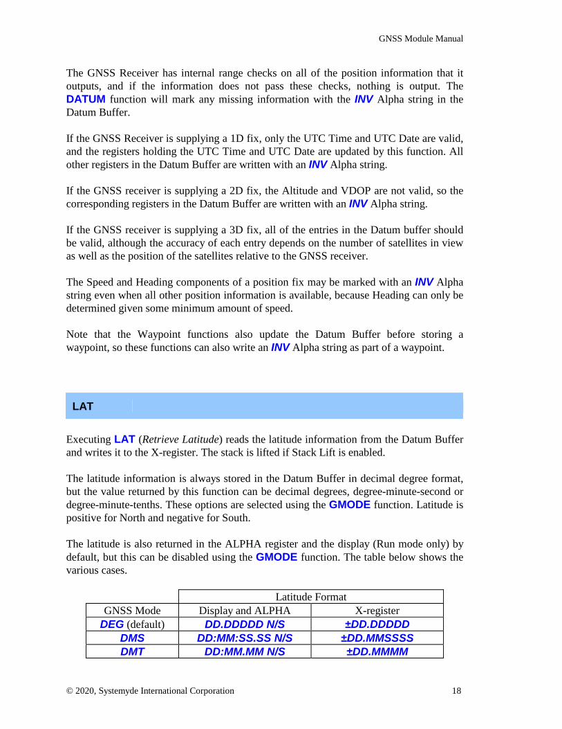
LAT
Executing LAT (Retrieve Latitude) reads the latitude information from the Datum Bufferand writes it to the X-register. The stack is lifted if Stack Lift is enabled.
The latitude information is always stored in the Datum Buffer in decimal degree format,but the value returned by this function can be decimal degrees, degree-minute-second ordegree-minute-tenths. These options are selected using the GMODE function. Latitude ispositive for North and negative for South.
The latitude is also returned in the ALPHA register and the display (Run mode only) bydefault, but this can be disabled using the GMODE function. The table below shows thevarious cases.
Latitude FormatGNSS Mode Display and ALPHA X-register
DEG (default) DD.DDDDD N/S ±DD.DDDDDDMS DD:MM:SS.SS N/S ±DD.MMSSSSDMT DD:MM.MM N/S ±DD.MMMM

GNSS Module Manual
© 2020, Systemyde International Corporation 19
LON
Executing LON (Retrieve Longitude) reads the longitude information from the DatumBuffer and writes it to the X-register. The stack is lifted if Stack Lift is enabled.
The longitude information is always stored in the Datum Buffer in decimal degree format,but the value returned by this function can be decimal degrees, degree-minute-second ordegree-minute-tenths. These options are selected using the GMODE function. Latitude ispositive for East and negative for West.
The longitude is also returned in the ALPHA register and the display (Run mode only) bydefault, but this can be disabled using the GMODE function. The table below shows thevarious cases.
Longitude FormatGNSS Mode Display and ALPHA X-register
DEG (default) DDD.DDDDD E/W ±DDD.DDDDDDMS DDD:MM:SS.SS E/W ±DDD.MMSSSSDMT DDD:MM.MM E/W ±DDD.MMMM
ALTI
Executing ALTI (Retrieve Altitude) reads the MSL (Mean Sea Level) altitude informationfrom the Datum Buffer and writes it to the X-register. The stack is lifted if Stack Lift isenabled.
The altitude information is always stored in the Datum Buffer in meters, but the valuereturned by this function can be meters or feet. These options are selected using theGMODE function.
The altitude is also returned in the ALPHA register and the display (Run mode only) bydefault, but this can be disabled using the GMODE function. The table below shows thetwo cases.
Altitude FormatGNSS Mode Display and ALPHA X-registerM (default) NNNNN M NNNNN
FT NNNNN FT NNNNN
GNSS Module Manual
© 2020, Systemyde International Corporation 20
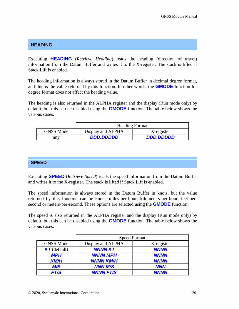
HEADING
Executing HEADING (Retrieve Heading) reads the heading (direction of travel)information from the Datum Buffer and writes it to the X-register. The stack is lifted ifStack Lift is enabled.
The heading information is always stored in the Datum Buffer in decimal degree format,and this is the value returned by this function. In other words, the GMODE function fordegree format does not affect the heading value.
The heading is also returned in the ALPHA register and the display (Run mode only) bydefault, but this can be disabled using the GMODE function. The table below shows thevarious cases.
Heading FormatGNSS Mode Display and ALPHA X-register
any DDD.DDDDD DDD.DDDDD
SPEED
Executing SPEED (Retrieve Speed) reads the speed information from the Datum Bufferand writes it to the X-register. The stack is lifted if Stack Lift is enabled.
The speed information is always stored in the Datum Buffer in knots, but the valuereturned by this function can be knots, miles-per-hour, kilometers-per-hour, feet-per-second or meters-per-second. These options are selected using the GMODE function.
The speed is also returned in the ALPHA register and the display (Run mode only) bydefault, but this can be disabled using the GMODE function. The table below shows thevarious cases.
Speed FormatGNSS Mode Display and ALPHA X-registerKT (default) NNNN KT NNNN
MPH NNNN MPH NNNNKM/H NNNN KM/H NNNNM/S NNN M/S NNNFT/S NNNN FT/S NNNN

GNSS Module Manual
© 2020, Systemyde International Corporation 21
UTIME
Executing UTIME (Retrieve UTC Time) reads the time information from the DatumBuffer and writes it to the X-register. The stack is lifted if Stack Lift is enabled.
The UTC Time in the Datum Buffer is always in the form of hh.mmssss where hh ishours, mm is minutes and ssss is seconds and hundredths of a second. UTC Time isalways in the same format used by the Time Module in the CLK24 format.
In Run mode, the UTC Time is also returned in the display and the ALPHA register. Thetable below shows the various cases.
UTC Time FormatGNSS Mode Display and ALPHA X-register
any HH:MM:SS UTC HH.MMSSSS
UDATE
Executing UDATE (Retrieve UTC Date) reads the date information from the DatumBuffer and writes it to the X-register. The stack is lifted if Stack Lift is enabled.
The UTC Date in the X-register in the Datum Buffer is always in the form of dd.mmyyyywhere dd is day, mm is month and yyyy is year. This is the same format used by the TimeModule when the DMY format is used.
In Run mode, the UTC Date is also returned in the display and the ALPHA register. Thetable below shows the various cases.
UTC Date FormatGNSS Mode Display and ALPHA X-register
any DD/MM/YYYY DD.MMYYYY
SATS
Executing SATS (Retrieve Count of Satellites Used) reads the "satellites used inpositioning calculation" information from the Datum Buffer and writes it to the X-register. The stack is lifted if Stack Lift is enabled.
GNSS Module Manual
© 2020, Systemyde International Corporation 22
The number of satellites used will range from 0 to 12. In general, the higher the numberof satellites used, the higher the quality of the position information, but the best measureof the quality of the position information are the HDOP and VDOP values.
SATIV
Executing SATIV (Retrieve Count of Satellites In View) reads the "satellites in view"information from the Datum Buffer and writes it to the X-register. The stack is lifted ifStack Lift is enabled.
The number of satellites in view will range from 0 to 32. In general, the higher thenumber of satellites in view, the higher the quality of the position information, but thebest measure of the quality of the position information are the HDOP and VDOP values.
GEOID
Executing GEOID (Retrieve Geoidal Separation) reads the geodial separationinformation from the Datum Buffer and writes it to the X-register. The stack is lifted ifStack Lift is enabled.
Geoidal separation is always reported in meters. Refer to WGS-84 for detailedinformation about what geoidal separation means.
HDOP
Executing HDOP (Retrieve Horizontal Dilution of Precision) reads the HDOP valuefrom the Datum Buffer and writes it to the X-register. The stack is lifted if Stack Lift isenabled.
HDOP is a dimensionless measure of the quality of the reported latitude and longitude.Refer to the "GNSS Data Formats" section for an explanation of what a particular HDOPvalue means.

GNSS Module Manual
© 2020, Systemyde International Corporation 23
VDOP
Executing VDOP (Retrieve Vertical Dilution of Precision) reads the VDOP value fromthe Datum Buffer and writes it to the X-register. The stack is lifted if Stack Lift isenabled.
VDOP is a dimensionless measure of the quality of the reported altitude. Refer to the"GNSS Data Formats" section for an explanation of what a particular VDOP valuemeans.

GNSS Module Manual
© 2020, Systemyde International Corporation 24
Waypoint FunctionsThe Waypoint functions are a convenient way to store a snapshot of GNSS data directlyto 41C registers. The 41C registers used for waypoint data are selected either by theWaypoint Pointer Register (WPR) or the contents of the X register, depending on themode selected. The default mode is to use the WPR.
A waypoint requires a minimum of three, and a maximum of eight, registers. The numberof registers used for a waypoint is determined by the function used to store the waypoint,and the waypoint is tagged with an alpha string that identifies the contents of thewaypoint unless you disable the tagging feature. Waypoint data is just normal floatingpoint numbers or an INV Alpha string.
The format of Waypoint data is always identical to the format used in the DatumBuffer: Decimal degrees for latitude, longitude and heading; meters for altitude;knots for speed.
Waypoint data is always stored in a specific order, as shown in the table below. Thestarting register for a waypoint is either the contents of the WPR or the register address(bbb) in the X-register when waypoint function is executed. The default operationincludes the alpha tag in the first register, but this can be disabled to save register space ifyou are always storing the same type of waypoint. This option is completely separatefrom the Waypoint functions.
Register address, relative to WPR or bbbfunction +0 +1 +2 +3 +4 +5 +6 +7
AC "AC" Altitude Heading SpeedACT "ACT" Altitude Heading Speed Time
ACTD "ACTD" Altitude Heading Speed Time DateCT "CT" Heading Speed Time
CTD "CTD" Heading Speed Time DateLL "L" Latitude Long.
LLA "LA" Latitude Long. AltitudeLLAC "LAC" Latitude Long. Altitude Heading Speed
LLACT "LACT" Latitude Long. Altitude Heading Speed TimeLLACTD "LACTD" Latitude Long. Altitude Heading Speed Time Date
LLC "LC" Latitude Long. Heading SpeedLLCT "LCT" Latitude Long. Heading Speed Time
LLCTD "LCTD" Latitude Long. Heading Speed Time DateLLT "LT" Latitude Long. Time
LLTD "LTD" Latitude Long. Time Date

GNSS Module Manual
© 2020, Systemyde International Corporation 25
The different options for the data in a waypoint were selected to support different usecases. For example, if you're on a boat (and not in a lock) you likely don't care aboutaltitude. But if you're in an aircraft you probably should. And the date is only marginallyuseful in many cases.
Certain GNSS information is not available individually in a waypoint. Latitude andlongitude are always reported together, as are heading and speed. Altitude, time and dateare reported individually.
Waypoints can be stored in 41C data memory as long as sufficient registers are available.In addition, waypoint data can be easily transferred from data memory to X-Memory orMass Storage as either individual files or as a combined file.
Executing a Waypoint function automatically updates the Datum Buffer before writingthe waypoint data to 41C registers, so that the individual pieces of position informationare then available for Individual GNSS Data functions without needing to execute theDATUM function.
When using the WPR to hold the register address, after the waypoint is written the WPRis automatically incremented to point at the next available register for a waypoint. Youcan also use the WPR+X function to insert or remove data from a waypoint.
AC (optional register number bbb in X-register)
The AC (Store Altitude/Course Waypoint) function stores the alpha waypoint identifier"AC", plus the GNSS Altitude, Heading and Speed information into four consecutive dataregisters, starting with the register selected either by the WPR or the X-Register. Whenusing the WPR the register number in the WPR is then incremented by four.
ACT (optional register number bbb in X-register)
The ACT (Store Altitude/Course/Time Waypoint) function stores the alpha waypointidentifier "ACT", plus the GNSS Altitude, Heading, Speed and Time information intofive consecutive data registers, starting with the register selected either by the WPR or theX-Register. When using the WPR the register number in the WPR is then incremented byfive.
GNSS Module Manual
© 2020, Systemyde International Corporation 26
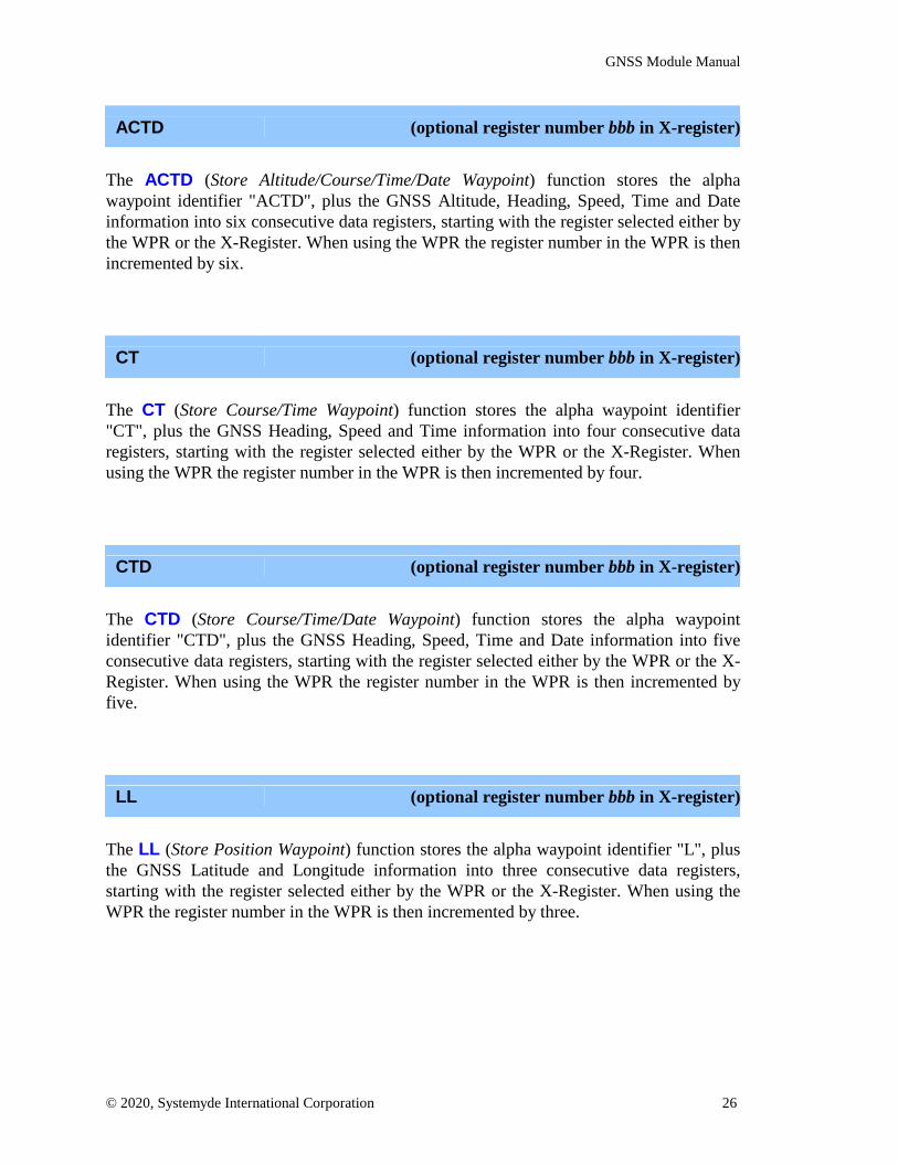
ACTD (optional register number bbb in X-register)
The ACTD (Store Altitude/Course/Time/Date Waypoint) function stores the alphawaypoint identifier "ACTD", plus the GNSS Altitude, Heading, Speed, Time and Dateinformation into six consecutive data registers, starting with the register selected either bythe WPR or the X-Register. When using the WPR the register number in the WPR is thenincremented by six.
CT (optional register number bbb in X-register)
The CT (Store Course/Time Waypoint) function stores the alpha waypoint identifier"CT", plus the GNSS Heading, Speed and Time information into four consecutive dataregisters, starting with the register selected either by the WPR or the X-Register. Whenusing the WPR the register number in the WPR is then incremented by four.
CTD (optional register number bbb in X-register)
The CTD (Store Course/Time/Date Waypoint) function stores the alpha waypointidentifier "CTD", plus the GNSS Heading, Speed, Time and Date information into fiveconsecutive data registers, starting with the register selected either by the WPR or the X-Register. When using the WPR the register number in the WPR is then incremented byfive.
LL (optional register number bbb in X-register)
The LL (Store Position Waypoint) function stores the alpha waypoint identifier "L", plusthe GNSS Latitude and Longitude information into three consecutive data registers,starting with the register selected either by the WPR or the X-Register. When using theWPR the register number in the WPR is then incremented by three.

GNSS Module Manual
© 2020, Systemyde International Corporation 27
LLA (optional register number bbb in X-register)
The LLA (Store Position/Altitude Waypoint) function stores the alpha waypoint identifier"LA", plus the GNSS Latitude, Longitude and Altitude information into four consecutivedata registers, starting with the register selected either by the WPR or the X-Register.When using the WPR the register number in the WPR is then incremented by four.
LLAC (optional register number bbb in X-register)
The LLAC (Store Position/Altitude/Course Waypoint) function stores the alpha waypointidentifier "LAC", plus the GNSS Latitude, Longitude, Altitude, Heading and Speedinformation into six consecutive data registers, starting with the register selected either bythe WPR or the X-Register. When using the WPR the register number in the WPR is thenincremented by six.
LLACT (optional register number bbb in X-register)
The LLACT (Store Position/Altitude/Course/Time Waypoint) function stores the alphawaypoint identifier "LACT", plus the GNSS Latitude, Longitude, Altitude, Heading,Speed and Time information into seven consecutive data registers, starting with theregister selected either by the WPR or the X-Register. When using the WPR the registernumber in the WPR is then incremented by seven.
LLACTD (optional register number bbb in X-register)
The LLACTD (Store Position/Altitude/Course/Time/Date Waypoint) function stores thealpha waypoint identifier "LACTD", plus the GNSS Latitude, Longitude, Altitude,Heading, Speed, Time and Date information into eight consecutive data registers, startingwith the register selected either by the WPR or the X-Register. When using the WPR theregister number in the WPR is then incremented by eight.
GNSS Module Manual
© 2020, Systemyde International Corporation 28
LLC (optional register number bbb in X-register)
The LLC (Store Position/Course Waypoint) function stores the alpha waypoint identifier"LC", plus the GNSS Latitude, Longitude, Heading and Speed information into fiveconsecutive data registers, starting with the register selected either by the WPR or the X-Register. When using the WPR the register number in the WPR is then incremented byfive.
LLCT (optional register number bbb in X-register)
The LLCT (Store Position/Course/Time Waypoint) function stores the alpha waypointidentifier "LCT", plus the GNSS Latitude, Longitude, Heading, Speed and Timeinformation into six consecutive data registers, starting with the register selected either bythe WPR or the X-Register. When using the WPR the register number in the WPR is thenincremented by six.
LLCTD (optional register number bbb in X-register)
The LLCTD (Store Position/Course/Time/Date Waypoint) function stores the alphawaypoint identifier "LCTD", plus the GNSS Latitude, Longitude, Heading, Speed, Timeand Date information into seven consecutive data registers, starting with the registerselected either by the WPR or the X-Register. When using the WPR the register numberin the WPR is then incremented by seven.
LLT (optional register number bbb in X-register)
The LLT (Store Position/Time Waypoint) function stores the alpha waypoint identifier"LT", plus the GNSS Latitude, Longitude, and Time information into four consecutivedata registers, starting with the register selected either by the WPR or the X-Register.When using the WPR the register number in the WPR is then incremented by four.

GNSS Module Manual
© 2020, Systemyde International Corporation 29
LLTD (optional register number bbb in X-register)
The LLTD (Store Position/Time/Date Waypoint) function stores the alpha waypointidentifier "LTD", plus the GNSS Latitude, Longitude, Time and Date information intofive consecutive data registers, starting with the register selected either by the WPR or theX-Register. When using the WPR the register number in the WPR is then incremented byfive.

GNSS Module Manual
© 2020, Systemyde International Corporation 30
Waypoint Housekeeping FunctionsThe Waypoint Housekeeping functions allow you to control where the GNSS waypointsare stored in the 41C register memory, and provide a way to communicate thisinformation to other programs that might use the waypoint data.
Two dedicated registers are implemented inside the 41C GNSS Module to hold pointersto the registers involved in waypoints. The first is called the Waypoint Base Register(WBR), which is used to point to the start of the very first waypoint. The second is calledthe Waypoint Pointer Register (WPR), which is used to point to the start of the nextwaypoint to be stored.
When the 41C GNSS Module is first inserted both the WBR and WPR are initialized tozero, selecting R00 as the first register to be used for waypoint data. Normally the WBRand WPR will be initialized to point at the same register.
If you plan to use the Navigation module to perform calculations using waypoint data,remember that this module uses R00 through R53 to hold intermediate data, so in this caseboth the WBR and WPR should be manually initialized to point at R54 or higher.
If you choose not to use the WBR and WPR, you can also specify the starting register forwaypoint data with a three-digit number in the X-Register. But this requires you to do anybuffer management in software.
GPTRP
Executing GPTRP (Use Waypoint Pointer Register) enables the WPR to be used as theregister pointer by subsequent Waypoint functions. This selection is stored in the GNSSModule as long as the module is inserted in the calculator. This is the default selectionwhen the GNSS Module is first inserted into the calculator.
GPTRX
Executing GPTRX (Use X-Register as pointer) enables the X-Register to be used as theregister pointer by the Waypoint functions. This selection is stored in the GNSS Moduleas long as the module is inserted in the calculator.

GNSS Module Manual
© 2020, Systemyde International Corporation 31
RCLWBR
Executing RCLWBR (Recall Waypoint Base Register) copies the WBR contents to theX-register. The stack is lifted if Stack Lift is enabled.
The contents of the X-register can then be used directly, using stack-indirect addressing,to fetch the first stored waypoint register. There is no check that waypoint data has everbeen written, so that should be done before attempting to access waypoint data.
STOWBR (register number rrr in X-register)
Executing STOWBR (Store Waypoint Base Register) writes the contents of the X-register to the WBR. The contents of the X-register are unaffected by this operation.
The WBR is initialized with 0 when the 41C GNSS Module is first inserted in thecalculator. The WBR is used only for reference to the start of the waypoint data, and isnever modified by the GNSS Software.
RCLWPR
Executing RCLWPR (Recall Waypoint Pointer Register) copies the WPR contents to theX-register. The stack is lifted if Stack Lift is enabled.
Because the WPR points at the start of the next waypoint, the contents of the X-registerwill need to be modified before it can be used, using stack-indirect addressing, to fetchany stored waypoint data. There is no check that waypoint data has ever been written, sothat should be done before attempting to access waypoint data.
STOWPR (register number rrr in X-register)
Executing STOWPR (Store Waypoint Pointer Register) writes the contents of the X-register to the WPR. The contents of the X-register are unaffected by this operation.
The WPR is initialized with 0 when the 41C GNSS Module is first inserted in thecalculator. The WPR is automatically incremented after a waypoint is stored, to point at

GNSS Module Manual
© 2020, Systemyde International Corporation 32
the next available register.
WPR+X (offset bbb in X-register)
Executing WPR+X (Add X to Waypoint Pointer Register) adds the contents of the X-register to the WPR. The contents of the X-register are unaffected by this operation.
If the value in the X-register is positive, this creates available slots, either at the beginningof the next waypoint, or at the end of the current waypoint, that can be used to holdauxiliary information in the waypoint. If the value in the X-register is negative, thisremoves entries at the end of the current waypoint. No range checks are done before orafter this addition.
RCLRNG
Executing RCLRNG (Recall Waypoint Register Range) reads the WBR and WPR andforms a number of the form bbb.eee which is written to the X-register. The stack is liftedif Stack Lift is enabled.
This number can be used directly by the SAVERX function (in the 41C ExtendedFunctions) to write all of the waypoint data to X-Memory or by the WRTRX function (inthe HP-IL Module) to write all of the waypoint data to mass storage.
If there is no valid waypoint data, because integer part of WPR is less than or equal to theinteger part of WBR, the X-register is written with 999.999. This value will then generatean error if you attempt to use it with either the SAVERX function or the WRTRXfunction.

GNSS Module Manual
© 2020, Systemyde International Corporation 33
Miscellaneous FunctionsThe Miscellaneous functions provide a conversion from decimal degrees and set andquery the mode control options for the GNSS Software.
DMT
Executing DMT (Convert to Degrees-Minutes-Tenths) converts the decimal degrees inthe X-register to dd.mmmmmm format in the X-register. The sign of the value ispreserved. No range check is performed prior to this conversion. There is an implicitdecimal point after the first two digits of the minutes field.
To convert from decimal degrees to degree-minute-second format, use the built-in 41CHMS function.
GMODE (mode selects in ALPHA register)
Executing GMODE (Set GNSS Mode) sets the GNSS operating mode according to themode identifiers in the ALPHA register.
Mode identifiers must be separated by a space and can be in any order. The modeidentifiers are scanned from right to left in the ALPHA register, and the ALPHA registeris cleared by this function. These modes are stored within the GNSS Module and areretained as long as the module is powered.
Invalid mode identifiers are ignored, and are removed from the ALPHA register just likevalid mode identifiers.
All Individual GNSS Data functions return data to the X-register, but a number of thesefunctions can also return the data, with a units identifier, to the display and the ALPHAregister by default. This feature can be disabled using the NOA mode identifier. In thismode the number is merely returned to the X-register without any units identifier.
Functions Identifier Meaning default
Individual GNSSData Functions
ALPNOA
Written to ALPHA/displayNot written to ALPHA/display
ALP

GNSS Module Manual
© 2020, Systemyde International Corporation 34
All Waypoint functions normally include an alpha identifier stored with each waypoint.This option can be disabled using the RAW mode identifier, which saves space, butmeans that there will be no indication of exactly what information is contained in thewaypoint or how many registers the waypoint is using.
Functions Identifier Meaning default
Waypoint FunctionsTAGRAW
Tag each waypointNo waypoint tag
TAG
None of the modes below that select units affect waypoint data. The format ofWaypoint data is ALWAYS identical to the format used in the Datum Buffer:Decimal degrees for latitude, longitude and heading; meters for altitude; knots forspeed. This is a concious design decision. Remember the Mars Climate Orbiter? Beextremely careful calculating with data from Individual GNSS Data functions if you everchange the units for those functions! The tables below show the mode identifiersavailable for the different cases.
Individual GNSS functions that return latitude or longitude default to decimal degrees.Heading is always reported in decimal degrees, independent of the degrees identifier.
Functions Identifier Meaning default
LATLON
DEGDMSDMT
decimal degreesdegree-minute-seconddegree-minute-tenths
DEG
The ALTI function returns the altitude information in meters by default.
Functions Identifier Meaning default
ALTI MFT
metersfeet
M
The SPEED function returns the speed information in knots by default.
Function Identifier Meaning default
SPEED
KTMPHKM/HM/SF/S
knotsmiles/hour
kilometers/hourmeters/second
feet/second
KT

GNSS Module Manual
© 2020, Systemyde International Corporation 35
Different use cases for the GNSS Module will need different mode settings. For example,if you are in an automobile in the US, you will probably want to know your speed inMPH and your altitude in feet:
"MPH FT"XEQ "GMODE"
In an automobile elsewhere in the world, you will probably want your speed in KM/H:
"KM/H"XEQ "GMODE"
An aircraft will usually want altitude in feet and latitude/longitude in DMT:
"FT DMT"XEQ "GMODE"
GMODE*
Executing GMODE* (Set Default GNSS Modes) sets the GNSS modes to the default ofKT DEG M TAG ALP. This function does not affect the choice of Waypoint Pointer orany of the ROM options.
GMODE?
Executing GMODE? (Query GNSS Modes) returns the current set of GNSS modes in theALPHA register. Modes are returned in a specific order, with each identifier separated bya space.
For example, the default modes will be returned as KT DEG M TAG ALP. Somecombinations of modes are too long for the display, and will scroll left.
If you have changed the mode as shown in the GMODE examples above, GMODE? willreturn the following:
US automobile: MPH DEG FT TAG ALP
GNSS Module Manual
© 2020, Systemyde International Corporation 36
Rest of world automobile: KM/H DEG M TAG ALP
Aircraft: KT DMT FT TAG ALP
GCLOCK
Executing GCLOCK (Enable GNSS Clock Display) enables the continuous display of theGNSS time, just like the CLOCK function does for the Time Module.
This function automatically enables the GNSS receiver. If the GNSS receiver was notalready enabled the calculator will enter deep sleep mode and the clock display will notstart until a 1-D fix is available.
The clock display is cancelled by pressing any key. Pressing any key except for ON willcause the GNSS receiver to enter Standby mode. Pressing the ON key will cancel the timedisplay but the GNSS receiver will remain active.
If a low battery condition is detected, either while waiting for a 1-D fix, or during theclock display, the GNSS receiver will be disabled and the calculator will beep and turnoff.
This function does not update the DATUM buffer.

GNSS Module Manual
© 2020, Systemyde International Corporation 37
ROM Option FunctionsThe ROM Option functions control the operation of the ROM in the GNSS Module.
DISROM
Executing DISROM (Disable GNSS Module ROM) disables the software internal to theGNSS Module. This function should only be used in cases where some other source ofGNSS software is available to be executed in place of the code in the GNSS Module.
ENROM
Executing ENROM (Enable GNSS Module ROM) enables the software internal to theGNSS Module. This function obviously can only be used in cases when the currentsource of GNSS Software is external to the GNSS Module itself.
This function is also used to return the internal ROM to read-only mode after having beenenabled for writing with the WRROM function.
RELROM (page number p in X-register)
The RELROM (Relocate GNSS Module ROM) modifies the address decoder in theGNSS Module to relocate the GNSS Software. Only pages 6-15 are valid relocationtargets. This function does check for occupied pages before attempting the relocation, andreturns a DATA ERROR error message if a collision is detected.
WRROM
Executing WRROM (Enable Writeable GNSS Module ROM) enables the ROM in theGNSS Module for writes. This feature allows patching or even complete replacement ofthe GNSS Software. This patching or replacement is only stored as long as power isapplied to the module.
GNSS Module Manual
© 2020, Systemyde International Corporation 38
Direct Communication FunctionsThe Direct Communication functions allow you to directly access the registers in theGNSS Module, including the 512-byte FIFOs connected to the internal serial port.
GPEEK (register number r in X-register)
Executing GPEEK (Read GNSS Control Register) reads the GNSS module registerselected by the number in the X-register. The register read is in the 0xF1 peripheral pageand the register number can range from 0 through 15.
The read data is returned as 14 hexadecimal digits in the ALPHA register, which replacesany data present in the ALPHA register.
GPOKE (register number r in X-register, hex data in ALPHA)
Executing GPOKE (Write GNSS Control Register) writes the GNSS module registerselected by the number in the X-register with the hexadecimal number in the ALPHAregister. The register written is in the 0xF1 page and the register number can range from 0through 15.
The fourteen least-significant digits in the ALPHA register are used, and the ALPHAregister is not disturbed by this function. Leading zeros do not need to be present in thehex number in ALPHA.
GRDA
Executing GRDA (Read GNSS Receive Buffer as Alpha) reads the inbound buffer onetime and appends this data as alpha characters, in received byte order, to the ALPHAregister. If the ALPHA register is full appended characters push characters off of themost-significant end of the ALPHA register.
The number of characters appended to the ALPHA register ranges from 1 to 4. Thenumber of characters appended to the ALPHA register is added to the contents of the X-register.
GNSS Module Manual
© 2020, Systemyde International Corporation 39
GRDH
Executing GRDH (Read GNSS Receive Buffer as Hex) reads the inbound buffer one timeand appends the hex data, in received byte order, to the ALPHA register. If the ALPHAregister is full appended bytes push characters off of the most-significant end of theALPHA register.
Each received character requires two bytes to display in the ALPHA register, so thenumber of bytes appended to the ALPHA register is 2, 4, 6 or 8. The number of bytes(divided by two, for the number of characters) appended to the ALPHA register is addedto the contents of the X-register.
GWRA (character data in ALPHA)
Executing GWRA (Write GNSS Transmit Buffer as Alpha) writes to the outbound bufferusing the contents of the ALPHA register directly. Up to 24 characters (the width of theALPHA register) will be written by this function.
The characters in the ALPHA register are written so that they will be transmitted startingwith the most-significant character first. The characters are removed from the ALPHAregister as they are written to the buffer.
The ALPHA register treats the byte 0x00 as special. If you need to write 0x00 bytes to thebuffer, it is best to use the GWRH function for those bytes.
GWRH (hex data in ALPHA)
Executing GWRH (Write GNSS Transmit Buffer as Hex) writes to the outbound bufferusing the contents of the ALPHA register, which is assumed to hold hexadecimal data.Each transmitted byte requires two characters in the ALPHA register to represent a byte.Up to twelve bytes can be written to the buffer by this function.
The hex data in the ALPHA register is written so that it will be transmitted starting withthe most-significant byte first. The hex data is removed, two characters at a time, from theALPHA register. In the case of an odd number of characters in the ALPHA register, thefinal character will be written as the most-significant nibble of a byte, with the least-significant nibble of 0.

GNSS Module Manual
© 2020, Systemyde International Corporation 40
Error ConditionsThe functions in the GNSS Module almost all deal with simply reading data from theGNSS Receiver, and as a result there are not a lot of possible error conditions. The tablebelow lists all possible error messages returned by functions in the GNSS Module, alongwith the meaning of the message.
Error Message Function Meaning
ALPHA DATA
STOWBRSTOWPRWPR+X
DMT
Operation attempted on Alpha data
BFR EMPT GRDAGRDH
Inbound buffer is empty
BFR FULL GWRAGWRH
Outbound Buffer is full
BFR OV GRDAGRDH
Inbound buffer overflowed
STOWBRSTOWPRWPR+X
Number larger than 999
GPOKEGWRH
Invalid hex numberDATA ERROR
GWRAGWRH
ALPHA register empty
STOWBRSTOWPRWPR+X
Register does not exist
GPOKEGPEEK
Invalid register selectOUT OF RANGE
All Waypointfunctions
Required registers exceed highestnumbered data storage register
REL ERROR RELROMAttempt to relocate ROM
to an invalid or occupied page
GNSS OFFDATUM
All Waypointfunctions
GNSS Module in Deep Sleep state

GNSS Module Manual
© 2020, Systemyde International Corporation 41
While it is not an error condition, invalid or missing data in a NMEA string will result inan Alpha string INV being written to the Datum Buffer in place of a number. This Alphastring will also be transferred to a register as part of a Waypoint function. Certain invaliddata will affect more than just the individual GNSS data, as will a too-long NMEA string,along with other conditions, according to the table below.
Condition Datum entries marked as INVGNSS receiver off
RMC stringmarked InvalidInvalid UTIMEInvalid UDATE
all
RMC stringtoo long
Invalid LATInvalid LON
LAT LON SPEED HEADING
GGA stringtoo long or missing ALTI SATS GEOID
GSA stringtoo long or missing HDOP VDOP
GSV stringtoo long or missing SATIV

GNSS Module Manual
© 2020, Systemyde International Corporation 42
Internal DetailsThe GNSS Module appears to the MCODE programmer as a set of peripheral registersthat can be accessed after the correct peripheral address is selected. The table belowshows the peripheral addresses currently used in the 41C ecosystem.
PeripheralAddress Usage
0xF0 41CL on-chip0xF10xF2
GNSS Module
0xFB Time Module0xFC Card Reader0xFD LCD Display0xFE Barcode Wand
The table below shows the peripheral registers in page 0xF1 in the GNSS Module that arevisible to the MCODE programmer. Writes to read-only registers are ignored. Reads fromwrite-only registers return all zeros. The unimplemented registers always return all zeroson read, and writes to these unimplemented registers are ignored.
The registers in page 0xF1 can be accessed from the keyboard or in a program using theDirect Communication functions GPEEK, GPOKE, GRDA, GRDH, GWRA andGWRH.
Register Usage Read/Write comments0 String Buffer Control yes1 String Buffer Data read-only dual 1536-byte RAMs2 String Buffer Claim write-only3 String Buffer Release write-only4 GNSS Control/Status yes5 ROM Control yes6 Scratch 1 yes7 Scratch 2 yes8 Inbound Buffer Control/Status yes9 Inbound Buffer Data read-only 512-byte FIFO10 reserved11 reserved12 Outbound Buffer Control/Status yes13 Outbound Buffer Data write-only 512-byte FIFO14 reserved15 reserved

GNSS Module Manual
© 2020, Systemyde International Corporation 43
Page 0xF2 contains sixteen general-purpose read/write registers that are used to hold theDATUM information as well as the Waypoint pointer registers, as shown in the tablebelow.
The registers in page 0xF2 cannot be accessed directly from the keyboard or in a program.
Register Usage Source0 WBR software1 WPR software2 Time RMC3 Date RMC4 Latitude RMC5 Longitude RMC6 Speed RMC7 Heading RMC8 Position Fix Indicator GGA9 Satellites Used GGA10 MSL Altitude GGA11 Geodial Separation GGA12 Mode 2 GSA13 HDOP GSA14 VDOP GSA15 Satellites In View GSV
The receiver in the GNSS Module outputs position information as serial strings of ASCIIcharacters according to the NMEA-0183 standard. All NMEA strings start with the "$"character and end with "<CR><LF>" so they are easy to recognize in hardware. Hardwarein the GNSS Module routes the NMEA strings required by the GNSS software to adedicated string buffer to make it easier for software to find the necessary positioninformation.
The string buffer is 1536 bytes deep, and is divided into twelve 128-byte segments. EachNMEA string is written to a separate segment so that software does not need to searchthrough NMEA strings but can access the desired string directly.
There are actually two string buffers, and the hardware automatically alternates betweenbuffers, which allows the receiver to continue writing position information to a bufferwhile the software is reading the position information from the other buffer.
When the software wants to read a buffer it "claims" the buffer so that the receiver cannotoverwrite the position information, and then "releases" the buffer after all of the data hasbeen read. In the event that the receiver needs to start another buffer while it is locked outof one buffer, the unlocked buffer is automatically reused. This buffer management is

GNSS Module Manual
© 2020, Systemyde International Corporation 44
completely transparent to the user. There is no need to select which buffer to claim orread.
The hardware switches string buffers when the first NMEA message in a sequence isrecognized. For the receiver used in the GNSS Module this is the RecommendedMinimum Specific GNSS Data (RMC) string. This string contains the UTC time, statusindicator, latitude, longitude, speed, course, UTC date, a couple of unused fields and achecksum. The GNSS Module software uses all of the fields in this string.
The Global Positioning System Fix Data (GGA) string contains the UTC time, latitude,longitude, position indicator, satellites used, horizontal dilution of precision, MSLaltitude, geoidal separation, a couple of unused fields and a checksum. The GNSSModule software only uses the satellites used, MSL altitude and geoidal separationinformation in this string.
The GNSS Satellites in View (GSV) string contains information about the number andidentity of satellites in view by the receiver. Only the information about the number ofsatellites in view is used by the GNSS module. The receiver can output up to four GSVstrings, which are buffered separately in the string buffer.
The GNSS DOP and Active Satellites (GSA) string contains information about thenumber and identity of satellites used in the position fix, along with information about thedilution of precision for all three directions. This string is used by the hardware in theGNSS module to report the type of fix (2D or 3D) being reported. The receiver can outputmultiple GSA strings, but only the first and second are buffered in the string buffer.
If there are any other NMEA strings output by the receiver, they are automaticallybuffered in two uncommitted segments in the string buffer. If there are more than two ofthese extra strings, those beyond the first two are ignored.
The string buffers are linear (not recirculating) and are random-access as far as thesoftware is concerned. The table below shows how the segments are organized. Note thatthe string headers (the first six bytes of a string, "$GPRMC" for example) of recognizedstrings are not written to the string buffer. Only the first bytes (those needed to distinguishan unrecognized header) of an unrecognized string are not written to the string buffer.
segment Usage0x0 RMC string0x1 VTG string0x2 GLL string0x3 GGA string0x4 other #10x5 other #20x6 GSA string #10x7 GSA string #2

GNSS Module Manual
© 2020, Systemyde International Corporation 45
0x8 GSV string #10x9 GSV string #20xA GSV string #30xB GSV string #4
The string buffer being filled by the receiver is automatically released (so that it can thenbe claimed by the GNSS Software) when an idle line is detected on the receiver output.For the GNSS Module an idle line is defined as 32 consecutive "1" bits. Since the GNSSReceiver synchronizes its NMEA output strings to an internal one-second tick, thereceiver output is guaranteed to go idle after all of the NMEA strings for one update havebeen sent by the GNSS Receiver. With the default serial data rate of 38400 bits/sec,eighty bytes per string, and ten output strings, the GNSS receiver output will be active foronly about 210mS out of each second.
There are two error conditions that will also cause a release of the string buffer. Theseerror conditions should never occur in the GNSS Module, simply because the connectionbetween the GNSS Receiver and the remainder of the logic in the GNSS Module is shortand in a benign environment. But if a NMEA string exceeds 80 bytes in length the stringbuffer will be released and the logic will wait for the next RMC string to again claim astring buffer and start writing the NMEA information. The string buffer will also bereleased if a second RMC string is received before an idle line has been detected.
A separate buffer, called the inbound buffer, holds all messages from the receiver that arenot NMEA strings. This buffer is implemented as a FIFO for both receiver and thesoftware. This buffer can optionally be enabled for NMEA strings, although this option isnot recommended because it is difficult for the 41C processor to keep up with the datarate output by the receiver.
There is also an outbound buffer, used for control messages destined for the receiver.This buffer is implemented as a FIFO for both the receiver and the software.
A loopback option is available for testing the GNSS module. In this mode the output ofthe transmitter is fed back to the receiver, completely bypassing the GNSS receiver. Thisallows arbitrary NMEA strings to be sent through the receive path.
The register interface to these buffers and the associated control and status are describedbelow. All unused register bits and nibbles will return zero when read, and writes to theunused bits and nibbles are ignored.

GNSS Module Manual
© 2020, Systemyde International Corporation 46
String Buffer Control
Register 0 is the String Buffer Control register:
13 12 11 10 9 8 7 6 5 4 3 2 1 0rw rw
0 0 0 0 0 0 0 0 0 saddr seg 0 0
Nibbles 4 and 3 are used to address the locations in the selected segment of the StringBuffer to be read. These nibbles are read/write. The address of the first received byte in astring is 0x00. Since NMEA strings are limited to eighty bytes, the last byte of a stringshould be at or before address 0x4F and the remainder of the segment should not containany valid NMEA data. Bit 7 of the address byte is ignored. The address byte isautomatically incremented by seven whenever the String Buffer Data register is read, sothat it only needs to be written once, when starting to access a segment in the buffer.
saddr byte Usage
0x00 First received byte(the "," after the string ID)
0x01-0x4F Subsequent received bytes,in order
0x50-0x7F Should be empty
Nibble 2 is used to select the segment of the String Buffer to be read according to thetable below. This nibble is read/write. Segment numbers greater than 11 (0xB) are invalidand will result in all zeros being read from the buffer.
seg nibble Usage0x0 RMC string0x1 VTG string0x2 GLL string0x3 GGA string0x4 unrecognized #10x5 unrecognized #20x6 GSA string #10x7 GSA string #20x8 GSV string #10x9 GSV string #20xA GSV string #30xB GSV string #4
0xC-0xF Invalid selection

GNSS Module Manual
© 2020, Systemyde International Corporation 47
The two segments reserved for "unrecognized" strings will be used for the first tworeceived strings that do not have a dedicated slot in the string buffer.
String Buffer Data
Register 1 is the String Buffer Data register:
13 12 11 10 9 8 7 6 5 4 3 2 1 0r r r r r r r
byte 6 byte 5 byte 4 byte 3 byte 2 byte 1 byte 0
Byte 0 is the first received byte, followed in order by byte 1, byte 2, byte 3 and so on.NMEA strings to not have a guaranteed length, but are delimited by <CR><LF> so thatsoftware can determine the end of the string. Data returned after <CR><LF> is invalid,because the string buffer is never initialized.
The string headers (the first six bytes of a string, ("$GPRMC" for example) of recognizedstrings are not written to the string buffer. All header bytes up to the first unrecognizedbyte of an unrecognized string are not written to the string buffer. For example, a stringthat starts with "$GPTXT" will buffer the "TXT" portion of the header to the stringbuffer. This allows software to fully decode any "unrecognized" strings.
String Buffer Claim
Register 2 is the String Buffer Claim trigger. Writing any value to this register claims themost-recently-filled String Buffer for the software. Once a string buffer is claimed theString Buffer Valid bits in the GNSS Control/Status register are valid and the StringBuffer Data register can be accessed.
String Buffer Release
Register 3 is the String Buffer Release trigger. Writing any value to this register removesthe claim on the String Buffer by the software.

GNSS Module Manual
© 2020, Systemyde International Corporation 48
GNSS Control/Status
Register 4 is the GNSS Control/Status register:
13 12 11 10 9 8 7 6 5 4 3 2 1 0r r rw r rw
0 0 0 0 0 0 segval tid pwr rcv hmd 0
Nibbles 7-5 are the "valid" status bits for the segments in the claimed string buffer. Alltwelve of these bits are cleared when the receiver claims a string buffer and thenindividual valid bits are set when the corresponding string is received. This allowssoftware to handle the case where not every string is received during a GNSS outputmessage. A set of these bits exists for each string buffer, and claiming the string bufferautomatically selects the appropriate set of bits. The table below shows which bitcorresponds to which segment.
segval bit Usage0 RMC string valid1 VTG string valid2 GLL string valid3 GGA string valid4 unrecognized #1 valid5 unrecognized #2 valid6 GSA string #1 valid7 GSA string #2 valid8 GSV string #1 valid9 GSV string #2 valid10 GSV string #3 valid11 GSV string #4 valid
Nibble 4 contains the talker ID for the current string buffer. This information is latchedduring the RMC string for each string buffer and the appropriate set of status is returnedafter the software claims the string buffer. The table below shows the encoding of thisnibble. Only the bit combinations shown will ever be returned.
tid talker0100 GPS ($GP string)0010 other ($GN string)0001 GLONASS ($GL string)
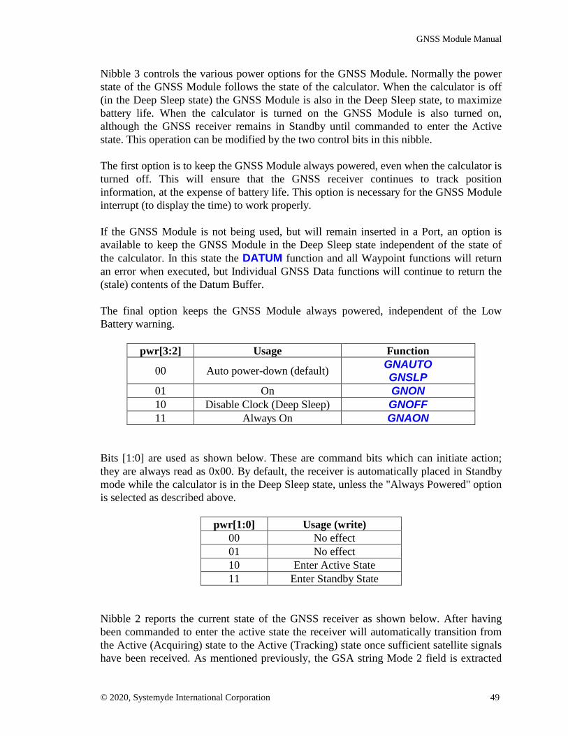
GNSS Module Manual
© 2020, Systemyde International Corporation 49
Nibble 3 controls the various power options for the GNSS Module. Normally the powerstate of the GNSS Module follows the state of the calculator. When the calculator is off(in the Deep Sleep state) the GNSS Module is also in the Deep Sleep state, to maximizebattery life. When the calculator is turned on the GNSS Module is also turned on,although the GNSS receiver remains in Standby until commanded to enter the Activestate. This operation can be modified by the two control bits in this nibble.
The first option is to keep the GNSS Module always powered, even when the calculator isturned off. This will ensure that the GNSS receiver continues to track positioninformation, at the expense of battery life. This option is necessary for the GNSS Moduleinterrupt (to display the time) to work properly.
If the GNSS Module is not being used, but will remain inserted in a Port, an option isavailable to keep the GNSS Module in the Deep Sleep state independent of the state ofthe calculator. In this state the DATUM function and all Waypoint functions will returnan error when executed, but Individual GNSS Data functions will continue to return the(stale) contents of the Datum Buffer.
The final option keeps the GNSS Module always powered, independent of the LowBattery warning.
pwr[3:2] Usage Function
00 Auto power-down (default) GNAUTOGNSLP
01 On GNON10 Disable Clock (Deep Sleep) GNOFF11 Always On GNAON
Bits [1:0] are used as shown below. These are command bits which can initiate action;they are always read as 0x00. By default, the receiver is automatically placed in Standbymode while the calculator is in the Deep Sleep state, unless the "Always Powered" optionis selected as described above.
pwr[1:0] Usage (write)00 No effect01 No effect10 Enter Active State11 Enter Standby State
Nibble 2 reports the current state of the GNSS receiver as shown below. After havingbeen commanded to enter the active state the receiver will automatically transition fromthe Active (Acquiring) state to the Active (Tracking) state once sufficient satellite signalshave been received. As mentioned previously, the GSA string Mode 2 field is extracted

GNSS Module Manual
© 2020, Systemyde International Corporation 50
by the hardware to report the receiver state in this field.
rcv Usage (read)0000 Standby (default)0001 Active (Acquiring)0010 Active (2D fix)0100 Active (3D fix)
Nibble 1 contains hardware mode controls. Bits [3:1] control the serial data rate to andfrom the GNSS Receiver. This selection does not program the GNSS Receiver, onlythe hardware in the GNSS Module. A special control message to the GNSS Receiver isrequired to change the serial data rate used by the receiver.
hmd[3:1] Usage GMODE identifier000 38400 (default) 384001 38400 with loopback LP100 19200 192101 9600 96110 4800 48
Bit 0 of nibble 1 controls the GNSS Module interrupt. When enabled, the GNSS Modulewill wake up the calculator from Deep Sleep or Light Sleep when the following threeconditions are all met: the RMC string Status field is "A" signifying data valid, the GSAstring Mode 2 field is "3" signifying a 3D fix, and the receiver has released the stringbuffer. The interrupt is cleared by disabling the interrupt.
The GNSS Module interrupt is reported using the Flag input to the CPU during the nibble3 time slot on the 41C bus.

GNSS Module Manual
© 2020, Systemyde International Corporation 51
ROM Control
Register 5 is the ROM Control register:
13 12 11 10 9 8 7 6 5 4 3 2 1 0rw rw
0 0 0 0 0 0 0 0 0 0 0 rel rm 0
Nibble 2 relocates the ROM from its default page address of 0xF. Only 0x6 through 0xFare valid page addresses.
rel Usage0x0-0x5 Illegal0x6-0xE Page 6 - E
0xF Page F (default)
Nibble 1 controls the operation of the ROM. Only bits [3:2] are used. By default theROM is read-only, but this control nibble allows the GNSS Software to be patched orcompletely replaced, if necessary. Use the WROM instruction to write to the ROM.
rm[3:2] Enable Mode00 enabled read-only01 enabled read/write1x disabled n/a

GNSS Module Manual
© 2020, Systemyde International Corporation 52
Scratch 1
Register 6 is a general-purpose read-write register. This register is used to hold modeinformation for the GNSS software. Refer to the GNSS software listing for the current bitassignments. Some bits are used for debug, so be careful if writing to this register.
13 12 11 10 9 8 7 6 5 4 3 2 1 0rw rw rw rw rw rw rw rw rw rw rw rw rw rw
Scratch 2
Register 7 is a general-purpose read-write register. This register is used by the GCLOCKfunction to hold the current time.
13 12 11 10 9 8 7 6 5 4 3 2 1 0rw rw rw rw rw rw rw rw rw rw rw rw rw rw

GNSS Module Manual
© 2020, Systemyde International Corporation 53
Inbound Buffer Control/Status
Register 8 is the Inbound Buffer Control register:
13 12 11 10 9 8 7 6 5 4 3 2 1 0r r r/w w
0 0 0 0 0 0 0 0 ifill ist im cli
Nibbles 5, 4 and 3 report the fill level of the inbound buffer, which is in the range of zero(0x000) through 512 (0x200). The reported fill level is frozen at the start of a read of thisregister, so there may actually be one more byte in the buffer by the time the fill level isreported.
ifill Usage (rd-only)0x000-0x200 Bytes available0x201-0xFFF illegal
Nibble 2 reports the empty/overflow status of the inbound buffer. If the buffer overflowsonly the last byte in the buffer is overwritten, but once software starts reading dataanything after 511 bytes cannot be considered valid and the buffer should be purged.
ist Usage (rd-only)0000 Buffer empty0001 Buffer not empty1000 Buffer overflowed, is now empty1001 Buffer overflowed, is not empty
Nibble 1 controls what is routed to the inbound buffer. Only bit [3] is used.
im[3] Usage0 No NMEA data (default)1 All data to inbound buffer
Nibble 0 is used to purge the inbound buffer. Only bit [0] is used. A purge should only benecessary if the buffer overflows because the CPU is not able to keep up with incomingdata. This nibble is always read as 0x0.
cli[0] Usage (wr-only)0 No Effect1 Purge Inbound Buffer

GNSS Module Manual
© 2020, Systemyde International Corporation 54
Inbound Buffer Data
Register 9 is the Inbound Buffer Data register:
13 12 11 10 9 8 7 6 5 4 3 2 1 0r r r r r
0 0 0 byte 3 byte 2 byte 1 byte 0 val 0 0
Byte 0 is the first received byte, followed in order by byte 1, byte 2 and byte 3.
Nibble 2 reports the number of valid bytes being transferred. Only bits [2:0] are used. Amaximum of four bytes are transferred with each read of this register so there are onlyfive possible bit combinations returned for this status. This status is read-only.
val[2:0] Usage (rd-only)000 Buffer empty001 Only byte 0 valid010 Only bytes 1-0 valid011 Only bytes 2-0 valid100 Four bytes valid
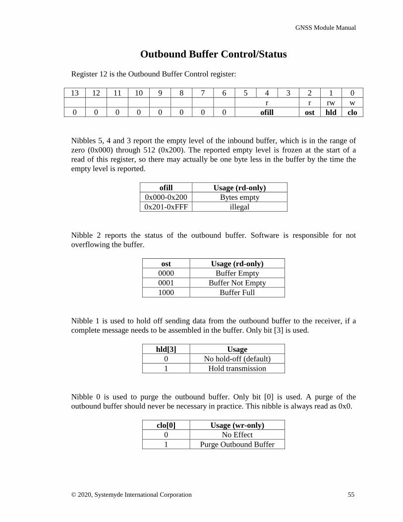
GNSS Module Manual
© 2020, Systemyde International Corporation 55
Outbound Buffer Control/Status
Register 12 is the Outbound Buffer Control register:
13 12 11 10 9 8 7 6 5 4 3 2 1 0r r rw w
0 0 0 0 0 0 0 0 ofill ost hld clo
Nibbles 5, 4 and 3 report the empty level of the inbound buffer, which is in the range ofzero (0x000) through 512 (0x200). The reported empty level is frozen at the start of aread of this register, so there may actually be one byte less in the buffer by the time theempty level is reported.
ofill Usage (rd-only)0x000-0x200 Bytes empty0x201-0xFFF illegal
Nibble 2 reports the status of the outbound buffer. Software is responsible for notoverflowing the buffer.
ost Usage (rd-only)0000 Buffer Empty0001 Buffer Not Empty1000 Buffer Full
Nibble 1 is used to hold off sending data from the outbound buffer to the receiver, if acomplete message needs to be assembled in the buffer. Only bit [3] is used.
hld[3] Usage0 No hold-off (default)1 Hold transmission
Nibble 0 is used to purge the outbound buffer. Only bit [0] is used. A purge of theoutbound buffer should never be necessary in practice. This nibble is always read as 0x0.
clo[0] Usage (wr-only)0 No Effect1 Purge Outbound Buffer

GNSS Module Manual
© 2020, Systemyde International Corporation 56
Outbound Buffer Data
Register 13 is the Outbound Buffer Data register:
13 12 11 10 9 8 7 6 5 4 3 2 1 0w w w w w
0 0 0 byte 3 byte 2 byte 1 byte 0 val 0 0
Byte 0 is the first transmitted byte, followed in order by byte 1, byte 2 and byte 3.
Nibble 2 controls the number of valid bytes being transferred. Only bits [2:0] are used. Amaximum of four bytes are transferred with each write of this register so there are onlyfour possible bit combinations allowed. This nibble is always read as 0x0.
val[2:0] Usage (wr-only)000 No data written001 Only byte 0 valid010 Only bytes 1-0 valid011 Only bytes 2-0 valid100 Four bytes valid
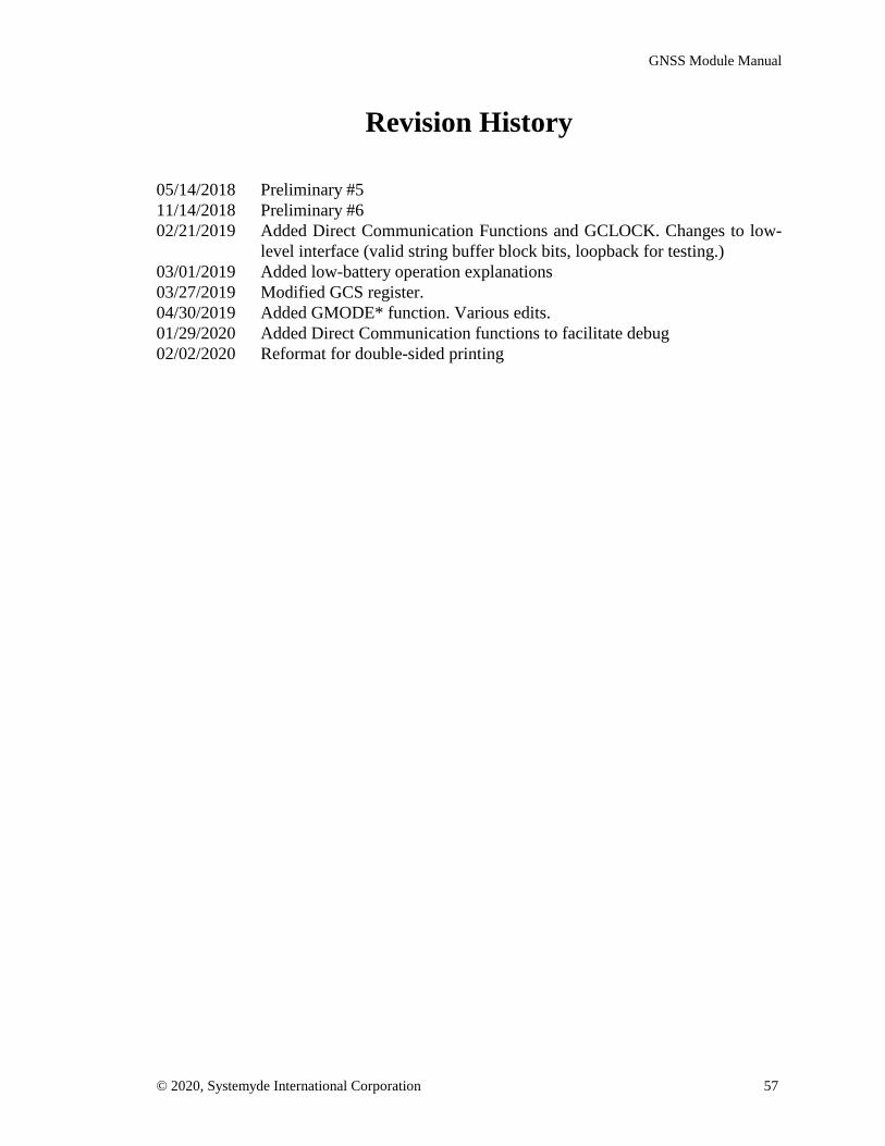
GNSS Module Manual
© 2020, Systemyde International Corporation 57
Revision History
05/14/2018 Preliminary #511/14/2018 Preliminary #602/21/2019 Added Direct Communication Functions and GCLOCK. Changes to low-
level interface (valid string buffer block bits, loopback for testing.)03/01/2019 Added low-battery operation explanations03/27/2019 Modified GCS register.04/30/2019 Added GMODE* function. Various edits.01/29/2020 Added Direct Communication functions to facilitate debug02/02/2020 Reformat for double-sided printing