GLAST Proposal Review - Welcome to SCIPPscipp.ucsc.edu/outreach/hartmut/Pubs/F2k_GLAST_Rad_T.pdf ·...
23
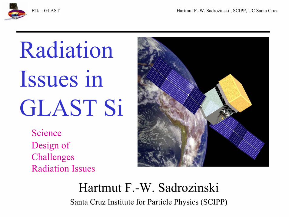
F2k : GLAST Hartmut F.-W. Sadrozinski , SCIPP, UC Santa Cruz Radiation Issues in GLAST Si Science Design of Challenges Radiation Issues Hartmut F.-W. Sadrozinski Santa Cruz Institute for Particle Physics (SCIPP)
Transcript of GLAST Proposal Review - Welcome to SCIPPscipp.ucsc.edu/outreach/hartmut/Pubs/F2k_GLAST_Rad_T.pdf ·...
F2k : GLAST Hartmut F.-W. Sadrozinski , SCIPP, UC Santa Cruz
RadiationIssues inGLAST Si
ScienceDesign of ChallengesRadiation Issues
Hartmut F.-W. SadrozinskiSanta Cruz Institute for Particle Physics (SCIPP)

F2k : GLAST Hartmut F.-W. Sadrozinski , SCIPP, UC Santa Cruz
GLAST Gamma-Ray Large Area Space TelescopeAn Astro-Particle Physics Partnership Exploring the High-Energy Universe
• Precision Si-strip Tracker (TKR)• Hodoscopic CsI Calorimeter (CAL)• Segmented Anticoincidence Detector (ACD)• Advantages of modular design• NASA, DoE, DoD, INFN/ASI, Japan, CEA, IN2P3, Sweden
Challenges of Science in Space
• Launch
• Limited Resources• Space Environment
4 x 4 Arrayof Towers
AnticoincidenceShield
CalorimeterModule
Grid
TrackerModule
GammaRay
Resolving the γ-ray sky
Design Optimized for Key Science Objectives
• Understand particle acceleration in AGN, Pulsars, & SNRs• Resolve the γ-ray sky: unidentified sources & diffuse emission• Determine the high-energy behavior of GRBs & Transients
Proven technologies and 7 years of design, development and demonstration efforts

F2k : GLAST Hartmut F.-W. Sadrozinski , SCIPP, UC Santa Cruz
GLAST Detector Concept: Pair Conversion Telescope
γ
e+ e- calorimeter (energy measurement)
particle tracking detectors
conversion foils
charged particle anticoincidence shield
1x10⁻⁶
1x10⁻⁵
1x10⁻⁴
1x10⁻³
1x10⁻²
1x10⁻¹
1x100
1x101
1x10⁻³ 1x10⁻² 1x10⁻¹ 1x100 1x101 1x10² 1x10³ 1x10⁴ 1x10⁵
phot
on a
ttenu
atio
n le
ngth
(cm
)
Energy (MeV)
photoelectric Compton pair-conversion
Photon attenuation in lead
1
2

F2k : GLAST Hartmut F.-W. Sadrozinski , SCIPP, UC Santa Cruz
Science capabilities - sensitivity
200 γ bursts per yearprompt emission sampled to > 20 µs
AGN flares > 2 mntime profile +∆E/E ⇒ physics of jets and acceleration
γ bursts delayed emission
all 3EG sources + 80 new in 2 days
⇒ periodicity searches (pulsars & X-ray binaries)⇒ pulsar beam & emission vs. luminosity, age, B
104 sources in 1-yr survey⇒ AGN: logN-logS, duty cycle,
emission vs. type, redshift, aspect angle⇒ extragalactic background light (γ + IR-opt)⇒ new γ sources (µQSO, external galaxies, clusters)
1 yr
100 s
1 orbit
1 day
3EG limit
0.01
0.001
LAT 1 yr2.3 10-9
cm-2s-1
large field-of-view
F2k : GLAST Hartmut F.-W. Sadrozinski , SCIPP, UC Santa Cruz
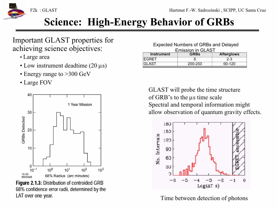
Science: High-Energy Behavior of GRBsImportant GLAST properties for achieving science objectives:
• Large area• Low instrument deadtime (20 µs)• Energy range to >300 GeV• Large FOV
Expected Numbers of GRBs and Delayed Emission in GLAST
GLAST will probe the time structure of GRB’s to the µs time scaleSpectral and temporal information might allow observation of quantum gravity effects.
Time between detection of photons

F2k : GLAST Hartmut F.-W. Sadrozinski , SCIPP, UC Santa Cruz
Science: Acceleration in AGN, Pulsars, & SNRsMulti-wavelength Observations are crucial for the understanding of Pulsars and AGN’s. Flares are largest at high energy.
Overlap of GLAST with ACT’s provides Needed energy calibration.
Crab
Mk 501
Synchrotron Radiation Inverse Compton
Flares

F2k : GLAST Hartmut F.-W. Sadrozinski , SCIPP, UC Santa Cruz
Instrument Performance
(Single Source F.o.M ~ Aeff /[σ(68%)]2)
FOV: 2.4 srSRD: 2.0 sr

F2k : GLAST Hartmut F.-W. Sadrozinski , SCIPP, UC Santa Cruz
Optimization of Converter Thickness t
0
500
1000
1500
2000
2500
0 5 10 15
Effective Area vs. Conversion Plane
Graded Converter (2.5%, 25%)Uniform Converter (3.5%)
x-y Plane
0.01
0.1
1
10
0.01 0.1 1 10 100
Gamma Angular Resolution PSF(68)
68% Front68% Back
Gamma Energy [GeV]
Aeff ~ t
PSF(68) ~ √t
For Background limited Sources:(Significance) = Aeff / PSF(68) 2
is independent of Converter Thickness
For High Latitude Sources:Number of detected gamma’s count.
0.9038%26%4Back
0.3938%3.8%12Front
PSF(68)@1GeV
[o]
γConversion
X0 per Layer
# of Layers

F2k : GLAST Hartmut F.-W. Sadrozinski , SCIPP, UC Santa Cruz
Overview of TKR Baseline Design
• 16 towers, each with 37 cm × 37 cm of Si (78m2 in all)
• 18 x,y planes per tower– 19 “tray” structures
• 12 with 2.5% Pb on bottom• 4 with 25% Pb on bottom• 2 with no converter
– Every other tray rotated by 90°, so each Pb foil is followed immediately by an x,yplane
• 2mm gap between x and y• Electronics on the sides of trays
– Minimize gap between towers– 9 readout modules on each of 4 sides
• Trays stack and align at their corners• The bottom tray has a flange to mount on
the grid• Carbon-fiber walls provide stiffness and
the thermal pathway to the grid
One Tracker Tower Module
Electronics flex cables
Carbon thermal
panel
F2k : GLAST Hartmut F.-W. Sadrozinski , SCIPP, UC Santa Cruz
Silicon-Strip Detectors
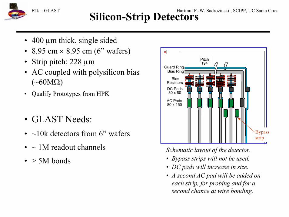
• 400 µm thick, single sided• 8.95 cm × 8.95 cm (6” wafers)• Strip pitch: 228 µm• AC coupled with polysilicon bias
(~60MΩ)• Qualify Prototypes from HPK
• GLAST Needs:• ~10k detectors from 6” wafers
• ~ 1M readout channels
• > 5M bonds
DC Pads80 x 80
AC Pads80 x 150
BiasResistors
Pads for BypassAl Traces80x150
Guard RingBias Ring
Pitch194
Bypass strip
Schematic layout of the detector. • Bypass strips will not be used.• DC pads will increase in size.• A second AC pad will be added on
each strip, for probing and for a second chance at wire bonding.

F2k : GLAST Hartmut F.-W. Sadrozinski , SCIPP, UC Santa CruzTracker of the Beam Test Engineering Module
End of one readout hybrid.
BTEM Tracker Module with side panels removed.
Single BTEM Tray
The BTEM Tracker, (~1/16 of the flight instrument) for the SLAC test beam (11/99 – 1/00)
- 2.7m2 silicon, ~500 detectors, 42k channels- all detectors are in 32 cm long ladders.
Si Detectors
HPK 296 (4”), 251 (6”)
Micron 5 (6” ) Leakage I: 300 nA/detector (HPK)
Bad strips: about 1 in 5000

F2k : GLAST Hartmut F.-W. Sadrozinski , SCIPP, UC Santa Cruz
Assembly of BTEM Tracker at SCIPP
4 trays, 10 eyes & 10 hands
17 trays!
2 delicate hands
2 trays and 2 observers
All done and all smiles.

F2k : GLAST Hartmut F.-W. Sadrozinski , SCIPP, UC Santa Cruz
Challenge #1 : Space Environment and Launch
BTEM TKR tray undergoing random vibration testing at GSFC.
Vibration Testing of a live tray up to 14g.Leakage current before and after shaking identical
Space Qualification:Assembly Methods
MaterialsTests
Aluminum and carbon-fiber mechanical model
of 10 stacked tracker trays, used by Hytec,
Inc. to validate the design in vibration tests.
FEM analysis of (a) TKR tray deflections and (b) of a complete TKR module. Fundamental frequencies are above 550 Hz for the tray and 300 Hz for the module, clamped only at its base.

F2k : GLAST Hartmut F.-W. Sadrozinski , SCIPP, UC Santa Cruz
Challenge #2: On Board Cosmic Ray Rejection
Diffuse High Latitude gamma-ray flux
C.R. Rejection needed 105 : 1 segmented ACD segmented CAL segmented TRK
Radiation Levels: 1krad in a 5year missionIssue: SEE from Heavy Ions (SEU & Latch-up)See below
LVL1 : 5kHzDownlink: 30Hz

F2k : GLAST Hartmut F.-W. Sadrozinski , SCIPP, UC Santa Cruz
Challenge # 3: 1M channels, 250W Power See Takanobu Handa’s Poster
Boss for mechanical and thermal attachment to the wall.
28 Amplifier chips
TermResis4 layers of 1/2 oz coppTEM
needs shielding around cable.
Digital Analog
Cross-over into the side arms
Bias + Analog 3.3VAnalog GroundAnalog 1.5V
Digital 3.3VDigital GroundLVDS Signals
Kapton Cable down the Tower Walls
Redundant, ultra-low power, low-noise FEE
Hybrid:
Electrical & mechanical Challenge
Digital readout controller chip at each end
25-pin Nanonics connector

F2k : GLAST Hartmut F.-W. Sadrozinski , SCIPP, UC Santa Cruz
0 200 400 600 800 1000 1200 1400
10-5
Strip Number
Layer 6x
Occ
upan
cyChallenge #4: Tracker Noise and Efficiency
• Noise occupancy determines the noise rate of the LVL1 trigger, a coincidence of 6 OR’dlayers.
• Noise RMS σ = 130 + 21*C/pF [e-] , τ =1.3µs• Hit efficiency was measured using single
electron tracks and cosmic muons.• The requirements were met: 99% efficiency
with <<10−4 noise occupancy.0 200 400 600 800 1000 1200 1400
Threshold (mV)
0.1
0.2
0.3
0.4
0.5
0.6
0.7
0.8
0.9
1.0
1.1
Effi
cien
cy
Layer 10 xLayer 10 y
1 2 3 4 5Detector Ladder
95
96
97
98
99
100
101
Hit
Effi
cien
cy
Layer 6xCosmic RaysElectron Beam
Noise occupancy and hit efficiency for Layer 6x, using in both cases a threshold of 170 mV. Nochannels were masked.
Hit efficiency versus threshold for 5 GeV positrons.
100,000 triggers

F2k : GLAST Hartmut F.-W. Sadrozinski , SCIPP, UC Santa Cruz
Space Environment: RadiationGLAST is in a Low-Earth Orbit (550km):
Shielding of Atmosphere and magnetic Field Avoid (most!) of the radiation belts
Orbit co-determined by Re-entry > 10 Years, < 30years.
USA on ARGOS
Radiation Belts: - High LatitudeSouth Atlantic Anomaly (SAA)-Trapped electrons and protons
responsible for Total Dosecause huge trigger rate(Detectors will be switched off)
Outside radiation Belts:Charged Cosmic Ray Background (p, e, heavy ions) Responsible for Single Event Effects (SEE)

F2k : GLAST Hartmut F.-W. Sadrozinski , SCIPP, UC Santa Cruz
Long-term Radiation Damage:
Entirely given by electron and proton flux trapped in the SAA
Extremely soft spectrum: Self shielding of Instrument:Blanket, ACD, walls: 2.50g/cm2
Cut-off at 80MeV protons
Radiation: Total Dose & Displacement
0
5
10
15
20
25
30
0 5 10 15 20 25 30
GLAST Silicon Tracker End-of-Mission Signal-to-Noise
S/N E-o-M 1x
S/N E-o-M 5x
Temperature [deg C]
Total Dose 1kRad (5 yrs) -NASA safety factor: 5x-Leakage current increase 50% surface, 50% bulk(same temperature dependence).
Increase in shot noise due to radiation constrains operating temperature to below 25oC.
1
10
100
1000
10000
100000
0.01 0.1 1 10
ElectronsBremsstrahlungProtonsTotal
Full dose - Spherical shield550 km 28° circular orbit
5-year mission - Solar Minimum
Depth (g/cm2 Al)

F2k : GLAST Hartmut F.-W. Sadrozinski , SCIPP, UC Santa Cruz
Heavy Ion Radiation: Temporal Effects (SEE)Linear Energy Transfer LET governs Single Event Effects: SEU, SEL, Punch Through LET is dE/dx: LET (Min ion) ≈ 1.3*10-3 MeV/(mg/cm2), LET ~ Z2 : LET (Fe) ≈ 1-2 MeV/(mg/cm2).
Fe
GLAST IRD
Update from AMS

F2k : GLAST Hartmut F.-W. Sadrozinski , SCIPP, UC Santa Cruz
Heavy Ion Radiation: Single Event Upset
Credit: http://www.aero.org

F2k : GLAST Hartmut F.-W. Sadrozinski , SCIPP, UC Santa Cruz
Silicon Detectors in High Radiation Fields
Past Problems— beam loss LEP (CERN) ALEPH/Babar detector shorted out due
to beam loss; unexpected large voltageacross coupling capacitance
Future (?) Problems—High Luminosity colliders (BaBar, ATLAS)
prepare for large ionization in Siliconmicrostrip detectors either from beamloss or minimum bias particles
Detectors in Space(?) (GLAST)
heavy ions (Fe) will have ionization power of 1000’s of minimum ionizing particles
• Beam loss is measured in fluence [MIPs / cm2] or total absorbed dose(Si) [Rad]
• In 300µm thickness 1 Rad = 106 MIPs/ cm2
• Detectors are designed for MIP signal: 1MIP = 4fC = 24,000 electron-holes pairs
• Detectors might not be optimized for high radiation field

F2k : GLAST Hartmut F.-W. Sadrozinski , SCIPP, UC Santa Cruz
GLAST Challenges from Radiation
Total Dose and Displacement requirements are modest, but shot noise increase is noticeable due to detector length and long shaping time.Limit on operating temperature.
SEE is more demanding and need careful testing. Tests with lasers and heavy ion beams needed to make sure that SEE is not a problem.
Choice of CMOS technology helps: either SoI or HP 0.5um are attractive.SEU hardened design and SEL resistant design are fallback.
SEU: Frequent refreshing of registers advisable.
Detectors are susceptible to breakdown for large LET.Specify coupling capacitors for full operating voltage.

F2k : GLAST Hartmut F.-W. Sadrozinski , SCIPP, UC Santa Cruz
GLAST Development Process and Status
Date Activity Program
93-98 Conceptual study NASA SR&DDetector R&D DoE R&D
(Beam Test 1998)98 DoE Review SAGENAP
Endorsement98-00 Technology NASA ATD
Development (BTEMFull Size ModulesManufact. ProcessASIC’s, DAQ)
Fall 99 Instrument Proposal NASA AO GLAST Base LIne(Si TKR, CsI CAL, ACD)Endorsements, MoA
Feb 25, 00 Decision on AO GLAST-LAT selected
Sept 2005 Launch on Delta 2
What New Worlds are we going to see?