GLAST Large Area Telescope · GLAST Large Area Telescope: Tracker Subsystem ... – An IDD draft is...
20
GLAST LAT Project December 10, 2003 LAT Face-to-Face Management Meeting Tracker, WBS 4.1.4 1 GLAST Large Area Telescope: GLAST Large Area Telescope: Tracker Subsystem WBS 4.1.4 December 10 Management Meeting Robert Johnson Santa Cruz Institute for Particle Physics University of California at Santa Cruz Tracker Subsystem Manager [email protected] Gamma Gamma - - ray Large ray Large Area Space Area Space Telescope Telescope
Transcript of GLAST Large Area Telescope · GLAST Large Area Telescope: Tracker Subsystem ... – An IDD draft is...

GLAST LAT Project December 10, 2003
LAT Face-to-Face Management Meeting Tracker, WBS 4.1.4 1
GLAST Large Area Telescope:GLAST Large Area Telescope:
Tracker SubsystemWBS 4.1.4
December 10 Management Meeting
Robert JohnsonSanta Cruz Institute for Particle PhysicsUniversity of California at Santa CruzTracker Subsystem Manager
GammaGamma--ray Large ray Large Area Space Area Space TelescopeTelescope

GLAST LAT Project December 10, 2003
LAT Face-to-Face Management Meeting Tracker, WBS 4.1.4 2
OutlineOutline
• Tracker Milestones• Near Term Schedule Issues• Interdependencies• Open flight design issues; status; closure plan• Issues, concerns, suggestions, risks

GLAST LAT Project December 10, 2003
LAT Face-to-Face Management Meeting Tracker, WBS 4.1.4 3
Milestone DescriptionOriginal
DateCurrent
Date Major Requirements to Achieve Milestone NotesStatic Test Bottom Tray 07/25/03 11/26/03 CompletedVibration and T/V Test of EM Tower 08/01/03 ? Complete testing of Plyform sidewall coupons,
including fastener pullout and thermal conduction. Complete engineering of the new flexure-grid joint and implement on the existing tower. Complete TRR for the T/V test. Finish and release T/V test documents. Complete fixtures for T/V testing.
Issues with understanding the Plyform coupon test data still need to be closed to everybody's satisfaction. Plyform coupons with inserts and coupons for thermal conduction still need to be tested. Schedule is uncertain pending closure on the fix to the flexure-grid joint issues.
AV: Delv of TKR EM to SLAC I&T/MGSE
08/22/03 ? Complete vibration and T/V testing. Ship to SLAC.
Deliver 36 MCMs and 8 flex cables to electronics
09/15/03 12/20/03 We have provided the MCM and burn-in cable parts to the electronics group. We are helping them with testing and debugging, but it is their schedule now to complete these parts.
Most of the MCMs, as well as the cable hardware were delivered to SLAC by UCSC. Several MCMs are still being debugged and reworked at UCSC.
Composite tray panels assembled for tower A
09/30/03 01/31/04 Bias circuits. Drawing review & release. Closure of PRR action items.
Bias circuits are still late and have delayed the start of production of non-flight panels. Flight panel production cannot start until a big list of QA issues (mostly with documentation) is closed.
Top and Bottom tray panel assembled for tower A
01/31/04 01/31/04 Drawing completion and release. Closure of flexure-grid interface issues. Procure flexures, corner brackets, thermal straps. Procure bottom-tray closeouts from COI. Complete new assembly fixtures.
In progress. Quotes for titanium parts are coming in.
Start flex-circuit cable production 09/30/03 12/20/03 Complete and review the detailed layout. PRR Design review completed. Need to complete drawings and hold PRR still. SOW still not released. Detailed drawings should be completed by the end of this week.
Start flight sidewall production 10/15/03 ? Successful completion of EM sidewalls and coupon tests. Completion of EM T/V testing. Order material in advance.
EM sidewall production is looking good at this point.
Complete the MCM preproduction run
12/20/03 12/20/03 In progress The preproduction is progressing reasonably well. The first small lot of completed boards was received 12/5/03.
Completion of functional trays for a new mini-tower and T/V testing.
01/31/04 01/31/04 Deliver 15 good MCMs to Italy. Get panel production going at Plyform.
These will have to be built with GTRC-V6 chips.
Deliver 1st lot of flight MCMs to Italy 10/29/03 03/15/04 Completion, burn-in, and test of the preproduction lot. Completion of the PRR. New GTRC chips.
The date is based on reception of V7 GTRC chips at the end of January.
Begin Test of completed trays for tower A
12/18/03 New "mini-tower" test. Vibration and T/V testing of some flight-like trays.
Complete Assembly of tower A 02/03/04 Tower assembly procedures; PRR; fixtures
Deliver Towers A/B to I&T 04/19/04 Environmental tests. Shipping containers
Trac
ker M
ilest
ones
Trac
ker M
ilest
ones

GLAST LAT Project December 10, 2003
LAT Face-to-Face Management Meeting Tracker, WBS 4.1.4 4
InterdependenciesInterdependencies
• Delivery of MCMs and cables to Electronics– Presently working at UCSC on debugging the last few MCMs of >36.– Burn-in cables have been delivered for interim work, until full-size flight
cables have been made.• Tracker-Grid Interface
– An IDD draft is out for review. • Tracker has issues with the height of the keep-out zones (cable stick
out the top of the Tracker).• Work in progress on the flexure-Grid interface.
– The vibration test problem has provoked a good team effort with mechanical systems to finalize the mechanical interface.
– Flex cable issues appear to be resolved. A paper fit check is being done this week, and a quick turn of mini-tower cables will be made. Release of the IDD is a prerequisite for manufacture of flight cables, however.
• Delivery of the EM tower to I&T– This is unfortunately delayed along with the EM environmental tests.

GLAST LAT Project December 10, 2003
LAT Face-to-Face Management Meeting Tracker, WBS 4.1.4 5
Open Design Issues Open Design Issues –– Flexure/Grid IFFlexure/Grid IF
• A series of engineering working meetings was held the last week– Torque loss in the corner flexures was understood qualitatively:
• The torque spec was low, and no locking feature was used.• The design relied upon friction to prevent movement by up to 4
mils within the tolerance between flexure and shoulder bolt, which could have started the loss of preload.
• Without tight support of the shoulder in the aluminum Grid, there was a potential for excessive bending stress on the bolt, which could have released the preload.
– Resolution:• Revise the design to ensure that the joint really behaves as a
shear pin, as it was modeled, with no reliance on friction to hold the shear.
• Avoid high tolerance requirements for the Grid and flexure machining, but also avoid preloading stress back into the bottom tray.
• Introduce a locking feature for the bolts.

GLAST LAT Project December 10, 2003
LAT Face-to-Face Management Meeting Tracker, WBS 4.1.4 6
Open Design Issues Open Design Issues –– Flexure/Grid IFFlexure/Grid IF– SLAC concept (see drawings on the next page)
• Corner flexures: conical bushing self centers in the flexure – Requires good precision on those 4 holes, matching TKR & Grid,
to avoid preloading stress into the bottom tray.– The bushing will fit tight into the flexure and Grid to act as a shear
pin. It will be easy to get the bolt started in the threads.• Side flexures: use an epoxy bushing (à la the Cal) to hold the
shear load with essentially no alignment requirement.– The load on each side flexure is much less than on each corner
flexure, and each side flexure has two bolts.– The side flexures did not lose their torque (except a slight loss in
two bolts) even at the maximum vibration load and even with the connections at the corners lost.
– Using the epoxy bushings reduces the geometric overconstraint from 12 holes (4 of which are slotted) down to just 4 holes.
– The side flexure drawing will need revision, to make the hole larger and to implement epoxy injection channels.

GLAST LAT Project December 10, 2003
LAT Face-to-Face Management Meeting Tracker, WBS 4.1.4 7
CornerCorner--FlexureFlexure--Grid AttachmentGrid Attachment
Grid
TKR Flexure
Shoulder Bolt
Collar/Pin with conical head(pressed in)
Concept under study at SLAC, down-selected from 4 different proposals.
Martin’s first cut at the dimensions:
Steel conical bushing self centers in the flexure and carries the shear load, with a tight fit in the Grid. The bolt just holds it in place.

GLAST LAT Project December 10, 2003
LAT Face-to-Face Management Meeting Tracker, WBS 4.1.4 8
CornerCorner--FlexureFlexure--Grid AttachmentGrid Attachment
GridFlexure
Proposed Bracket
Sandro has proposed an extra bracket to be added to fix the flexure to the grid. Some issues to consider with this:
•Clearance inside the grid (e.g. calorimeter & TKR cables)•Precision location of the 4 new holes (a friction mount won’t beaccepted, so at least some of those holes will need shear pins).

GLAST LAT Project December 10, 2003
LAT Face-to-Face Management Meeting Tracker, WBS 4.1.4 9
Open Design Issues Open Design Issues –– Flexure/Grid IFFlexure/Grid IF
• MRB by Friday or Monday.• Complete all design work before the holiday.
– CAD design of interface by Dec 11.– Incorporate into the Tracker flight drawings and IDD by Dec 15.
• Retrofit the existing bottom-tray flexures and the vibration fixture in early January.
• Get back on the vibration tester at Alenia as early as January 19.• The thermal vacuum test should follow the vibration, as we cannot
run the vibration test with the thermocouples installed between trays.

GLAST LAT Project December 10, 2003
LAT Face-to-Face Management Meeting Tracker, WBS 4.1.4 10
Open Design Issues Open Design Issues –– Sidewall ScrewsSidewall Screws
When assembling the tower, the screw torque was limited to 40 N-cm, to avoid possible damage to the carbon-fiber as the wall pulls into the gap between the CC and insert surfaces.
– None of these screws loosened in the test.– We are interested in having higher margin,
however.
sidewall
screwAl insert
CC closeout
Example of a hole in the sidewall, opposite the countersink, before torque is applied.
After 80 N-cm of torque there is a clear impression of the head of the screw.
Gap from tolerance stack-up and bondline of insert head.

GLAST LAT Project December 10, 2003
LAT Face-to-Face Management Meeting Tracker, WBS 4.1.4 11
Open Design Issues Open Design Issues –– Sidewall ScrewsSidewall Screws
• Options considered:– Redesign inserts and tooling to pull the inserts flush.
• This is a big change in process and tooling.• Serious schedule issue to go back to the drawing board when
the tray production should be starting NOW. We rule this out.– Change to larger screw heads with 120 degree countersink.
• Custom screws, but we already have some on order.• We are setting up a test with these screws and actual sidewall
material, to be completed before the holiday.– Install shim washers of various thicknesses during assembly.
• Tedious, but would certainly take care of the problem.– Put flush aluminum inserts into all of the sidewall holes.
• This could be the most solid design, but may be expensive.• Other possible issues have not yet been thought through.
Flush Insert ConceptOnly 1.5 mm!
GLAST LAT Project December 10, 2003
LAT Face-to-Face Management Meeting Tracker, WBS 4.1.4 12
Open Design IssuesOpen Design Issues
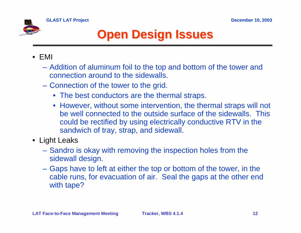
• EMI– Addition of aluminum foil to the top and bottom of the tower and
connection around to the sidewalls.– Connection of the tower to the grid.
• The best conductors are the thermal straps.• However, without some intervention, the thermal straps will not
be well connected to the outside surface of the sidewalls. Thiscould be rectified by using electrically conductive RTV in the sandwich of tray, strap, and sidewall.
• Light Leaks– Sandro is okay with removing the inspection holes from the
sidewall design.– Gaps have to left at either the top or bottom of the tower, in the
cable runs, for evacuation of air. Seal the gaps at the other end with tape?

GLAST LAT Project December 10, 2003
LAT Face-to-Face Management Meeting Tracker, WBS 4.1.4 13
Issues and ConcernsIssues and Concerns
• MCM, attachment of flex-circuit pitch adapter to the PWB– I showed the status of this last month. Since then
• The tooling and processes were tweaked.• Inspections were defined.• Teledyne production workers have gained experience.
– Machining of the PWB and the following inspections at SLAC are meeting our straightness and flatness requirements.
– The gluing results from Teledyne are probably reaching as good as possible with this process and tooling method.
– Two recent Teledyne samples will go back to Pisa with Ronaldo for evaluation.
– In parallel, G&A in Italy has been making progress on an alternative gluing process for the pitch adapter.

GLAST LAT Project December 10, 2003
LAT Face-to-Face Management Meeting Tracker, WBS 4.1.4 14
Issues and ConcernsIssues and Concerns
• MCM Burn-In– We are starting a test of the thermal-cycle and burn-in procedure
this week, on the first preproduction MCMs.– However, we still don’t have input from the project on burn-in
requirements. The MCM cannot operate above 85C or else the polyswitches will start to open.
• Omnetics Nano-Connectors– Somehow the design got “improved” with a longer jack screw that
engages long before the connector pins engage. This results in damaged connectors. The pins must start to engage before the screw. This will be fixed.
– The connectors are fragile, such that the metal shell too easilybreaks loose from the plastic insert.• This issue will be pursued with Omnetics (bonding procedure).• We are investigating our mounting schemes on cables and
MCMs to add strength (bonding or fastening both metal shell and plastic to the cable and MCM; potting of the solder pins).

GLAST LAT Project December 10, 2003
LAT Face-to-Face Management Meeting Tracker, WBS 4.1.4 15
Issues and ConcernsIssues and Concerns
Drawing Number
Drawing Name Rel Call
Orig Rel
LAT-DS-00049-03 Face Sheet Top (Mid Tray) 20-Nov 3/29/2002LAT-DS-00092-06 MCM Closeout Wall 20-Nov 9/12/2003LAT-DS-00093-05 Structural Closeout Wall 20-Nov 9/12/2003LAT-DS-00094-03 Closeout Inserts 20-Nov 7/15/2002LAT-DS-00139-03 MCM Closeout Wall Assembly 20-Nov 7/15/2002LAT-DS-00140-03 Structural Closeout Wall Assembly 20-Nov 7/15/2002LAT-DS-00148-03 Mid-Tray Composite Panel Assembly 20-Nov 5/17/2002LAT-DS-00417-03 Side Flexure 5-NovLAT-DS-00422-03 Corner Flexure 5-NovLAT-DS-00596-03 Face Sheet Bottom (Mid Tray) 20-Nov 3/29/2002LAT-DS-00617-03 Heavy Tray Tray Face Sheet Top 5-Nov 3/29/2002LAT-DS-00618-03 Heavy Tray Tray Face Sheet Bottom 5-Nov 3/29/2002LAT-DS-00718-03 3 mm Closeout Insert (7/5/02) 20-Nov 7/15/2002LAT-DS-00792-04 LAT TKR Heavy Converter Tray 18% Converter 5-NovLAT-DS-00800-01 Bottom MCM Closeout Wall 12-NovLAT-DS-00801-01 Bottom Structural Closeout Wall 12-NovLAT-DS-01803-02 Bottom Tray Corner Bracket LH 5-NovLAT-DS-01903-01 Bottom Tray Face Sheet Top 5-NovLAT-DS-01904-01 Bottom Tray Face Sheet Bottom 5-NovLAT-DS-01905-01 Bottom Tray M4X0.7X9 Insert 5-NovLAT-DS-01906-01 Bottom Tray M2.5X0.45X10.1 Insert 5-NovLAT-DS-01907-01 Bottom Tray M2.5X0.45X14 Insert 5-NovLAT-DS-01919-02 3MM Closeout Insert 5-NovLAT-DS-01921-02 Bottom Tray Corner Bracket H 5-NovLAT-DS-02112-01 TMCM Mounting Pin 20-NovLAT-DS-02206-01 Bottom Tray M4X0.7X14 Insert 5-NovLAT-DS-02609-01 Bottom Tray Structural Closeout Wall M55J Detail-A 11/21/03*LAT-DS-02610-01 Bottom Tray Structural Closeout Wall M55J Detail-B 11/21/03*LAT-DS-02616-01 Bottom Tray MCM Closeout Wall M55J Detail-A 11/21/03*LAT-DS-02617-01 Bottom Tray MCM Closeout Wall M55J Detail-B 11/21/03*
* Sent For Release - never distributed
Drawings Sent for Release in November• Drawing release– It appears that we need a full-
time person to keep track of the drawing and document release for the Tracker and push them through to completion.
– Need an expert drawing checker.– Most of the Tracker drawings are
stuck in the release process, especially with a QA hold on a huge set of them.
– We need to break loose those that are disconnected from all outstanding issues and move them forward.
– For example, there is no issue that I know of with the bottom-tray closeout design, but COI is on hold to build and machine those pending the drawing release.

GLAST LAT Project December 10, 2003
LAT Face-to-Face Management Meeting Tracker, WBS 4.1.4 16
Issues and ConcernsIssues and Concerns
• Tracker Drawing Status– 30 drawings put into the release system in November:
• 19 drawings were new releases.• 11 drawings were updates.
– 17 additional drawings were expected to be put into the release system in November but didn’t make it:• 8 drawings for flex cable assembly – new release.• 9 drawings for flex cable layout – second release.
– December projections:• 4 new drawings for sidewalls.• The 17 not put into the system in November.• Additional schematics and Gerber files.
– January projections:• Anything left not put into the system in December.

GLAST LAT Project December 10, 2003
LAT Face-to-Face Management Meeting Tracker, WBS 4.1.4 17
Issues and ConcernsIssues and Concerns
• Documentation– Plyform is ready to build mid trays as soon as they receive the
bias circuits. However, a myriad of QA documentation issues stand in the way of making flight trays (we can start some non-flight trays needed for a new mini-tower and T/V testing).
– Communication of documentation requirements seems to need improvement, to come to a common understand in U.S. and Italy.
– Manpower appears to be short to respond to all of the QA actionsin a timely manner and to complete the documentation for all processes.
GLAST LAT Project December 10, 2003
LAT Face-to-Face Management Meeting Tracker, WBS 4.1.4 18
Issues and ConcernsIssues and Concerns
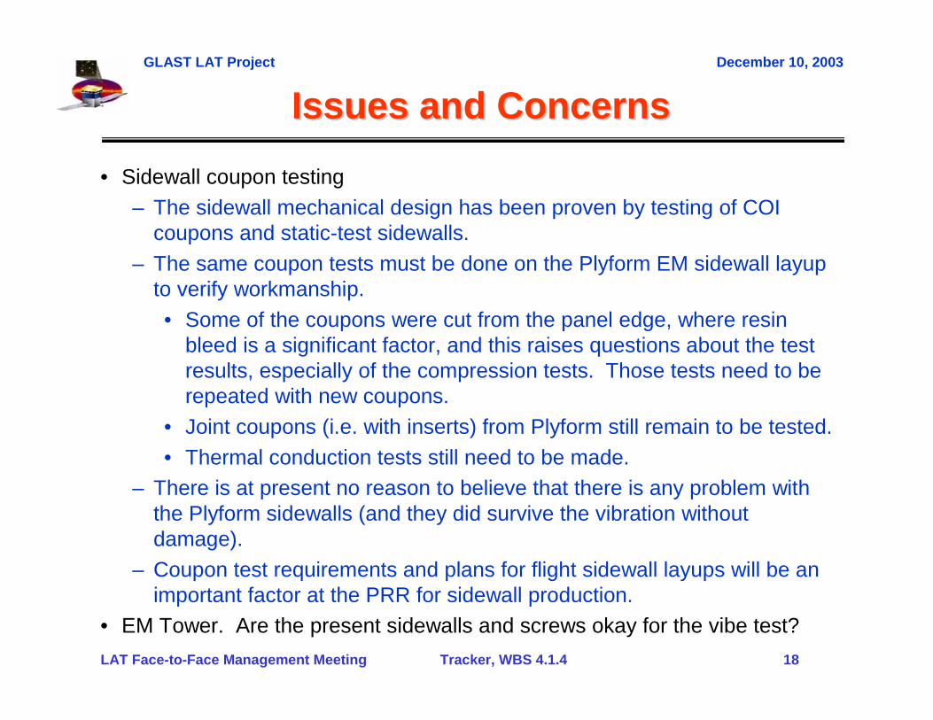
• Sidewall coupon testing– The sidewall mechanical design has been proven by testing of COI
coupons and static-test sidewalls.– The same coupon tests must be done on the Plyform EM sidewall layup
to verify workmanship. • Some of the coupons were cut from the panel edge, where resin
bleed is a significant factor, and this raises questions about the test results, especially of the compression tests. Those tests need to be repeated with new coupons.
• Joint coupons (i.e. with inserts) from Plyform still remain to be tested.• Thermal conduction tests still need to be made.
– There is at present no reason to believe that there is any problem with the Plyform sidewalls (and they did survive the vibration without damage).
– Coupon test requirements and plans for flight sidewall layups will be an important factor at the PRR for sidewall production.
• EM Tower. Are the present sidewalls and screws okay for the vibe test?

GLAST LAT Project December 10, 2003
LAT Face-to-Face Management Meeting Tracker, WBS 4.1.4 19
Issues and ConcernsIssues and Concerns• Installation of cables into the Grid
– Tooling for bending the cables when they are already installed on the tower.
– Procedure for bonding the cables to the Grid chaseways.• RTV vs PSA.• Clamping methods and curing time in the case of RTV.
• Schedule Issues– There is a danger of the tray panels taking over the critical path from the
MCMs if we don’t get tray production started.• Drawings and documentation for the mid trays.• Drawings, documentation, parts, and tooling for bottom trays.
– The GTRC V7 is a week or two later than forecast last month.• Preproduction experience in the next few weeks will firm up all the
MCM schedule projections.– We need from Italy a schedule and plan for sidewall production.
• This must include a PRR.– Failure to complete the EM tests results in a continuing drain on
resources.
GLAST LAT Project December 10, 2003
LAT Face-to-Face Management Meeting Tracker, WBS 4.1.4 20
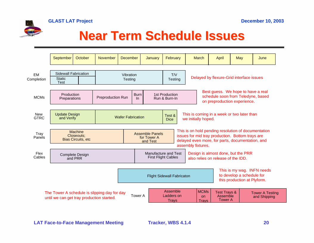
Near Term Schedule IssuesNear Term Schedule IssuesSeptember October November December January February March April May
EMCompletion
VibrationTesting
T/VTesting
Sidewall FabricationStaticTest
Preproduction RunBurn
InProduction
Preparations1st ProductionRun & Burn-InMCMs
TrayPanels
MachineCloseouts;
Bias Circuits, etcAssemble Panels
for Tower Aand Test
FlexCables
Complete Designand PRR
Manufacture and TestFirst Flight Cables
Update Designand Verify
New GTRC Wafer Fabrication Test &
Dice
Test Trays &AssembleTower A
AssembleLadders on
Trays
MCMson
TraysTower A
Tower A Testingand Shipping
June
Flight Sidewall Fabricaton
Delayed by flexure-Grid interface issues
This is on hold pending resolution of documentationissues for mid tray production. Bottom trays aredelayed even more, for parts, documentation, andassembly fixtures.
The Tower A schedule is slipping day for dayuntil we can get tray production started.
This is coming in a week or two later thanwe initially hoped.
Best guess. We hope to have a realschedule soon from Teledyne, basedon preproduction experience.
This is my wag. INFN needsto develop a schedule forthis production at Plyform.
Design is almost done, but the PRRalso relies on release of the IDD.