Gilbarco dispensers interface converter Gilbarco dispenser connection scheme Connection through...
21
TECHNICAL GUIDE Review date: 03 May 2013 Revision number: 1.03 PCB board revision: GILB-V2 TECHNOTRADE LTD Gilbarco dispensers interface converter (2-wire current loop to RS-485/RS-232 and backwards)
Transcript of Gilbarco dispensers interface converter Gilbarco dispenser connection scheme Connection through...

TECHNICAL GUIDE Review date: 03 May 2013
Revision number: 1.03
PCB board revision: GILB-V2
TECHNOTRADE LTD
Gilbarco dispensers interface converter
(2-wire current loop to RS-485/RS-232 and backwards)

GILBARCO DISPENSERS INTERFACE CONVERTER TECHNICAL GUIDE Revision number: 1.03, PCB board revision: GILB-V2 Review date: 03 May 2013
www.technotrade.ua page 2 from 21
CONTENT
REVISION HISTORY .......................................................................................................................................... 3
PURPOSE OF THE DOCUMENT ......................................................................................................................... 4
APPOINTMENT ................................................................................................................................................ 5
TECHNICAL SPECIFICATIONS ............................................................................................................................ 6
PCB BOARD CONNECTORS OVERVIEW ............................................................................................................. 7
CONNECTION SCHEME TO PTS CONTROLLER ................................................................................................... 8
CONNECTION SCHEME TO PC COM-PORT ........................................................................................................ 9
EXAMPLES OF FUEL DISPENSERS CONNECTION SCHEMES .............................................................................. 10
Gilbarco dispenser connection scheme ...................................................................................................10
Wayne Dresser dispenser connection scheme (current loop interface) ...................................................12
Batchen Email dispenser connection scheme ..........................................................................................13
PETPOSAN-S4 / MEKSAN-S4 / EUROPUMP-S4 dispensers connection scheme .........................................14
PETPOSAN-Beta / EUROPUMP-Beta dispensers connection scheme ........................................................15
EuroPump dispenser connection scheme ................................................................................................16
Mekser dispenser connection scheme.....................................................................................................17
PCB MOUNTING BOARD ................................................................................................................................ 18
CABLINGS ...................................................................................................................................................... 19

GILBARCO DISPENSERS INTERFACE CONVERTER TECHNICAL GUIDE Revision number: 1.03, PCB board revision: GILB-V2 Review date: 03 May 2013
www.technotrade.ua page 3 from 21
REVISION HISTORY
REV DATE BY SECTION DESCRIPTION
1.03 03.05.2013 EV Connection schemes updated Updated schemes of fuel dispensers connection
1.02 06.01.2013 EV All Sections review for PCB revision GILB-V2
1.01 03.08.2012 EV All First release

GILBARCO DISPENSERS INTERFACE CONVERTER TECHNICAL GUIDE Revision number: 1.03, PCB board revision: GILB-V2 Review date: 03 May 2013
www.technotrade.ua page 4 from 21
PURPOSE OF THE DOCUMENT
This Technical Guide is intended for studying of Gilbarco dispensers interface converter. It contains basic
information regarding its board interfaces and connectors, configuration and adjustments, connection to
fuel dispensers and external control systems (POS systems, cash registers, OPT terminals, etc), cablings.
Information regarding connection to specific models of fuel dispensers and correspondent configuration of
the Gilbarco dispensers interface converter can be received upon request to TECHNOTRADE LTD company.
Due to a reason that Gilbarco dispensers interface converter is constantly being developed in direction of
improvements of its possibilities, changes are possible in final version, which are not described in given
Technical Guide.
During the system development process given Technical Guide will be also expanded and updated and new
chapters will be added. Latest version of this Technical Guide can be downloaded from the Gilbarco
dispensers interface converter web-page: http://www.technotrade.ua/gilbarco_interface_converter.html.
TECHNOTRADE LTD hereby permits reproduction of this document as may be required by any of the
customers or OEMs wishing to use it.
This document has been carefully prepared and is believed to be accurate. However TECHNOTRADE LTD, its
employees and its agents do not assume responsibility for its use either directly or indirectly.
TECHNOTRADE LTD shall not be liable for technical or editorial errors or omissions which may appear in this
document. TECHNOTRADE LTD reserves a right to make changes to this document at any time without
notice. Prospective users of this document should contact TECHNOTRADE LTD at the time they wish to use
Gilbarco dispensers interface converter together with their products to become aware of any updates that
may apply.
In case if you find any mistakes, omissions in this document or have any suggestions on improvements to
this document, please feel free to e-mail them to our support mailbox: [email protected]. We
will be grateful to you for this valuable information.
All technical questions regarding the Gilbarco dispensers interface converter are welcome to be asked on
support mailbox: [email protected]. Our support team will be glad to help you.
Also you can call to us or visit us on:
TECHNOTRADE LTD
Ukraine, 04114 Kiev, Polupanova str. 10, office 1
Tel: +38-044-502-46-55, +38-044-502-46-77
Web: www.technotrade.ua
Mail: [email protected]

GILBARCO DISPENSERS INTERFACE CONVERTER TECHNICAL GUIDE Revision number: 1.03, PCB board revision: GILB-V2 Review date: 03 May 2013
www.technotrade.ua page 5 from 21
APPOINTMENT
Gilbarco dispenser interface converter (2-wire current loop to RS-485/RS-232 and backwards) is intended
for communication with fuel dispensers, which use 2-wire current loop interface, through interfaces:
- RS-232,
- RS-485 (half-duplex),
- RS-485 (full-duplex),
- RS-485 (half-duplex with control over RTS) – used for PTS controller over fuel dispensers and ATG
systems for petrol stations (http://www.technotrade.ua/fuel_pump_controller.html).
Although the interface converter is called ‘Gilbarco dispenser interface converter‘ cause mostly Gilbarco
dispensers use 2-wire current loop interface, this interface converter can also be applied for
communication with other brands of fuel dispensers, which use 2-wire current loop for communication
with control systems.
Some of fuel dispenser brands, which use 2-wire current loop:
- Salzkotten
- Batchen Email
- Prowalco
- Wayne Dresser (USCL communication protocol)
- PetroTec
- EuroPump
- Mekser
- Meksan
- Petposan
- PEC (Gallagher Fuel Systems)
- Bennett
- Falcon LPG
- Greenfield

GILBARCO DISPENSERS INTERFACE CONVERTER TECHNICAL GUIDE Revision number: 1.03, PCB board revision: GILB-V2 Review date: 03 May 2013
www.technotrade.ua page 6 from 21
TECHNICAL SPECIFICATIONS
Specification
Power supply voltage +12 V DC, +5 V DC
Current consumption 200 mA max
Temperature range -40°C ÷ +80°C
Weight 120 g
Dimensions 145 x100 x 20 mm
Technical characteristics
Current level in current loop interface
Adjustable using jumpers XP1, XP2, XP3, XP6, XP7, XP8, located on Gilbarco PCB board, selected values: 30 mA, 45 mA, 60 mA
Current loop generator Сurrent generator
Communication ports
PORT NAME INTERFACE PURPOSE
PC
PO
RT
PC PORT
(RS-232) RS-232 Selection of interface is made using jumpers XP9, XP10, XP11, located on Gilbarco PCB board. Interface RS-485 (half-duplex with control over RTS), which is marked as PTS on PCB board serves for connection with PTS controller over fuel dispensers and ATG systems for petrol stations (http://www.technotrade.ua/fuel_pump_controller.html)
PC PORT
(RS-485)
RS-485 (half-duplex),
RS-485 (full-duplex),
RS-485 (half-duplex with control over RTS)
PU
MP
PO
RT
Pump port 1
Optically isolated Gilbarco active current loop
Connection with Gilbarco fuel dispensers using 2 wires. One Gilbarco dispenser is to be connected to each of the pump ports.
Pump port 2
Pump port 3
Pump port 4
Pump port 5
Pump port 6

GILBARCO DISPENSERS INTERFACE CONVERTER TECHNICAL GUIDE Revision number: 1.03, PCB board revision: GILB-V2 Review date: 03 May 2013
www.technotrade.ua page 7 from 21
PCB BOARD CONNECTORS OVERVIEW
NOTE!
Jumpers XP9, XP10, XP11 serve for selection of interface:
- RS-232,
- RS-485 (half-duplex),
- RS-485 (full-duplex),
- RS-485 (half-duplex with control over RTS) – used for communication with PTS controller over fuel
dispensers and ATG systems for petrol stations.
Jumpers for selection of current level in each of the pump channels are adjusted in accordance with an
image located on PCB board, which indicates current level in pump channel in accordance with set jumpers.
Possible current levels:
- 20 mA,
- 40 mA,
- 60 mA.
In case if there is no jumper set current level in pump channel will equal 0 and pump channel will not
operate.

GILBARCO DISPENSERS INTERFACE CONVERTER TECHNICAL GUIDE Revision number: 1.03, PCB board revision: GILB-V2 Review date: 03 May 2013
www.technotrade.ua page 8 from 21
CONNECTION SCHEME TO PTS CONTROLLER
Information about PTS controller over fuel dispensers and ATG systems can be found on PTS controller
web-page: http://www.technotrade.ua/fuel_pump_controller.html.
Position of jumpers and state of LEDs on the interface converter board:
- Jumper XP9 should be in position 485
- Jumper XP10 should be in position PTS
- Jumper XP11 should be in position PTS
- LED HL4 indicating normal operation of firmware should be shining
- LEDs HL8, HL9 and HL10 should be shining, which indicate presence of 5 V DC and 12 V DC on the
board
- LEDs HL24 and HL25 should be blinking, which indicated communication with the PTS controller
- LED on pump channel, where the dispenser is connected (HL1 or HL2 or HL3 or HL5 or HL6 or HL7)
should be constantly shining at closing of the current loop interface, if the LED is not shining - then
current loop is not closed or connection is done incorrectly: '+' may by mistake be connected with '-' in
dispenser pumphead
- On pump channel, where dispenser is connected, jumpers for setting of current level in the channel
should be set (jumper XP1, XP2, XP3, XP6, XP7, XP8). If there is only 1 jumper – current in channel is 20
mA, 2 jumpers – 40 mA, 3 jumpers – 60 mA. If there are no jumpers set - no current in line.
Gilbarco fuel dispenser interface converter
Pump port (XP1):
pump channels 1, 2, 3
Pump port (XP2):
pump channels 4, 5, 6
+5 V
GND
GND
+12 V
Cable C012-1 (connector X1)
Connection through pump channel 1
of PTS controller (example)
Cab
le C
02
6
Pump port (XP2):
pump channel 1 (RS-485)
GILBARCO DISPENSERS INTERFACE CONVERTER TECHNICAL GUIDE Revision number: 1.03, PCB board revision: GILB-V2 Review date: 03 May 2013
www.technotrade.ua page 9 from 21
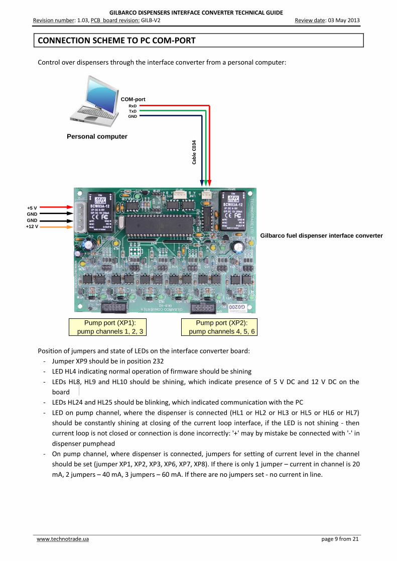
CONNECTION SCHEME TO PC COM-PORT
Control over dispensers through the interface converter from a personal computer:
Position of jumpers and state of LEDs on the interface converter board:
- Jumper XP9 should be in position 232
- LED HL4 indicating normal operation of firmware should be shining
- LEDs HL8, HL9 and HL10 should be shining, which indicate presence of 5 V DC and 12 V DC on the
board
- LEDs HL24 and HL25 should be blinking, which indicated communication with the PC
- LED on pump channel, where the dispenser is connected (HL1 or HL2 or HL3 or HL5 or HL6 or HL7)
should be constantly shining at closing of the current loop interface, if the LED is not shining - then
current loop is not closed or connection is done incorrectly: '+' may by mistake be connected with '-' in
dispenser pumphead
- On pump channel, where dispenser is connected, jumpers for setting of current level in the channel
should be set (jumper XP1, XP2, XP3, XP6, XP7, XP8). If there is only 1 jumper – current in channel is 20
mA, 2 jumpers – 40 mA, 3 jumpers – 60 mA. If there are no jumpers set - no current in line.
Pump port (XP1):
pump channels 1, 2, 3
Pump port (XP2):
pump channels 4, 5, 6
Cab
le C
03
4
RxD
TxD
GND
Personal computer
COM-port
+5 V
GND
GND
+12 V
Gilbarco fuel dispenser interface converter

GILBARCO DISPENSERS INTERFACE CONVERTER TECHNICAL GUIDE Revision number: 1.03, PCB board revision: GILB-V2 Review date: 03 May 2013
www.technotrade.ua page 10 from 21
EXAMPLES OF FUEL DISPENSERS CONNECTION SCHEMES
Gilbarco dispenser connection scheme
Gilbarco Encore 500 dispenser board
Cab
le C
02
7
Connection through first channel of
Gilbarco converter (example)
Gilbarco dispenser ASSY M06104A001 rev. B board
Cable C027
Connection through first channel of
Gilbarco converter (example)
Gilb
arc
o d
ispenser
board
Cable C027
Connection through first channel of
Gilbarco converter (example)

GILBARCO DISPENSERS INTERFACE CONVERTER TECHNICAL GUIDE Revision number: 1.03, PCB board revision: GILB-V2 Review date: 03 May 2013
www.technotrade.ua page 11 from 21
Cable C027
Connection through first channel of
Gilbarco converter (example)
Gilbarco Euroline dispenser board
Cable C027
Connection through first channel of
Gilbarco converter (example)
Gilbarco Highline / Dimension Assy dispenser board
Cable C027
Connection through first channel of
Gilbarco converter (example)
Gilbarco Endeavor dispenser board

GILBARCO DISPENSERS INTERFACE CONVERTER TECHNICAL GUIDE Revision number: 1.03, PCB board revision: GILB-V2 Review date: 03 May 2013
www.technotrade.ua page 12 from 21
Cable C027
Cable C027
Wayne Dresser dispenser connection scheme (current loop interface)
Cab
le C
02
7
Connection through first channel of
Gilbarco converter (example)
Wayne Dresser dispenser board
Connection through first channel of
Gilbarco converter (example)
Wayne Dresser dispenser board
Connection through first channel of
Gilbarco converter (example)
Wayne Dresser dispenser iGEM board

GILBARCO DISPENSERS INTERFACE CONVERTER TECHNICAL GUIDE Revision number: 1.03, PCB board revision: GILB-V2 Review date: 03 May 2013
www.technotrade.ua page 13 from 21
Batchen Email dispenser connection scheme
Cable C027
Connection through first channel of
Gilbarco converter (example)
Cable C027
Connection through first channel of
Gilbarco converter (example)
Batchen dispenser board
Batchen dispenser board

GILBARCO DISPENSERS INTERFACE CONVERTER TECHNICAL GUIDE Revision number: 1.03, PCB board revision: GILB-V2 Review date: 03 May 2013
www.technotrade.ua page 14 from 21
PETPOSAN-S4 / MEKSAN-S4 / EUROPUMP-S4 dispensers connection scheme
Cable C027
Connection through first channel of
Gilbarco converter (example)
S4 computer

GILBARCO DISPENSERS INTERFACE CONVERTER TECHNICAL GUIDE Revision number: 1.03, PCB board revision: GILB-V2 Review date: 03 May 2013
www.technotrade.ua page 15 from 21
PETPOSAN-Beta / EUROPUMP-Beta dispensers connection scheme
Cable C027
Connection through first channel of
Gilbarco converter (example)
Petposan-Beta CPU
IntBox

GILBARCO DISPENSERS INTERFACE CONVERTER TECHNICAL GUIDE Revision number: 1.03, PCB board revision: GILB-V2 Review date: 03 May 2013
www.technotrade.ua page 16 from 21
EuroPump dispenser connection scheme
Cable C027
Connection through first channel of
Gilbarco converter (example)
EuroPump dispenser board

GILBARCO DISPENSERS INTERFACE CONVERTER TECHNICAL GUIDE Revision number: 1.03, PCB board revision: GILB-V2 Review date: 03 May 2013
www.technotrade.ua page 17 from 21
Mekser dispenser connection scheme
Cable C027
Connection through first channel of
Gilbarco converter (example)
Mekser dispenser board

GILBARCO DISPENSERS INTERFACE CONVERTER TECHNICAL GUIDE Revision number: 1.03, PCB board revision: GILB-V2 Review date: 03 May 2013
www.technotrade.ua page 18 from 21
PCB MOUNTING BOARD

GILBARCO DISPENSERS INTERFACE CONVERTER TECHNICAL GUIDE Revision number: 1.03, PCB board revision: GILB-V2 Review date: 03 May 2013
www.technotrade.ua page 19 from 21
CABLINGS
Cab
le C
02
7
Cab
le C
02
7
Cab
le C
034
Cab
le C
026

GILBARCO DISPENSERS INTERFACE CONVERTER TECHNICAL GUIDE Revision number: 1.03, PCB board revision: GILB-V2 Review date: 03 May 2013
www.technotrade.ua page 20 from 21
CABLE C026
CABLE C027

GILBARCO DISPENSERS INTERFACE CONVERTER TECHNICAL GUIDE Revision number: 1.03, PCB board revision: GILB-V2 Review date: 03 May 2013
www.technotrade.ua page 21 from 21
CABLE C034