
GIFKINS DOVETAIL JIG - Classic Hand Tools Limited · INITIAL SET-UP OF JIG Follow steps 1 to 9...
25
INSTRUCTION MANUAL “Limited only by your imagination” GIFKINS DOVETAIL JIG
-
Upload
dinhkhuong -
Category
Documents
-
view
244 -
download
6
Transcript of GIFKINS DOVETAIL JIG - Classic Hand Tools Limited · INITIAL SET-UP OF JIG Follow steps 1 to 9...
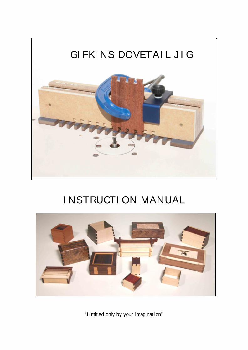
INSTRUCTION MANUAL
“Limited only by your imagination”
GIFKINS DOVETAIL JIG

TEMPLATE SPECIFICATIONS
All measurements are in millimetres – pin spacing is center to center. * By changing the procedure slightly, it is possible to go as thin as you like with any template – see note 27.
CUTTER SPECIFICATIONS
These drawings show the cutters ACTUAL SIZE. Please note: Before use, please check the collars on the shank of the router bits are tight, using the allan key provided. The straight cutter for the “H” templates is larger in diameter than the straight cutter for the “A” templates. If the cutters get mixed up, look at the length of the cutting tips:
“H” cutting tips are 10 mm long “A” cutting tips are 13 mm long “B” cutting tips are 22 mm long
These cutters are made specially for the Gifkins Dovetail Jig by Carb-I-Tool in Melbourne, and are available from either Gifkins Dovetail or Carb-I-Tool, or from our agents in the USA and England. The cutter product codes used above are the same as those used in the CARB-I–TOOL catalogue.
“H” SERIES “A” SERIES “B” SERIES Template H10 H20 A10 A20 B10 B20 Dovetail Cutter TGHD 12 TGAD 12 TGBD 16 ½ Straight Cutter TGHS 12 TGAS 12 TGBS 16 ½ Pin Size 6 6 10 11 17 17 Pin Spacing 18 26 20 28 38 48 Max Thickness 10 10 13 13 22 22 Min Thickness * 2 2 7 7 14 14 Max Width 300 300 310 305 310 310
“H” Series “A” Series “B” Series
11.1
10
TGHS 12
12.7
22
TGBS 16 ½
9.5
13
TGAS 12
1
6.2
10
TGHD 12
6.5°
9.5
13
TGAD 12
8°
15.9
22
TGBD 16 ½
8°
12.7 12.7
19.1
INITIAL SET-UP OF JIG
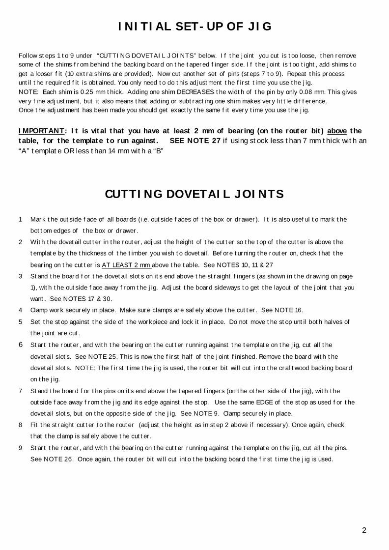
Follow steps 1 to 9 under “CUTTING DOVETAIL JOINTS” below. If the joint you cut is too loose, then remove some of the shims from behind the backing board on the tapered finger side. If the joint is too tight, add shims to get a looser fit (10 extra shims are provided). Now cut another set of pins (steps 7 to 9). Repeat this process until the required fit is obtained. You only need to do this adjustment the first time you use the jig. NOTE: Each shim is 0.25 mm thick. Adding one shim DECREASES the width of the pin by only 0.08 mm. This gives very fine adjustment, but it also means that adding or subtracting one shim makes very little difference. Once the adjustment has been made you should get exactly the same fit every time you use the jig. IMPORTANT: It is vital that you have at least 2 mm of bearing (on the router bit) above the table, for the template to run against. SEE NOTE 27 if using stock less than 7 mm thick with an “A” template OR less than 14 mm with a “B”
CUTTING DOVETAIL JOINTS
1 Mark the outside face of all boards (i.e. outside faces of the box or drawer). It is also useful to mark the bottom edges of the box or drawer.
2 With the dovetail cutter in the router, adjust the height of the cutter so the top of the cutter is above the template by the thickness of the timber you wish to dovetail. Before turning the router on, check that the
bearing on the cutter is AT LEAST 2 mm above the table. See NOTES 10, 11 & 27 3 Stand the board for the dovetail slots on its end above the straight fingers (as shown in the drawing on page
1), with the outside face away from the jig. Adjust the board sideways to get the layout of the joint that you want. See NOTES 17 & 30.
4 Clamp work securely in place. Make sure clamps are safely above the cutter. See NOTE 16.
5 Set the stop against the side of the workpiece and lock it in place. Do not move the stop until both halves of the joint are cut.
6 Start the router, and with the bearing on the cutter running against the template on the jig, cut all the
dovetail slots. See NOTE 25. This is now the first half of the joint finished. Remove the board with the dovetail slots. NOTE: The first time the jig is used, the router bit will cut into the craftwood backing board on the jig.
7 Stand the board for the pins on its end above the tapered fingers (on the other side of the jig), with the outside face away from the jig and its edge against the stop. Use the same EDGE of the stop as used for the dovetail slots, but on the opposite side of the jig. See NOTE 9. Clamp securely in place.
8 Fit the straight cutter to the router (adjust the height as in step 2 above if necessary). Once again, check that the clamp is safely above the cutter.
9 Start the router, and with the bearing on the cutter running against the template on the jig, cut all the pins. See NOTE 26. Once again, the router bit will cut into the backing board the first time the jig is used.
2

NOTES: (see page 20 for additional notes) 1 DOVETAILS are cut on the STRAIGHT fingers with a DOVETAIL cutter.
This side of the Jig is labelled DOVETAIL, for use with the DOVETAIL cutter.
2 PINS are cut on the TAPERED fingers with a STRAIGHT cutter. This side of the Jig is labelled STRAIGHT, for use with the STRAIGHT cutter.
3 BLUNT CUTTERS: If the cutters are blunt, not only will the quality of the cut be poor, but there is also a risk that excess chatter will cause the cutters to slowly vibrate out of the router. This will destroy the joint being cut and may lead to cutter breakage.
4 CLEAN TEMPLATE. It is important to keep the template free from any build-up of shavings or dust, as this could make the joint too tight. Clean all the fingers on the template regularly with a cloth or a nylon brush.
5 WORN COLLET or ADAPTER SLEEVE (especially when using a ¼” cutter in a ½” router). 80% of all cutter breakage is directly related to worn collets and adapter sleeves. If the shank of the cutter shows wear marks just below the top of the collet or sleeve, then the collet or sleeve needs replacing. This is much cheaper than replacing the bits! If the router is in good condition there should be NO wear marks on the shank of the router bit.
6 BEARINGS: The bearings on the cutters should be oiled regularly so that they always turn freely. If they are not free they will damage the template! Get in the habit of spinning them to make sure they run free, and oil them often. I use Singer household oil and apply a single drop after every half a dozen joints or so. After oiling, run the router for a few seconds to throw off any excess oil.
7 OLD TEMPLATES: This note only applies to people using the old model (red template) jig. The red templates use a template follower fitted to the router. The new BLUE templates use a top bearing on the router bit. The blue templates are a different profile to the red templates so they will not work with a template follower and the old cutters. Simmilarly, the red template will not work with the new cutters with a top bearing. It is not possible to fit bearings to the old cutters for use with the blue templates.
8 SPRINGS: The cutters for the “B” templates are now supplied with springs that fit on the shanks of the cutters, beneath the stop collar. These springs act as an insurance policy against the stop collar coming loose. Without the springs, if the collar did vibrate loose, the first you would know about it is when the router bit cut into the template, destroying the template. With the springs fitted this should not happen. Another benefit of the springs is that they hold the bit about 4 mm above the bottom of the chuck on most routers. This is generally recommended as the best position for the bit when tightening the bit in place, however it is usually dificult to do without three hands! The springs make it easy. The cutters for the “A” templates have a long stop collar which sits down against the collet on the router, so springs are not necessary. This stop collar also acts as a stiffener to reduce vibration and hence give a cleaner cut:
3
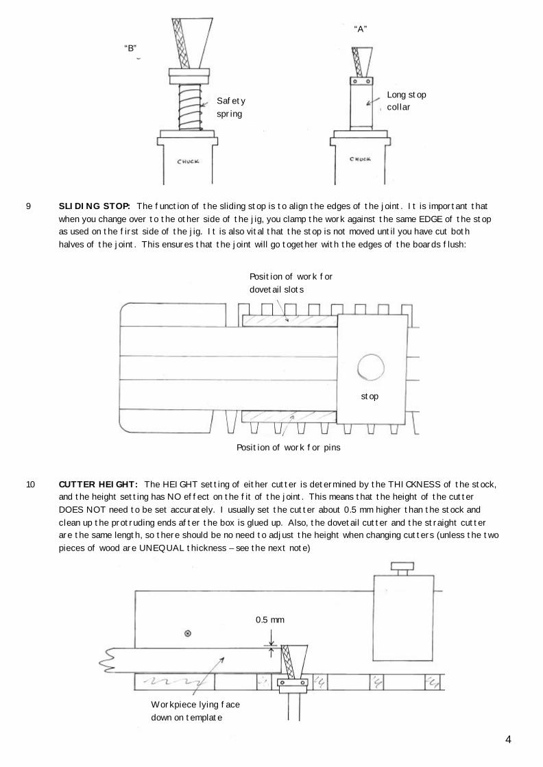
9 SLIDING STOP: The function of the sliding stop is to align the edges of the joint. It is important that when you change over to the other side of the jig, you clamp the work against the same EDGE of the stop as used on the first side of the jig. It is also vital that the stop is not moved until you have cut both halves of the joint. This ensures that the joint will go together with the edges of the boards flush:
10 CUTTER HEIGHT: The HEIGHT setting of either cutter is determined by the THICKNESS of the stock, and the height setting has NO effect on the fit of the joint. This means that the height of the cutter DOES NOT need to be set accurately. I usually set the cutter about 0.5 mm higher than the stock and clean up the protruding ends after the box is glued up. Also, the dovetail cutter and the straight cutter are the same length, so there should be no need to adjust the height when changing cutters (unless the two pieces of wood are UNEQUAL thickness – see the next note)
Safety spring
Long stop collar
“A”
“B”
Position of work for dovetail slots
Position of work for pins
stop
Workpiece lying face down on template
0.5 mm
4

11 UNEQUAL THICKNESS. If the two pieces of timber to be dovetailed are unequal thickness, then the height of the dovetail cutter should be set to the thickness of the stock used for the pins and the height of the straight cutter should be set to the thickness of the stock used for the dovetails. If this isn’t obvious then look at a joint to see what is going on.
12 SHIMS. The fit of the joint can be modified by adding shims (makes the joint looser) or by removing shims (makes the joint tighter). The shims are located behind the craftwood backing board on the tapered finger side of the jig. When you get your cutters re-sharpened, you may need to add more shims. NOTE: Each shim is 0.25 mm thick. Adding one shim DECREASES the width of the pin by only 0.08 mm. This gives very fine adjustment, but it also means that adding or subtracting one shim makes very little difference.
Because the shims adjust the size of the pins, it is best to cut the pins after the dovetail slots. This makes it quicker to remedy errors if the jig is out of adjustment.
13 BACKING BOARDS. The craftwood backing boards support the inside of the cut to prevent tearout on the inside of the joint. The router cuts into this craftwood the first time the jig is used. If you are using the jig for thinner timber after using it for thicker timber, then you may need to turn over or replace the craftwood to prevent tearout on the inside of your project. If replacing it, use only 12 mm (1/2”) craftwood. It may be necessary to adjust the shims if the new craftwood is not exactly the same thickness as the original.
14 CHANGING TEMPLATES. If changing the template to a different profile, it is necessary to change the backing boards so that the back of the cut is fully supported. It is worth having a pair of backing boards for each template and to keep them for that template only.
15 CUTTERS. It is a good idea to have a pair of cutters put aside with the jig, and to not use the cutters for other jobs. If you have more than one set of cutters, keep them clearly marked, so that you know which set the jig is adjusted for.
16 CLAMPS. If the workpiece is wider than about 100 mm use a clamp from both sides. When clamping the workpiece to the jig, check that the end of the board is sitting flush against the template. Make sure the clamps are safely above the cutter BEFORE starting the router.
17 LAYOUT. As a general rule, position the joint symmetrically across the board. Also, see NOTE 30
18 INSIDE OF BOX. For all cutting operations, the INSIDE of the project is against the jig. This means that when you turn the board end for end it is vital that you keep the same face against the jig. This is true for all cutting operations. Whilst it is possible to cut dovetail slots of the correct size and shape with the outside face of the project against the jig, this would destroy the edge alignment of the joint.
Side 1 Side
1
5

19 ROUTER TABLE. The flatter the router table, the better the joint will be – especially on wider boards.
20 CUTTING. When cutting, hold the block firmly at both ends, with hands braced on the table, and move the work slowly onto the cutter. I prefer to have the jig between myself and the cutter and to push the work onto the cutter. If working this way it is necessary to look over the top of the jig to see what you are doing. I feel this is the safest way to use the jig as this way the dust and shavings are thrown AWAY from the operator.
21 CUT SLOWLY. Dovetail bits are more fragile than most other bits and allowance should be made for this by taking the cut slowly. Working slowly also gives a cleaner cut with less chance of tearout. I normally take about 5 seconds to cut through a 10mm workpiece.
22 PREPARING STOCK. With nearly all dovetailing, whether by hand or machine, the joint ends up parallel to the END of the workpiece. It is therefore vital that you prepare your stock with accurately square ends. This point is worth explaining in some detail as it is potentially a source of trouble and frustration! If the workpieces are not square, and some ends are out one way and some the other, then the finished box will be twisted (i.e. will not sit flat). This can be very difficult to remedy. It will also result in the edges of the boards not aligning exactly. If your stock is not square, it is possible to get around this by clamping the workpiece parallel to the stop rather than flush on the template, however this is not a technique that I recommend. It is better to prepare the stock accurately in the first place.
23 CHECK FOR SQUARE. This method only works if your stock has been accurately trimmed to width so that the sides are PARALLEL (I use a rip fence on the saw bench to do this). With two boards sitting end to end on a flat surface, check the alignment of the ends, making sure no gap is visible top or bottom. This is best done with light from behind the work. Keeping one board where it is, rotate the other one top to bottom, keeping the same ENDS of the boards together, and check the alignment again. If alignment is good in both positions, then the work is accurately square:
Look for gap top or bottom
Flat surface eg jointer table
6
Stock clamped parallel to stop
Stock not cut square

24 HALF BLIND DOVETAILS. Although this jig only cuts through dovetails, you can create the effect of
half blind dovetails for drawer fronts by adding a false front. Use two pieces of stock for the front of the drawer that are each a bit more than half the thickness of the sides. Glue or screw the second piece to the front of the drawer after the drawer has been glued up:
25 CUTTING THE DOVETAILS: For cutting the dovetail slots, plunge slowly through the workpiece with the bearing running on the right hand side of each gap between the straight fingers (cut 1 shown below), using the dovetail cutter. Run across the back of the slot and come back out with the bearing now running on the left hand side of the gap. For all cuts, enter and exit the wood as slowly as possible to prevent tearout. It is worth going over each cut a second time to make sure all the waste has been removed. If using the A10 template, the bearing is nearly as wide as the slot between the fingers, but it is still necessary to run the bearing along both sides of the slot:
26 CUTTING THE PINS: To get a clean top to the cut when cutting the pins, run the straight cutter across the face of the board from right to left, only just cutting the surface (cut 1, shown below).This cut should be no more than 2 mm deep:
You can now cut the pins. Plunge through the right hand side (cut 1, shown below), then come back out and work across to the left hand side (cuts 2 & 3, shown below). Once again, it is worth going over each cut a second time to make sure all the waste has been removed. Note that you are only cutting as you go into the workpiece, not as you come out:
workpiece Looking down on jig
workpiece Looking down on jig
7
Glue line
If the false front is wider and / or higher than the drawer, it can act as a stop when the drawer is closed.
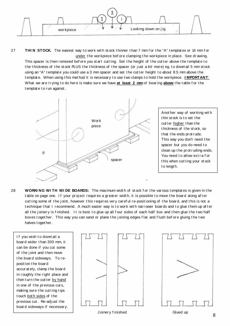
27 THIN STOCK. The easiest way to work with stock thinner than 7 mm for the “A” templates or 14 mm for under the workpiece before clamping the workpiece in place. See drawing.
This spacer is then removed before you start cutting. Set the height of the cutter above the template to the thickness of the stock PLUS the thickness of the spacer (or just a bit more) eg. to dovetail 5 mm stock using an “A” template you could use a 3 mm spacer and set the cutter height to about 8.5 mm above the template. When using this method it is necessary to use two clamps to hold the workpiece. IMPORTANT: What we are trying to do here is make sure we have at least 2 mm of bearing above the table for the template to run against.
28 WORKING WITH WIDE BOARDS: The maximum width of stock for the various templates is given in the table on page one. If your project requires a greater width, it is possible to move the board along after cutting some of the joint, however this requires very careful re-positioning of the board, and this is not a technique that I recommend. A much easier way is to work with narrower boards and to glue them up after all the joinery is finished. It is best to glue up all four sides of each half box and then glue the two half boxes together. This way you can sand or plane the joining edges flat and flush before gluing the two halves together.
workpiece Looking down on jig
Joinery finished Glued up 8
Work piece
spacer
Another way of working with thin stock is to set the cutter higher than the thickness of the stock, so that the ends protrude. This way you don’t need the spacer but you do need to clean up the protruding ends. You need to allow extra for this when cutting your stock to length.
If you wish to dovetail a board wider than 300 mm, it can be done if you cut some of the joint and then move the board sideways. To re-position the board accurately, clamp the board in roughly the right place and then turn the cutter by hand in one of the previous cuts, making sure the cutting tips touch both sides of the previous cut. Re-adjust the board sideways if necessary.

29 SPLIT BOX: If dovetailing a box and then splitting the box in half to form the lid, it is possible to increase the width of one of the pins (or the width of the space between the pins) to allow for the width of the saw cut. To do this you need a spacer the same width as the saw kerf, which is placed between the workpiece and the stop for cutting some of the joint only. It is best to mark a line on all pieces where the finished box is going to be split. Start by positioning the workpiece as usual to get the joint layout required, but put the spacer between the work and the stop when locking the stop in place. Working from the STOP side of the workpiece, cut the joint as far as the line and then remove the spacer before finishing the cut. This same procedure is used for both halves of each joint. It is worth practicing this method before starting a project, so you fully understand how it works:
spacer stop
Cut these with spacer in
stop
Cut these with spacer out
9
For more details on the split box idea, see note 31 on page 10 and also pages 23 & 24

30 Symmetrical layout (as in note 17) works best when the width of the stock is a whole multiple of the pin spacing, or a few mm more. Multiples of the pin spacing for the different templates are:
These widths do not have to be exact. If the joint has a half pin top and bottom, make the width a few mm more than given above. If it is any less the half pins would be too narrow. If the joint has full pins only, the width can be a bit more or a bit less than given above.
31 Variable Spacing Upgrade (VSU). Contrary to popular belief, it is possible to cut variable spaced dovetails using a fixed space template. This technique is an adaptation of the Split box idea (Note 29 above) and was suggested by David Charlsworth (Devon, England). With this method, you can adjust the template to fit the wood – rather than the other way around! It also gives a joint that looks more like a hand cut dovetail. Consider the situation: We wish to dovetail a box with 90 mm sides (with a half pin top and bottom) using the A10 template. From Note 30 we see that 82 mm works well with this template. If we increase the width of the centre pin by 8 mm, then the 90 mm stock would work well on the A10 template. To do this we use an 8 mm spacer when cutting some of the joint, in exactly the same way as described in Note 29. (The spacer could be a few mm LESS than 8 mm, but should not be any more or the half pins would be too narrow). The finished joint would look like this:
This technique is so useful that I will describe the process in full detail for the situation above (90 mm stock and an 8 mm spacer on the A10 template). The situation I am describing assumes that all 4 pieces of stock are the same width, so that we can turn the stock end for end without moving the stop. Stand the stock on the jig above the tapered fingers and locate sideways so that the stock is symmetrical across the fingers:
H10 H20 A10 A20 B10 B20
18 26 21 28 38 48
36 52 41 56 76 96
54 78 62 84 114 144
72 104 82 112 152 192
90 etc.
130 103 140 190 240
Half pin top & bottom Full pins only
Same overhang either side
Centre pin 8 mm wider than regular pins
10
It is very important that you mark a line on the outside face of all 4 sides to show where you are going to add the extra width.
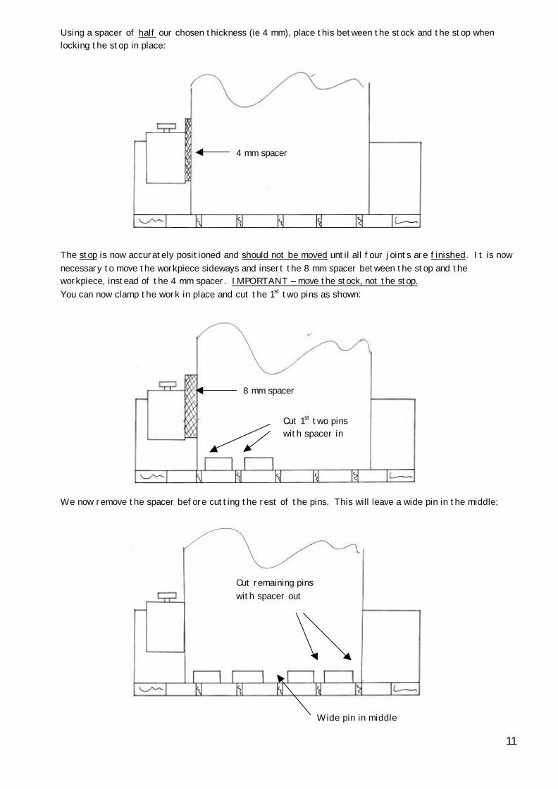
Using a spacer of half our chosen thickness (ie 4 mm), place this between the stock and the stop when locking the stop in place:
The stop is now accurately positioned and should not be moved until all four joints are finished. It is now necessary to move the workpiece sideways and insert the 8 mm spacer between the stop and the workpiece, instead of the 4 mm spacer. IMPORTANT – move the stock, not the stop. You can now clamp the work in place and cut the 1st two pins as shown:
We now remove the spacer before cutting the rest of the pins. This will leave a wide pin in the middle;
Wide pin in middle
Cut remaining pins with spacer out
8 mm spacer
Cut 1st two pins with spacer in
4 mm spacer
11

We now change cutters and work on the other side of the jig to cut the dovetail slots. Once again, put the 8 mm spacer in to cut the slots from the stop to the middle of the board. Remove the spacer to cut the remaining slots. In this case, we will make the centre dovetail slot wider to accommodate the wide pin. This means that you have to machine the centre slot twice, once with the spacer in and once with the spacer out. All the boards can now be turned end for end to repeat these cutting operations for the remaining joints, following exactly the same procedure.
In the above example there were 5 pins, so we could make the centre pin wider and still have a symmetrical joint. If you have an even number of pins, you can make the space between the middle two pins wider to achieve a symmetrical joint:
The procedure is the same, although this time we machine all the dovetail slots once and we machine the space between the centre two pins twice. Practice on some offcuts first so you fully understand this technique before starting your project.
32 Re-adjusting Shims. If changing from a very hard wood to a very soft wood or vice versa, it is worth cutting a trial joint to check the shim adjustment. Very hard woods may require 1 or 2 more shims than soft woods to give the fit that you want. If you find that this is the case, make a note of the shims required & the timber species for next time.
ANGLED DOVETAILS It is possible to cut angled dovetails so that all the sides of the box slope in or out by up to about 15° (see note below). To do this, prepare the stock with the ends cut at the appropriate angle. It is necessary to make an angled block to go between the stop and the workpiece, as shown below:
To cut the dovetails, stand the workpiece on the jig with it’s end flush against the template (This means the workpiece will be sloping rather than standing vertically). Locate sideways to get the required layout of the joint, remembering that the cuts are at an angle to the long edges of the boards and so will need to be positioned carefully:
Extra space between centre pins
Sizes only aprox.
12
Angle of sides
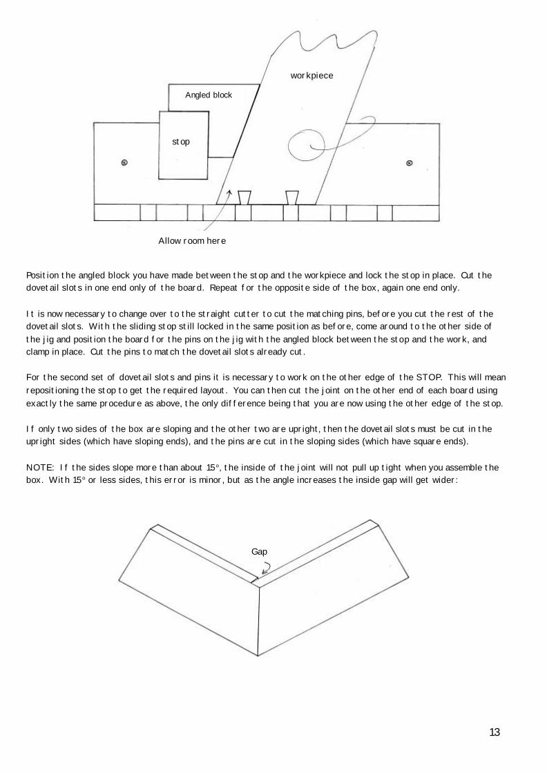
Position the angled block you have made between the stop and the workpiece and lock the stop in place. Cut the dovetail slots in one end only of the board. Repeat for the opposite side of the box, again one end only. It is now necessary to change over to the straight cutter to cut the matching pins, before you cut the rest of the dovetail slots. With the sliding stop still locked in the same position as before, come around to the other side of the jig and position the board for the pins on the jig with the angled block between the stop and the work, and clamp in place. Cut the pins to match the dovetail slots already cut. For the second set of dovetail slots and pins it is necessary to work on the other edge of the STOP. This will mean repositioning the stop to get the required layout. You can then cut the joint on the other end of each board using exactly the same procedure as above, the only difference being that you are now using the other edge of the stop. If only two sides of the box are sloping and the other two are upright, then the dovetail slots must be cut in the upright sides (which have sloping ends), and the pins are cut in the sloping sides (which have square ends). NOTE: If the sides slope more than about 15°, the inside of the joint will not pull up tight when you assemble the box. With 15° or less sides, this error is minor, but as the angle increases the inside gap will get wider:
Gap
Allow room here
workpiece
Angled block
stop
13
CUTTING FOUR JOINTS FOR A BOX OR DRAWER There are two common situations:
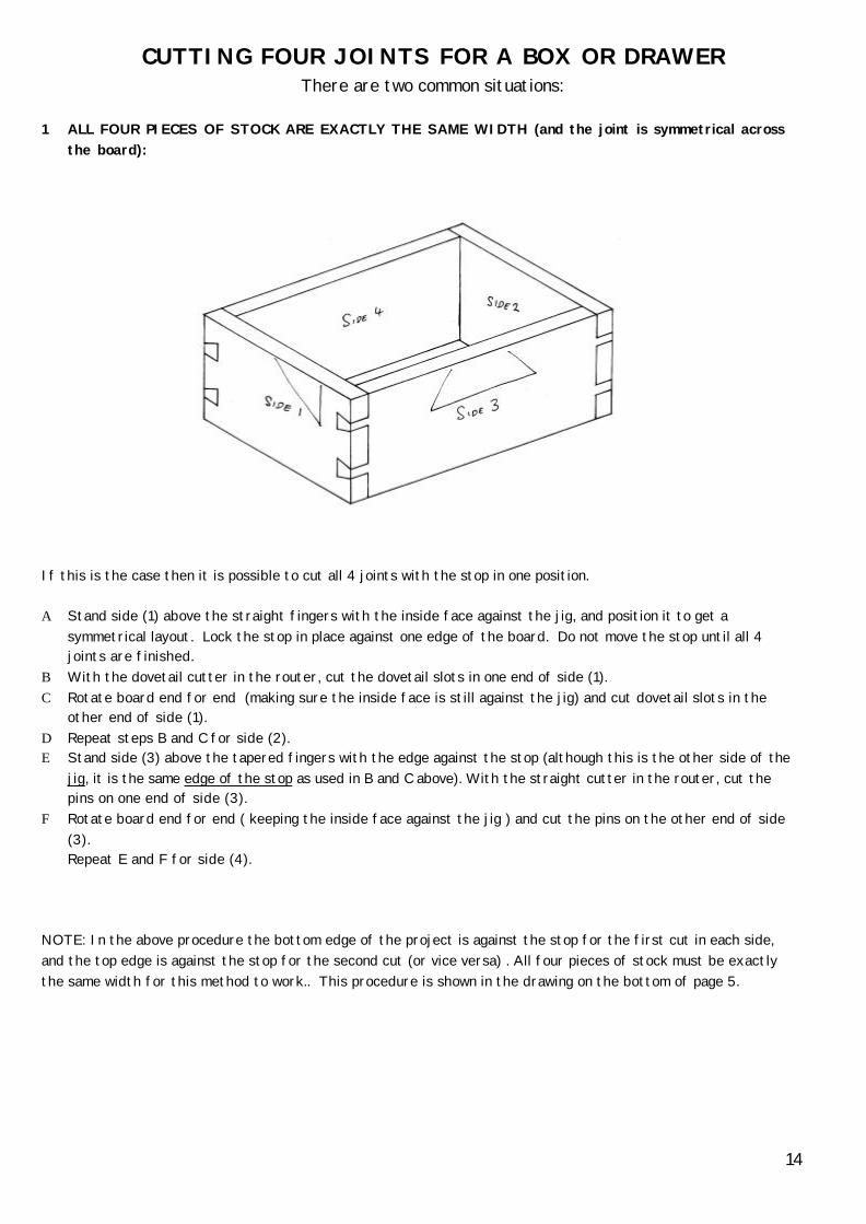
1 ALL FOUR PIECES OF STOCK ARE EXACTLY THE SAME WIDTH (and the joint is symmetrical across
the board): If this is the case then it is possible to cut all 4 joints with the stop in one position. Α Stand side (1) above the straight fingers with the inside face against the jig, and position it to get a
symmetrical layout. Lock the stop in place against one edge of the board. Do not move the stop until all 4 joints are finished.
B With the dovetail cutter in the router, cut the dovetail slots in one end of side (1). C Rotate board end for end (making sure the inside face is still against the jig) and cut dovetail slots in the
other end of side (1). D Repeat steps B and C for side (2). E Stand side (3) above the tapered fingers with the edge against the stop (although this is the other side of the
jig, it is the same edge of the stop as used in B and C above). With the straight cutter in the router, cut the pins on one end of side (3).
F Rotate board end for end ( keeping the inside face against the jig ) and cut the pins on the other end of side (3). Repeat E and F for side (4).
NOTE: In the above procedure the bottom edge of the project is against the stop for the first cut in each side, and the top edge is against the stop for the second cut (or vice versa) . All four pieces of stock must be exactly the same width for this method to work.. This procedure is shown in the drawing on the bottom of page 5.
14
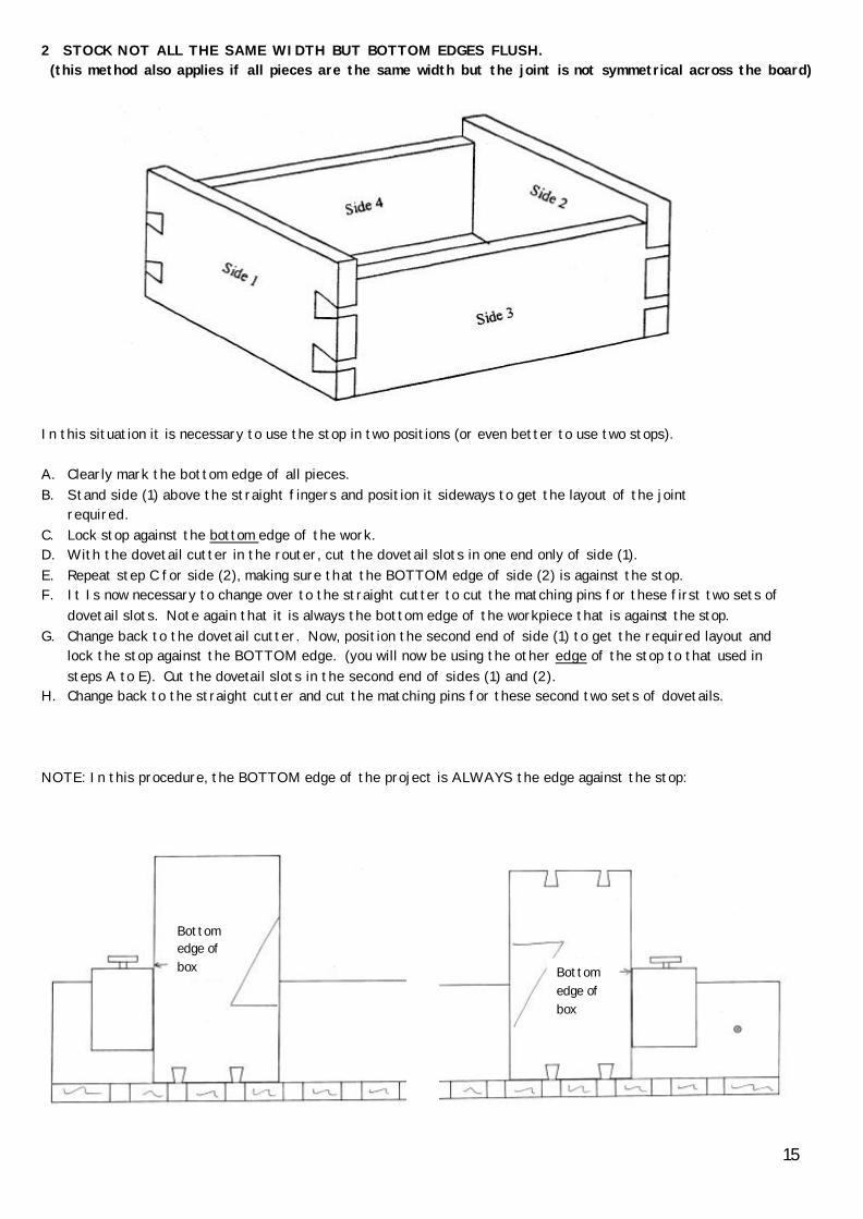
2 STOCK NOT ALL THE SAME WIDTH BUT BOTTOM EDGES FLUSH. (this method also applies if all pieces are the same width but the joint is not symmetrical across the board)
In this situation it is necessary to use the stop in two positions (or even better to use two stops). A. Clearly mark the bottom edge of all pieces. B. Stand side (1) above the straight fingers and position it sideways to get the layout of the joint
required. C. Lock stop against the bottom edge of the work. D. With the dovetail cutter in the router, cut the dovetail slots in one end only of side (1). E. Repeat step C for side (2), making sure that the BOTTOM edge of side (2) is against the stop. F. It Is now necessary to change over to the straight cutter to cut the matching pins for these first two sets of
dovetail slots. Note again that it is always the bottom edge of the workpiece that is against the stop. G. Change back to the dovetail cutter. Now, position the second end of side (1) to get the required layout and
lock the stop against the BOTTOM edge. (you will now be using the other edge of the stop to that used in steps A to E). Cut the dovetail slots in the second end of sides (1) and (2).
H. Change back to the straight cutter and cut the matching pins for these second two sets of dovetails. NOTE: In this procedure, the BOTTOM edge of the project is ALWAYS the edge against the stop:
Bottom edge of box Bottom
edge of box
15

GIFKINS ROUTER TABLE
This design will only work for routers that have a base plate held on with 3 or 4 screws. Router tables need to be rigid, flat and to offer support for the workpiece right up to the cutter. It is quick and inexpensive to make your own table that meets all these requirements. The following design can held in a vice, it can have a small stand for use on a bench top, or it can be floor mounted. This design has a single piece top rather than using a inset table to mount the router on, as is usually the case. This has two advantages: 1. The table top is perfectly flat right up to the cutter, with no problems of aligning a inset table level with the
rest of the table. 2. With an inset table, unless it is rigidly locked in place to the outer table, there is a chance of movement of the
inset/router assembly relative to the rest of the table. This can be a problem if your fence is clamped to the outer table.
TOP (SHEET A) Two sheets of Lamipanel glued together with contact cement. Use the base from your router to lay out the mounting holes in the center of the sheet. The central hole should be larger than the template follower that your router takes (see note below). This way you can fit the template follower without having to remove the router from the table and also you can use the template follower mounting holes to secure table inserts in place. SUPPORT (SHEET B) 16mm or 18mm craftwood or plywood as support for the top. The top should be glued to this with contact cement. The hole in the middle should be 10mm or15mm larger than the base of your router so that your router sits up through this support. BASE (SHEET C) An extra sheet of Lamipanel glued under the craftwood makes the table much more rigid and stops the table from sagging over time. It also stops uneven absorption of moisture into the craftwood. This extra sheet is important for a good table.
Top (sheet A)
Support (sheet B)
Base (sheet C) 16

For vice or bench top use the table could be as small as 300mm x 500mm although larger (say 400mm x 600mm) is more useful. For a floor standing model a minimum size for stability is about 500mm x 700mm. Material for the table surface needs to be 4mm to 6mm thick, reasonable hard and not brittle. I have used two sheets of 3mm Lamipanel (made by Laminex Industries) glued together with contact cement for my tables and this works well. NOTE: Lamipanel is a sheet material (laminated phenolic resin) made for wet area wall paneling such as shower recesses. Similar products should be available in most countries. A single sheet of 3mm Lamipanel does not offer enough support for the router once screws have been countersunk into it. Other materials that would be suitable are Polycarbonate, Phenolic Resin, Aluminium and no doubt many other materials. Please let me know if you find a readily available material that works well so that I can update these instructions. Whatever the material is its thickness should be in the 4mm to 6mm range. The following plan assumes you are using Lamipanel. Cut all the holes in the three sheets before gluing up. These holes do not need to be perfectly round or smooth, as long as the holes in sheets B and C are bigger than the router base and the hole in sheet A is larger than the mounting holes for the template follower (see later).
You can use this same method to cut the smaller hole in sheet A. For this you would need to cut a new sheet of ply, with a hole in the center such that; Dia. of hole in ply = Dia. of router base + Dia. of finished hole in Top sheet – dia. of bit HINT: If you cut hole A first, then you can re-cut the same sheet of ply to use for the two larger holes in sheets B and C.
HOLES IN SHEETS A neat way of cutting the holes in sheet B and sheet C is to start with a sheet of 3mm ply or craftwood the same size as your table. Measure the diameter of your router base and double this figure (this idea only works if your router has a round base!). Draw a circle this size in the CENTER of the 3mm ply and use a bandsaw or scroll saw to cut this circle out. It is OK to cut in from the edge of the sheet with the bandsaw to cut this circle out. Don’t fuss too much to get this hole neat, a couple of mm either side of the line is OK. Now, clamp this 3mm ply to sheet B and use a ½” straight (plunge) bit to plunge through sheet B. Warning: Use a waste sheet under sheet B so you do not damage your work bench! With the base of the router running against the inside of the hole we have cut in the 3mm ply, cut the hole in sheet B, cutting in a clockwise direction. It is best to do this in two passes, only going half-way through the first time. This hole should end up the diameter of the router base PLUS the diameter of the plunge bit you are using. Repeat this process for sheet C.
Cut holes in sheet A this size
Mounting holes for template follower
17

SCREW HOLES Once cut, use the base plate from the router to accurately lay out the screw holes. Locate the base plate concentrically with the hole you have just cut in sheet A and carefully mark the position of the screw holes. Remember to position these holes so that the router’s position in the table will make it easy to change bits. These mounting holes need to be as accurate as possible. To mount the router in the finished table, remove the base plate and use the same screws to secure the router to the table. You may need to use longer screws if your table top is thick. I have used Makita and Ryobi routers in this table design, using the four M4 (ie 4mm dia) screws that came with the router, and this is perfectly adequate to hold the router securely. VICE MOUNT To hold the table top in a vice, screw a block of wood (about 50mm x 50mm) underneath the back edge of the table. Make sure this block is clear of the router so that it can be clamped in the vice to support the table. STAND A stand for the table can be made out of 12mm craftwood or plywood, and it can be attached to the table by screwing two cleats to the underside of the table top. It is best if these legs and cleats are narrower than the table so there is space to clamp a fence in any position on the table top without the legs fouling the clamp. BENCH TOP FLOOR MOUNTED
Do not enclose the router under the table as the router will overheat without a free flow of air.
router
300
250
850
500
800
600
400
500
Table
18
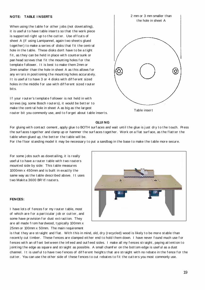
NOTE: TABLE INSERTS When using the table for other jobs (not dovetailing), it is useful to have table inserts so that the work piece is supported right up to the cutter. Use offcuts of sheet A (if using Lamipannel, again two sheets glued together) to make a series of disks that fit the central hole in the table. These disks don’t have to be a tight fit, as they can be held in place with countersunk or pan head screws that fit the mounting holes for the template follower. It is best to make them 2mm or 3mm smaller than the hole in sheet A as this allows for any errors in positioning the mounting holes accurately. It is useful to have 3 or 4 disks with different sized holes in the middle for use with different sized router bits. If your router’s template follower is not held in with screws (eg. some Bosch routers), it would be better to make the central hole in sheet A as big as the largest router bit you commonly use, and to forget about table inserts.
GLUING For gluing with contact cement, apply glue to BOTH surfaces and wait until the glue is just dry to the touch. Press the surfaces together and clamp up or hammer the surfaces together. Work on a flat surface, as the flatter the table when glued up, the better the table will be. For the floor standing model it may be necessary to put a sandbag in the base to make the table more secure. For some jobs such as dovetailing, it is really useful to have a router table with two routers mounted side by side: This table measures 1000mm x 450mm and is built in exactly the same way as the table described above. It uses two Makita 3600 BR ½” routers. FENCES: I have lots of fences for my router table, most of which are for a particular job or cutter, and some have provision for dust extraction. They are all made from hardwood, typically 100mm x 25mm or 100mm x 50mm. The main requirement is that they are straight and flat. With this in mind, old, dry (recycled) wood is likely to be more stable than recently cut timber. These fences are clamped either end to hold them down. I have never found much use for fences with an offset between the infeed and outfeed sides. I make all my fences straight, paying attention to jointing the edge as square and straight as possible. A small chamfer on the bottom edge is useful as a dust channel. It is useful to have two fences of different heights that are straight with no rebate in the fence for the cutter. You can use the other side of these fences to cut rebates to fit the cutters you most commonly use.
Table insert
2 mm or 3 mm smaller than the hole in sheet A
19
EXTRA NOTES:
• The method described in 31 above was used to make the pins (or the gap between the pins) WIDER. It can also be used to make the gap between the pins NARROWER on some templates (this will not work on the H10 or A10 templates). To do this you would ADD spacers as you work away from the stop. It is not possible to make the pins narrower (as their size is determined by the size of the dovetail cutter). Also, it is not possible to make the pins closer together than the diameter of the straight cutter. Much more care is needed if you are making pins closer together, as it would be easy to machine away too much wood when cutting the pins. Try this technique out on offcuts to see how it works.
• If using method 31, you should be aware that each time you unclamp and clamp the work in place you introduce small errors in positioning. If you were to vary every spacing across the joint there may be problems with the fit of the joint, as it would be difficult to reposition both halves of the joint in exactly the same way. These methods are best used to vary only one pin or only one space between the pins.
• It is worth recording the number of shims needed for each template to give a good fitting joint. This way, you can set the shims exactly when changing templates back and forth, without the need for further trial joints:
A10 Shims …………..
A20 Shims …………..
B10 Shims …………..
B20 Shims …………..
H10 Shims …………..
H20 Shims …………..
• It is possible to leave pins out to vary the spacing of the joint, but this requires an extra step or two. When cutting the dovetails, simply leave out any dovetail slots that you wish. With the pins, it is necessary to cut ALL the pins in the normal manner, and then machine away any pins that you don’t want. This is best done half a pin at a time. After cutting all the pins, move the work sideways by about half the width of a pin. Clamp in place and machine away one side of any pins you don’t want. Then move the work to the other side of the original position by about half a pin; clamp in place and machine away the remaining part of the pins. This method ensures that some of the remaining pins are always standing on the template fingers.
• It is useful to thickness a piece of material to the same thickness as the template, to use when setting the cutter height. You need a thicker piece for the “B” templates than for the “A” or “H” templates.
• If you send your cutters out to get them resharpened, always check that the grub screws are tight and that the bearings run free before using the sharpened cutters. Some sharpening shops are very careless about re-assembling cutters.
• Get in the habit of spinning the bearings by hand now and then to make sure they run free. Apply oil regularly.
• I use quick action clamps to hold the work to the jig, and I have glued a piece of leather to the jaw of the clamp so that the clamp doesn’t mark the work. This leather also has a bit of give, which helps to hold the work more securely.
• If you don’t have an accurate saw bench for preparing your stock, a shooting board (using a hand plane) can produce very accurate results with very little effort.
• If you are allowing ½ mm overhang each end when setting the cutter height, don’t forget to allow for this when cutting your stock to length.
20

Edge Misalignment There are a number of factors that impact on the edge alignment of the joints, and it can be quite difficult to determine which one is causing problems.
1. Timber not square 2. Stop not square 3. Not clamping wood vertically on jig 4. Turning wood inside out to cut the second end 5. Turning end for end (with stop in the same position) with unequal width timber 6. Not clamping wood tight against stop
It is more than likely that errors are a combination of the points above, with small errors adding together to create the problem. # 1 See instructions, note 23 on page 6. If you have difficulty preparing stock square, it can be achieved quickly and easily using a shooting board and a hand plane. #2 Jigs sold after March 2003 should give perfect alignment. There were a few of the blue aluminium stops made before this that we subsequently found were inaccurately machined, and also the earlier timber stops could occasionally loose their accuracy if the timber moved. To check that the stop is square, use a square from either side of the jig and measure any gaps between the square and the stop with feeler gauges. Compare the results with CASES 1, 2 and 3 on page 22. This method is only approximate, as there is sometimes a slight curvature in the backing boards. This curvature does not have any effect on the function of the jig, but can make it very difficult to check the accuracy of the stop. If the stop is square, then it must be the timber preparation and /or the procedure that is causing the problem. #3 Once you have clamped the timber to the jig, have a close look to make sure the timber is sitting flat against the template. See instructions, note 22 page 6. #4 The OUTSIDE of the box or drawer must always be facing out from the jig. It is vital to keep this in mind when turning the board end for end. See instructions, note 18 page 5. #5 You can only turn end for end (with the stop in the one position) if all the boards are exactly the same width AND the joint is roughly symmetrical across the board. See pages 14 and 15 in the instructions. #6 As for #3 above, check that the workpiece is hard up against the stop after clamping it in place. Until you get in the habit of using the clamp with one hand, it can be difficult to hold the workpiece against the jig AND against the stop whilst clamping in place. This is probably the most common reason for misaligned joints. A careful visual inspection after clamping will eliminate most problems.
21

CASE 1 Square accurate, stop not accurate: Gaps are equal CASE 2 Stop accurate, square not accurate: Equal gaps On opposite sides CASE 3 Stop not accurate, square not accurate:
Gaps are unequal
22
Cut rest of joint with spacer out
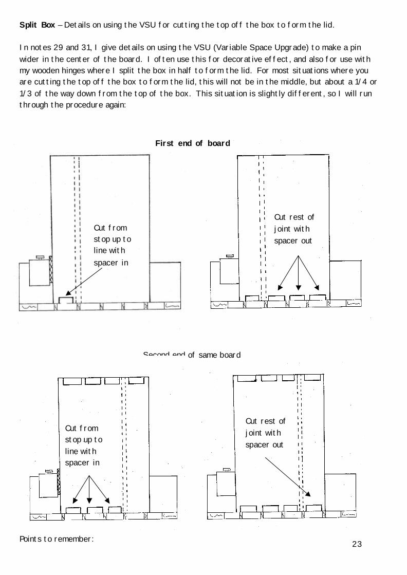
Split Box – Details on using the VSU for cutting the top off the box to form the lid. In notes 29 and 31, I give details on using the VSU (Variable Space Upgrade) to make a pin wider in the center of the board. I often use this for decorative effect, and also for use with my wooden hinges where I split the box in half to form the lid. For most situations where you are cutting the top off the box to form the lid, this will not be in the middle, but about a 1/4 or 1/3 of the way down from the top of the box. This situation is slightly different, so I will run through the procedure again: Points to remember:
Cut from stop up to line with spacer in
First end of board
Second end of same board
Cut from stop up to line with spacer in
Cut rest of joint with spacer out
23

1. For this to work, you must start by positioning the board symmetrically across the
fingers. 2. As described in note 31 (page 10), to position the stop you use a spacer only ½ as thick as
your saw kerf. You then use a spacer the same thickness as your saw kerf for all the dovetailing.
3. It is vital that you mark a line on all the boards where you are going to add the extra width to allow for the saw kerf.
4. In all situations you cut from the stop up to the line with the spacer in. 5. In all situations you cut the rest of the joint with the spacer out (ie. from the line up to
the edge away from the stop) 6. If you are making the pin wider (as above), then you cut the dovetail slot where the line
is TWICE, once with the spacer in and once with the spacer out (this is when using the dovetail cutter).
7. If you are making the gap between the pins wider, then you cut the gap between the pins twice, once with the spacer in and once with the spacer out (this is when using the straight cutter).
There are lots of different situations depending on the size of the project, the template you are using and how far down you want to cut the lid off, so it is important to practice on offcuts to see how your particular situation will work.
24


![No measuring! No fiddling! No fuss! - Gifkins Dovetail · STANDARD DELUXE PACKAGE $515 [Save $35] A jig with two templates with cutters. The popular choice is the A10 ... 03—TGTC](https://static.fdocuments.in/doc/165x107/5afcf0d37f8b9a994d8cca03/no-measuring-no-fiddling-no-fuss-gifkins-dovetail-deluxe-package-515-save.jpg)