Gibraltar Harbour Site Survey and Installation Of a Radar ... Proudman Oceanographic Laboratory...
26
No. 179 Gibraltar Harbour Site Survey and Installation Of a Radar Tide Gauge D. E. Smith, L. J. Bradley & S. Holgate July 2006
Transcript of Gibraltar Harbour Site Survey and Installation Of a Radar ... Proudman Oceanographic Laboratory...

No. 179
Gibraltar Harbour
Site Survey and Installation Of a Radar Tide Gauge
D. E. Smith, L. J. Bradley & S. Holgate
July 2006

1
Proudman Oceanographic Laboratory
Internal Document No. 179
GIBRALTAR HARBOUR
SITE SURVEY AND INSTALLATION OF A
RADAR TIDE GAUGE
D. E. Smith, L. J. Bradley & S. Holgate
Proudman Oceanographic Laboratory Joseph Proudman Building
6 Brownlow Street Liverpool
July 2006
2
1 Introduction This report contains details of a survey and installation of a tide gauge system at the Port of Gibraltar. The Royal Navy has operated a tide gauge from 1961 however the system is obsolete and requires replacement. The Permanent Service for Mean Sea Level, PSMSL has been concerned with the reliability of the gauge and the quality of the data over recent years. The Director of the PSMSL wrote in July 2002 to the Captain of the Port, Gibraltar Port Authority proposing the installation of a new tide gauge system. The port accepted the proposal in principle and funding was provided by the Port Authority in March 2003.
2 Survey
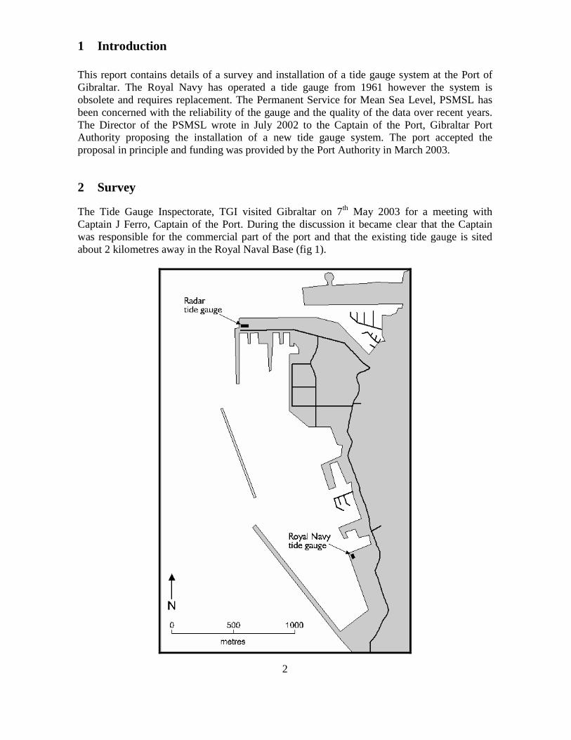
The Tide Gauge Inspectorate, TGI visited Gibraltar on 7th May 2003 for a meeting with Captain J Ferro, Captain of the Port. During the discussion it became clear that the Captain was responsible for the commercial part of the port and that the existing tide gauge is sited about 2 kilometres away in the Royal Naval Base (fig 1).
3
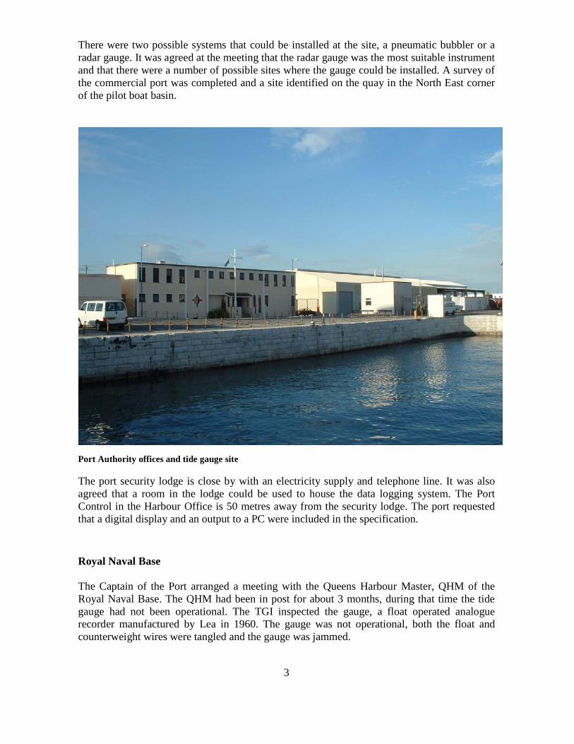
There were two possible systems that could be installed at the site, a pneumatic bubbler or a radar gauge. It was agreed at the meeting that the radar gauge was the most suitable instrument and that there were a number of possible sites where the gauge could be installed. A survey of the commercial port was completed and a site identified on the quay in the North East corner of the pilot boat basin.
Port Authority offices and tide gauge site The port security lodge is close by with an electricity supply and telephone line. It was also agreed that a room in the lodge could be used to house the data logging system. The Port Control in the Harbour Office is 50 metres away from the security lodge. The port requested that a digital display and an output to a PC were included in the specification. Royal Naval Base The Captain of the Port arranged a meeting with the Queens Harbour Master, QHM of the Royal Naval Base. The QHM had been in post for about 3 months, during that time the tide gauge had not been operational. The TGI inspected the gauge, a float operated analogue recorder manufactured by Lea in 1960. The gauge was not operational, both the float and counterweight wires were tangled and the gauge was jammed.

4
Royal Naval base Lea Gauge With the help of the QHM the wires were removed and refitted. The person responsible for the tide gauge was away on leave and equipment wasn’t available to accurately set the gauge on datum. The visual tide staff was also missing, so the QHM estimated the sea level and the gauge was set to that height. The TGI gave the QHM instructions on how to set the gauge on datum. Bench Marks A survey of bench marks in the Royal Naval base and on town walls was carried out. A full description of the marks is given in Appendix A
5
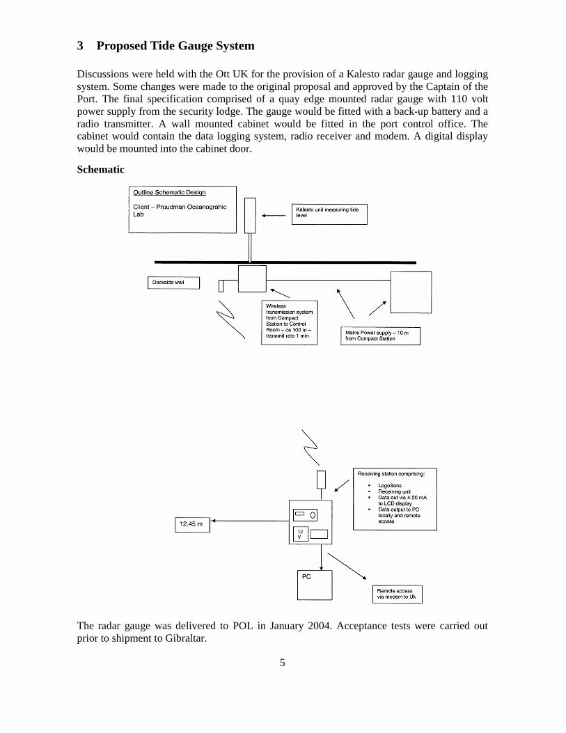
3 Proposed Tide Gauge System Discussions were held with the Ott UK for the provision of a Kalesto radar gauge and logging system. Some changes were made to the original proposal and approved by the Captain of the Port. The final specification comprised of a quay edge mounted radar gauge with 110 volt power supply from the security lodge. The gauge would be fitted with a back-up battery and a radio transmitter. A wall mounted cabinet would be fitted in the port control office. The cabinet would contain the data logging system, radio receiver and modem. A digital display would be mounted into the cabinet door.
Schematic
The radar gauge was delivered to POL in January 2004. Acceptance tests were carried out prior to shipment to Gibraltar.

6
4 Installation Dave Smith and Les Bradley from the TGI together with Simon Holgate PSMSL visited Gibraltar in April 2004 to install the tide gauge system. An electrical contractor had cut a trench between the security lodge and the tide gauge. A duct and cable were laid providing a 110 volt supply. The radar gauge stanchion was bolted to the quay and adjusted so that the stanchion was vertical. The Kalesto radar head was mounted horizontally protected by a stainless steel cover with a 45˚ end plate to deflect the radar beam down to the sea surface. A weather proof housing was attached to the radar gauge stanchion. The housing contains a power control unit, signal converter, back-up battery and RS232 radio transmitter. The data is transmitted to the Port office some 50 metres from the gauge
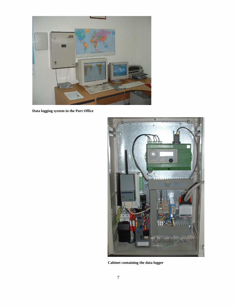
Radar gauge and housing layout A cabinet containing the data logger, power control unit, back-up battery, radio receiver and modem was mounted in the port control. The data can be accessed locally on an office PC and via the modem. The data is collected weekly by the British Oceanographic Data Centre, BODC at POL were it is quality checked and data banked. A second POL system collects data every hour and displays it on the POL web site. Circuit diagrams of the transmitter and receiver are shown in Annex B.
7
Data logging system in the Port Office
Cabinet containing the data logger
8
5 Levelling
A domed brass bolt the Tide Gauge Bench Mark TGBM (CP) was installed close to the base of the radar gauge stanchion. Levelling was carried out between the TGBM (RN), Royal Naval Base and the TGBM (CP), Commercial Port using a Zeiss Dini 10 level and Zeiss telescopic staff. Unfortunately it rained heavily for 2 days and the levelling could not be completed. The datum of the radar system was derived from reading taken from the tide gauge in the Royal Naval Base
A second visit was made in September 2004 to complete the levelling. The first levelling was carried out from The TGBM (RN) base to the entrance. After completing the first leg of the levelling it was noted that there was a closing error. The levelling was repeated and there was still an error but different from the first. The level was inspected and in was found that it had been damaged in transit. The TGI had brought equipment to accurately set the datum of the Lea gauge in the Royal Naval base. The Lea gauge was maintained with a new pen arm and pen being fitted. The gauge was then set on datum. It was noted that the chart drum was not rotating. The power supply to the electric motor had failed, the Assistant Queens Harbour Master was informed of the fault, but a repair could not be carried out during our visit. Again readings from the Royal Naval Base gauge were telephoned to the commercial port. It was found that there new radar gauge had a 4 cm datum error, this error was corrected
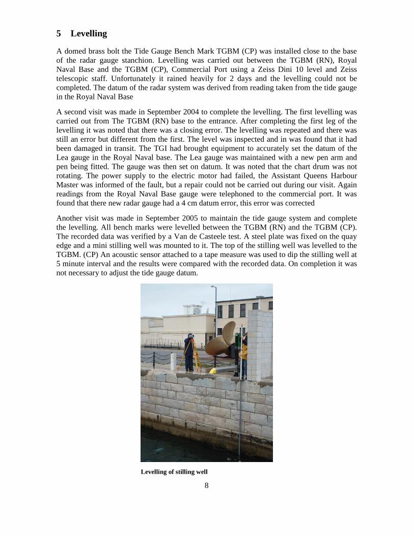
Another visit was made in September 2005 to maintain the tide gauge system and complete the levelling. All bench marks were levelled between the TGBM (RN) and the TGBM (CP). The recorded data was verified by a Van de Casteele test. A steel plate was fixed on the quay edge and a mini stilling well was mounted to it. The top of the stilling well was levelled to the TGBM. (CP) An acoustic sensor attached to a tape measure was used to dip the stilling well at 5 minute interval and the results were compared with the recorded data. On completion it was not necessary to adjust the tide gauge datum.
Levelling of stilling well
9
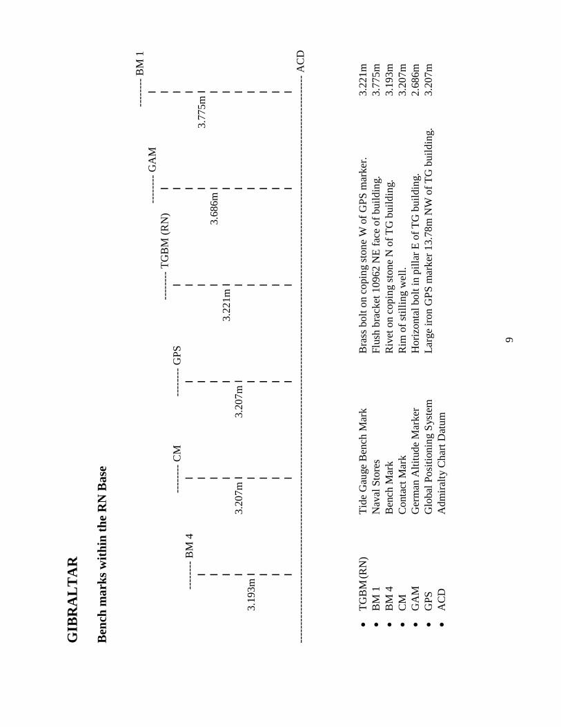
GIB
RA
LT
AR
B
ench
mar
ks w
ithi
n th
e R
N B
ase
---
----
- B
M 1
---
----
- G
AM
I
-
----
---
TG
BM
(R
N)
I
I
---
----
- C
M
---
----
- G
PS
I
I
I
---
----
- B
M 4
I
I
I
I
I
I
I
I
I
I
3.
775m
I
I
I
I
I
3.68
6m I
I
I
I
I
3.
221m
I
I
I
I
3.
207m
I
3.20
7m I
I
I
I 3.
193m
I
I
I
I
I
I
I
I
I
I
I
I
I
I
I
I
I
I
I
I
I
I
I
I
----
----
----
----
----
----
----
----
----
----
----
----
----
----
----
----
----
----
----
----
----
----
----
----
----
----
----
----
----
----
----
----
----
----
----
----
----
----
----
---
AC
D
•
TG
BM
(RN
)
Tid
e G
auge
Ben
ch M
ark
B
rass
bol
t on
copi
ng s
tone
W o
f G
PS
mar
ker.
3.22
1m
• B
M 1
N
aval
Sto
res
Fl
ush
brac
ket 1
0962
NE
fac
e of
bui
ldin
g.
3.77
5m
• B
M 4
B
ench
Mar
k
Riv
et o
n co
ping
sto
ne N
of
TG
bui
ldin
g.
3.19
3m
• C
M
Con
tact
Mar
k
Rim
of
still
ing
wel
l.
3.20
7m
• G
AM
G
erm
an A
ltitu
de M
arke
r
Hor
izon
tal b
olt i
n pi
llar
E o
f T
G b
uild
ing.
2.
686m
•
GPS
G
loba
l Pos
itio
ning
Sys
tem
Lar
ge ir
on G
PS
mar
ker
13.7
8m N
W o
f T
G b
uild
ing.
3.
207m
•
AC
D
Adm
iral
ty C
hart
Dat
um
10
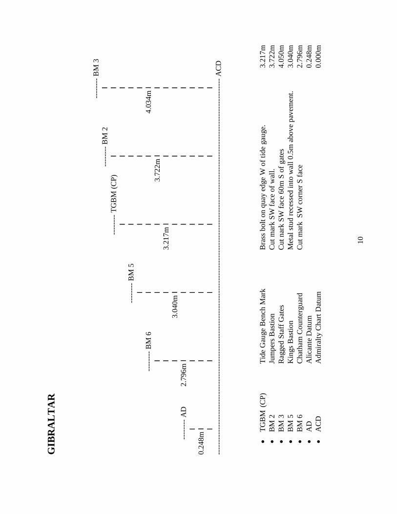
GIB
RA
LT
AR
---
----
- B
M 3
-
----
---
BM
2
I
-
----
---
TG
BM
(C
P)
I
I
I
I
I
-
----
---
BM
5
I
I
I
I
I
I
I
---
----
- B
M 6
I
I
I
4.03
4m I
I
I
I
3.72
2m I
I
I
I
3.21
7m I
I
I
I
3.04
0m I
I
I
I
-
----
---
AD
2.
796m
I
I
I
I
I
I
I
I
I
I
I
0.24
8m I
I
I
I
I
I
I
I
I
I
I
I
----
----
----
----
----
----
----
----
----
----
----
----
----
----
----
----
----
----
----
----
----
----
----
----
----
----
----
----
----
----
----
----
----
----
----
----
----
- A
CD
• T
GB
M (
CP
)
Tid
e G
auge
Ben
ch M
ark
B
rass
bol
t on
quay
edg
e W
of
tide
gau
ge.
3.21
7m
• B
M 2
Ju
mpe
rs B
asti
on
Cut
mar
k S
W f
ace
of w
all.
3.72
2m
• B
M 3
R
agge
d St
aff
Gat
es
Cut
nar
k S
W f
ace
60m
S o
f ga
tes
4.
050m
•
BM
5
Kin
gs B
asti
on
Met
al s
tud
rece
ssed
into
wal
l 0.5
m a
bove
pav
emen
t.
3.04
0m
• B
M 6
C
hath
am C
ount
ergu
ard
C
ut m
ark
SW
cor
ner
S fa
ce
2.79
6m
• A
D
Alic
ante
Dat
um
0.24
8m
• A
CD
A
dmir
alty
Cha
rt D
atum
0.00
0m

11
Ben
ch M
ark
Loc
atio
n an
d D
escr
ipti
on
Mar
k G
PS
Loc
atio
n (
WG
S84)
D
escr
ipti
on
Hei
ght
(m)
TG
BM
(R
N)
36˚
07.9
06N
0
5˚ 2
1.35
2W
Bol
t on
quay
cop
ing
W o
f tid
e ga
uge
build
ing
3.22
1 B
M1-
Nav
al S
tore
s 36
˚ 07
.927
N
05˚
21.
250W
O
S b
rack
et N
E c
orne
r E
fac
e of
sto
res
build
ing
3.77
5 B
M2-
Jum
pers
Bas
tion
36˚
07.8
49N
0
5˚ 2
1.19
9W
OS
cut
mar
k 2
7cm
abo
ve g
roun
d 3.
722
BM
3- R
agge
d St
aff
Gat
es
36˚
08.8
92N
0
5˚ 2
1.90
1W
OS
cut
mar
k 3
0cm
abo
ve g
roun
d 4.
034
BM
4 -
Surv
ey b
olt
36˚
07.9
13N
0
5˚ 2
1.34
8W
Pin
on q
uay
copi
ng N
of
GPS
mar
ker
3.19
3 B
M5-
Kin
gs B
asti
on (
Pin)
36
˚ 08
.384
N
05˚
21.
340W
Pi
n W
cor
ner
rece
ssed
into
wal
l 3.
023
BM
6- C
hath
am C
ount
ergu
ard
36˚
08.5
59N
0
5˚ 2
1.30
6W
OS
cut
mar
k SW
cor
ner
S fa
ce 2
5cm
abo
ve g
roun
d 2.
796
Ger
man
Alti
tude
Mar
ker
36˚
07.9
03N
0
5˚ 2
1.33
0W
Hor
izon
tal p
in in
pill
ar N
W c
orne
r W
fac
e of
RN
HQ
3.
686
GP
S m
arke
r 36
˚ 07
.911
N
05˚
21.
348W
B
olt N
W o
f tid
e ga
uge
buil
ding
3.
207
Kin
gs B
astio
n (
Stap
le)
36˚
08.3
85N
0
5˚ 2
1.34
0W
N e
nd o
f m
etal
sta
ple
50cm
N o
f pi
n 3.
102
TG
BM
(C
P)
36˚
08.8
94N
0
5˚ 2
1.89
5W
Bol
t qua
y co
ping
1m
W o
f tid
e ga
uge
3.21
7

12
6 Site Development Future site developments include the installation of a GPS station, additional sea-level sensors and improvement in the site communications. GPS
The installation of a permanent GPS station close to the tide gauge measuring system will provide near real-time data on local vertical land movements. The installation and data processing will be carried out by the Institute of Engineering Surveying and Space Geodesy (IESSG) at the University of Nottingham. Sea-level Sensors
There is a proposal to install 2 additional pressure sensors. One full-tide sensor as a backup to the radar sensor and a mid-tide sensor for datum control of the tide gauge system. Precision levelling will accurately determine the elevation of the mid-tide sensor. Communications
The system communications will be changed from a “data on demand” system to a “real time” system. This will be achieved by installing a broadband telephone line in Gibraltar and fitting an Ott interface to the data logger. The data will then be transmitted after every sample i.e. every 15 minutes.
7 Acknowledgements We thank the Captain of the Port and staff of Gibraltar Port Authority for their assistance in carrying out the tide gauge installation. Our thanks to the Queen’s Harbour Master and Assistant Queen’s Harbour Master for their assistance in carrying out the geodetic levelling within the Royal Naval Base and also to the workshop staff of the Ocean Engineering and Technology Group at POL for their help in completing this work. The radar tide gauge and installation work was funded by Gibraltar Port Authority.

13
Appendix A
Royal Naval Base
Bench Marks

14
Tide Gauge Inspectorate
Gibraltar
Tide Gauge Bench Mark (TGBM RN), Royal Naval Base
Location:-
36˚ 07.906N 05˚ 21.352W
Description:- Bolt on quay coping W of tide gauge building.
Notes:- In older documents this mark is referred to as BM4, Bolt AP and the British altitude marker. This is the Tide Gauge Bench Mark, Royal Navy (TGBM RN). A survey by HMS Herald in 1995 considered this mark to be unreliable. The Bench Mark was inspected in 2005 and was in good condition.
15
s
Tide Gauge Inspectorate
Gibraltar
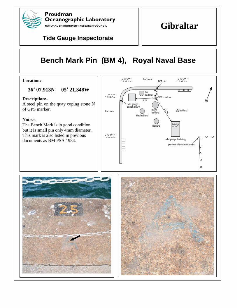
Bench Mark Pin (BM 4), Royal Naval Base
Location:-
36˚ 07.913N 05˚ 21.348W
Description:- A steel pin on the quay coping stone N of GPS marker. Notes:- The Bench Mark is in good condition but it is small pin only 4mm diameter. This mark is also listed in previous documents as BM PSA 1984.

16
Tide Gauge Inspectorate
Gibraltar
GPS Marker, Royal Naval Base
Location:-
36˚ 07.911N 05˚ 21.348W Description:- An Iron bolt NW of tide gauge building. Notes:- The Bench mark is in good condition.

17
Tide Gauge Inspectorate
Gibraltar
German Altitude Marker, Royal Naval Base
Location:-
36˚ 07.903N 05˚ 21.330W Description:- A horizontal steel pin in the pillar at the NW corner, W face of RN HQ. Notes:- The Bench Mark shows signs of corrosion.

18
Tide Gauge Inspectorate
Gibraltar
Naval Stores (BM 1), Royal Naval Base
Location:-
36˚ 07.927N 05˚ 21.250W Description:- An Ordnance Survey bracket at the NE corner E face of stores building.
Notes:- The photograph below shows the tide gauge building in the distance.

19
Tide Gauge Inspectorate
Gibraltar
Jumper Bastion (BM 2)
Location:-
36˚ 07.849N 05˚ 21.199W
Description:- An Ordnance Survey cut mark on the SW face of Jumpers Bastion 30cm above ground. Notes:- The Bench Mark is in good condition.

20
Tide Gauge Inspectorate
Gibraltar
Ragged Staff Gates (BM 3)
Location:-
36˚ 08.892N 05˚ 21.901W
Description:- An Ordnance Survey cut mark 30cm above ground. It is 2m SE from the W corner of the city walls and is 60m S of Ragged Staff Gates.
Notes:- The Bench Mark is in good condition but difficult to see.

21
Tide Gauge Inspectorate
Gibraltar
Kings Bastion (BM 5)
Location:-
36˚ 08.384N 05˚ 21.340W
Description:- A domed pin at the W corner recessed into wall. Notes:- The stonework around the Bench Mark is damaged and may be lost. The leg of the staple nearest to the BM (shown on the right hand photograph) was also levelled.

22
Tide Gauge Inspectorate
Gibraltar
Chatham Counterguard (BM 6)
Location:-
36˚ 08.559N 05˚ 21.306W
Description:- An Ordnance Survey cut mark at the SW corner on the S face 25cm above ground Notes:- The Bench Mark is in good condition. Thes bench mark has not been used in previously levelling.

23
Tide Gauge Inspectorate
Gibraltar
Tide Gauge Bench Mark (TGBM CP) Port Authority
Location:-
36˚ 08.894N 05˚ 21.895W
Description:- Brass bolt on the quay coping 1m W of the tide gauge. Notes:- This is a new Bench Mark installed in 2004.

24
Appendix B

25